Embed Size (px)
Citation preview
International Journal of Computer Networks & Communications (IJCNC) Vol.2, No.5, September 2010
DOI : 10.5121/ijcnc.2010.2502 16
A Link Layer Solution to Location Identification of
Emergency VoIP Callers
Saeideh Ashtarifar and Ashraf Matrawy
Department of System and Computer Engineering, Carleton University, Ottawa, Canada
Email: {sashtari, amatrawy}@sce.carleton.ca
August 25, 2010
.
ABSTRACT
Identifying the geographical location of a host on the Internet is a very challenging task. Due to a number of
reasons, there is no direct mechanism that could enable this identification. Several approaches have been
proposed to solve this problem but these have not proved to be suitable for some applications specially the
critical VoIP calls. In this paper, we study this problem and propose the use of a MAC layer approach to
solve this problem. We propose a solution based on LLDP-MED (Link Layer Discovery Protocol for Media
Endpoint Devices) and compare it with LIS (Location Information Server). We discuss these two techniques
in terms of network delay for two groups of users (wired line and wireless Internet users) for emergency cases
and also discuss some other issues such as security and accuracy.
KEYWORDS
Emergency Call (EC), VoIP, PSAP, SIP, LLDP-MED, LIS, User Agent, Proxy Server
1. INTRDUCTION
One of the significant challenge that Internet telephony, using Voice-over-IP (VoIP), faces is
handling emergency calls. In traditional land-line telephones, the phone number is used as a key to
determine the physical location of the users. In IP telephony, the location of the users is not fixed
and the phone number (or any other keys) can not be simply used to locate the users. This is the
main reason that VoIP service providers do not support calling emergency numbers (like 911 in
North America or 112 in Europe ) in the same way they do support it in land-line telephones. One of
the main steps to handle an emergency call in VoIP networks, is finding the actual location of the
user (caller) [1]. Although there is active research on this issue, still no clear solution has been
proposed that could be used in all situations.
One of the proposed solutions to determine the actual location of the users, is using a MAC layer
protocol [2], named LLDP-MED (Link Layer Discover Protocol for Media Endpoint Device [3]).
Using this protocol, the switches in which this protocol is enabled, send periodic messages to the
connected end users. These messages which will be discarded after a certain time contain
information such as: the switch name, the number of the port to which the end device is connected.
There is a database on each administrative domain with the information, which maps switch/port
International Journal of Computer Networks & Communications (IJCNC) Vol.2, No.5, September 2010
17
number to a physical address. So each end device can ask the database about its physical location
based on the information sent by switch. We will have more discussion on this protocol in section 3.
In this paper, we have proposed a solution to determine the physical location of VoIP users
utilizing LLDP-MED protocol. In the existing methods by LLDP, the end users get their
information from a database based on the received information from the switch. Then they use this
location information as their actual physical location for location-based applications like making
emergency calls. In our approach, the switch inserts location information to the MAC layer of every
packet passing through the switch. In this way, when an end user makes an emergency call, this
request will have to go to the first level switch which we assume have to be LLDP-enabled. The
switch (or the Access Point for the wireless users), based on the port number of the receiving packet,
puts location information in MAC header of that packet and forwards it to the next hop. This field is
not overwritten by the next hops. At the destination, the related service that is supposed to make
decision about this packet based on the location of the sender can have access to that information by
reading the MAC layer information.
One of the clear advantage of this method is that the user can not put fake location information
as opposed to other cases where the user (i.e. its client) is supplying the location information. This
solution has a very significant benefit for the nomadic user because once a user disconnects from
one port and connects to another port (at a diff erent location) and starts to send packets, its packets
will be stamped with the location information of newly connected port. Therefore with an updated
database for the switch, we can be sure that every packet will have the correct information stamped
to its MAC header. This should increase the chances of reaching at the destination with up-to-date
location information. We will talk about this and the other advantages of our proposed solution in
section 5. We have implemented our solution in the network simulator NS2 (The Network
Simulator 2 [4]) for VoIP application using SIP (Session Initiation Protocol [5]) protocol, which is
doing the signaling for setting up and terminating calls. This protocol is widely used by VoIP
service providers. We have defined a new agent at the switch, which stamps every packet from the
users destined to the VoIP proxy server, with location information in the MAC headers (Section
3.3). For comparison, we have considered an application layer technique, using Location
Information Server (LIS), (Section 4) and implemented this method in NS2 as well (Section 4.2). In
Section 5 we discuss some advantages of our proposed model. Section 6 presents our delay analysis
and compares LLDP-MED and LIS in a wired environment and in Section 7 we compare these two
techniques in terms of delay and network congestion for the wireless users. Section 8 concludes the
paper.
2. Related Works
Since determining the geographical location of caller plays a major roll to handle emergency cases,
this issue has been the target of a lots of researches. Also a user’s location must be determined both
indoor and outdoor. There are several techniques for addressing this problem. Most of the
techniques can be categorized into two main groups [6]:
International Journal of Computer Networks & Communications (IJCNC) Vol.2, No.5, September 2010
18
2.1. Database Approaches:
In these methods, all of the necessary information is kept in one or multiple databases. Compare to
the other methods, they are more accurate but need information entered and keep update manually.
Outdated information and false or faulty data may happen. Some instances of these methods are:
Geo Track , Geo Cluster [7], Who is lookup [8], DHCP lookup [9], CDP [10], LIS [11] ,
LLDP-MED [2] and user-supplied location information. Some of these methods like ”Geo Cluster”
and ”Geo Track”, need special hardware like probes. In those methods like DHCP lookup or LIS,
which are based on IP addresses, one may face two problems: first, the actual IP address of the user
is not always available; for example with the presence of NAT, proxy or VPN the actual IP address
will be obscured, or in the case of remote control, the IP address attached to the network is that of
the remote machine. Second, even if the actual IP address of the user be available, there is no
guarantee that real information of that IP address, such as geographical address, will be available
and correct.
� However, since the layer two mechanisms like CDP and LLDP-MED don’t use IP
addresses as the user identifier, they don’t have such problems. The related issue for these protocols
is that every node which is somehow involved with an emergency call, must support these protocols.
In this paper we will compare our proposed solution based on LLDP-MED, with one technique of
this group, LIS.
2.2.Measurement Approaches:
These techniques are mainly based on the relationship between the network delay and physical
distances. However, in addition to distance, some other factors like link failure and network
congestion may aff ect this delay, hence these methods can not always provide a good estimate for
the caller’s location. In the most of these methods, some nodes at the known locations are
considered to be ”Landmarks” with the ability to respond to ping or sending ICMP messages, that
adds a condition to the network. In some of these such as Geo Ping [7], the density of probing
Landmarks is very low and sequentially it is faster and cheaper than the other methods, but may not
be accurate. Even CBG [12] that provides a better estimate than Geo Ping, is not accurate enough to
handle an emergency call. Compared to Geo Ping, more accurate methods do multiple
measurements, so they impose more overhead to the network and take much more time to
determine the location of the user. Some other methods like TBG [13], which consider a
combination of topology and delay, provide a better estimate. However, the issue for these methods
is that at first the topology of the network should be generated and the location of some nodes like
passive Landmarks, which are used to provide the better accuracy, should be validated, so these
techniques could be costly in terms of delay when considered for a time-critical application.
Further more, these methods are usually time consuming which make them inappropriate for
handling real time applications like handling emergency calls, in which finding the actual location
of caller is vital. These can be used as validation tool to confirm the location of the user after any
change in his/her location and before establishing an emergency call. However, in these methods
there is a trade off between the time it takes to determine the actual location of emergency caller
and the accuracy.
International Journal of Computer Networks & Communications (IJCNC) Vol.2, No.5, September 2010
19
Out of these two groups, there are some other possibilities for those VoIP clients who are using
wireless connections, to determine their geographical locations, either by themselves or by their
proxy server. For instance, the user can be aware of its own location from a GPS (Global
Positioning System) receiver [14]. However, this solution is more appropriate for the outdoor users
but there are some limitations, which cause this solution not to be suitable for all cases, like when
the wireless users are inside the building or the other places where GPS signals are not available.
Another solution is using a bluetooth beacon to determine the user’s location [15]. The other
possible solution for the wireless users, is triangulation calculation. A wireless user location can be
pinpointed by multiple access points and stored in a location server. Then the user can ask about its
location from the location server by using SIP event notification [16].
3. A MAC Layer Solution using LLDP-MED
In this section, we introduce our solution based on a MAC layer protocol, named LLDP-MED.
3.1. The LLDP-MED Protocol
As we described in section 2, there are several methods to determine the physical location of a host
on the Internet. One of these techniques introduced in [10] is using Cisco Discovery Protocol (CDP).
Using this protocol, all of the switches send messages periodically to the end users, which contain
the switch name and the port number. Then every user can send a query to the database, located in
the administrative domain, and ask about its physical location. The database contains a mapping
between the switch/port number and the location that is refreshed on a periodic basis. Because
every port of a switch leads to a outlet in a specific room, the accuracy of this method is room level
which is suitable for the emergency cases.
Since CDP is Cisco-specific, a general solution called Link Layer Discovery Protocol for Media
Endpoint Devices(LLDP-MED) is introduced. In fact, Link Layer Discovery Protocol (LLDP) or
IEEE 802.1AB is a multi vendor standard which can be used for IP telephony in Enterprise
networks.
LLDP-MED (ANSI/TIA-1057/D6) extends the LLDP for the location discovery of end devices
[3]. This standard allows some devices like switches to advertise information in LLDPDU frames to
the endpoints. The information distributed via LLDP can be stored by the recipients in a standard
management information base (MIB), which can be accessed by a network management system
(NMS) [3]. This protocol supports some advanced features for VoIP endpoint devices, such as,
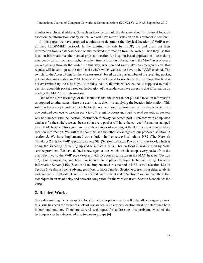
making emergency calls. Figure 1, illustrates how LLDP-MED works, as it was described before,
there is a database in each administrative domain with mapping information between switch/port
number and physical location (LLDP-MED database in figure 1). Once a user tries to make an
emergency call, their request goes through the switch. This request is stamped, with the location
information, by the switch, and based on the LLDP-MED database. The request then is forwarded
to the proxy server.
International Journal of Computer Networks & Communications (IJCNC) Vol.2, No.5, September 2010
20
Figure 1: Basic LLDP-MED Architecture
This standard is not specific to any VoIP architecture or system management architecture.
Switches, which support this protocol, can advertise the location information to the end users, but
they also have the ability to insert this information to the MAC header of the passing packets.
In our implementation we have considered this ability of the switch, which is stamping packets
by location information. The switch can do this for all of the packets, which are passing through it,
or check the LLDP-MED TLV(Type-Length-Value) types and just perform this for the VoIP
packets. In the following section, different fields of LLDP-MED are explained.
3.2. LLDP-MED Header Fields
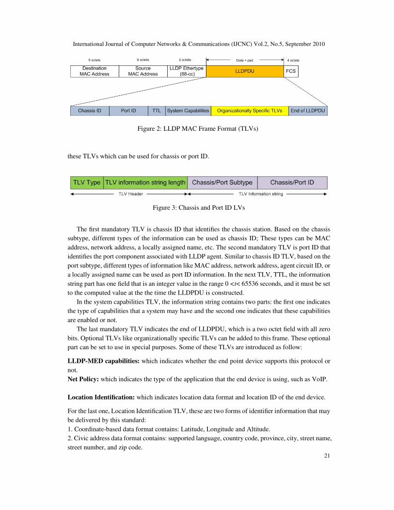
In this part, we explain the header format of LLDP-MED frame, as shown in Figure 2.
Some of these TLVs are mandatory, including: Chassis ID, Port ID, TTL, System Capabilities
and End of LLDPDU. Each LLDPDU must contain one, and only one of each mandatory TLVs.
These fields value remain constant while the connection remains operational. Each mandatory TLV
has two main parts: header and information. The first part contains TLV type and the length of the
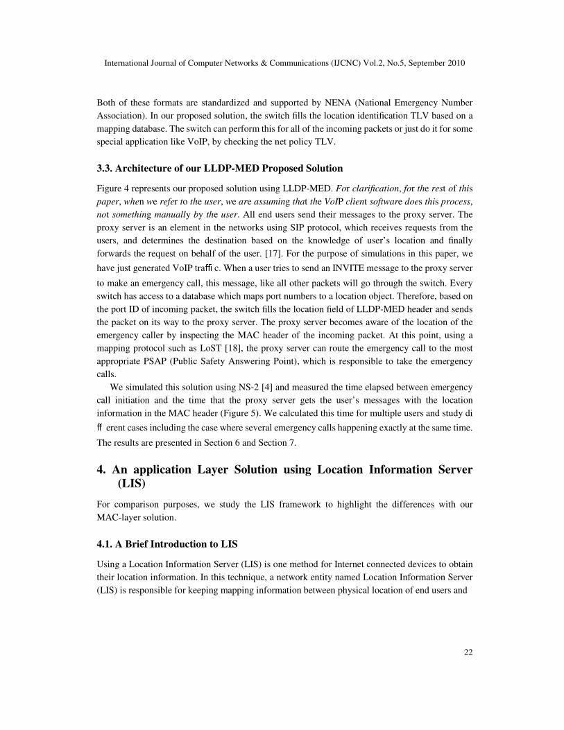
information and the second part contains the actual information. Figure 3 illustrates one of
International Journal of Computer Networks & Communications (IJCNC) Vol.2, No.5, September 2010
21
Figure 2: LLDP MAC Frame Format (TLVs)
these TLVs which can be used for chassis or port ID.
Figure 3: Chassis and Port ID LVs
The first mandatory TLV is chassis ID that identifies the chassis station. Based on the chassis
subtype, different types of the information can be used as chassis ID; These types can be MAC
address, network address, a locally assigned name, etc. The second mandatory TLV is port ID that
identifies the port component associated with LLDP agent. Similar to chassis ID TLV, based on the
port subtype, different types of information like MAC address, network address, agent circuit ID, or
a locally assigned name can be used as port ID information. In the next TLV, TTL, the information
string part has one field that is an integer value in the range 0 <t< 65536 seconds, and it must be set
to the computed value at the the time the LLDPDU is constructed.
In the system capabilities TLV, the information string contains two parts: the first one indicates
the type of capabilities that a system may have and the second one indicates that these capabilities
are enabled or not.
The last mandatory TLV indicates the end of LLDPDU, which is a two octet field with all zero
bits. Optional TLVs like organizationally specific TLVs can be added to this frame. These optional
part can be set to use in special purposes. Some of these TLVs are introduced as follow:
LLDP-MED capabilities: which indicates whether the end point device supports this protocol or
not.
Net Policy: which indicates the type of the application that the end device is using, such as VoIP.
Location Identification: which indicates location data format and location ID of the end device.
For the last one, Location Identification TLV, these are two forms of identifier information that may
be delivered by this standard:
1. Coordinate-based data format contains: Latitude, Longitude and Altitude.
2. Civic address data format contains: supported language, country code, province, city, street name,
street number, and zip code.
International Journal of Computer Networks & Communications (IJCNC) Vol.2, No.5, September 2010
22
Both of these formats are standardized and supported by NENA (National Emergency Number
Association). In our proposed solution, the switch fills the location identification TLV based on a
mapping database. The switch can perform this for all of the incoming packets or just do it for some
special application like VoIP, by checking the net policy TLV.
3.3. Architecture of our LLDP-MED Proposed Solution
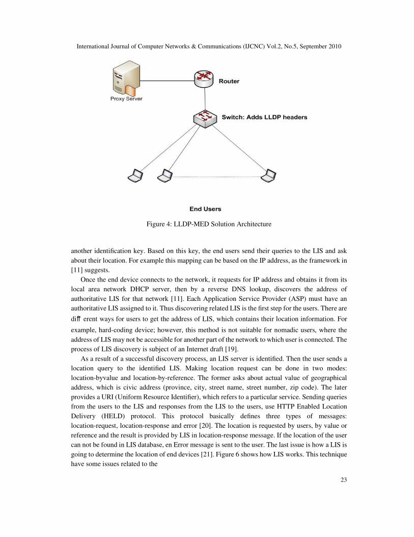
Figure 4 represents our proposed solution using LLDP-MED. For clarification, for the rest of this
paper, when we refer to the user, we are assuming that the VoIP client software does this process,
not something manually by the user. All end users send their messages to the proxy server. The
proxy server is an element in the networks using SIP protocol, which receives requests from the
users, and determines the destination based on the knowledge of user’s location and finally
forwards the request on behalf of the user. [17]. For the purpose of simulations in this paper, we
have just generated VoIP traffi c. When a user tries to send an INVITE message to the proxy server
to make an emergency call, this message, like all other packets will go through the switch. Every
switch has access to a database which maps port numbers to a location object. Therefore, based on
the port ID of incoming packet, the switch fills the location field of LLDP-MED header and sends
the packet on its way to the proxy server. The proxy server becomes aware of the location of the
emergency caller by inspecting the MAC header of the incoming packet. At this point, using a
mapping protocol such as LoST [18], the proxy server can route the emergency call to the most
appropriate PSAP (Public Safety Answering Point), which is responsible to take the emergency
calls.
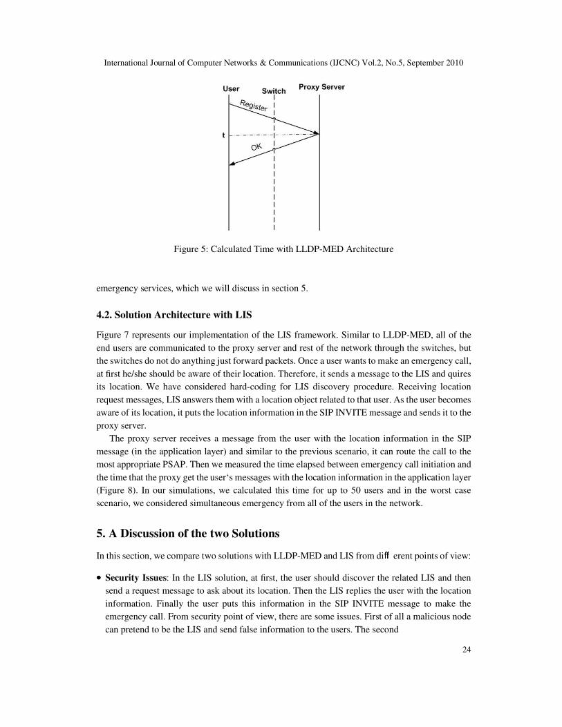
We simulated this solution using NS-2 [4] and measured the time elapsed between emergency
call initiation and the time that the proxy server gets the user’s messages with the location
information in the MAC header (Figure 5). We calculated this time for multiple users and study diff erent cases including the case where several emergency calls happening exactly at the same time.
The results are presented in Section 6 and Section 7.
4. An application Layer Solution using Location Information Server
(LIS)
For comparison purposes, we study the LIS framework to highlight the differences with our
MAC-layer solution.
4.1. A Brief Introduction to LIS
Using a Location Information Server (LIS) is one method for Internet connected devices to obtain
their location information. In this technique, a network entity named Location Information Server
(LIS) is responsible for keeping mapping information between physical location of end users and
International Journal of Computer Networks & Communications (IJCNC) Vol.2, No.5, September 2010
23
Figure 4: LLDP-MED Solution Architecture
another identification key. Based on this key, the end users send their queries to the LIS and ask
about their location. For example this mapping can be based on the IP address, as the framework in
[11] suggests.
Once the end device connects to the network, it requests for IP address and obtains it from its
local area network DHCP server, then by a reverse DNS lookup, discovers the address of
authoritative LIS for that network [11]. Each Application Service Provider (ASP) must have an
authoritative LIS assigned to it. Thus discovering related LIS is the first step for the users. There are
diff erent ways for users to get the address of LIS, which contains their location information. For
example, hard-coding device; however, this method is not suitable for nomadic users, where the
address of LIS may not be accessible for another part of the network to which user is connected. The
process of LIS discovery is subject of an Internet draft [19].
As a result of a successful discovery process, an LIS server is identified. Then the user sends a
location query to the identified LIS. Making location request can be done in two modes:
location-byvalue and location-by-reference. The former asks about actual value of geographical
address, which is civic address (province, city, street name, street number, zip code). The later
provides a URI (Uniform Resource Identifier), which refers to a particular service. Sending queries
from the users to the LIS and responses from the LIS to the users, use HTTP Enabled Location
Delivery (HELD) protocol. This protocol basically defines three types of messages:
location-request, location-response and error [20]. The location is requested by users, by value or
reference and the result is provided by LIS in location-response message. If the location of the user
can not be found in LIS database, en Error message is sent to the user. The last issue is how a LIS is
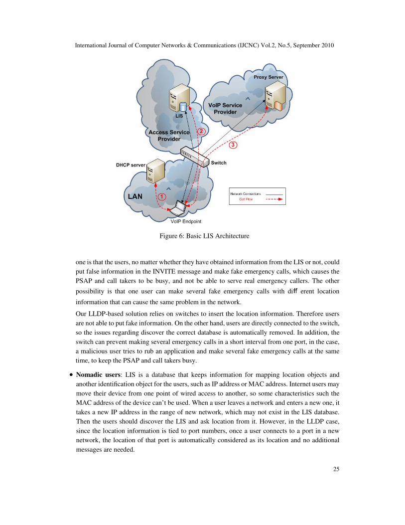
going to determine the location of end devices [21]. Figure 6 shows how LIS works. This technique
have some issues related to the
International Journal of Computer Networks & Communications (IJCNC) Vol.2, No.5, September 2010
24
Figure 5: Calculated Time with LLDP-MED Architecture
emergency services, which we will discuss in section 5.
4.2. Solution Architecture with LIS
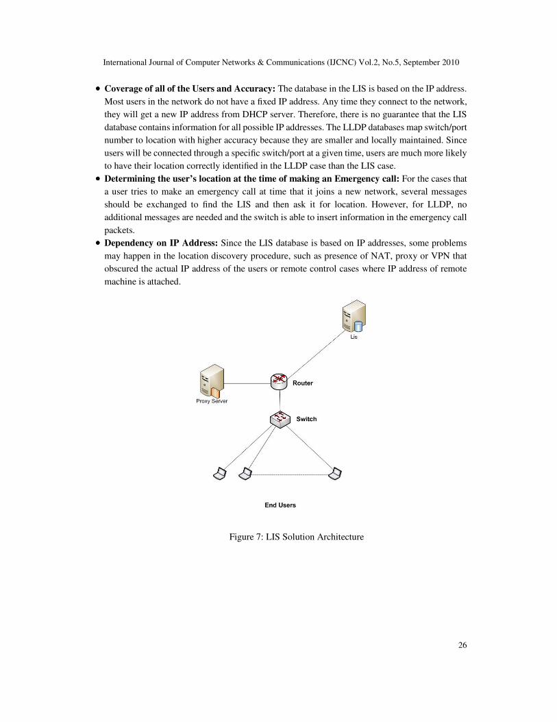
Figure 7 represents our implementation of the LIS framework. Similar to LLDP-MED, all of the
end users are communicated to the proxy server and rest of the network through the switches, but
the switches do not do anything just forward packets. Once a user wants to make an emergency call,
at first he/she should be aware of their location. Therefore, it sends a message to the LIS and quires
its location. We have considered hard-coding for LIS discovery procedure. Receiving location
request messages, LIS answers them with a location object related to that user. As the user becomes
aware of its location, it puts the location information in the SIP INVITE message and sends it to the
proxy server.
The proxy server receives a message from the user with the location information in the SIP
message (in the application layer) and similar to the previous scenario, it can route the call to the
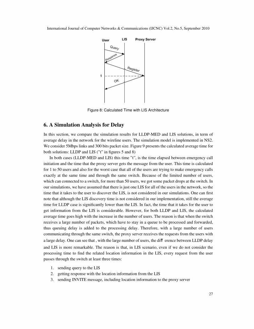
most appropriate PSAP. Then we measured the time elapsed between emergency call initiation and
the time that the proxy get the user‘s messages with the location information in the application layer
(Figure 8). In our simulations, we calculated this time for up to 50 users and in the worst case
scenario, we considered simultaneous emergency from all of the users in the network.
5. A Discussion of the two Solutions
In this section, we compare two solutions with LLDP-MED and LIS from diff erent points of view:
•••• Security Issues: In the LIS solution, at first, the user should discover the related LIS and then
send a request message to ask about its location. Then the LIS replies the user with the location
information. Finally the user puts this information in the SIP INVITE message to make the
emergency call. From security point of view, there are some issues. First of all a malicious node
can pretend to be the LIS and send false information to the users. The second
International Journal of Computer Networks & Communications (IJCNC) Vol.2, No.5, September 2010
25
Figure 6: Basic LIS Architecture
one is that the users, no matter whether they have obtained information from the LIS or not, could
put false information in the INVITE message and make fake emergency calls, which causes the
PSAP and call takers to be busy, and not be able to serve real emergency callers. The other
possibility is that one user can make several fake emergency calls with diff erent location
information that can cause the same problem in the network.
Our LLDP-based solution relies on switches to insert the location information. Therefore users
are not able to put fake information. On the other hand, users are directly connected to the switch,
so the issues regarding discover the correct database is automatically removed. In addition, the
switch can prevent making several emergency calls in a short interval from one port, in the case,
a malicious user tries to rub an application and make several fake emergency calls at the same
time, to keep the PSAP and call takers busy.
•••• Nomadic users: LIS is a database that keeps information for mapping location objects and
another identification object for the users, such as IP address or MAC address. Internet users may
move their device from one point of wired access to another, so some characteristics such the
MAC address of the device can’t be used. When a user leaves a network and enters a new one, it
takes a new IP address in the range of new network, which may not exist in the LIS database.
Then the users should discover the LIS and ask location from it. However, in the LLDP case,
since the location information is tied to port numbers, once a user connects to a port in a new
network, the location of that port is automatically considered as its location and no additional
messages are needed.
International Journal of Computer Networks & Communications (IJCNC) Vol.2, No.5, September 2010
26
•••• Coverage of all of the Users and Accuracy: The database in the LIS is based on the IP address.
Most users in the network do not have a fixed IP address. Any time they connect to the network,
they will get a new IP address from DHCP server. Therefore, there is no guarantee that the LIS
database contains information for all possible IP addresses. The LLDP databases map switch/port
number to location with higher accuracy because they are smaller and locally maintained. Since
users will be connected through a specific switch/port at a given time, users are much more likely
to have their location correctly identified in the LLDP case than the LIS case.
•••• Determining the user’s location at the time of making an Emergency call: For the cases that
a user tries to make an emergency call at time that it joins a new network, several messages
should be exchanged to find the LIS and then ask it for location. However, for LLDP, no
additional messages are needed and the switch is able to insert information in the emergency call
packets.
•••• Dependency on IP Address: Since the LIS database is based on IP addresses, some problems
may happen in the location discovery procedure, such as presence of NAT, proxy or VPN that
obscured the actual IP address of the users or remote control cases where IP address of remote
machine is attached.
Figure 7: LIS Solution Architecture
International Journal of Computer Networks & Communications (IJCNC) Vol.2, No.5, September 2010
27
Figure 8: Calculated Time with LIS Architecture
6. A Simulation Analysis for Delay
In this section, we compare the simulation results for LLDP-MED and LIS solutions, in term of
average delay in the network for the wireline users. The simulation model is implemented in NS2.
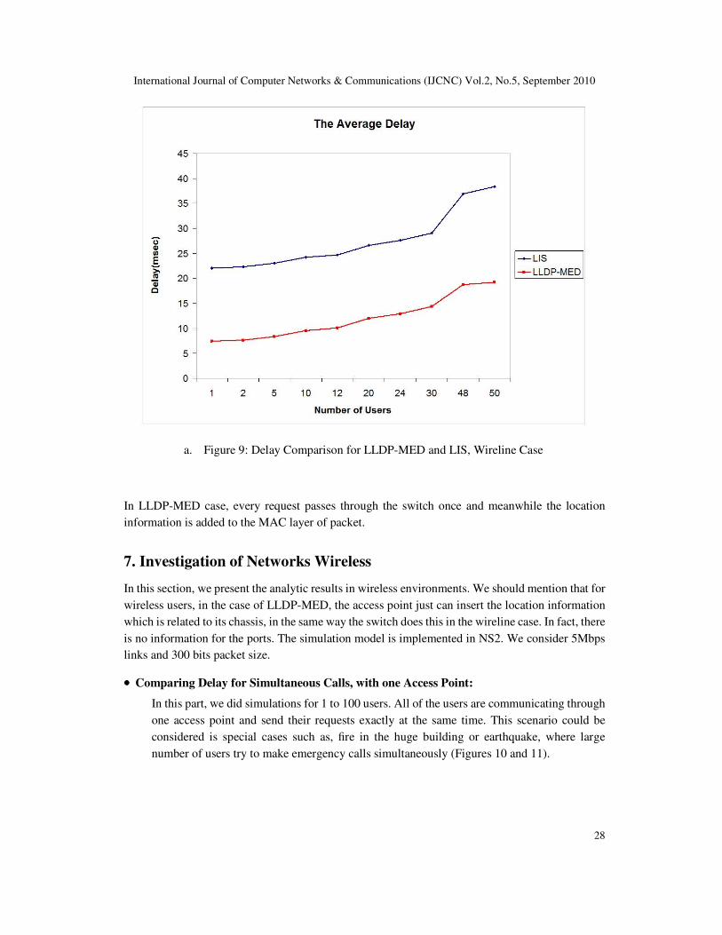
We consider 5Mbps links and 300 bits packet size. Figure 9 presents the calculated average time for
both solutions: LLDP and LIS (”t” in figures 5 and 8)
In both cases (LLDP-MED and LIS) this time ”t”, is the time elapsed between emergency call
initiation and the time that the proxy server gets the message from the user. This time is calculated
for 1 to 50 users and also for the worst case that all of the users are trying to make emergency calls
exactly at the same time and through the same switch. Because of the limited number of users,
which can connected to a switch, for more than 50 users, we got some packet drops at the switch. In
our simulations, we have assumed that there is just one LIS for all of the users in the network, so the
time that it takes to the user to discover the LIS, is not considered in our simulations. One can first
note that although the LIS discovery time is not considered in our implementation, still the average
time for LLDP case is significantly lower than the LIS. In fact, the time that it takes for the user to
get information from the LIS is considerable. However, for both LLDP and LIS, the calculated
average time goes high with the increase in the number of users. The reason is that when the switch
receives a large number of packets, which have to stay in a queue to be processed and forwarded,
thus queuing delay is added to the processing delay. Therefore, with a large number of users
communicating through the same switch, the proxy server receives the requests from the users with
a large delay. One can see that , with the large number of users, the diff erence between LLDP delay
and LIS is more remarkable. The reason is that, in LIS scenario, even if we do not consider the
processing time to find the related location information in the LIS, every request from the user
passes through the switch at least three times:
1. sending query to the LIS
2. getting response with the location information from the LIS
3. sending INVITE message, including location information to the proxy server
International Journal of Computer Networks & Communications (IJCNC) Vol.2, No.5, September 2010
28
a. Figure 9: Delay Comparison for LLDP-MED and LIS, Wireline Case
In LLDP-MED case, every request passes through the switch once and meanwhile the location
information is added to the MAC layer of packet.
7. Investigation of Networks Wireless
In this section, we present the analytic results in wireless environments. We should mention that for
wireless users, in the case of LLDP-MED, the access point just can insert the location information
which is related to its chassis, in the same way the switch does this in the wireline case. In fact, there
is no information for the ports. The simulation model is implemented in NS2. We consider 5Mbps
links and 300 bits packet size.
•••• Comparing Delay for Simultaneous Calls, with one Access Point:
In this part, we did simulations for 1 to 100 users. All of the users are communicating through
one access point and send their requests exactly at the same time. This scenario could be
considered is special cases such as, fire in the huge building or earthquake, where large
number of users try to make emergency calls simultaneously (Figures 10 and 11).
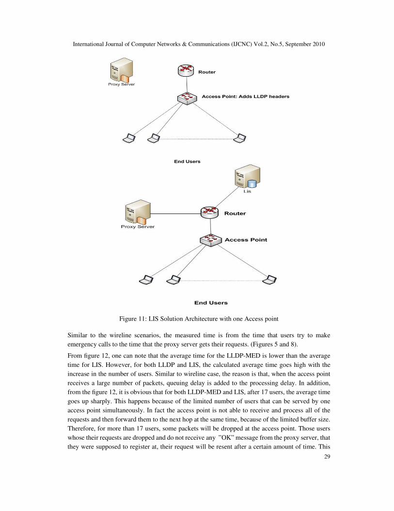
International Journal of Computer Networks & Communications (IJCNC) Vol.2, No.5, September 2010
29
Figure 11: LIS Solution Architecture with one Access point
Similar to the wireline scenarios, the measured time is from the time that users try to make
emergency calls to the time that the proxy server gets their requests. (Figures 5 and 8).
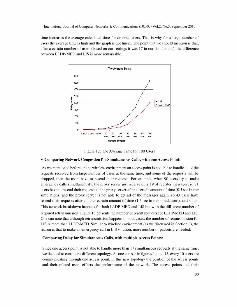
From figure 12, one can note that the average time for the LLDP-MED is lower than the average
time for LIS. However, for both LLDP and LIS, the calculated average time goes high with the
increase in the number of users. Similar to wireline case, the reason is that, when the access point
receives a large number of packets, queuing delay is added to the processing delay. In addition,
from the figure 12, it is obvious that for both LLDP-MED and LIS, after 17 users, the average time
goes up sharply. This happens because of the limited number of users that can be served by one
access point simultaneously. In fact the access point is not able to receive and process all of the
requests and then forward them to the next hop at the same time, because of the limited buffer size.
Therefore, for more than 17 users, some packets will be dropped at the access point. Those users
whose their requests are dropped and do not receive any ”OK” message from the proxy server, that
they were supposed to register at, their request will be resent after a certain amount of time. This
International Journal of Computer Networks & Communications (IJCNC) Vol.2, No.5, September 2010
30
time increases the average calculated time for dropped users. That is why for a large number of
users the average time is high and the graph is not linear. The point that we should mention is that,
after a certain number of users (based on our settings it was 17 in our simulations), the difference
between LLDP-MED and LIS is more remarkable.
Figure 12: The Average Time for 100 Users
•••• Comparing Network Congestion for Simultaneous Calls, with one Access Point:
As we mentioned before, in the wireless environment an access point is not able to handle all of the
requests received from large number of users at the same time, and some of the requests will be
dropped, then the users have to resend their requests. For example, when 90 users try to make
emergency calls simultaneously, the proxy server just receive only 19 of register messages, so 71
users have to resend their requests to the proxy server after a certain amount of time (0.5 sec in our
simulations) and the proxy server is not able to get all of the messages again, so 43 users have
resend their requests after another certain amount of time (1.5 sec in our simulations), and so on.
This network breakdown happens for both LLDP-MED and LIS but with the diff erent number of
required retransmission. Figure 13 presents the number of resent requests for LLDP-MED and LIS.
One can note that although retransmission happens in both cases, the number of retransmission for
LIS is more than LLDP-MED. Similar to wireline environment (as we discussed in Section 6), the
reason is that to make an emergency call in LIS solution, more number of packets are needed.
Comparing Delay for Simultaneous Calls, with multiple Access Points:
Since one access point is not able to handle more than 17 simultaneous requests at the same time,
we decided to consider a different topology. As one can see in figures 14 and 15, every 10 users are
communicating through one access point. In this new topology the position of the access points
and their related users effects the performance of the network. The access points and their
International Journal of Computer Networks & Communications (IJCNC) Vol.2, No.5, September 2010
31
connected users must be placed far enough from each other to avoid interference.
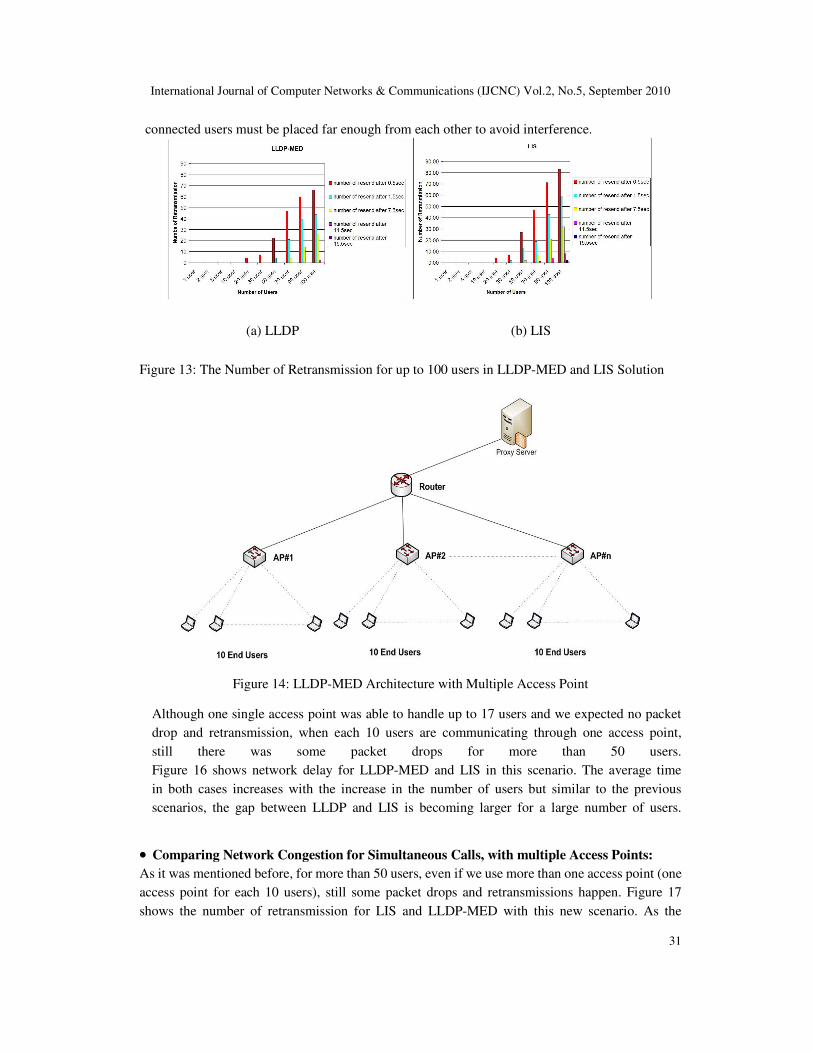
(a) LLDP (b) LIS
Figure 13: The Number of Retransmission for up to 100 users in LLDP-MED and LIS Solution
Figure 14: LLDP-MED Architecture with Multiple Access Point
Although one single access point was able to handle up to 17 users and we expected no packet
drop and retransmission, when each 10 users are communicating through one access point,
still there was some packet drops for more than 50 users.
Figure 16 shows network delay for LLDP-MED and LIS in this scenario. The average time
in both cases increases with the increase in the number of users but similar to the previous
scenarios, the gap between LLDP and LIS is becoming larger for a large number of users.
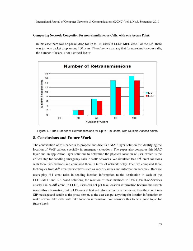
•••• Comparing Network Congestion for Simultaneous Calls, with multiple Access Points:
As it was mentioned before, for more than 50 users, even if we use more than one access point (one
access point for each 10 users), still some packet drops and retransmissions happen. Figure 17
shows the number of retransmission for LIS and LLDP-MED with this new scenario. As the

International Journal of Computer Networks & Communications (IJCNC) Vol.2, No.5, September 2010
32
number of users increase, the number of retransmission in LIS is more than LLDPMED.
Figure 16: The Average Time for 100 Users, with Multiple Access Points
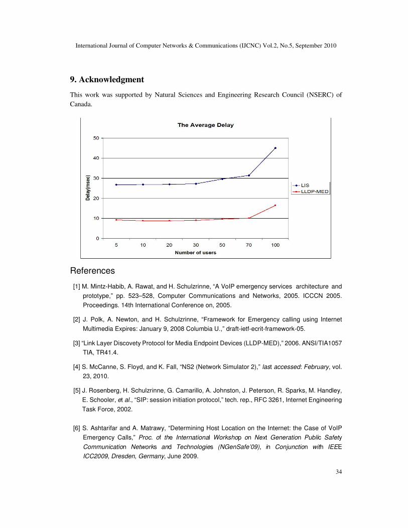
Comparing Delay for non-Simultaneous Calls, with one Access Point:
In this part, we consider a dierent behavior of the emergency callers: instead of simultaneous calls,
users make their emergency calls at a random time. We generated this random time with a uniform
distribution in the interval [0,1]. All of the users communicate through one access point. Figure 18
represents the average delay for LLDP-MED and LIS with the random start time. Similar to the
previous scenarios, the average time is increased with the number of users and the average time for
LLDP is significantly less than the average time for LIS. In addition, after 70 users the average time
is going up sharply for both cases, but for LIS, it is increasing significantly faster than LLDP-MED.
•
International Journal of Computer Networks & Communications (IJCNC) Vol.2, No.5, September 2010
33
Comparing Network Congestion for non-Simultaneous Calls, with one Access Point:
In this case there was no packet drop for up to 100 users in LLDP-MED case. For the LIS, there
was just one packet drop among 100 users. Therefore, we can say that for non-simultaneous calls,
the number of users is not a critical factor.
Figure 17: The Number of Retransmissions for Up to 100 Users, with Multiple Access points
8. Conclusions and Future Work
The contribution of this paper is to propose and discuss a MAC layer solution for identifying the
location of VoIP callers, specially in emergency situations. The paper also compares this MAC
layer and an application layer solutions to determine the physical location of user, which is the
critical step for handling emergency calls in VoIP networks. We simulated two diff erent solutions
with these two methods and compared them in terms of network delay. Then we compared these
techniques from diff erent perspectives such as security issues and information accuracy. Because
users play diff erent roles in sending location information to the destination in each of the
LLDP-MED and LIS based solutions, the reaction of these methods to DoS (Denial-of-Service)
attacks can be diff erent. In LLDP, users can not put fake location information because the switch
inserts this information, but in LIS users at first get information form the server, then they put it in a
SIP message and send it to the proxy server, so the user can put anything for location information or
make several fake calls with fake location information. We consider this to be a good topic for
future work.
International Journal of Computer Networks & Communications (IJCNC) Vol.2, No.5, September 2010
34
9. Acknowledgment
This work was supported by Natural Sciences and Engineering Research Council (NSERC) of
Canada.
References
[1] M. Mintz-Habib, A. Rawat, and H. Schulzrinne, “A VoIP emergency services architecture and
prototype,” pp. 523–528, Computer Communications and Networks, 2005. ICCCN 2005.
Proceedings. 14th International Conference on, 2005.
[2] J. Polk, A. Newton, and H. Schulzrinne, “Framework for Emergency calling using Internet
Multimedia Expires: January 9, 2008 Columbia U.,” draft-ietf-ecrit-framework-05.
[3] “Link Layer Discovety Protocol for Media Endpoint Devices (LLDP-MED),” 2006. ANSI/TIA1057
TIA, TR41.4.
[4] S. McCanne, S. Floyd, and K. Fall, “NS2 (Network Simulator 2),” last accessed: February, vol.
23, 2010.
[5] J. Rosenberg, H. Schulzrinne, G. Camarillo, A. Johnston, J. Peterson, R. Sparks, M. Handley,
E. Schooler, et al., “SIP: session initiation protocol,” tech. rep., RFC 3261, Internet Engineering
Task Force, 2002.
[6] S. Ashtarifar and A. Matrawy, “Determining Host Location on the Internet: the Case of VoIP
Emergency Calls,” Proc. of the International Workshop on Next Generation Public Safety
Communication Networks and Technologies (NGenSafe’09), in Conjunction with IEEE
ICC2009, Dresden, Germany, June 2009.
International Journal of Computer Networks & Communications (IJCNC) Vol.2, No.5, September 2010
35
[7] V. Padamanabban and L. Subramanian, “Determining the geographic location of Internet
hosts,” ACM SIGMETRICS Performance Evaluation Review, vol. 29, no. 1, pp. 324–325, 2001.
[8] J. Muir and P. Oorschot, “Internet geolocation: Evasion and counterevasion,” ACM Computing
Surveys (CSUR), vol. 42, no. 1, pp. 1–23, 2009.
[9] H. Schulzrinne, “Dynamic Host Configuration Protocol (DHCPv4 and DHCPv6) Option for Civic
Addresses Configuration Information,” draft-ietf-geopriv-dhcp-civil-09 (work in progress),
January, 2006.
[10] J. Kim, W. Song, and H. Schulzrinne, “An enhanced VoIP emergency services prototype,”
Information Systems for Crisis Response and Management (ISCRAM), 2006.
[11] M. Dawson, “The Internet location services model,” Computer Communications, vol. 31, no. 6,
pp. 1104–1113, 2008.
[12] B. Gueye, A. Ziviani, M. Crovella, and S. Fdida, “Constraint-based geolocation of internet
hosts,” IEEE/ACM Transactions on Networking (TON), vol. 14, no. 6, pp. 1219–1232, 2006.
[13] E. Katz-Bassett, J. John, A. Krishnamurthy, D. Wetherall, T. Anderson, and Y. Chawathe,
“Towards IP geolocation using delay and topology measurements,” in Proceedings of the 6th
ACM SIGCOMM conference on Internet measurement, pp. 71–84, ACM New York, NY, USA,
2006.
[14]R. Bajaj, S. Ranaweera, and D. Agrawal, “GPS: Location-tracking technology,”Computer, vol. 35, no. 4, pp. 92–94, 2002.
[15] A. LaMarca, Y. Chawathe, S. Consolvo, J. Hightower, I. Smith, J. Scott, T. Sohn, J. Howard,
J. Hughes, F. Potter, et al., “Place lab: Device positioning using radio beacons in the wild,”
Pervasive Computing, pp. 116–133, 2005.
[16] A. Roach et al., “SIP-specific event notification,” RFC 3265, June 2002.
[17] Z. Yuan, “SIP-based VoIP network and its interworking with the PSTN,” Electronics &
Communication Engineering Journal, vol. 14, pp. 273–282, 2002.
[18] H. Schulzrinne, H. Tschofenig, A. Newton, and T. Hardie, “LoST: A Protocol for Mapping
Geographic Locations to Public Safety Answering Points,” in Performance, Computing, and
Communications Conference, 2007. IPCCC 2007. IEEE Internationa, pp. 606–611, 2007.
[19] M. Thomson and J. Winterbottom, “Discovering the Local Location Information Server (LIS),”
draft-thomson-geopriv-lis-discovery-03 (work in progress), September, 2007.
[20] M. Barnes, J. Winterbottom, M. Thomson, and B. Stark, “HTTP Enabled Location Delivery
(HELD),” draft-ietf-geopriv-http-location-delivery-01 (work in progress), July, 2007.
[21] M. Dawson, J. Winterbottom, and M. Thomson, IP location. McGraw-Hill Osborne Media,
2007.