Embed Size (px)
Citation preview

A LIGHTWEIGHT IMAGED BASED BRIDGE INSPECTION SYSTEM USING FISHING POLE, FISHING LINE AND FISHEYE CAMERA
Yi Chu Chen, Shih Chung Kang*, and Chi En Yang
Department of Civil Engineering, Nation Taiwan University, Taipei, Taiwan
* Corresponding author ([email protected])
ABSTRACT: Visual inspection is currently the major approach to evaluate the structural condition of a bridge. Some
researchers have done good work on applying special inspection vehicles and robot arms to increase the efficiency and
reachability of inspection process. However, such heavy equipment is highly restricted in working space and is hard to
deploy. In this research, we designed and implemented a portable device to facilitate the inspection. The proposed system is
lightweight (approx. 350g), including fisheye lens, a camera and a transmitter for real-time transmission of inspection data.
We rig the system using a fishing pole. This cable-based design greatly reduces the weight of the inspection system,
allowing inspectors to carry and deploy the device easily. A software system, which can control the motion of device and
process the vision information gathered from the camera, was also developed for a laptop computer. The proposed system is
expected to replace and enhance current bridge inspection methods.
Keywords: Bridge Inspection, Portable Device, Real-time Vision, Fisheye Camera
1. INTRODUCTION
Bridge inspection is a critical task to ensure the safety and
serviceability of bridges. In the U.S., the frequency of
bridge inspection is set to 2 years interval in general [1],
older bridges may need to be monitored more frequently.
In Taiwan, inspection for steel bridges is crucial due to the
hot and humid climate [2]. In state of practice, most
inspections mainly rely on visual inspection [3]. Inspectors
are sent beneath the bridge either by means of an
inspection vehicle or temporarily erected scaffolding [4].
This not only is labor-intensive and time-consuming, but
also poses threat on inspectors’ safety [5]. Furthermore, the
accuracy of evaluation result varies according to the
knowledge, experience and diligence of inspectors [5].
Researches have been conducted on the solution of
applying robot arms and vision systems for replacing
human works [6-7], some with machine vision technique to
enhance robot arm performance [8]. However, these
approaches have a major drawback on flexibility. To reach
deeper beneath a bridge, the robot arm applied needs to be
heavy in order to support its own weight, and thus needs a
firm and solid support structure, e.g. a special designed
vehicle with outriggers. As a result, the whole inspection
system is heavy and tardy; operations can be done only on
relatively larger bridges, and the equipment cost will be
very high. In this research, we propose an inspection
system featuring the use of cables. Cables can carry much
more load then the weight of itself, thus can extent to a
considerable length without making the system weighty.
The maximum weight of a complete digital camera system
is less than 2 kilogram; a lightweight camera is only
around 350 gram. Therefore, we can highly reduce the
weight of an inspection system compared with former
approaches, making it easy to be carried and deployed. In
the research, we aimed at developing a robust methodology
for optimizing system performance. A prototype system
was assembled to test the feasibility of proposed methods.
Fishing lines was used because it is very lightweight and
tough.
S24-2
813
.
Fig. 1 Two types of bridge inspection methods
2. IDEAS
In this research, we developed two types of methods to
operate the lightweight cable based bridge inspection
system. These two methods are illustrated in Fig. 1.
Method 1: Resonance Frequency Swinging Method
The first method is called “resonance frequency swing
method”. A motor is set to create small reciprocating
motion on the top of the fishing line. Inspectors can adjust
the motor to make the motion cycle match to the frequency
of fishing line length. Once the cycles are matched, the
swing amplitude will gradually increase. Therefore, with
small power motor the system can create large swing
amplitude. The large amplitude can send digital camera to
the deeper location beneath the bridge. Because the fishing
line is longer than 3 meters, the system swinging cycle
would be long; in other words, the camera will not swing
too fast. Bridge inspectors can adjust the length of the
fishing line and motor speed to achieve suitable amplitude.
Method 2: Merry-Go-Round Spinning Method
The second method is called “merry-go-round spinning
method”. This method attaches the fishing line to a small
length rod arm. Inspectors can adjust the spinning speed to
obtain different amplitude of the camera. Higher speed
would lead to larger amplitude, and vice versa. By
adjusting fishing line length and spinning frequency,
inspectors can achieve suitable amplitude.
Discussion of Two Methods
First, the “resonance frequency swing method” can achieve
larger inspection area. The “merry-go-round spinning
method” needs considerably large horizontal space for
spinning thus the cable length is limited. Next, the “merry-
go-round spinning method” can provide better camera
stability, i.e. we can make camera always looks up without
attach another servo or motor. The “resonance frequency
swing method” needs to attach additional servos to adjust
the direction of the digital camera. It is still a better way to
use additional servo to adjust camera direction by remote
control in both methods. The camera moves faster in
merry-go-round spinning method, therefore the camera
needs shorter exposure time.
Both these two methods use fishing line as support
mechanism. The fishing line only has tension force so it
can carry heavy objects in an efficient way.
3. PROTOTYPE OF BRIDGE INSPECTION
PLATFORM
S24-2
814

The bridge inspection system needs a platform to collocate
all the necessary devices such as servo, digital camera,
wireless transmission module and batteries. The prototype
of bridge inspection platform we developed is shown in Fig.
2. The total weight of the platform is only around 350
grams.
Hardware:
The platform consists of one control board, one Bluetooth
module, one radio transmission module, one 180 degree
servo, one fisheye camera, one battery and two ultrasonic
distance sensors. The main hardware components are
Innovati company products. The servo can allow inspectors
to adjust camera direction and let the lens facing the bridge
bottom. Top ultrasonic distance sensor is used to measure
the distance between the platform and bridge bottom,
Bottom ultrasonic distance sensor can measure the clear
distance below the platform and ground. The distance
information can help inspectors to prevent collision
between the device and the bridge or other objects. The
servo and ultrasonic distance sensors are controlled by the
control board, which uses Bluetooth to communicate with
laptop computer. The platform uses radio transmission
module to send camera image back to laptop.
Software:
We use Microsoft Robotics Developer Studio (MSRDS) as
the software platform. The control program is developed
with Visual Programming Language (VPL) and is
illustrated in Fig. 3. In this research, we use C# as the
program language to develope a “Bridge Inspection System
Service” which can control the Innovati hardware
components in VPL through Bluetooth communication.
The control program can also acquire ultrasonic distance
sensors’ reading.
4. FIELD EXPERIMENT
We have finished the first step of field experiment. The
setup of bridge inspection system is shown in Fig. 4.
Besides the bridge inspection hardware platform, there are
also a laptop computer, a radio transmission module (for
camera image transmission) and a 12V battery. The laptop
computer can display the camera image instantly and
communicate with the hardware platform by the input of a
gamepad. Bridge inspectors can easily adjust the camera
direction base on real-time monitoring the swinging motion.
Fig. 2 Prototype of bridge inspection platform
Fig. 3 The control program of bridge inspection system
S24-2
815
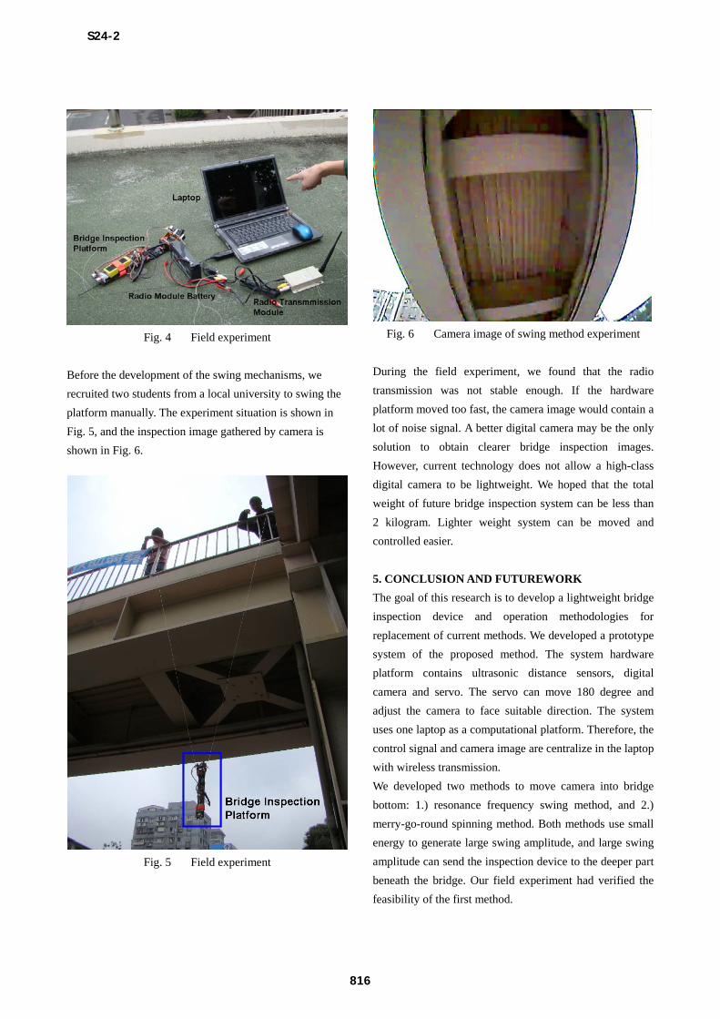
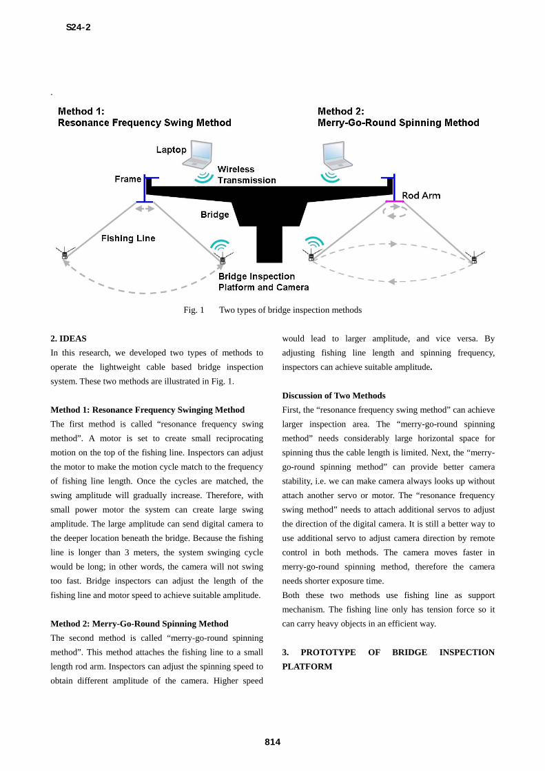
Fig. 4 Field experiment
Before the development of the swing mechanisms, we
recruited two students from a local university to swing the
platform manually. The experiment situation is shown in
Fig. 5, and the inspection image gathered by camera is
shown in Fig. 6.
Fig. 5 Field experiment
Fig. 6 Camera image of swing method experiment
During the field experiment, we found that the radio
transmission was not stable enough. If the hardware
platform moved too fast, the camera image would contain a
lot of noise signal. A better digital camera may be the only
solution to obtain clearer bridge inspection images.
However, current technology does not allow a high-class
digital camera to be lightweight. We hoped that the total
weight of future bridge inspection system can be less than
2 kilogram. Lighter weight system can be moved and
controlled easier.
5. CONCLUSION AND FUTUREWORK
The goal of this research is to develop a lightweight bridge
inspection device and operation methodologies for
replacement of current methods. We developed a prototype
system of the proposed method. The system hardware
platform contains ultrasonic distance sensors, digital
camera and servo. The servo can move 180 degree and
adjust the camera to face suitable direction. The system
uses one laptop as a computational platform. Therefore, the
control signal and camera image are centralize in the laptop
with wireless transmission.
We developed two methods to move camera into bridge
bottom: 1.) resonance frequency swing method, and 2.)
merry-go-round spinning method. Both methods use small
energy to generate large swing amplitude, and large swing
amplitude can send the inspection device to the deeper part
beneath the bridge. Our field experiment had verified the
feasibility of the first method.
S24-2
816

This research is still at the beginning stage. The quality of
bridge inspection image still needs improvement. We
generate the swing motion of the inspection platform
manually. In the near future, we will develop suitable
mechanism to swing the platform automatically. After we
improve the support frame of the platform, we will
implement the two proposed operation methods. The
improved bridge inspection device should be less than 2
kilogram and can be easily deployed and controlled by
only 2 inspectors. With the use of this lightweight cable
based bridge inspection system, we believe that bridge
inspection can be more efficient, low-cost and flexible in
the future.
REFERENCES
[1]“White paper on bridge inspection and rating”, Journal
of Bridge Engineering 14 (1), pp. 1-5, 2009.
[2] “Code for Inspection and Maintenance of Highway
Steel Structured Bridges”, Ministry of Transportation and
Communications (in Taiwan), 2008.
[3] “Bridge Inspections Training Manual”, Federal
Highway Administration (FHWA), 1991.
[4] Shibata Tsutomu, Shibata Atsushi, “Summary Report
of Research and Study on Robot Systems for Maintenance
of Highways and Bridges”, Robot, no. 118, JARA Tokyo,
Japan, pp. 41– 51, Sep. 1997.
[5] Oh, J.-K., Jang, G., Oh, S., Lee, J.H., Yi, B.-J., Moon,
Y.S., Lee and J.S., Choi, Y., “Bridge inspection robot
system with machine vision”, Automation in Construction
18 (7), pp. 929-941, 2009.
[6] J.-K. Oh, A.-Y. Lee, S.M. Oh, Y. Choi, B.-J. Yi, H.W.
Yang, “Design and control of bridge inspection robot
system”, IEEE Int. Conf. on Mechatronics and Automation,
pp. 3634–3639, 2007.
[7] DeVault, J.E., “Robotic system for underwater
inspection of bridge piers”, IEEE Instrumentation and
Measurement Magazine 3 (3), pp. 32-37, 2000.
[8] Tung, P.-C., Hwang, Y.-R. and Wu, M.-C., “The
development of a mobile manipulator imaging system for
bridge crack inspection”, Automation in Construction, 11
(6), pp. 717-729, 2002.
S24-2
817