Embed Size (px)
Citation preview
A Life-Cycle View of Architecture Analysis and Design Methods
Rick Kazman
Robert L. Nord
Mark Klein
September 2003
TECHNICAL NOTECMU/SEI-2003-TN-026
Pittsburgh, PA 15213-3890
A Life-Cycle View ofArchitecture Analysisand Design Methods CMU/SEI-2003-TN-026
Rick Kazman
Robert L. Nord
Mark Klein
Unlimited distribution subject to the copyright.
September 2003
Architecture Tradeoff Analysis Initiative

This work is sponsored by the U.S. Department of Defense.
The Software Engineering Institute is a federally funded research and development center sponsored by the U.S. Department of Defense.
Copyright 2003 by Carnegie Mellon University.
Requests for permission to reproduce this document or to prepare derivative works of this documentshould be addressed to the SEI Licensing Agent.
NO WARRANTY
THIS CARNEGIE MELLON UNIVERSITY AND SOFTWARE ENGINEERING INSTITUTE MATERIAL IS FURNISHED ON AN “AS-IS” BASIS. CARNEGIE MELLON UNIVERSITY MAKES NO WARRANTIES OF ANY KIND, EITHER EXPRESSED OR IMPLIED, AS TO ANY MATTER INCLUDING, BUT NOT LIMITED TO, WARRANTY OF FITNESS FOR PURPOSE OR MERCHANTABILITY, EXCLUSIVITY, OR RESULTS OBTAINED FROM USE OF THE MATERIAL. CARNEGIE MELLON UNIVERSITY DOES NOT MAKE ANY WARRANTY OF ANY KIND WITH RESPECT TO FREEDOM FROM PATENT, TRADEMARK, OR COPYRIGHT INFRINGEMENT.
This work was created in the performance of Federal Government Contract Number F19628-00-C-0003 with Carnegie Mellon University for the operation of the Software Engineering Institute, a federally funded research and development center. The Government of the United States has a royalty-free government-purpose license to use, duplicate, or disclose the work, in whole or in part and in any manner, and to have or permit others to do so, for government purposes pursuant to the copyright license under the clause at 252.227-7013.
Use of any trademarks in this report is not intended in any way to infringe on the rights of the trademark holder.
For information about purchasing paper copies of SEI reports, please visit the publications portion of our Web site (http://www.sei.cmu.edu/publications/pubweb.html).
Table of Contents
CMU/SEI-2003-TN-026 i
Abstract . . . . . . . . . . . . . . . . . . . . . . . . . . . . . . . . . . . . . . . . . . . . . . . . . . . . . . . . . vii
1 Introduction . . . . . . . . . . . . . . . . . . . . . . . . . . . . . . . . . . . . . . . . . . . . . . . . . . . 1
2 Description of the Methods . . . . . . . . . . . . . . . . . . . . . . . . . . . . . . . . . . . . . . . 52.1 Quality Attribute Workshop (QAW) . . . . . . . . . . . . . . . . . . . . . . . . . . . . . 5
2.2 Attribute-Driven Design (ADD) . . . . . . . . . . . . . . . . . . . . . . . . . . . . . . . . . 7
2.3 Architecture Tradeoff Analysis Method (ATAM) . . . . . . . . . . . . . . . . . . . 8
2.4 Active Reviews for Intermediate Designs (ARID) . . . . . . . . . . . . . . . . . . 9
2.5 Cost-Benefit Analysis Method (CBAM) . . . . . . . . . . . . . . . . . . . . . . . . . 10
3 Putting the Methods into Context . . . . . . . . . . . . . . . . . . . . . . . . . . . . . . . . . 13
4 Integrating the Methods with an Organization’s Life Cycle . . . . . . . . . . . . 154.1 Business Needs and Constraints . . . . . . . . . . . . . . . . . . . . . . . . . . . . . . 15
4.2 Requirements . . . . . . . . . . . . . . . . . . . . . . . . . . . . . . . . . . . . . . . . . . . . 16
4.3 Architecture Design . . . . . . . . . . . . . . . . . . . . . . . . . . . . . . . . . . . . . . . . 18
4.4 Detailed Design . . . . . . . . . . . . . . . . . . . . . . . . . . . . . . . . . . . . . . . . . . . 19
4.5 Maintenance . . . . . . . . . . . . . . . . . . . . . . . . . . . . . . . . . . . . . . . . . . . . . 19
5 Summary . . . . . . . . . . . . . . . . . . . . . . . . . . . . . . . . . . . . . . . . . . . . . . . . . . . . . 21
References. . . . . . . . . . . . . . . . . . . . . . . . . . . . . . . . . . . . . . . . . . . . . . . . . . . . . . . 23

ii CMU/SEI-2003-TN-026

List of Figures
CMU/SEI-2003-TN-026 iii
Figure 1: A Portion of a Utility Tree. . . . . . . . . . . . . . . . . . . . . . . . . . . . . . . . . . . . 17

iv CMU/SEI-2003-TN-026

List of Tables
CMU/SEI-2003-TN-026 v
Table 1: Methods and Life-Cycle Stages. . . . . . . . . . . . . . . . . . . . . . . . . . . . . . 13
Table 2: Life-Cycle Stages and Architecture-Based Activities. . . . . . . . . . . . . . 21

vi CMU/SEI-2003-TN-026
CMU/SEI-2003-TN-026 vii
Abstract
Many architecture-centric analysis and design methods have been created in the past 10 years at the Software Engineering Institute, beginning with the Software Architecture Analysis Method (SAAM). The SAAM inspired the creation of other methods, namely the Architecture Tradeoff Analysis MethodSM, the Quality Attribute Workshop, the Cost-Benefit Analysis Method, Active Reviews for Intermediate Designs, and the Attribute-Driven Design method.
As these methods become more widespread, more widely adopted, and integrated into the software development life cycle, organizations inevitably will want to tailor them. Conse-quently, organizations that wish to include quality-attribute-based requirements, explicit archi-tecture design, and architecture analysis in their software development life cycles will be best served if they can do so “organically.” The steps and artifacts of the five methods listed above, therefore, may require tailoring, blending, and, in some cases, removal when integrated into an existing life cycle.
This report examines these methods and activities to understand their commonalities and rela-tionships to life-cycle changes, and proposes a means of tailoring the activities so that they can fit more easily into existing life-cycle models.

viii CMU/SEI-2003-TN-026

CMU/SEI-2003-TN-026 1
1 Introduction
Many architecture-centric analysis and design methods have been created in the past 10 years, beginning with the Software Architecture Analysis Method (SAAM) [Kazman 96], which inspired the creation of other methods. The first such method that we created at the Software Engineering Institute (SEISM) was the Architecture Tradeoff Analysis MethodSM (ATAMSM)1 [Kazman 99]. As we gained experience from the ATAM, we expanded our reper-toire into more phases of the life cycle with the following methods:
• Quality Attribute Workshop (QAW) [Barbacci 03]
• Cost-Benefit Analysis Method (CBAM) [Kazman 01]
• Active Reviews for Intermediate Designs (ARID) [Clements 00]
• Attribute-Driven Design (ADD) method [Bass 03]
In this report, we examine these methods and their relationship to the software development life cycle (SDLC).
These methods share not only a common heritage, but also a common set of characteristics, aside from being architecture-centric. First, they all are scenario driven, with the scenarios serving as the “engine” for directing and focusing the methods’ activities. Second, they all are directed by operationalized quality attribute models. The SAAM focused on modifiability. The ATAM looks at tradeoffs among multiple quality attributes, while the ADD method shapes design decisions around quality attribute considerations. The QAW attempts to elicit and doc-ument quality attribute requirements accurately, particularly in the absence of explicit archi-tectural documentation. Third, the methods all focus on documenting the rationale behind the decisions made; in this way, the rationale serves as a knowledge base on which to base both existing and future decisions. Last, they all involve stakeholders so that multiple views of quality are elicited, prioritized, and embodied in the architecture.
Each of these methods includes a number of activities that logically belong to different parts of the traditional SDLC. Because these methods are designed for stand-alone use, however, the activities are embedded within them. The methods are typically run by a consultant, a quality-assurance group, or a researcher outside the developing organization’s immediate scope. Many organizations realize the value of having an outsider investigate their internal documents, even when the outsider’s activities mirror many of the activities that already take place within the organization. The outsider brings to the table a fresh perspective, objectivity, and a well-honed
1. SEI, Architecture Tradeoff Analysis Method, and ATAM are service marks of Carnegie Mellon University.
2 CMU/SEI-2003-TN-026
set of analytical skills, and is (hopefully) untainted by existing “group-think” or by political pressure. Although stand-alone methods have merit, they normally are not integrated with each other or into an organization’s SDLC.
A typical SDLC, as practiced in relatively mature software development organizations, includes (at least) the following activities:
• understanding of business needs and constraints
• elicitation and collection of requirements
• architecture design
• detailed design2
• implementation
• testing
• deployment
• maintenance
Of course, this list is not exhaustive, and many of these activities can be broken down into sub-activities (e.g., most include documentation and analysis sub-activities). Also, this list does not imply a particular development process—spiral, waterfall, agile, or any other. These items simply are distinct activities, with their own inputs, outputs, specialists, sub-activities, analysis techniques, and notations that must be undertaken in the development of any substantial soft-ware-intensive project. For example, architecture design as an activity includes inputs from requirements and business needs and constraints, produces outputs in the form of architecture documentation, and includes architecture analysis activities.
As architecture-centric methods become more widespread, more widely adopted, and inte-grated into an SDLC, organizations inevitably will want to tailor them. Consequently, organi-zations that wish to include the eliciting and gathering of quality-attribute-based requirements, explicit architecture design, and architecture analysis in their life cycles will be best served if they can do so “organically.” The steps and artifacts of the five architecture-centric methods listed above—QAW, ADD, ATAM, CBAM, and ARID—therefore may need to be tailored, blended, and, in some cases, removed entirely when the activities of these methods are inte-grated into an organization’s existing life cycle.
In this report, we survey the methods’ activities to understand their commonalities and to pro-pose a means of tailoring the activities so that they can fit more easily into existing SDLC models. In Section 2, we briefly describe the five architecture-centric methods without com-ment, and in Section 3, we discuss their relationship to software development activities. Their integration into an SDLC is covered in Section 4, which also involves deconstructing the
2. We use the term detailed design here because it is a widely accepted term. We are not implying that architecture designincludes no details. The architect definitely must go into detail in some areas (e.g., to specify the properties of componentsand their interactions), while detailed design typically involves algorithms, data structures, and realization.

CMU/SEI-2003-TN-026 3
methods into a collection of common architecture-based activities. We conclude in Section 5 by summarizing the relationship between life-cycle stages and architecture-based activities. Identifying these activities is a first step towards helping organizations tailor and embed the methods in their own SDLC, develop an SDLC based on these methods, or make connections to other software development processes.

4 CMU/SEI-2003-TN-026
CMU/SEI-2003-TN-026 5
2 Description of the Methods
In this section, we briefly describe the inputs to, outputs from, and the steps of each of the five methods. For each method, we present only the steps that actually involve analysis; we do not address tasks that concern working with the organization. So, for example, a step called “Present the Method” or a step called “Present Results” is not included here.
This report does not provide complete descriptions of any of these methods. For that, see the references noted in our discussion of each method. Our sole purpose in this report is to sketch each method’s inputs, activities, and outputs so that we can sufficiently understand how well they will integrate into an existing SDLC.
2.1 Quality Attribute Workshop (QAW)The QAW elicits, collects, and organizes software quality attribute requirements [Barbacci 03]. The vehicle for moving the QAW forward is the scenario. Specifically, the QAW elicits and records six-part scenarios, where the parts include the stimulus of the scenario, the source of the stimulus, the response, the response measure, the artifact stimulated, and the environ-ment.
2.1.1 Inputs to the QAW
Inputs include the
• system’s business/mission drivers
• system’s architectural plan
2.1.2 Steps of the QAW
This method includes the following steps:
1. Business/Mission Presentation: A representative of the stakeholder community presents the business/mission drivers for the system: its business drivers, key quality attributes, and high-level requirements.

6 CMU/SEI-2003-TN-026
2. Architectural Plan Presentation: Even though a detailed architecture may not exist, high-level system descriptions, context drawings, or command, control, communications, com-puter, intelligence, surveillance, and reconnaissance (C4ISR) documentation may. At this point in the workshop, a technical stakeholder presents the architectural plans as they stand with respect to these early documents.
3. Identification of Architectural Drivers: When the business drivers and architectural plan are presented, the QAW facilitators capture what they hear as architectural drivers. These include high-level requirements, business concerns and objectives, and quality attributes. At the conclusion of the presentation, the SEI facilitators share their list and ask for clarifi-cations and corrections.
4. Scenario Brainstorming: The facilitators review the parts of a scenario (stimulus, environ-
ment, and response)3 and ensure that each scenario is well formed during the workshop. Stakeholders in the workshop express scenarios representing their concerns about the sys-tem. Scenarios are offered by each stakeholder in a round-robin fashion. During a nominal QAW, two round-robin passes are made so that each stakeholder can contribute at least two scenarios. The facilitators ensure that representative scenarios exist for each architec-tural driver.
5. Scenario Consolidation: After the scenario brainstorming, the group consolidates the sce-narios when possible and prioritizes the remaining ones. If two scenarios are similar, stakeholders might split their votes when prioritizing them, causing neither scenario to be refined.
6. Scenario Prioritization: Each stakeholder is allocated a number of votes equal to 30% of the total number of scenarios generated after consolidation. Voting occurs in round-robin fashion, in two passes. During each pass, stakeholders allocate half of their votes.
7. Scenario Refinement: After scenarios are prioritized, the top four or five are refined in more detail and turned into six-part scenarios. This refinement adds a list of organizations, business drivers, actors, quality attributes, and questions to the raw scenario. The ques-tions concentrate on quality attribute aspects of the future architecture and include those that an architectural reviewer might ask during a scenario walkthrough at a technical inter-change meeting.
3. At this point, the scenario contains three parts because it is not refined into six parts until Step 7.

CMU/SEI-2003-TN-026 7
2.1.3 Outputs of the QAW
Outputs include a list of
• raw scenarios
• consolidated scenarios
• prioritized scenarios
• refined scenarios
2.2 Attribute-Driven Design (ADD)The ADD method defines a software architecture by basing the design process on the quality attributes the software must fulfill [Bass 03]. ADD documents a software architecture in a number of views; most commonly, a module decomposition view, a concurrency view, and a deployment view. ADD depends on an understanding of the system’s constraints and its func-tional and quality requirements, represented as six-part scenarios.
2.2.1 Inputs to ADD
Inputs include a
• set of constraints
• list of functional requirements
• list of quality attribute requirements
2.2.2 Steps of ADD
This method includes the following steps:
1. Choose the module to decompose: The module selected initially is usually the whole sys-tem. All required inputs for this module should be available (constraints and functional and quality requirements).
2. Refine the module according to the following steps:
a. Choose the architectural drivers from the set of concrete quality scenarios and func-tional requirements. This step determines what is important for this decomposition.
b. Choose an architectural pattern that satisfies the architectural drivers. Create (or select) the architectural pattern based on the tactics that can be used to achieve the architectural drivers. Identify children modules required to implement the tactics.
c. Instantiate modules and allocate functionality from the use cases using multiple views.
8 CMU/SEI-2003-TN-026
d. Define interfaces of the child modules: The decomposition provides modules and con-straints on the types of interactions among the modules. Document this information in the interface document for each module.
e. Verify and refine use cases and quality scenarios, and make them constraints for the child modules. This step verifies that nothing important was forgotten and prepares the children modules for further decomposition or implementation.
2.2.3 Output of ADD
The output includes a decomposition of the architecture, documented in at least three views: module decomposition, concurrency, and deployment.
2.3 Architecture Tradeoff Analysis Method (ATAM)The ATAM helps a system’s stakeholder community understand the consequences of architec-tural decisions on the system’s quality attribute requirements [Kazman 00]. These conse-quences are documented in a set of risks and tradeoffs that constitute the main output of the ATAM.
2.3.1 Inputs to the ATAM
Inputs include the
• system’s business/mission drivers
• existing architectural documentation
2.3.2 Steps of the ATAM
This method includes the following steps:
1. Present business drivers: A project spokesperson (ideally the project manager or system customer) describes which business goals are motivating the development effort and iden-tifies the primary architectural drivers (e.g., high availability, time to market, or high secu-rity).
2. Present architecture: The architect describes the architecture, focusing on how it addresses the business drivers.
3. Identify architectural approaches: The architect identifies, but does not analyze, architec-tural approaches.
CMU/SEI-2003-TN-026 9
4. Generate quality attribute utility tree: The quality factors that make up system “utility” (performance, availability, security, modifiability, etc.) are specified down to the level of scenarios, annotated with stimuli and responses, and prioritized.
5. Analyze architectural approaches: Based on the high-priority factors identified in the util-ity tree, the architectural approaches that address those factors are elicited and analyzed (e.g., an architectural approach aimed at meeting performance goals will be subjected to a performance analysis). Architectural risks, sensitivity points, and tradeoff points are iden-tified.
6. Brainstorm and prioritize scenarios: A larger set of scenarios is elicited from stakeholders and prioritized through a voting process.
7. Analyze architectural approaches: The highest ranked scenarios are treated as test cases—they are mapped to the architectural approaches previously identified. Additional approaches, risks, sensitivity points, and tradeoff points may be identified.
2.3.3 Outputs of the ATAM
Outputs include a
• list of architectural approaches
• list of scenarios
• set of attribute-specific questions
• utility tree
• list of risks
• list of non-risks
• list of risk themes
• list of sensitivity points
• list of tradeoffs
2.4 Active Reviews for Intermediate Designs (ARID)The ARID method blends Active Design Reviews with the ATAM, creating a technique for investigating designs that are partially complete [Clements 00]. Like the ATAM, the ARID method engages the stakeholders to create a set of scenarios that are used to “test” the design for usability—that is, to determine whether the design can be used by the software engineers who must work with it. The ARID method helps to find issues and problems that hinder the successful use of the design as currently conceived.
10 CMU/SEI-2003-TN-026
2.4.1 Inputs to ARID
Inputs include
• a list of seed scenarios
• the existing architectural/design documentation
2.4.2 Steps of ARID
This method includes the following steps:
1. Present the design: The lead designer presents an overview of the design and walks through the examples. During this time, participants follow the ground rule that no ques-tions concerning implementation or rationale are allowed, nor are suggestions about alter-nate designs. The goal is to see if the design is “usable” to the developer, not to find out why things were done a certain way or to learn about the secrets behind implementing the interfaces. This step results in a summarized list of potential issues that the designer should address before the design can be considered complete and ready for production.
2. Brainstorm and prioritize scenarios: Participants suggest scenarios for using the design to solve problems they expect to face. After they gather a rich set of scenarios, they winnow them and then vote on individual scenarios. By their votes, the reviewers actually define a usable design—if the design performs well under the adopted scenarios, they must agree that it has passed the review.
3. Apply the scenarios: Beginning with the scenario that received the most votes, the facilita-tor asks the reviewers to craft code (or pseudo-code) jointly that uses the design services to solve the problem posed by the scenario. This step is repeated until all scenarios are cov-ered or the time allotted for the review has ended.
2.4.3 Output of ARID
The output includes a list of “issues and problems” preventing successful use of the design.
2.5 Cost-Benefit Analysis Method (CBAM)The CBAM facilitates architecture-based economic analyses of software-intensive systems [Kazman 02], [Kazman 01]. This method helps the system’s stakeholders to choose among architectural alternatives for enhancing the system in design or maintenance phases.
CMU/SEI-2003-TN-026 11
2.5.1 Inputs to the CBAM
The inputs include
• the system’s business/mission drivers
• a list of scenarios
• the existing architectural documentation
2.5.2 Steps of the CBAM
This method includes the following steps:
1. Collate scenarios: Collate the scenarios elicited during the ATAM exercise and give the stakeholders the chance to contribute new ones. Prioritize these scenarios based on satisfy-ing the business goals of the system and choose the top one-third for further study.
2. Refine scenarios: Refine the scenarios, focusing on their stimulus/response measures. Elicit the worst, current, desired, and best-case quality-attribute-response level for each scenario.
3. Prioritize scenarios: Allocate 100 votes to each stakeholder to be distributed among the scenarios, where the stakeholder’s voting is based on considering the desired response value for each scenario. Total the votes and choose the top 50% of the scenarios for further analysis. Assign a weight of 1.0 to the highest rated scenario. Relative to that scenario, assign the other scenarios a weight that becomes the number used in calculating the archi-tectural strategy’s overall benefit. Make a list of the quality attributes that concern the stakeholders.
4. Assign intra-scenario utility: Determine the utility for each quality-attribute-response level (worst-case, current, desired, best-case) for the scenarios under study. The quality attributes of concern are the ones in the list generated during Step 3.
5. Develop architectural strategies for scenarios and determine their expected quality- attribute-response levels: Develop (or capture already developed) architectural strategies that address the chosen scenarios and determine the expected quality-attribute-response levels that will result from implementing these architectural strategies. Given that an architectural strategy may affect multiple scenarios, this calculation must be performed for each affected scenario.
6. Determine the utility of the expected quality-attribute-response levels by interpolation: Using the elicited utility values (that form a utility curve), determine the utility of the expected quality-attribute-response level for the architectural strategy. Determine this util-ity for each relevant quality attribute enumerated in the previous step.
12 CMU/SEI-2003-TN-026
7. Calculate the total benefit obtained from an architectural strategy: Subtract the utility value of the current level from the expected level and normalize it using the votes elicited previously. Sum the benefit of a particular architectural strategy across all scenarios and relevant quality attributes.
8. Choose architectural strategies based on return on investment (ROI) subject to cost and schedule constraints: Determine the cost and schedule implications of each architectural strategy. Calculate the ROI value for each remaining strategy as a ratio of benefit to cost. Rank the architectural strategies according to the ROI value and choose the top ones until the budget or schedule is exhausted.
9. Confirm results with intuition: Of the chosen architectural strategies, consider whether they seem to align with the organization’s business goals. If not, consider issues that may have been overlooked while doing this analysis. If significant issues exist, perform another iteration of these steps.
2.5.3 Outputs of the CBAM
Outputs include
• a set of architectural strategies, with associated costs, benefits, and schedule implications
• prioritized architectural strategies, based on ROI
• the risk of each architectural strategy, quantified as variability in cost, benefit, and ROI values
CMU/SEI-2003-TN-026 13
3 Putting the Methods into Context
Recall that we are assuming a life-cycle model that includes the following activities. Note again that they are software development activities that do not imply a specific process, order, or interleaving.
• understanding of business needs and constraints
• elicitation and collection of requirements
• architecture design
• detailed design
• implementation
• testing
• deployment
• maintenance
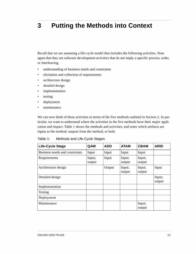
We can now think of these activities in terms of the five methods outlined in Section 2. In par-ticular, we want to understand where the activities in the five methods have their major appli-cation and impact. Table 1 shows the methods and activities, and notes which artifacts are inputs to the method, outputs from the method, or both.
Table 1: Methods and Life-Cycle Stages
Life-Cycle Stage QAW ADD ATAM CBAM ARID
Business needs and constraints Input Input Input Input
Requirements Input; output
Input Input; output
Input; output
Architecture design Output Input; output
Input; output
Input
Detailed design Input; output
Implementation
Testing
Deployment
Maintenance Input; output

14 CMU/SEI-2003-TN-026
Not surprisingly, the methods focus on the life-cycle stages and artifacts that appear earlier in a project’s lifetime. The methods have this early focus because they are architecture-centric techniques, and an architecture is the blueprint for a system. Once a project is in implementa-tion, testing, deployment, or maintenance, the architecture has been largely decided on, either explicitly or implicitly.4 This principle has one exception: the CBAM may apply to mainte-nance activities, because in maintenance, making substantial system changes that affect the architecture are possible. In Table 1, the “Input; output” annotation for this stage in CBAM indicates this possibility.
Since the ATAM was the first of these methods to be developed, and in a stand-alone fashion, it was forced to undertake activities that actually belong, in concept, to requirements elicita-tion, design, or maintenance. To analyze an existing software architecture using the ATAM, one needs to understand the business needs that motivate the system, the requirements, the existing design decisions, and the anticipated changes to the system during the maintenance phase. This duplication of effort is appropriate for a method conducted by an outsider, but is inappropriate if the methods are seen as integral to an organization’s normal development pro-cess.
The QAW was developed in recognition that some of this effort could be done earlier in the life cycle and obviate the need for the early ATAM steps. This work was a form of early tailor-ing. In Section 4, we look at placing the methods’ activities in the context of an SDLC, which is a first step towards identifying other opportunities for tailoring and allowing organizations to determine how they want to augment their SDLC with architecture-based activities.
4. Note that after the architecture is defined, documented, and analyzed, it still must be enforced in downstream software de-velopment activities. Traditional processes must be altered to include architecture-centric activities, such as implementingthe system based on the architecture and ensuring that the implementation (during development and maintenance) con-forms to the architecture.

CMU/SEI-2003-TN-026 15
4 Integrating the Methods with an Organization’s Life Cycle
Given the information in Table 1, we can think about placing these methods into a software development organization’s own life cycle. While any such method could be included verba-tim (since, as stated above, these methods were meant to stand alone and be performed by out-siders), the methods more likely will be tailored when adopted. In this section, therefore, we concentrate on each phase of the life cycle and the appropriate steps from the various architec-ture-centric methods that could augment and improve the enactment of that phase.
4.1 Business Needs and ConstraintsAlthough this topic is not often included in descriptions of SDLC models, it has a profound impact on project outcomes and on any architecture-centric approach to system building. For this reason, we strongly believe that an organization should include it explicitly in any SDLC discussion. Software development projects usually are created in response to business needs and are promoted by a stakeholder or a group of stakeholders within an organization. The busi-ness needs influence many of the system’s functions as well as its quality attribute require-ments. The business needs also might imply other architectural constraints, such as requiring interoperability among systems, adhering to standards, and maintaining consistency with other user interfaces.
The business needs and constraints must be captured in a document or presentation that details the business issues, the origin of each issue, any rationale behind it, and the expected benefits. (For an example, refer to Evaluating Software Architectures: Methods and Case Studies [Clements 02].) The document also might capture any history of the project, the business envi-ronment, the stakeholder community, and any business or technical constraints. This document then serves as the foundation for a plethora of decisions that occur later in a project’s lifetime. For example, scenarios and design decisions can be traced back to business decisions. Design tradeoffs inevitably will occur and they, too, must be motivated by business priorities. And when development priorities are being established, the cost-benefit analysis that directs the future of the project must be linked explicitly back to the business goals.
The business goals constitute an important input and starting point for all the architecture-cen-tric methods shown in Table 1, except for ARID, which focuses on analyzing the usability of the design from a programmer’s perspective.
16 CMU/SEI-2003-TN-026
4.2 RequirementsRequirements elicitation, validation, documentation, and analysis traditionally have focused more on specifying what a system should do (the functional requirements) than on how the system should function (the nonfunctional, or quality, requirements). The IEEE Standard 830-1998 for software requirements specifications, for example, mentions performance, reliability, availability, maintainability, portability, and security as attributes to be considered, but the focus is clearly on functional aspects of the system [IEEE 98].
The architecture-centric techniques that we discussed in Section 2, by contrast, focus almost entirely on quality attributes and quality attribute requirements. Why? Because an architecture is the single greatest determining factor in the achievement of a complex system’s quality attributes. (Bass and associates discuss this point in detail [Bass 03].) A system can achieve the same functionality using a myriad of different architectures; the changes occur in the qual-ity attributes among those architectures. For example, systems are often rearchitected, not to change their functionality, but rather to change their quality attributes: to make them faster, more portable, or more modifiable. In short, quality attribute requirements drive the architec-ture of successful complex systems.
In current SDLCs, functional requirements are described in a variety of ways, most commonly employing use cases. Use cases describe an interaction between the system and its environ-ment. Quality requirements cannot be adequately captured with just use cases. To address this shortcoming, the architecture-centric methods described in this report employ six-part scenar-ios, as introduced in Section 2.1. A six-part scenario captures
• a stimulus—some condition that is affecting the system
• a response—the system activity that results from the stimulus
• a stimulus source—the entity that generated the stimulus
• an environment—the condition under which the stimulus occurred
• a stimulated artifact —the system artifact that was directly affected by the stimulus
• a response measure—the measure by which the system’s response is evaluated
The architecture-centric methods elicit and capture quality attribute scenarios in a variety of ways—namely, by using general scenarios, utility trees, and scenario brainstorming.
General scenarios are quality-attribute-specific templates for creating six-part scenarios [Bass 01]. For each quality attribute, a general scenario lists the possible values for each of the six parts. Specific scenarios are then created by selecting values for each of the six parts, and by adding system- and context-specific details. General scenarios provide a system-independent checklist for quality attribute requirements and thus ensure that these requirements are covered completely in the elicited scenarios.
CMU/SEI-2003-TN-026 17
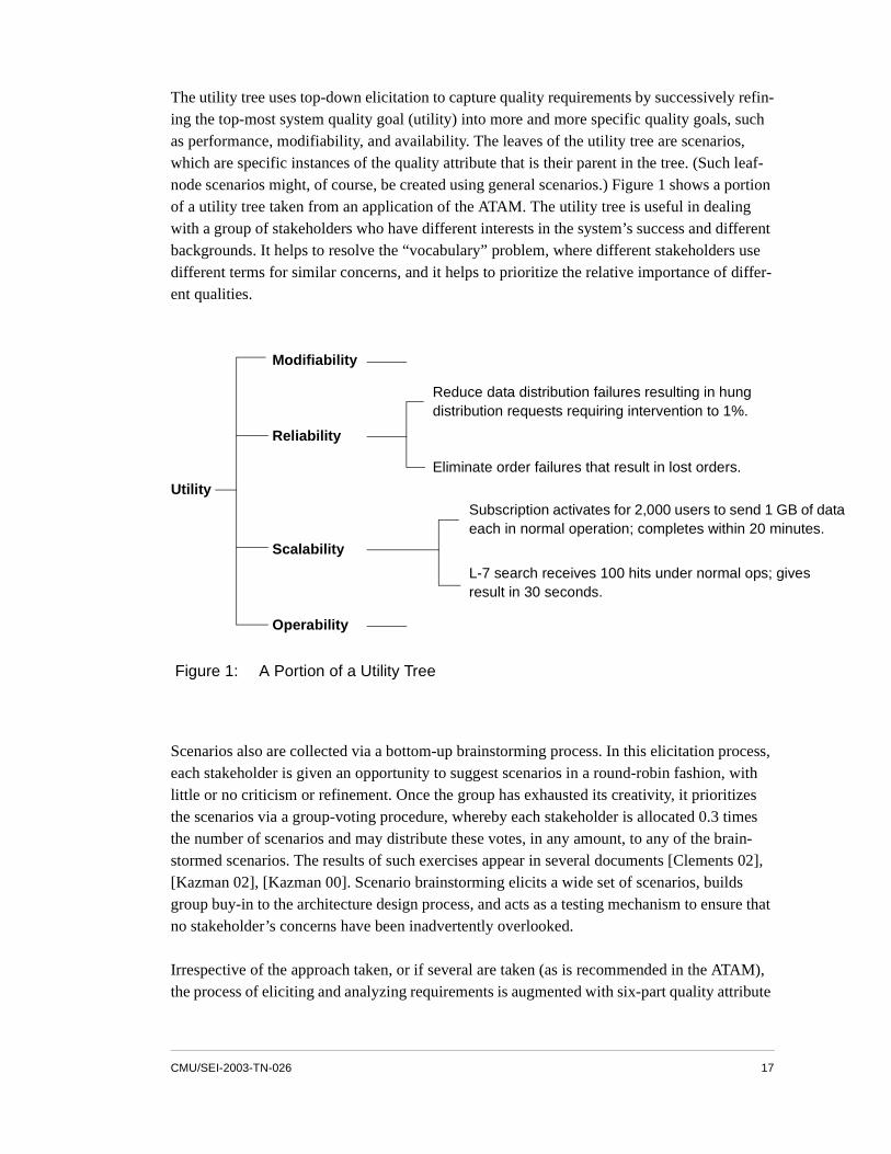
The utility tree uses top-down elicitation to capture quality requirements by successively refin-ing the top-most system quality goal (utility) into more and more specific quality goals, such as performance, modifiability, and availability. The leaves of the utility tree are scenarios, which are specific instances of the quality attribute that is their parent in the tree. (Such leaf-node scenarios might, of course, be created using general scenarios.) Figure 1 shows a portion of a utility tree taken from an application of the ATAM. The utility tree is useful in dealing with a group of stakeholders who have different interests in the system’s success and different backgrounds. It helps to resolve the “vocabulary” problem, where different stakeholders use different terms for similar concerns, and it helps to prioritize the relative importance of differ-ent qualities.
Scenarios also are collected via a bottom-up brainstorming process. In this elicitation process, each stakeholder is given an opportunity to suggest scenarios in a round-robin fashion, with little or no criticism or refinement. Once the group has exhausted its creativity, it prioritizes the scenarios via a group-voting procedure, whereby each stakeholder is allocated 0.3 times the number of scenarios and may distribute these votes, in any amount, to any of the brain-stormed scenarios. The results of such exercises appear in several documents [Clements 02], [Kazman 02], [Kazman 00]. Scenario brainstorming elicits a wide set of scenarios, builds group buy-in to the architecture design process, and acts as a testing mechanism to ensure that no stakeholder’s concerns have been inadvertently overlooked.
Irrespective of the approach taken, or if several are taken (as is recommended in the ATAM), the process of eliciting and analyzing requirements is augmented with six-part quality attribute
Figure 1: A Portion of a Utility Tree
Utility
Modifiability
Operability
Reliability
Subscription activates for 2,000 users to send 1 GB of data each in normal operation; completes within 20 minutes.
L-7 search receives 100 hits under normal ops; gives result in 30 seconds.
Reduce data distribution failures resulting in hung distribution requests requiring intervention to 1%.
Eliminate order failures that result in lost orders.
Scalability

18 CMU/SEI-2003-TN-026
scenarios that are architecturally relevant. These scenarios will inform and direct subsequent design and analysis activities.
Integrating architecture-centric methods into an existing SDLC requires explicit elicitation, documentation, and analysis of quality attribute scenarios. Requirements serve as the key bridge between a system’s business goals and its architecture, and thus are listed as being an input for the QAW, ADD, the ATAM, and CBAM in Table 1, and are an output of the QAW, ATAM, and CBAM.
4.3 Architecture DesignArchitecture design often is done implicitly in existing SDLCs. Most development processes do not make it an explicit activity, with defined milestones, scheduled reviews, and regular documentation. As a result, the architecture design of a system is frequently emergent. To encourage a more disciplined approach to this design, organizations must make it a regular part of their SDLC.
From the perspective of our architecture-centric methods, such action requires an organization to employ an explicit architecture design activity such as the ADD method [Bass 03]. This activity has several consequences for a development project:
• An architecture design must be created. The process of creating an architecture is com-plex, involving the satisfaction of many competing demands. The ADD method addresses this complexity in part by using prepackaged architectural patterns [Buschmann 96] and tactics [Bachmann 03].
• The architecture must be properly documented. The ADD method recommends that the architecture be documented in at least three views: module decomposition, concurrency, and deployment. The book titled Documenting Software Architecture: Views and Beyond provides guidelines for documenting these views [Clements 03].
The architecture must be analyzed for suitability with respect to the quality attributes and the business goals from which these quality attributes are derived. Such an analysis might follow the ATAM, CBAM, or some other technique.
Each of these bulleted points is relevant to Table 1. In this table, we show the architecture design as an output of ADD, an input to ARID, and both an input to and an output from the ATAM and CBAM. From a life-cycle perspective, however, each of these points typically rep-resents a new activity in an organization’s SDLC, one that was not part of the organization’s previous way of building systems. Thus the “architecture-aware” SDLC must be expanded to include these activities, as required, in the organization’s standard development process.
CMU/SEI-2003-TN-026 19
For example, the ATAM has been used many times on existing systems to assess the fitness of the architecture for both its current envisaged use and its future use. During an ATAM evalua-tion, scenarios are collected in three categories:
• anticipated uses of the systems (use case scenarios)
• anticipated changes to the systems (growth scenarios)
• unanticipated stresses to the systems (exploratory scenarios)
These scenarios are used to understand and analyze the architecture. Any architecture-aware SDLC should collect these scenarios on an ongoing basis and periodically analyze the archi-tecture to understand its response to these scenarios. In this way, architectural defects can be found as a normal part of the design process.
4.4 Detailed DesignDuring the detailed design phase, an ARID review also can take place, to ensure that the implementers can use the detailed design and architecture. Table 1 reflects this activity by showing the architecture as an input and the detailed design as both input to and output from an ARID execution. An ARID activity accomplishes much the same purpose as usability test-ing of the graphical user interface (GUI) with end users. Adding this step into the SDLC ensures that the architecture and the detailed designs flowing from it are indeed usable by the developers to implement their tasks, as defined by the collected scenarios.
4.5 MaintenanceThe maintenance phase of a product’s life cycle is typically the longest phase and, in the end, the most costly. This phase also carries substantial risk, for if the wrong decisions are made when evaluating the product, it will fail to meet its stakeholders’ needs and thereby ultimately fail as a system. The architecture-centric methods described in Section 2 can have a substantial positive impact on a product’s evolutionary path by lowering the risk of making inappropriate architectural decisions.
As the product grows and evolves, architectural changes inevitably ensue. These changes are motivated by new scenarios, representing the stakeholders’ new or changed business goals. The organization must therefore redesign and modify the architecture to meet these new goals, as exemplified by the new scenarios. The organization may, at this point, invoke the ADD method to design appropriate architectural responses to the new challenges.
The architecture’s fitness to meet its new goals and the architectural changes that result from the ADD activity should, of course, be reviewed. To this end, the organization should invoke

20 CMU/SEI-2003-TN-026
an architectural analysis activity, such as that embodied in the ATAM, to understand the risks, sensitivities, and tradeoffs embodied in the existing and proposed architectures.
Finally, the organization must make a set of decisions. Every project has a finite budget, and typically, all the desired and proposed changes cannot be funded or, even if they could, they cannot be implemented simultaneously by the development team. So the organization must make choices by prioritizing the proposed architectural strategies.
To make these choices, the organization can employ some of the CBAM steps. The previously collected scenarios can be augmented with a range of response values. Associated with each one of these responses is a utility value. Given this information, the organization can estimate the expected benefits of all architectural strategies and then determine the costs of these strate-gies. With costs and benefits understood, the organization can make informed decisions among the proposed architectural strategies based on the metric of ROI.
For this reason, the CBAM is shown with “maintenance” as both an input and an output in Table 1, which is an awkward way of saying that maintenance plans and activities can be an input to the CBAM and will be tempered by the results of the CBAM.
CMU/SEI-2003-TN-026 21
5 Summary
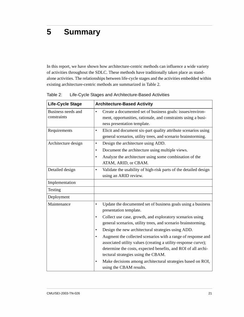
In this report, we have shown how architecture-centric methods can influence a wide variety of activities throughout the SDLC. These methods have traditionally taken place as stand-alone activities. The relationships between life-cycle stages and the activities embedded within existing architecture-centric methods are summarized in Table 2.
Table 2: Life-Cycle Stages and Architecture-Based Activities
Life-Cycle Stage Architecture-Based Activity
Business needs and constraints
• Create a documented set of business goals: issues/environ-ment, opportunities, rationale, and constraints using a busi-ness presentation template.
Requirements • Elicit and document six-part quality attribute scenarios using general scenarios, utility trees, and scenario brainstorming.
Architecture design • Design the architecture using ADD.
• Document the architecture using multiple views.
• Analyze the architecture using some combination of the ATAM, ARID, or CBAM.
Detailed design • Validate the usability of high-risk parts of the detailed design using an ARID review.
Implementation
Testing
Deployment
Maintenance • Update the documented set of business goals using a business presentation template.
• Collect use case, growth, and exploratory scenarios using general scenarios, utility trees, and scenario brainstorming.
• Design the new architectural strategies using ADD.
• Augment the collected scenarios with a range of response and associated utility values (creating a utility-response curve); determine the costs, expected benefits, and ROI of all archi-tectural strategies using the CBAM.
• Make decisions among architectural strategies based on ROI, using the CBAM results.

22 CMU/SEI-2003-TN-026
While each of these steps involves additional overhead as compared with the traditional, non- architecture-aware SDLC, this additional encumbrance is more than repaid by having an archi-tecture that is designed, documented, analyzed, and evolved in a disciplined way. The alterna-tive to adding these steps to the SDLC is for an organization to choose a chaotic approach to architecture design.
Describing these architecture-based activities constitutes a first step towards creating tailor-able architecture methods. Future work will include examples of integrating architecture-cen-tric methods, both with each other and into an organization’s SDLC.
CMU/SEI-2003-TN-026 23
References
[Bachmann 03] Bachmann, Felix; Bass, Len; & Klein, Mark. Deriving Architec-tural Tactics: A Step Toward Methodical Architectural Design (CMU/SEI-2003-TR-004, ADA413644). Pittsburgh, PA: Soft-ware Engineering Institute, Carnegie Mellon University, 2003. <http://www.sei.cmu.edu/publications/documents/03.reports/03tr004.html>.
[Barbacci 03] Barbacci, Mario R.; Ellison, Robert; Lattanze, Anthony J.; Stafford, Judith A.; Weinstock, Charles B.; & Wood, William G. Quality Attribute Workshops, Third Edition (CMU/SEI-2003-TR-016). Pittsburgh, PA: Software Engineering Institute, Carnegie Mellon University, 2003. <http://www.sei.cmu.edu/publications/documents/03.reports/03tr016.html>.
[Bass 01] Bass, Len; Klein, Mark; & Moreno, Gabriel. Applicability of General Scenarios to the Architecture Tradeoff Analysis Method (CMU/SEI-2001-TR-014, ADA396098). Pittsburgh, PA: Soft-ware Engineering Institute, Carnegie Mellon University, 2001. <http://www.sei.cmu.edu/publications/documents/01.reports/01tr014.html>.
[Bass 03] Bass, Len; Clements, Paul; & Kazman, Rick. Software Architec-ture in Practice, Second Edition. Boston, MA: Addison-Wesley, 2003.
[Buschmann 96] Buschmann, Frank; et al. Pattern-Oriented Software Architec-ture, Volume 1: A System of Patterns. Chichester, NY: Wiley and Sons, 1996.
URLs valid as of the publication date of this document
24 CMU/SEI-2003-TN-026
[Clements 00] Clements, Paul C. Active Reviews for Intermediate Designs (CMU/SEI-2000-TN-009, ADA383775). Pittsburgh, PA: Soft-ware Engineering Institute, Carnegie Mellon University, 2000. <http://www.sei.cmu.edu/publications/documents/00.reports/00tn009.html>.
[Clements 02] Clements, Paul; Kazman, Rick; & Klein, Mark. Evaluating Soft-ware Architectures: Methods and Case Studies. Boston, MA: Addison-Wesley, 2002.
[Clements 03] Clements, Paul; Bachmann, Felix; Bass, Len; Garlan, David; Ivers, James; Little, Reed; Nord, Robert; & Stafford, Judith. Doc-umenting Software Architectures: Views and Beyond. Boston, MA: Addison-Wesley, 2003.
[IEEE 98] Institute of Electrical and Electronics Engineers. IEEE Recom-mended Practice for Software Requirements Specifications (IEEE-Std-830-1998). Piscataway, NJ: IEEE Computer Press, 1998.
[Kazman 96] Kazman, Rick; Abowd, Gregory; Bass, Len; & Clements, Paul. “Scenario-Based Analysis of Software Architecture.” IEEE Soft-ware 13, 6 (Nov. 1996): 47-55.
[Kazman 99] Kazman, Rick; Barbacci, Mario; Klein, Mark; Carrière, Jeromy; & Woods, Steven G. “Experience with Performing Architecture Tradeoff Analysis,” 54-63. Proceedings of the 21st International Conference on Software Engineering (ICSE 99). Los Angeles, CA, May 16 - 22, 1999. New York, NY: Association for Comput-ing Machinery, 1999.
[Kazman 00] Kazman, Rick; Klein, Mark; & Clements, Paul. ATAM: Method for Architecture Evaluation (CMU/SEI-2000-TR-004, ADA382629). Pittsburgh, PA: Software Engineering Institute, Carnegie Mellon University, 2000. <http://www.sei.cmu.edu/publications/documents/00.reports/00tr004.html>.
CMU/SEI-2003-TN-026 25
[Kazman 01] Kazman, Rick; Asundi, Jai; & Klein, Mark. “Quantifying the Costs and Benefits of Architectural Decisions,” 297-306. Pro-ceedings of the 23rd International Conference on Software Engi-neering (ICSE 2001). Toronto, Ontario, Canada, May 12 - 19, 2001. Los Alamitos, CA: IEEE Computer Society, 2001.
[Kazman 02] Kazman, Rick; Asundi, Jai; & Klein, Mark. Making Architecture Design Decisions: An Economic Approach (CMU/SEI-2002-TR-035, ADA408740). Pittsburgh, PA: Software Engineering Insti-tute, Carnegie Mellon University, 2002. <http://www.sei.cmu.edu/publications/documents/02.reports/02tr035.html>.

26 CMU/SEI-2003-TN-026

REPORT DOCUMENTATION PAGE Form ApprovedOMB No. 0704-0188
Public reporting burden for this collection of information is estimated to average 1 hour per response, including the time for reviewing instructions, searching existing data sources, gathering and maintaining the data needed, and completing and reviewing the collection of information. Send comments regarding this burden estimate or any other aspect of this collection of information, including suggestions for reducing this burden, to Washington Headquarters Services, Directorate for information Operations and Reports, 1215 Jefferson Davis Highway, Suite 1204, Arlington, VA 22202-4302, and to the Office of Management and Budget, Paperwork Reduction Project (0704-0188), Washington, DC 20503.
1. AGENCY USE ONLY (leave blank) 2. REPORT DATE
September 2003
3. REPORT TYPE AND DATES COVERED
Final
4. TITLE AND SUBTITLE
A Life-Cycle View of Architecture Analysis and Design Methods
5. FUNDING NUMBERS
F19628-00-C-0003
6. AUTHOR(S)
Rick Kazman, Robert L. Nord, Mark Klein7. PERFORMING ORGANIZATION NAME(S) AND ADDRESS(ES)
Software Engineering InstituteCarnegie Mellon UniversityPittsburgh, PA 15213
8. PERFORMING ORGANIZATIONREPORT NUMBER
CMU/SEI-2003-TN-026
9. SPONSORING/MONITORING AGENCY NAME(S) AND ADDRESS(ES)
HQ ESC/XPK5 Eglin StreetHanscom AFB, MA 01731-2116
10. SPONSORING/MONITORING AGENCY REPORT NUMBER
11. SUPPLEMENTARY NOTES
12.a DISTRIBUTION/AVAILABILITY STATEMENT
Unclassified/Unlimited, DTIC, NTIS12.b DISTRIBUTION CODE
13. ABSTRACT (maximum 200 words)
Many architecture-centric analysis and design methods have been created in the past 10 years at the Software Engineering Institute, beginning with the Software Architecture Analysis Method (SAAM). The SAAM inspired the creation of other methods, namely the Architecture Tradeoff Analysis MethodSM, the Quality Attribute Workshop, the Cost-Benefit Analysis Method, Active Reviews for Intermediate Designs, and the Attribute-Driven Design method.
As these methods become more widespread, more widely adopted, and integrated into the software development life cycle, organizations inevitably will want to tailor them. Consequently, organizations that wish to include quality-attribute-based requirements, explicit architecture design, and architecture analysis in their software development life cycles will be best served if they can do so “organically.” The steps and artifacts of the five methods listed above, therefore, may require tailoring, blending, and, in some cases, removal when integrated into an existing life cycle.
This report examines these methods and activities to understand their commonalities and relationships to life-cycle changes, and proposes a means of tailoring the activities so that they can fit more easily into existing life-cycle models.
14. SUBJECT TERMS
architecture, design method, software development life cycle, SDLC, quality attribute requirements, architecture-centric, design analysis
15. NUMBER OF PAGES
3816. PRICE CODE
17. SECURITY CLASSIFICATION OF REPORT
UNCLASSIFIED
18. SECURITY CLASSIFICATION OF THIS PAGE
UNCLASSIFIED
19. SECURITY CLASSIFICATION OF ABSTRACT
UNCLASSIFIED
20. LIMITATION OF ABSTRACT
UL
NSN 7540-01-280-5500 Standard Form 298 (Rev. 2-89)Prescribed by ANSI Std. Z39-18298-102