Embed Size (px)
Citation preview
A Laser Based Alignment System for the CLIC project
Guillaume SternCLIC workshop at CERN
January 28, 2015

2
Outline
• Introduction• Description of the laser alignment system• Challenge of the PhD thesis• Experiment results• Conclusion

3
CLIC alignment• Components need to be pre-aligned before
beam based alignment
• Pre-alignment strategy– Fiducialisation of components and girders– Initial alignment of the components on the girders– Active alignment system using sensors and actuators
Component Pre-alignment requirements
Main linac component 14-17 µm
Main linac reference points 10 µm
Beam Delivery System (BDS) 10 µm

4
Problem
• Existing systems (e.g. based on stretched wire) not fully satisfying because of cost, difficult implementation
• Existing systems to be compared with a system based on different principle

5
Proposal of solution
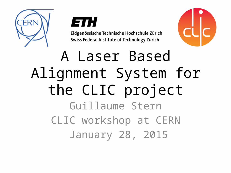
• Laser beam as straight line reference• Camera combined with open/close shutter to
measure distance between laser beam and components to be aligned
• Project name: LAMBDA project (Laser Alignment Multipoint Based Design Approach)
6
Alignment principle
7
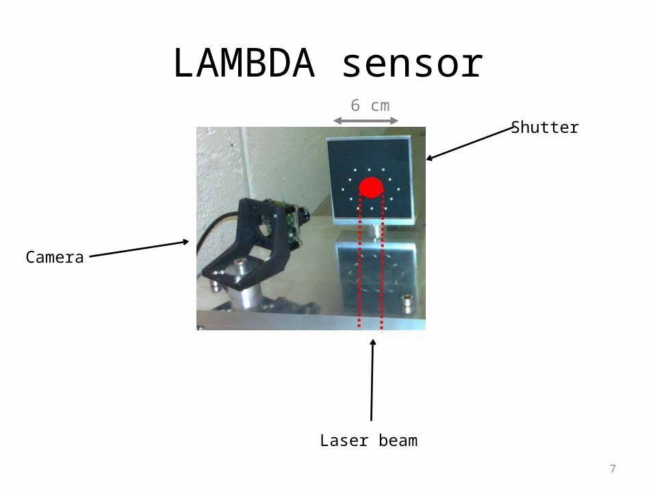
LAMBDA sensor
Camera
Laser beam
Shutter6 cm
8
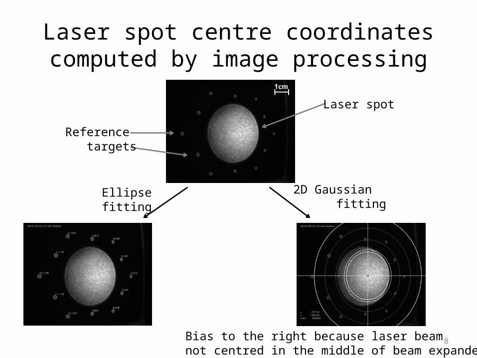
Laser spot centre coordinates computed by image processing
Reference targets
Laser spot
Ellipsefitting
2D Gaussian fitting
Bias to the right because laser beam not centred in the middle of beam expander

9
LAMBDA sensor requirements
• Compact• Compatible with its environment• Low cost• Measurement repeatability 1 µm• Measurement accuracy 5 µm

10
Challenge
• Determine sources of uncertainty– Laser beam as straight line reference?– Measurement of laser spot on shutter?– Sensor in its environment?
• Estimate and minimise uncertainty by experiments and simulations
11
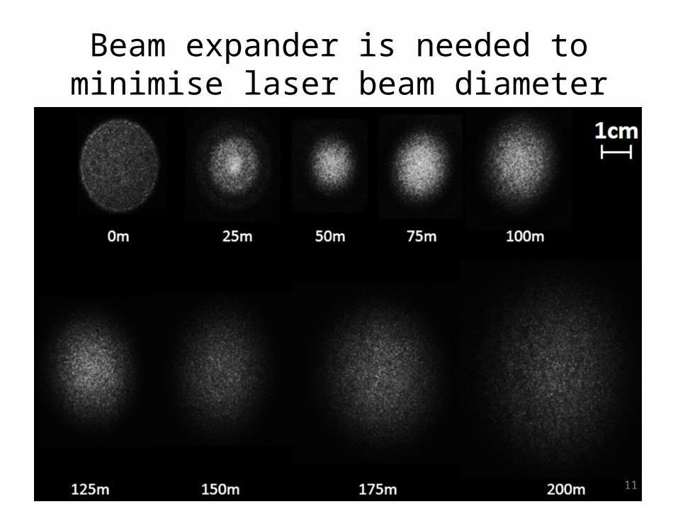
Beam expander is needed to minimise laser beam diameter

12
Laser pointing stability decreases with distance of propagation
Laser beam propagates4 times over 50 m by means of 3 mirrors

13
Vacuum pipe is needed to increaselaser pointing stability
Laser beam propagates3 times over 12 m by means of 2 mirrors
Comparison at 35 m:Air: st. dev. < 200 µmVacuum: st. dev. < 8 µm

14
Shutter type Picture Flatness Standard deviation laser spot(distance of propagation: 3m)
Paper 30..110 µm < 5 µm
Ceramic 36-37 µm < 6 µm
Metal 15..16 µm < 12 µm
Ceramic shows a good compromise between paper and metal

15
Ongoing experiment: laser pointing stability w.r.t. shutter repositioning
Shutter closed Shutter half way Shutter open
6 cm
16
Conclusion
• Laser based alignment system studied to align magnets with 10 µm accuracy over 200 m
• Sensor = camera + open/close shutter• Lessons learnt from experiments – Beam expander and vacuum pipe needed– Ceramic shutter good compromise
• Next steps– Experiments on shutter repositioning– Simulations to complete the experiments– Calibration protocol for sensor– Thesis report