Embed Size (px)
Citation preview

DES 8100/1
it)1.
College of Aeronautics
AIRCRAFT DESIGN
A LARGE ADVANCED FREIGHT AIRCRAFT
Dr. ►1.P. Fielding
F-81

111111111,1I1111111111191111119111111,111111 PAGE
1. Introduction 2
2. Specification 2
3. Configuration and Design Requirements 3
4. Geometry 4
5. Powerplants 8
6. Masses, Centres of Gravity and Mom?nts of Inertia. 9
7. Aerodynamic Information 9
8. Load Distribution 11
INDEX
TABLES
1. Mass Breakdown
2. Moments of Inertia - Civil Version
3. Proposed Flight Pattern Distribution - Civil.
4. Delay Rate Targets for Individual Systems
FIGURES
1. General Arrangement
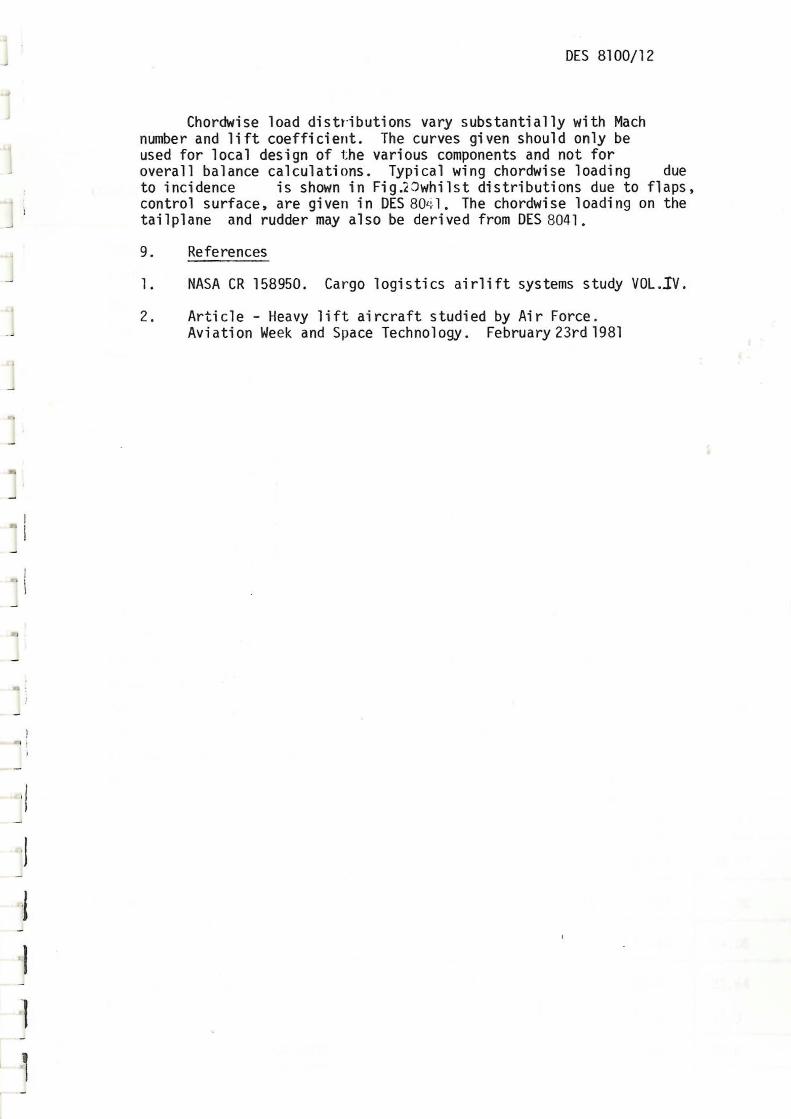
2. Fuselage Layout - Civil
3. Wing and Tail Geometry
4. Aerofoil and Control Sections
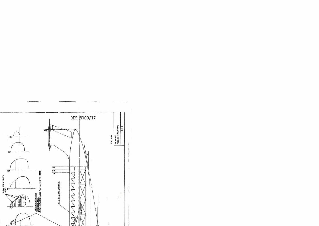
5. Fuselage Alterations for Military Version
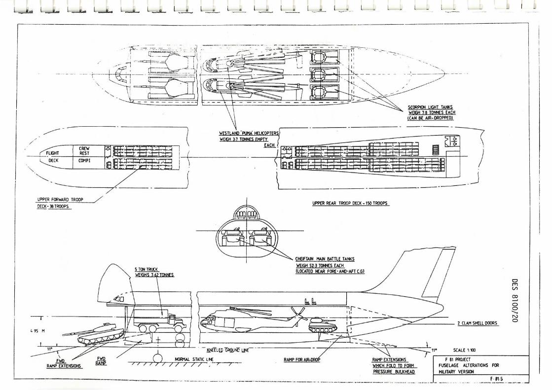
6. Level Speed Envelope
7. Payload - Range Envelope
8. Low Speed Lift Curve Slopes
9. Lift Curve Slope Variation with Mach No.
10. Variation of Wing Aero Centre Across Span
11. Variation of Tailplane Aero Centre Across Span
12. Variation of Fin Aero Centre Across Span
13. Rolling Derivatives ft and
14. Downwash at Tail
15. Wing Spanwise Load Distribution due to Incidence
16. Wing Spanwise Load Distritution due to Flaps and Ailerons
17-18 Tailplane Fin and Rudder Spanwise Load Distribution
19. Fuselage Lift Distribution
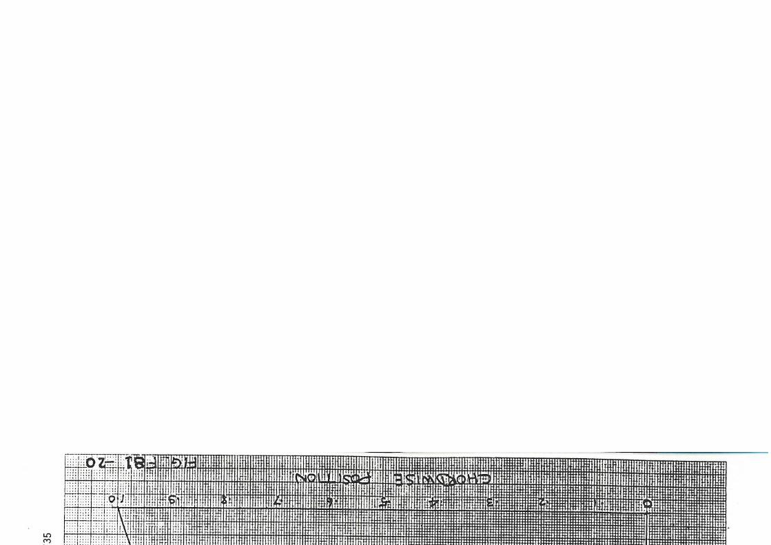
20. Wing Chordwise Load Distribution
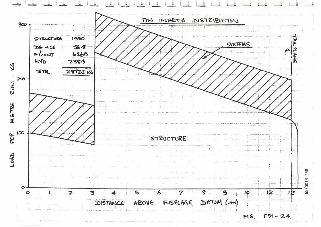
21-24 Fuselage, Wing, Tailplane and Fin Inertia Distribution
25 Freight Loading Diagram
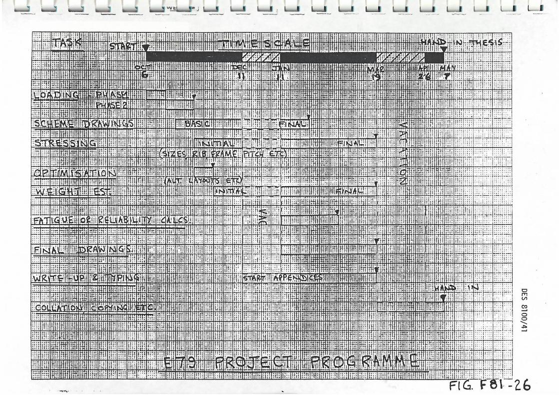
26 Project Programme.
1
I
1
1

DES 8100/2
1. Introduction
Commercial air freightoperations have grown in importance in recent years, due mainly to cost reductions caused by increasing aircraft and freight-terminal efficiencies. The bulk of this traffic is carried in the underfloor holds of wide-body passenger aircraft, but there is a significant sector of the market served by 'dedicated' freighters such as the 747F and DC8-63F. These aircraft are often equipped with standard containers and pallets which are loaded at factories or freight depots. The largest and most efficient container is the 8 ft x 8 ft x 20 ft size
NASA felt the need to study the air-freight market and commissioned the extensive C.L.A.S.S. study (Ref.1). This report suggested that significant operating cost savings would be required, together with improved ground interfaces, to make more inroads into the surface transport market.
It studied the economics of aircraft derived from current types, together with new designs. The former was more immediately attractive, but a market existed for new aircraft from the mid 1990's.
The most attractive new type would be a long range aircraft with payload in the 75 to 165 ton range. The lower size aircraft was slightly more economic, but would pose grave airport frequency saturation problems and therefore a larger aircraft was preferable. Air-craft much above the 165 ton class however, would lead to development costs higher than the market could stand.
An aircraft of about 165 tons payload seemed to be a good solution which could be made more attractive if it were designed to satisfy both civil and military requirements, thus spreading development costs. This philosophy was aimed at during the design of the Lockheed C-141 but too much emphasis was placed on military properties and no civil versions were sold. This should be avoided on a new design which should be capable of augmenting and partially replacing current fleets of 747F, DC10 CF and Lockheed C-5A aircraft.
It was decided to study such an aircraft with the main emphasis being on civil operations with modifications such as a kneeling undercarriage as military options. A specification was derived from refs. 1 and 2 together with information about current freighter aircraft which is shown in section 2 below:-
2. Specification
a) The Range with maximum payload should be 4,000 n. miles with reserves.
b) The Payload should be in the range 330-390,000 lb (150-175,000 kgs) CiviT-65iFitors would use 8 x 8 x 20 ft containers with provision for a height extension to 10 ft.
Military payloads would include most of the major equipment. Typical extremes in size and weight are:-
1) Weight. Chieftain Main battle tank (52.3 tonnes) 2) Length 175 mm self propelled gun (11.3)m 3) Height Puma helicopter rotor to retracted
undercarriage (13.2 ft {4 metres})

DES 8100/3
cl Field Performance in the civil version should be similar to that of the 747F:-
Take off to 35 ft = 11,000 ft (3350 m) Landing = 7,000 ft (2130 m)
The runway load classification number should be 87 on a 20in pavement. To meet commercial engine-out climb gradient.
d) Speed
Cruise Mach numbers in the 0.75-0.8 range
e) Technology
Technology that is likely to be available by the mid 1990's is to be used which should include:-
i) Advanced wing sections ii) "Active" controls. iii) Some composite materials iv) More fuel efficient engines v) Lighter weight systems.
f) Noise
To achieve current noise requirements.
g) Costs
The aircraft first costs should be $132 x 106 (US)in 1994 with direct operating costs 30% below those of 747 Fs.
3. Configuration and Design Requirements
A general arrangement drawing is shown in FigF81-1 and some points are discussed below:-
3.1 Wing
A moderate sweepback combined with a relatively thick supercritical wing section enable cruise Mach numbers in the region of 0.75 to be achieved. The aspect ratio is 11 and there is sufficient fuel tankage in the wing for a range of 4000 n. miles with reserves. The very high aspect ratio improves fuel burn and airfield performance. The large bending moments produced by such a wing are alleviated by "active" 'ailerons which modify the airload distribution. Single-slotted Fowler flaps, moderate wing loading, spoilers and the high aspect ratio give adequate field performance which may be augmented by leading-edge slats for military operations.
3.2 Fuselage
The aircraft uses an extremely large fuselage. The main freight hold has a parallel section wide enough to accommodate three 8' x 8' x 20' containers side by side together with two walk ways. The elliptical section gives a maximum height of 10 ft at the corners of the compartment but 13.5 ft at the centre for bulky loads. The upper deck includes the flight deck, rest station, wing centre section and two compartments which can be used for LD-7 "igloo" containers or passengers. The normal freight loading is by

f
DES 8100/4
means of the large nose 'visor' door. In military versions this may be augmented by nose ramps which when combined with a kneeling undercarriage, give an 11° drive on ramp. Provision is also made for a rear ramp door for the air-dropping of military supplies.
If the aircraft were used in an all passenger role, high density capacity 1000 passengers on three floors.
3.3 Engines
The aircraft uses four wing-pod mounted RB211 - 524D engines which have good fuel consumption, performance and noise characteristics. It is envisaged that by the mid 1990's these engines or their derivatives should have their fuel consumption improved by 13%.
3.4 Design requirements
The aircraft is to be designed to meet BCAR requirements at the normal take off mass of 4358404. The design value of cruise speed VC is 173 m/s EAS or M = 0,75, whichever is the lesser. The corresponding values of the design diving speed VD = 187 m/s [AS and M =0.81 and these values are shown in fig.6 Av.P. 970 requirements are to be used where appropriate.
The airframe life is to be 60,000 hours with average flight duration of 5.75 hours . The cabin differential pressure of 0.58 bar ensures that the cabin altitude need never exceed 2.1 km. The range performance depends un the flight pattern used and is summarised in fig.7.
The undercarriage design vertical velocity of descent is 3.05 m/s. The aircraft mass a!sociated with particular flight patterns for fatigue loading purposes must be calculated as appropriate. A typical distribution of flight profiles is given in table 3.
Where appropriate the design of components should allow for the reliability requirements shown in table 4.
4. Geometry
4.1 Wing (See Fig. 3 )
Gross area 68d.9 m
Span 87.2 m
Aspect ratio 11.04
Root chord (centreline) 11.3 m
Tip chord (nominal) 4.5 m
Leading edge sweepback 27°
Sweep of 0.25c line 25°
Standard mean chord E 7.90 M

_l
DES 8100/5
Aerofoil section:-
root 15% thickness supercritical
tip 12.2%thickness supercritical
(See Figure 4 )
Wing body setting angle, rel. to chord line
Anhedral on 0.25c line
Location of 0.25 c aft of nose
Location of 0.25 E line, at centreline above datum
2°
5o
34.29 m
2.55 m
4.2 Ailerons (See Fig. 3 )
Type:- Round nose
Aileron chord/wing chord 0.25
Movement - + 200
Inboard end from aircraft centreline 33.48 m
Outboard end from aircraft centreline 42.28 m
4.3 Trailing edge flaps (See Fig. 4
Type:- Single slotted Fowler
Flap chord/wing chord
Take off flap angle
Landing flap angle
Inboard end of flap from C.
Outboard end of flap from CL
Wing chord flap extended/wing chord
4.4 Wing spoilers (See Fig. 3 )
)
0.30
25°
40°
6.52 m
33.48 m
1.15
Chord 10% of local chord
Movement max. relative to local top surface 60°
Inboard end relative to aircraft [ 6.52 m
Outboard end relative to aircraft E 33.48 m
Distance of spoiler leading edge from wing 35% of chord trailing edge

DES 8100/6
4.5 Tailplane (See Fig. 3 )
Gross area 73.8 m2
Span 18.0 m
Aspect ratio 4.39
Root chord (centreline) 5.8 m
Tip chord (nominal) 2.4 m
Sweepback of leading edge, approx. 31°
Sweep of 0.25 c line 25°
Aerofoil section:-
10% thickness symmetrical
(See Fig. 4 )
Dihedral Zero
Movement +8° -13'
Location of apex line aft of fuselage nose. 73.27 m
Vertical location above fuselage datum 12.0
4.6 Elevator (See Fig. 3)
Type:- Round nose
Elevator chord/tailplane chord
0.30
Movement -25°
4.7 Fin (See Fig. 3 )
Nominal area above fuselage datum (ignoring 114.66 m2 tip fairing)
Net area, above fuselage 80.44 m2
Height above datum 12.6 m
Nominal height above fuselage 9.4 m
Aspect ratio, based on nominal area 1.385
Aspect ratio, based on net area 1.098
Root chord, on fuselage datum 11.0 m
Tip chord (nominal) 7.2 m
Sweepback of leading edge, approx. 33°
Aerofoil section:- 12% thickness
(See Fig. 4
symmetrical
+20°
Distance of intersection of leading edge with fuselage datum, aft of fuselage nose. 66.73 m

DES 8100/7
4.8 Rudder (See Fig. 3 )
Type: Round nose
Rudder chord/fin chord
Height of rudder root at trailing edge, above datum
Height of rudder tip at trailing edge above datum
Movement
4.9 Fuselage (See Fig. 2 )
Overall length
Maximum width overall
Internal width on main hold floor
Internal width on upper deck floor
Maximum height of main hold
Maximum length of main hold
4.10 Undercarriage (See Fig. 2 )
Type:- Nosewheel with four main legs.
Wheelbase, to centre of main units
Track, to centre of outboard main bogie
Main undercarriage units
6 wheel bogie
Tyres: 1.245 m diameter by 0.432 m wide
Tyre pressure
Wheel track
Bogie wheelbase between adjacent axles
Static tyre closure
Maximum tyre closure
Centre of bogie aft of fuselage nose
Distance to centre of inboard bogie from
0.25
3.2 m
10.7 m
-T-20°
78.6 m
10.4 m
8.6 m
3.6 m
3.94 m
57.2 m
26.54 m
8.1 m
10.34 bar
1.28 m
1.5 m
0.11 m
0.324 m
37.34 m
Q
1.0 m

DES 8100/8
Nose undercarriage
Four wheels in line, rearwards retracting
Tyres 1.245 m diameter x 0.432 m wide
Tyre pressure 10.34 bar
Track of outer wheels 2.9 m
Location of leg aft of fuselage nose 10.8 m
5. Powerplants
Type: Rolls Royce RB211-524D bypass turbojet
Sea level static rating 235.75 kN
Installation: 4 underslung wing pods
Inboard powerplants
Distance of engine centreline below datum 0.15 m at front face
Distance of engine centreline from aircraft 14.85 m centreline at front face
Location of engine front face aft of 27.1 m fuselage nose
Maximum pod diameter 2.45 m
Total length of pod 5.1 m
Angle of pod datum 2.0° nose in
Sweepback of pylon leading edge 17° relative to fuselage datum
Sweepback of pylon trailing edge 13 5o relative to fuselage datum
Inclination of pylon to vertical 0°
Pylon chord at engine centreline 5.7 m
Pylon chord at wing datum 6.5 m
Pylon aerofoil section Symmetrical 12% thickness at 50%c
Outboard powerplants
Distance of engine (entreline below datum at front face
Distance of engine centreline from aircraft centreline at front face
Location of engine front face aft of fuselage nose
Remainder of powerplant information as for the inboard powerplants
1.1 m
25.3 m
32.17 m

DES 8100/9
5.1 Auxiliary power unit
Type:- Garrett Airesearch
APU datum below fuselage datum
APU position from fuselage nose
6. Masses, Centres of Gravity and Moments of Inertia
Design normal take off mass
Design maximum landing mass
Minimum flying mass
Operating empty mass
Maximum payload
Maximum fuel load
Mass breakdown - see Table 1.
Centres of Gravity at APS mass, relative to 0.25c and datum (Freight role)
Undercarriage retracted
Undercarriage extended
Centres of gravity range in flight
Moment of Inertia - see Table 2.
3.2 m
30.09 m
435840 kg
414048 kg
139368 kg
139005 kg
155690 kg
167980 kg
.[
t
0.31 m fwd 0.32 m above 0.07 m fwd 0.024 m above
0.2c to 0.43c
J
7. Aerodynamic Information
7.1 Lift characteristics
Maximum lift coefficient:-
Basic wing
Flaps at take-off setting
Flaps at landing setting
Slope of wing-body lift curve
Basic
Flaps deployed
1.34
2.04
2.31
4.917/rad
5.045/rad.

DES 8100/10
7.2 Drag characteristics
Drag polar:-
Cruise condition M = 0.75 and 10,670 m
CD
= 0.0194 + 0.034 C
Take off at sea level, undercarriage and flaps extended
CD
= 0.0425 + 0.034C + 0.053AC 2
Landing at sea level, undercarriage and flaps extended
CD
= 0.0715 + 0.034 C 2 + 0.053 ACL2
Where ACL
is increment in CL due to flap deflection.
7.3 Pitching Moment Characteristics (low speed)
Pitching moment coefficient at zero lift
Wing alone, CM0 -0.06
Increment due to body and nacelles, ACM -0.011
Pitching moment increment due to flaps:-
Take off setting, ACM -0.17
Landing setting, ACM -0.233
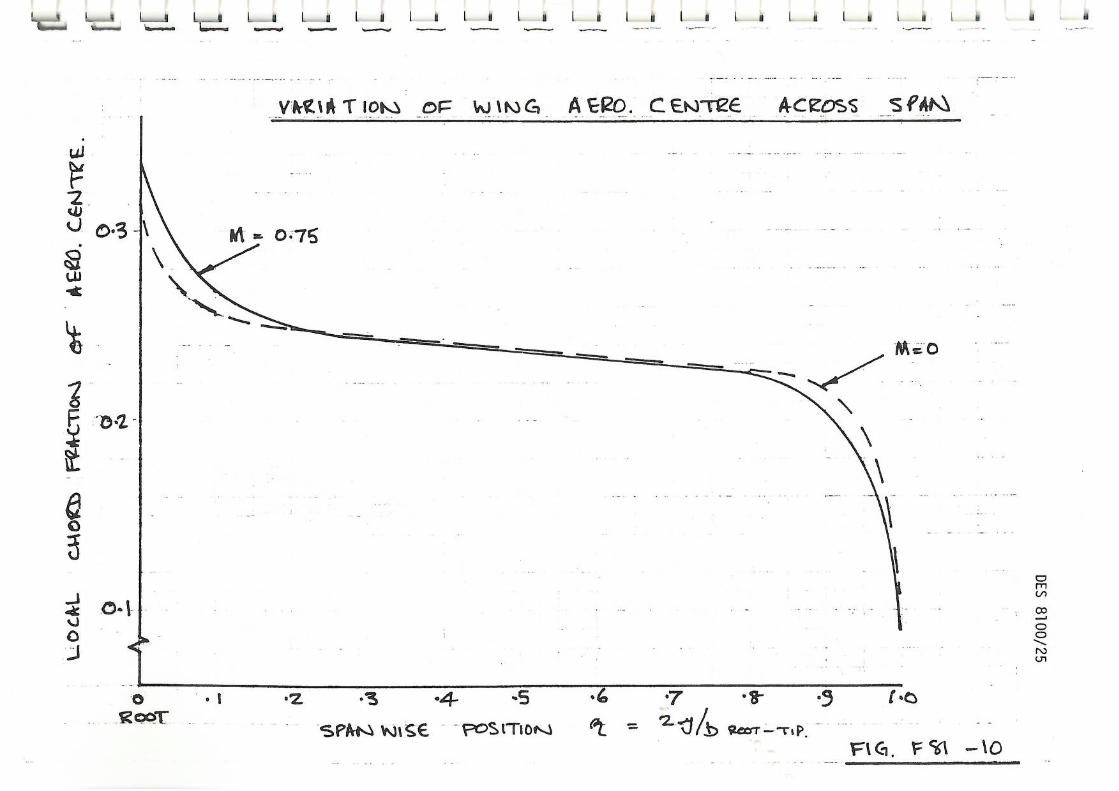
Location of overall wing-body aero centre
33.84 from fuselage nose, clean
(Forward shift due to basic fuselage 0.123 E
(Forward shift due to engine nacelles 0.02 C
Spanwise variation of basic wing aero centre Fig.
7 4 Control and Stabiliser Characteristics
Location of mean tailplane aero centre 76.67 m aft of fuselage nose
Spanwise variation of tailplane aero centre - see Fig. 11
Location of mean fin aenacentre aft 71.17 m of fuselage nose
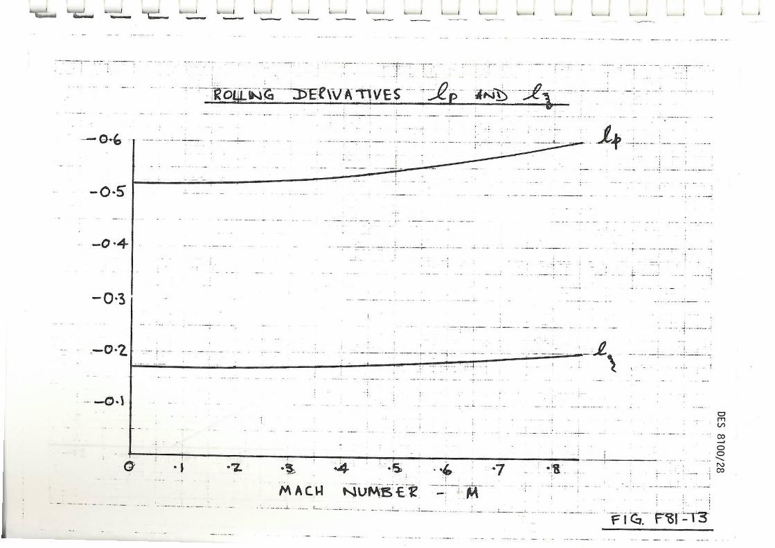
Rolling moment coefficient due to aileron,i - see Fig.13
Yawing moment coefficient due to aileron, n -0.011
DES 8100/11
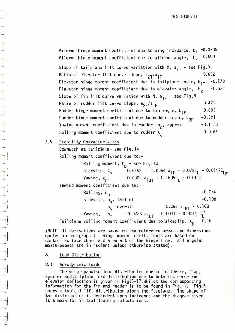
Aileron hinge moment coefficient due to wing incidence, bl -0.3706
Aileron hinge moment coefficient due to aileron angle, b2 0.699
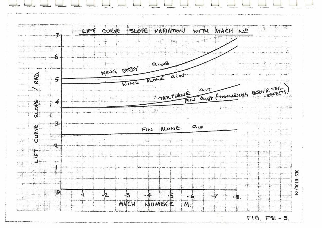
Slope of tailplane lift curve variation with M, au - see Fig.9
Ratio of elevator lift curve slope, a2T/a
1T 0.652
Elevator hinge moment coefficient due to tailplane angle, b1T -0.178
Elevator hinge moment coefficient due to elevator angle, b2T -0.634
Slope of fin lift curve variation with M, alE - see Fig.9
Ratio of rudder lift curve slope, a2F/a
1F 0.429
Rudder hinge moment coefficient due to fin angle, low -0.083
Rudder hinge moment coefficient due to rudder angle, b2F -0.501
Yawing moment coefficient due to rudder, %, approx. -0.1133
Rolling moment coefficient due to rudder t -0.0166
7.5 Stability Characteristics
Downwash at tailplane- see Fig.14
Rolling moment coefficient due to:-
Rolling moment, k - see Fig.13
Sideslip, tv 0.0252 - 0.0054 alF 0.078CL - 0.0147C LF
Yawing, tr. 0.0023 a1BT 0.1605CL - 0.0119
Yawing moment coefficient due to:-
Rolling, np -0.054
Sideslip, nv, tail off -0.108
nv
overall 0.067 a1BT - 0.108
Yawing, nr -0.0288 alBT - 0.0031 - 0.0044 CI!
Tailplane rolling moment coefficient due to sideslip, K/3 0.16
(NOTE all derivatives are based on the reference areas and dimensions quoted in paragraph 4. Hinge moment coefficients are based on control surface chord and area aft of the hinge line. All angular measurements are in radians unless otherwise stated).
8. Load Distribution
8.1 Aerodynamic loads
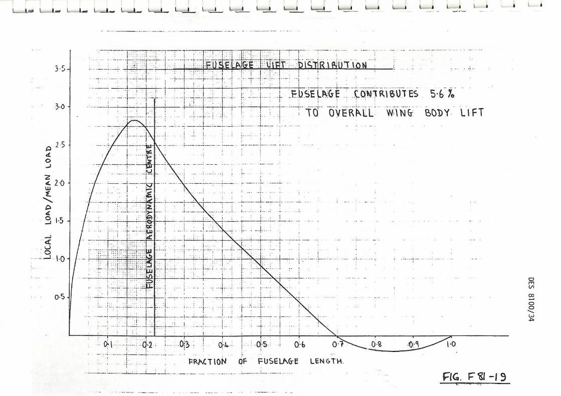
The wing spanwise load distribution due to incidence, flap, spoiler andtailplane load distribution due to both incidence and elevator deflection is given in Fig15-17.Whilst the corresponding information for the fin and rudder is to be found in Fig. 18. Fig39 shows a typical lift distribution along the fuselage. The shape of the distribution is dependent upon incidence and the diagram given is a meansfor initial loading calculations.
DES 8100/12
Chordwise load distributions vary substantially with Mach number and lift coefficient. The curves given should only be used for local design of the various components and not for overall balance calculations. Typical wing chordwise loading due to incidence is shown in Fig.2Dwhilst distributions due to flaps, control surface, are given in DES 8041. The chordwise loading on the tailplane and rudder may also be derived from DES 8041.
9. References
1. NASA CR 158950. Cargo logistics airlift systems study VOL.IV.
2. Article - Heavy lift aircraft studied by Air Force. Aviation Week and Space Technology. February 23rd 1981
1
1

DES 8100/13 TABLE 1
MASS BREAKDOWN
COMPONENT CIVIL MASS KG
% AUM MIL.MASS KG
% AUM
. Wings 42190 9.68 42190 9.68
Fuselage (including freight handling equipment)
40697 9.34 45527 10.45
, Tailplane 1950 0.45 1950 0.45
J Fin 1950 0.45 1950 0.45
Main Undercarriage 13152 3.02 16748 3.84
Nose Undercarriage 2320 0.52 2956 0.67
STRUCTURE 102259 23.46 111321 25.54
Engines - Dressed (+Fore Prot.) 20430 4.69 20430 4.69
Powerplant Structure (Pylons, Cowlings) 2683 0.61 2683 0.61
POWERPLANT
:0-
23113 5.30 23113 5.30
Fuel System 1044 0.24 1044 0.24
I/ Flying Control System
Hydraulics
2506
1911
0.57
0.44
2506
1911
0.57
0.44
T
Electrical System
Instrument and Avionics
1634
1453
0.37
0.33
1634
1453
0.37
0.33
De-Ice System 227 0.05 227 0.05
I Paint 363 0.08 363 0.08
Furnishings (Crew Compartment only) 1634 0.37 1634 0.37 1
Air Conditioning System 1998 0.44 1998 0.44
Auxiliary Power Unit 863 0.2 863 0.2
11 SYSTEMS AND EQUIPMENT 13633 3.13 13633 3.13
IBasic Operating Empty Mass 139005 31.89 148067 33.97
J
JJ
Crew (4) 363 0.08 363 0.08
As prepared for service mass 139368 31.97 148430 34.06
11 Payload (Both decks) 155696 33.73 146634 33.64
ii
Fuel at Max. Payload 140776 32.3 140776 32.3
ALL UP MASS. 435840 100.0 435840 100.0 -I

•
TA BI I
DES 8100/14
MOMENTS OF INERTIA - CIVIL VERSION
(Relative to wing 0.25 mean chord line)
CONFIGURATION MOMENT OF INERTIA 103 kg - re
PITCH ROLL YAW PRODUCT
As prepared for service 139368 kg
30709 29749 40358 1321
Increment due to 140776 kg fuel
3147 6133C 64123 -187
Increment due to 155696 kg payload
46865 574 46291 -675
TABLE 3
PROPOSED FLIGHT PATTERN DISTRIBUTION - CIVIL
Stage Length km
Mach No.
-
Average Altitude km
,
% of Total Flights
500 0.75 10.06 9.15
1000 0.75 10.06 7.63
1500 0.75 10.06 1.04
2000 0.75 10.06 2.5
2500 0.75 10.06 2.4
3000 0.75 10.06 2.08
3500 0.75 10.06 0.88
4000 0.75 10.06 0.9
4500 0.75 10.06 1.0
5000 0.75 10.67 2.77
5500 0.75 10.67 2.64
6000 0.75 10.67 39.76
6500 0.75 10.67 15.95
7000 0.75 10.67 1.04
7500 0.75 10.67 2.5
8000 0.75 10.67 3.84
8500 0.75 10.67 3.88 -J

4.306 TOTAL
ATA CHAPTER NO. DESCRIPTION
1
DELAY RATE
21
22
23
24
25
26
27
28
29
30
31
32
33
34
35
38
49
52-57
71-80
Air Conditioning
Auto. Flight
Communications
Elec. Power
Furnishings
Fire Protection
Flying Controls
Fuel System
Hyd. Power
Ice Protection
Instruments
Landing Gear
Lights
Navigation
Oxygen
Water/Waste
A.P.U.
Structures
Powerplant Systems
0.047
0.04
0.099
0.095
0.02
0.106
0.157
0.125
0.284
0.046
0.035
0.803
0.073
0.2
0.019
0.01
0.039
0.533
1.375
DES 8100/15
TABLE 4
DELAY RATE TARGETS FOR INDIVIDUAL SYSTEMS
(Civil Role)
Delay Rate = No. of delays > 15 min + cancellations
100 departures.

DES 8100/16
w114(1 &WAAL ilit110111}T

OIMENSIONS IN METRES SCALE 1:100
F It PROJECT WING Mel TAIL GEOMETRY
1/4
TO HOSE
11.0
73 27
10.9
70*/
FUSEL AGE
21
DATUM
2.4
_ 0 4
90
81/0018
S30
85 asJ
0.
FUSE
LAG
E DA
TUM
40 r""' L ! 9
2; 55 I
0
I I
SEALED SLATS 11411.CHLY1
1
L„,„,,iiis L „Ho.", L L L „La I I I s • L

I C_At. r.
L L L _ _s L_ _ L a L L. s —
TRAILING EDGE FLAPS MILITARY VERSION WING SLAT OUTBOARD OF INBOARD PYLON
PILITARY VERSION SEALED WING SLAT INBOARD OF INBOARD PYLON
25°
TAIL PLANE SECTION 10%. THICKNESS AT 37 5%. CHORO SYISIETRIC - SCALE UP TO 12% FCR FIN
0 0 0
1
611001. 8
S30
WING IF AEROFOIL SECTION RAE 9550 DRAWN NORMAL TO L E (SCALE UP FROM 12 2% tic FOR INBOARD SECTICNS) 40°
LANDING.,
F 81 PROJECT - AEROFOL
AM) CONTROL SECTIONS
_a_ L . l . 1 . I _
• - . 1: ,--->- --- --.0 - - -.:=______------ 1 , i t--- ,..-&---- 1 1-- ,•—r'
‘,_-L. ---------4— ---------- e —
N
SCORPION LIGHT TANKS WEIGH 78 KINNES_ EACH
SCAN BE AIR-DROPPED)
wESTLAN) * Mk HELICOPTERS WEIGH 3.7 TONNES EMPTY
EACH
/
UPPER FORWARD TROOP OEEX- 35 TROOPS
UPPER REAR TROOP DECK -150 TROOPS
5 TON TRUCK
CHEIFIAIN WI BATTLE TAWS WEIGH 52.3 TONES EACH (LOCATED NEAR FORE-AM-AFT (.6)
Ns L
OU00
LB
S30
95 M
11* siETLED uNE
f
RAMP EXTENSIONS
FWD
11\11 / / / / / / / / / 7— , Ty—T`---- NORMAL STATIC LK F 81 PROJECT
FUSELAGE ALTERATIONS FOR MILITARY VERSON
WHICH FOLD TO FORM PRESSURE BULKHEAD
F - 01-S
LEVEL SPr e11/4AVeLoPE
M ki=
MCSK1.1 LiftArr5
ecauivALEKr • 1•11• MEM,
too zoo 300
LEVEL sPEE3 M l SEC,
L3/0018 S30

PAY LOA gikt\S s.K1 V LOPE
-Fvf4E
EXTX,...t.bEh MitV.
4550McS I ,5A CONI7NtTici-31S
C_Cu1S4_ 0.75, 35ewit
(i5% ItEs tRvs)
a/0
01. 8
S30
F(4. Ft1-7

LioiL L_ I L 1 Ll LI • _ a
LOW _5P CuRVE SLOPE1C ry
-z 2 4 - I0 '4
'Nfott,a-Gi
F- SI —41-
cz/oot8 sal
. .1.
• -r
a. t vajr,
14.4. • ;( _ . •
• - -
• ••-••• •
• Vr t
: 410
•
I__ L_ L L
coeve st jtwe w-Tvl mAcH
. • - •
• . . • . t— i .
.
... .. -. - ,. : - . .. i -. . i . , i • • I • 1 1
I • • •
- i . • ' ' : - . 1 . • • '''' 7 - 1
i — . • : . L t . • -• . I • ' • _._ - - , t - :
; —7— .. : !
—7— 7 • r ,-..--.—r—t--:-- -- i.- " -,- _.-..-r•--. 7 - - 7 — 7- !-•-
: i,.... •. ._.. 1. ... .._ _ . i 1 . . . 1
_ '.. . - i . . 1
• . - • - : !
• ...-.'• ./-. • ...•
1 -
r •
1 L.
-'''
i
.
- '''
: •
1 —.4 ....—
—4- -- . ;
—6--1,-
..--- 4 • .. '.
— e ..., :4...-,. 'r.... L!
.
• .
— - ---i---:---- 5 • i • 1.- i - ... ..1
k75
(A
00 .'
. 1 I • -
, ! .
. . . I_ : ; : ;.. I' ' 1 • • 4
• . 151.Z.' - - ;
, • i • •• 't . • • - 1 •- - ' ' . . ! :
. • f - . ' 1. ' • . i .. : i
., 1
• • : •
•-
;
•
' ...— 1 , • 4: __t.....,_ f
.,, .• . • . . r . . . . . . . 1 . . . :
_r-L.
zli. . - • : • , •
FIG. Fcal — 5.
0 Roca-
.2 -3 .4 -5 .7 .8- tot.
SPA-N iNitce FoSt110t....1 ft. 7-= 42- "1/..b vco-r --r p.
SA -10
V*C16 T ION or 40 1PS G A C E_NrreE A-ceoss s f•ik\
SZ/001.8 S10

Li)of
YAK t A Ttot.S oF -TAIL PLANE A. Ee0 c er.st-e& A cFosS S fANS
ft FTI - 1 SPMQ v.it S6 - i
M= O
-5 -4 • 4 1.0
W/0018 S3
0

U. fl
LZ/00L8 S30
H ..1414T • 7
FUSEidreqe tien.)64
R4. F 21 -17
0:3
1 • 0
LQ.) %/An o TiO o FiKs A ER-0. C A cru:SS S PAt
0 twG v Es --
-z -s
MACW 1.supeits •

tid l a v 1L-1 1-1 1_1 L I
Fer L 1,14its4 7 - - -
- 7 -
-
7 .3
'I •
m
c,
z 4- rAn 'Bitnti%1 4*--41g€ES . 1:
- t- -
i• • .... • I
•
Fici.1151 — 14
L1161140
it:.) 11:5

1 ;
• d---• -
•
;. _1.. I
1
I f -
1-- •.:
.t •77-'"
DES 8100/30 '. 1 :Fr-, i. 1 , .- • F - ?-• 1-- . ;•--i . J . i • ; - i •
- • .1+ 1
- I 4-
• ! 1 . • - 'I IL
',_
r ; ,1: I..- I • • ;
i
...i . ' i • 1 ; • 1-!-1,, 1 1 I • I
' . • '. 1
i'• I 1 .! i :. .1'" 1. : 1 • Pl "! l• I . -. .
--4 ,
...._........[.. ;.. ,....1...., .........______ _._ . ._., :_.... try' {•- .1,,_ •
I ; ' i ' 7 I ' ! •L i i::. „. . ,
• . , . . .I ..
ir+ 1 ' H-1-, 1'. •' :... . 12 ' ' --i--- - • • I
. . I . ' I i
' • - . ' • 1 / i 1
I 1
' - ' . . : ' i • i '. .i ! •
: 1 i
•
if
I
•4 -
1 + :. ;
. .
r • : . 1 ': •-• I
, .
1. ,
I ; -• --,,i-••- ••• 1/1 •
•
i.
. 1.
I._ ..... ... ..:
' • 1.- •:-.•J;---I..--1 ..i: ' .0
:. .
, , i•
i . i -
I
' . :-' .1 H .
. ' ,
I ..-1-" i. • ,-._;.. :. . I
: . . • i
• I t 1. .11...
7r . :-. 71'. 7.4 71 “4 ;.:. • n
k ' . I . •: ' . 7 f . - -. --:.
i • - . . 1 . .
t r .. .I i .'
.- :. ..., ..: _...,....4-. --; -••• '71-'-'—'1' - ---•.—r -- s' _:. __4
-• •
*1-1-
• r
.11: •;;..
1 -. •4
I.
• • • .1•• • i 1
1_, • -;
. I
1:'
i•
; • ir.
--,-• I
- •
• • 1 •
;_

3_
N L__i 11_11 L. _1 L 1 1 _11 IL 1 . I _ _1 IL-1 IL i a ••••••• •••••••-•-r •.--••••
_- ,7sfort0-S:.. scli ik-rS -
- - • - - - r - .
• - • . - r . 777r77.. - •
.
.. • .
013e0b-
•
r - • : • • ;- - •
• I. ; • - 1- - •
• • • -
• , .• •
• -
7' (7
. r
. • a • - • : , .
- . :
-1 - F
, .; • . ; " .
1 1
1 : • t
1 1 -
FIZACTiom I •.. r: -mei
: . .
. . . . , .
-fr
• . r •
_: • L_ - . I •
FIG, FS?
-1 '
g-L
S Pe MARS. -
_ .
-
--1 . ; au-rlifioAgtii • }_WS-.. •

' sTiltuytie isTe. r-
-$17A1\ FkG r
PRA Cr it#4

Ri\c'rlOt4 OF FUSEU\G-E LENGTH
F -I 9
tE/o
ote
S]G
• t • 1-- •
. . !
-r
7rirtM)1•i6 A 3-5-
L SD pk.(yr 0it/IRMO ES S.6 7
OVRiklil. WIN6 BODY LIFT 3.0 -
L
•
• • '17" 7 -I- L
.....
• •
4
0.4-1 ta.6
•!.
7
. :
" 7.;"7•!'
0 21
Mai
DTW
ER
-tilliffailliffillffili111111111111111111111111111111M111111 IffiliffilliligliiiiiiiiiR1111111111110piptipiliglilappiliMMillipilffig M II ISIEMEMINIMIIIIIIIIIIMINIMICAthlir ....‘ 4,, 1118EMMIIIIIIIiiiihil111011111111111011111linilingliiiiiiiidifilllilli INNIMMII1111111111111111111E1111 11111111111111MARIIIMMIIIIIIIIIMPlii PinifiliiillifililliiiliiiiiiP.T.MMIN IF iiiiiiiiiiiiiinin milli
atallinglliflal• iiiimiimplmdlinillWilliir :.• iiiiiiiiiiiiligMailliallffitiri'i •'''' iiiiiirtimii 1: op
LH 111111111111111111?"11111 11 •••1" --PNI::: Mr allilligill -1 -11'1 id r"i' i l'Ill'IPINPilliitilliiiiindildEniniiie::Himimi!gdpiiii.:: ::424,11111:g.imi
rill In i um linuilliffirallifiiiiiiMiliiiiiMMIIIIIIMInnniiiiiiMilii 1:::'• kniiiiiiIiiiiiimani.. tiiiiil iiiiiiir iiiiii • • • x-sirnarr- 3:i .... -q:=;.. ....... gpiiiiartiiir.::iithri-Fmnr.::: 1 Ham piqiii c Imp
11-iziirdi ii iliiiiiiiiiNINMENEITE1111111111iltriiiiiiipielligniiiiiiiiiii 111:E122 d:11111,41112[1:i hmi /I" 'Ili N ifillni11201,1' iiiiiiiiiiiiiiiiiiiiiiiiiiiiiiiiiiiiiiiiiiiiiiiiiiiiiiiiii LAMM li 111111111Villigirli1111161piiiiiiPlihilltillitilltillaitaillitlinorlkwarilitioriliimer lit 11WHINIIMIiiiiiiiiiiiiiiliMililliNiffillimmannn allild Aid
mil 4iii I 11111011111111111NENhinliiiiiMilliMplinit-J irtiffil RZtrilit 101:511110,0111,iiiiiiiipi.111461% iniiiiNi11110111111Milig111111111011111fl All 11 r Mit iiiihilp
liniiiiiiRIP iliiiilleilikk, Ii, 1111111111111110114111111111111MIMEILMJIMUMUSIldmilihiallniiiillihNildllih, Iffilitillnw mmimilipiri
1111111. 1111111111011111110111111fflfiliONONEfiniiimilifingliningliiiiMINNINIIIINIMMIL IlLEHMIT ME'
.:t I 1 , 4
DE 110111111111111111111111111111MIIIMMLIIIININIMMEnt."21"ntimilliMmiliiiiiiiirilliol gillnillEJIIA ti. i ii .1:: i :.. .... .: .:. 4:::_i .0=1 101310 111111111MINHIMIIIHNOENININIIDEMINKINONiiiiidiniiiithillira110110igik lipkilin miminairtx - ENE 51111111DMINIONIMENIMEMITilinilliiiiiiiiiiilliiiiiiiiiiiirdihMilElEniii:• 61i11:411 IiiiiiiiiiMillillei ::: • • - ill . I. Ali 1111111NWIEN11111E111111111.111110101011111111 II: 1::. : JihiAlilii: UM IiitileilintIL- ni •Eir:::::• :::•i: ::: 4.1 1 : i •
1111111111111111111110110 1 INEMINIIIIIMMIHRIMIM 1...LORENNI;Elliiiiii 1 iillillibinliiiligliiitil lihiliiiiil IiihMalli h u4h1111111Mil iffliEnilliiihrlidffill111111111 MinnEkilliiiiiiiiiiIiiiiitilliiiiiliMini '" hitilkli1111•11111111111110111110 MEE 110101011111111111=1111111MIHMHIMMEINIIIIMMOIMillitiptiAniiiii.iihniophoolgq jisiligliKiliiiipiimihnlipldniiii .1 • • • • • ••• ino,:•-••:::•0 : •-::::•::•::ET 1 „I. •::0:ini 11.,:1-ii.dhl mailu• il' -'-
.
EMU MEM
MIPMEMMEMINEIIIMMIIIIIIIINNIUMWahaffilliOillidilliiktglingifilidlYilit ilitoilini fogipoulnkal
NormmmoiliNiraluviiiillimiliiiiiiiip mtimilimmilifililifilikeiviiiiiiiiimgiamomaiir.iiiiiii tihimilingiut Eiii:iriiil!if I I 1 II '•i :::111ei• •t; •E.:Re PIE•131timarn=nET::::iiii-iii iiiii ------simamiiint9Fgepinii: 3 sEi:tm-skiiEr: • - . :::-.1::-.:zi: MENEM
EHROMMEMININnhiniiihiM fliiiiiiihkilniEllidlielliEtusuulipsmidiguisiiiiiplEmiq:10010_1 tiiii11111=fri .41.hicIintih.
ett3.1 I'. 1111111111 1111911aNNINIENINNIIMMUNIMERViliniiiilniltgunipliiimiliiiiiimigqiiiiiligi th 1111111041I01 li ' MENEIMEININ .... 1 JIM PIPPVIIIMIHMErmodll ' gm ilikiPP:g.. F'• - •••1,::,-,,7•411Fihnirg:imi,F4INiii :illellipliiin !di .E •: , _d_____. ii...-4-:::-::1:::::0-1-1 :=9:111:.:a...... mizi:-.4::!.1 ::.. LI. / ..:.._ :... Iffil IMEllith011alidil iiilaNIMEINIL . REEMEM111119:01 ....... i iiiiiiiiiiiii:::::iiiiiiiiiiiiiMagli iiipliiiiiilhlaiiiiiiiroiniE 11M121111111111Elinnunilliiiiiiiiiihiliiiiilhal IIIMINNIIIIIIIL: ... Aligiiiiiiiiiiiiiniiiiiiiiiiiiiiiiiiiiiilik 'PkiNIMiliiiiiinglill
3. ill ' 1111111111141111111111101 iliiiiNiliiiiiimilIMEIMMIREIMinlilliiiiiipplEiliiiiipiniiiiRMINIMIRMilf• illMEM 101111111111111111 MI IlilligliElliiilliniiiiNENIERNAISMilitniiiiiimit.""LblitmilmmiligimpHipillitiippm :i
Iti
mum Milli 111E1111111111111111111111111=1111h111112M1111111MINIME1111111111higliiiiiiiiiiiiiiiiiiiiiiiiiliiiiiilliiiiiilliiNINIMENEliiiIME EMI 11111111111111111111IIIMM1111111111111111111111111111111111111ildweinmignin!kmanniimilitimilniumkiEiliihnalialEnipiiiiiiiiii
EgmEN Iffimhinging ramilinmillimproginimpaiwagliMili;;;:;:phEinligiiiikmidgmhibmilliiiiiiiiiii 1? moniumannulinmainu BEREIRORNiunalimillimmlimilmlugirgii!saimilffliPigNiifirtaiiitiligiiiPffiliiliiiiirghigi MEE =1' rt5011 uM111-.-n7ofilimoTir "reiVatimilialigh•Ziliiimiliimorquillikimilimuur IN MEIHNEHLO 1 1 niiiiiiii i ilinffiliNIME idiNgiliniglififfialliiiiittliliN illiiiiiiiiiMiglifit 1111111111111111111111110
us* L pue # 'Lusts LOSS 'I'll rico LidwID I 1 14 ■

9E/0
01. 8
sa
i
. :
44 Cm.c)
16V+ 1A-g3 363
I-1 232o
1k SS7 (23 I
11SS7 462as
28-1) 2ooG
e . .............. !...
..7. : ... .... .... . . • • • ; • • r,
..... .
" " .... •• - 4 ...... .... .. •
.... 7177 ......... 7: : . ..... • : : . • . ...
. ... . . .... • . ..
...
.. .
1.• .... .... ^ .... .......
. .... .........
...
. ..... : . ..„ ........ : ........ ............... •
.... . ........ 1
..... ..... .......
...... ..... ........ • • •
.. I
...
...
1 ........
TOTAL-. 1Z91GB 4q. • 7:.. 7_7:71 „,
...... ..... ;-, •- :; ... ......
: . . : .. ... ....... . • .. .
......... . ..... .......
. . : . :
... ..... 1
7 ........... .. . . .... . .
...
.......
.........
• :••
-r ...
. ..
. ..
.... .. : :
.... : ...
...
....
.....
............ .........
. . ...... . ........... . . ....... F81 -Z1 • • .... ........
......

21 os5' 522 4-27- -
57 7r7 vo
s-re Qr.:31*k vuEL s.yS.
co 121..5 - .1-1 CS
w .3)1s-r-O. mu-5 oKS
231 1 S 4E011 Ptiva6e, VLIWIT
4WD
2 y- FNALceftitizts I S57
"TerrAL /MN G 34 67t
PoWeZ RAM
ARAL, FLIst.3G co at. S.x c -tcE 5/STEMS
SIELIC.TUR E
3:14STAINCE-
0
F16. F SI -22.

6.1011., 6..ma 65111 60J
2 4-
2:1t5Tht-aC. 0 ig OF
FCC. i -23
8c/oom S]C
1
• ••••••=-..
.1.
0 4- 5 7 S
4TAmCE AnI3o1 Fi)5 et44 E VOA (114%)
R4 , FV-
6C/0018 530

ic
1410
120
5 7 AD
10.1 11..1
FRS t Ca t_rr Lo1a uNI 4 tf+fC-1?)A-11.01
1
EMyCLOPC AU Ow ItriSt€
Re IDOL PA-11$4.1)
C041)eifQ er-Fec oc FeeL St + Pr- ) •
Co
IP zp 30 40 Sic) 60 70 ItO oc. F ME•kt AT-f-615%./K\A-M -Ci-koer
loo
FIG -25
m ,pmomiiiiii. ii ii !! 1 prilivolimmENEEENiimilimiumiyi RI : .g
MEW Hill 111111111111111011111111. - P. Annie • trigigitialn ME OMNI 11111111101111111 111111MINWHIHM111 1111Ho HiniommiiiinaulaysilliiiiiiiiiMiritliiiiirilli.. TiiiiiiIIIIIIIIIIMIlin MIN 111 1111111111111111111111111011111011111 1111111111111111 UMW 11111111111i11111111111U HO 111111111111139111k 1 EMERIO11111111 11111111111111111111111111111111111111110411111111111111M 1111111111-1 ER111111111111111 1 11111 11111 1111111111111111M11111u T f!I 1.1
651r*M""41171rla "111 1111111M1 WillEll"liffil„:11111111'11111101111111111111111111 LI 11111111111111illin Efig. :1111111M2 1111111 MO Muffin i
ElialliMMELIi"1 1. IMMIL ill.1 1: 1":inifi"R11111111121211111111 111111111111Mr V"11101011ffi mompumami"lt 1 Erni nil Ns= wijammithighiNimimill , li ..., 0 ,
• iili ill; pit! fill .1111M IMIiii
MPanilniluil.11111thilif ,!: .1 I ,I 1 1111 lid= .[NEHENHINIEMMEHOZNEelot- R ;iii iiMel 19 1 u gTilOtti Fri 11..1..iri ullIVIIr Ira ti-7-.4 ITIT iinill111110111111101111i. i .ti'i 41111MENII
offilliummimm lig In ii BEM lif 11111 1 0 i.i tl' -r•ilffi , ii lin !ili , i!! 111111111111111111111 MOM
II IDIMEI
ErariangREE Millii1111111111 11111111111U
RNEREEijimll 1111111111111111111111222111 HINIMBIO
NH MiNilliliiilliMIMMEINEEMMUMMINIM dliiiiiiiiMili 11111 11111
IIIIREMEMMEMMEREMikliddlifilliihr Iffipill11111 10 Hill 11111MINIMMINEE
llifiliiilli1111111111110 PEE; Mil 111111E1111 11111
111E1111HEN llinfiffilifflEM
1111111111EliMiligifili 111111111111111 MOMtEl
Utim-iffm mi 1011111=111111M111 111 11111ffinillill M.. NM 11111111111111211 111 111111111ffifillifill IWEEE1 El' 111111111111110 11
lairrimilli um maiir01 IIOM 11115111111111111
IMO 111ORMIMP NMI=
elfag....z5MWNEto
MEE EtElliffitaliall II THISilliiini dill IIIMIP111111111111111101 EMI 11111111111LIffillffl mmoommili111111
E1E Mil IN OM El 111111111111 MiliELIIMEME1 i• 11111111111111111111011 11111111111L will EfillillitiM1111111m—MINIEWININ 111M W11111111111111
ER 011111111111111111111/1111111131111 101111111111111 1011111111111111
E-Numigiumwmountianth El Ili illi110111Effi IIIMINilliiin OM ININININIMINE EIMMIIIIIIIII NM 1111111111111111111 Mli
0111111 111E1 OM RIM Linn'
if
ETSIIIMMOMEEEM1111111 11111111111111 1111111111ZMIHM
tiMMIEILLCIZEidifM H
NM HO 1 41 OIN111H IN MOM 1111110.1111111 HI 11
111111 11111111111111111111 ill 1
MA Iffi 1111111111 11111111111111 • • • •
ffifillIMMIUME1111 fi