Embed Size (px)
Citation preview

PAPER www.rsc.org/loc | Lab on a Chip
A lab-on-a-chip for detection of nerve agent sarin in blood
Hsih Yin Tan,a Weng Keong Loke,a Yong Teng Tana and Nam-Trung Nguyen*b
Received 10th January 2008, Accepted 13th March 2008First published as an Advance Article on the web 16th April 2008DOI: 10.1039/b800438b
Sarin (C4H10FO2P,O-isopropyl methylphosphonofluoridate) is a colourless, odourless and highlytoxic phosphonate that acts as a cholinesterase inhibitor and disrupts neuromusculartransmission. Sarin and related phosphonates are chemical warfare agents, and there is apossibility of their application in a military or terrorist attack. This paper reports a lab-on-a-chipdevice for detecting a trace amount of sarin in a small volume of blood. The device should allowearly detection of sarin exposure during medical triage to differentiate between those requiringmedical treatment from mass psychogenic illness cases. The device is based on continuous-flowmicrofluidics with sequential stages for lysis of whole blood, regeneration of free nerve agent fromits complex with blood cholinesterase, protein precipitation, filtration, enzyme-assisted reactionand optical detection. Whole blood was first mixed with a nerve gas regeneration agent, followedby a protein precipitation step. Subsequently, the lysed product was filtered on the chip in twosteps to remove particulates and fluoride ions. The filtered blood sample was then tested for tracelevels of regenerated sarin using immobilised cholinesterase on the chip. Activity of immobilisedcholinesterase was monitored by the enzyme-assisted reaction of a substrate and reaction of theend-product with a chromophore. Resultant changes in chromophore-induced absorbance wererecorded on the chip using a Z-shaped optical window. Loss of enzyme activity obtained prior andafter passage of the treated blood sample, as shown by a decrease in recorded absorbance values,indicates the presence of either free or regenerated sarin in the blood sample. The device wasfabricated in PMMA (polymethylmethacrylate) using CO2-laser micromachining. This paperreports the testing results of the different stages, as well as the whole device with all stages in therequired assay sequence. The results demonstrate the potential use of a field-deployable hand-helddevice for point-of-care triage of suspected nerve agent casualties.
Introduction
In recent years, the growing concern of terrorist attacks hasresulted in a demand for point-of-care diagnostic devicesthat allow fast and effective triage of casualties exposed tochemical warfare agents from the “worried-well” masses. Sarin(C4H10FO2P,O-isopropyl methylphosphonofluoridate) is a phos-phonate that is highly toxic to humans because it acts as anacetylcholinesterase (AChE) inhibitor to disrupt neuromusculartransmission. Sarin belongs to the G-type nerve agents and iscolourless and odourless. The lethal concentration-time doseof sarin for 50% of exposed individuals (humans) is 75 to100 mg min−1 m−3.1 Sarin and related phosphonates are chemicalwarfare agents and there is a possibility of their application in amilitary or terrorist attack.2 Thus, there is a need for its detectionin the prevention of an attack and for early treatment afterexposure. Fluorescence is frequently used for enzyme activitydetection in the presence of a nerve agent. The enzyme canbe immobilised on packed microbeads to increase the contactsurface area.3 Zhang and Swager developed fluorescence-basedfunctional group specific ratiometric chemosensors.4 Simonian
aDSO National Laboratories, 20 Science Park Drive, Singapore 118230bSchool of Mechanical and Aerospace Engineering, NanyangTechnological University, 50 Nanyang Avenue, Singapore 639798.E-mail: [email protected]
et al. developed a detection scheme based on a competitiveinhibitor, whose change in fluorescence is generated by goldnanoparticles attached to the enzyme.5 Viveros et al. used anoptical wave guide with immobilised enzyme to detect the changein fluorescence.6 Bencic-Nagale et al. used nerve-agent-reactivemicrobead probes with fluorescence as the detector.7 All of thesereported approaches did not use a microfluidic platform forsample analysis, and none of the papers reported above workedwith whole blood as the sample.
Microfluidic technologies have been shown to be a promisingapproach for the integration of protocols for detection of nerveagents. Nerve agents are detected based on inhibition and non-inhibition concepts. In the first approach, the nerve agent worksas an inhibitor of an enzyme such as AChE. The enzymecontrols a hydrolysis reaction whose product can be detectedelectrochemically or optically. Hadd et al. reported a micro-fabricated device for detecting AChE inhibitors such as nerveagents.8 The inhibitor reduces the activity of the enzyme, whichin turn affects the hydrolysis of the substrate leading to a decreasein fluorescence signals. In the non-inhibition bioassay, the nerveagents are separated by capillary electrophoresis and detectedelectrochemically and optically. Wang et al. used a microchipfor capillary electrophoresis separation of organophosphatenerve agents,9 in which amperometric detection was employed.Pumera gave a detailed review on the detection of nerve agentsusing capillary electrophoresis.1
This journal is © The Royal Society of Chemistry 2008 Lab Chip, 2008, 8, 885–891 | 885
Publ
ishe
d on
16
Apr
il 20
08. D
ownl
oade
d by
Sta
te U
nive
rsity
of
New
Yor
k at
Sto
ny B
rook
on
24/1
0/20
14 2
1:26
:39.
View Article Online / Journal Homepage / Table of Contents for this issue
Recently, lab-on-a-chip (LOC) for diagnostics of blood sam-ples has been an active research topic.10 The challenge ofsuch devices is the integration of the preparation and theanalysis of a sample. Sample preparation usually starts withthe whole blood. Before entering the analysis stage, the sampleshould pass through separators, cell lysis reactors, microfilters,and concentrators. Since only some components of the wholeblood are of interest for the later analysis, it is necessary toseparate these components from the rest. Cell separation isusually the first step in sample preparation. The next step isbreaking down the cell membrane in a cell lysis reactor. Thesample is subsequently filtered to reject particulates and othercomponents that may affect the later analysis. Before enteringthe analysis stage, the analyte can be preconcentrated to improvedetectability. Readers may refer to a recent review by Toner andIrimia on preparation of blood samples.10 Liu et al.11 reporteda LOC for sample preparation, polymerase chain reactionamplification, and DNA microarray detection. The polymericLOC device for blood typing reported by Kim et al.12 uses wholeblood as the input sample and consists of sequential stages suchas micromixer, microreactor and microfilter. There were veryfew reports on complete integration of all processes from samplepreparation to detection on a single LOC device.
Previously, a prototyping technology for LOC devices madeof PMMA was established by our research group. LOC devicesfor polymerase chain reaction of deoxyribonucleic acids13 andfor detection of sarin in water samples14 were developed andtested. In this paper, we report the design, fabrication and testof a polymeric LOC for detection of sarin in blood samples.The following sections report the detailed implementation ofthe detection approach based on absorption measurements ofthe inhibition reaction. The design and fabrication of differentcomponents of the LOC are also discussed.
Detection approach of nerve agent, sarin
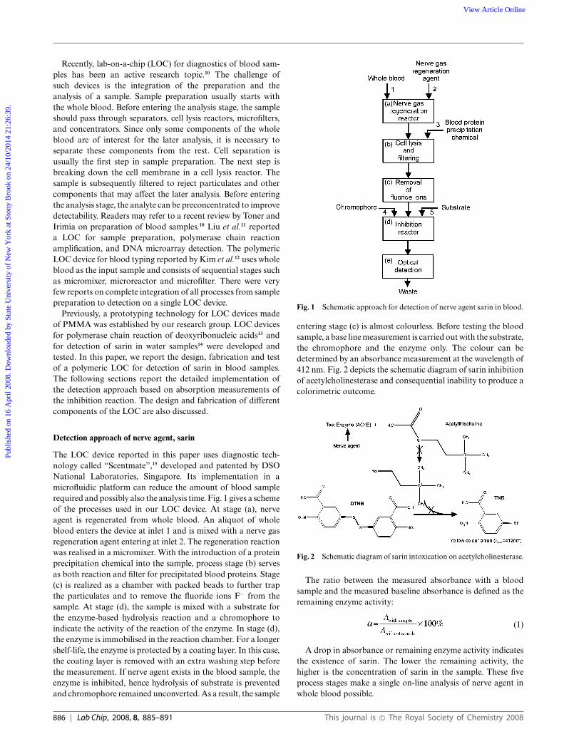
The LOC device reported in this paper uses diagnostic tech-nology called “Scentmate”,15 developed and patented by DSONational Laboratories, Singapore. Its implementation in amicrofluidic platform can reduce the amount of blood samplerequired and possibly also the analysis time. Fig. 1 gives a schemeof the processes used in our LOC device. At stage (a), nerveagent is regenerated from whole blood. An aliquot of wholeblood enters the device at inlet 1 and is mixed with a nerve gasregeneration agent entering at inlet 2. The regeneration reactionwas realised in a micromixer. With the introduction of a proteinprecipitation chemical into the sample, process stage (b) servesas both reaction and filter for precipitated blood proteins. Stage(c) is realized as a chamber with packed beads to further trapthe particulates and to remove the fluoride ions F− from thesample. At stage (d), the sample is mixed with a substrate forthe enzyme-based hydrolysis reaction and a chromophore toindicate the activity of the reaction of the enzyme. In stage (d),the enzyme is immobilised in the reaction chamber. For a longershelf-life, the enzyme is protected by a coating layer. In this case,the coating layer is removed with an extra washing step beforethe measurement. If nerve agent exists in the blood sample, theenzyme is inhibited, hence hydrolysis of substrate is preventedand chromophore remained unconverted. As a result, the sample
Fig. 1 Schematic approach for detection of nerve agent sarin in blood.
entering stage (e) is almost colourless. Before testing the bloodsample, a base line measurement is carried out with the substrate,the chromophore and the enzyme only. The colour can bedetermined by an absorbance measurement at the wavelength of412 nm. Fig. 2 depicts the schematic diagram of sarin inhibitionof acetylcholinesterase and consequential inability to produce acolorimetric outcome.
Fig. 2 Schematic diagram of sarin intoxication on acetylcholinesterase.
The ratio between the measured absorbance with a bloodsample and the measured baseline absorbance is defined as theremaining enzyme activity:
(1)
A drop in absorbance or remaining enzyme activity indicatesthe existence of sarin. The lower the remaining activity, thehigher is the concentration of sarin in the sample. These fiveprocess stages make a single on-line analysis of nerve agent inwhole blood possible.
886 | Lab Chip, 2008, 8, 885–891 This journal is © The Royal Society of Chemistry 2008
Publ
ishe
d on
16
Apr
il 20
08. D
ownl
oade
d by
Sta
te U
nive
rsity
of
New
Yor
k at
Sto
ny B
rook
on
24/1
0/20
14 2
1:26
:39.
View Article Online

Experimental
Samples and reagents
The nerve agent sarin (GB) used in our studies was synthesizedin-house within DSO National Laboratories. Whole blood wasdrawn from an adult male and spiked with sarin and used asthe sample for our experiments. The synthesized sarin was firstdiluted using autoclaved water. Next, the solution was pipettedinto a blood sample to obtain the required concentration for theexperiments. Extra precautions had to be taken while handlingsarin during spiking and disposal of the waste. All experimentsinvolving sarin were conducted within a negative suction fumehood in DSO National Laboratories.
Potassium fluoride (KF) works as the nerve gas regenerationchemical, which reacts with the spiked blood and regeneratessarin. A saturated salt solution (SAS) works as the blood proteinprecipitation chemical.
Phosphate buffers (PB) of pH 8.0 and pH 7.2 were pre-pared by mixing Na2HPO4, NaH2PO4 and autoclaved water.The chromophore DTNB (5,5′-dithio-bis-2-nitrobenzoic acid)(Sigma, USA) solution was prepared by dissolving DTNB in0.1 M PB. The enzyme AChE from Electrophorus electricuswas purchased from Fluka (Switzerland). The substrate ASChI(acetylthiocholine iodide) (Sigma–Aldrich, USA) was preparedby dissolving ASChI into 0.1 M PB. Bovine serum albumin(BSA) and glutaraldehyde (GA) were purchased from SigmaChem Co (St. Louis, MO, USA). Both were used in cross-linkingsolution for the immobilised enzyme procedure. Trehalose(C12H22O11.2H2O) was purchased from Fluka (UK). Gelatine(Type B from bovine skin) was purchased from Sigma ChemCo (St. Louis, MO, USA). Trehalose (10% wt) and gelatine(0.1% wt) were mixed with sodium azide (0.02 wt %) (Fluka,Switzerland) to form a solution (GST solution) which was usedto protect the immobilised enzyme on the glass piece, allowingstorage of the immobilised enzyme at room temperature. Thesurfactant 50% Tween 20 (Polysorbate 20, 1.05–1.07 kg l−1)and approx. 50% lauric acid were purchased from DUCHEFA(Haarlem, Netherlands). These two reagents were used forpreparing the wash buffer that removes the protecting GST layerabove the immobilised enzyme.
Chromic acid was prepared by dissolving 5 g of potassiumdichromate (Alfa Aesar, USA) in 5 ml of autoclaved water beforeadding 100 ml of concentrated sulfuric acid (Merck, Darmstadt,Germany).
Design and fabrication of the lab-on-a-chip device
The LOC device is implemented on a 79 mm × 37.5 mm chip.Fig. 3 shows the overall design with the five stages from (a)to (e). The reactor for nerve gas regeneration is designed asa micromixer based on chaotic advection with herring-bonestructures. The channel width and depth are 2 mm and 0.4 mm,respectively. The total length of the mixing channel is 100 mm.The herring-bone structures are designed as ridges with a widthof 0.5 mm and a height of 0.2 mm, Fig. 3(a). Unlike thetraditional design16 with two secondary flows and alternatewidth changes, our new design reverses the direction of thesecondary flow in each period to improve the folding effecton each half of the channel. Since this paper focuses on the
Fig. 3 Design of the lab-on-a-chip for detection of nerve agent in blood:(a) nerve gas regeneration reactor; (b) cell lysis and filtering; (c) removalof fluoride ions; (d) inhibition reactor; (e) optical detection.
whole chip design, details of the effectiveness of this micromixerwill be investigated and reported in the future. Experimentalresults of the micromixers are reported in the subsequentsections. The reactor for precipitation of blood proteins isdesigned as a mixing channel with rectangular pillars for filteringthe particulates resulting from the blood protein precipitationprocess. The rectangular pillars measure 0.2 mm × 0.5 mmand are positioned in an array as depicted in Fig. 3(b). Thefilter chamber is designed as a chamber with packed filtrationbeads. The chamber is 15 mm long, 7 mm wide and 0.6 mmhigh. The inlet and outlet of the chamber are designed withsmaller microchannels to prevent the microbeads escaping fromthe channel, Fig. 3(c). Before the inlets 4 and 5 for the substrateand the chromophore, the width of the channel is narrowedto prevent backflow while introducing these chemicals into theinhibition reactor. The inhibition reactor contains a glass piececoated with immobilised enzyme and a protective coating. Thereaction chamber measures in length, width and depth, 15 mm,7 mm and 0.6 mm, respectively. The reaction chamber is locatedon the other side of the main device layer, with herring-bonepatterns to improve the transport of reagents to the glass surfacewith immobilised enzyme, Fig. 3(d). The reaction products enterthe detection path which is 4 mm long and 0.6 mm wide. Grovesare machined into the chip for aligning optical fibres.
The device was fabricated in polymethylmethacrylate(PMMA) using laser micromachining. The device was firstdesigned using CorelDraw (Corel Co., Canada). A commercialCO2 laser system (Universal M-300 Laser Platform, UniversalLaser Systems Inc., Arizona, USA) engraved the designedstructures on the PMMA substrate. The CO2 laser has awavelength of 10.6 lm and a maximum power of 25 W. Themaximum speed of the laser beam is 640 mm s−1. The differentchannel heights can be adjusted by the corresponding laserpower and scanning speed.
The device depicted in Fig. 3 was implemented in three basicPMMA layers. The main layer contains on one side, the channelstructures, the herring-bone patterns, the rectangular pillars andthe guides for the optical fibres. The herring-bone structures inthe inhibition reactor as shown in Fig. 3(d) are machined on the
This journal is © The Royal Society of Chemistry 2008 Lab Chip, 2008, 8, 885–891 | 887
Publ
ishe
d on
16
Apr
il 20
08. D
ownl
oade
d by
Sta
te U
nive
rsity
of
New
Yor
k at
Sto
ny B
rook
on
24/1
0/20
14 2
1:26
:39.
View Article Online

other side of the main layer. The access holes and the openingfor packing the filtration beads as depicted in Fig. 3(c) and 3(f)were machined in the cover layer. The bottom layer holds theglass piece for immobilised enzyme. The three PMMA layerswere bonded using the low-pressure, high-temperature thermalbonding process previously developed by our group.17 Under lowbonding pressure, the PMMA stack was first heated to 160 ◦Cin 10 min, and then kept at 160 ◦C for 30 min. Next, the bondedstack was cooled down to 80 ◦C in 20 min and annealed at thistemperature for another 30 min to relieve the stress. Finally, thebonded device was cooled to room temperature and removedfrom the hot plates.
After bonding the PMMA layers, filtration beads (Merck,Darmstadt, Germany) with diameters ranging from 63 lmto 200 lm were packed into the filter chamber (Fig. 3(c))through the opening in the cover layer. The filter chamberwas subsequently sealed by an adhesive (Araldite, HuntsmanAdvanced Materials, Utah, USA) with a PMMA sheet, Fig. 3(f).
The enzyme was immobilised on a small glass piece. Glasscover-slips (Fisher Scientific, Pittsburg, PA, USA) thickness0.1 mm were cut into pieces measuring 15 mm × 7 mm. Theglass piece was cleaned using chromic acid and rinsed in ethanoland dried in an oven at 100 ◦C. The glass piece was subsequentlycoated with APES (3-aminopropyl)triethoxysilane (Sigma–Aldrich, USA), a chemical used for cross-linking AChE. Beforethe thermal bonding process described above, the glass piecewas positioned using an adhesive on the bottom PMMA layer.After the thermal bonding process, cross-linked enzyme solution(10 units ml−1 AChE, 2.38 lg ml−1 BSA, 0.119% wt/vol GA)was pumped into the inhibition chamber. The whole device waskept at 4 ◦C for 12 h. Subsequently, the enzyme solution waswashed by pumping the washing buffer (1 part 50% Tween 20and 1000 parts 0.1 M PB pH 7.2) into the inhibition chamber.Next, the GST solution (10% wt/vol trehalose, 0.1% wt/volgelatine and 0.02% wt/vol sodium azide) was pumped into thereaction chamber. The LOC device was then kept at 4 ◦C for 4 h.After 4 h incubation, the GST solution was pumped out from theinhibition chamber. The LOC device was lyophilised at −40 ◦Covernight and subsequently placed in a vacuum desiccator for2 h. This step ensures the long-term storage of the device withimmobilised enzyme.
After the immobilisation of the enzyme on the APES–coatedglass piece and it was protected with a GST layer, the opticalfibres were inserted and fixed with adhesive, Fig. 3(e). For thispurpose, we used single-mode optical fibres (AFS105/125Y,Thorslab Inc., Newton, NJ, USA) with a core diameter of105 lm, a clad diameter of 125 lm, and a numerical aperture of0.22. The buffer layer was removed before the fibres were insertedinto the groves machined previously by the CO2 laser. Thecompleted device without the optical fibres is shown in Fig. 4.
Detection method
The absorbance measurement using the two optical fibresdepicted in Fig. 3(e) was carried out with a portable fibreoptic spectrometer USB2000 and its corresponding softwareSpectraSuite (Ocean Optics, Florida, USA). One optical fibreis connected to the light source (wave length 405–680 nm)purchased from Photonitech, Singapore. The other optical
Fig. 4 The fabricated LOC device.
fibre is connected to the optical input of the spectrometer.The absorbance signal is acquired, displayed and stored asnumerical data. After recording the base-line absorbance and theabsorbance of the reaction product with the blood sample, theremaining enzyme activity was calculated according to eqn (1).
Results
Test of the micromixer
In the following experiments, the samples and chemicals weredelivered into the LOC device using a programmable syringepump (CMA 100 microinjection pump, Stockholm, Sweden).
The micromixer was tested using a fluorescent dye(C20H10Na2O5). The 10× TBE buffer [108 g Tris-base, tris-(hydroxymethyl)aminomethane, 55 g boric acid, and 40 ml 0.5 Methylene diamine tetraacetic acid (pH 8.0) for 1 l, autoclavedfor 20 min] was added to the dye solution to enhance theemitted fluorescence. The dye has an excitation wavelength andan emission wavelength of 490 nm and 520 nm, respectively.A CCD camera attached to an inverted epi-fluorescence mi-croscope (Eclipse TE200-S, Nikon, Japan) was used to recordthe concentration field of the fluorescent dye. Fig. 5 shows theimages of the fluorescent dye at different places along the mixing
Fig. 5 Concentration field in the micromixer at a flow rate of140 ll min−1.
888 | Lab Chip, 2008, 8, 885–891 This journal is © The Royal Society of Chemistry 2008
Publ
ishe
d on
16
Apr
il 20
08. D
ownl
oade
d by
Sta
te U
nive
rsity
of
New
Yor
k at
Sto
ny B
rook
on
24/1
0/20
14 2
1:26
:39.
View Article Online
channels at a flow rate of 140 ll min−1. At the entrance, thefluorescent and non-fluorescent liquids were clearly separatedby an interface. With the help of the herring-bone structuresand the turns, stretching and folding were observed. The resultsshowed that the herring-bone structures were able to inducechaotic advection in the mixing channel.
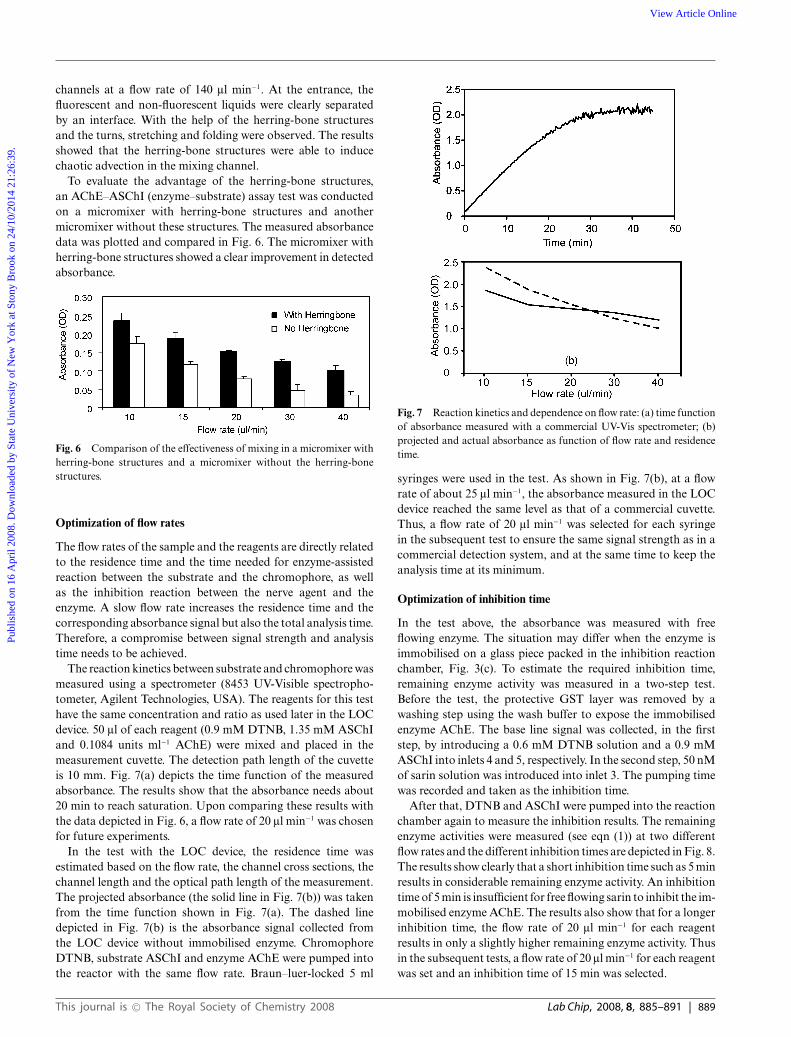
To evaluate the advantage of the herring-bone structures,an AChE–ASChI (enzyme–substrate) assay test was conductedon a micromixer with herring-bone structures and anothermicromixer without these structures. The measured absorbancedata was plotted and compared in Fig. 6. The micromixer withherring-bone structures showed a clear improvement in detectedabsorbance.
Fig. 6 Comparison of the effectiveness of mixing in a micromixer withherring-bone structures and a micromixer without the herring-bonestructures.
Optimization of flow rates
The flow rates of the sample and the reagents are directly relatedto the residence time and the time needed for enzyme-assistedreaction between the substrate and the chromophore, as wellas the inhibition reaction between the nerve agent and theenzyme. A slow flow rate increases the residence time and thecorresponding absorbance signal but also the total analysis time.Therefore, a compromise between signal strength and analysistime needs to be achieved.
The reaction kinetics between substrate and chromophore wasmeasured using a spectrometer (8453 UV-Visible spectropho-tometer, Agilent Technologies, USA). The reagents for this testhave the same concentration and ratio as used later in the LOCdevice. 50 ll of each reagent (0.9 mM DTNB, 1.35 mM ASChIand 0.1084 units ml−1 AChE) were mixed and placed in themeasurement cuvette. The detection path length of the cuvetteis 10 mm. Fig. 7(a) depicts the time function of the measuredabsorbance. The results show that the absorbance needs about20 min to reach saturation. Upon comparing these results withthe data depicted in Fig. 6, a flow rate of 20 ll min−1 was chosenfor future experiments.
In the test with the LOC device, the residence time wasestimated based on the flow rate, the channel cross sections, thechannel length and the optical path length of the measurement.The projected absorbance (the solid line in Fig. 7(b)) was takenfrom the time function shown in Fig. 7(a). The dashed linedepicted in Fig. 7(b) is the absorbance signal collected fromthe LOC device without immobilised enzyme. ChromophoreDTNB, substrate ASChI and enzyme AChE were pumped intothe reactor with the same flow rate. Braun–luer-locked 5 ml
Fig. 7 Reaction kinetics and dependence on flow rate: (a) time functionof absorbance measured with a commercial UV-Vis spectrometer; (b)projected and actual absorbance as function of flow rate and residencetime.
syringes were used in the test. As shown in Fig. 7(b), at a flowrate of about 25 ll min−1, the absorbance measured in the LOCdevice reached the same level as that of a commercial cuvette.Thus, a flow rate of 20 ll min−1 was selected for each syringein the subsequent test to ensure the same signal strength as in acommercial detection system, and at the same time to keep theanalysis time at its minimum.
Optimization of inhibition time
In the test above, the absorbance was measured with freeflowing enzyme. The situation may differ when the enzyme isimmobilised on a glass piece packed in the inhibition reactionchamber, Fig. 3(c). To estimate the required inhibition time,remaining enzyme activity was measured in a two-step test.Before the test, the protective GST layer was removed by awashing step using the wash buffer to expose the immobilisedenzyme AChE. The base line signal was collected, in the firststep, by introducing a 0.6 mM DTNB solution and a 0.9 mMASChI into inlets 4 and 5, respectively. In the second step, 50 nMof sarin solution was introduced into inlet 3. The pumping timewas recorded and taken as the inhibition time.
After that, DTNB and ASChI were pumped into the reactionchamber again to measure the inhibition results. The remainingenzyme activities were measured (see eqn (1)) at two differentflow rates and the different inhibition times are depicted in Fig. 8.The results show clearly that a short inhibition time such as 5 minresults in considerable remaining enzyme activity. An inhibitiontime of 5 min is insufficient for free flowing sarin to inhibit the im-mobilised enzyme AChE. The results also show that for a longerinhibition time, the flow rate of 20 ll min−1 for each reagentresults in only a slightly higher remaining enzyme activity. Thusin the subsequent tests, a flow rate of 20 ll min−1 for each reagentwas set and an inhibition time of 15 min was selected.
This journal is © The Royal Society of Chemistry 2008 Lab Chip, 2008, 8, 885–891 | 889
Publ
ishe
d on
16
Apr
il 20
08. D
ownl
oade
d by
Sta
te U
nive
rsity
of
New
Yor
k at
Sto
ny B
rook
on
24/1
0/20
14 2
1:26
:39.
View Article Online

Fig. 8 Remaining enzyme activity at different flow rates and inhibi-tion times.
Subsequently, the LOC device was tested with whole bloodsamples spiked with sarin. The experiments were designed toassess the effectiveness of the different stages of the LOC device.In the first experiment, the inhibition reactor (Fig. 3(d)) wastested with a blood sample prepared outside the LOC device,by-passing the nerve gas regeneration reactor, lysis reactor andfilter chamber. In the second experiment, the filter chamberand the inhibition reactor were tested, by-passing the nervegas regeneration reactor and the lysis reactor. In the finalexperiment, the whole system was tested with whole bloodspiked with sarin as the input sample.
Experiment 1: test of immobilised enzyme reaction chamber andabsorbance detection
To start, 200 ll of whole blood was spiked with 4 ll of sarin lead-ing to a concentration of 200 nM. Nerve gas regeneration chem-ical KF was added to spiked blood and left to react for 5 min.Next, the protein precipitation chemical SAS was added to theKF and spiked blood mixture. The mixture was then transferredinto a microplate containing filtration beads and filtered usingthe Whatman vacuum manifold. The filtrate was subsequentlycollected and transferred into a container that was kept on ice.
The test started with the washing step, where the wash bufferwas pumped at a flow rate of 60 ll min−1 through each inlet, 4 and5, into the inhibition reaction chamber to remove the protectiveGST layer and to expose the immobilised enzyme. Next, the baseline absorbance was measured, where both substrate ASChI (0.9mM) and chromophore DTNB (0.6 mM) were pumped at a flowrate of 20 ll min−1 into the LOC device. The cold blood filtratewas then pumped into the device at inlet 4 at a flow rate of60 ll min−1. Once immobilised the enzyme chamber was filledwith filtrate, the syringe pump was stopped and inhibition was al-lowed to take place inside the enzyme chamber for 15 min. Washbuffer was then pumped into the device through inlets 4 and 5to flush away the blood filtrate. Finally, DTNB and ASChI wereintroduced into the device through inlets 4 and 5 at a flow rate of20 ll min−1 each. The absorbance was then recorded accordingly.
Experiment 2: test of microfilters, immobilised enzyme reactionchamber and absorbance detection
In this test, the blood sample was prepared in the sameway as previously described and has a sarin concentration of200 nM. However, after mixing with KF and SAS, the sample
was not filtered. The washing step and the measurement of thebase line absorbance was the same as in experiment 1.
2.5 ml of the unfiltered blood mixture (spiked blood, KF,and SAS) was pumped into the LOC device at a flow rate of60 ll min−1 via inlet 3. The pumping process continued untilall the blood mixture had gone through the device. The entireexperiment took about 23–24 min. After the inhibition reaction,the measurement of the absorbance followed the same protocolas experiment 1.
Experiment 3: test of the complete LOC device
The washing step for removing the GST layer protectingthe immobilised enzyme followed the same protocol as inexperiments 1 and 2. The whole blood sample spiked with200 nM sarin was prepared outside of the LOC device.
The test started with the pumping of the spiked whole bloodsample, KF and SAS through inlets 1, 2 and 3, respectively. Asthe volume ratio between spiked blood, KF and SAS was to bekept at approx. 2 : 9 : 14, we used different volume syringes forthe respective reagents; i.e. 1 ml syringe for spiked blood, 5 mlsyringe for KF and 10 ml syringe for SAS. The flow rate of thepump was set with the 5 ml syringe as the reference. To checkthe effect of the residence time and the corresponding inhibitiontime, the flow rates at inlets 1, 2, and 3 were set at 48 ll min−1
(3 ll min−1 spiked blood, 15 ll min−1 KF, and 30 ll min−1 SAS)and 22.4 ll min−1 (1.4 ll min−1 spiked blood, 7 ll min−1 KF, and14 ll min−1 SAS). Three sets of experiments were conductedto ensure the repeatability of the test. The residence times wereapprox. 25 min and 65 min, respectively. After the inhibitionreaction, the measurement of the absorbance followed the sameprotocol as experiment 1.
Discussion
For all experiments, the required time for the washing step was1 to 2 h to entirely remove the GST layer. This time could beshortened using a higher flow rate and thus a higher shear stressor a thinner layer of GST to coat the immobilised enzyme.
Fig. 9 shows the remaining enzyme activities measured inall three experiments. Despite the different levels of inhibition,all experiments show the successful detection of sarin withrespect to a drop in absorbance. Experiment 2 shows clearlythat the sample cleanup absorbent packed in the device waseffective in removing the fluoride ions, and more than 50% of
Fig. 9 Remaining enzyme activity in the three testing experiments.
890 | Lab Chip, 2008, 8, 885–891 This journal is © The Royal Society of Chemistry 2008
Publ
ishe
d on
16
Apr
il 20
08. D
ownl
oade
d by
Sta
te U
nive
rsity
of
New
Yor
k at
Sto
ny B
rook
on
24/1
0/20
14 2
1:26
:39.
View Article Online

the immobilised enzyme was inhibited. The results show that on-chip sample preparation was even better than the conventionalprocess outside the LOC device.
The test of the whole LOC device in experiment 3 shows thatonly approx. 5% of the enzyme was inhibited at a total sampleflow rate of 48 ll min−1 and a corresponding total residence timeof 25 min. At this flow rate, the residence time in the regenerationreactor was about 1.5 min, while the protocol for preparationoutside the LOC required 3 min for the regeneration. Since theconditions for the filtering stage and the immobilisation stagewere the same as in experiments 1 and 2, the reason may be dueto inefficient mixing in the first two stages or the insufficientresidence time for the regeneration reaction.15 Measurementwith a slower total sample flow rate of 22.4 ll min−1 anda corresponding total residence time of 65 min supports thishypothesis. The inhibition rate of the enzyme was increased toapprox. 43%.
Conclusions
We report the design, fabrication and test of a LOC device for thedetection of regenerated nerve agent in human blood samples.The detection concept is based on the inhibition reactionbetween the nerve agent and an enzyme. The enzyme activity wastested by hydrolysis of a substrate. The extent of the hydrolysisreaction was measured with a chromophore. Detection of sarinin whole blood spiked with a low level sarin concentration,200 nM, was successfully achieved, shown as a significant drop inabsorbance. Experiments were carried out for the determinationof the kinetics of the inhibition reaction to estimate the requiredsample flow rate and inhibition time. The effectiveness of eachstage of the LOC device was tested in three separate experiments.The results showed that the immobilization and protectionof the enzyme on the chip was successful. The clear drop inabsorbance showed that the inhibition reactions were successfulin all three experiments. The lower remaining enzyme activityin experiment 2 showed that filtering and clean up of fluorideions on the chip was more effective than the on-the-benchprotocol. Compared to experiment 2, the results of experiment3 showed that improvement is needed to address the problemof effective mixing and required residence time. The currentrelatively long test time can be improved by optimising the
thickness of the GST layer and the washing protocol. Effectiveremoval of the protecting GST layer would shorten the analysistime significantly. Currently, the pumping and valving processeswere carried out outside the LOC. In the future, we aim toincorporate these processes into the chip to make it suitablefor easy use in portable applications. The device presented inthis paper can also be used for detection of organophosphorusinsecticides. Thus, the device is suitable for other applications inoccupational hygiene in agriculture.
Acknowledgements
Financial support from Defence Science and TechnologyAgency of Singapore, contract number MINDEF-NTU/05/08,is gratefully acknowledged.
References1 M. Pumera, J. Chromatogr., A, 2006, 1113, 5–13.2 http://www.opcw.nl.3 G. H. Seong, J. Heo and R. M. Crooks, Anal. Chem., 2003, 75,
3161–3167.4 S.-W. Zhang and T. M. Swager, J. Am. Chem. Soc., 2003, 125, 3420–
3421.5 A. L. Simonian, T. A. Good, S.-S. Wang and J. R. Wild, Anal. Chim.
Acta, 2005, 534, 69–77.6 L. Viveros, S. Paliwal, D. McCrae, J. Wild and A. Simonian, Sens.
Actuators, B, 2006, 115, 150–157.7 S. Bencic-Nagale, T. Sternfeld and D. R. Walt, J. Am. Chem. Soc.,
2006, 128, 5041–5048.8 A. G. Hadd, S. C. Jacobson and J. M. Ramsey, Anal. Chem., 1999,
71, 5206–5212.9 J. Wang, M. P. Chatrathi, A. Mulchandani and W. Chen, Anal. Chem.,
2001, 73, 1804–1808.10 M. Toner and D. Irimia, Annu. Rev. Biomed. Eng., 2005, 7, 77–103.11 R. H. Liu, J. Yang, R. Lenigk, J. Bonanno and P. Grodzinski, Anal.
Chem., 2004, 76, 1824–1831.12 D. S. Kim, S. H. Lee, C. H. Ahn, J. Y. Lee and T. H. Kwon, Lab Chip,
2006, 6, 794–802.13 Y. Sun, Y. C. Kwok and N. T. Nguyen, Lab Chip, 2007, 7, 1012–1017.14 H. Y. Tan, N.T Nguyen, W. K. Loke, Y. T. Tan, Proc. SPIE Smart
Materials, Nano- & Micro-Smart Systems Conf., Proceedings ofSPIE, 2006, vol. 6416, 23.
15 DSO National Laboratories, Patent Application No.PCT/SG2007/000406, Rapid Detection of Cholinesterase Inhibitors.
16 A. D. Stroock, S. K. W. Dertinger, A. Ajdari, I. Mezic, H. A. Stoneand G. M. Whitesides, Science, 2002, 295, 647–51.
17 Y. Sun, Y. C. Kwok and N. T. Nguyen, J. Micromech. Microeng.,2006, 16, 1681–1688.
This journal is © The Royal Society of Chemistry 2008 Lab Chip, 2008, 8, 885–891 | 891
Publ
ishe
d on
16
Apr
il 20
08. D
ownl
oade
d by
Sta
te U
nive
rsity
of
New
Yor
k at
Sto
ny B
rook
on
24/1
0/20
14 2
1:26
:39.
View Article Online