Embed Size (px)
Citation preview

Torsiflex Disc
Couplings
for General
Purpose
& Process
Applications
A l t r a I n d u s t r i a l M o t i o n
T o r s i f l e x D i s c C o u p l i n g s f o r G e n e r a l P u r p o s e a n d P r o c e s s A p p l i c a t i o n s
O D
O A
DBSEC C
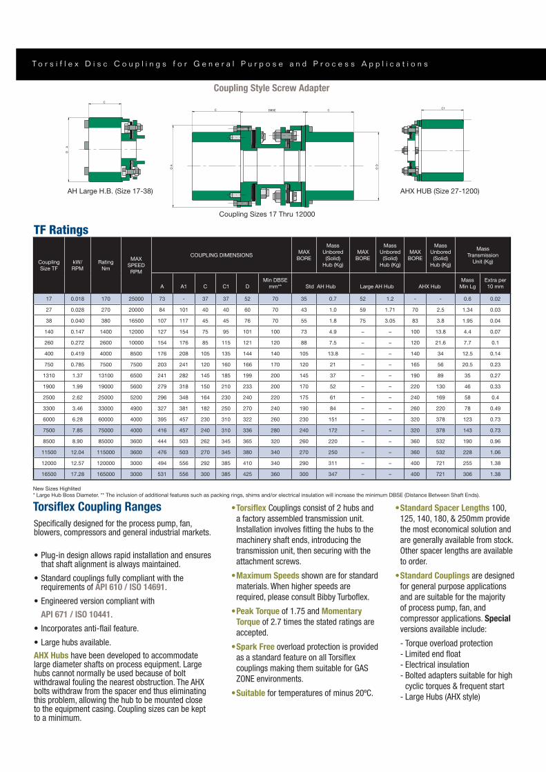
AHX HUB (SIZE 27-1200)
C1
AH LARGE HUB (SIZE 17-38)
OA
C
Torsi ex Coupling Ranges
Speci cally designed for the process pump, fan, blowers, compressors and general industrial markets.
that shaft alignment is always maintained.
requirements of API 610 / ISO 14691.
API 671 / ISO 10441.
Torsi ex Couplings consist of 2 hubs and
a factory assembled transmission unit.
machinery shaft ends, introducing the
transmission unit, then securing with the
attachment screws.
Maximum Speeds shown are for standard
materials. When higher speeds are
Peak Torque of 1.75 and Momentary
Torque of 2.7 times the stated ratings are
accepted.
Spark Free
couplings making them suitable for GAS
Suitable for temperatures of minus 20ºC.
Coupling Style Screw Adapter
Standard Spacer Lengths 100,
the most economical solution and
to order.
Standard Couplings are designed
for general purpose applications
and are suitable for the majority
of process pump, fan, and
compressor applications. Special
cyclic torques & frequent start
AHX Hubs
hubs cannot normally be used because of bolt
bolts withdraw from the spacer end thus eliminating this problem, allowing the hub to be mounted close to the equipment casing. Coupling sizes can be kept to a minimum.
Coupling
Size TF
kW/
RPM
Rating
Nm
MAX
SPEED
RPM
COUPLING DIMENSIONSMAX
BORE
Mass
Unbored
(Solid)
Hub (Kg)
MAX
BORE
Mass
Unbored
(Solid)
Hub (Kg)
MAX
BORE
Mass
Unbored
(Solid)
Hub (Kg)
Mass
Transmission
Unit (Kg)
A A1 C C1 D
Min DBSE
mm** Std AH Hub Large AH Hub AHX Hub
Mass
Min Lg
Extra per
10 mm
17 0.018 170 25000 73 - 37 37 52 70 35 0.7 52 1.2 - - 0.6 0.02
27 0.028 270 20000 84 101 40 40 60 70 43 1.0 59 1.71 70 2.5 1.34 0.03
38 0.040 380 16500 107 117 45 45 76 70 55 1.8 75 3.05 83 3.8 1.95 0.04
140 0.147 1400 12000 127 154 75 95 101 100 73 4.9 – – 100 13.8 4.4 0.07
260 0.272 2600 10000 154 176 85 115 121 120 88 7.5 – – 120 21.6 7.7 0.1
400 0.419 4000 8500 176 208 105 135 144 140 105 13.8 – – 140 34 12.5 0.14
750 0.785 7500 7500 203 241 120 160 166 170 120 21 – – 165 56 20.5 0.23
1310 1.37 13100 6500 241 282 145 185 199 200 145 37 – – 190 89 35 0.27
1900 1.99 19000 5600 279 318 150 210 233 200 170 52 – – 220 130 46 0.33
2500 2.62 25000 5200 296 348 164 230 240 220 175 61 – – 240 169 58 0.4
3300 3.46 33000 4900 327 381 182 250 270 240 190 84 – – 260 220 78 0.49
6000 6.28 60000 4000 395 457 230 310 322 260 230 151 – – 320 378 123 0.73
7500 7.85 75000 4000 416 457 240 310 336 280 240 172 – – 320 378 143 0.73
8500 8.90 85000 3600 444 503 262 345 365 320 260 220 – – 360 532 190 0.96
11500 12.04 115000 3600 476 503 270 345 380 340 270 250 – – 360 532 228 1.06
12000 12.57 120000 3000 494 556 292 385 410 340 290 311 – – 400 721 255 1.38
16500 17.28 165000 3000 531 556 300 385 425 360 300 347 – – 400 721 306 1.38
New Sizes Highlited
* Large Hub Boss Diameter. ** The inclusion of additional features such as packing rings, shims and/or electrical insulation will increase the minimum DBSE (Distance Between Shaft Ends).
TF Ratings
AH Large H.B. (Size 17-38)
Coupling Sizes 17 Thru 12000
AHX HUB (Size 27-1200)

w w w . b i b b y t u r b o f l e x . c o mO
D
O A
CC DBSE
OA
1
C1
Coupling Style Bolted Adapter
Service FactorsDriver Driven Service Factor (SF)
Turbines, Soft start
motors
Steady Torque 1.2
1.5
2
1.5
forced draught1.5
Cooling Tower
induced draught2
Selection Procedure
1.
2.
Select a coupling with suf cient rating
4. Check hub bore is capable of accommodating shafts
5.
selected
Specify required dynamic balance
7. Specify the distance between shaft ends and
check this is not less than the minimum for
the selected coupling
Distance between shaft end = 140mm
Selection TF0140L140 Screwed Adapter
or
Coupling
Size TF
kW/
RPM
Rating
Nm
MAX
SPEED
RPM
COUPLING DIMENSIONSMAX
BORE
Mass
Unbored
(Solid)
Hub (Kg)
MAX
BORE
Mass
Unbored
(Solid)
Hub (Kg)
Mass
Transmission
Unit (Kg)
A A1 C C1 D
Min DBSE
mm** Std LAH Hub Standard AHX Hub
Mass
Min Lg
Extra per
10 mm
140 0.147 1400 12000 154 154 85 95 117 100 84 7.5 100 13.8 5.1 0.07
260 0.272 2600 10000 176 176 105 115 138 120 99 12.8 120 21.6 8 0.1
400 0.419 4000 8500 203 204 120 135 158 140 113 19.2 140 34 13.2 0.14
750 0.785 7500 7500 241 241 145 160 190 170 136 33.5 165 56 23.4 0.23
1310 1.37 13100 6500 282 282 150 185 230 200 164 50.6 190 89 39 0.27
1900 1.99 19000 5600 318 318 150 210 262 200 187 65.9 220 130 39 0.33
2230 2.34 22300 5600 318 318 160 210 262 220 187 70.1 220 130 45 0.33
2500 2.62 25000 5200 332 348 164 230 276 220 197 79 240 169 51 0.4
3200 3.35 32000 5200 348 348 175 230 292 240 209 95 240 169 63 0.4
3300 3.46 33000 4900 364 381 182 250 302 240 216 106 260 220 68 0.49
4800 5.03 48000 4900 381 381 200 250 310 260 221 123 260 220 79 0.58
6000 6.28 60000 4000 436 457 230 310 358 260 256 188 320 378 106 0.73
7500 7.85 75000 4000 457 457 240 310 370 280 264 210 320 378 123 0.73
8500 8.90 85000 3600 484 503 262 345 400 320 286 264 360 532 163 0.96
11500 12.04 115000 3600 503 503 270 345 415 340 296 295 360 532 190 1.06
12000 12.57 120000 3000 540 556 292 385 444 340 317 366 400 721 216 1.38
16500 17.28 165000 3000 556 556 300 385 456 360 326 395 400 721 250 1.38
New Sizes Highlited
* Large Hub Boss Diameter. ** The inclusion of additional features such as packing rings, shims and/or electrical insulation will increase the minimum DBSE (Distance Between Shaft Ends).
AHX HUB (Size 140-16500)

T o r s i f l e x D i s c C o u p l i n g s f o r G e n e r a l P u r p o s e a n d P r o c e s s A p p l i c a t i o n s
Type TFCFT Composite Tube (“Plug-in”) Couplings
SizeApplicable
Tube
Dimensions
KNm A1 A C D
140 0.147 1400 127 101
0.272 88 154 115 121
400 4000 105 144
750 0.785 7500 120
145 241 185
170 210
2500 25000 175 240
250 270
T8 570 471
8500 85000 T8 570 471 444
12000 12.57 120000 517 410
Single Span Con guration
1500 1000 750
4.5 5.2 0.8
T4 4.5 5.5 0.8
T5 5.1 0.8
4.1 5.7 7.1 8.2 1
T7 4.4 7.7 1
T8 4.8 8.4 1.5
5 7.1 8.7 1.5
Special features can be designed into the coupling
D
C
E
DBSE
E
C
A
Button. The Thrust Button is used to
operation.
Taper Bush use in the hub at one end of
upon installation. Other clamp systems can also be incorporated into the designs.
w w w . b i b b y t u r b o f l e x . c o m
Type TFCFT Composite Tube (“Plug-in”) Couplings
couplings has been designed using the
lower mass and greater strength. This
type of unit was, originally, designed to
meet the requirements of cooling towers
but has since been adapted to meet the
been designed and supplied for use in
shafts and high speed test beds.
The tubes are lament wound on
accurate mandrels using computer
controlled machinery. The resulting tube
is cured whilst on the mandrel.
This process leads to high accuracy with
regard to tube dimensions, roundness
and straightness all of which aid in the
optimum performance for speci c lateral
critical, torque and torsional stiffness
requirements.
This is the principle
mass option for the tubes. This is
considered as the standard for the
Glass bre offers a low
cost solution for many applications of
moderate length. The mass to stiffness
applications to which they are ideally
suited.
The bre winding
enables us to combine these materials
the optimum solution for a speci c
application.
Due to its high
high modulus bre is generally only
The tubes are wrapped in a pigment
protect them against physical damage
Type TFCFT Composite Tube (“Plug-in”) Couplings
Cooling Tower Fan Drives
long lengths without central bearings,
combined with their inherently low mass
and generous misalignment capacity,
keeps maintenance of the equipment to a
minimum. The maintenance free nature
The design is such as to make site
assembly as easy as possible.
The units can be supplied in standard
coatings or, if required, in stainless steel.
Vertical Pump Drives
deep well pump applications such as
encountered in water & sewage pumping
without the need for central bearings and
their inherent low mass can considerably
reduce maintenance costs on units.
operated or inaccessible plants especially
couplings.
the requirements of particular
applications.
ways which, when coupled with the
generous misalignment capacity and ease
of assembly design, can reduce
installation time.
When necessary, thrust pins can be added
to the unit to support the mass of the
central spacer.
Marine Drives
long spans without support bearings,
applications.
Special Applications
composite spacer shafts are used in many
special applications. Their low mass & low
inertia, coupled with the ability to adjust
the torsional & lateral characteristics of
them applicable for many cases where
inappropriate. Whilst the application for
these shafts is as wide as that for
has been found in marine applications,
test beds.
Whilst the composite shafting is primarily
disc couplings, it can equally well be
incorporated into any other of our wide
range of products.

T o r s i f l e x D i s c C o u p l i n g s f o r G e n e r a l P u r p o s e a n d P r o c e s s A p p l i c a t i o n s
Installation Alignment
Recommended Installation Alignments shown as % of the Maximum Permitted values for the Couplings
Allowable Angular / Radial Misalignment Allowable Axial Misalignment
Note: Angular / Radial as percentage of stated value for ‘Point A’. Axial as percentage of stated value for ‘Point C’.
Misalignment DataThese will be supplied upon request with
assessment at preliminary stages.
The methods of machinery alignment
Simple recommended methods are
The following is a guide to acceptable
misalignments at installation.
are MAXIMUM
the allowance for misalignment due to
machinery settlement, etc. thus ensuring
greater machinery life and trouble free
operation of the coupling.
Angle 1Angle 2
Radial
TF Misalignment
Coupling
Bending
Thrust
Thrust
17 0.5 tba 1.2 0.25 28
27 .05 tba 1.5 450 40
0.5 tba 2 470 0.5 42
140 0.5 2.4 1082 0.5 81
0.5 20 0.7 151
400 0.5 1.2
750 0.5 50 5440 1.5
0.5 82 5.5 7800 1.8
4.4 1.4 1070
4.8
2500 172 4.8 1.5 1214
15775 1784
4800 5.2 18500 1.5 1820
20100 2.1
7500 457 24000 2
8500 504 7.2 2.5
11500 2.1
12000 8.1 2.8
8 41850
Type TF - MaterialsThe following standard materials of
applications on request.
material
Axial Angular
Radial
De#nition of Misalignment
AngularAxial
Radial
Angular & Radial Misalignment in ‘Combination’
Radial
Angle 1Angle 2
Combined Angular/Parallel Misalignment
Axial Deflection (±)
b
a
c C
A B
Allowable Misalignments for Disc Couplings
w w w . b i b b y t u r b o f l e x . c o m
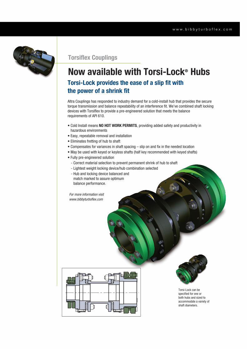
Torsiflex Couplings
Now available with Torsi-Lock® HubsTorsi-Lock provides the ease of a slip fit with
the power of a shrink fit
specified for one or
both hubs and sized to
shaft diameters.
NO HOT WORK PERMITS
match marked to assure optimum
balance performance.
For more information visit
www.bibbyturboflex.com

www.bibbyturbo ex.com
Cannon Way, Dewsbury,West Yorkshire, WF13 1EH – United Kingdom+ 44(0) 1924 460801 Fax: + 44(0) 1924 457668 P-1943-BB 3/14 Printed in USA
Altra Industrial Motion All Customer Service phone numbers shown in bold
Electromagnetic Clutches and Brakes
Warner Electric
Electromagnetic Clutches and Brakes
New Hartford, CT - USA 1-800-825-6544
For application assistance:
1-800-825-9050
St Barthelemy d’Anjou, France +33 (0) 2 41 21 24 24
Precision Electric Coils and Electromagnetic Clutches and Brakes
Columbia City, IN - USA 1-260-244-6183
Matrix International
Electromagnetic Clutches and Brakes, Pressure Operated Clutches and Brakes
Brechin, Scotland +44 (0) 1356 602000
New Hartford, CT - USA 1-800-825-6544
Inertia Dynamics
Spring Set Brakes; Power On and Wrap Spring Clutch/Brakes
New Hartford, CT - USA 1-800-800-6445
Linear Products
Warner Linear
Linear Actuators
Belvidere, IL - USA 1-800-825-6544
For application assistance:
1-800-825-9050
St Barthelemy d’Anjou, France +33 (0) 2 41 21 24 24
Couplings
Ameridrives Couplings
Mill Spindles, Ameriflex, Ameridisc
Erie, PA - USA 1-814-480-5000
Gear Couplings
San Marcos, TX - USA 1-800-458-0887
Bibby Turboflex
Disc, Gear, Grid Couplings, Overload Clutches
Dewsbury, England +44 (0) 1924 460801
Boksburg, South Africa +27 11 918 4270
TB Wood’s
Elastomeric Couplings
Chambersburg, PA - USA 1-888-829-6637– Press #5
For application assistance:
1-888-829-6637 – Press #7
General Purpose Disc Couplings
San Marcos, TX - USA 1-888-449-9439
Ameridrives Power Transmission
Universal Joints, Drive Shafts, Mill Gear Couplings
Green Bay, WI - USA 1-920-593-2444
Huco Dynatork
Precision Couplings and Air Motors
Hertford, England +44 (0) 1992 501900
Chambersburg, PA - USA 1-888-829-6637
Lamiflex Couplings
Flexible Couplings, Bearing Isolators, and Coupling Guards
São Paulo, SP - Brasil +55-11-5679-6533
Heavy Duty Clutches and Brakes
Wichita Clutch
Pneumatic Clutches and Brakes
Wichita Falls, TX - USA 1-800-964-3262
Bedford, England +44 (0) 1234 350311
Twiflex Limited
Caliper Brakes and Thrusters
Twickenham, England +44 (0) 20 8894 1161
Industrial Clutch
Pneumatic and Oil Immersed Clutches and Brakes
Waukesha, WI - USA 1-262-547-3357
Gearing
Boston Gear
Enclosed and Open Gearing, Electrical and Mechanical P.T. Components
Charlotte, NC - USA 1-800-825-6544
For application assistance:
1-800-816-5608
Bauer Gear Motor
Geared Motors
Esslingen, Germany +49 (711) 3518 0
Somerset, NJ - USA 1-732-469-8770
Nuttall Gear and Delroyd Worm Gear
Worm Gear and Helical Speed Reducers
Niagara Falls, NY - USA 1-716-298-4100
Overrunning Clutches
Formsprag Clutch
Overrunning Clutches and Holdbacks
Warren, MI - USA 1-800-348-0881– Press #1
For application assistance:
1-800-348-0881 – Press #2
Marland Clutch
Roller Ramp and Sprag Type Overrunning Clutches and Backstops
South Beloit, IL - USA 1-800-216-3515
Stieber Clutch
Overrunning Clutches and Holdbacks
Heidelberg, Germany +49 (0) 6221 30 47 0
Belted Drives and Sheaves
TB Wood’s
Belted Drives
Chambersburg, PA - USA 1-888-829-6637 – Press #5
For application assistance:
1-888-829-6637 – Press #7
EngineeredBearing Assemblies
Kilian Manufacturing
Engineered Bearing Assemblies
Syracuse, NY - USA 1-315-432-0700
For information concerning our
sales offices in Asia Pacific
check our website
www.altramotion.com.cn

![Member stability of stainless steel welded I-section beam-columns · 2020. 1. 9. · 1993-1-4 [24]. The non-dimensional lateral-torsi onal buckling slenderness [24] of the members](https://img.pdfslide.us/doc/110x75/60e654d09bd4e359dc266619/member-stability-of-stainless-steel-welded-i-section-beam-columns-2020-1-9.jpg)