Embed Size (px)
Citation preview
Zhenhua ZhangDepartment of Mechanical Engineering,
Wichita State University,
Wichita, KS 67260
e-mail: [email protected]
Liang XuDepartment of Mechanical Engineering,
Wichita State University,
Wichita, KS 67260
e-mail: [email protected]
Paulo FloresDepartamento de Engenharia Mecanica,
Universidade do Minho,
Campus de Azur�em,
4800-058 Guimar~aes, Portugal
e-mail: [email protected]
Hamid M. LankaraniDepartment of Mechanical Engineering,
Wichita State University,
Wichita, KS 67260
e-mail: [email protected]
A Kriging Model for Dynamicsof Mechanical Systems WithRevolute Joint ClearancesOver the past two decades, extensive work has been conducted on the dynamic effect ofjoint clearances in multibody mechanical systems. In contrast, little work has beendevoted to optimizing the performance of these systems. In this study, the analysis of rev-olute joint clearance is formulated in terms of a Hertzian-based contact force model. Forillustration, the classical slider-crank mechanism with a revolute clearance joint at thepiston pin is presented and a simulation model is developed using the analysis/designsoftware MSC.ADAMS. The clearance is modeled as a pin-in-a-hole surface-to-surface drycontact, with an appropriate contact force model between the joint and bearing surfaces.Different simulations are performed to demonstrate the influence of the joint clearancesize and the input crank speed on the dynamic behavior of the system with the joint clear-ance. In the modeling and simulation of the experimental setup and in the followed para-metric study with a slightly revised system, both the Hertzian normal contact force modeland a Coulomb-type friction force model were utilized. The kinetic coefficient of frictionwas chosen as constant throughout the study. An innovative design-of-experiment(DOE)-based method for optimizing the performance of a mechanical system with therevolute joint clearance for different ranges of design parameters is then proposed. Basedon the simulation model results from sample points, which are selected by a Latin hyper-cube sampling (LHS) method, a polynomial function Kriging meta-model is establishedinstead of the actual simulation model. The reason for the development and use of themeta-model is to bypass computationally intensive simulations of a computer model fordifferent design parameter values in place of a more efficient and cost-effective mathe-matical model. Finally, numerical results obtained from two application examples withdifferent design parameters, including the joint clearance size, crank speed, and contactstiffness, are presented for the further analysis of the dynamics of the revolute clearancejoint in a mechanical system. This allows for predicting the influence of design parameterchanges, in order to minimize contact forces, accelerations, and power requirements dueto the existence of joint clearance. [DOI: 10.1115/1.4026233]
Keywords: Revolute joint clearance, contact forces, multibody dynamics, Kriging meta-model, genetic algorithms
1 Introduction
In the past decade, many researchers have examined the opti-mal dynamical solution of different mechanical systems andmechanisms [1–3]. Additionally, different optimization methodshave been implemented to obtain optimal solutions. In the studyby Laribi et al. [2], a solution for the path generation problem inmechanisms was presented using the generic algorithm-fuzzylogic method. Selcuk et al. [3] proposed a neural-genetic methodto investigate the effects of joints with clearance on its path gener-ation and kinematic transmission quality. In order to reduce thecomputational complexity, the neural network has been used as asurrogate model in this study. The Genetic algorithm, as a globaloptimization method, has been widely used in many researchfields, but its associated computational cost dramaticallyincreases, especially for expensive model functions.
As a result of manufacturing tolerances, material deformations,and wear after a certain working period, clearances between me-chanical components of mechanical systems occur in most kine-matic joints. Excessive clearance values result in large contactforces at the joints, especially during high-speed mechanical oper-ations. The presence of clearances leads to a decrease in the sys-
tem reliability and durability of the system’s components andmachines [4,5]. Over the past decades, advances, mainly due tothe development of intercross applications between computer-aided analysis of mechanical systems and optimization methodol-ogies, have been achieved. These results could be utilized for theapplication of different mathematical programming techniques tothe parametrical and topological syntheses and analyses of me-chanical systems [6]. The optimization of mechanical systemmodeling with clearances can be used to bypass the computation-ally intensive simulation of the computer dynamic model. It alsohelps in the analysis, design, and control of the dynamic perform-ance of a complex mechanical system and in quantifying the influ-ence of clearance parameters.
During the past two decades, many studies on the influence ofthe joint clearance in planar and spatial multibody mechanicalsystems have been conducted. Dubowsky and Freudenstein devel-oped the impact ring model, which is a simple model to demon-strate the effects of joint clearance in planar mechanisms [7].Springs and dashpots were arranged in their model to predict thedynamics response of the mechanical system. Dubowsky andMoening quantified the interaction between the clearance jointsand the mechanical system elasticity using a Scotch–Yoke simula-tion model [8]. Large impact forces developed at the clearancejoints caused a failure in the Scotch–Yoke model. Furubashi andMorita presented a four-bar mechanism with multiple clearancerevolute joints [9]. They analyzed and compared the results for
Contributed by the Design Engineering Division of ASME for publication in theJOURNAL OF COMPUTATIONAL AND NONLINEAR DYNAMICS. Manuscript received August1, 2013; final manuscript received December 10, 2013; published online February13, 2014. Assoc. Editor: Ahmet S. Yigit.
Journal of Computational and Nonlinear Dynamics JULY 2014, Vol. 9 / 031013-1Copyright VC 2014 by ASME
Downloaded From: http://computationalnonlinear.asmedigitalcollection.asme.org/ on 02/21/2014 Terms of Use: http://asme.org/terms
different numbers and various combinations of clearance jointsand demonstrated the effect of clearances on the performance ofthe four-bar mechanism system.
Lankarani and Nikravesh extended the Hertz contact law toinclude a hysteresis damping function and represent the dissipatedenergy during impact [10]. A nonlinear continuous force acted onthe model and the local indentation and relative penetration veloc-ity was related to the contact force. Flores and his coworkersdeveloped a precise model for the dynamic analysis of a mechani-cal system with dry and lubricated revolute joints [11–13]. Theinfluences of the selected parameters on the dynamic response ofmechanical systems with multiple clearance joints, including theclearance size, input crank speed, and number of joints modeledas clearance joints, were quantified in this study.
Mahrus designed a set of experimental investigations to showthe performance of the journal bearing and the effect of the loaddiagram on hydrodynamic lubrication [14]. Different loads wereapplied to the test journal-bearing joint and both steady and vary-ing unidirectional and full two-component dynamic loading wereconsidered in the study. Wilson and Fawcett modeled a slider-crank mechanism with a clearance in the sliding bearing to mea-sure the transverse motion of the slider [15]. They tested a numberof parameters such as the geometry, speed, and mass distributionof the mechanical system, which influence the transverse motionand they derived the equation of motion with these parametersbased on the results. Haines derived the equations of motion for amultibody mechanical system that describes the contributions at arevolute clearance joint with no lubrication present [16]. Thestudy also included an experimental investigation on the dynamicresponse of revolute clearance joints. Under static loading, thedeflection associated with contact elasticity in the dry journal-bearing joint was found to be much greater and linear than pre-dicted [17]. Bengisu et al. developed a four-bar mechanism basedon zero-clearance analysis to compare the theoretical results withthe experimental results [18]. A model with multiple joints wasused in clearances to study contact energy loss in the mechanicalsystem.
Feng et al. developed a method for optimizing the mass distri-bution of planar linkage with clearance joints to control thechange of inertia forces [19]. Tsai and Lai investigated the kine-matic sensitivity of the transmission performance of linkages withjoint clearances [20]. In their study, loop-closure equations wereused in the position analysis of a four-bar mechanism in which alljoints have clearances. Yildirim et al. predicted the transmissionangle of a slider-crank mechanism with an eccentric connectorbased on neural networks [21]. The neural network structure wasa feed-forward network and the best approximation was obtainedwith five types of algorithms. Erkaya and Uzmay studied theeffects of joint clearances on the performance of a mechanism interms of path generation and transmission angle, using neural net-works and genetic algorithms (GAs), respectively [3,21].
A computer-aided analysis of multibody mechanical systems isutilized in this study as a simulation model. The goal of this studyis to use the Kriging mathematical model as a design-of-experi-ments optimization tool, in order to demonstrate the influence ofthe design variables on the dynamic performance of mechanicalsystems with revolute clearance joints. The reason the Krigingmodel was used in this research is that the computer simulationfor a given set of design parameters is usually quite computation-ally intensive and each simulation for a given set of design varia-bles could take extensive computation time. Because there arewide ranges of values in the design variables such as the clearancesizes, ratios of length, material properties, contact stiffnesses, andspeeds of operation, studying the effects of each of these variableswould take enormous computational time and effort.
In the present study, the mathematical formulation of the revo-lute clearance joint is fully described and the relationship betweenthe design parameters and contact forces in joints is examined.First, the classical slider-crank mechanical system is modeled andsimulated in MSC.ADAMS and the performance of the system withdifferent sets of parameters is examined. Next, the theoretical ba-sis of the methods are stated, illustrating the framework for theDOE methods of the Latin hypercube sampling, Kriging meta-model, and genetic algorithm. Next, two simple examples are pre-sented using these previous methods to further expand the analysisof the dynamic behavior of the mechanism with the revolute clear-ance joint at different ranges of the design parameters.
2 Modeling Revolute Joints With Clearance
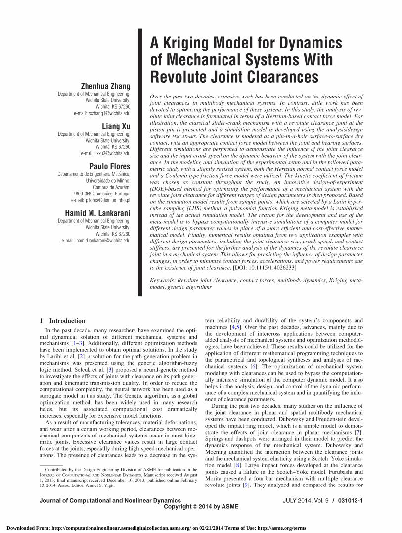
A revolute joint with clearance, as shown in Fig. 1, can bedescribed as a movable journal assembled inside a bearing, withthe journal’s and bearing’s radii of RJ and RB, respectively. Inreality, there is a clearance between the journal and the bearing inmechanical systems in order to cause a relative motion betweenthe two. The journal can move inside the bearing and this will addsome degrees of freedom to the system. The difference betweenthe radius of the bearing and the radius of the journal is the radialclearance size c. The penetration between the bearing and journalappears when they are in contact.
The indentation depth due to the contact impact between thejournal and the bearing can be defined as
d ¼ e� c (1)
where e is the magnitude of the eccentricity and c is the radialclearance. The eccentricity is evaluated as
e ¼ffiffiffiffiffiffiffiffiffiffiffiffiffiffiffiffiffiffiffiffiffiffiffiDX2 þ DY2
p(2)
where DX and DY are the horizontal and vertical displacements,respectively, measured from the state when the centers of the
Fig. 1 Revolute joint with clearance (clearance exaggerated for clarity)
031013-2 / Vol. 9, JULY 2014 Transactions of the ASME
Downloaded From: http://computationalnonlinear.asmedigitalcollection.asme.org/ on 02/21/2014 Terms of Use: http://asme.org/terms
journal and the bearing coincide. In turn, the radial clearance isdefined as
c ¼ RB � RJ (3)
Two situations can occur at the joint. In the first case, when thejournal does not make contact with the bearing and the penetrationdepth is a negative value, the journal has a free-flight motioninside the bearing and, thus, there is no contact-impact forcedeveloped at the joint. In the second case, when the journal con-tacts with the bearing wall, a contact force between the journaland the bearing is developed in the direction of the centers of thebearing and the journal [4] and the indentation depth value will begreater than zero.
The contact-impact force FN, in relation to the penetration in-dentation, can be modeled by the Hertz law as [10]
FN ¼ Kdn (4)
where K is the stiffness coefficient and d is the indentation depthgiven by Eq. (1). The exponent n is usually set for analysis in therange of 1.5–2.5 for most metal-to-metal contact. The stiffnesscoefficient K depends on the material properties and the contact-ing surface and is defined as
K ¼ 4
3ðrB þ rJÞRBRJ
RB � RJ
� �1=2
(5)
The material parameters rB and rJ are defined as
rk ¼1� �2
k
Ekk ¼ B; Jð Þ (6)
where the variables �k and Ek are Poisson’s ratio and Young’smodulus, respectively, for the journal and the bearing.
The Hertz law given by Eq. (4) does not include any energy dis-sipation. Lankarani and Nikravesh [10] extended the Hertz modelto include a hysteresis damping function as follows:
FN ¼ Kdn 1þ 3ð1� c2eÞ
4
_d_dð�Þ
" #(7)
where the stiffness coefficient K can be obtained from Eqs. (5)and (6)], ce is the restitution coefficient, _d is the relative penetra-tion velocity, and _dð�Þ is the initial impact velocity.
3 A Multibody System With Joint Clearance
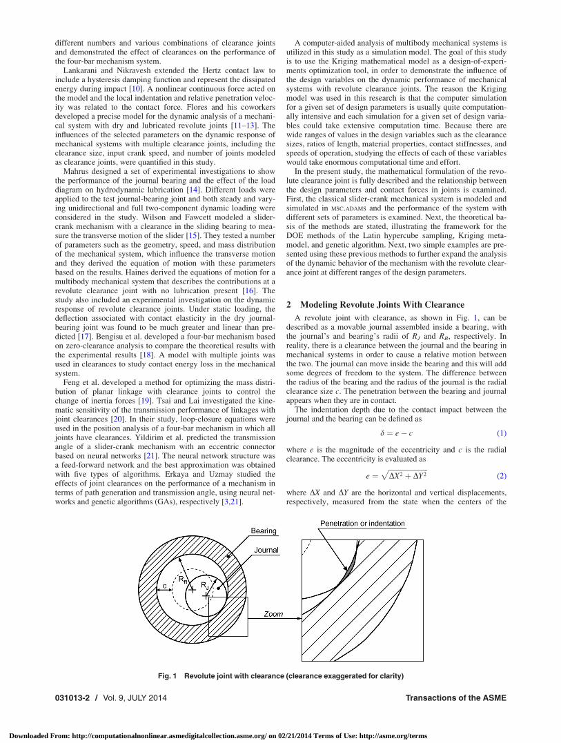
In this section, a computer model for the classic slider-crankmechanism with one revolute clearance joint is considered inorder to analyze the dynamic behavior of the mechanical system.Figure 2 shows the configuration of the slider-crank mechanism,which comprises four bodies that represent the crank, connectingrod, slider, and ground. In this case, the multibody model has onlyone clearance joint. There are four joints: two ideal revolute jointsbetween the ground and the crank and the crank and the connect-ing rod; one ideal translational joint between the slider andground; and one nonideal revolute joint clearance between theconnecting rod and slider. The geometric and inertia properties ofeach body in this system are shown in Table 1 [17]. The momentof inertia is taken with respect to the center of gravity of the body.
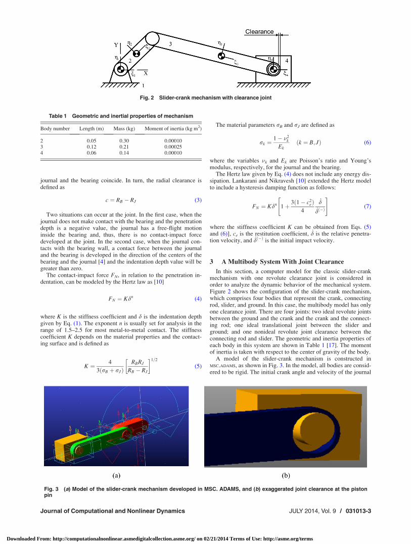
A model of the slider-crank mechanism is constructed inMSC.ADAMS, as shown in Fig. 3. In the model, all bodies are consid-ered to be rigid. The initial crank angle and velocity of the journal
Fig. 2 Slider-crank mechanism with clearance joint
Table 1 Geometric and inertial properties of mechanism
Body number Length (m) Mass (kg) Moment of inertia (kg m2)
2 0.05 0.30 0.000103 0.12 0.21 0.000254 0.06 0.14 0.00010
Fig. 3 (a) Model of the slider-crank mechanism developed in MSC. ADAMS, and (b) exaggerated joint clearance at the pistonpin
Journal of Computational and Nonlinear Dynamics JULY 2014, Vol. 9 / 031013-3
Downloaded From: http://computationalnonlinear.asmedigitalcollection.asme.org/ on 02/21/2014 Terms of Use: http://asme.org/terms
center are set to zero and the journal and bearing centers are coin-cident. The dynamic parameters used in the simulation are listedin Table 2.
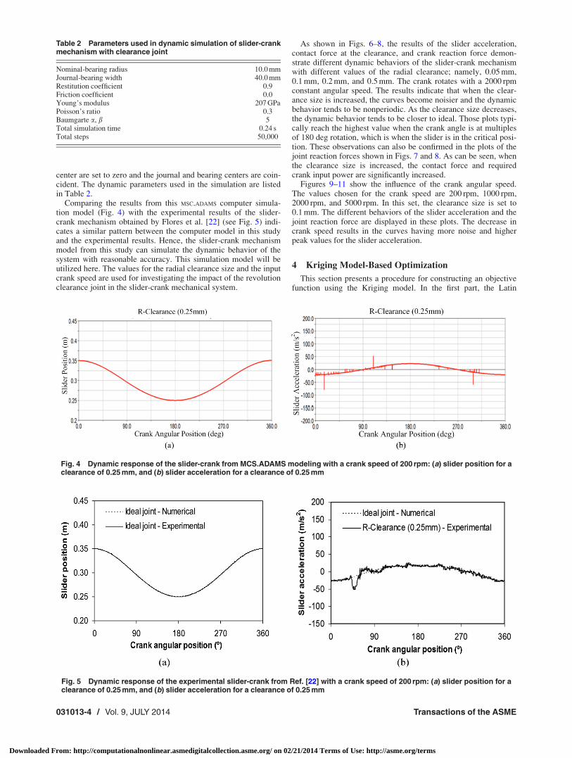
Comparing the results from this MSC.ADAMS computer simula-tion model (Fig. 4) with the experimental results of the slider-crank mechanism obtained by Flores et al. [22] (see Fig. 5) indi-cates a similar pattern between the computer model in this studyand the experimental results. Hence, the slider-crank mechanismmodel from this study can simulate the dynamic behavior of thesystem with reasonable accuracy. This simulation model will beutilized here. The values for the radial clearance size and the inputcrank speed are used for investigating the impact of the revolutionclearance joint in the slider-crank mechanical system.
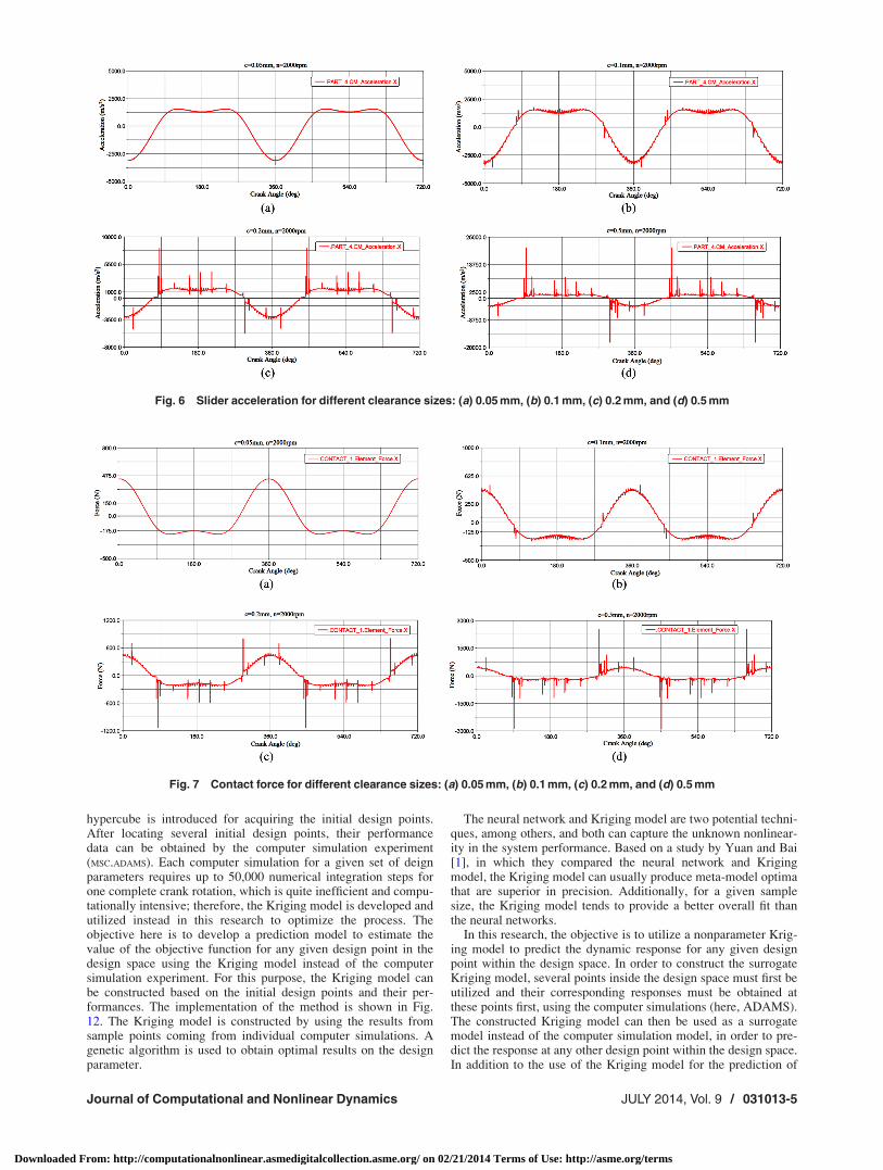
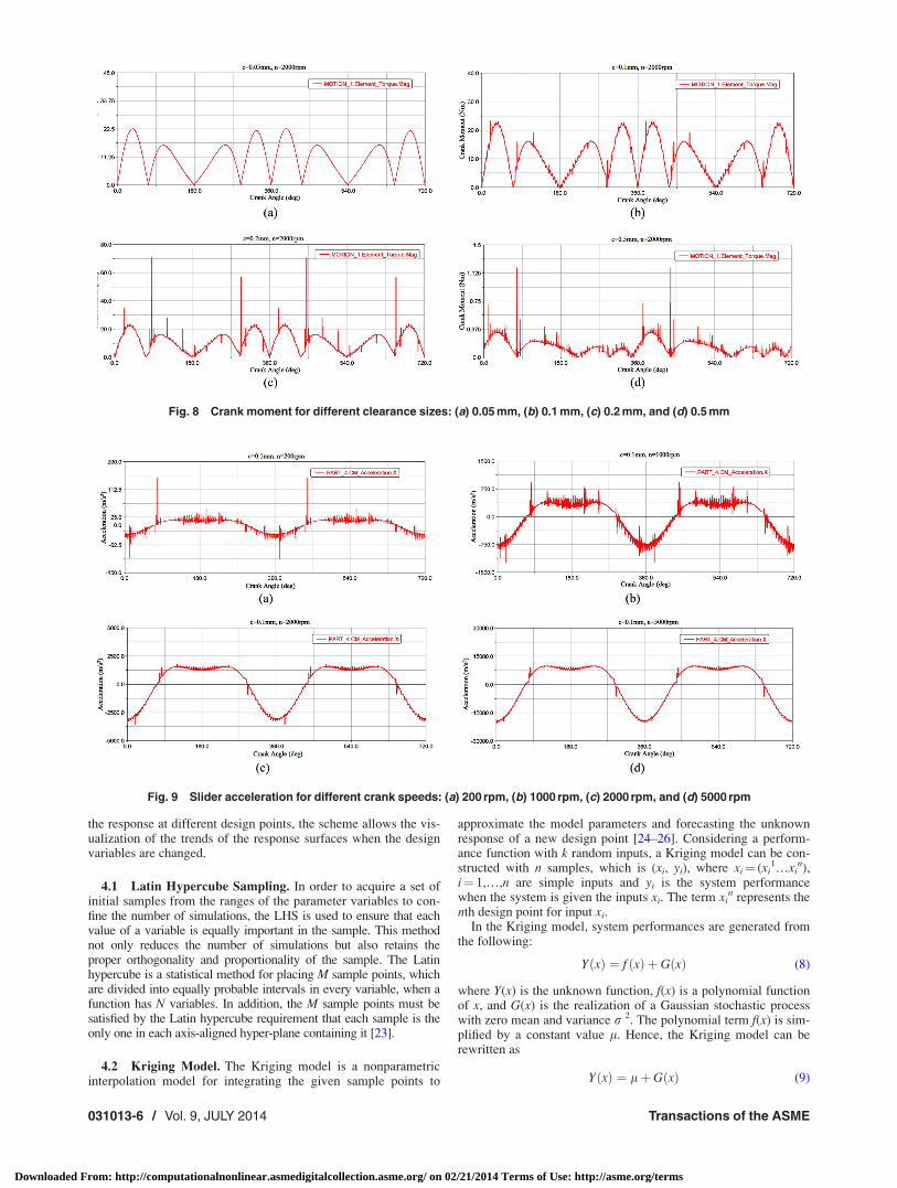
As shown in Figs. 6–8, the results of the slider acceleration,contact force at the clearance, and crank reaction force demon-strate different dynamic behaviors of the slider-crank mechanismwith different values of the radial clearance; namely, 0.05 mm,0.1 mm, 0.2 mm, and 0.5 mm. The crank rotates with a 2000 rpmconstant angular speed. The results indicate that when the clear-ance size is increased, the curves become noisier and the dynamicbehavior tends to be nonperiodic. As the clearance size decreases,the dynamic behavior tends to be closer to ideal. Those plots typi-cally reach the highest value when the crank angle is at multiplesof 180 deg rotation, which is when the slider is in the critical posi-tion. These observations can also be confirmed in the plots of thejoint reaction forces shown in Figs. 7 and 8. As can be seen, whenthe clearance size is increased, the contact force and requiredcrank input power are significantly increased.
Figures 9–11 show the influence of the crank angular speed.The values chosen for the crank speed are 200 rpm, 1000 rpm,2000 rpm, and 5000 rpm. In this set, the clearance size is set to0.1 mm. The different behaviors of the slider acceleration and thejoint reaction force are displayed in these plots. The decrease incrank speed results in the curves having more noise and higherpeak values for the slider acceleration.
4 Kriging Model-Based Optimization
This section presents a procedure for constructing an objectivefunction using the Kriging model. In the first part, the Latin
Table 2 Parameters used in dynamic simulation of slider-crankmechanism with clearance joint
Nominal-bearing radius 10.0 mmJournal-bearing width 40.0 mmRestitution coefficient 0.9Friction coefficient 0.0Young’s modulus 207 GPaPoisson’s ratio 0.3Baumgarte a, b 5Total simulation time 0.24 sTotal steps 50,000
Fig. 4 Dynamic response of the slider-crank from MCS.ADAMS modeling with a crank speed of 200 rpm: (a) slider position for aclearance of 0.25 mm, and (b) slider acceleration for a clearance of 0.25 mm
Fig. 5 Dynamic response of the experimental slider-crank from Ref. [22] with a crank speed of 200 rpm: (a) slider position for aclearance of 0.25 mm, and (b) slider acceleration for a clearance of 0.25 mm
031013-4 / Vol. 9, JULY 2014 Transactions of the ASME
Downloaded From: http://computationalnonlinear.asmedigitalcollection.asme.org/ on 02/21/2014 Terms of Use: http://asme.org/terms
hypercube is introduced for acquiring the initial design points.After locating several initial design points, their performancedata can be obtained by the computer simulation experiment(MSC.ADAMS). Each computer simulation for a given set of deignparameters requires up to 50,000 numerical integration steps forone complete crank rotation, which is quite inefficient and compu-tationally intensive; therefore, the Kriging model is developed andutilized instead in this research to optimize the process. Theobjective here is to develop a prediction model to estimate thevalue of the objective function for any given design point in thedesign space using the Kriging model instead of the computersimulation experiment. For this purpose, the Kriging model canbe constructed based on the initial design points and their per-formances. The implementation of the method is shown in Fig.12. The Kriging model is constructed by using the results fromsample points coming from individual computer simulations. Agenetic algorithm is used to obtain optimal results on the designparameter.
The neural network and Kriging model are two potential techni-ques, among others, and both can capture the unknown nonlinear-ity in the system performance. Based on a study by Yuan and Bai[1], in which they compared the neural network and Krigingmodel, the Kriging model can usually produce meta-model optimathat are superior in precision. Additionally, for a given samplesize, the Kriging model tends to provide a better overall fit thanthe neural networks.
In this research, the objective is to utilize a nonparameter Krig-ing model to predict the dynamic response for any given designpoint within the design space. In order to construct the surrogateKriging model, several points inside the design space must first beutilized and their corresponding responses must be obtained atthese points first, using the computer simulations (here, ADAMS).The constructed Kriging model can then be used as a surrogatemodel instead of the computer simulation model, in order to pre-dict the response at any other design point within the design space.In addition to the use of the Kriging model for the prediction of
Fig. 6 Slider acceleration for different clearance sizes: (a) 0.05 mm, (b) 0.1 mm, (c) 0.2 mm, and (d) 0.5 mm
Fig. 7 Contact force for different clearance sizes: (a) 0.05 mm, (b) 0.1 mm, (c) 0.2 mm, and (d) 0.5 mm
Journal of Computational and Nonlinear Dynamics JULY 2014, Vol. 9 / 031013-5
Downloaded From: http://computationalnonlinear.asmedigitalcollection.asme.org/ on 02/21/2014 Terms of Use: http://asme.org/terms
the response at different design points, the scheme allows the vis-ualization of the trends of the response surfaces when the designvariables are changed.
4.1 Latin Hypercube Sampling. In order to acquire a set ofinitial samples from the ranges of the parameter variables to con-fine the number of simulations, the LHS is used to ensure that eachvalue of a variable is equally important in the sample. This methodnot only reduces the number of simulations but also retains theproper orthogonality and proportionality of the sample. The Latinhypercube is a statistical method for placing M sample points, whichare divided into equally probable intervals in every variable, when afunction has N variables. In addition, the M sample points must besatisfied by the Latin hypercube requirement that each sample is theonly one in each axis-aligned hyper-plane containing it [23].
4.2 Kriging Model. The Kriging model is a nonparametricinterpolation model for integrating the given sample points to
approximate the model parameters and forecasting the unknownresponse of a new design point [24–26]. Considering a perform-ance function with k random inputs, a Kriging model can be con-structed with n samples, which is (xi, yi), where xi¼ (xi
1…xin),
i¼ 1,…,n are simple inputs and yi is the system performancewhen the system is given the inputs xi. The term xi
n represents thenth design point for input xi.
In the Kriging model, system performances are generated fromthe following:
YðxÞ ¼ f ðxÞ þ GðxÞ (8)
where Y(x) is the unknown function, f(x) is a polynomial functionof x, and G(x) is the realization of a Gaussian stochastic processwith zero mean and variance r 2. The polynomial term f(x) is sim-plified by a constant value l. Hence, the Kriging model can berewritten as
YðxÞ ¼ lþ GðxÞ (9)
Fig. 8 Crank moment for different clearance sizes: (a) 0.05 mm, (b) 0.1 mm, (c) 0.2 mm, and (d) 0.5 mm
Fig. 9 Slider acceleration for different crank speeds: (a) 200 rpm, (b) 1000 rpm, (c) 2000 rpm, and (d) 5000 rpm
031013-6 / Vol. 9, JULY 2014 Transactions of the ASME
Downloaded From: http://computationalnonlinear.asmedigitalcollection.asme.org/ on 02/21/2014 Terms of Use: http://asme.org/terms
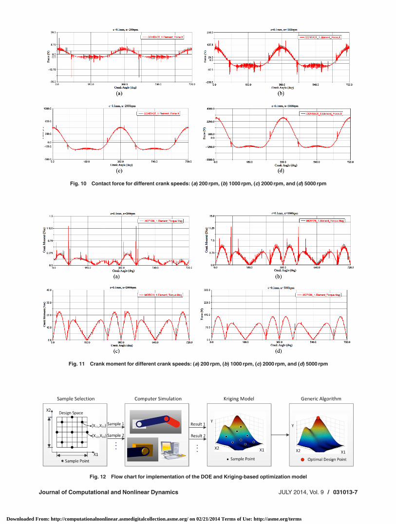
Fig. 10 Contact force for different crank speeds: (a) 200 rpm, (b) 1000 rpm, (c) 2000 rpm, and (d) 5000 rpm
Fig. 11 Crank moment for different crank speeds: (a) 200 rpm, (b) 1000 rpm, (c) 2000 rpm, and (d) 5000 rpm
Fig. 12 Flow chart for implementation of the DOE and Kriging-based optimization model
Journal of Computational and Nonlinear Dynamics JULY 2014, Vol. 9 / 031013-7
Downloaded From: http://computationalnonlinear.asmedigitalcollection.asme.org/ on 02/21/2014 Terms of Use: http://asme.org/terms
The entry correlation matrix for G(x) is given by [16]
Corr G xi; xj
� �� �¼ r2R xi; xj
� �(10)
where R(xi, xj) represents the (i, j) entry of an n� n matrix andthis correlation matrix is defined by the distance between twosample points xi, xj with ones along the diagonal, which can beexpressed as
R xi; xj
� �¼ exp �
Xk
p¼1
hp xpi � xp
j
ap
" #(11)
The term inside the exponential is the distance between the twodesigned sample points (xi, xj), and hp and ap are two parametersthat must be determined in order to make a proper predictionusing the Kriging model. With n sample points (xi, xj), the likeli-hood function of the model parameters can be given as
Likelihood
¼ �1
2n lnð2pÞ þ n ln r2 þ ln Rj j þ 1
2r2y� Alð ÞTR�1 y� Alð Þ
� �(12)
where y is the column vector of the response and A is a n� 1 vec-tor filled with ones. The term l can be estimated as
l ¼ ½ATR�1A��1ATR�1y (13)
The r 2 also can be estimated as [21]
r2 ¼ y� Alð ÞTR�1 y� Alð Þn
(14)
With the preceding two equations, the likelihood function istransformed into a function, which depends only upon the parame-ters hp and ap. In addition, these two parameters can be deter-mined by maximizing the likelihood function and, therefore, thecorrelation matrix R can be calculated. With this predictionmodel, the system performance can be estimated for any givendesign point x* as
Yðx�Þ ¼ lþ rTðx�ÞR�1ðy� AlÞ (15)
where r(x*) is the correlation vector between the prediction pointx* and the design points
x1–xn, which is given by
rT x�ð Þ ¼ Corr G x�; x1ð Þ½ �; :::;Corr G x�; xnð Þ½ �½ � (16)
4.3 Example Use of Kriging Model. In order to explain thesampling method and the Kriging model, a mathematical model,which is shown as the Branin function, is considered in term oftwo variables x1 and x2 as [27]
YðxÞ ¼ x2 �5:1
4p2x2
1 þ5
px1 � 6
�2
þ10 1� 1
8p
�cos x1 þ 1
� �x1 2 ½�5; 10�x2 2 ½0; 15� (17)
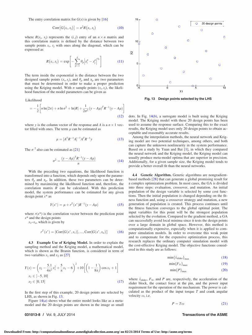
In the first step of this example, 20 design points are selected byLHS, as shown in Fig. 13.
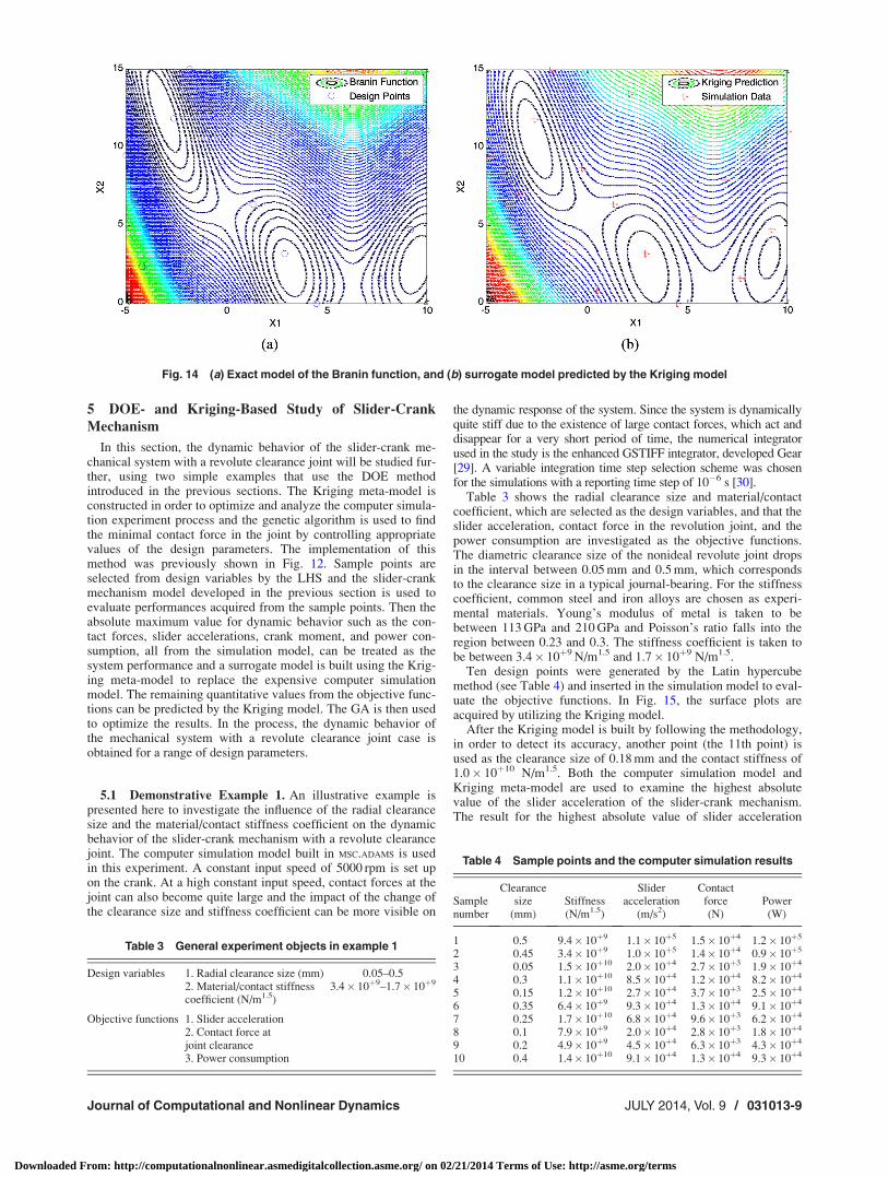
Figure 14(a) shows what the entire model looks like as a meta-model and the 20 design points are shown in the image as small
dots. In Fig. 14(b), a surrogate model is built using the Krigingmodel. The Kriging model with these 20 design points has beenused to assume the response surface. Comparing this to the exactresults, the Kriging model uses only 20 design points to obtain ac-ceptable and reasonably accurate results.
Among the interpolation methods, the neural network and Krig-ing model are two potential techniques, among others, and bothcan capture the unknown nonlinearity in the system performance.Based on a study by Yuan and Bai [1], in which they comparedthe neural network and the Kriging model, the Kriging model canusually produce meta-model optima that are superior in precision.Additionally, for a given sample size, the Kriging model tends toprovide a better overall fit than the neural networks.
4.4 Genetic Algorithm. Genetic algorithms are nongradient-based methods [28] that can generate a global promising result fora complex optimization problem. In most cases, the GA is dividedinto three steps: evaluation, crossover, and mutation. An initialpopulation of the design variable is selected by some cost func-tions. Then the initial population is changed depending on the fit-ness function and, using a crossover strategy and mutation, a newgeneration of population is created. This process continues untilthe fitness function converges to the global optimal point. Theinput variables for this point will be the strongest populationselected by the evolution. Compared to the gradient method, a GAcan successfully avoid local minima since it tests the design pointsover a large domain in global space. However, this method iscomputationally expensive, especially when it is applied to com-puter simulation models. In order to overcome this weak pointand to compensate for the expensive optimization process, thisresearch replaces the ordinary computer simulation model withthe cost-effective Kriging model. The objective functions consid-ered in this study are as follows:
min €xsliderf gmax (18)
min FNf gmax (19)
min Pf gmax (20)
where €xslider, FN, and P are, respectively, the acceleration of theslider block, the contact force at the pin, and the power inputrequirement for the operation of the mechanism. The power is cal-culated as the product of the input torque T and crank angularvelocity x, i.e.
P ¼ Tx (21)
Fig. 13 Design points selected by the LHS
031013-8 / Vol. 9, JULY 2014 Transactions of the ASME
Downloaded From: http://computationalnonlinear.asmedigitalcollection.asme.org/ on 02/21/2014 Terms of Use: http://asme.org/terms
5 DOE- and Kriging-Based Study of Slider-Crank
Mechanism
In this section, the dynamic behavior of the slider-crank me-chanical system with a revolute clearance joint will be studied fur-ther, using two simple examples that use the DOE methodintroduced in the previous sections. The Kriging meta-model isconstructed in order to optimize and analyze the computer simula-tion experiment process and the genetic algorithm is used to findthe minimal contact force in the joint by controlling appropriatevalues of the design parameters. The implementation of thismethod was previously shown in Fig. 12. Sample points areselected from design variables by the LHS and the slider-crankmechanism model developed in the previous section is used toevaluate performances acquired from the sample points. Then theabsolute maximum value for dynamic behavior such as the con-tact forces, slider accelerations, crank moment, and power con-sumption, all from the simulation model, can be treated as thesystem performance and a surrogate model is built using the Krig-ing meta-model to replace the expensive computer simulationmodel. The remaining quantitative values from the objective func-tions can be predicted by the Kriging model. The GA is then usedto optimize the results. In the process, the dynamic behavior ofthe mechanical system with a revolute clearance joint case isobtained for a range of design parameters.
5.1 Demonstrative Example 1. An illustrative example ispresented here to investigate the influence of the radial clearancesize and the material/contact stiffness coefficient on the dynamicbehavior of the slider-crank mechanism with a revolute clearancejoint. The computer simulation model built in MSC.ADAMS is usedin this experiment. A constant input speed of 5000 rpm is set upon the crank. At a high constant input speed, contact forces at thejoint can also become quite large and the impact of the change ofthe clearance size and stiffness coefficient can be more visible on
the dynamic response of the system. Since the system is dynamicallyquite stiff due to the existence of large contact forces, which act anddisappear for a very short period of time, the numerical integratorused in the study is the enhanced GSTIFF integrator, developed Gear[29]. A variable integration time step selection scheme was chosenfor the simulations with a reporting time step of 10�6 s [30].
Table 3 shows the radial clearance size and material/contactcoefficient, which are selected as the design variables, and that theslider acceleration, contact force in the revolution joint, and thepower consumption are investigated as the objective functions.The diametric clearance size of the nonideal revolute joint dropsin the interval between 0.05 mm and 0.5 mm, which correspondsto the clearance size in a typical journal-bearing. For the stiffnesscoefficient, common steel and iron alloys are chosen as experi-mental materials. Young’s modulus of metal is taken to bebetween 113 GPa and 210 GPa and Poisson’s ratio falls into theregion between 0.23 and 0.3. The stiffness coefficient is taken tobe between 3.4� 10þ9 N/m1.5 and 1.7� 10þ9 N/m1.5.
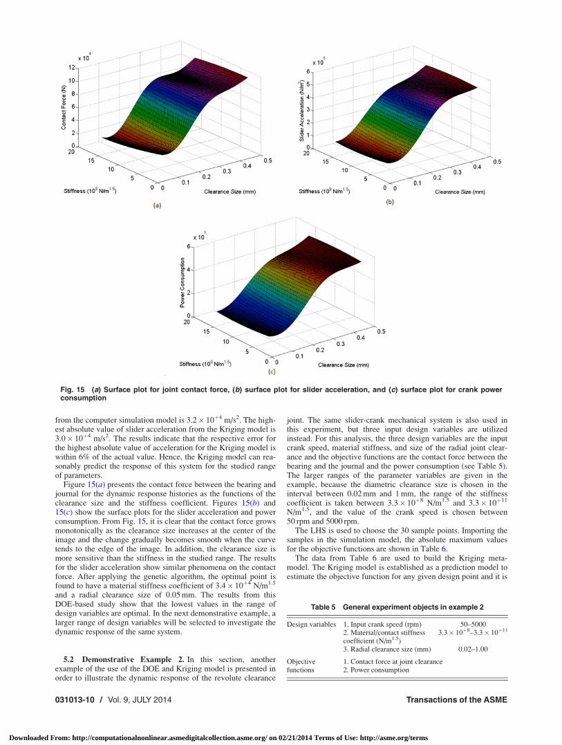
Ten design points were generated by the Latin hypercubemethod (see Table 4) and inserted in the simulation model to eval-uate the objective functions. In Fig. 15, the surface plots areacquired by utilizing the Kriging model.
After the Kriging model is built by following the methodology,in order to detect its accuracy, another point (the 11th point) isused as the clearance size of 0.18 mm and the contact stiffness of1.0� 10þ10 N/m1.5. Both the computer simulation model andKriging meta-model are used to examine the highest absolutevalue of the slider acceleration of the slider-crank mechanism.The result for the highest absolute value of slider acceleration
Fig. 14 (a) Exact model of the Branin function, and (b) surrogate model predicted by the Kriging model
Table 3 General experiment objects in example 1
Design variables 1. Radial clearance size (mm) 0.05–0.52. Material/contact stiffnesscoefficient (N/m1.5)
3.4� 10þ9–1.7� 10þ9
Objective functions 1. Slider acceleration2. Contact force atjoint clearance3. Power consumption
Table 4 Sample points and the computer simulation results
Samplenumber
Clearancesize
(mm)Stiffness(N/m1.5)
Slideracceleration
(m/s2)
Contactforce(N)
Power(W)
1 0.5 9.4� 10þ9 1.1� 10þ5 1.5� 10þ4 1.2� 10þ5
2 0.45 3.4� 10þ9 1.0� 10þ5 1.4� 10þ4 0.9� 10þ5
3 0.05 1.5� 10þ10 2.0� 10þ4 2.7� 10þ3 1.9� 10þ4
4 0.3 1.1� 10þ10 8.5� 10þ4 1.2� 10þ4 8.2� 10þ4
5 0.15 1.2� 10þ10 2.7� 10þ4 3.7� 10þ3 2.5� 10þ4
6 0.35 6.4� 10þ9 9.3� 10þ4 1.3� 10þ4 9.1� 10þ4
7 0.25 1.7� 10þ10 6.8� 10þ4 9.6� 10þ3 6.2� 10þ4
8 0.1 7.9� 10þ9 2.0� 10þ4 2.8� 10þ3 1.8� 10þ4
9 0.2 4.9� 10þ9 4.5� 10þ4 6.3� 10þ3 4.3� 10þ4
10 0.4 1.4� 10þ10 9.1� 10þ4 1.3� 10þ4 9.3� 10þ4
Journal of Computational and Nonlinear Dynamics JULY 2014, Vol. 9 / 031013-9
Downloaded From: http://computationalnonlinear.asmedigitalcollection.asme.org/ on 02/21/2014 Terms of Use: http://asme.org/terms
from the computer simulation model is 3.2� 10þ4 m/s2. The high-est absolute value of slider acceleration from the Kriging model is3.0� 10þ4 m/s2. The results indicate that the respective error forthe highest absolute value of acceleration for the Kriging model iswithin 6% of the actual value. Hence, the Kriging model can rea-sonably predict the response of this system for the studied rangeof parameters.
Figure 15(a) presents the contact force between the bearing andjournal for the dynamic response histories as the functions of theclearance size and the stiffness coefficient. Figures 15(b) and15(c) show the surface plots for the slider acceleration and powerconsumption. From Fig. 15, it is clear that the contact force growsmonotonically as the clearance size increases at the center of theimage and the change gradually becomes smooth when the curvetends to the edge of the image. In addition, the clearance size ismore sensitive than the stiffness in the studied range. The resultsfor the slider acceleration show similar phenomena on the contactforce. After applying the genetic algorithm, the optimal point isfound to have a material stiffness coefficient of 3.4� 10þ4 N/m1.5
and a radial clearance size of 0.05 mm. The results from thisDOE-based study show that the lowest values in the range ofdesign variables are optimal. In the next demonstrative example, alarger range of design variables will be selected to investigate thedynamic response of the same system.
5.2 Demonstrative Example 2. In this section, anotherexample of the use of the DOE and Kriging model is presented inorder to illustrate the dynamic response of the revolute clearance
joint. The same slider-crank mechanical system is also used inthis experiment, but three input design variables are utilizedinstead. For this analysis, the three design variables are the inputcrank speed, material stiffness, and size of the radial joint clear-ance and the objective functions are the contact force between thebearing and the journal and the power consumption (see Table 5).The larger ranges of the parameter variables are given in theexample, because the diametric clearance size is chosen in theinterval between 0.02 mm and 1 mm, the range of the stiffnesscoefficient is taken between 3.3� 10þ8 N/m1.5 and 3.3� 10þ11
N/m1.5, and the value of the crank speed is chosen between50 rpm and 5000 rpm.
The LHS is used to choose the 30 sample points. Importing thesamples in the simulation model, the absolute maximum valuesfor the objective functions are shown in Table 6.
The data from Table 6 are used to build the Kriging meta-model. The Kriging model is established as a prediction model toestimate the objective function for any given design point and it is
Fig. 15 (a) Surface plot for joint contact force, (b) surface plot for slider acceleration, and (c) surface plot for crank powerconsumption
Table 5 General experiment objects in example 2
Design variables 1. Input crank speed (rpm) 50–50002. Material/contact stiffnesscoefficient (N/m1.5)
3.3� 10þ8–3.3� 10þ11
3. Radial clearance size (mm) 0.02–1.00
Objectivefunctions
1. Contact force at joint clearance2. Power consumption
031013-10 / Vol. 9, JULY 2014 Transactions of the ASME
Downloaded From: http://computationalnonlinear.asmedigitalcollection.asme.org/ on 02/21/2014 Terms of Use: http://asme.org/terms
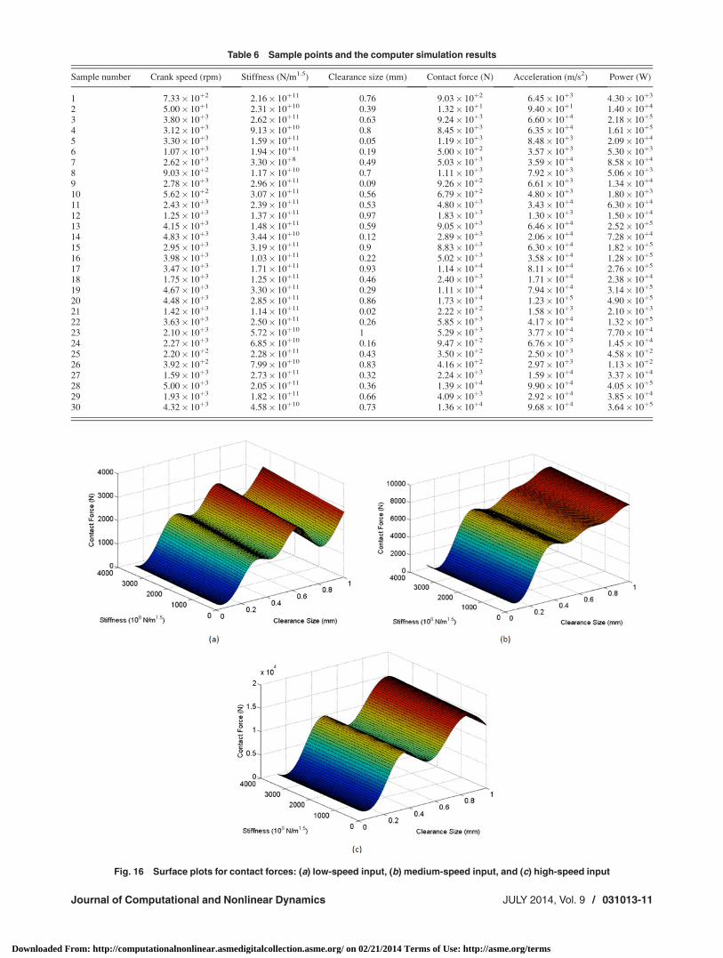
Table 6 Sample points and the computer simulation results
Sample number Crank speed (rpm) Stiffness (N/m1.5) Clearance size (mm) Contact force (N) Acceleration (m/s2) Power (W)
1 7.33� 10þ2 2.16� 10þ11 0.76 9.03� 10þ2 6.45� 10þ3 4.30� 10þ3
2 5.00� 10þ1 2.31� 10þ10 0.39 1.32� 10þ1 9.40� 10þ1 1.40� 10þ4
3 3.80� 10þ3 2.62� 10þ11 0.63 9.24� 10þ3 6.60� 10þ4 2.18� 10þ5
4 3.12� 10þ3 9.13� 10þ10 0.8 8.45� 10þ3 6.35� 10þ4 1.61� 10þ5
5 3.30� 10þ3 1.59� 10þ11 0.05 1.19� 10þ3 8.48� 10þ3 2.09� 10þ4
6 1.07� 10þ3 1.94� 10þ11 0.19 5.00� 10þ2 3.57� 10þ3 5.30� 10þ3
7 2.62� 10þ3 3.30� 10þ8 0.49 5.03� 10þ3 3.59� 10þ4 8.58� 10þ4
8 9.03� 10þ2 1.17� 10þ10 0.7 1.11� 10þ3 7.92� 10þ3 5.06� 10þ3
9 2.78� 10þ3 2.96� 10þ11 0.09 9.26� 10þ2 6.61� 10þ3 1.34� 10þ4
10 5.62� 10þ2 3.07� 10þ11 0.56 6.79� 10þ2 4.80� 10þ3 1.80� 10þ3
11 2.43� 10þ3 2.39� 10þ11 0.53 4.80� 10þ3 3.43� 10þ4 6.30� 10þ4
12 1.25� 10þ3 1.37� 10þ11 0.97 1.83� 10þ3 1.30� 10þ3 1.50� 10þ4
13 4.15� 10þ3 1.48� 10þ11 0.59 9.05� 10þ3 6.46� 10þ4 2.52� 10þ5
14 4.83� 10þ3 3.44� 10þ10 0.12 2.89� 10þ3 2.06� 10þ4 7.28� 10þ4
15 2.95� 10þ3 3.19� 10þ11 0.9 8.83� 10þ3 6.30� 10þ4 1.82� 10þ5
16 3.98� 10þ3 1.03� 10þ11 0.22 5.02� 10þ3 3.58� 10þ4 1.28� 10þ5
17 3.47� 10þ3 1.71� 10þ11 0.93 1.14� 10þ4 8.11� 10þ4 2.76� 10þ5
18 1.75� 10þ3 1.25� 10þ11 0.46 2.40� 10þ3 1.71� 10þ4 2.38� 10þ4
19 4.67� 10þ3 3.30� 10þ11 0.29 1.11� 10þ4 7.94� 10þ4 3.14� 10þ5
20 4.48� 10þ3 2.85� 10þ11 0.86 1.73� 10þ4 1.23� 10þ5 4.90� 10þ5
21 1.42� 10þ3 1.14� 10þ11 0.02 2.22� 10þ2 1.58� 10þ3 2.10� 10þ3
22 3.63� 10þ3 2.50� 10þ11 0.26 5.85� 10þ3 4.17� 10þ4 1.32� 10þ5
23 2.10� 10þ3 5.72� 10þ10 1 5.29� 10þ3 3.77� 10þ4 7.70� 10þ4
24 2.27� 10þ3 6.85� 10þ10 0.16 9.47� 10þ2 6.76� 10þ3 1.45� 10þ4
25 2.20� 10þ2 2.28� 10þ11 0.43 3.50� 10þ2 2.50� 10þ3 4.58� 10þ2
26 3.92� 10þ2 7.99� 10þ10 0.83 4.16� 10þ2 2.97� 10þ3 1.13� 10þ2
27 1.59� 10þ3 2.73� 10þ11 0.32 2.24� 10þ3 1.59� 10þ4 3.37� 10þ4
28 5.00� 10þ3 2.05� 10þ11 0.36 1.39� 10þ4 9.90� 10þ4 4.05� 10þ5
29 1.93� 10þ3 1.82� 10þ11 0.66 4.09� 10þ3 2.92� 10þ4 3.85� 10þ4
30 4.32� 10þ3 4.58� 10þ10 0.73 1.36� 10þ4 9.68� 10þ4 3.64� 10þ5
Fig. 16 Surface plots for contact forces: (a) low-speed input, (b) medium-speed input, and (c) high-speed input
Journal of Computational and Nonlinear Dynamics JULY 2014, Vol. 9 / 031013-11
Downloaded From: http://computationalnonlinear.asmedigitalcollection.asme.org/ on 02/21/2014 Terms of Use: http://asme.org/terms
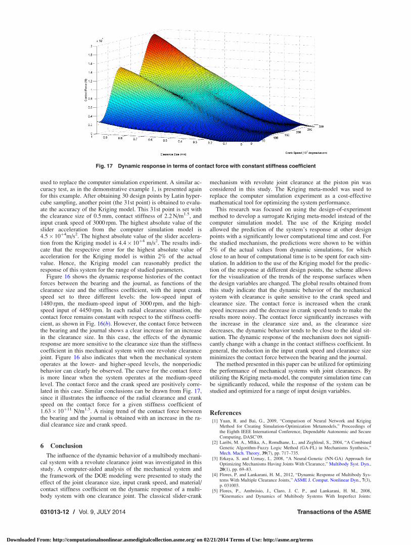
used to replace the computer simulation experiment. A similar ac-curacy test, as in the demonstrative example 1, is presented againfor this example. After obtaining 30 design points by Latin hyper-cube sampling, another point (the 31st point) is obtained to evalu-ate the accuracy of the Kriging model. This 31st point is set withthe clearance size of 0.5 mm, contact stiffness of 2.2 N/m1.5, andinput crank speed of 3000 rpm. The highest absolute value of theslider acceleration from the computer simulation model is4.5� 10þ4m/s2. The highest absolute value of the slider accelera-tion from the Kriging model is 4.4� 10þ4 m/s2. The results indi-cate that the respective error for the highest absolute value ofacceleration for the Kriging model is within 2% of the actualvalue. Hence, the Kriging model can reasonably predict theresponse of this system for the range of studied parameters.
Figure 16 shows the dynamic response histories of the contactforces between the bearing and the journal, as functions of theclearance size and the stiffness coefficient, with the input crankspeed set to three different levels: the low-speed input of1480 rpm, the medium-speed input of 3000 rpm, and the high-speed input of 4450 rpm. In each radial clearance situation, thecontact force remains constant with respect to the stiffness coeffi-cient, as shown in Fig. 16(b). However, the contact force betweenthe bearing and the journal shows a clear increase for an increasein the clearance size. In this case, the effects of the dynamicresponse are more sensitive to the clearance size than the stiffnesscoefficient in this mechanical system with one revolute clearancejoint. Figure 16 also indicates that when the mechanical systemoperates at the lower- and higher-speed levels, the nonperiodicbehavior can clearly be observed. The curve for the contact forceis more linear when the system operates at the medium-speedlevel. The contact force and the crank speed are positively corre-lated in this case. Similar conclusions can be drawn from Fig. 17,since it illustrates the influence of the radial clearance and crankspeed on the contact force for a given stiffness coefficient of1.63� 10þ11 N/m1.5. A rising trend of the contact force betweenthe bearing and the journal is obtained with an increase in the ra-dial clearance size and crank speed.
6 Conclusion
The influence of the dynamic behavior of a multibody mechani-cal system with a revolute clearance joint was investigated in thisstudy. A computer-aided analysis of the mechanical system andthe framework of the DOE modeling were presented to study theeffect of the joint clearance size, input crank speed, and material/contact stiffness coefficient on the dynamic response of a multi-body system with one clearance joint. The classical slider-crank
mechanism with revolute joint clearance at the piston pin wasconsidered in this study. The Kriging meta-model was used toreplace the computer simulation experiment as a cost-effectivemathematical tool for optimizing the system performance.
This research was focused on using the design-of-experimentmethod to develop a surrogate Kriging meta-model instead of thecomputer simulation model. The use of the Kriging modelallowed the prediction of the system’s response at other designpoints with a significantly lower computational time and cost. Forthe studied mechanism, the predictions were shown to be within5% of the actual values from dynamic simulations, for whichclose to an hour of computational time is to be spent for each sim-ulation. In addition to the use of the Kriging model for the predic-tion of the response at different design points, the scheme allowsfor the visualization of the trends of the response surfaces whenthe design variables are changed. The global results obtained fromthis study indicate that the dynamic behavior of the mechanicalsystem with clearance is quite sensitive to the crank speed andclearance size. The contact force is increased when the crankspeed increases and the decrease in crank speed tends to make theresults more noisy. The contact force significantly increases withthe increase in the clearance size and, as the clearance sizedecreases, the dynamic behavior tends to be close to the ideal sit-uation. The dynamic response of the mechanism does not signifi-cantly change with a change in the contact stiffness coefficient. Ingeneral, the reduction in the input crank speed and clearance sizeminimizes the contact force between the bearing and the journal.
The method presented in this paper can be utilized for optimizingthe performance of mechanical systems with joint clearances. Byutilizing the Kriging meta-model, the computer simulation time canbe significantly reduced, while the response of the system can bestudied and optimized for a range of input design variables.
References[1] Yuan, R. and Bai, G., 2009, “Comparison of Neural Network and Kriging
Method for Creating Simulation-Optimization Metamodels,” Proceedings ofthe Eighth IEEE International Conference, Dependable Autonomic and SecureComputing, DASC’09.
[2] Laribi, M. A., Mlika, A., Romdhane, L., and Zeghloul, S., 2004, “A CombinedGenetic Algorithm-Fuzzy Logic Method (GA-FL) in Mechanisms Synthesis,”Mech. Mach. Theory, 39(7), pp. 717–735.
[3] Erkaya, S. and Uzmay, I., 2008, “A Neural-Genetic (NN-GA) Approach forOptimizing Mechanisms Having Joints With Clearance,” Multibody Syst. Dyn.,20(1), pp. 69–83.
[4] Flores, P. and Lankarani, H. M., 2012, “Dynamic Response of Multibody Sys-tems With Multiple Clearance Joints,” ASME J. Comput. Nonlinear Dyn., 7(3),p. 031003.
[5] Flores, P., Ambr�osio, J., Claro, J. C. P., and Lankarani, H. M., 2008,“Kinematics and Dynamics of Multibody Systems With Imperfect Joints:
Fig. 17 Dynamic response in terms of contact force with constant stiffness coefficient
031013-12 / Vol. 9, JULY 2014 Transactions of the ASME
Downloaded From: http://computationalnonlinear.asmedigitalcollection.asme.org/ on 02/21/2014 Terms of Use: http://asme.org/terms
Models and Case Studies,” Lecture Notes in Applied and ComputationalMechanics, Vol. 34, Springer-Verlag, New York.
[6] Haug, E. J. and Huston, R. L., 1985, “Computer Aided Analysis and Optimiza-tion of Mechanical System Dynamics,” ASME J. Appl. Mech., 52(1), pp. 243.
[7] Dubowsky, S., Norris, M., Aloni, E., and Tamir, A., 1984, “An Analytical andExperimental Study of the Prediction of Impacts in Planar Mechanical SystemsWith Clearances,” ASME J. Mech., Transm., Autom. Des., 106(4), pp.444–451.
[8] Dubowsky, S. and Moening, M., 1978, “An Experimental and Analytical Studyof Impact Forces in Elastic Mechanical Systems With Clearances,” Mech.Mach. Theory, 13(4), pp. 451–465.
[9] Furuhashi, T., Morita, N., and Matsuura, M., 1977, “Dynamic Researches ofFour-Bar Linkage With Clearance at Turning Pairs: 4th Report, Forces Actingat Joints of Crank-Lever Mechanism,” Trans. Jpn. Soc. Mech. Eng., 43(376),pp. 4644–4651.
[10] Lankarani, H. M. and Nikravesh, P. E., 1990, “A Contact Force Model WithHysteresis Damping for Impact Analysis of Multibody Systems,” ASME J.Mech. Des., 112(3), pp. 369–376.
[11] Flores, P., Ambrosio, J., Claro, J. C. P., Lankarani, H. M., and Koshy, C., 2006,“A Study on Dynamics of Mechanical Systems Including Joints With Clearanceand Lubrication,” Mech. Mach. Theory, 41(3), pp. 247–261.
[12] Flores, P., Lankarani, H. M., Ambr�osio, J., and Claro, J. C. P., 2004,“Modelling Lubricated Revolute Joints in Multibody Mechanical Systems,”Proc. Inst. Mech. Eng., Part K, 218(4), pp. 183–190.
[13] Flores, P. and Lankarani, H. M., 2010, “Spatial Rigid-Multi-Body SystemsWith Lubricated Spherical Clearance Joints: Modeling and Simulation,” Non-linear Dyn., 60(1–2), pp. 99–114.
[14] Mahrus, D., 1974, “Experimental Investigation Into Journal Bearing Perform-ance,” Rev. Bras. Tecnol., 5(3–4), pp. 139–152.
[15] Wilson, R. and Fawcett, J. N., 1974, “Dynamics of Slider-Crank MechanismWith Clearance in the Sliding Bearing,” Mech. Mach. Theory, 9(1), p. 61–80.
[16] Haines, R. S., 1980, “A Theory of Contact Loss at Resolute Joints With Clearance,”Proc. Inst. Mech. Eng., Part C: J. Mech. Eng. Sci., 22(3), pp. 129–136.
[17] Flores, P., Ambr�osio, J., Claro, J. C. P., and Lankarani, H. M., 2007, “DynamicBehaviour of Planar Rigid Multi-Body Systems including Revolute Joints WithClearance,” Proc. Inst. Mech. Eng., Part K, 221(2), pp. 161–174.
[18] Bengisu, M. T., Midayetoglu, T., and Akay, A., 1986, “A Theoretical and Ex-perimental Investigation of Contact Loss in the Clearances of a Four-Bar Mech-anism,” ASME J. Mech., Transm., Autom. Des., 108, pp. 237–244.
[19] Feng, B., Morita, N., and Torii, T., 2002, “A New Optimization Method forDynamic Design of Planar Linkage With Clearances at Joints—Optimizing theMass Distribution of Links to Reduce the Change of Joint Forces,” ASME J.Mech. Des., 124(1), pp. 68–73.
[20] Tsai, M. and Lai, T., 2004, “Kinematic Sensitivity Analysis of Linkage WithJoint Clearance Based on Transmission Quality,” Mech. Mach. Theory, 39(11),pp. 1189–1206.
[21] Yildirim, S., Erkaya, S., Su, S., and Uzmay, I., 2005, “Design of Neural Net-works Model for Transmission Angle of a Modified Mechanism,” J. Mech. Sci.Technol., 19(10), pp. 1875–1884.
[22] Flores, P., Koshy, C. S., Lankarani, H. M., Ambr�osio, J., and Claro, J. C. P.,2011, “Numerical and Experimental Investigation on Multibody Systems WithRevolute Clearance Joints,” Nonlinear Dyn., 65(4), pp. 383–398.
[23] Hirsa, A., 2011, Computational Methods in Finance, CRC, Boca Raton, FL, pp.224–228.
[24] Simpson, T. W., Mauery, T. M., Korte, J. J., and Mistree, F., 1998, “Comparisonof Response Surface and Kriging Models for Multidisciplinary Design Opti-mization,” Proceedings of the 7th AIAA/USAF/NASA/ISSMO Symposium onMultidisciplinary Analysis and Optimization, AIAA Paper No. 98–4758.
[25] Kbiob, D. G., 1951, “A Statistical Approach to Some Basic Mine Valuation Prob-lems on the Witwatersrand,” J. Chem. Metall. Min. Soc. S. Afr., 52, pp. 119–139.
[26] Cressie, N., 1990, “The Origins of Kriging,” Math. Geol., 22(3), pp. 239–252.[27] Forrester, A., Sobester, A., and Keane, A., 2008, Engineering Design Via Sur-
rogate Modeling: A Practical Guide, Wiley, New York.[28] Goldberg, D. E., 1985, Genetic Algorithms in Search, Optimization, and
Machine Learning, Addison-Wesley, Reading, MA.[29] Gear, C. W., Leimkuhler, B., and Gupta, G. K., 1985, “Automatic Integration
of Euler-Lagrange Equations With Constraints,” J. Comput. Appl. Math., 12,pp. 77–90.
[30] Flores, P., Machado, M., Seabra, E., and Silva, M. T., 2011, “A ParametricStudy on the Baumgarte Stabilization Method for Forward Dynamics of Con-strained Multibody Systems,” ASME J. Comput. Nonlinear Dyn., Vol 6(1),p. 011019.
Journal of Computational and Nonlinear Dynamics JULY 2014, Vol. 9 / 031013-13
Downloaded From: http://computationalnonlinear.asmedigitalcollection.asme.org/ on 02/21/2014 Terms of Use: http://asme.org/terms