Embed Size (px)
Citation preview
Regulatory informationSupplier: UTC Fire & Security Americas Corporation, Inc.1275 Red Fox Rd., Arden Hills, MN 55112-6943,USAAuthorized EU supplier representative: UTC Fire & Security B.V. Kelvinstraat 7, 6003 DH Weert, NetherlandsWeee Directive: 2002/96/EC (WEEE directive): Products marked with
this symbol cannot be disposed of as unsorted municipal waste in the European Union. For proper recycling, return this product to your local supplier upon the purchase of equivalent new equipment, or dispose of it at designated collection points. For more information see: www.recyclethis.info.
RoHs Directive: 2002/95/EC RoHS Compliant. Hereby, UTC Fire and Security declares that this device does not contain lead, mercury, cadmium, hexavalent chromium, polybrominated biphenyls (PBB) or polybrominated depheny ethers (PBDE) in more than the percentage specified by EU directive 2002/95/EC, except exemptions stated in EUdirective 2002/95/EC annex.CE Directive: 2004/108/EC (CE directive): Hereby, UTC Fire & Security
declares that this device is in compliance with the essential requirements and other relevant provisions of Directive 2004/108/EC.
FCC Statement: Complies with FCC Part 15 Class B.Maintenance: Test yearly by the installerWarranty: 5 year replacement warrantySecurity grade: EN Grade 2 (Llarmklass 3)Environmental class: Class IIStandards: EN50131-2-2The 6540, 6540PI and 6550 have been tested and certified to EN50131-2-2 for Security Grade 2, environmental class II, by the Dutch testingand certification body Telefication B.V.Disclaimer: The 6540/6540U, 6550/6550U, 6540PI/6540UPI is not a complete alarm system, but only its part. Therefore UTC Fire & Security does not accept any responsibility or liability for any damage that is claimed to be a result of an incorrect functioning of the 6540/6540U, 6550/6550U, 6540PI/6540UPI detector. UTC Fire & Security reserves the right to change the specification without a prior notice.
Installation Sheet 6540 - 6540PI - 6550 PIR
UL/CUL: 6540U - 6540UPI - 6550U PIR
EN ES FR IT NL PL PT SV
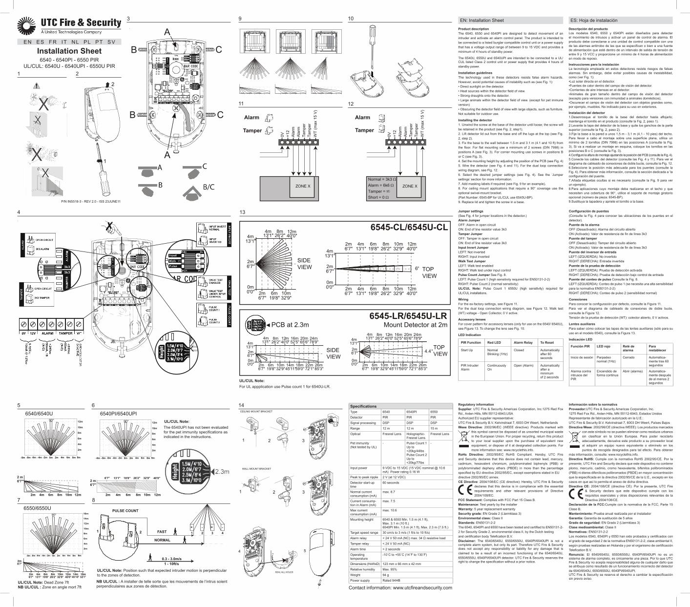
Product descriptionThe 6540, 6550 and 6540PI are designed to detect movement of an intruder and activate an alarm control panel. The product is intended to be connected to a listed burglar compatible control unit or a power supply that has a voltage output range of between 9 to 15 VDC and provides a minimum of 4 hours of standby power.
The 6540U, 6550U and 6540UPI are intended to be connected to a UL/CUL listed Class 2 control unit or power supply that provides 4 hours of standby power.
Installation guidelinesThe technology used in these detectors resists false alarm hazards. However, avoid potential causes of instability such as (see Fig. 1):• Direct sunlight on the detector.• Heat sources within the detector field of view.• Strong draughts onto the detector.• Large animals within the detector field of view. (except for pet immune version)• Obscuring the detector field of view with large objects, such as furniture.Not suitable for outdoor use.
Installing the detector1. Unwind the screw at the base of the detector until loose; the screw will be retained in the product (see Fig. 2, step1).2. Lift detector lid out from the base and off the lugs at the top (see Fig. 2, step 2).3. Fix the base to the wall between 1.5 m and 3.1 m (4.1 and 10 ft) from the floor. For flat mounting use a minimum of 2 screws (DIN 7998) in positions A (see Fig. 3). For corner mounting use screws in positions B or C (see Fig. 3).4. Set the mounting height by adjusting the position of the PCB (see Fig. 4)5. Wire the detector (see Fig. 4 and 11). For the dual loop connection wiring diagram, see Fig. 12.6. Select the desired jumper settings (see Fig. 4). See the ‘Jumper settings’ section for more information.7. Add masking labels if required (see Fig. 9 for an example).8. For ceiling mount applications that require a 90° coverage use the optional swivel-mount bracket.(Part Number: 6545-BP for UL/CUL use 6545U-BP).9. Replace lid and tighten the screw in a base.
Contact information: www.utcfireandsecurity.com
6545-CL/6545U-CL
SIDE VIEW 6° TOP
VIEW
12m40'0"
2m6'7"
0m0'0"
4m13'1"
12m40'0"
6m19'8"
4m13'1"
10m32'9"
8m26'2"
2m6'7"6m
19'8"10m32'9"
2m6'7"
4m13'1"
8m26'2"
2m6'7"
0m0'0"
SIDE VIEW
2m6'7"
4m13'1"
0m0'0"
12m40'0"
16m52'5"
20m65'6"
24m78'9"
6m19'8"
4m13'1"
10m32'9"
14m45'11"
18m59'0"
22m72'1"
26m85'3"
8m26'2"
2m6'7"
TOP VIEW4.4°2m
6'7"
4m13'1"
0m0'0"
12m40'0"
16m52'5"
20m65'6"
24m78'9"
6m19'8"
4m13'1"
10m32'9"
14m45'11"
18m59'0"
22m72'1"
26m85'3"
8m26'2"
2m6'7"
6545-LR/6545U-LRPCB at 2.3m Mount Detector at 2m
4m13'1"
12m40'0"
6m19'8"
4m13'1"
10m32'9"
8m26'2"
2m6'7"
Not pet immune (PI)
ZONE X
0V +12
Ala
rmA
larm
Tam
per
Tam
per
WT
(max
15
V)
Alarm
Tamper
Normal = 3k3 ΩAlarm = 6k6 Ω
∞Short = 0 Ω
ZONE X
0V +12
Ala
rmA
larm
Tam
per
Tam
per
WT
(max
15
V)
Alarm
Tamper
Tamper =
A
B C
CB
A
1
2
Not used. J2: LED on.
LED off.
J5:
J6:
6540/6540U
2m
4m
6m
8m
10m
12m
0m 2m 4m 6m 8m-2m-4m-6m-8m-9m 9m
90°
2 m
6m4m 10m8m2m
6'7"6'7" 13'1" 19'8" 26'2" 32'9" 40'0"
6540PI/6540UPI
2m
4m
6m
8m
10m
12m
0m 2m 4m 6m 8m-2m-4m-6m-8m-9m 9m
90°
12m6m4m 10m8m2m
2 m6'7"
6550/6550U
0m 2m 4m 6m 8m-2m-4m-6m-8m-9m
90°
+ +- -1 2 3 4
0.3 - 3.0m/s
PULSE COUNT
1 2
1 - 10ft/s
FAST
NORMAL
SpecificationsType 6540 6540PI 6550
Detector PIR PIR PIR
Signal processing DSP DSP DSP
Range 12 m 12 m 15 m
Optical Fresnel Lens Holographic-Fresnel Lens
Fresnel Lens
Pet immunity(Not tested by UL)
- Pulse Count 1 Up to <20kg/44lbsPulse Count 2 Up to <35kg/77lbs
-
Input power 9 VDC to 15 VDC (15 VDC nominal @ 10.6 mA) Power rating 0.16 W
Peak to peak ripple 2 V (at 12 VDC)
Detector start-up time
60 seconds
Normal current consumption (mA)
max. 8.7
Current consump-tion in Alarm (mA)
max. 7.5
Max current consumption (mA)
max. 10.6
Mounting height 6540 & 6550 Min. 1.5 m (4.1 ft), Max. 3.1 m (10 ft.) 6540PI Min. 1.5 m (4.1 ft), Max. 2.3 m (7.5 ft.)
Target speed range 30 cm/s to 3 m/s (1 ft/s to 10 ft/s)
Alarm relay < 24 V 50 mA (NC) max. 34 Ω resistive load
Tamper relay < 24 V 50 mA (NC)
Alarm time > 2 seconds
Operating temperature
-10˚C to +55˚C (14˚F to 130˚F)
Dimensions (HxWxD) 123 mm x 66 mm x 42 mm
Relative humidity Max. 95%
Weight 94 g
Power supply Rated 94HB
EN: Installation Sheet ES: Hoja de instalación
Descripción del productoLos modelos 6540, 6550 y 6540PI están diseñados para detectar el movimiento de intrusos y activar un panel de control de alarma. El producto debe conectarse a una unidad de control compatible con una de las alarmas antirrobo de las que se especifican o bien a una fuente de alimentación que esté dentro de un intervalo de salida de tensión de entre 9 y 15 VCC y proporcione un mínimo de 4 horas de alimentación en modo de reposo.
Instrucciones para la instalaciónLa tecnología empleada en estos detectores resiste riesgos de falsas alarmas. Sin embargo, debe evitar posibles causas de inestabilidad, como (ver Fig. 1):•Luz solar directa en el detector.•Fuentes de calor dentro del campo de visión del detector.•Corrientes de aire intensas en el detector.•Animales de gran tamaño dentro del campo de visión del detector (excepto para versiones con inmunidad a animales domésticos).•Oscurecer el campo de visión del detector con objetos grandes como, por ejemplo, muebles. No indicado para su uso en exteriores.
Instalación del detector1.Desenrosque el tornillo de la base del detector hasta aflojarlo; mantenga el tornillo en el producto (consulte la Fig. 2, paso 1).2.Levante la tapa del detector de la base y quite los ganchos de la parte superior (consulte la Fig. 2, paso 2).3.Fije la base a la pared a unos 1,5 m - 3,1 m (4,1 - 10 pies) del techo. Para llevar a cabo el montaje sobre una superficie plana, utilice un mínimo de 2 tornillos (DIN 7998) en las posiciones A (consulte la Fig. 3). Si va a realizar un montaje en esquina, coloque los tornillos en las posiciones B o C (consulte la Fig. 3).4.Configure la altura de montaje ajustando la posición del PCB (consulte la Fig. 4).5.Conecte los cables del detector (consulte las Fig. 4 y 11). Para ver el diagrama de cableado de conexiones de doble bucle, consulte la Fig. 12.6.Seleccione la posición más adecuada para los puentes (consulte la Fig. 4). Para obtener más información, consulte la sección dedicada a ‘la configuración del puente.7.Añada etiquetas ocultas si es necesario (consulte la Fig. 9 para ver un ejemplo).8.Para aplicaciones cuyo montaje deba realizarse en el techo y que necesiten una cobertura de 90°, utilice el soporte de montaje giratorio opcional (número de pieza: 6545-BP).9.Sustituya la tapadera y apriete el tornillo a la base.
1
3
Not pet immune (PI)
2
4
5 6
7 8
13
9
11 12
14
10
A
B C
CB
A
A
B C
CB
A
Jumper settings(See Fig. 4 for jumper locations in the detector.)Alarm JumperOFF: Alarm in open circuit ON: End of line resistor value 3k3Tamper JumperOFF: Tamper in open circuit ON: End of line resistor value 3k3Input Invert JumperLEFT: Not inverted RIGHT: Input invertedWalk Test JumperLEFT: Walk test enabled RIGHT: Walk test under input controlPulse Count Jumper See Fig. 8.LEFT: Pulse Count 1 (high sensitivity required for EN50131-2-2)RIGHT: Pulse Count 2 (normal sensitivity) UL/CUL Note: Pulse Count 1 6550U (high sensitivity) required for UL/CUL installations.
WiringFor the ex-factory settings, see Figure 11.For the dual loop connection wiring diagram, see Figure 12. Walk test (WT) voltage - Open Collector, 0 V active.
Accessory lensesFor cover pattern for accessory lenses (only for use on the 6540/ 6540U), see Figure 13. To change the lens see Fig. 10.
LED Indication
PIR Function Red LED Alarm Relay To Reset
Start Up NormalBlinking (1Hz)
Closed Automaticallyafter 60 seconds
PIR IntruderAlarm
ContinuouslyOn
Open (Alarm) Automaticallyafter a minimumof 2 seconds
Configuración de puentes (Consulte la Fig. 4 para conocer las ubicaciones de los puentes en el detector).Puente de la alarmaOFF (Desactivado): Alarma del circuito abiertoON (Activado): Valor de resistencia de fin de línea 3k3Puente del tamperOFF (Desactivado): Tamper del circuito abiertoON (Activado): Valor de resistencia de fin de línea 3k3Puente del inversor de entradaLEFT (IZQUIERDA): No invertidoRIGHT (DERECHA): Entrada invertidaPuente de la prueba de detecciónLEFT (IZQUIERDA): Prueba de detección activadaRIGHT (DERECHA): Prueba de detección bajo control de entradaPuente del conteo de pulso Consulte la Fig. 8.LEFT (IZQUIERDA): Conteo de pulso 1 (se necesita una alta sensibilidad para la normativa EN50131-2-2)RIGHT (DERECHA): Conteo de pulso 2 (sensibilidad normal)
ConexionesPara conocer la configuración por defecto, consulte la Figura 11.Para ver el diagrama de cableado de conexiones de doble bucle, consulte la Figura 12.Tensión de la prueba de detección (WT): colector abierto, 0 V activos.
Lentes auxiliaresPara saber cómo colocar las tapas de las lentes auxiliares (sólo para su uso en el modelo 6540), consulte la Figura 13.
Indicación LED
Función PIR LED rojo Relé de alarma
Para restablecer
Inicio de sesión Parpadeo normal (1Hz)
Cerrado Automática-mente tras 60 segundos
Alarma contra intrusos del PIR
Encendido de forma continua
Abrir (alarma) Automática-mente después de al menos 2 segundos
Información sobre la normativaProveedor:UTC Fire & Security Americas Corporation, Inc.1275 Red Fox Rd., Arden Hills, MN 55112-6943, Estados UnidosRepresentante de fabricación autorizado en la U.E.:UTC Fire & Security B.V. Kelvinstraat 7, 6003 DH Weert, Países BajosDirectiva Weee: 2002/96/CE (directiva WEEE): Los productos marcados
con este símbolo no se pueden eliminar como residuos urbanos sin clasificar en la Unión Europea. Para poder reciclarlo adecuadamente, devuelva este producto a su proveedor local al adquirir un equipo nuevo equivalente o elimínelo en los puntos de recogida designados para tal efecto. Para obtener
más información, consulte: www.recyclethis.info.Directiva RoHS: Cumple con la normativa RoHS 2002/95/CE. Por la presente, UTC Fire and Security declara que este dispositivo no contiene plomo, mercurio, cadmio, cromo hexavalente, bifenilos polibrominados (PBB) ni éteres difenílicos polibromados (PBDE) en mayor concentración que la especificada en la directiva 2002/95/CE de la U.E., excepto en los casos en que así lo permita el anexo de dicha directiva.Directiva CE: 2004/108/CE (directiva CE): Por la presente, UTC Fire
& Security declara que este dispositivo cumple con los requisitos esenciales y otras disposiciones relevantes de la Directiva 2004/108/CE.
Declaración de la FCC:Cumple con la normativa de la FCC, Parte 15 Clase B.Mantenimiento: Prueba anual realizada por el instaladorGarantía: Garantía de sustitución de 5 añosGrado de seguridad: EN Grado 2 (Llarmklass 3)Clase medioambiental: Clase IINormativas: EN50131-2-2Los modelos 6540, 6540PI y 6550 han sido probados y certificados con el grado de seguridad 2 de la normativa EN50131-2-2, clase ambiental II, según pruebas realizadas en Holanda y por el organismo de certificación Telefication B.V.Renuncia: El 6540/6540U, 6550/6550U, 6540PI/6540UPI no es un sistema de alarma completo, es únicamente una pieza. Por lo que UTC Fire & Security no acepta responsabilidad alguna de cualquier daño que se atribuya como resultado de un funcionamiento incorrecto del detector de 6540/6540U, 6550/6550U, 6540PI/6540UPI.UTC Fire & Security se reserva el derecho a cambiar la especificación sin previo aviso.
UL/CUL Note: Position such that expected intruder motion is perpendicular to the zones of detection.
P/N INS518-3 - REV 2.0 - ISS 23JUNE11
UL/CUL Note:The 6540UPI has not been evaluated for the pet immunity specifications as indicated in the instructions.
NB UL/CUL : A installer de telle sorte que les mouvements de l’intrus soient perpendiculaires aux zones de détection.
UL/CUL Note: Dead Zone 7ftNB UL/CUL : Zone en angle mort 7ft
UL/CUL Note:For UL appplication use Pulse count 1 for 6540U-LR.

RegelgevingLeverancier: UTC Fire & Security Americas Corporation, Inc.1275 Red Fox Rd., Arden Hills, MN 55112-6943, USAGeautoriseerde EU-vertegenwoordiger:UTC Fire & Security B.V. Kelvinstraat 7, 6003 DH Weert, NederlandWeee-richtlijn: 2002/96/EC (WEEE-richtlijn): Producten met dit
symbool mogen in de Europese Unie niet bij het ongesorteerde gemeenteafval worden gegooid. Voor een correcte recycling dient u dit product te retourneren aan uw lokale leverancier op het moment dat u een vergelijkbaar nieuw product aanschaft, of het weg te gooien op toegewezen verzamelpunten. Voor meer
informatie zie: www.recyclethis.info.RoHs-richtlijn: 2002/95/EC RoHS-richtlijn. Hierbij verklaart UTC Fire and Security dat dit apparaat geen lood, kwik, cadmium, hexavalent chroom, polybroombifenyl (PBB) of polygebromeerde difenylether (PBDE) bevat in hogere percentages dan is vermeld in EU-richtlijn 2002/95/EC, uitgezonderd vrijstellingen in EU-richtlijn 2002/95/EC annex.CE-richtlijn: 2004/108/EC (CE-richtlijn): Hierbij verklaart UTC Fire
& Security dat dit apparaat voldoet aan de noodzakelijke vereisten en andere relevante voorzieningen van richtlijn 2004/108/EC.
FCC-verklaring: Voldoet aan FCC Part 15 klasse B.Onderhoud: Jaarlijkse test door installateurGarantie: 5 jaar vervangende garantieBeveiligingsniveau: EN klasse 2 (Llarmklass 3)Milieuklasse: Klasse IIStandaarden: EN 50131-2-2De 6540, 6540PI en 6550 zijn getest en gecertificeerd op EN50131-2-2 voor beveiligingsniveau 2, milieuklasse II, door het Nederlandse test- en certificeringsorgaan Telefication B.V.Disclaimer: De 6540/6540U, 6550/6550U, 6540PI/6540UPI is geen volledig alarmsysteem, maar vormt slechts een onderdeel daarvan. Daarom kan UTC Fire & Security niet aansprakelijk worden gehouden voor enige schade die wordt geclaimd als gevolg van het onjuist functioneren van de 6540/6540U, 6550/6550U, 6540PI/6540UPI PIR-detector.UTC Fire & Security behoudt het recht voor om de specificaties zonder voorafgaande kennisgeving te wijzigen.
Informazioni sulle normativeFornitore: UTC Fire & Security Americas Corporation, Inc.1275 Red Fox Rd., Arden Hills, MN 55112-6943, USARappresentante autorizzato per l’UE:UTC Fire & Security B.V. Kelvinstraat 7, 6003 DH Weert, Paesi BassiDirettiva WEEE: 2002/96/CE (direttiva WEEE): all’interno dell’Unione
europea i prodotti contrassegnati con questo simbolo non possono essere smaltiti come normali rifiuti. Al momento dell’acquisto di un’apparecchiatura nuova analoga restituire il prodotto al fornitore locale o smaltirlo consegnandolo presso gli appositi punti di raccolta. Per ulteriori informazioni vedere: www.
recyclethis.info.Direttiva RoHS: Conforme alla direttiva 2002/95/EC (RoHS), UTC Fire e Security dichiara che il presente dispositivo non contiene piombo, mercurio, cadmio, cromo esavalente, bifenili polibromurati (PBB) o etere di difenile polibrominato (PBDE) in una percentuale superiore a quella specificata dalla direttiva dell’Unione Europea 2002/95/EC, eccetto per le estensioni indicate nell’allegato alla direttiva dell’Unione Europea 2002/95/EC.Direttiva CE: 2004/108/CE (direttiva CE): UTC Fire & Security dichiara
che il presente dispositivo è conforme con i requisiti essenziali e altre disposizioni relative della direttiva 2004/108/CE.
Dichiarazione di conformità FCC: Conforme alle norme FCC parte 15 classe B.Manutenzione: Eseguire una manutenzione annuale da parte dell’installatoreGaranzia: Garanzia di sostituzione di 5 anniLivello di sicurezza: EN grado 2 (Larmklass 3)Classe ambientale: Classe IIStandard: EN 50131-2-2I rilevatori 6540, 6540PI e 6550 sono stati approvati dall’organismo olandese di test e certificazione Telefication B.V per gli standard EN 50131-2-2 per il livello di sicurezza 2, classe ambientale II.Esonero dalle responsabilità: Il rilevatore 6540/6540U, 6550/6550U, 6540PI/6540UPI non costituisce un sistema di allarme completo, ma solo una parte di esso. UTC Fire & Security non si assume pertanto alcuna responsabilità per eventuali danni che vengano dichiarati essere derivanti dal funzionamento non corretto del rilevatore PIR 6540/6540U, 6550/6550U, 6540PI/6540UPI. UTC Fire & Security si riserva il diritto di modificare le specifiche senza preavviso.
FR: Fiche d’installation IT: Foglio di installazione NL: Installatie instructies PL: Instrukcja instalacji PT: Ficha de Instalação SV: Installationsmanual
Description du produitLes détecteurs 6540, 6550 et 6540PI sont conçus pour détecter le déplacement d’un intrus et activer une centrale d’alarme. Il est prévu que l’appareil soit connecté à une unité d’alimentation ou une unité de commande répertoriée compatible avec un système intrusion présentant une tension d’alimentation entre 9 et 15 Vcc et fournissant au moins 4 heures de courant en veille.La gamme de détecteurs 6540U/6540UPI/6550U - est destinée à être connectée à une centrale approuvée UL / CUL ou à une alimentation indépendante qui offre 4 heures d’autonomie.Instructions d’installationLa technologie utilisée dans ces détecteurs est conçue pour résister aux risques de fausses alarmes. Toutefois, il est conseillé d’éviter les causes d’instabilité potentielles, telles que (voir figure 1) :•L’exposition du détecteur à la lumière directe du soleil.•Les sources de chaleur dans le champ de vision du détecteur.•Les courants d’air puissants sur le détecteur.•La présence de grands animaux dans le champ de couverture du détecteur. (hormis le modèle insensible aux animaux domestiques)•L’obstruction du champ de couverture du détecteur par des objets volumineux, comme des meubles. •Ne convient pas à une installation extérieure.Installation du détecteur1.Desserrez la vis à la base du détecteur jusqu’à ce qu’il se décroche. La vis reste logée dans l’appareil (voir figure 2, étape 1).2.Soulevez le couvercle du détecteur de la base et dégager le des 2 ergots du haut (voir figure 2, étape 2).3.Fixez la base sur le mur à une hauteur variant de 1,5 à 3,1m du sol. Pour un montage à plat, utilisez au moins 2 vis (DIN 7998) dans les positions A (voir figure 3). Pour un montage dans un angle, utilisez des vis dans les positions B ou C (voir figure 3).4.Réglez la hauteur de montage en ajustant la position de la platine (voir la figure 4) puis serrez la vis.5.Raccordez le détecteur (voir figures 4 et 11). Pour connaître le schéma de câblage pour une connexion en boucle double, reportez-vous à la Fig. 12.6.Réglez les cavaliers de manière appropriée (voir figure 4). Pour plus d’informations, consultez la section Réglage du cavalier.7.Ajoutez, si nécessaire, des étiquettes de masquage (pour un exemple, voir figure 9).8.Pour les applications à montage au plafond nécessitant une couverture de 90 °, utilisez la patte de fixation à pivot en option (numéro de série : 6545-BP).9.Replacez le couvercle et serrez la vis dans une base.
Descrizione del prodottoI rilevatori 6540, 6550 e 6540PI sono progettati per individuare il movimento di eventuali intrusi e attivare una centrale di allarme.
Linee guida per l’installazioneLa tecnologia utilizzata per questi rivelatori è a prova di falsi allarmi. È tuttavia necessario evitare potenziali cause di instabilità, quali (vedere la fig. 1):•Esposizione del rilevatore alla luce solare diretta.•Fonti di calore nel campo visivo del rivelatore.•Forti correnti d’aria in prossimità del rilevatore.•Animali di grosse dimensioni nel campo visivo del rivelatore (eccetto per la versione che prevede la presenza di animali domestici).•Oscuramento del campo visivo del rilevatore con oggetti di grandi dimensioni (es. mobilio). Non adatto per l’utilizzo all’esterno.
Installazione del rivelatore1.Allentare la vite alla base del rilevatore, in modo che rimanga all’interno del prodotto (vedere la fig. 2, passo 1)2.Sollevare il coperchio del rilevatore dalla base e rimuoverlo dagli innesti in alto (vedere la fig. 2, passo 2)3.Fissare la base al muro a un’altezza dal pavimento compresa tra 1,5 e 3,1 m. Per il montaggio su superficie piana utilizzare almeno due viti (DIN 7998) nelle posizioni A (vedere la fig. 3). Per il montaggio ad angolo utilizzare le viti nelle posizioni B o C (vedere fig. 3)4.Impostare l’altezza di montaggio regolando la posizione della PCB (vedere la fig. 4)5.Collegare il rilevatore (vedere fig. 4 e 11). Per lo schema di collegamento con doppio bilanciamento, vedere la fig. 126.Selezionare le impostazioni dei ponticelli desiderate (vedere fig. 4). Per ulteriori informazioni, vedere la sezione Impostazioni dei ponticelli.7.Se necessario, aggiungere delle etichette per il mascheramento (vedere la fig. 9 per un esempio)8 Per applicazioni con montaggio a soffitto che richiedano una copertura a 90°, utilizzare il supporto mobile opzionale (Numero parte: 6545-BP)9.Riposizionare il coperchio e serrare la vite alla base.
ProductbeschrijvingDe 6540, 6550 en 6540PI zijn ontworpen om de bewegingen te detecteren van een indringer en een alarmcentrale te activeren. Het product moet worden aangesloten op een centrale die compatibel is met een geregistreerd inbraakalarmsysteem, of een voedingseenheid die een spanning levert tussen 9 en 15 VDC, alsmede minimaal 4 uur stand-by voeding.
Richtlijnen voor de installatieDe technologie in deze detector is bestand tegen de gevaren van valse alarmen. Vermijd niettemin alle mogelijke oorzaken van instabiliteit, zoals (zie afbeelding 1):•Rechtstreeks zonlicht op de detector.•Hittebronnen in het detectieveld.•Veel tocht op de detector.•Grote dieren in het detectieveld. (behalve de versie ongevoelig voor huisdieren) •Het kijkveld van de detector versperren met grote objecten, zoals meubels.Niet geschikt voor buitengebruik.
De detector installeren1.Draai de schroef aan de basis van de detector los; de schroef blijft aan het product vastzitten (zie afbeelding 2, stap 1)2.Til het deksel van de detector uit de basisen van de aansluitpunten aan de andere bovenkant (zie afbeelding 2, step 2)3.Bevestig de basis aan de wand tussen 1,5 m en 3,1 m van de vloer. Gebruik voor een vlakke montage ten minste 2 schroeven (DIN 7998) in de posities A (zie afbeelding 3). Gebruik voor hoekmontage de schroeven in posities B of C (zie afbeelding 3)4.Stel de montagehoogte in door de positie van de PCB aan te passen (zie afbeelding 4)5.Sluit de bedrading van de detector aan (zie afbeeldingen 4 en 11). Zie afbeelding 12 voor het bedradingsschema van de dubbele lusaansluiting.6.Selecteer de gewenste jumperinstellingen (zie afbeelding 4). Zie de sectie ‘Jumperinstellingen’ voor meer informatie.7.Voeg eventueel maskeringslabels toe (zie bijvoorbeeld afbeelding 9)8.Als u de detector aan het plafond wilt bevestigen voor een 90° dekking, moet u de optionele zwenkbeugel gebruiken (onderdeelnummer: 6545-BP)9.Plaats het deksel terug en draai de schroef terug vast in de basis.
Opis produktuCzujki 6540, 6550 i 6540PI są przeznaczone do wykrywania ruchu intruzów i aktywacji alarmu w centrali. Produkt należy podłączyć do centrali systemu sygnalizacji włamania lub zasilacza, który zapewnia napięcie zasilające prądu stałego z zakresu od 9 do 15 V oraz co najmniej 4 godziny pracy w trybie gotowości.
Wskazówki dotyczące instalacjiTechnologia zastosowana w tych czujkach zabezpiecza je przed fałszywymi alarmami. Należy jednak unikać potencjalnych przyczyn niestabilności, takich jak (patrz rys. 1):•światło słoneczne padające bezpośrednio na czujkę,•źródła ciepła w polu widzenia czujki,•silne strumienie powietrza skierowane na czujkę,•duże zwierzęta w polu widzenia czujki (nie dotyczy wersji odpornej na zwierzęta),•przesłonięcie pola widzenia czujki przez duże przedmioty, takie jak meble.Produkt nie jest przeznaczony do użytku na zewnątrz budynków.
Instalacja czujki1.Wykręcić śrubę z podstawy czujki, aż do jej poluzowania. Śruba pozostanie w produkcie (patrz rys. 2, punkt 1).2.Podnieść pokrywę czujki z podstawy i zdjąć ją z zaczepów w górnej części (patrz rys. 2, punkt 2)3.Przymocować podstawę do ściany w odległości od 1,5 m do 3,1 m nad podłogą. W przypadku montażu płaskiego zastosować co najmniej dwie śruby (DIN 7998) w położeniach A (patrz rys. 3). W przypadku montażu narożnego zastosować śruby w położeniach B lub C (patrz rys. 3).4.Ustalić wysokość montażu, regulując położenie płytki PCB (patrz rys. 4)5.Podłączyć okablowanie czujki (patrz rys. 4 i 11). W przypadku schematu okablowania z podwójnym rezystorem końca linii patrz rys. 12.6.Wybrać odpowiednie ustawienia zworek (patrz rys. 4). Aby uzyskać więcej informacji, patrz sekcja „Ustawienia zworek”.7.W razie potrzeby dodać zaślepki maskujące (patrz przykład na rys. 9).8.W przypadku montażu sufitowego, gdy jest wymagany obszar pokrycia o kącie 90°, zastosować opcjonalny wspornik obrotowy (nr części: 6545-BP).9.Ponownie założyć pokrywę i dokręcić śrubę podstawy.
Descrição do produtoOs modelos 6540, 6550 e 6540PI foram concebidos para detectar o movimento de intrusos e para activar um painel de controlo de alarme. O produto deve ser ligado a uma unidade de controlo ou a uma fonte de alimentação listada compatível com um alarme contra roubos, que possua um intervalo de tensões de saída entre 9 e 15 VDC, além de um mínimo de 4 horas de corrente em standby.
Passos de instalaçãoA tecnologia utilizada nestes detectores é resistente a riscos de falsos alarmes. No entanto, evite potenciais causas de instabilidade, tais como (ver Fig. 1):•Luz solar directa no detector.•Fontes de calor dentro do campo de visão do detector.•Correntes de ar fortes que incidam no detector.•Animais grandes dentro do campo de visão do detector. (com excepção da versão imune a animais domésticos)•Obscurecimento do campo de visão do detector devido a objectos de grandes dimensões, tais como peças de mobiliário.Não adequado para utilização no exterior.
Instalação do detector1.Desaperte o parafuso na base do detector até estar solto; o parafuso ficará retido no produto (consulte a Figura 2, passo 1).2.Levante a tampa do detector e retire-a da base e dos suportes no topo (consulte a Figura 2, passo 2).3.Fixe a base à parede, a uma distância do chão de 1, 5 - 3,1 m. Para uma montagem plana, utilize um mínimo de 2 parafusos (DIN 7998) nas posições A (consulte a Figura 3). Para montagem num canto, os parafusos devem ser colocados nas posições B ou C (consulte a Figura 3).4.Para definir a altura de montagem, ajuste a posição do PCB (consulte a Fig. 4)5.Ligue os fios eléctricos do detector (consulte as Figuras 4 e 11). Consulte a Fig. 12 para ver o diagrama de ligações de loop dupla.6.Seleccione as configurações desejadas do jumper (consulte a Figura 4). Consulte a secção ‘Definições do jumper para mais informações.7.Adicione etiquetas de máscara, se necessário (consulte a Figura 9 para ver um exemplo).8.Para aplicações em tectos onde seja necessária uma cobertura de 90°, utilize o suporte de montagem rotativo opcional (N.º de ref.ª: 6545-BP)9.Volte a instalar a tampa e aperte o parafuso na base.
ProduktbeskrivningProdukterna 6540, 6550 och 6540PI har utformats för att upptäcka rörelser och aktivera ett relä för anslutning till en centralapparat. Produkten är avsedd för att anslutas till en centralapparat för inbrottslarm eller en strömkälla där utspänningen ligger mellan 9 och 15 VDC, och som minimum har 4 timmars strömförsörjningsbackup.
InstallationsanvisningarTekniken i den här detektorn är utformad för att undvika falsklarm. Undvik dock orsaker till instabilitet, såsom (se bild 1):•Direkt solljus på detektorn.•Värmekällor inom detektorns upptäcktsområde.•Kraftigt drag på detektorn.•Stora djur inom detektorns upptäcktsområde. (förutom för versioner med husdjursskydd)•Skymma detektorns upptäcktsområde med stora objekt som möbler.Ej lämplig för utomhusanvändning.
Installera detektorn1.Lossa skruven vid detektorbasen tills den sitter löst, skruven medföljer produkten (se bild 2, steg 1)2.Lyft detektorlocket från basen och av utanför klackarna i toppen (se bild 2, steg 2)3.Fäst detektorn i väggen på en höjd mellan 1,5 och 3,1 meter från golvet. För plan montering ska minst två skruvar (DIN 7998) användas i positionerna A (se bild 3). För hörnmontering ska skruvarna i positionerna B eller C (se bild 3) användas. 4.Ställ in monteringshöjden genom att justera inställningen för PCB-kortet (se bild 4)5.Anslut detektorn (se bild 4 och 11). Se bild 11 för kopplingsschema för dubbelbalansering.6.Välj önskade switchinställningar (se bild 4). Mer information finns i avsnittet Inställning av byglar.7.Fäst maskeringsetiketter vid behov (se exempel i bild 9)8.För takmonterade tillämpningar där det krävs 90° täckning använder monteringsfästet (artikelnummer: 6545-BP)9.Stäng locket och dra åt skruven i basen.
Réglage des cavaliers(Reportez-vous à la figure 4 pour connaître les emplacements du cavalier dans le détecteur.)Cavalier alarme (Alarm)Enlevé : boucle d’autoprotection non équilibrée En position: boucle d’alarme équilibrée (résistance fin de ligne 3k3)Cavalier autoprotection (Tamper)Enlevé: boucle d’autoprotection non équilibrée En position: boucle d’autoprotection équilibrée (résistance fin de ligne 3k3)Cavalier inversion d’entrée (Input)Position 12V : non inversée, led allumée si WT est sur 0VPosition sur 0V : entrée inversée, led éteinte si WT est sur 0VCavalier test de marchePosition ON: test de marche activé, la led s’allume lors de chaque alarmePosition OFF : test de marche sous commande d’entrée, la led s’allume selon le signal en WTCavalier comptage d’impulsions Voir figure 8Position PC1 : comptage d’impulsions 1 (sensibilité élevée requise pour EN 50131-2-2)Position PC2 : comptage d’impulsions 2 (sensibilité normale)NB UL/CUL: Position PC1 6550U (sensibilité élevée) requise pour UL/CUL installations.
CâblagePour un câblage en boucle non équilibrée voir figure 11 (position par défaut)Pour un câblage en boucle équilibrée (résistantes internes) voir figure 12.Tension Test de marche (WT) - Collecteur ouvert, commande avec un 0V.
Accessoireslentille rideau (6545-CL) pour modèle 6540lentille longue portée (6545-LR) pour modèle 6540Voir figure 13 pour le diagramme de portée de chaque lentille
Signification de la LED
Fonction IRP Témoin rouge Relais d’alarme
Réinitialisation
Démarrage Clignotement normal (1Hz)
Fermé Automatiquement après 60 secondes
Alarme intrusion IRP
Allumé en continu
Ouvert (alarme)
Automatiquement après au moins 2 sec
Informations sur la réglementationFournisseur: UTC Fire & Security Americas Corporation, Inc.1275 Red Fox Rd., Arden Hills, MN 55112-6943, E-UReprésentant européen agréé de la fabrication :UTC Fire & Security B.V. Kelvinstraat 7, 6003 DH Weert, Pays-BasDirective DEEE: 2002/96/CE (directive DEEE) : les produits portant ce
symbole ne peuvent pas être mis au rebut avec les déchets municipaux non assujettis au tri sélectif au sein de l’Union européenne. Vous devez soit le remettre à votre fournisseur local au moment de l’achat d’un nouvel équipement équivalent ou le déposer auprès d’un point de collecte approprié. Pour plus
d’informations, consultez le site suivant : www.recyclethis.info.Directive RoHs:Conforme à la directive RoHS 2002/95/CE. UTC Fire and Security déclare par la présente que le présent appareil ne contient pas un pourcentage de plomb, de mercure, de cadmium, de chrome hexavalent, de biphényles polybromés (PBB) ou de diphényléthers polybromés (PBDE) supérieur à la teneur spécifiée par la directive européenne 2002/95/CE, sauf exemptions stipulées dans l’annexe à la directive 2002/95/CE.Directive CE: 2004/108/CE (Directive CE) : UTC Fire & Security déclare
par la présente que le présent appareil est conforme aux exigences essentielles et autres dispositions correspondantes de la directive 2004/108/CE.
Déclaration de conformité FCC: Conforme à la section 15 du règlement FCC, classe B.Maintenance: Test annuel par l’installateurGarantie: Garantie de remplacement de 5 ansNiveau de sécurité: EN Niveau 2 (Llarmklass 3)Classe environnementale: Classe IINormes: EN50131-2-2Les appareils 6540, 6540PI et 6550 ont été testés puis certifiés conformes à la norme EN 50131-2-2, au niveau de sécurité 2, classe environnementale II, par l’organisme néerlandais d’évaluation de la conformité Telefication B.V.Clause de non-responsabilité: Le 6540/6540U, 6550/6550U, 6540PI/6540UPI ne constitue pas un système d’alarme complet, mais une partie de celui-ci seulement. En conséquence, UTC Fire & Security rejette toute responsabilité pour tout dommage résultant prétendument d’un fonctionnement incorrect du détecteur 6540/6540U, 6550/6550U, 6540PI/6540UPI.UTC Fire & Security se réserve le droit de modifier les caractéristiques techniques sans préavis.
Impostazioni dei ponticelli(Per il posizionamento dei ponticelli sul rilevatore vedere la fig. 4)Ponticello allarmeOFF: allarme in circuito apertoON: valore della resistenza di fine linea 3k3Ponticello manomissioneOFF: manomissione in circuito apertoON: valore della resistenza di fine linea 3k3Ponticello inversione ingressoSINISTRA: non invertitoDESTRA: ingresso invertitoPonticello test coperturaSINISTRA: test copertura abilitatoDESTRA: test copertura con controllo in ingressoPonticello conteggio impulsi Vedere figura 8.SINISTRA: conteggio impulsi 1 (sensibilità elevata richiesta per conformità con EN50131-2-2)DESTRA: conteggio impulsi 2 (sensibilità normale)
CablaggioPer le impostazioni di fabbrica, vedere la figura 11.Per lo schema di collegamento con doppio bilanciamento, vedere la figura 12. Tensione test copertura (WT) - Open Collector, 0 V attivo.
Lenti accessoriePer la copertura della lente accessoria (solo per l’utilizzo con 6540), vedere la figura 13.
Indicatori LED
Funzione PIR LED rosso Relè di allarme
Reset
Avviamento Lampeggiamento normale (1 Hz)
Chiuso Automatico dopo 60 secondi
Allarme anti intrusione PIR
Acceso fisso Aperto (allarme)
Automatico dopo almeno 2 secondi
Jumperinstellingen(Zie afbeelding 4 voor de locatie van de jumpers in de detector.)AlarmjumperUIT: Alarm in open circuitAAN: Eindelijnweerstandswaarde 3k3SabotagejumperUIT: Sabotage in open circuitAAN: Eindelijnweerstandswaarde 3k3Polariteitsinstelling regelspanningLINKS: Actief hoogRECHTS: Actief laagLooptestjumperLINKS: Looptest ingeschakeldRECHTS: Looptest onder inputregelingPulsinstellingsjumper Zie afbeelding 8.LINKS: Pulstelling 1 (hoge gevoeligheid vereist voor EN50131-2-2)RECHTS: Pulstelling 2 (normale gevoeligheid)
BedradingZie afbeelding 11 voor de voormalige fabrieksinstellingen.Zie afbeelding 12 voor het bedradingsschema van de dubbele lusaansluiting. Voltage looptest (WT) - Open-collector, 0 V actief.
AccessoirelenzenZie afbeelding 13 voor het dekkingspatroon van accessoirelenzen (alleen voor gebruik met de 6540).
LED-indicatie
PIR-functie Rode LED Alarmrelais Opnieuw instellen
Opstarten Normaal knipperend (1Hz)
Gesloten Automatisch na 60 seconden
PIR-inbraakalarm
Doorlopend Aan
Open (Alarm) Automatisch na minimaal 2 seconden
Ustawienia zworek(Lokalizację zworek czujki przedstawiono na rys. 4.)Zworka alarmuWYŁ.: alarm - styk rozwarty.WŁ.: rezystor końcowy 3,3 kΩ.Zworka sabotażuWYŁ.: sabotaż - styk rozwarty.WŁ.: rezystor końcowy 3,3 kΩ.Zworka negacji wejściaLEFT (W LEWO): brak negacji.RIGHT (W PRAWO): wejście zanegowane.Zworka walk-testu (testu przejścia)LEFT (W LEWO): test przejścia aktywny.RIGHT (W PRAWO): test przejścia sterowany stanem wejściem.Zworka zliczania impulsów Patrz rys. 8.LEFT (W LEWO): zliczanie impulsów 1 (wysoka czułość zgodnie z wymogami normy EN50131-2-2).RIGHT (W PRAWO): zliczanie impulsów 2 (normalna czułość).
PodłączenieUstawienia fabryczne znajdują się na Rysunku 11.W przypadku schematu okablowania typu linia dualna patrz Rysunek 12. Napięcie testu przejścioa (WT, walk test) — wyjście typu „otwarty kolektor”, aktywacja sygnałem 0 V.
Dodatkowe soczewkiInformacje o wzorcach pokrycia dodatkowych soczewek (do użytku wyłącznie z modelem 6540) znajdują się na Rysunku 13.
Wskazania diod LED
Funkcja PIR Czerwona dioda LED
Przekaźnik alarmu
Kasowanie
Uruchomienie Miga normalnie (1 Hz)
Zwarty Automatycznie po 60 sekundach
Alarm intruza PIR
Świeci w sposób ciągły
Rozwarty (alarm)
Automatycznie po co najmniej dwóch sekundach
Informacje prawneDostawca: UTC Fire & Security Americas Corporation, Inc.1275 Red Fox Rd., Arden Hills, MN 55112-6943, Stany Zjednoczone Ameryki PółnocnejAutoryzowany przedstawiciel dostawcy na terenie Unii Europejskiej:UTC Fire & Security B.V. Kelvinstraat 7, 6003 DH Weert, HolandiaDyrektywa WEEE: 2002/96/WE (dyrektywa WEEE): W obrębie Unii
Europejskiej produktów oznaczonych tym znakiem nie wolno wyrzucać wraz z odpadami miejskimi. W celu zapewnienia prawidłowego recyklingu produkt należy oddać lokalnemu sprzedawcy lub przekazać do wyznaczonego punktu zbiórki. Aby uzyskać więcej informacji, patrz: www.recyclethis.info.
Dyrektywa RoHS:Zgodność z dyrektywą RoHS 2002/95/WE: Niniejszym firma UTC Fire & Security deklaruje, że ten produkt nie zawiera ołowiu, rtęci, kadmu, chromu sześciowarstwowego, polibromowanych bifenyli (PBB) ani polibromowanych difenyloeterów (PBDE) w ilościach większych niż wartości procentowe wyszczególnione w dyrektywie Unii Europejskiej 2002/95/WE, z wyjątkiem zwolnień określonych w załączniku do dyrektywy Unii Europejskiej 2002/95/WE.Dyrektywa CE: 2004/108/WE (dyrektywa CE): Niniejszym firma UTC
Fire & Security deklaruje, że ten produkt jest zgodny z podstawowymi wymogami oraz innymi postanowieniami dyrektywy 2004/108/WE.
Oświadczenie FCC: Produkt zgodny z postanowieniami części 15 zasad FCC dotyczących urządzeń klasy B.Konserwacja:Coroczna kontrola przez instalatoraGwarancja: Pięcioletnia gwarancja z możliwością wymiany.Klasa ochrony: Klasa 2 wg EN (klasa alarmu 3)Klasa środowiskowa: Klasa IINormy: EN50131-2-2Urządzenia 6540, 6540PI i 6550 zostały przetestowane i certyfikowane przez duńską jednostkę badawczą i certyfikacyjną Telefication B.V. zgodnie z normą EN 50131-2-2 dotyczącą klasy ochrony 2, klasy środowiskowej II.Wykluczenie odpowiedzialności: Urządzenie 6540/6540U, 6550/6550U, 6540PI/6540UPInie stanowi kompletnego systemu alarmowego, lecz wyłącznie jego część. W związku z tym firma UTF Fire & Security nie ponosi żadnej odpowiedzialności za jakiekolwiek uszkodzenia wynikające z nieprawidłowego działania czujki PIR 6540/6540U, 6550/6550U, 6540PI/6540UPI.Firma UTC Fire & Security zastrzega sobie prawo do zmiany danych technicznych bez wcześniejszego powiadomienia.
Definições do jumper(Consulte a Fig. 4 para ver as localizações do jumper no detector).Jumper de alarmeOFF: Alarme em circuito abertoON: Valor da resistência de fim de linha 3k3Jumper de tamper (sabotagem)OFF: Tamper em circuito abertoON: Valor da resistência de fim de linha 3k3Jumper de inversão de entradaLEFT: Não invertidaRIGHT: Entrada invertidaJumper de walk testLEFT: Walk test activadoRIGHT: Walk test sob controlo de entradaJumper de contagem de impulsos Ver a Fig. 8.LEFT: Contagem de impulsos 1 (necessária alta sensibilidade, conforme a norma EN50131-2-2)RIGHT: Contagem de impulsos 2 (sensibilidade normal)
LigaçõesPara ver as configurações não de fábrica, consulte a Figura 11.Consulte a Figura 12 para ver o diagrama de ligações de loop dupla.Tensão de walk test (WT) - colector aberto, 0 V activo.
Lentes acessóriasPara ver o padrão de cobertura para lentes acessórias (apenas para utilização no 6540), consulte a Figura 13.
Indicação LED
Função PIR LED vermelho Relé de alarme
Para reinicializar
Arranque Piscar normal (1Hz)
Fechado Automaticamente após 60 segundos
Alarme de intruso PIR
Continuamente ligado
Aberto (Alarme)
Automaticamente após um mínimo de 2 segundos
Informação reguladoraFornecedor: UTC Fire & Security Americas Corporation, Inc.1275 Red Fox Rd., Arden Hills, MN 55112-6943, USARepresentante de fabrico autorizado na UE:UTC Fire & Security B.V. Kelvinstraat 7, 6003 DH Weert, NetherlandsDirectiva WEEE, sobre Resíduos de Equipamentos Eléctricos e
Electrónicos: 2002/96/CE (directiva WEEE, sobre Resíduos de Equipamentos Eléctricos e Electrónicos): Os produtos marcados com este símbolo não podem ser eliminados como lixo municipal não separado na União Europeia. Para uma reciclagem adequada, devolva este equipamento ao fornecedor
local aquando da compra de um novo equipamento equivalente, ou coloque-o num ponto de recolha designado para o efeito. Para mais informações, consulte: www.recyclethis.info.Directiva RoHs: 2002/95/CE, em conformidade com a directiva RoHS Através da presente, a UTC Fire and Security certifica que este dispositivo não contém chumbo, mercúrio, cádmio, cromo hexavalente, bifenilos polibrominados (PBB) ou éteres difenil polibrominados (PBDE) numa percentagem superior à especificada pela directiva UE 2002/95/CE, com excepção das isenções referidas na directiva UE 2002/95/CE, anexo.Directiva CE: 2004/108/CE (directiva CE): A UTC Fire & Security declara
que este dispositivo está em conformidade com os requisitos essenciais e outras disposições aplicáveis da Directiva 2004/108/CE.
Declaração FCC: Em conformidade com FCC Parte 15 Classe B.Manutenção: Teste anual pelo instaladorGarantia: Garantia de substituição de 5 anosGrau de segurança: EN Grau 2 (Llarmklass 3)Classe ambiental: Classe IINormas: EN50131-2-2Os modelos 6540, 6540PI e 6550 foram testados e certificados de acordo com EN50131-2-2 em relação ao grau de segurança 2, classe ambiental II, pela entidade certificadora e de teste holandesa Telefication B.V.Limitação de responsabilidade:O 6540/6540U, 6550/6550U, 6540PI/6540UPI não é um sistema de alarme completo, constituindo apenas uma parte do mesmo. Deste modo, a UTC Fire & Security não aceita qualquer responsabilidade por quaisquer danos que se afirmem ser resultado de um funcionamento incorrecto do detector PIR 6540/6540U, 6550/6550U, 6540PI/6540UPI.A UTC Fire & Security reserva-se o direito de alterar a especificação sem aviso prévio.
Inställningar av byglar(Se bild 4 för byglarnas placering i detektorn.)Utgång för larmreläAv : Brytande funktionPå: Slutmotstånd 3k3Utgång för sabotagereläAv : Brytande funktionPå: Slutmotstånd 3k3Bygel för inverterad ingångVÄNSTER: Ej inverteradHÖGER: Inverterad ingångBygel för gångtestVÄNSTER: Gångtest aktiveratHÖGER: Gångtest under styrspänning (WT)Bygel för pulsräkning Se bild 8.VÄNSTER: Pulsräkning 1 (hög känslighet krävs för EN50131-2-2)HÖGER: Pulsräkning 2 (normal känslighet)
AnslutningFabriksinställningarna visas på bild 11.Se bild 12 för inkopplingsanvisning för dubbelbalansering.Gångtest (WT) styrning, öppen kollektor, 0 V aktiverar.
TillbehörslinserSe bild 13 för täckningsmönster för tillbehörslinser (för användning endast med 6540).
LED-indikering
PIR-funktion Röd LED Larmrelä Återställning
Uppstart Normal blinkande (1 Hz)
Stängd Automatiskt efter 60 sekunder
PIR-inbrottslarm
Alltid aktiv Öppen (larm) Automatiskt efter minst två sekunder
Information om regler och föreskrifterLeverantör: UTC Fire & Security Americas Corporation, Inc.1275 Red Fox Rd., Arden Hills, MN 55112-6943, USAAuktoriserad tillverkningsombud inom EU:UTC Fire & Security B.V. Kelvinstraat 7, 6003 DH Weert, NederländernaWEEE-direktiv: 2002/96/EG (WEEE-direktivet): Produkter som är
markerade med denna symbol får ej kasseras som osorterat hushållsavfall inom Europeiska unionen. Lämna in produkten till din lokala återförsäljare då du köper ny utrustning eller kassera den i enlighet med de lokala föreskrifterna för avfallshantering. För mer information, besök: www.recyclethis.info
RoHs-direktiv: 2002/95/EC RoHS-kompatibel. Härmed intygar UTC Fire and Security att den här enheten inte innehåller bly, kadmium, sexvärt krom, polybromerade bifenyler (PBB) eller polybromerade difenyletrar (PBDE) till högre halter än vad som specificeras av EU-direktivet 2002/95/EC, förutom undantag som anges i bilagan till EU-direktivet 2002/95/EC.CE-direktiv: 2004/108/EG (CE-direktiv): Härmed intygar UTC Fire &
Security att den här enheten åtföljer de grundläggande kraven och andra relevanta bestämmelser i direktivet 2004/108/EC.
FCC-uttalande: Följer FCC del 15, klass B.Underhåll: Testas årligen av installatörenGaranti: Femårig utbytesgarantiSäkerhetsgrad: EN-grad 2 (larmklass 3)Miljöklass: Klass IIStandarder: EN50131-2-2Produkterna 6540, 6540PI och 6550 har testats och certifierats till EN50131-2-2 för Grade 2, miljöklass II, av nederländska test- och certifieringsföretaget Telefication B.V.Ansvarsfriskrivning: 6540/6540U, 6550/6550U, 6540PI/6540UPI är inget komplett larmsystem utan endast en del i ett. Därför kan inte UTC Fire & Security på något sätt hållas ansvarigt eller ersättningsskyldigt för någon skada som kan uppkomma på grund av felaktigheter eller utebliven funktion för 6540/6540U, 6550/6550U, 6540PI/6540UPI PIR-detektor.UTC Fire & Security reserverar sig rätten att ändra specifikationer utan föregående meddelande.
P/N INS518-3 - REV 2.0 - ISS 23JUNE11