Embed Size (px)
DESCRIPTION
A hydraulic cylinder subjected to Euler’s loadin aspect of the stability and free vibrationstaking into account discrete elastic elements
Citation preview
ARCHIVES OF CIVIL AND MECHANICAL ENGINEERING
Vol. XI 2011 No. 3
A hydraulic cylinder subjected to Euler’s loadin aspect of the stability and free vibrationstaking into account discrete elastic elements
L. TOMSKI, S. UZNYCzęstochowa University of Technology, ul. Dąbrowskiego 73, 42-201 Częstochowa, Poland.
Theoretical and numerical research into the stability and free vibrations of a slender system in theform of a hydraulic cylinder subjected to Euler’s load was carried out in this paper. The rigidities in theconstructional nods realising the load of the considered system were taken into account in the system.Both rotational and translational springs were applied to the loading nods. Regions of the flexural rigidityasymmetry factor for the piston rod and cylinder, where the system is subject to damage as a result of sta-bility loss, were determined in the frame of numerical research into the hydraulic cylinder. In this papercritical load and characteristic curves were also determined in the plane: load–natural frequency. Thesetwo quantities were determined for different parameters of the system: the flexural rigidity asymmetryfactor for the piston rod and cylinder, the degree of coverage of cylinder, the rigidities of the rotationaland translational springs, and the total rigidity factor of the system.
Keywords: hydraulic cylinder, free vibrations, stability, slender system, Euler load
1. Introduction
Hydraulic cylinders were considered in works [3]–[15]. Lech Tomski has deviced twobasic computational models applied to hydraulic cylinders. The first model presented in[11] is related to a hydraulic cylinder as a slender system. This model is used in researchinto transverse free vibrations and static stability. The discussed model was applied in[12], [8], [9], [3], [15] to the domain of transverse free vibrations and static stability, whilein [4], [5], [15] it was applied in research into parametrical free vibrations and dynamicstability. The second computational model, presented in [10], is related to a hydrauliccylinder as a stocky system. This model is used in research into the free and forcedvibrations taking place in a longitudinal direction (comp. [13], [14], [6], [7]). In the men-tioned literature, the hydraulic cylinder is subjected to a compressive Euler’s load. Thepiston rod of the cylinder is most often built of only one element. However, a hydrauliccylinder with a piston rod which is built of two elements of different flexural rigidity wasconsidered in [8], [3]. In this case, non-linear theory of moderately large deflections wasapplied to formulate the boundary problem. The pressure of the liquid in the piston rod ofcylinder is also important in research into hydraulic cylinders as it has a direct effect on itsstrength. L. Tomski in publications [11], [12] presented changes in stress in the piston rod
L. TOMSKI, S. UZNY770
along all its length on the basis of Lame’s solution (the piston rod of the cylinder wastreated as a double extra strong pipe). The computational model, proposed by L. Tomskiand applied in research into transverse vibrations and stability (hydraulic cylinder asa slender system), was experimentally verified in works [9], [2]. The experimentalresearch relied on frequency analysis (the natural frequency was measured for differentvalues of the external load). The conducted experimental research verified the accuracy ofthe assumed computational model.
2. Formulation of the boundary problem
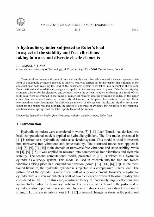
In this paper, the hydraulic cylinder is considered as a slender system. A mathematicalmodel is assumed according to work [11]. The considered hydraulic system presented inFigure 1a consists of two basic elements: the cylinder and the piston rod. Both the cylinderand the piston rod were divided into two parts to build the mathematical model (Fig-ure 1b). The cylinder is modelled by elements denoted as 11 and 12 in Figure 1b while thepiston rod is modelled by elements denoted as 21 and 22. In the considered model of thehydraulic cylinder, the rigidity of the loading nods was taken into account. The rotationalrigidity of the loading nods at both ends of the hydraulic cylinder (springs withrigidities C0 and C1) and the translational rigidity at one end of the hydraulic cylinder (atthe end of the piston fixing) (spring with rigidity C) were also considered.
Fig. 1. Diagram of the considered hydraulic cylinder: a) constructional solution, b) mathematical model
A hydraulic cylinder subjected to Euler’s load in aspect of the stability and free vibrations... 771
The boundary problem of the hydraulic cylinder was formulated in a classic way– on the basis of Hamilton’s principle:
( ) ,02
1
∫ =−t
t
dtVTδ (1)
where:T and V – kinetic and potential energy, respectively,t − time.The buckling of a thick-wall cylinder ending with a piston, affected by the axial
force which generated liquid pressure, is equivalent to the buckling of a rod subjectedto a compressive external load. However in the same work conditions for the cylinderand rod (identical rigidities, the same method of fixing and identical axial forces), thecylinder can undergo damage as a result of the material effort and not due to stabilityloss. There is a different state of stress in the cylinder produced by the liquid pressure.Only a hydraulic cylinder which undergoes damage due to a stability loss is tested inthis work
Potential energy V is written in the form:
( ) ( )
( ) ( )
( ) ( ) ( )( ) .,21,
21,
21
,,21
,21
22222
2
22
22221
2
011
11110
2
1 0
2
11
1111
0
2
2
22
2
1
2
1 0
2
2
2
2222
11
112
tlWCx
txWCx
txWC
xtxW
xtxW
P
dxx
txWEJV
lx
x
j j
jj
i jij
ij
ijijij
ll
l
j
ij
+⎟⎟
⎠
⎞
⎜⎜
⎝
⎛
∂∂
+⎟⎟
⎠
⎞
⎜⎜
⎝
⎛
∂∂
+⎟⎟⎟
⎠
⎞
⎜⎜⎜
⎝
⎛
⎟⎟⎠
⎞⎜⎜⎝
⎛∂
∂+⎟
⎟⎠
⎞⎜⎜⎝
⎛
∂∂
−
−⎟⎟⎠
⎞⎜⎜⎝
⎛
∂
∂=
=
=
=
= =
∑ ∫∫
∑∑ ∫
(2)
Kinetic energy T is defined by the following equation:
( ) ( ) ( ) ( )
( ) ,,21
,21,
21
2
1111
011
21111
2
1
2
1 0
2
2222
11
⎟⎟
⎠
⎞
⎜⎜
⎝
⎛
∂∂
+
+⎟⎠⎞
⎜⎝⎛
∂∂
+⎟⎟⎠
⎞⎜⎜⎝
⎛∂
∂=
=
∫∑∑ ∫= =
lx
ll
ttxWm
dxt
txWAdxt
txWAT
i jCij
ijijij
ij
ρρ
(3)
where:
L. TOMSKI, S. UZNY772
Wij(xij, t) − transversal displacement of the individual elements of the hydraulic cyl-inder defined by coordinate xij,
(EJ)ij − the flexural rigidity of the individual elements of the hydraulic cylinder,(ρA)ij − mass per unit length of the individual elements of the hydraulic cylinder,(ρA)C − mass of liquid per unit length of the cylinder.In the general case of the hydraulic cylinder (the hydraulic cylinder shown in Fig-
ure 1) only one geometrical boundary condition is present at x11 = 0:
( ) .0,011 =tW (4)
Geometrical continuity conditions which occur between adequate elements of thesystem (between elements (Figure 1): 11–12, 11–12–21, 21–22, 12–21–22) are as follows:
( ) ( ) ,,,
012
1111
12
1212
11
1111
=
=
∂∂
=∂
∂
x
lx
xtxW
xtxW (5a)
( ) ( ) ( ),,0,0, 21121111 tWtWtlW == (5b)
( ) ( ) ,,,
022
2112
22
2222
21
2121
=
=
∂∂
=∂
∂
x
lx
xtxW
xtxW (5c)
( ) ( ) ( ).,0,, 2221211212 tWtlWtlW == (5d)
Taking into account the potential energy (2) and kinetic energy (3) and geometricalboundary condition (4) as well as the geometrical continuity conditions (5) in Hamil-ton’s principle (1) the following were obtained:
− the differential equations of motion of the individual elements of the hydrauliccylinder:
( ) ( ) ( ),0
,,,2
2
2
22
4
4
=∂
∂Ψ+
∂
∂+
∂
∂
ttxW
xtxW
kx
txW ijijij
ij
ijijij
ij
ijij
i, j = 1, 2, (6)
where:
( ) ,11
211 EJ
Pk =
A hydraulic cylinder subjected to Euler’s load in aspect of the stability and free vibrations... 773
,0212 =k
( ) ,21
221 EJ
Pk =
( ) ,22
222 EJ
Pk =
( ) ( )( ) ,
11
1111 EJ
AA Cρρ +=Ψ
( )( ) ,
11
1212 EJ
Aρ=Ψ
( )( ) ,
21
2121 EJ
Aρ=Ψ
( )( ) .
22
2222 EJ
Aρ=Ψ
− natural boundary conditions at x11 = 0 and at x22 = l22
( ) ( ) ( ) ,0,,
011
11110
0211
11112
11
1111
=∂
∂−
∂∂
== xxx
txWCx
txWEJ (7)
( ) ( ) ( ) ,0,, 22222222
22
222212
22
22222
22 =∂
∂+
∂∂
== lxlx
xtxWC
xtxWEJ (8)
( ) ( ) ( ) ( )
( ) ,0,
,,,
2222
22222222
22222
2
222222
2222322
22223
22
=∂
∂−
−−∂
∂+
∂∂
=
==
lx
lxlx
ttxWm
tlCWx
txWPx
txWEJ
(9)
− natural continuity conditions between adequate elements of the system (betweenelements (Figure 1): 11–12, 11–12–21, 21–22, 12–21–22):
( ) ( ) ( ) ( ) ,0,,
012
1111
212
12122
12211
11112
11 =∂
∂+
∂∂
−=
=
x
lx
xtxWEJ
xtxWEJ (10a)
L. TOMSKI, S. UZNY774
( ) ( ) ( ) ( ) ,0,,
022
2121
222
22222
22221
21212
21 =∂
∂+
∂∂
−=
=
x
lx
xtxWEJ
xtxWEJ (10b)
( ) ( ) ( ) ( ) ( ) ( )
( ) ( ) ,0,,
,,,
0
00
21
1111
2112
1111
21
2121
11
1111
321
21213
21312
12123
12311
11113
11
=∂
∂−
∂∂
+
+∂
∂−
∂∂
−∂
∂
=
===
=
x
lxxx
lx
xtxWP
xtxWP
xtxWEJ
xtxWEJ
xtxWEJ
(10c)
( ) ( ) ( ) ( )
( ) ( ) .0,
,,
022
21211212
322
22223
22
321
21213
21312
12123
12
=∂
∂−
−∂
∂+
∂∂
=
==
x
lxlx
xtxWEJ
xtxWEJ
xtxWEJ
(10d)
The harmonic solutions to differential Equations (6) are assumed in the form:
( ) ( ) ( ),cos, txYtxW ijijijij ω= (11)
where ω is the natural frequency.Taking into account formula (11) in Equations (6) one can obtain differential equa-
tions which must be fulfilled for the length range of the individual elements of the hy-draulic cylinder xij ∈ (0, lij) at every moment of time t. These new differential equa-tions (after separation of variables) together with the boundary conditions after takinginto account (11) form the boundary problem concerning free vibrations.
3. The solution of the boundary problem
Natural frequencies ω in dependence on the parameters of the system (includingdependences on the external load) can be determined on the basis of the formulatedboundary problem. In this paper the kinetic criterion of stability is used to determinethe critical load of the system (stability problem). On the basis of the kinetic criterionof stability, the critical force of the system corresponds to the first zero natural fre-quency (the considered system is a divergence system).
The solutions to the differential equations obtained after separation of the variablescan be written in the form:
( ) ( ) ( ) ( ) ( ),sincossinhcosh ijijijijijijijijijijijijijij xDxCxBxAxY ββαα +++= (12)
A hydraulic cylinder subjected to Euler’s load in aspect of the stability and free vibrations... 775
where:
,42
242
ijijij
ijkk
Ψ++−= ωα
.42
242
ijijij
ijkk
Ψ++= ωβ
By substituting solution (12) into the boundary conditions after separation of thevariables, a system of homogeneous equations is obtained:
[ ]{ } ,0,,, =ijijijijmn DCBAa i, j = 1, 2; m, n = 1, 2, …, 16. (13)
The matrix determinant of coefficients, equated to zero, is the transcendentalequation, from which the consecutive natural frequencies of the system aredetermined:
.0=mna (14)
4. Stability
The results of numerical simulations concerning the stability problem arepresented in this part of the paper. Numerical research was carried out for differentparameters of the considered hydraulic cylinders, such as the flexural rigidityasymmetry factor for the piston rod and cylinder μa, the degree of coverage ζA, andthe total rigidity factor of the system γ. It was also assumed that the piston rod andthe cylinder are made of the same material. Parameters μa, ζA, γ are defined by thefollowing equations:
( )( ) ,
11
21
EJEJ
a =μ (15a)
,1211
12
lll
A +=ζ (15b)
( )( ) ,
odnEJEJ S=γ (15c)
where:(EJ)S is the rigidity of the hydraulic cylinder, (EJ)S = (EJ)11 + (EJ)21,(EJ)odn is the reference rigidity.
L. TOMSKI, S. UZNY776
Rigidity (EJ)odn has only a comparative character. In this work, rigidity (EJ)odn isequal to the rigidity of the system built from a pipe (cross-section of the pipe − Ar,geometrical axial moment of inertia of the pipe − Jr) and a middle rod (cross-section ofthe rod − Ap, geometrical axial moment of inertia of the rod − Jp), (EJ)odn = E(Jr + Jp).Diameters: dzr − exterior of the pipe, dwr − interior of the pipe, dp − the rod is evaluatedon the basis of a modified equation for slenderness:
( ) ,1211min
gr
w
pr
pr
sll
AAJJ
i +=
++
=μ (16)
where:imin − minimal radius of the gyration of the intersection,sgr − limiting slenderness ratio of material of the hydraulic cylinder,μw − buckling coefficient. The value of the buckling coefficient was assumed as
μw = 1 (which corresponds to the hinged fixed system). For computations ofdiameters: dzr, dwr, dp it was additionally assumed that Jp/Jr = 0.15 and dp/dwr = 0.8.
In this paper, only hydraulic cylinders which undergo damage as a result of a lossof stability and not due to material effort were considered. The part of cylinder filledwith liquid is especially at risk of damage due to material effort. A dangerous excessof stress in this part of cylinder is caused by liquid pressure. The boundary value ofthe flexural rigidity asymmetry factor μgr, where the way in which the damage to thehydraulic cylinder is changing, should be determined assuming the constant flexuralrigidity of the hydraulic cylinder (EJ)S. The damage to the hydraulic cylinder is a re-sult of a stability loss at the coefficient μa ∈ (0, μgr⟩ (this region of coefficient μa isconsidered in this paper). The damage to the hydraulic cylinder is a result of materialeffort at the value of coefficient μa > μgr. The theory of a double extra strong pipe(Lamé theory (compare 0,0, 0,0)) was applied to the computations of stresses in thepart of cylinder which is at risk of liquid pressure action.
In Figures 2–6, the dependence of the boundary value of the flexural rigidity asym-metry factor μgr on the system parameters is presented, while in Figures 2–5, the de-pendence of the boundary value of factor μgr on the degree of coverage of the hydrau-lic cylinder ζA is shown.
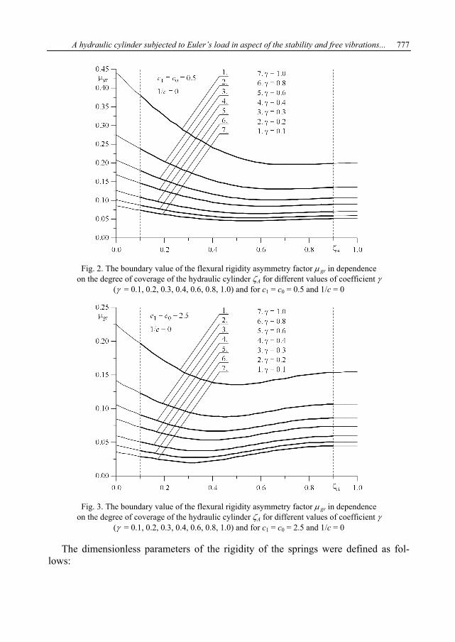
Numerical computations were carried out for different values of total rigidity of thesystem (EJ)S, determined on the basis of coefficient γ and reference rigidity (EJ)odn.Due to the construction it was assumed that the value of the degree of coverage of thehydraulic cylinder ζA was changing in the range ζA ∈ ⟨0.1, 0.9⟩ (thick fragments of thecurves). Identical lengths of the cylinder and the piston (l11 + l12 = l21 + l22) were takeninto account in the numerical computations. The diagrams in Figure 2 were made forthe rigidity values c1 = c0 = 0.5, while the diagrams in Figure 3 were made for the ri-gidity values c1 = c0 = 2.5.
A hydraulic cylinder subjected to Euler’s load in aspect of the stability and free vibrations... 777
Fig. 2. The boundary value of the flexural rigidity asymmetry factor μ gr in dependenceon the degree of coverage of the hydraulic cylinder ζA for different values of coefficient γ
(γ = 0.1, 0.2, 0.3, 0.4, 0.6, 0.8, 1.0) and for c1 = c0 = 0.5 and 1/c = 0
Fig. 3. The boundary value of the flexural rigidity asymmetry factor μ gr in dependenceon the degree of coverage of the hydraulic cylinder ζA for different values of coefficient γ
(γ = 0.1, 0.2, 0.3, 0.4, 0.6, 0.8, 1.0) and for c1 = c0 = 2.5 and 1/c = 0
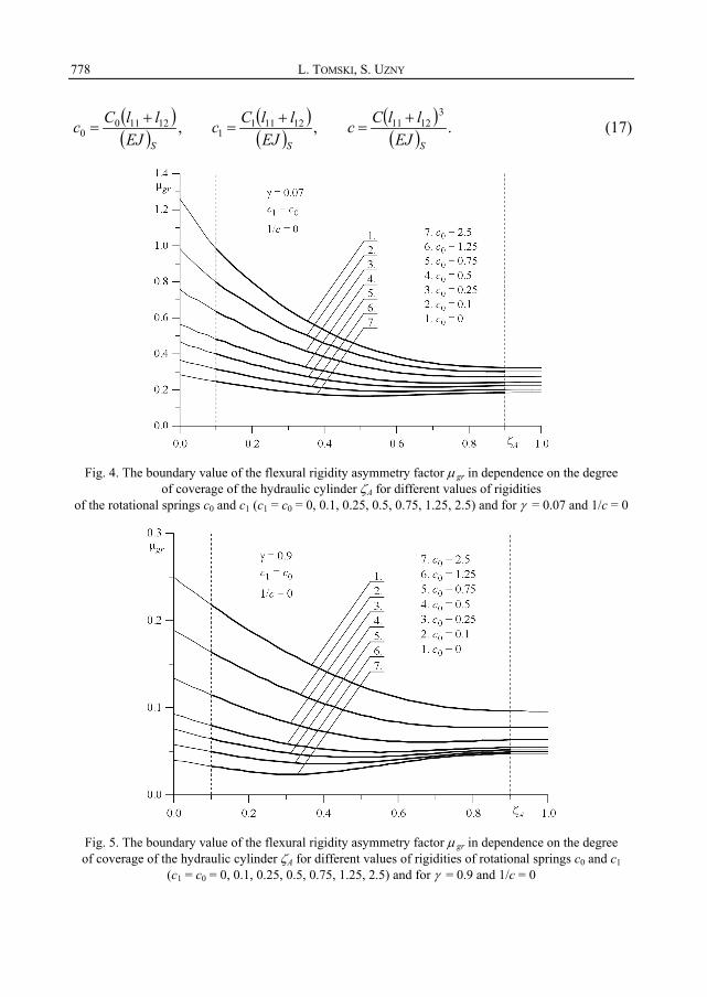
The dimensionless parameters of the rigidity of the springs were defined as fol-lows:
L. TOMSKI, S. UZNY778
( )( ) ,12110
0SEJllCc +
= ( )( ) ,12111
1SEJllCc +
= ( )( ) .
31211
SEJllCc +
= (17)
Fig. 4. The boundary value of the flexural rigidity asymmetry factor μ gr in dependence on the degreeof coverage of the hydraulic cylinder ζA for different values of rigidities
of the rotational springs c0 and c1 (c1 = c0 = 0, 0.1, 0.25, 0.5, 0.75, 1.25, 2.5) and for γ = 0.07 and 1/c = 0
Fig. 5. The boundary value of the flexural rigidity asymmetry factor μ gr in dependence on the degreeof coverage of the hydraulic cylinder ζA for different values of rigidities of rotational springs c0 and c1
(c1 = c0 = 0, 0.1, 0.25, 0.5, 0.75, 1.25, 2.5) and for γ = 0.9 and 1/c = 0
A hydraulic cylinder subjected to Euler’s load in aspect of the stability and free vibrations... 779
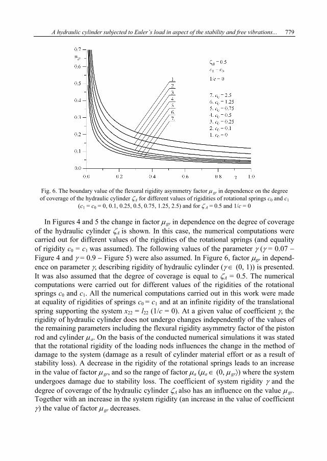
Fig. 6. The boundary value of the flexural rigidity asymmetry factor μ gr in dependence on the degreeof coverage of the hydraulic cylinder ζA for different values of rigidities of rotational springs c0 and c1
(c1 = c0 = 0, 0.1, 0.25, 0.5, 0.75, 1.25, 2.5) and for ζ A = 0.5 and 1/c = 0
In Figures 4 and 5 the change in factor μgr in dependence on the degree of coverageof the hydraulic cylinder ζA is shown. In this case, the numerical computations werecarried out for different values of the rigidities of the rotational springs (and equalityof rigidity c0 = c1 was assumed). The following values of the parameter γ (γ = 0.07 −Figure 4 and γ = 0.9 − Figure 5) were also assumed. In Figure 6, factor μgr in depend-ence on parameter γ, describing rigidity of hydraulic cylinder (γ ∈ (0, 1)) is presented.It was also assumed that the degree of coverage is equal to ζA = 0.5. The numericalcomputations were carried out for different values of the rigidities of the rotationalsprings c0 and c1. All the numerical computations carried out in this work were madeat equality of rigidities of springs c0 = c1 and at an infinite rigidity of the translationalspring supporting the system x22 = l22 (1/c = 0). At a given value of coefficient γ, therigidity of hydraulic cylinder does not undergo changes independently of the values ofthe remaining parameters including the flexural rigidity asymmetry factor of the pistonrod and cylinder μa. On the basis of the conducted numerical simulations it was statedthat the rotational rigidity of the loading nods influences the change in the method ofdamage to the system (damage as a result of cylinder material effort or as a result ofstability loss). A decrease in the rigidity of the rotational springs leads to an increasein the value of factor μgr, and so the range of factor μa (μa ∈ (0, μgr⟩) where the systemundergoes damage due to stability loss. The coefficient of system rigidity γ and thedegree of coverage of the hydraulic cylinder ζA also has an influence on the value μgr.Together with an increase in the system rigidity (an increase in the value of coefficientγ) the value of factor μgr decreases.
L. TOMSKI, S. UZNY780
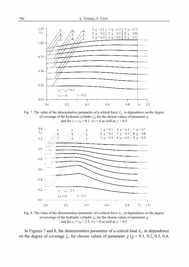
Fig. 7. The value of the dimensionless parameter of a critical force λ cr in dependence on the degreeof coverage of the hydraulic cylinder ζA for the chosen values of parameter χ
and for c1 = c0 = 0.1, 1/c = 0 as well as γ = 0.5
Fig. 8. The value of the dimensionless parameter of a critical force λ cr in dependence on the degreeof coverage of the hydraulic cylinder ζA for the chosen values of parameter χ
and for c1 = c0 = 2.5, 1/c = 0 as well as γ = 0.5
In Figures 7 and 8, the dimensionless parameter of a critical load λcr in dependenceon the degree of coverage ζA for chosen values of parameter χ (χ = 0.1, 0.2, 0.3, 0.4,
A hydraulic cylinder subjected to Euler’s load in aspect of the stability and free vibrations... 781
0.5, 0.6, 0.7, 0.8, 0.9) and γ = 0.5, 1/c = 0 are presented. Computations were carriedout for c0 = c1 = 0.1 (Figure 7) and for c0 = c1 = 2.5 (Figure 8). Parameters λcr andχ were defined in the following way:
( )( ) ,
21211
S
crcr EJ
llP +=λ (18a)
.gr
a
μμχ = (18b)
Parameter χ was introduced to determine the range of factor μa, where the systemundergoes damage due to stability loss.
5. Free vibrations
In respect of the problem of vibrations, the characteristic curves in the plane: thedimensionless parameter of the load λ – the dimensionless parameter of the first fre-quency of free vibrations Ω, were presented. Parameters λ i Ω were defined as fol-lows:
( )( ) ,
21211
SEJllP +
=λ (19a)
( ) ( )( )( )( ) .
412111211
2
SEJllAA ++
=Ωρρω (19b)
Numerical computations concerning free vibrations were carried out for hydrauliccylinders which undergo damage due to stability loss (the value of parameter χ is inthe range χ ∈ ⟨0.1, 0.9⟩).
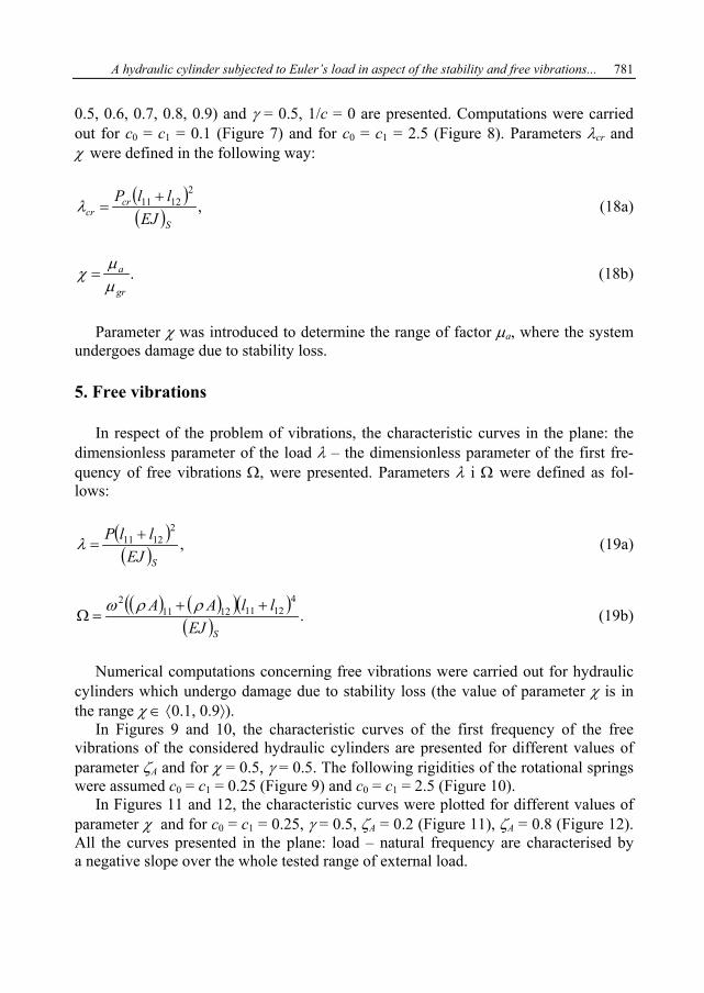
In Figures 9 and 10, the characteristic curves of the first frequency of the freevibrations of the considered hydraulic cylinders are presented for different values ofparameter ζA and for χ = 0.5, γ = 0.5. The following rigidities of the rotational springswere assumed c0 = c1 = 0.25 (Figure 9) and c0 = c1 = 2.5 (Figure 10).
In Figures 11 and 12, the characteristic curves were plotted for different values ofparameter χ and for c0 = c1 = 0.25, γ = 0.5, ζA = 0.2 (Figure 11), ζA = 0.8 (Figure 12).All the curves presented in the plane: load – natural frequency are characterised bya negative slope over the whole tested range of external load.
L. TOMSKI, S. UZNY782
Fig. 9. The characteristic curves in the plane: parameter of the load λ − parameter of the first frequencyof free vibrations Ω for different values of the degree of coverage ζ A (ζ A = 0.1 − 0.9) and for χ = 0.5,
γ = 0.5, c1 = c0 = 0.25 and 1/c = 0
Fig. 10. The characteristic curves in the plane: parameter of the load λ − parameter of the first frequencyof free vibrations Ω for different values of the degree of coverage ζ A (ζ A = 0.1 − 0.9) and for χ = 0.5,
γ = 0.5, c1 = c0 = 2.5 and 1/c = 0
A hydraulic cylinder subjected to Euler’s load in aspect of the stability and free vibrations... 783
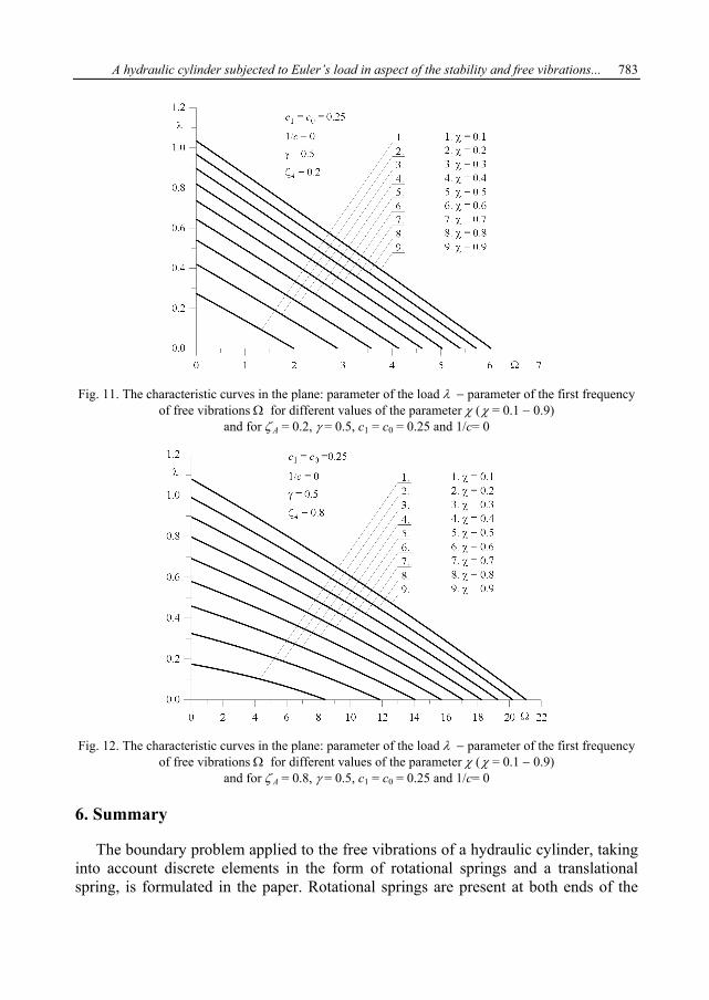
Fig. 11. The characteristic curves in the plane: parameter of the load λ − parameter of the first frequencyof free vibrations Ω for different values of the parameter χ (χ = 0.1 − 0.9)
and for ζ A = 0.2, γ = 0.5, c1 = c0 = 0.25 and 1/c= 0
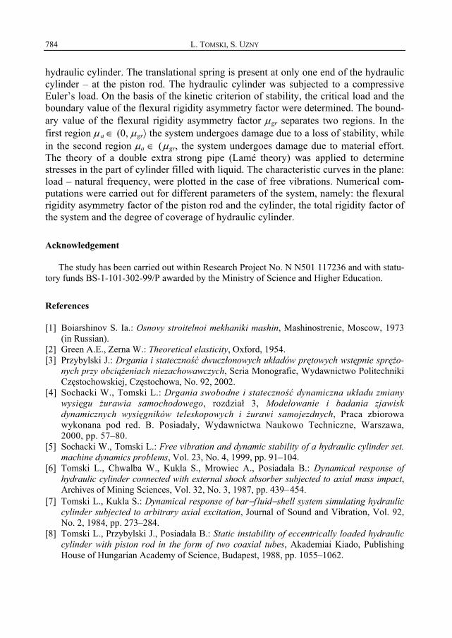
Fig. 12. The characteristic curves in the plane: parameter of the load λ − parameter of the first frequencyof free vibrations Ω for different values of the parameter χ (χ = 0.1 − 0.9)
and for ζ A = 0.8, γ = 0.5, c1 = c0 = 0.25 and 1/c= 0
6. Summary
The boundary problem applied to the free vibrations of a hydraulic cylinder, takinginto account discrete elements in the form of rotational springs and a translationalspring, is formulated in the paper. Rotational springs are present at both ends of the
L. TOMSKI, S. UZNY784
hydraulic cylinder. The translational spring is present at only one end of the hydrauliccylinder – at the piston rod. The hydraulic cylinder was subjected to a compressiveEuler’s load. On the basis of the kinetic criterion of stability, the critical load and theboundary value of the flexural rigidity asymmetry factor were determined. The bound-ary value of the flexural rigidity asymmetry factor μgr separates two regions. In thefirst region μa ∈ (0, μgr⟩ the system undergoes damage due to a loss of stability, whilein the second region μa ∈ (μgr, the system undergoes damage due to material effort.The theory of a double extra strong pipe (Lamé theory) was applied to determinestresses in the part of cylinder filled with liquid. The characteristic curves in the plane:load – natural frequency, were plotted in the case of free vibrations. Numerical com-putations were carried out for different parameters of the system, namely: the flexuralrigidity asymmetry factor of the piston rod and the cylinder, the total rigidity factor ofthe system and the degree of coverage of hydraulic cylinder.
Acknowledgement
The study has been carried out within Research Project No. N N501 117236 and with statu-tory funds BS-1-101-302-99/P awarded by the Ministry of Science and Higher Education.
References
[1] Boiarshinov S. Ia.: Osnovy stroitelnoi mekhaniki mashin, Mashinostrenie, Moscow, 1973(in Russian).
[2] Green A.E., Zerna W.: Theoretical elasticity, Oxford, 1954.[3] Przybylski J.: Drgania i stateczność dwuczłonowych układów prętowych wstępnie sprężo-
nych przy obciążeniach niezachowawczych, Seria Monografie, Wydawnictwo PolitechnikiCzęstochowskiej, Częstochowa, No. 92, 2002.
[4] Sochacki W., Tomski L.: Drgania swobodne i stateczność dynamiczna układu zmianywysięgu żurawia samochodowego, rozdział 3, Modelowanie i badania zjawiskdynamicznych wysięgników teleskopowych i żurawi samojezdnych, Praca zbiorowawykonana pod red. B. Posiadały, Wydawnictwa Naukowo Techniczne, Warszawa,2000, pp. 57–80.
[5] Sochacki W., Tomski L.: Free vibration and dynamic stability of a hydraulic cylinder set.machine dynamics problems, Vol. 23, No. 4, 1999, pp. 91–104.
[6] Tomski L., Chwalba W., Kukla S., Mrowiec A., Posiadała B.: Dynamical response ofhydraulic cylinder connected with external shock absorber subjected to axial mass impact,Archives of Mining Sciences, Vol. 32, No. 3, 1987, pp. 439–454.
[7] Tomski L., Kukla S.: Dynamical response of bar−f luid−shell system simulating hydrauliccylinder subjected to arbitrary axial excitation, Journal of Sound and Vibration, Vol. 92,No. 2, 1984, pp. 273–284.
[8] Tomski L., Przybylski J., Posiadała B.: Static instability of eccentrically loaded hydrauliccylinder with piston rod in the form of two coaxial tubes, Akademiai Kiado, PublishingHouse of Hungarian Academy of Science, Budapest, 1988, pp. 1055–1062.
A hydraulic cylinder subjected to Euler’s load in aspect of the stability and free vibrations... 785
[9] Tomski L., Uzny S.: Stateczność i drgania swobodne siłownika hydraulicznego sprężyściezamocowanego, Zeszyty Naukowe Politechniki Rzeszowskiej, seria: Mechanika, Vol.258, No. 74, 2008, pp. 369–380.
[10] Tomski L.: Dynamika stojaków hydraulicznych obudów górniczych, praca habilitacyjna,Częstochowa, No. 17, 1979.
[11] Tomski L.: Elastic carrying capacity of a hydraulic prop, Engineering Transactions, Vol. 25,No. 2, 1977, pp. 247–263.
[12] Tomski L.: Elastic stability of hydraulic props of longwall supports, Archives of MinningScience, Vol. 23, No. 3, 1978, pp. 217–231.
[13] Tomski L.: Forced vibrations of hydraulic props of longwall supports, Archives of MinningScience, Vol. 24, No. 1, 1979, pp. 19–33.
[14] Tomski L.: Longitudinal mass impact of hydraulic servo, ZAMM, Vol. 61, 1981,pp. 191–193.
[15] Uzny S.: Free vibrations and stability of hydraulic cylinder fixed elastically on both ends,Proc. Appl. Math. Mech., Vol. 9, No. 1, 2009, pp. 303–304.
Siłownik hydrauliczny poddany obciążeniu Eulera w aspekcie statecznościi drgań własnych z uwzględnieniem dyskretnych elementów sprężystych
W niniejszej pracy przeprowadzono badania teoretyczne i numeryczne dotyczące statecz-ności i drgań własnych smukłego układu w postaci siłownika hydraulicznego, który poddanoobciążeniu Eulera. W układzie uwzględniono sztywności w węzłach konstrukcyjnych realizu-jących obciążenie rozważanego układu. W węzłach obciążających zastosowano sprężyny rota-cyjne jak i translacyjne. W ramach badań numerycznych siłownika hydraulicznego określonoobszary współczynnika asymetrii sztywności na zginanie tłoczyska i cylindra, przy którychukład ulega zniszczeniu w wyniku utraty stateczności. W pracy wyznaczono również obciąże-nie krytyczne oraz krzywe charakterystyczne na płaszczyźnie obciążenie−częstość drgań wła-snych. Te dwie wielkości wyznaczono przy różnych wartościach parametrów układu, doktórych zalicza się współczynnik asymetrii sztywności na zginanie tłoczyska i cylindra, stopieńprzekrycia siłownika, sztywności sprężyn rotacyjnych i translacyjnej oraz współczynnik całko-witej sztywności układu.


![THIN CYLINDRICAL SHELLS SUBJECTED TO ......equation will now be applied to an infinitely long thin cylinder loaded, as shown in 1946] CYLINDRICAL SHELLS SUBJECTED TO CONCENTRATED LOADS](https://img.pdfslide.us/doc/110x75/5e976cdbab147d7e621358aa/thin-cylindrical-shells-subjected-to-equation-will-now-be-applied-to-an.jpg)