Embed Size (px)
Citation preview

A Hybrid Hands-on and Simulation Method for Teaching the Operation of Automatic Transmission Systems
Mark Davis, Mehrdaad Ghorashi Department of Engineering
University of Southern Maine
For enhancing the quality of teaching a typical course on design of machines and mechanisms, teaching tools play a vital role. Such tools are needed for helping students understand the operation of complex mechanical systems. One example is the automatic transmission of a passenger car. While students can obtain some information about the operation of an automatic transmission in a textbook, nothing can replace the direct observation of a physical model of an automatic transmission or a computer simulation that demonstrates its operation. This paper presents the process of design, construction and operation of two hands-on teaching tools and the corresponding software simulations that are all dedicated to explaining the operation of an automatic transmission system. The designed and manufactured physical model operates pneumatically and is also capable of providing an estimation for power loss.
Corresponding Author: Mehrdaad Ghorashi, Ph.D., P.E., [email protected]
1. Introduction
Mechanical engineering students learn about planetary gear set theory from textbooks such as [1] where equations are derived, tables are generated and mechanical drawings of gear sets are displayed. One pedagogical problem with this approach is that, as it is seen in Figure 1, these planetary gear sets are inherently compact, concentric and have multiple degrees of freedom. Therefore, making a connection between
Figure 1. A Simpson transmission
the textbook illustrations and the real world application may not be straight forward. The intent of this research is to retrofit an automatic transmission to demonstrate its operation including how its various components are driven and constrained. Once a student has seen the retrofit model of a compound planetary gear set in action (Figure 2, left), he/she can gain a better understanding of the schematic representation of a planetary gear set as seen in Figure 2 (right). In this way, the delivery of the course becomes more student-friendly.
Figure 2. Actual single stage planetary gear set (left) and the corresponding skeleton diagram as presented in [1] (right)

In this research, as illustrated in Figure 3, streamlining the learning process is the main aim. Emphasis is put on first exploring the actual system, and then using that information to understand the abstract illustrations given in a machine dynamics textbook. A SolidWorks model is also generated and related to the real world application, which in this case is a Ford C4 transmission. The
SolidWorks model is then compared to a functional mechanical sketch and finally to the type A single planetary gear set explained in [1]. The transmission has been cut away and automated by a Click PLC controller. All these steps will be explained in detail in the following sections of the paper.
Figure 3. Flow of learning from the real world powered Ford C4 transmission (top row), to SolidWorks model (bottom left), a functional mechanical sketch (bottom middle) and the text book skeleton diagram for type A gear sets (bottom
right). Parts 1 and 5 are sun gears, 2 and 6 are carriers, 3 and 7 are planet gears, and finally 4 and 8 are ring gears
The type A gear train (two of which are used in the Ford C4 transmission) is seen in Figure 3 as a skeleton diagram on the bottom right. This figure flows from left to right and top to bottom, starting with the actual gear train. Then an exploded view of the Simpson transmission follows. In the top right corner an actual planetary gear set is shown for comparison. The SolidWorks illustration of the compound gear set shown in the bottom left picture is a Simpson gear set and it is comprised of two type A gear trains namely; 1, 2, 3, and 4 and their analogues i.e. 5, 6, 7, and 8. To present a
handy sketch of the Simpson gear set, the middle picture in the bottom row is shown. The parts’ colors in this figure follow the same color code as given in the SolidWorks model so that the relation between the two models can be visualized. Where red indicates parts which are splined to the output shaft. These parts are the primary carrier and the secondary ring gears, or 2 and 8. In Figure 4 the exploded view of the actual Simpson gear train is compared to the non-cut away SolidWorks model.
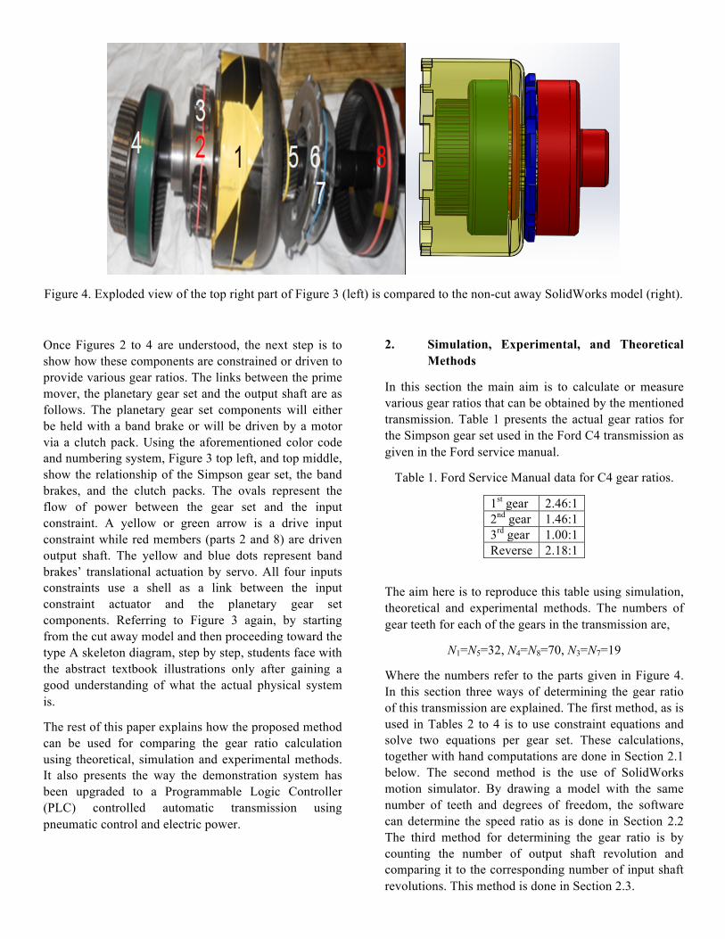
Figure 4. Exploded view of the top right part of Figure 3 (left) is compared to the non-cut away SolidWorks model (right).
Once Figures 2 to 4 are understood, the next step is to show how these components are constrained or driven to provide various gear ratios. The links between the prime mover, the planetary gear set and the output shaft are as follows. The planetary gear set components will either be held with a band brake or will be driven by a motor via a clutch pack. Using the aforementioned color code and numbering system, Figure 3 top left, and top middle, show the relationship of the Simpson gear set, the band brakes, and the clutch packs. The ovals represent the flow of power between the gear set and the input constraint. A yellow or green arrow is a drive input constraint while red members (parts 2 and 8) are driven output shaft. The yellow and blue dots represent band brakes’ translational actuation by servo. All four inputs constraints use a shell as a link between the input constraint actuator and the planetary gear set components. Referring to Figure 3 again, by starting from the cut away model and then proceeding toward the type A skeleton diagram, step by step, students face with the abstract textbook illustrations only after gaining a good understanding of what the actual physical system is.
The rest of this paper explains how the proposed method can be used for comparing the gear ratio calculation using theoretical, simulation and experimental methods. It also presents the way the demonstration system has been upgraded to a Programmable Logic Controller (PLC) controlled automatic transmission using pneumatic control and electric power.
2. Simulation, Experimental, and Theoretical Methods
In this section the main aim is to calculate or measure various gear ratios that can be obtained by the mentioned transmission. Table 1 presents the actual gear ratios for the Simpson gear set used in the Ford C4 transmission as given in the Ford service manual.
Table 1. Ford Service Manual data for C4 gear ratios.
1st gear 2.46:1 2nd gear 1.46:1 3rd gear 1.00:1 Reverse 2.18:1
The aim here is to reproduce this table using simulation, theoretical and experimental methods. The numbers of gear teeth for each of the gears in the transmission are,
N1=N5=32, N4=N8=70, N3=N7=19
Where the numbers refer to the parts given in Figure 4. In this section three ways of determining the gear ratio of this transmission are explained. The first method, as is used in Tables 2 to 4 is to use constraint equations and solve two equations per gear set. These calculations, together with hand computations are done in Section 2.1 below. The second method is the use of SolidWorks motion simulator. By drawing a model with the same number of teeth and degrees of freedom, the software can determine the speed ratio as is done in Section 2.2 The third method for determining the gear ratio is by counting the number of output shaft revolution and comparing it to the corresponding number of input shaft revolutions. This method is done in Section 2.3.
2.1. Theoretical Solution Hand calculations were performed to implement the theory given in [1], and illustrated in Tables 2 to 4 for the 2nd, 3rd and reverse gears. The three mentioned gear ratios, though are embedded in a compound gear set, only utilize a single stage (the 1st gear will be explained separately.) Second and third gears only utilizes
components in the primary (front) gear set while the reverse is comprised of the gears only in the secondary (rear) gear set. The reason why these three gear ratios are generated exclusively in the primary or the secondary part is because of the common sun gear joining the two stages as seen in Figure 3.
Table 2. Angular velocity analysis of the planetary gear set shown in Figure 2 using superposition
Member Member # All rotating with crank
Sun rotates w.r.t. crank
Superposition
Sun 1 X y x+y Crank 2 X 0 X Planet 3 X -(N1/N3)y x-(N1/N3)y Ring 4 X -(N1/N4)y x-(N1/N4)y
Table 3. Application of constraint equations for the information in Table 2; case 1 (overdrive), case 2 (underdrive), and case 3 (reverse), [1]
Case No.
Non-Zero Input
Component
Fixed Component
Output Component
Speed Ratio
1 Crank, 2 Ring, 4 x-
(N1/N4)y=0
Sun, 1 (N1+N4)/ N1
2 Ring, 4 Sun, 1 x+y=0
Crank, 2 N4/(N1+N4)
3 Sun, 1 Crank, 2 x=0
Ring, 4 -N1/N4
Table 4. Using superposition to determine output angular velocities for an input angular velocity of 600 rpm given to Ford C4 transmission. The R, 2, and 3 gear ratios are generated in a single stage.
Input Input Output Gear Ratio 2nd gear Sun held
x+y=0 1st ring
x-(N1/N4)y=600 1st Carrier (Crank)
x 600/411.7=1.46
3rd gear Sun x+y=600
1st ring x-(N1/N4)y=600
1st Carrier (Crank) x
600/600=1
Reverse gear Sun x+y=600
2nd Carrier (Crank) held x=0
2nd ring x-(N1/N4)y
-600/274=-2.19
The first gear uses compound stages so it is more difficult to analyze. Referring to Figure 4, the first gear happens when the output shaft is connected to ring gear 8 (that moves together with the carrier 2) while carrier 6 is held fixed. The input power is given to ring gear 4. In this way, the first gear is not a simple single stage type A gear set. Instead, it is a two stage type A Simpson gear set that uses components from both the primary and the
secondary stages. This compound configuration of the first gear requires four constraint equations for angular velocities as seen in Eqs. (1) to (4). The parts of the secondary gear set, i.e. 5, 6, 7, and 8, are related by the same equations as do their analogs, 1, 2, 3, and 4, given in Table 2. The four constraint equations are solved simultaneously.
𝜔" = 𝜔$ (1)
𝜔% = 𝜔& (2)
𝜔' = 0 (3)
𝜔) = 600rpm (4)
Refering to Table 2, noting that the two stages of the gearset are practically identical, and using index 1 for the first stage and 2 for the second stage, one can write,
𝜔" = 𝑥% (5)
𝜔' = 𝑥" (6)
𝜔) = 𝑥% −1213𝑦% (7)
𝜔$ = 𝑥" −1516𝑦" (8)
Replacing the angular velocity values in Eqs. (1) to (4) by eqyivalent expressions in terms of xi and yi (i=1,2), given in Eqs. (5) to (8), one obtains,
𝑥% = 𝑥" −1516𝑦" (9)
𝑥% + 𝑦% = 𝑥" + 𝑦" (10)
𝑥" = 0 (11)
𝑥% −1213𝑦% = 600 (12)
Equations (9) to (12) can be written in the following matrix form:
1 −11 −1
0 32/701 −1
0 11 0
0 0−32/70 0
𝑥%𝑥"𝑦%𝑦"
=
000600
(13)
or simply, AX=B. Solving this equation results in,
𝑥%𝑥"𝑦%𝑦"
=244.20
−778.3−534.2
(14)
Where all values are in rpm. Recalling that input power is given to ring gear 4 and output power to carrier 2, the resulting gear ratio for this first gear is obtained as:
A3AB= 'CC
D2= 2.46 (15)
This result is compatible with the corresponding gear ratio given in Table 1.
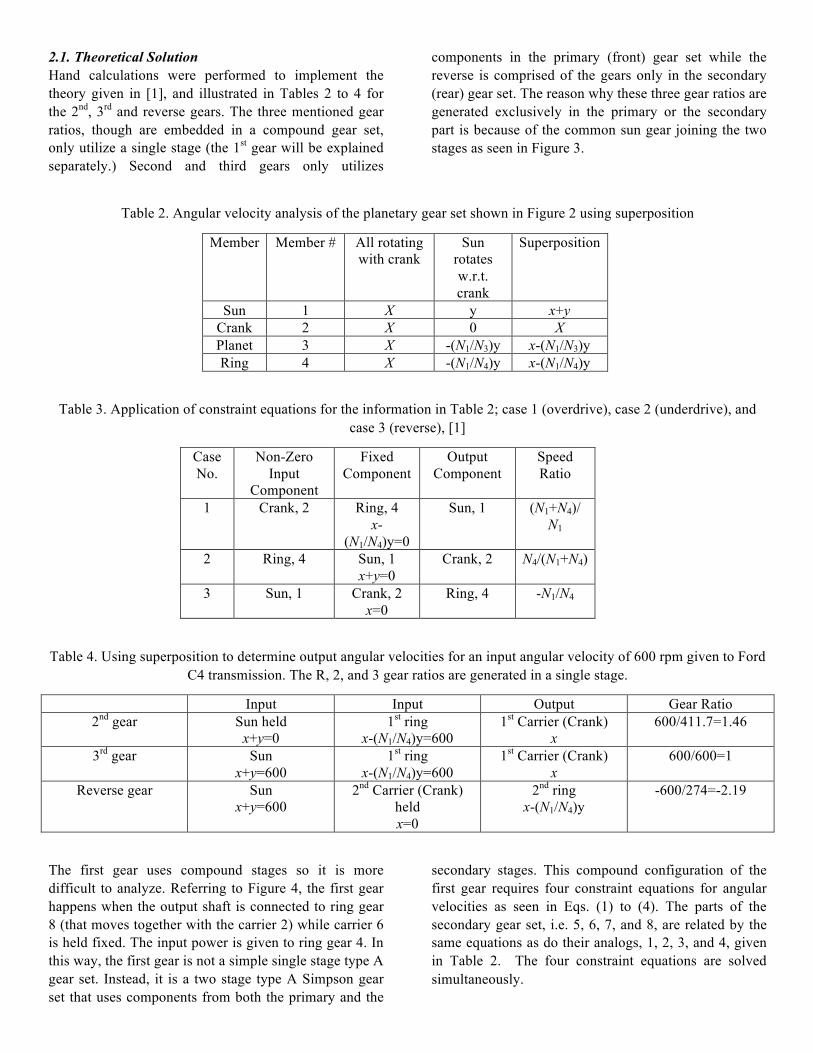
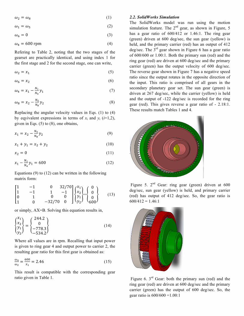
2.2. SolidWorks Simulation The SolidWorks model was run using the motion simulation feature. The 2nd gear, as shown in Figure, 5 has a gear ratio of 600/412 or 1.46:1. The ring gear (green) driven at 600 deg/sec, the sun gear (yellow) is held, and the primary carrier (red) has an output of 412 deg/sec. The 3rd gear shown in Figure 6 has a gear ratio of 600/600 or 1.00:1. Both the primary sun (red) and the ring gear (red) are driven at 600 deg/sec and the primary carrier (green) has the output velocity of 600 deg/sec. The reverse gear shown in Figure 7 has a negative speed ratio since the output rotates in the opposite direction of the input. This ratio is comprised of all gears in the secondary planetary gear set. The sun gear (green) is driven at 267 deg/sec, while the carrier (yellow) is held and the output of -122 deg/sec is recorded for the ring gear (red). This gives reverse a gear ratio of - 2.18:1. These results match Tables 1 and 4.
Figure 5. 2nd Gear: ring gear (green) driven at 600 deg/sec, sun gear (yellow) is held, and primary carrier (red) has output of 412 deg/sec. So, the gear ratio is 600/412 = 1.46:1
Figure 6. 3rd Gear: both the primary sun (red) and the ring gear (red) are driven at 600 deg/sec and the primary carrier (green) has the output of 600 deg/sec. So, the gear ratio is 600/600 =1.00:1
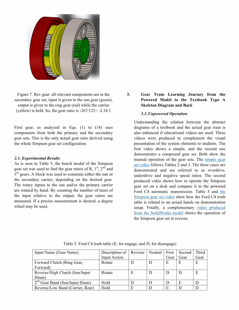
Figure 7. Rev gear: all relevant components are in the secondary gear set, input is given to the sun gear (green),
output is given to the ring gear (red) while the carrier (yellow) is held. So, the gear ratio is -267/122= -2.18:1
First gear, as analyzed in Eqs. (1) to (14) uses components from both the primary and the secondary gear sets. This is the only actual gear ratio derived using the whole Simpson gear set configuration.
2.3. Experimental Results As is seen in Table 5, the bench model of the Simpson gear set was used to find the gear ratios of R, 1st, 2nd and 3rd gears. A block was used to constrain either the sun or the secondary carrier, depending on the desired gear. The rotary inputs to the sun and/or the primary carrier are rotated by hand. By counting the number of turns of the input relative to the output, the gear ratios are measured. If a precise measurement is desired, a degree wheel may be used.
3. Gear Train Learning Journey from the Powered Model to the Textbook Type A Skeleton Diagram and Back
3.1. Unpowered Operation
Understanding the relation between the abstract diagrams of a textbook and the actual gear train is also enhanced if educational videos are used. Three videos were produced to complement the visual presentation of the system elements to students. The first video shows a simple, and the second one demonstrates a compound gear set. Both show the manual operation of the gear sets. The simple gear set video follows Tables 2 and 3. The three cases are demonstrated and are referred to as overdrive, underdrive and negative speed ratios. The second produced video shows how to operate the Simpson gear set on a desk and compare it to the powered Ford C4 automatic transmission. Table 5 and the Simpson gear set video show how the Ford C4 truth table is related to an actual hands on demonstration setup. Finally, a complementary video produced from the SolidWorks model shows the operation of the Simpson gear set in reverse.
Table 5. Ford C4 truth table (E, for engage, and D, for disengage)
Input Name (Gear Name) Description of Input Action
Reverse Neutral First Gear
Second Gear
Third Gear
Forward Clutch (Ring Gear, Forward)
Rotate D D E E E
Reverse/High Clutch (Sun/Input Drum)
Rotate E D D D E
2nd Gear Band (Sun/Input Drum) Hold D D D E D Reverse/Low Band (Carrier, Rear) Hold E D E D D
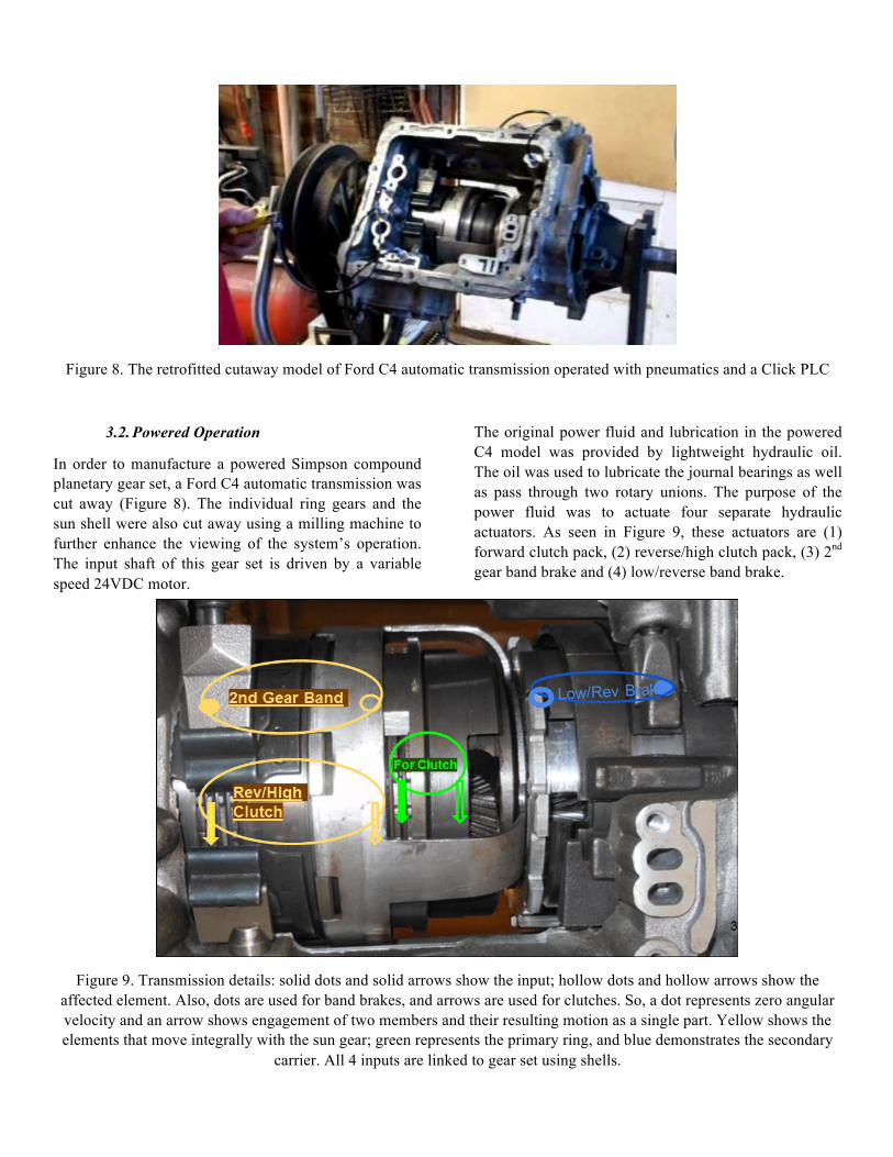
Figure 8. The retrofitted cutaway model of Ford C4 automatic transmission operated with pneumatics and a Click PLC
3.2. Powered Operation
In order to manufacture a powered Simpson compound planetary gear set, a Ford C4 automatic transmission was cut away (Figure 8). The individual ring gears and the sun shell were also cut away using a milling machine to further enhance the viewing of the system’s operation. The input shaft of this gear set is driven by a variable speed 24VDC motor.
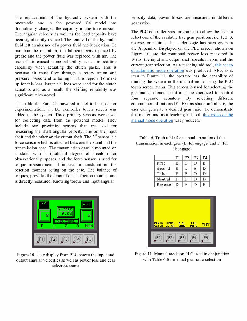
The original power fluid and lubrication in the powered C4 model was provided by lightweight hydraulic oil. The oil was used to lubricate the journal bearings as well as pass through two rotary unions. The purpose of the power fluid was to actuate four separate hydraulic actuators. As seen in Figure 9, these actuators are (1) forward clutch pack, (2) reverse/high clutch pack, (3) 2nd gear band brake and (4) low/reverse band brake.
Figure 9. Transmission details: solid dots and solid arrows show the input; hollow dots and hollow arrows show the affected element. Also, dots are used for band brakes, and arrows are used for clutches. So, a dot represents zero angular velocity and an arrow shows engagement of two members and their resulting motion as a single part. Yellow shows the elements that move integrally with the sun gear; green represents the primary ring, and blue demonstrates the secondary
carrier. All 4 inputs are linked to gear set using shells.
The replacement of the hydraulic system with the pneumatic one in the powered C4 model has dramatically changed the capacity of the transmission. The angular velocity as well as the load capacity have been significantly reduced. The removal of the hydraulic fluid left an absence of a power fluid and lubrication. To maintain the operation, the lubricant was replaced by grease and the power fluid was replaced with air. The use of air caused some reliability issues in shifting capability when actuating the clutch packs. This is because air must flow through a rotary union and pressure losses tend to be high in this region. To make up for this loss, larger air lines were used for the clutch actuators and as a result, the shifting reliability was significantly improved.
To enable the Ford C4 powered model to be used for experimentation, a PLC controller touch screen was added to the system. Three primary sensors were used for collecting data from the powered model. They include two proximity sensors that are used for measuring the shaft angular velocity, one on the input shaft and the other on the output shaft. The 3rd sensor is a force sensor which is attached between the stand and the transmission case. The transmission case is mounted on a stand with a rotational degree of freedom for observational purposes, and the force sensor is used for torque measurement. It imposes a constraint on the reaction moment acting on the case. The balance of torques, provides the amount of the friction moment and is directly measured. Knowing torque and input angular
velocity data, power losses are measured in different gear ratios.
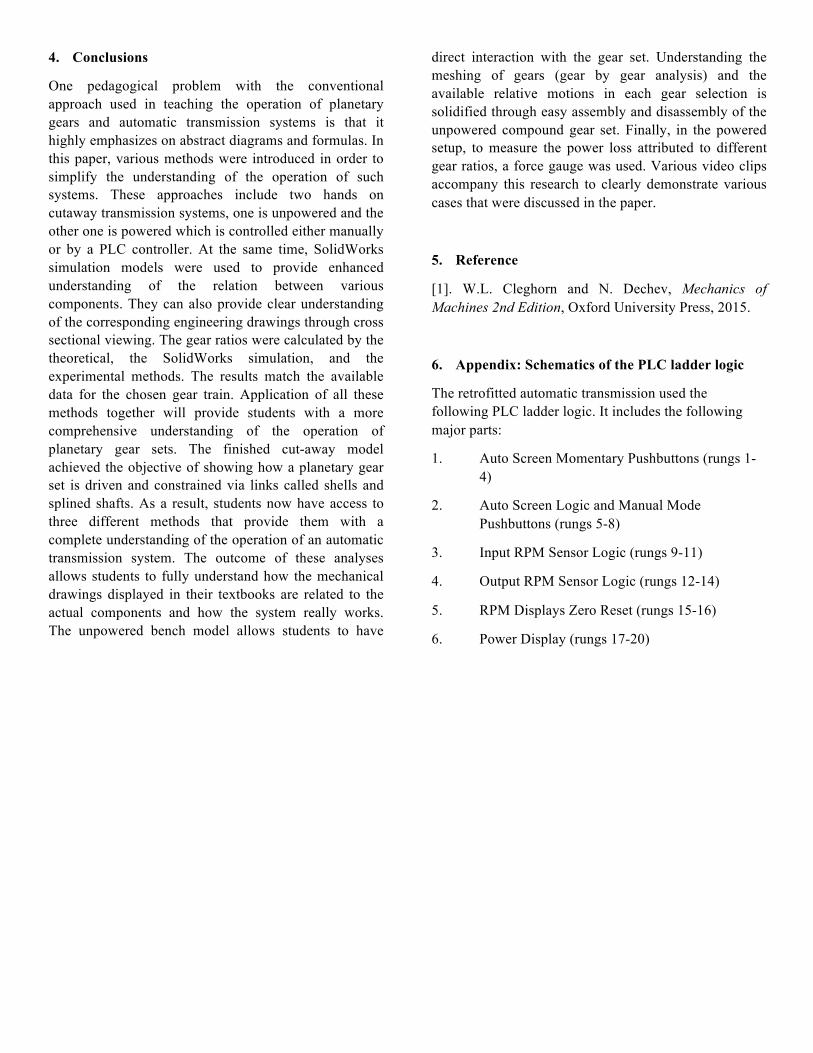
The PLC controller was programed to allow the user to select one of the available five gear positions, i.e. 1, 2, 3, reverse, or neutral. The ladder logic has been given in the Appendix. Displayed on the PLC screen, shown on Figure 10, are the rotational power loss measured in Watts, the input and output shaft speeds in rpm, and the current gear selection. As a teaching aid tool, this video of automatic mode operation was produced. Also, as is seen in Figure 11, the operator has the capability of running the system in the manual mode using the PLC touch screen menu. This screen is used for selecting the pneumatic solenoids that must be energized to control four separate actuators. By selecting different combination of buttons (F1-F5), as stated in Table 6, the user can generate a desired gear ratio. To demonstrate this matter, and as a teaching aid tool, this video of the manual mode operation was produced.
Table 6. Truth table for manual operation of the transmission in each gear (E, for engage, and D, for
disengage)
F1 F2 F3 F4 First E D D E Second E D E D Third E E D D Neutral D D D D Reverse D E D E
Figure 10. User display from PLC shows the input and output angular velocities as well as power loss and gear
selection status
Figure 11. Manual mode on PLC used in conjunction with Table 6 for manual gear ratio selection
4. Conclusions
One pedagogical problem with the conventional approach used in teaching the operation of planetary gears and automatic transmission systems is that it highly emphasizes on abstract diagrams and formulas. In this paper, various methods were introduced in order to simplify the understanding of the operation of such systems. These approaches include two hands on cutaway transmission systems, one is unpowered and the other one is powered which is controlled either manually or by a PLC controller. At the same time, SolidWorks simulation models were used to provide enhanced understanding of the relation between various components. They can also provide clear understanding of the corresponding engineering drawings through cross sectional viewing. The gear ratios were calculated by the theoretical, the SolidWorks simulation, and the experimental methods. The results match the available data for the chosen gear train. Application of all these methods together will provide students with a more comprehensive understanding of the operation of planetary gear sets. The finished cut-away model achieved the objective of showing how a planetary gear set is driven and constrained via links called shells and splined shafts. As a result, students now have access to three different methods that provide them with a complete understanding of the operation of an automatic transmission system. The outcome of these analyses allows students to fully understand how the mechanical drawings displayed in their textbooks are related to the actual components and how the system really works. The unpowered bench model allows students to have
direct interaction with the gear set. Understanding the meshing of gears (gear by gear analysis) and the available relative motions in each gear selection is solidified through easy assembly and disassembly of the unpowered compound gear set. Finally, in the powered setup, to measure the power loss attributed to different gear ratios, a force gauge was used. Various video clips accompany this research to clearly demonstrate various cases that were discussed in the paper.
5. Reference
[1]. W.L. Cleghorn and N. Dechev, Mechanics of Machines 2nd Edition, Oxford University Press, 2015.
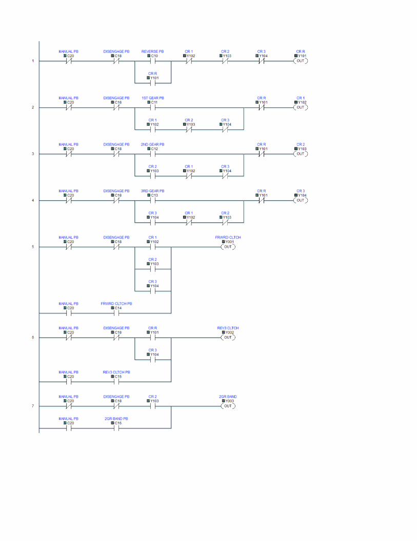
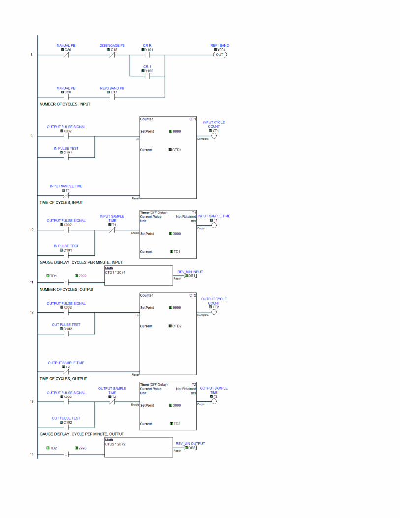
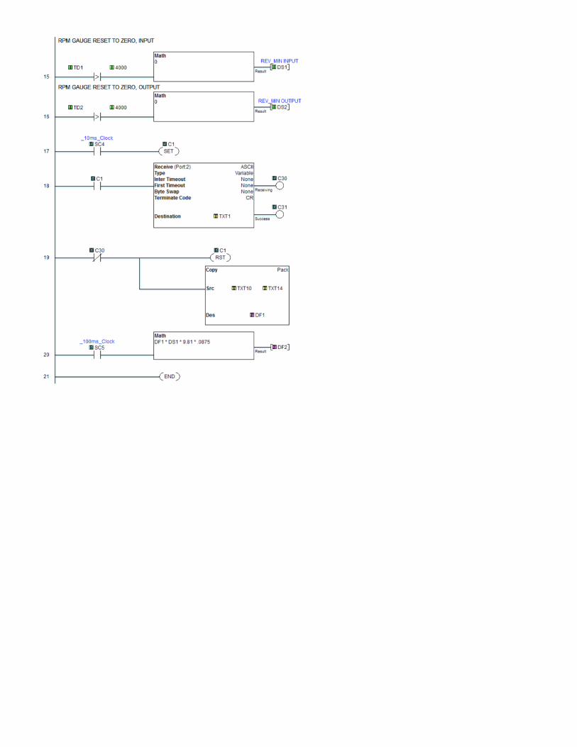
6. Appendix: Schematics of the PLC ladder logic
The retrofitted automatic transmission used the following PLC ladder logic. It includes the following major parts:
1. Auto Screen Momentary Pushbuttons (rungs 1-4)
2. Auto Screen Logic and Manual Mode Pushbuttons (rungs 5-8)
3. Input RPM Sensor Logic (rungs 9-11)
4. Output RPM Sensor Logic (rungs 12-14)
5. RPM Displays Zero Reset (rungs 15-16)
6. Power Display (rungs 17-20)