Embed Size (px)
Citation preview
International Journal of Science and Research (IJSR) ISSN (Online): 2319-7064
Impact Factor (2012): 3.358
Volume 3 Issue 11, November 2014 www.ijsr.net
Licensed Under Creative Commons Attribution CC BY
A High Step-Up Three-Port DC–DC Converter for Stand-Alone PV/Battery Power Systems
Dr. K. Ravichandrudu1, P. Suman Pramod Kumar2, K. Seshu3
1Professor, Department of EEE, NRI Institute of Technology, Guntur
2Head & Associate Professor, Department of EEE, Guntur Engineering College, Guntur
3PG Schollor, Chadalawada Ramanamma Engineering College, Tirupathi
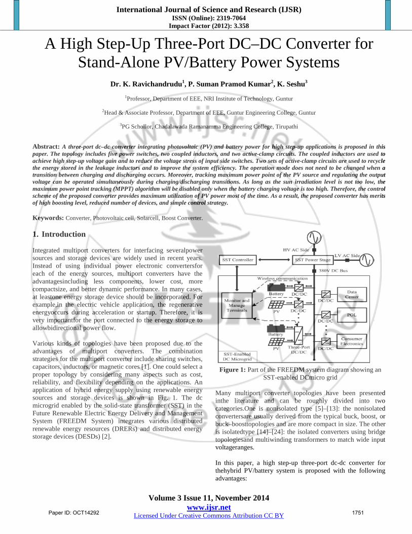
Abstract: A three-port dc–dc converter integrating photovoltaic (PV) and battery power for high step-up applications is proposed in this paper. The topology includes five power switches, two coupled inductors, and two active-clamp circuits. The coupled inductors are used to achieve high step-up voltage gain and to reduce the voltage stress of input side switches. Two sets of active-clamp circuits are used to recycle the energy stored in the leakage inductors and to improve the system efficiency. The operation mode does not need to be changed when a transition between charging and discharging occurs. Moreover, tracking maximum power point of the PV source and regulating the output voltage can be operated simultaneously during charging/discharging transitions. As long as the sun irradiation level is not too low, the maximum power point tracking (MPPT) algorithm will be disabled only when the battery charging voltage is too high. Therefore, the control scheme of the proposed converter provides maximum utilization of PV power most of the time. As a result, the proposed converter has merits of high boosting level, reduced number of devices, and simple control strategy. Keywords: Converter, Photovoltaic cell, Solarcell, Boost Converter. 1. Introduction Integrated multiport converters for interfacing severalpower sources and storage devices are widely used in recent years. Instead of using individual power electronic convertersfor each of the energy sources, multiport converters have the advantagesincluding less components, lower cost, more compactsize, and better dynamic performance. In many cases, at leastone energy storage device should be incorporated. For example,in the electric vehicle application, the regenerative energyoccurs during acceleration or startup. Therefore, it is very importantfor the port connected to the energy storage to allowbidirectional power flow. Various kinds of topologies have been proposed due to the advantages of multiport converters. The combination strategies for the multiport converter include sharing switches, capacitors, inductors, or magnetic cores [1]. One could select a proper topology by considering many aspects such as cost, reliability, and flexibility depending on the applications. An application of hybrid energy supply using renewable energy sources and storage devices is shown in Fig. 1. The dc microgrid enabled by the solid-state transformer (SST) in the Future Renewable Electric Energy Delivery and Management System (FREEDM System) integrates various distributed renewable energy resources (DRERs) and distributed energy storage devices (DESDs) [2].
Figure 1: Part of the FREEDM system diagram showing an
SST-enabled DCmicro grid Many multiport converter topologies have been presented inthe literature and can be roughly divided into two categories.One is nonisolated type [5]–[13]: the nonisolated convertersare usually derived from the typical buck, boost, or buck–boosttopologies and are more compact in size. The other is isolatedtype [14]–[24]: the isolated converters using bridge topologiesand multiwinding transformers to match wide input voltageranges. In this paper, a high step-up three-port dc-dc converter for thehybrid PV/battery system is proposed with the following advantages:
Paper ID: OCT14292 1751
International Journal of Science and Research (IJSR) ISSN (Online): 2319-7064
Impact Factor (2012): 3.358
Volume 3 Issue 11, November 2014 www.ijsr.net
Licensed Under Creative Commons Attribution CC BY
1) High voltage conversion ratio is achieved by usingcoupled inductors;
2) Simple converter topology which has reducednumber of the switches and associate circuits;
3) Simplecontrol strategy which does not need to change the operationmode after a charging/discharging transition occurs unless thecharging voltage is too high; and
4) Output voltage is alwaysregulated at 380 V under all operation modes.
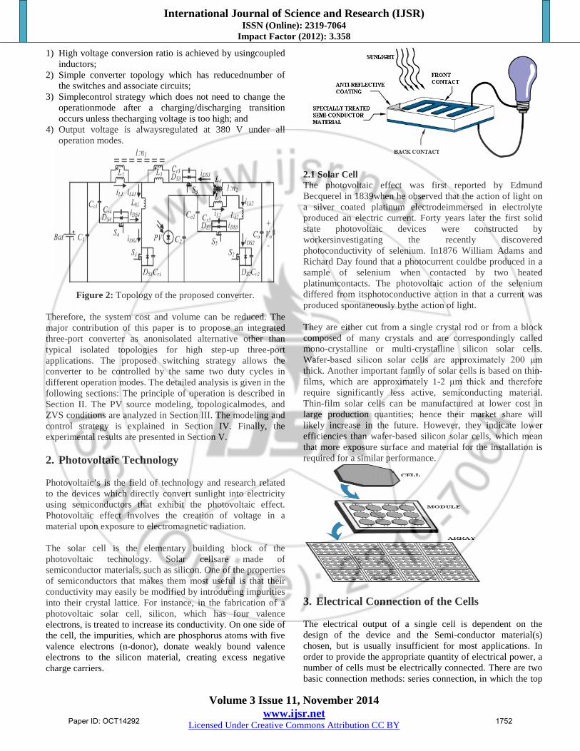
Figure 2: Topology of the proposed converter.
Therefore, the system cost and volume can be reduced. The major contribution of this paper is to propose an integrated three-port converter as anonisolated alternative other than typical isolated topologies for high step-up three-port applications. The proposed switching strategy allows the converter to be controlled by the same two duty cycles in different operation modes. The detailed analysis is given in the following sections: The principle of operation is described in Section II. The PV source modeling, topologicalmodes, and ZVS conditions are analyzed in Section III. The modeling and control strategy is explained in Section IV. Finally, the experimental results are presented in Section V. 2. Photovoltaic Technology Photovoltaic’s is the field of technology and research related to the devices which directly convert sunlight into electricity using semiconductors that exhibit the photovoltaic effect. Photovoltaic effect involves the creation of voltage in a material upon exposure to electromagnetic radiation. The solar cell is the elementary building block of the photovoltaic technology. Solar cellsare made of semiconductor materials, such as silicon. One of the properties of semiconductors that makes them most useful is that their conductivity may easily be modified by introducing impurities into their crystal lattice. For instance, in the fabrication of a photovoltaic solar cell, silicon, which has four valence electrons, is treated to increase its conductivity. On one side of the cell, the impurities, which are phosphorus atoms with five valence electrons (n-donor), donate weakly bound valence electrons to the silicon material, creating excess negative charge carriers.
2.1 Solar Cell The photovoltaic effect was first reported by Edmund Becquerel in 1839when he observed that the action of light on a silver coated platinum electrodeimmersed in electrolyte produced an electric current. Forty years later the first solid state photovoltaic devices were constructed by workersinvestigating the recently discovered photoconductivity of selenium. In1876 William Adams and Richard Day found that a photocurrent couldbe produced in a sample of selenium when contacted by two heated platinumcontacts. The photovoltaic action of the selenium differed from itsphotoconductive action in that a current was produced spontaneously bythe action of light. They are either cut from a single crystal rod or from a block composed of many crystals and are correspondingly called mono-crystalline or multi-crystalline silicon solar cells. Wafer-based silicon solar cells are approximately 200 μm thick. Another important family of solar cells is based on thin-films, which are approximately 1-2 μm thick and therefore require significantly less active, semiconducting material. Thin-film solar cells can be manufactured at lower cost in large production quantities; hence their market share will likely increase in the future. However, they indicate lower efficiencies than wafer-based silicon solar cells, which mean that more exposure surface and material for the installation is required for a similar performance.
3. Electrical Connection of the Cells The electrical output of a single cell is dependent on the design of the device and the Semi-conductor material(s) chosen, but is usually insufficient for most applications. In order to provide the appropriate quantity of electrical power, a number of cells must be electrically connected. There are two basic connection methods: series connection, in which the top
Paper ID: OCT14292 1752

International Journal of Science and Research (IJSR) ISSN (Online): 2319-7064
Impact Factor (2012): 3.358
Volume 3 Issue 11, November 2014 www.ijsr.net
Licensed Under Creative Commons Attribution CC BY
contact of each cell is connected to the back contact of the next cell in the sequence, and parallel connection, in which all the top contacts are connected together, as are all the bottom contacts. In both cases, this results in just two electrical connection points for the group of cells. a) Series connection: Figure shows the series connection of three individual cells as an example and the resultant group of connected cells is commonly referred to as a series string. The current output of the string is equivalent to the current of a single cell, but the voltage output is increased, being an addition of the voltages from all the cells in the string (i.e. in this case, the voltage output is equal to 3Vcell).
Figure: Series connection of cells, with resulting current–
voltage characteristic. It is important to have well matched cells in the series string, particularly with respect to current. If one cell produces a significantly lower current than the other cells (under the same illumination conditions), then the string will operate at that lower current level and the remaining cells will not be operating at their maximum power points. b) Parallel connection Figure shows the parallel connection of three individual cells as an example. In this case, the current from the cell group is equivalent to the addition of the current from each cell (in this case, 3 I cell), but the voltage remains equivalent to that of a single cell. As before, it is important to have the cells well matched in order to gain maximum output, but this time the voltage is the important parameter since all cells must be at the same operating voltage. If the voltage at the maximum power point is substantially different for one of the cells, then this will force all the cells to operate off their maximum power point, with the poorer cell being pushed towards its open-circuit voltage value and the better cells to voltages below the maximum power point voltage. In all cases, the power level will be reduced below the optimum.
Figure: Parallel connection of cells, with resulting current–
voltage characteristic
3.1 Tilt Angle and Orientation The orientation of the module with respect to the direction of the Sun determines theintensity of the sunlight falling on the module surface. Two main parameters aredefined to describe this. The first is the tilt angle, which is the angle between the plane of the module and the horizontal. The second parameter is the azimuth angle, which isthe angle between the plane of the module and due south (or sometimes due northdepending on the definition used). Correction of the direct normal irradiance to that onany surface can be determined using the cosine of the angle between the normal to theSun and the module plane. The optimum array orientation will depend on the latitude of the site, prevailingweather conditions and the loads to be met. It is generally accepted that, for lowlatitudes, the maximum annual output is obtained when the array tilt angle is roughlyequal to the latitude angle and the array faces due south (in the northern hemisphere)or due north (for the southern hemisphere). For higher latitudes, such as those innorthern Europe, the maximum output is usually obtained for tilt angles ofapproximately the latitude angle minus 10–15 degrees. The optimum tilt angle is alsoaffected by the proportion of diffuse radiation in the sunlight, since diffuse light isonly weakly directional. Therefore, for locations with a high proportion of diffusesunlight, the effect of tilt angle is reduced. The maximum insulation level is obtained for a south-facing surface at a tilt angle ofabout 35 degrees, as would be expected for a latitude of about 51oN. However, theisolation level varies by less than 10% with changing azimuth angle at this tilt angle.A similarly low variation is observed for south facing surfaces for a variation of +/- 30degrees from the optimum tilt angle.
Figure: Percentage variation of annual sunlight levels as a
function of tilt angle and azimuth angle
Paper ID: OCT14292 1753
International Journal of Science and Research (IJSR) ISSN (Online): 2319-7064
Impact Factor (2012): 3.358
Volume 3 Issue 11, November 2014 www.ijsr.net
Licensed Under Creative Commons Attribution CC BY
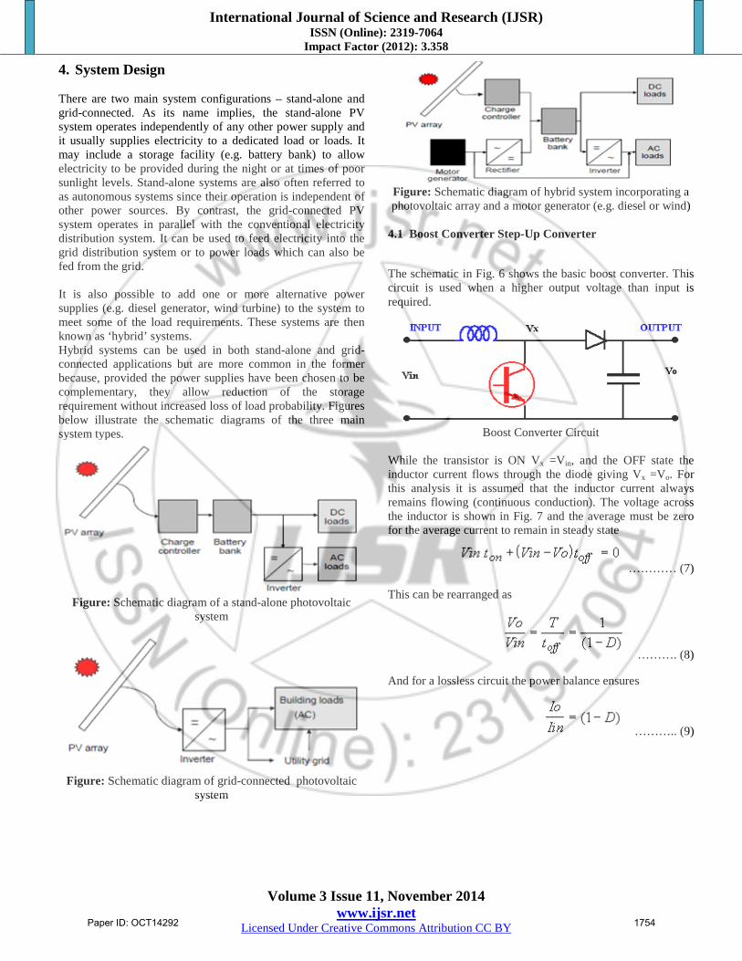
4. System Design There are two main system configurations – stand-alone and grid-connected. As its name implies, the stand-alone PV system operates independently of any other power supply and it usually supplies electricity to a dedicated load or loads. It may include a storage facility (e.g. battery bank) to allow electricity to be provided during the night or at times of poor sunlight levels. Stand-alone systems are also often referred to as autonomous systems since their operation is independent of other power sources. By contrast, the grid-connected PV system operates in parallel with the conventional electricity distribution system. It can be used to feed electricity into the grid distribution system or to power loads which can also be fed from the grid. It is also possible to add one or more alternative power supplies (e.g. diesel generator, wind turbine) to the system to meet some of the load requirements. These systems are then known as ‘hybrid’ systems. Hybrid systems can be used in both stand-alone and grid-connected applications but are more common in the former because, provided the power supplies have been chosen to be complementary, they allow reduction of the storage requirement without increased loss of load probability. Figures below illustrate the schematic diagrams of the three main system types.
Figure: Schematic diagram of a stand-alone photovoltaic
system
Figure: Schematic diagram of grid-connected photovoltaic
system
Figure: Schematic diagram of hybrid system incorporating a photovoltaic array and a motor generator (e.g. diesel or wind)
4.1 Boost Converter Step-Up Converter
The schematic in Fig. 6 shows the basic boost converter. This circuit is used when a higher output voltage than input is required.
Boost Converter Circuit
While the transistor is ON Vx =Vin, and the OFF state the inductor current flows through the diode giving Vx =Vo. For this analysis it is assumed that the inductor current always remains flowing (continuous conduction). The voltage across the inductor is shown in Fig. 7 and the average must be zero for the average current to remain in steady state
………… (7)
This can be rearranged as
………. (8)
And for a lossless circuit the power balance ensures
……….. (9)
Paper ID: OCT14292 1754
International Journal of Science and Research (IJSR) ISSN (Online): 2319-7064
Impact Factor (2012): 3.358
Volume 3 Issue 11, November 2014 www.ijsr.net
Licensed Under Creative Commons Attribution CC BY
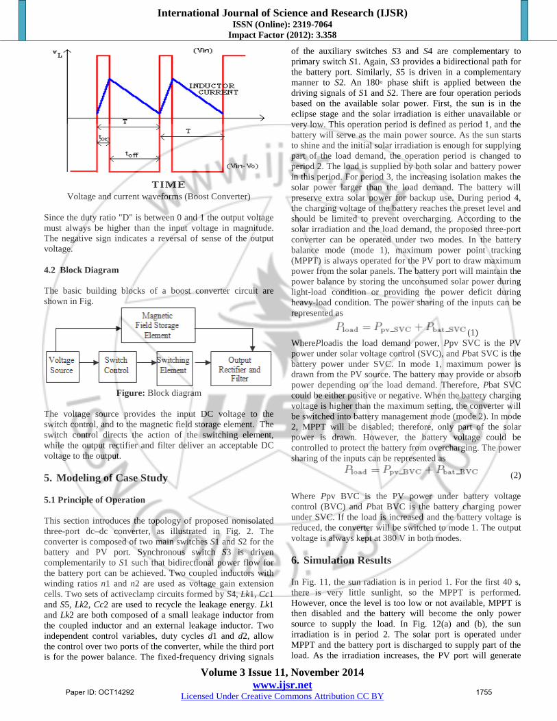
Voltage and current waveforms (Boost Converter)
Since the duty ratio "D" is between 0 and 1 the output voltage must always be higher than the input voltage in magnitude. The negative sign indicates a reversal of sense of the output voltage. 4.2 Block Diagram The basic building blocks of a boost converter circuit are shown in Fig.
Figure: Block diagram
The voltage source provides the input DC voltage to the switch control, and to the magnetic field storage element. The switch control directs the action of the switching element, while the output rectifier and filter deliver an acceptable DC voltage to the output. 5. Modeling of Case Study 5.1 Principle of Operation This section introduces the topology of proposed nonisolated three-port dc–dc converter, as illustrated in Fig. 2. The converter is composed of two main switches S1 and S2 for the battery and PV port. Synchronous switch S3 is driven complementarily to S1 such that bidirectional power flow for the battery port can be achieved. Two coupled inductors with winding ratios n1 and n2 are used as voltage gain extension cells. Two sets of activeclamp circuits formed by S4, Lk1, Cc1 and S5, Lk2, Cc2 are used to recycle the leakage energy. Lk1 and Lk2 are both composed of a small leakage inductor from the coupled inductor and an external leakage inductor. Two independent control variables, duty cycles d1 and d2, allow the control over two ports of the converter, while the third port is for the power balance. The fixed-frequency driving signals
of the auxiliary switches S3 and S4 are complementary to primary switch S1. Again, S3 provides a bidirectional path for the battery port. Similarly, S5 is driven in a complementary manner to S2. An 180◦ phase shift is applied between the driving signals of S1 and S2. There are four operation periods based on the available solar power. First, the sun is in the eclipse stage and the solar irradiation is either unavailable or very low. This operation period is defined as period 1, and the battery will serve as the main power source. As the sun starts to shine and the initial solar irradiation is enough for supplying part of the load demand, the operation period is changed to period 2. The load is supplied by both solar and battery power in this period. For period 3, the increasing isolation makes the solar power larger than the load demand. The battery will preserve extra solar power for backup use. During period 4, the charging voltage of the battery reaches the preset level and should be limited to prevent overcharging. According to the solar irradiation and the load demand, the proposed three-port converter can be operated under two modes. In the battery balance mode (mode 1), maximum power point tracking (MPPT) is always operated for the PV port to draw maximum power from the solar panels. The battery port will maintain the power balance by storing the unconsumed solar power during light-load condition or providing the power deficit during heavy-load condition. The power sharing of the inputs can be represented as
(1) WherePloadis the load demand power, Ppv SVC is the PV power under solar voltage control (SVC), and Pbat SVC is the battery power under SVC. In mode 1, maximum power is drawn from the PV source. The battery may provide or absorb power depending on the load demand. Therefore, Pbat SVC could be either positive or negative. When the battery charging voltage is higher than the maximum setting, the converter will be switched into battery management mode (mode 2). In mode 2, MPPT will be disabled; therefore, only part of the solar power is drawn. However, the battery voltage could be controlled to protect the battery from overcharging. The power sharing of the inputs can be represented as
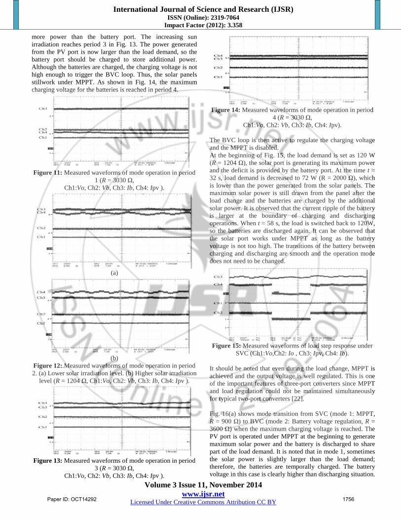
(2) Where Ppv BVC is the PV power under battery voltage control (BVC) and Pbat BVC is the battery charging power under SVC. If the load is increased and the battery voltage is reduced, the converter will be switched to mode 1. The output voltage is always kept at 380 V in both modes. 6. Simulation Results In Fig. 11, the sun radiation is in period 1. For the first 40 s, there is very little sunlight, so the MPPT is performed. However, once the level is too low or not available, MPPT is then disabled and the battery will become the only power source to supply the load. In Fig. 12(a) and (b), the sun irradiation is in period 2. The solar port is operated under MPPT and the battery port is discharged to supply part of the load. As the irradiation increases, the PV port will generate
Paper ID: OCT14292 1755
International Journal of Science and Research (IJSR) ISSN (Online): 2319-7064
Impact Factor (2012): 3.358
Volume 3 Issue 11, November 2014 www.ijsr.net
Licensed Under Creative Commons Attribution CC BY
more power than the battery port. The increasing sun irradiation reaches period 3 in Fig. 13. The power generated from the PV port is now larger than the load demand, so the battery port should be charged to store additional power. Although the batteries are charged, the charging voltage is not high enough to trigger the BVC loop. Thus, the solar panels stillwork under MPPT. As shown in Fig. 14, the maximum charging voltage for the batteries is reached in period 4.
Figure 11: Measured waveforms of mode operation in period
1 (R = 3030 Ω, Ch1:Vo, Ch2: Vb, Ch3: Ib, Ch4: Ipv ).
(a)
(b)
Figure 12:.Measured waveforms of mode operation in period 2. (a) Lower solar irradiation level. (b) Higher solar irradiation
level (R = 1204 Ω, Ch1:Vo, Ch2: Vb, Ch3: Ib, Ch4: Ipv ).
Figure 13: Measured waveforms of mode operation in period
3 (R = 3030 Ω, Ch1:Vo, Ch2: Vb, Ch3: Ib, Ch4: Ipv ).
Figure 14: Measured waveforms of mode operation in period
4 (R = 3030 Ω, Ch1:Vo, Ch2: Vb, Ch3: Ib, Ch4: Ipv).
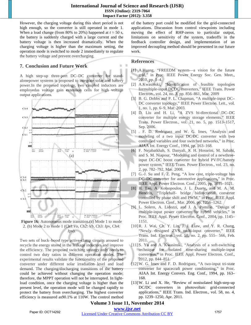
The BVC loop is then active to regulate the charging voltage and the MPPT is disabled. At the beginning of Fig. 15, the load demand is set as 120 W (R = 1204 Ω), the solar port is generating its maximum power and the deficit is provided by the battery port. At the time t ≈ 32 s, load demand is decreased to 72 W (R = 2000 Ω), which is lower than the power generated from the solar panels. The maximum solar power is still drawn from the panel after the load change and the batteries are charged by the additional solar power. It is observed that the current ripple of the battery is larger at the boundary of charging and discharging operations. When t ≈ 58 s, the load is switched back to 120W, so the batteries are discharged again. It can be observed that the solar port works under MPPT as long as the battery voltage is not too high. The transitions of the battery between charging and discharging are smooth and the operation mode does not need to be changed.
Figure 15: Measured waveforms of load step response under
SVC (Ch1:Vo,Ch2: Io , Ch3: Ipv, Ch4: Ib). It should be noted that even during the load change, MPPT is achieved and the output voltage is well regulated. This is one of the important features of three-port converters since MPPT and load regulation could not be maintained simultaneously for typical two-port converters [22]. Fig. 16(a) shows mode transition from SVC (mode 1: MPPT, R = 900 Ω) to BVC (mode 2: Battery voltage regulation, R = 3600 Ω) when the maximum charging voltage is reached. The PV port is operated under MPPT at the beginning to generate maximum solar power and the battery is discharged to share part of the load demand. It is noted that in mode 1, sometimes the solar power is slightly larger than the load demand; therefore, the batteries are temporally charged. The battery voltage in this case is clearly higher than discharging situation.
Paper ID: OCT14292 1756
International Journal of Science and Research (IJSR) ISSN (Online): 2319-7064
Impact Factor (2012): 3.358
Volume 3 Issue 11, November 2014 www.ijsr.net
Licensed Under Creative Commons Attribution CC BY
However, the charging voltage during this short period is not high enough, so the converter is still operated in mode 1. When a load change (from 80% to 20%) happened at t ≈ 50 s, the battery is suddenly charged with a large current and the battery voltage is then increased dramatically. When the charging voltage is higher than the maximum setting, the operation mode is switched to mode 2 immediately to regulate the battery voltage and prevent overcharging. 7. Conclusion and Future Work A high step-up three-port DC–DC converter for stand-alonepower systems is proposed to integrate solar and battery power.In the proposed topology, two coupled inductors are employedas voltage gain extension cells for high voltage output applications.
(a)
Figure 16: Autonomous mode transition.(a) Mode 1 to mode 2. (b) Mode 2 to mode 1 (Ch1:Vo, Ch2: Vb, Ch3: Ipv, Ch4:
Ipv). Two sets of buck–boost type active-clamp circuits aroused to recycle the energy stored in the leakage inductors and improve the efficiency. The proposed switching strategy only needs to control two duty ratios in different operation modes. The experimental results validate the functionality of the proposed converter under different solar irradiation level and load demand. The charging/discharging transitions of the battery could be achieved without changing the operation mode; therefore, the MPPT operation will not be interrupted. In light-load condition, once the charging voltage is higher than the present level, the operation mode will be changed rapidly to protect the battery from overcharging. The highest converter efficiency is measured as90.1% at 110W. The control method
of the battery port could be modified for the grid-connected applications. Discussion from control viewpoints including moving the effect of RHP-zeros to particular output, limitations on sensitivity of the system, tradeoffs in the feedback controller design, and implementation of an improved decoupling method should be presented in our future work.
References
[1] A.Huang, “FREEDM system—a vision for the future
grid,” in Proc. IEEE Power Energy Soc. Gen. Meet., 2010, pp. 1–4.
[2] A.Kwasinski, “Identification of feasible topologies formultiple-input DCDC converters,” IEEE Trans. Power Electron., vol. 24, no. 3, pp. 856–861, Mar. 2009
[3] B. G. Dobbs and P. L. Chapman, “A multiple-input DC–DC converter topology,” IEEE Power Electron. Lett., vol. 1, no. 1, pp. 6–9, Mar. 2003.
[4] D. Liu and H. Li, “A ZVS bi-directional DC–DC converter for multiple energy storage elements,” IEEE Trans. Power Electron., vol. 21, no. 5, pp. 1513–1517, Sep. 2006.
[5] . F. D. Rodriguez and W. G. Imes, “Analysis and modeling of a two input DC/DC converter with two controlled variables and four switched networks,” in Proc. AIAA Int. Energy Conf., 1994, pp. 163–168.
[6] F. Nejabatkhah, S. Danyali, S. H. Hosseini, M. Sabahi, and S. M. Niapour, “Modeling and control of a newthree-input DC-DC boost converter for hybrid PV/FC/battery power system,” IEEE Trans. Power Electron., vol. 23, no. 2, pp. 782–792, Mar. 2008.
[7] G.-J. Su and F. Z. Peng, “A low cost, triple-voltage bus DC–DC converter for automotive applications,” in Proc. IEEE Appl. Power Electron. Conf., 2005, pp. 1015–1021.
[8] H. Tao, A. Kotsopoulos, J. L. Duarte, and M. A. M. Hendrix, “Triplehalf- bridge bidirectional converter controlled by phase shift and PWM,” in Proc. IEEE Appl. Power Electron. Conf., Mar. 2006, pp. 1256–1262.
[9] L. Solero, A. Lidozzi, and J. A. Pomilio, “Design of multiple-input power converter for hybrid vehicles,” in Proc. IEEE Appl. Power Electron. Conf., 2004, pp. 1145–1151.
[10] R. J. Wai, Ch. Y. Lin, J. J. Liaw, and Y. R. Chang, “Newly designed ZVS multi-input converter,” IEEE Trans. Ind. Electron., vol. 58, no. 2, pp. 555– 566, Feb. 2011.
[11] S. Yu and A. Kwasinski, “Analysis of a soft-switching technique for isolated time-sharing multiple-input converters,” in Proc. IEEE Appl. Power Electron. Conf., 2012, pp. 844–851.
[12] W. G. Imes and F. D. Rodriguez, “A two-input tri-state converter for spacecraft power conditioning,” in Proc. AIAA Int. Energy Convers. Eng. Conf., 1994, pp. 163–168.
[13] W. Li and X. He, “Review of nonisolated high-step-up DC/DC converters in photovoltaic grid-connected applications,” IEEE Trans. Ind. Electron., vol. 58, no. 4, pp. 1239–1250, Apr. 2011.
Paper ID: OCT14292 1757
International Journal of Science and Research (IJSR) ISSN (Online): 2319-7064
Impact Factor (2012): 3.358
Volume 3 Issue 11, November 2014 www.ijsr.net
Licensed Under Creative Commons Attribution CC BY
Author Profile
Dr. K. Ravichandrudu is working as Professor and Head of EEE Department in NRI institute of Technology .He has 16 years of teaching experience in various institutions. He has 35 no of international and National journals from various publications. His areas of interest are in Non conventional energy sources and Power system Stability. P. Suman Pramod Kumar is working as Head and Associate Professor of EEE department in Guntur Engg College, Guntur. He has 11 years of teaching experience in various institutions. He has 12 national and international publications and his area of interest are in Non Conventional Energy Sources and Power system stability. K.. Seshu is PG Scholar in Chadalawada Ramanamma Engg College, Tirupathi. His areas of interest are in Non Conventional Energy Sources and Power Electronics and Drives
Paper ID: OCT14292 1758


![[XLS] · Web viewYADALA VENKAIAH JTO BB HELPDESK GUNTUR ATHOTA SURESH BELLAMKONDA LAKSHMI NARASIMHA RAO AO WORKS1 FIN GMO GUNTUR GAVINI NARASIMHA RAJU JAO PAY GUNTUR GUMMA ANANDA](https://img.pdfslide.us/doc/110x75/5aefa2d77f8b9aa17b8e0f85/xls-viewyadala-venkaiah-jto-bb-helpdesk-guntur-athota-suresh-bellamkonda-lakshmi.jpg)