Embed Size (px)
Citation preview
A HARD ROCK NARROW REEF MINING MACHINE—ARM 1100 207
IntroductionDuring the last thirty to forty years, major efforts have beenmade to mechanize the South African hard rock miningindustry. However, most if not all the narrow hard rock reefmines where ‘trackless mechanized mining’ was introducedhave reverted back to conventional handheld mining. Thistrend continues to this very day with two major issues notyet being resolved:
• Dilution and• Change management.
Dilution has been and will continue to be the demise ofany attempt to mechanize the mining method. In the higherreefs were the envelope is in excess of >1.8 m mechanizedmining has become the option of choice. While most of thegold and platinum mines in South Africa have very narrowreefs (<1 m) that are not conducive to ‘off the shelf’ copperor coal mining equipment. This implies that new equipmentmaking use of tried and tested components needs to becreatively and innovatively adapted for this restrictiveenvironment.
The second issue is the ability to successfully implementnew and alternate mining methods. These new methodsmake use of machinery and equipment that aretechnologically advanced. Mine managers, and engineersneed to accept the fact that new approaches and an alternatemethodology is now required. A systematic approach,which holistically views the environment, needs to beadopted, functional boundaries must be challenged,alternatives sought and skills developed to sustain this newway.
Our current mining methods are still dependent onblasting techniques to break the rock. The cyclic nature ofmining by blasting places severe constraints on the rate offace advance that can be achieved and consequently theutilization of the invested capital. For narrow reef hard rockmining to break out of these constraints and to really makeprogress in the 21st century it is necessary to follow thelead set by the soft rock mining industry. In theunderground coal mining industry, coal cutting has beenproven to be a most cost-effective solution; thus in narrowreef hard rock mining the future must be based on thedevelopment of non-explosive methods of rock breakingthat in turn are integrated into continuous mining systems.Non-explosive so that the mining operation can beconducted on a continuous basis, with no delays for the
removal of blasting fumes. This change has vast potential inasset utilization and return on investments. An alternatemining method such as rock cutting will also deliver manyadditional benefits such as:
• Safety—stope conditions without blast induced damage• Safety—removing people from danger• People—reducing hard arduous forms of work• People—attracting young talent to the industry• Dilution—defined stope width control
Lonmin mechanization and automationstrategy
Lonmin Platinum has embarked on an aggressive ten-yearvision to re-engineer its mining operations. Amechanization and automation strategy has been formulatedto transform the mining process into the 21st century.Broadly, the strategy focuses on three main areas:
• The worker• The workplace• The manager.
Within Lonmin Platinum mines, alternate miningmethods are being sought to re-engineer the traditionalhandheld explosive based cyclic mining method to that of anon-explosive and continuous nature. One of the pillars ofthe mechanization and automation (M&A) strategy beingpursued is continuous mining and the vision of non-explosive based mining. The move from cyclic explosivebased mining to that of continuous non-explosive miningmethods has been the dream of many mining engineers.Much of the vast Bushveld Complex has favourabledipping orebodies, mostly in the range of 8 to 13°. This,when compared to the steeply dipping orebodies of theSouth African gold mines, the bushveld invites the potentialto mechanize the stoping process.
However it is Lonmin’s view that the orebody willalways dictate the mining method, hence there will alwaysbe a place for the most appropriate methodology.
Project historyIn early 2001 Lonmin Platinum, Voest Alpine and SandvikTamrock entered into a partnership to co-develop and trialthe narrow reef miner. The machine was designed andmanufactured and surface tests were completed in October2001. The prototype ARM 1100 was then commissioned at
MOXHAM, K.A. A hard rock narrow reef mining machine—ARM 1100. International Platinum Conference ‘Platinum Adding Value’, The South AfricanInstitute of Mining and Metallurgy, 2004.
A hard rock narrow reef mining machine—ARM 1100
K.A. MOXHAMLonmin Platinum
The ARM 1100 was described in a paper presented at the 6th International Symposium on MineMechanization and Automation in September 2001. It started operation underground at RowlandShaft in early 2002. This paper covers the results of those trials that resulted in more than 1 100square metres of UG2 being mined.
PLATINUM ADDING VALUE208
Rowland Shaft and underground operations started inFebruary 2002.
The trial had two major objectives:• To demonstrate that the machine could cut hard rock
within a confined space and• That the machine performance and cutter life could
ultimately deliver a viable alternate stoping method.The depth of cut largely dictates the production
performance of the machine and that in turn is controlled bythe rock failure mechanism. By varying depth of cut andpenetration rate an optimum performance has beendetermined in the UG2, given the torque and forcelimitations are a product of machine size. It has been shownthat the machine can complete an advance of 850 mm insixty minutes. Production is estimated to be between 6–8 000 tons per machine per month working a three- shift22-day cycle.
The undercutting process generates loads on the cutterbearings and cutter carbides that are markedly differentfrom more conventional hard rock cutting. This initiallycaused carbide and bearing failures. After an extensivetesting programme carbide button rings shrunk onto the hubhave successfully cut in access of 50 metres advance withonly 5.5 mm of wear. To achieve economic carbide life anadvance of 100 metres is the target.
Rock handling in the face and from here to the interfaceinto the mine infrastructure has received major attention.Mechanized drilling and installation of roof bolts haveprovided the instope support.
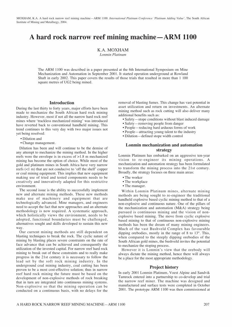
Theory of disc cuttingMechanical rock failure is a complex process influenced bynearly all rock physical and geological rock properties. Thedominant mode of failure is still the subject of muchresearch. One aspect shared by all the theories is theexistence of a zone of highly crushed rock material beneaththe cutter tip prior to chipping. As the cutter penetrates therock, a pressure bulb or crushed zone is formed due to theextremely high stresses generated in the rock under the tipof the cutter. The pressure in the crushed zone causestensile cracks to initiate and propagate into the rock mass. Ifthe stresses developed in the crushed zone are sufficientlyhigh, one or more cracks extend far enough to reach one ofthe tensile cracks developed from an adjacent cut, oralternatively a free face. In conventional disc cutting, rockfailure is in the form of chipping. Figure 1 shows this
process. In undercutting the crack propagation is to a freeface and rock fragments generated are substantially larger.
Narrow reef miner’s specificationEvaluation of the initial results from the pre-constructionphase led to the conclusion that the reef miner should havethe following generalized specifications:
• All the cutting discs would be mounted in the samecutting plane
• The reef would be cut in an undercutting mode, thusminimizing the power and cutting forces andmaximizing the chip sizes
• The effective undercutting depth was estimated to bebetween 50 and 60 mm
• Machine stability and stiffness was essential, thus,- the machine must be staked while cutting,- the cutter boom must be as short and stiff aspossible,
• The machine will not be fitted with crawlers and willwalk in the stope using its staking system
• The machine must be capable of cutting its own entryinto the stope
• The machine should excavate the maximum amount ofreef from a single set-up
• The machine in operation must be flexible enough tofollow the major reef undulations
• All rock cuttings must be removed from the immediatecutting area and then transported out of the stope.
Figure 1. Theoretical rock breaking process for conventional disc cutting
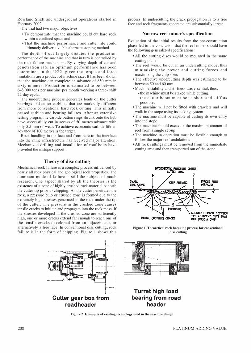
Figure 2. Examples of existing technology used in the machine design
A HARD ROCK NARROW REEF MINING MACHINE—ARM 1100 209
Additional features of the narrow reef minerThis generalized specification was fleshed out and the reefminer conceived is shown in Figure 3 and has the followingmain advantages:
• The machine design was simple in concept and madeuse of tried and tested components
• The machine was easy to automate and this had alreadybeen done with other coal mining machines
• The machine consists of easily maintainablecomponents with most of the main functions beingdriven by hydraulic cylinders
• Most importantly, because the total system is simpleand flexible, the machine can be accommodated in awide variety of mining layouts.
Underground trial
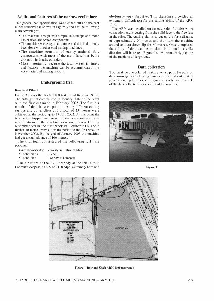
Rowland |ShaftFigure 3 shows the ARM 1100 test site at Rowland Shaft.The cutting trial commenced in January 2002 on 25 Levelwith the first cut made in February 2002. The first sixmonths of the trial was spent on testing different cuttingset-ups and cutter discs and a total of 25 metres wereachieved in the period up to 17 July 2002. At this point thetrial was stopped and new cutters were ordered andmodifications to the machine were undertaken. Cuttingrecommenced in the first week of October 2002 and afurther 40 metres were cut in the period to the first week inNovember 2002. By the end of January 2003 the machinehad cut a total advance of 100 metres.
The trial team consisted of the following full-timepersonnel:
• Artisan/operator - Western Platinum Mine• Technicians - VAB • Technician - Sandvik Tamrock
The structure of the UG2 orebody at the trial site isLonmin’s deepest, a UCS of ±120 Mpa, extremely hard and
obviously very abrasive. This therefore provided anextremely difficult test for the cutting ability of the ARM1100.
The ARM was installed on the east side of a raise-winzeconnection and is cutting from the solid face to the free facein the raise. The cutting plan is to cut up-dip for a distanceof approximately 70 metres and then turn the machinearound and cut down-dip for 80 metres. Once completed,the ability of the machine to take a blind cut in a strikedirection will be tested. Figure 6 shows some early picturesof the machine underground.
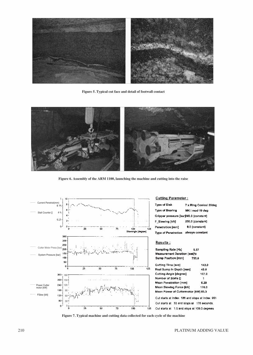
Data collectionThe first two weeks of testing was spent largely ondetermining best slewing forces, depth of cut, cutterpenetration, cycle times, etc. Figure 7 is a typical exampleof the data collected for every cut of the machine.
Figure 4. Rowland Shaft ARM 1100 test venue
Figure 3
PLATINUM ADDING VALUE210
Figure 5. Typical cut face and detail of footwall contact
Figure 6. Assembly of the ARM 1100, launching the machine and cutting into the raise
Figure 7. Typical machine and cutting data collected for each cycle of the machine
Current Penetrat(mm)
Stall Counter []
Cutter Motor Press [bar]
180
150
120
90
60
30
0
System Pressure [bar]
Power Cuttermotor [kW]
FSlew [kN]
211
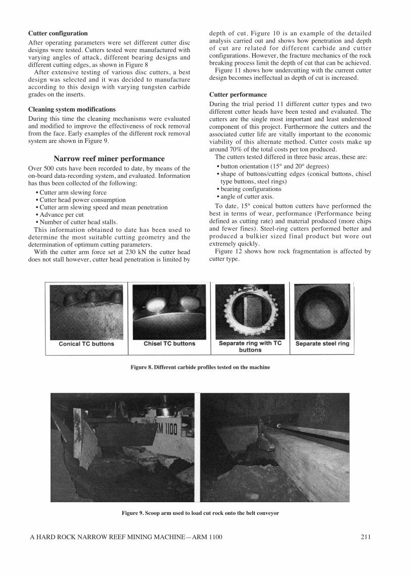
Cutter configurationAfter operating parameters were set different cutter discdesigns were tested. Cutters tested were manufactured withvarying angles of attack, different bearing designs anddifferent cutting edges, as shown in Figure 8
After extensive testing of various disc cutters, a bestdesign was selected and it was decided to manufactureaccording to this design with varying tungsten carbidegrades on the inserts.
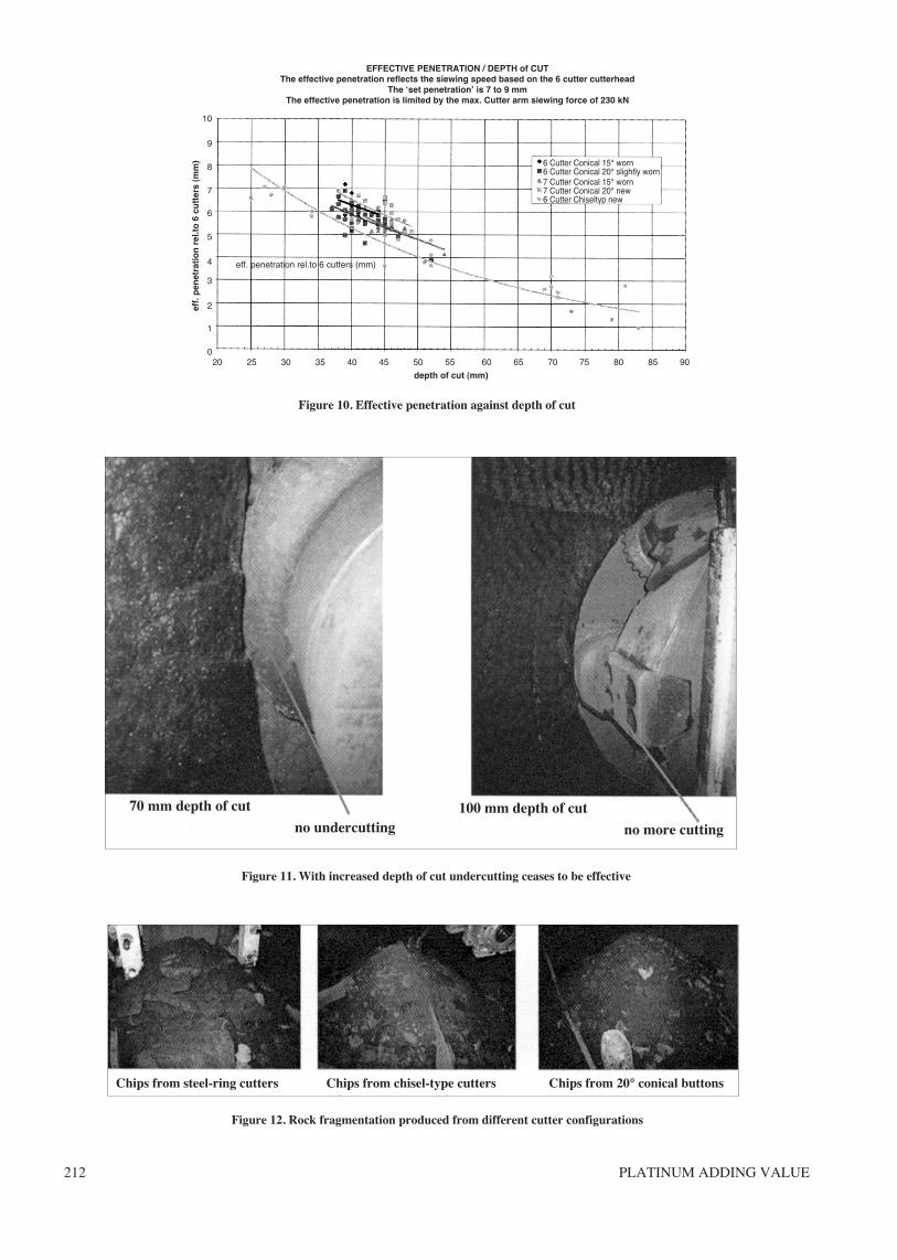
Cleaning system modificationsDuring this time the cleaning mechanisms were evaluatedand modified to improve the effectiveness of rock removalfrom the face. Early examples of the different rock removalsystem are shown in Figure 9.
Narrow reef miner performanceOver 500 cuts have been recorded to date, by means of theon-board data-recording system, and evaluated. Informationhas thus been collected of the following:
• Cutter arm slewing force• Cutter head power consumption• Cutter arm slewing speed and mean penetration• Advance per cut• Number of cutter head stalls.
This information obtained to date has been used todetermine the most suitable cutting geometry and thedetermination of optimum cutting parameters.
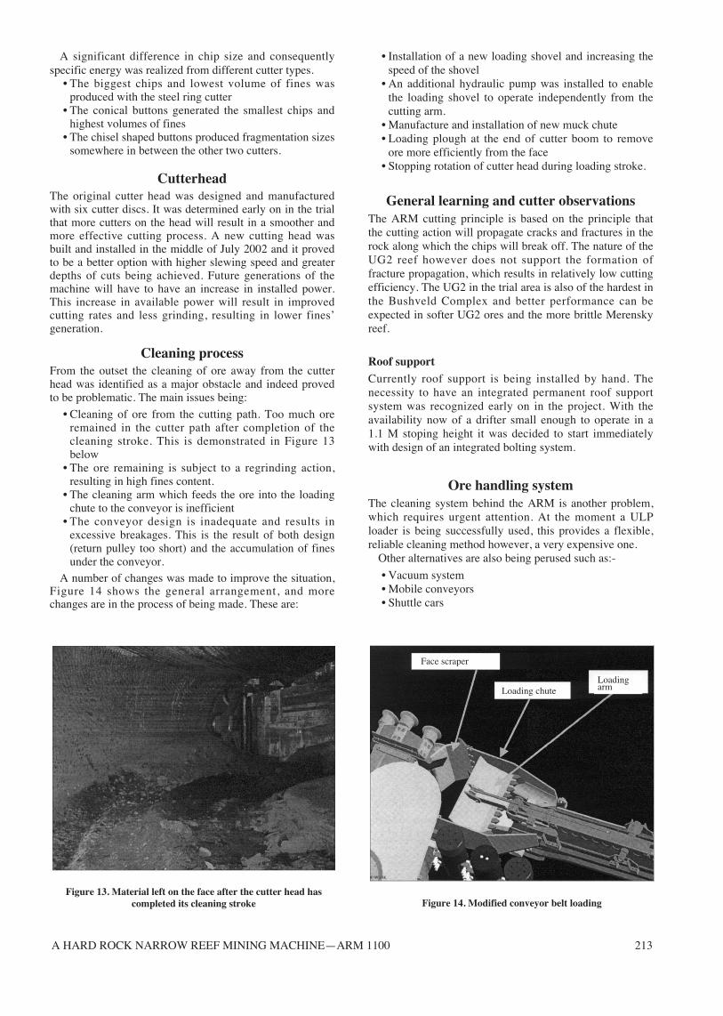
With the cutter arm force set at 230 kN the cutter headdoes not stall however, cutter head penetration is limited by
depth of cut. Figure 10 is an example of the detailedanalysis carried out and shows how penetration and depthof cut are related for different carbide and cutterconfigurations. However, the fracture mechanics of the rockbreaking process limit the depth of cut that can be achieved.
Figure 11 shows how undercutting with the current cutterdesign becomes ineffectual as depth of cut is increased.
Cutter performanceDuring the trial period 11 different cutter types and twodifferent cutter heads have been tested and evaluated. Thecutters are the single most important and least understoodcomponent of this project. Furthermore the cutters and theassociated cutter life are vitally important to the economicviability of this alternate method. Cutter costs make uparound 70% of the total costs per ton produced.
The cutters tested differed in three basic areas, these are:
• button orientation (15° and 20° degrees)• shape of buttons/cutting edges (conical buttons, chisel
type buttons, steel rings)• bearing configurations• angle of cutter axis.
To date, 15° conical button cutters have performed thebest in terms of wear, performance (Performance beingdefined as cutting rate) and material produced (more chipsand fewer fines). Steel-ring cutters performed better andproduced a bulkier sized final product but wore outextremely quickly.
Figure 12 shows how rock fragmentation is affected bycutter type.
Figure 8. Different carbide profiles tested on the machine
Figure 9. Scoop arm used to load cut rock onto the belt conveyor
A HARD ROCK NARROW REEF MINING MACHINE—ARM 1100
PLATINUM ADDING VALUE212
Figure 10. Effective penetration against depth of cut
Figure 11. With increased depth of cut undercutting ceases to be effective
Figure 12. Rock fragmentation produced from different cutter configurations
Chips from steel-ring cutters Chips from chisel-type cutters Chips from 20° conical buttons
70 mm depth of cut
no undercutting100 mm depth of cut
no more cutting
EFFECTIVE PENETRATION / DEPTH of CUTThe effective penetration reflects the siewing speed based on the 6 cutter cutterhead
The ‘set penetration’ is 7 to 9 mmThe effective penetration is limited by the max. Cutter arm siewing force of 230 kN
10
9
8
7
6
5
4
3
2
1
020 25 30 35 40 45 50 55 60 65 70 75 80 85 90
depth of cut (mm)
6 Cutter Conical 15° worn6 Cutter Conical 20° slightly worn7 Cutter Conical 15° worn7 Cutter Conical 20° new6 Cutter Chiseltyp new
eff. penetration rel.to 6 cutters (mm)
eff.
pen
etra
tio
n r
el.t
o 6
cu
tter
s (m
m)
A HARD ROCK NARROW REEF MINING MACHINE—ARM 1100 213
Figure 13. Material left on the face after the cutter head hascompleted its cleaning stroke Figure 14. Modified conveyor belt loading
Face scraper
Loading chuteLoadingarm
A significant difference in chip size and consequentlyspecific energy was realized from different cutter types.
• The biggest chips and lowest volume of fines wasproduced with the steel ring cutter
• The conical buttons generated the smallest chips andhighest volumes of fines
• The chisel shaped buttons produced fragmentation sizessomewhere in between the other two cutters.
CutterheadThe original cutter head was designed and manufacturedwith six cutter discs. It was determined early on in the trialthat more cutters on the head will result in a smoother andmore effective cutting process. A new cutting head wasbuilt and installed in the middle of July 2002 and it provedto be a better option with higher slewing speed and greaterdepths of cuts being achieved. Future generations of themachine will have to have an increase in installed power.This increase in available power will result in improvedcutting rates and less grinding, resulting in lower fines’generation.
Cleaning processFrom the outset the cleaning of ore away from the cutterhead was identified as a major obstacle and indeed provedto be problematic. The main issues being:
• Cleaning of ore from the cutting path. Too much oreremained in the cutter path after completion of thecleaning stroke. This is demonstrated in Figure 13below
• The ore remaining is subject to a regrinding action,resulting in high fines content.
• The cleaning arm which feeds the ore into the loadingchute to the conveyor is inefficient
• The conveyor design is inadequate and results inexcessive breakages. This is the result of both design(return pulley too short) and the accumulation of finesunder the conveyor.
A number of changes was made to improve the situation,Figure 14 shows the general arrangement, and morechanges are in the process of being made. These are:
• Installation of a new loading shovel and increasing thespeed of the shovel
• An additional hydraulic pump was installed to enablethe loading shovel to operate independently from thecutting arm.
• Manufacture and installation of new muck chute• Loading plough at the end of cutter boom to remove
ore more efficiently from the face• Stopping rotation of cutter head during loading stroke.
General learning and cutter observationsThe ARM cutting principle is based on the principle thatthe cutting action will propagate cracks and fractures in therock along which the chips will break off. The nature of theUG2 reef however does not support the formation offracture propagation, which results in relatively low cuttingefficiency. The UG2 in the trial area is also of the hardest inthe Bushveld Complex and better performance can beexpected in softer UG2 ores and the more brittle Merenskyreef.
Roof support
Currently roof support is being installed by hand. Thenecessity to have an integrated permanent roof supportsystem was recognized early on in the project. With theavailability now of a drifter small enough to operate in a 1.1 M stoping height it was decided to start immediatelywith design of an integrated bolting system.
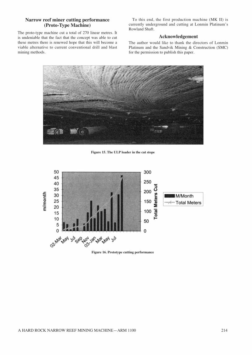
Ore handling systemThe cleaning system behind the ARM is another problem,which requires urgent attention. At the moment a ULPloader is being successfully used, this provides a flexible,reliable cleaning method however, a very expensive one.
Other alternatives are also being perused such as:-
• Vacuum system• Mobile conveyors• Shuttle cars
A HARD ROCK NARROW REEF MINING MACHINE—ARM 1100 214
Figure 15. The ULP loader in the cut stope
Figure 16. Prototype cutting performance
Narrow reef miner cutting performance(Proto-Type Machine)
The proto-type machine cut a total of 270 linear metres. Itis undeniable that the fact that the concept was able to cutthese metres there is renewed hope that this will become aviable alternative to current conventional drill and blastmining methods.
To this end, the first production machine (MK II) iscurrently underground and cutting at Lonmin Platinum’sRowland Shaft.
AcknowledgementThe author would like to thank the directors of LonminPlatinum and the Sandvik Mining & Construction (SMC)for the permission to publish this paper.