Embed Size (px)
Citation preview

PA G E 9
A Guideline Protocol for the Assessment of Aortic Stenosis, Including Recommendations for Echocardiography in Relation to Transcatheter Aortic Valve Implantation
From the British Society of Echocardiography Education CommitteeBushra Rana (Lead Author)
Richard Steeds, Chair
Hollie Brewerton
Alison Carr
Richard Jones
Prathap Kanagala
Daniel Knight
Thomas Mathew
Kevin O’Gallagher
Dave Oxborough
Liam Ring
Julie Sandoval
Martin Stout
Gill Wharton
Richard Wheeler
Review and information relating to this document has been provided by John Chambers, Mark Monaghan, Derek Chin, Navroz Masani, and Simon Ray.
1. Introduction1. 1 The BSE Education Committee has recently published a minimum dataset for a standard adult transthoracic echocardiogram, available on-line at www.bsecho.org. This document specifically states that the minimum dataset is usually only sufficient when the echocardiographic study is entirely normal. The aim of the Education Committee is to publish a series of appendices to cover specific pathologies to support this minimum dataset.
1.2 The intended benefits of such supplementary recommendations are to:
• Support cardiologists and echocardiographers to develop local protocols and quality control programs for adult transthoracic study;
• Promote quality by defining a set of descriptive terms and measurements, in conjunction with a systematic approach to performingand reporting a study in specific disease-states;
• Facilitate the accurate comparison of serial echocardiograms performed in patients at the same or different sites.
1.3. This document gives recommendations for the image and analysis dataset required in patients being assessed for aortic stenosis.Echocardiography has become the standard method for evaluating aortic stenosis severity. Other methods such as cardiaccatheterisation are not routine except where the data is non-diagnostic or discrepant with clinical data.
Although the standard method for evaluation of aortic stenosis, there are a number of situations in which data fromechocardiography may at first appear inconsistent. If dealt with in a structured fashion, many of these inconsistencies may bereconciled and important information gained to assist patient management. A structured approach is outlined in Appendix 1.
Management of aortic stenosis has been altered by the availability of transcatheter aortic implantation as an alternative treatment forthose at high risk or excluded from conventional surgery. Given the central role of echocardiography before, during and afterimplantation of these devices, there is a further Appendix (2) relating specifically to assessment for transcatheter aortic valveimplantation.
1.4. The views and measurements are supplementary to those outlined in the minimum dataset and are given assuming a full studywill be performed in all patients.
1.5 When the condition or acoustic windows of the patient prevent the acquisition of one or more components of the supplementaryDataset, or when measurements result in misleading information (e.g. off-axis measurements) this should be stated.
1.6 This document is a guideline for echocardiography in the assessment of aortic stenosis and will be up-dated in accordance withchanges directed by publications or changes in practice.

PA G E 10
Measurement
Cusps viewed1
Cusp anatomy
Appearance
Mobility
Thickening
Calcification
MeasurementsLVOT
Annulus
Aortic RootAscending aorta
Explanatory note
NCC/RCC
Systolic doming/asymmetric closure line(?bicuspid).Commissure fusion (?rheumatic).
Degree of restrictiongrade as: mild =restricted motion at basal1/3 adjacent to hinge only, moderate=base+ body (middle third), severe=base+body+free edge (distal 1/3)
Mild/moderate/severe
Describe severity: mild/mod/severe mild = small isolated spots ; moderate =multiple larger spots; severe = heavily calci-fied, extensive thickening and calcification ofall cusps.2Location and extent:-AV cusps- free edge, body, base (point ofinsertion).-LVOT, annulus, aortic wall, aortic root,ascending aorta.
As per min dataset, performed at similarlevel as LVOT PW Doppler velocity traceobtained from either 5CV or 3CV, see below.[Zoom mode, mid systole, min 3 beats (5 ifAF) measure inner edge to inner edge]
Zoom mode; Measure from cusp hingepoints (at point of cusp insertion into wall),ignoring all calcification. Measure maximumdimension where seen best in cardiac cycle(see notes 3)
Try to obtain symmetrical aortic root sinuseswith ascending aorta not foreshortened.Measure maximum diameter where seenbest in cardiac cycle. Inner edge-inner edge(blood tissue interface).
Modality
2D
VIEW
PLAX
Bicuspid AV with asymmetric closure line
Image
tricuspid AV with heavily calcified cusps

PA G E 11
(AV level, above, below)AR jet
Cusps viewed
Cusp anatomy Mobility/thickening/cal-cification
Number of cusps
Calcification
AV level
LVOTAortic RootAscending aorta
2D planimetry
Turbulent flow(AV level, above, below)AR jet
Cusp anatomy Mobility/thickening/cal-cification
LVOT VTI(NOTE: can also beperformed in 3CV)
Ensure turbulent flow as expected at valvelevel. If below ?LVOT obstruction
(See regurgitation quantification guidelines)
NCC/RCC/LCC
(as above)
Bicuspid (elliptical systolic orifice with 2commissures) 4If possible, state which leaflets are not sepa-rated.
DistributionNote: location and extent(as above)
AV cusps- free edge, body, insertion
Sweep above and below AV -Protrusion ofcalcification into outflow tract below level ofannulus.-Aortic wall, extension into lumen, size.
Not recommended as routine measure1,since ‘effective’ rather than ‘anatomic’ ori-fice is primary predictor of outcome.-Acceptable alternative when Doppler esti-mation is unreliable (e.g coexisting LVOTobstruction) -If performed must ensure minimum orificeidentified, i.e. usually at the tips. 3D willassist in optimising this measurement
As above
generalobservation
Sample volume positioned just at level of AVannulus and moved carefully into the LVOT ifnecessary, until laminar flow curve obtainedi.e. smooth velocity curve with narrow band,well defined peak. (Typically 0.5-1.0cm fromAV annulus in calcific AS; AV annulus level inbicuspid AS). Trace around outer signal
ColourDoppler
2D
ColourDoppler
2D
Doppler PW
PSAX,AV level
A5CV
No turbulent flow seen below or above the AVlevel
tricuspid AV
Bicuspid AV with elliptical orifice
}

PA G E 12
AV Vmax/VTI
Turbulent flow(AV level, above, below)AR jet
Cusps viewed
Cusp anatomy Mobility/appearance/calcification
If better alignmentwith flow across AV,consider additionalmeasurements, asabove
Turbulent flow(AV level, above, below)AR jet
Maximum velocity obtained should bereported. Trace around outer signal. Repeatin multiple acoustic windows in order todocument maximum velocity (see below).Shape of signal useful in ∆∆-severe stenosis: rounded shape, peak in midsystole-mild stenosis: triangular, peak in early sys-tole
Measurements:Max AV velocity Mean AV gradientAVA (Continuity equation)
Additional useful measurements:VTI ratio or velocity ratio (dimensionlessindex)5Severe < 0.25
As above
NCC/RCC
generalObservation
as above
CW
ColourDoppler
2D
Doppler
ColourDoppler
A3CV
Aortic stenosis with no LVOT obstruction; no tur-bulent flow in outflow tract
Turbulent flow seen within outflow tract; LVOTobstruction.
}

PA G E 13
AV in short axis
Hunt for maximum AVvelocity
See PSAX section
Document in report which window maxi-mum velocity obtained
2D
CW
SC view(if poor PSAX)
Blind Doppler
R. parasternal(as shown)
Also consider:ApicalSuprasternal Subcostal
AS severity
AS aetiology
AR severity
Aortic dimensions
LVEFLV hypertrophy
LA size
RV size and function
TR
PAP
Other valve disease
BP recordedBSA recorded
Possible TOE indications
Max velocity, mean gradient, AVA(report window where maximum velocity obtained). When AV parameters are discordant see appendix 1
Where possible comment on most likely cause (e.g. rheumatic, degenerative, congenital/bicuspid)
See regurgitation quantification guidelines (consider effects on velocity measurements)
Dilatation associated with AVD/bicuspid.. May indicate need for early surgery. Also exclude aortic coarc-tation.
See chamber quantification guidelines
Affects operative risk
Severity
Affects operative risk and prognosis
?Mitral valve surgery in addition MR, functional versus degenerative disease
Index values as appropriate
Indeterminate AS severity poor imagingAV annulus sizing/TAVI assessment (see appendix 2)
General considerations

Appendix 1: DISCREPANCIES IN PARAMETERS OF AORTIC STENOSIS SEVERITY
Discrepancies in aortic valve (AV) parameters may occur in up to 25% of cases. The evidence base is not complete. However, the BSEEducation committee would like to provide guidance in this clinical scenario. The following is a possible approach to imaging suchcases.
Emphasis is placed on assessment of AV anatomy and cusp mobility. Colour flow imaging can help judge approximate orifice size.TOE may be indicated if doubt remains.
Discrepancies in these parameters can be broadly divided into three categories. Before proceeding, ensure you are satisfied the meas-urements are accurate. Run through the checklist below. Then make some additional calculations where relevant and decide whichcategory the discrepancies in AV parameters belong (1-3).
Therefore:
A. Checklist: ensure measurements correct
- LVOT diameter: compare with previous, is LVOT measurement accurate? Does resolution allow accurate measurement? Sigmoid sep-tum causing LVOT to be non-circular? Remember small error is LVOT diameter result in moderate AS becoming severe on calculationse.g. diameter 2.1= AVA 1.1cm2 ; 1.9= AVA 0.9cm2 ; while diameter 1.8= AVA 0.8cm2
- LVOT PW Doppler: has the sample volume been placed at correct level and correct distance from AV, where laminar flow isobtained?
- AV CW Doppler: is AV CW Doppler profile consistent? Ensure not mitral regurgitation signal!!
- Dimensionless index (DI) or velocity ratio: severe <0.25. Although a useful additional measure, by removing the potential inaccura-cies of LVOT measurement, remember that it ignores inaccuracies due to abnormal LVOT anatomy e.g. isolated basal hypertrophy.Hence, its particular use is in the setting of serial measurements within the same individual or when assessing prosthetic valves,especially where the size of the valve is unknown.
B. Calculate additional parameters where relevant6
- AVA indexed for BSA (AVAi); severe <0.6cm2/m2
- SV indexed for BSA (SVi); low flow <35ml/m2
Either by continuity eqn / LV volumes 2D or 3D
- Impedance (valvulo-arterial), Zva significantly increased> 5.5mmHg/ml/m2
Reflects the global LV haemodynamic load, i.e. the double afterload on LV from the stenosed AV and from the vascular system (sys-temic arterial compliance and systemic vascular resistance):
Zva calculated as = mean AVG + systolic BP
SVi
Degenerative aortic stenosis (AS) may be associated with a reduction in systemic arterial compliance due to rigid arterial vessels. Thisis clinically manifested as systolic hypertension. This additional arterial afterload results in underestimation of AS severity; a greaterproportion of such patients may not be referred appropriately and in a timely manner for surgery. This is typically seen in patientswith low flow-low gradient severe AS in the setting of normal LVEF or in patients with presumed moderate AS with symptoms.
C. Discrepancies 6-8 in these parameters can be broadly divided into three categories
1. AVA suggests severe AS, but max velocity and mean AV gradient (AVG) do not.
i.e. AVA <1.0 cm2
max velocity < 4.0 m/s
mean AVG < 40mmHg
a) Impaired LV function (LVEF <40%): differential diagnosis will either be
- truly severe AS or
- moderate (or less severe) AS with poor valve opening due to poor cardiac output
Step 1: Confirm measurements are correct (LVOT diameter, LVOT PWD, AV CWD)
Step 2: Ensure the anatomy of the AV correlates with severity (including degree of calcification and cusp mobility). Exclude concomi-tant mitral valve disease.
Step 3: Consider low dose dobutamine stress echocardiography to determine severity of aortic stenosis1,7
PA G E 14
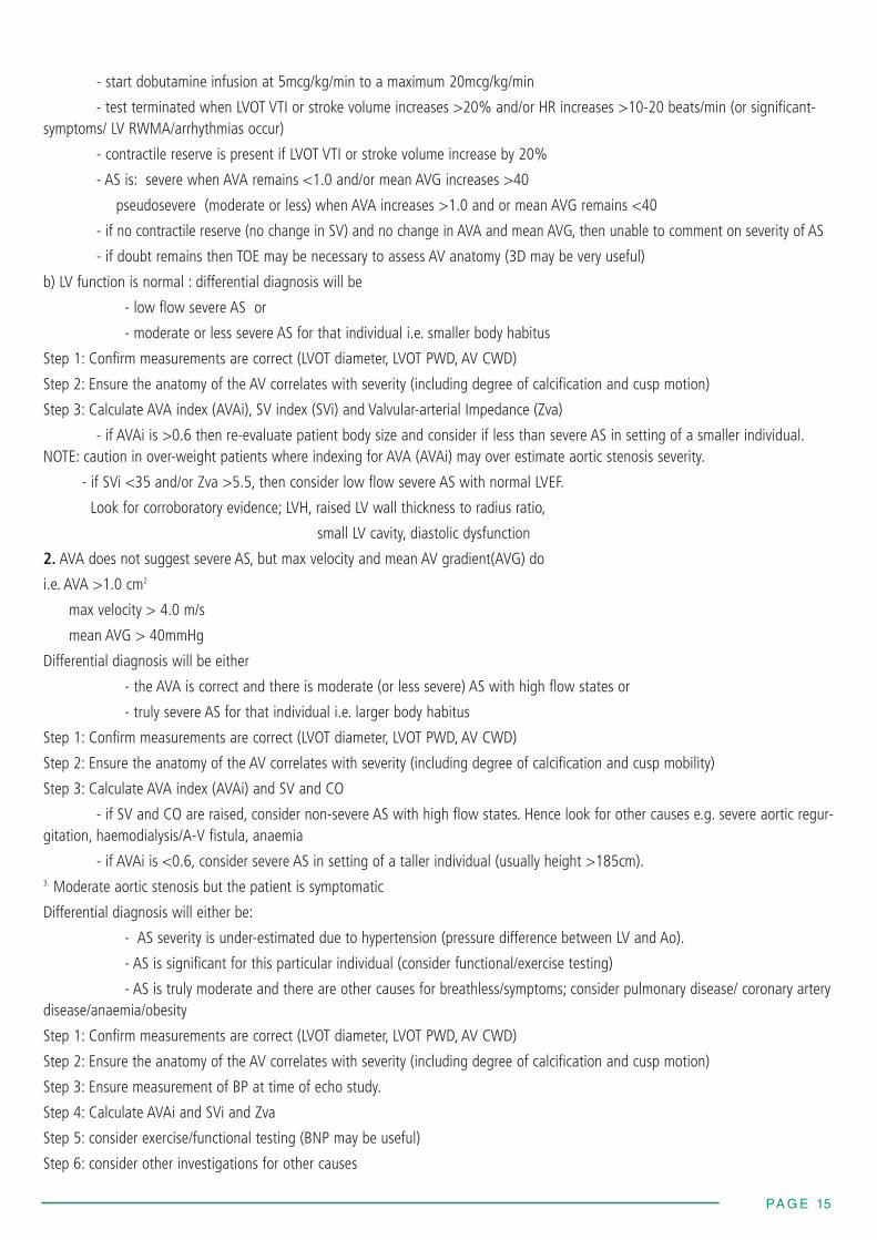
- start dobutamine infusion at 5mcg/kg/min to a maximum 20mcg/kg/min
- test terminated when LVOT VTI or stroke volume increases >20% and/or HR increases >10-20 beats/min (or significant-symptoms/ LV RWMA/arrhythmias occur)
- contractile reserve is present if LVOT VTI or stroke volume increase by 20%
- AS is: severe when AVA remains <1.0 and/or mean AVG increases >40
pseudosevere (moderate or less) when AVA increases >1.0 and or mean AVG remains <40
- if no contractile reserve (no change in SV) and no change in AVA and mean AVG, then unable to comment on severity of AS
- if doubt remains then TOE may be necessary to assess AV anatomy (3D may be very useful)
b) LV function is normal : differential diagnosis will be
- low flow severe AS or
- moderate or less severe AS for that individual i.e. smaller body habitus
Step 1: Confirm measurements are correct (LVOT diameter, LVOT PWD, AV CWD)
Step 2: Ensure the anatomy of the AV correlates with severity (including degree of calcification and cusp motion)
Step 3: Calculate AVA index (AVAi), SV index (SVi) and Valvular-arterial Impedance (Zva)
- if AVAi is >0.6 then re-evaluate patient body size and consider if less than severe AS in setting of a smaller individual.NOTE: caution in over-weight patients where indexing for AVA (AVAi) may over estimate aortic stenosis severity.
- if SVi <35 and/or Zva >5.5, then consider low flow severe AS with normal LVEF.
Look for corroboratory evidence; LVH, raised LV wall thickness to radius ratio,
small LV cavity, diastolic dysfunction
2. AVA does not suggest severe AS, but max velocity and mean AV gradient(AVG) do
i.e. AVA >1.0 cm2
max velocity > 4.0 m/s
mean AVG > 40mmHg
Differential diagnosis will be either
- the AVA is correct and there is moderate (or less severe) AS with high flow states or
- truly severe AS for that individual i.e. larger body habitus
Step 1: Confirm measurements are correct (LVOT diameter, LVOT PWD, AV CWD)
Step 2: Ensure the anatomy of the AV correlates with severity (including degree of calcification and cusp mobility)
Step 3: Calculate AVA index (AVAi) and SV and CO
- if SV and CO are raised, consider non-severe AS with high flow states. Hence look for other causes e.g. severe aortic regur-gitation, haemodialysis/A-V fistula, anaemia
- if AVAi is <0.6, consider severe AS in setting of a taller individual (usually height >185cm).3. Moderate aortic stenosis but the patient is symptomatic
Differential diagnosis will either be:
- AS severity is under-estimated due to hypertension (pressure difference between LV and Ao).
- AS is significant for this particular individual (consider functional/exercise testing)
- AS is truly moderate and there are other causes for breathless/symptoms; consider pulmonary disease/ coronary arterydisease/anaemia/obesity
Step 1: Confirm measurements are correct (LVOT diameter, LVOT PWD, AV CWD)
Step 2: Ensure the anatomy of the AV correlates with severity (including degree of calcification and cusp motion)
Step 3: Ensure measurement of BP at time of echo study.
Step 4: Calculate AVAi and SVi and Zva
Step 5: consider exercise/functional testing (BNP may be useful)
Step 6: consider other investigations for other causes
PA G E 15

PA G E 16
Measurement
AnatomyDistribution of calcifi-cation
AV
LVOTAortic RootAscending aorta
Coronary ostia
Measurements:Annulus
Aortic RootAscending aorta
Explanatory note
Number of cusps; bicuspid may be a relativecontra-indication
Protrusion of calcification into outflow tractbelow level of annulus; above in Ao root,aortic wall, extension into lumen,
LMS/RCA-could calcification impinge oncoronary ostia?
Aim for symmetrical aortic root sinuses withascending aorta not foreshortened
Measure maximum diameter where seenbest in cardiac cycle. Measure from cusphinge points (at point of cusp insertion intowall) and ignoring calcification May need to change level of probe withinoesophagus or rotated to show RCC inser-tion point (if covered by echo drop out fromheavy calcification)
EDWARDS 23: 18-22mm 26: 21-25mm 29: 24-27mm
CORVALVE 23: 17- 20mm26: 20-23mm 29: 23-27mm31: 26-29mm
Measure maximum diameter where seenbest in cardiac cycle. Inner edge-inner edge(blood tissue interface)EDWARDS although no specific measure-ments given consideration should be givento smaller aortic root as increased risk forcomplications e.g root rupture CORVALVE 26:SoV width >27mm
SoV height >15mmSTJ ≤40mm
Modality
2D
VIEWGuide angle
SAX AV (guide 40-600)
Sweep aboveand below AV
LAX AV(guide 120-1500)
APPENDIX 2: TOE for TAVI assessment : specific considerations additional to TOE minimum datasetPlease note: information on current TAVI valves is given, however new products are continually under development and the readershould consult with company literature with regards to current valve sizes and annulus sizes.
Tricuspid AV
Bicuspid AV
Examples of AV annulus measurements
Image

PA G E 17
Septal bulge
Calcification
AnatomyLVOTAV aorta
29 AND 31: SoV width >29mm SoV height >15mmSTJ ≤43mm
Measure height from peak bulge of septum(in systole) to AV annulus levelEDWARDS ≥8mm requiredCOREVALVE septum dimension should be<17mm ; if > 17mm at increased risk ofcomplications (in diastole)
Describe distribution, location and extent
AV cusps- free edge, body, insertion point,commissures
Aortic wall- include LVOT, level of annulus,aortic root, ascending aorta
Specific(i) solid sheet extending from free edge allthe way into annulus insertion into wall –this suggests rigid cusp with risk that cuspwill not hinge open.(ii) large ‘lumps’ of calcificationin LVOT (with tendency to displace AV pros-thesis upwards during deployment) or inaortic root (with tendency to displace AVprosthesis downwards during deployment).
Further clarify number of cusps.Distribution of calcification. above/belowand at valve levelSymmetry of annulus useful predictor of riskof paravalvular AR
3DLive/zoom modeand/orx-plane
3D imagingmay offeruseful addi-tional infor-mationCan be per-formed in SAXand LAXplanes whereAV and sur-rounding struc-tures (LVOT/Ao)are seen
Solid ‘sheet’ of calcification RCC of AV

PA G E 18
Measurements:AV annulusUsing 3D is possiblehowever please notereference measurementis 2D long axis view(usually TOE).
Coronary ostia height
Use multiplane reconstruction in to facilitatemultiple annulus measurements (not justsaggital and coronal planes). Use maximumand minimum measurements to obtain anaverage annulus size. If the annulus is tooelliptical, this is a relative contra-indication.,suggested guide EDWARDS if > 1.2-1.3:1then increased risk of complications
Measure level of RCA and LMS ostia fromannulus
EDWARDS ≥10mmCORVALVE ≥14mm
Full-vol-ume or3DLive/zoommode
References
1. Baumgartner H et al. European Journal of Echocardiography (2009) 10; 1–25. Echocardiographic assessment of valve stenosis: EAE/ASE recommendations forclinical practice.
2. Rosenhek et al. N Engl J Med (2000) 343; 611-7. Predictors of outcome in asymptomatic, severe aortic stenosis. Calcification of the aortic valve is scored asfollows: 1, no calcification; 2, mildly calcified (small isolated spots); 3, moderately calcified (multiple larger spots); and 4, heavily calcified (extensive thickening andcalcification of all cusps).
3. Measure widest diameter at any point in cardiac cycle. There is no published evidence as to the ideal time point in the cardiac cycle when measurement should bemade.
4. Schaefer et al. Heart (2008) 94(12); 1634-8. The bicuspid aortic valve: an integrated phenotypic classification of leaflet morphology and aortic root shape.
5. Good correlation seen between velocity ratio and velocity time integral ratio. Hence either may be used
6. Dumesnil JG et al. Eur Heart J (2010) 31;281-9. Paradoxical low flow and/or low gradient severe aortic stenosis despite preserved left ventricular ejection fraction: implications for diagnosis and treatment.
7. Chambers J. Heart (2006) 92;554-8. Low gradient, low flow aortic stenosis.
8. Chambers J. Eur J Echo (2009) 10:i11-19. Aortic stenosis.
Bicuspid AV
Full volume 3D image showing relationship ofAV to surrounding structures
Example of coronary ostia measurement usingQLab