Embed Size (px)
Citation preview
Copyright© 2020 GAF ▪ 1 Campus Drive Parsippany, NJ 07054 ▪ www.gaf.com
A Guide to Using ASCE 7-16 For EverGuard® TPO/PVC Mechanically Attached and
Drill-TecTM RhinoBond® Roofing Systems
Prepared by GAF Technical Services October 2020

Copyright© 2020 GAF ▪ 1 Campus Drive Parsippany, NJ 07054 ▪ www.gaf.com
1
ASCE
7-1
6 Gu
ide
Pub
lishe
d 10
/ 202
0
Table of Contents Page Introduction 2
About GAF 2 ASCE 7 2 Important Considerations 3
Step-by-step Procedure Step 1 – Determine the Applicable Building Code 4 Step 2 – Locate Design Wind Uplift Pressures 4 Step 3 – Identify the Design Method Used 5 Step 4 – Apply a Safety Factor 5 Step 5 – Select a Wind Rated Roofing System 5 Step 6 – Determine the Wind Zone Layout 8
Rectangular Roof Plan Examples 9 Non-rectangular Roof Plan Example 12 Courtyard Example 13 Roof Zone 1’ 14 Parapets ≥ 3 feet 14 Lookup Tables with 0.6h and 0.2h Calculations 14
Application Considerations for Roof Zones 2 and 3 18
Performance-based 18 Prescriptive Enhancement 18
Conventional Mechanically Attached Roofing Systems 19 Method A: Standard Picture Framing 20 Method B: Modified Picture Framing 22 Method C: Full Size and Half Size Sheets with Intermediate Fastener Rows 24 Method D: Full Size Sheets with Intermediate Fastener Rows 29
Drill-TecTM RhinoBond Roofing Systems 34 Appendixes
Appendix A: ASCE 7 Comparison 36 Appendix B: FM 1-29 Prescriptive Enhancements for Perimeters and Corners 39 Appendix C: Roof Zone Layout Examples for a Non-rectangular Roof Plan 41
Conventional Mechanically Attached Roof Systems Examples 42 Drill TecTM RhinoBond® Roof Systems Examples 46

Copyright© 2020 GAF ▪ 1 Campus Drive Parsippany, NJ 07054 ▪ www.gaf.com
2
ASCE
7-1
6 Gu
ide
Publ
ished
10/
2020
Introduction
The purpose of this guide is to provide fundamental information on code requirements, wind design, how to navigate ASCE 7-16 when selecting appropriate roofing systems, and suggestions on roof system application. This guide is limited to: • 2016 edition of ASCE 7, “Minimum Design Loads and Associated Criteria for Buildings and Other
Structures” (ASCE 7-16). • Buildings with roof slopes less than 7 degrees (approximately 1½:12 roof slope). • Building heights less than 60 ft. • Mechanically attached and Drill-TecTM RhinoBond® roofing systems.
About GAF Founded in 1886, GAF is the largest roofing manufacturer in North America. As the industry leader, GAF proudly offers a comprehensive portfolio of award-winning, innovative roofing products for both steep-slope and commercial properties. Supported by an extensive national network of factory-certified contractors, GAF has built its reputation – and its success – on its steadfast commitment to Advanced Quality, Industry Expertise, and Solutions Made Simple.
GAF offers all major low-slope roofing technologies, including repair and maintenance products and roof restoration systems, as well as new roofing systems (BUR, modified bitumen, TPO, PVC, and liquid-applied roofing membranes). GAF has developed single-ply, asphaltic and liquid-applied membranes with excellent durability to meet the most rigorous industry standards.
For more information, visit www.gaf.com.
ASCE 7 ASCE 7, “Minimum Design Loads for Buildings and Other Structures” (ASCE 7) is a consensus standard developed and maintained by the American Society of Civil Engineers. It describes the means for determining dead, live, soil, flood, tsunami, snow, rain, atmospheric ice, earthquake, and wind loads, and their combinations for general structural design.
Three editions of ASCE 7 are used in the U.S., the 2005, 2010 and 2016. The 2016 edition has several significant changes that affect the wind design of roofing systems.
Roofing systems are considered Components and Cladding (C&C). The design procedures for C&C are located in Chapter 30, Wind Loads—Components and Cladding (C&C).

Copyright© 2020 GAF ▪ 1 Campus Drive Parsippany, NJ 07054 ▪ www.gaf.com
3
ASCE
7-1
6 Gu
ide
Pub
lishe
d 10
/ 202
0
The following design parameters are used to determine design wind uplift pressures:
• Roof slope (must be less than 7 degrees) • Building dimensions (width, length and height) • Basic wind speed, V • Risk Category (I, II, III or IV) • Exposure coefficient (B, C or D) • Topography factor, kzt • Wind directionality factor, kd • Ground elevation factor, ke
There are some noteworthy differences between the three ASCE 7 editions and they include: the wind speed maps, roof zones, enclosure classifications, external pressure coefficients, and the equation to calculate velocity pressures. See Appendix A for additional information on the differences between the 2005, 2010 and 2016 editions of ASCE 7. Important Considerations GAF manufactures and sells roofing materials and does not practice architecture or engineering. GAF is not responsible for the performance of its products when damage to its products is caused by such things as improper building design, construction flaws, or defects in workmanship. The design responsibility remains with the architect, engineer, roofing contractor, or owner. These guidelines should not be construed as being all-inclusive. Please consult your design professional for more information.
The guidelines contained herein are for information purposes only, and are not intended as a substitute for independent evaluation by the building owner or its consultants to determine with certainty whether a particular roofing system is suitable for a building. GAF makes no representation or warranty (express or implied) as to the suitability of its roofing systems for buildings.
Information contained in this Guide is presented in good faith and, to the best of GAF’s knowledge, does not infringe upon any patents, foreign or domestic.
Copyright© 2020 GAF ▪ 1 Campus Drive Parsippany, NJ 07054 ▪ www.gaf.com
4
ASCE
7-1
6 Gu
ide
Publ
ished
10/
2020
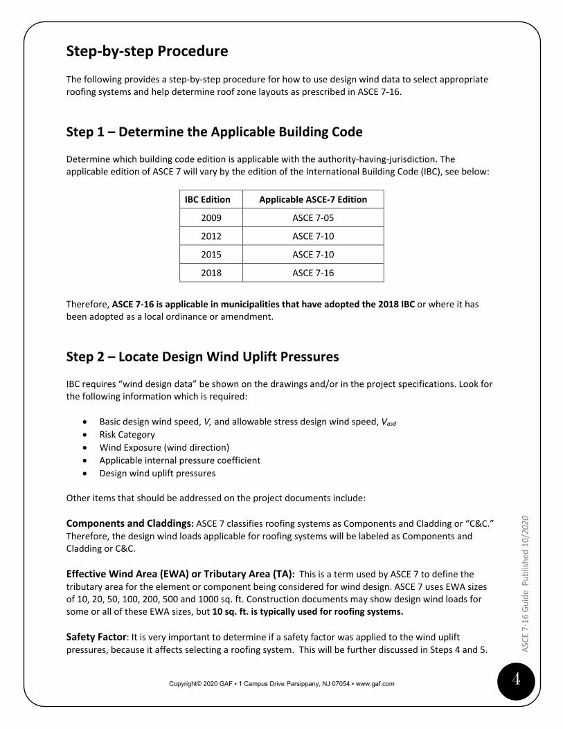
Step-by-step Procedure The following provides a step-by-step procedure for how to use design wind data to select appropriate roofing systems and help determine roof zone layouts as prescribed in ASCE 7-16.
Step 1 – Determine the Applicable Building Code Determine which building code edition is applicable with the authority-having-jurisdiction. The applicable edition of ASCE 7 will vary by the edition of the International Building Code (IBC), see below:
IBC Edition Applicable ASCE-7 Edition
2009 ASCE 7-05
2012 ASCE 7-10
2015 ASCE 7-10
2018 ASCE 7-16
Therefore, ASCE 7-16 is applicable in municipalities that have adopted the 2018 IBC or where it has been adopted as a local ordinance or amendment.
Step 2 – Locate Design Wind Uplift Pressures IBC requires “wind design data” be shown on the drawings and/or in the project specifications. Look for the following information which is required:
• Basic design wind speed, V, and allowable stress design wind speed, Vasd • Risk Category • Wind Exposure (wind direction) • Applicable internal pressure coefficient • Design wind uplift pressures
Other items that should be addressed on the project documents include: Components and Claddings: ASCE 7 classifies roofing systems as Components and Cladding or “C&C.” Therefore, the design wind loads applicable for roofing systems will be labeled as Components and Cladding or C&C. Effective Wind Area (EWA) or Tributary Area (TA): This is a term used by ASCE 7 to define the tributary area for the element or component being considered for wind design. ASCE 7 uses EWA sizes of 10, 20, 50, 100, 200, 500 and 1000 sq. ft. Construction documents may show design wind loads for some or all of these EWA sizes, but 10 sq. ft. is typically used for roofing systems. Safety Factor: It is very important to determine if a safety factor was applied to the wind uplift pressures, because it affects selecting a roofing system. This will be further discussed in Steps 4 and 5.
Copyright© 2020 GAF ▪ 1 Campus Drive Parsippany, NJ 07054 ▪ www.gaf.com
5
ASCE
7-1
6 Gu
ide
Pub
lishe
d 10
/ 202
0
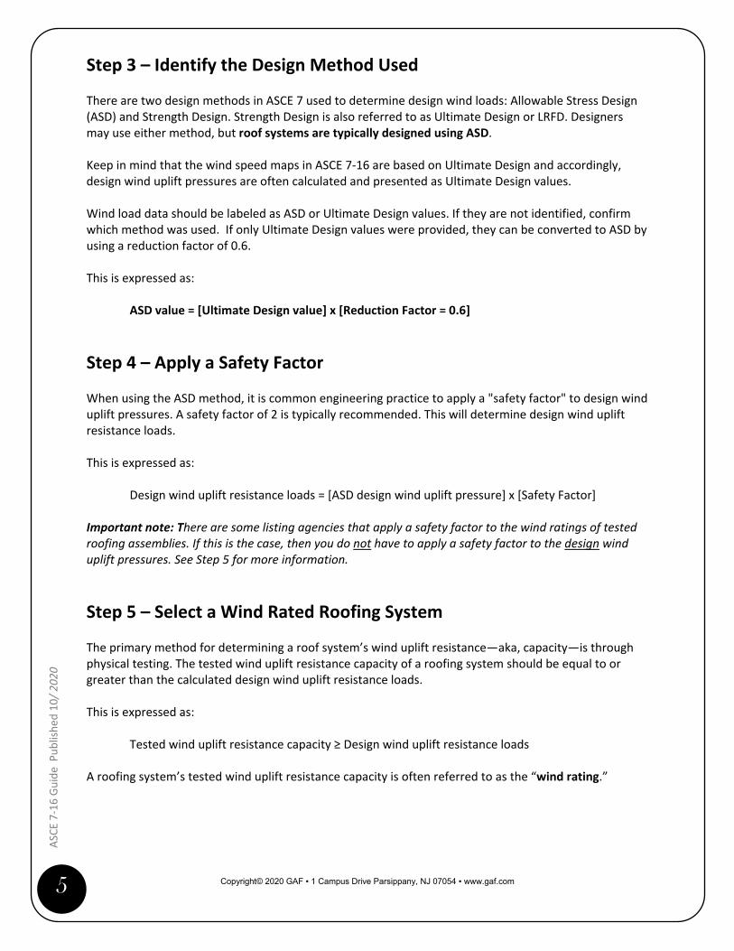
Step 3 – Identify the Design Method Used There are two design methods in ASCE 7 used to determine design wind loads: Allowable Stress Design (ASD) and Strength Design. Strength Design is also referred to as Ultimate Design or LRFD. Designers may use either method, but roof systems are typically designed using ASD. Keep in mind that the wind speed maps in ASCE 7-16 are based on Ultimate Design and accordingly, design wind uplift pressures are often calculated and presented as Ultimate Design values. Wind load data should be labeled as ASD or Ultimate Design values. If they are not identified, confirm which method was used. If only Ultimate Design values were provided, they can be converted to ASD by using a reduction factor of 0.6. This is expressed as:
ASD value = [Ultimate Design value] x [Reduction Factor = 0.6]
Step 4 – Apply a Safety Factor When using the ASD method, it is common engineering practice to apply a "safety factor" to design wind uplift pressures. A safety factor of 2 is typically recommended. This will determine design wind uplift resistance loads. This is expressed as:
Design wind uplift resistance loads = [ASD design wind uplift pressure] x [Safety Factor] Important note: There are some listing agencies that apply a safety factor to the wind ratings of tested roofing assemblies. If this is the case, then you do not have to apply a safety factor to the design wind uplift pressures. See Step 5 for more information.
Step 5 – Select a Wind Rated Roofing System The primary method for determining a roof system’s wind uplift resistance—aka, capacity—is through physical testing. The tested wind uplift resistance capacity of a roofing system should be equal to or greater than the calculated design wind uplift resistance loads. This is expressed as:
Tested wind uplift resistance capacity ≥ Design wind uplift resistance loads
A roofing system’s tested wind uplift resistance capacity is often referred to as the “wind rating.”

Copyright© 2020 GAF ▪ 1 Campus Drive Parsippany, NJ 07054 ▪ www.gaf.com
6
ASCE
7-1
6 Gu
ide
Publ
ished
10/
2020
Where Can I Find Wind Ratings? Wind ratings for tested roofing systems can be found in approval listings. These are the most commonly used listing services: • FM Approvals - RoofNav • UL - Product iQ • SPRI - Directory of Roofing Assemblies (DORA) • Florida Department of Business and Professional Regulation - FBC Product Approvals • Miami-Dade County - Product Control Approvals Listings • Texas Department of Insurance (TDI) - Product Evaluation Index
Each of the approval listings use different ways to identify and label the wind ratings, see the table below for a summary:
Listing Service Roof System Identifier Wind Rating Term
FM’s RoofNav “RoofNav Assembly” Number Wind Uplift
UL’s Product iQ “TGIK” Number Uplift Resistance
SPRI’s DORA “ID” Number Tested Wind Uplift Load Capacity
FBC Product Approvals “FL” Number Maximum Design Pressure (MDP)
Miami-Dade County
Product Control Approvals
“Notice of Acceptance (NOA)” Number
Maximum Design Pressure (MDP)
TDI Product Evaluation Index “RC Report” Number Maximum Design Pressure (MDP)
What About the Safety Factor? There is one significant difference among the approval listings, as mentioned in Step 4. Several of the listings apply a safety factor to their wind ratings. In other words, they take the tested wind resistance capacity for a roofing system and divide it by two to get the wind rating. RoofNav, UL Product iQ and DORA DO NOT apply the safety factor to their wind ratings. So you need to apply a safety factor to the design wind uplift pressures when using these listing services to choose roofing systems. FBC Product Approvals, Miami-Dade County Product Control Approvals and TDI Product Evaluation Index, DO apply the safety factor to their wind ratings. So, you do not apply a safety factor to the design wind uplift pressures when using these listing services to choose roofing systems. Therefore, the use of a safety factor with design wind uplift pressure calculations depends on which listing service is used.
Copyright© 2020 GAF ▪ 1 Campus Drive Parsippany, NJ 07054 ▪ www.gaf.com
7
ASCE
7-1
6 Gu
ide
Pub
lishe
d 10
/ 202
0
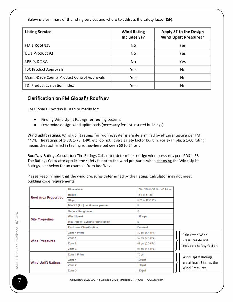
Below is a summary of the listing services and where to address the safety factor (SF).
Listing Service Wind Rating Includes SF?
Apply SF to the Design Wind Uplift Pressures?
FM’s RoofNav No Yes
UL’s Product iQ No Yes
SPRI’s DORA No Yes
FBC Product Approvals Yes No
Miami-Dade County Product Control Approvals Yes No
TDI Product Evaluation Index Yes No Clarification on FM Global’s RoofNav FM Global’s RoofNav is used primarily for:
• Finding Wind Uplift Ratings for roofing systems • Determine design wind uplift loads (necessary for FM-insured buildings)
Wind uplift ratings: Wind uplift ratings for roofing systems are determined by physical testing per FM 4474. The ratings of 1-60, 1-75, 1-90, etc. do not have a safety factor built in. For example, a 1-60 rating means the roof failed in testing somewhere between 60 to 74 psf. RoofNav Ratings Calculator: The Ratings Calculator determines design wind pressures per LPDS 1-28. The Ratings Calculator applies the safety factor to the wind pressures when choosing the Wind Uplift Ratings, see below for an example from RoofNav. Please keep in mind that the wind pressures determined by the Ratings Calculator may not meet building code requirements.
Calculated Wind Pressures do not include a safety factor.
Wind Uplift Ratings are at least 2 times the Wind Pressures.
Copyright© 2020 GAF ▪ 1 Campus Drive Parsippany, NJ 07054 ▪ www.gaf.com
8
ASCE
7-1
6 Gu
ide
Publ
ished
10/
2020
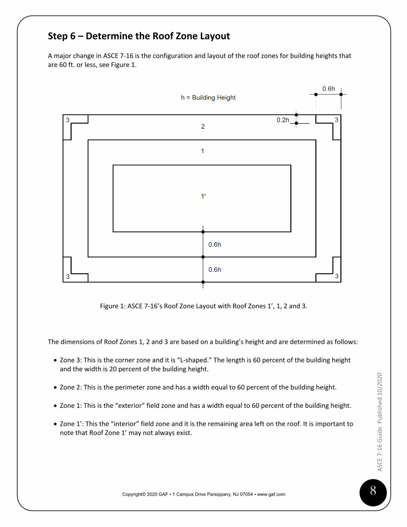
Step 6 – Determine the Roof Zone Layout A major change in ASCE 7-16 is the configuration and layout of the roof zones for building heights that are 60 ft. or less, see Figure 1.
Figure 1: ASCE 7-16’s Roof Zone Layout with Roof Zones 1’, 1, 2 and 3. The dimensions of Roof Zones 1, 2 and 3 are based on a building’s height and are determined as follows: • Zone 3: This is the corner zone and it is “L-shaped.” The length is 60 percent of the building height
and the width is 20 percent of the building height.
• Zone 2: This is the perimeter zone and has a width equal to 60 percent of the building height.
• Zone 1: This is the “exterior” field zone and has a width equal to 60 percent of the building height.
• Zone 1’: This the “interior” field zone and it is the remaining area left on the roof. It is important to note that Roof Zone 1’ may not always exist.
Copyright© 2020 GAF ▪ 1 Campus Drive Parsippany, NJ 07054 ▪ www.gaf.com
9
ASCE
7-1
6 Gu
ide
Pub
lishe
d 10
/ 202
0
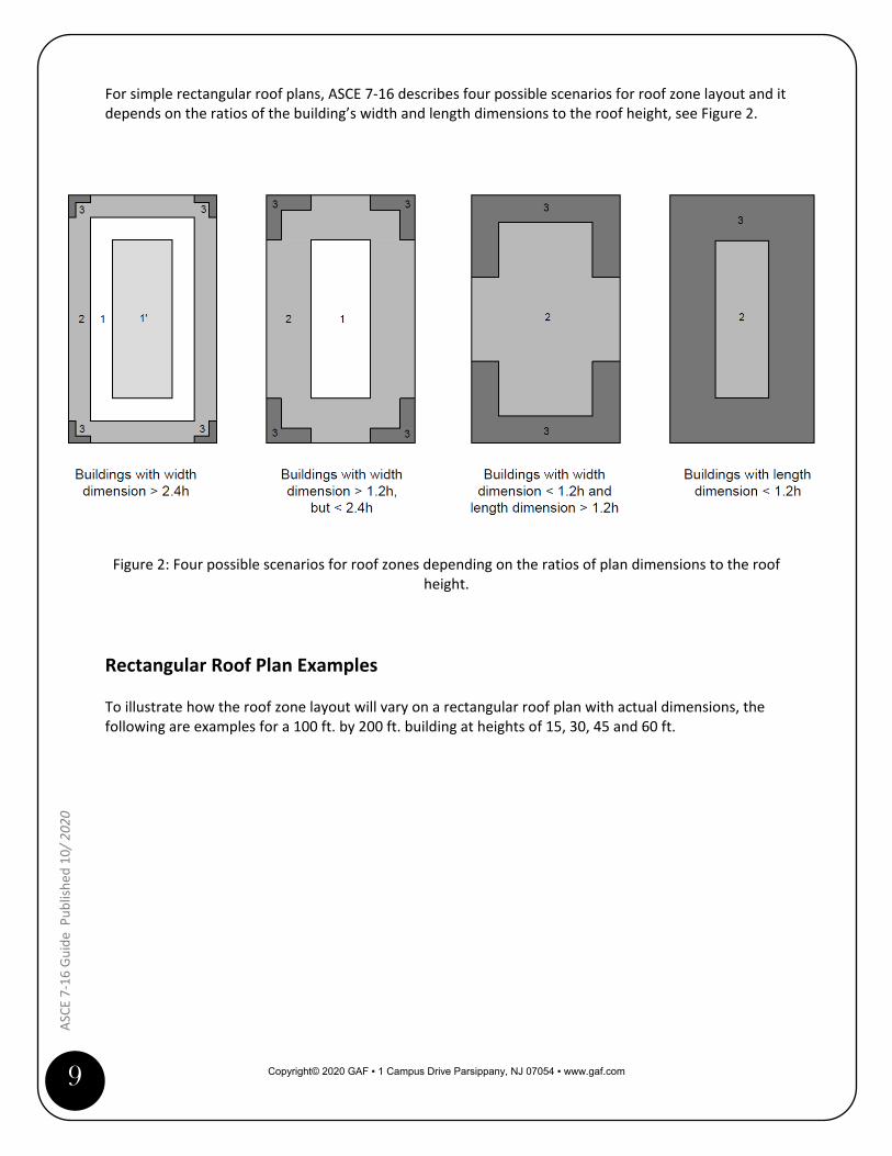
For simple rectangular roof plans, ASCE 7-16 describes four possible scenarios for roof zone layout and it depends on the ratios of the building’s width and length dimensions to the roof height, see Figure 2.
Figure 2: Four possible scenarios for roof zones depending on the ratios of plan dimensions to the roof
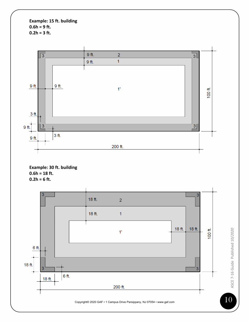
height. Rectangular Roof Plan Examples To illustrate how the roof zone layout will vary on a rectangular roof plan with actual dimensions, the following are examples for a 100 ft. by 200 ft. building at heights of 15, 30, 45 and 60 ft.
Copyright© 2020 GAF ▪ 1 Campus Drive Parsippany, NJ 07054 ▪ www.gaf.com
10
ASCE
7-1
6 Gu
ide
Publ
ished
10/
2020
Example: 15 ft. building 0.6h = 9 ft. 0.2h = 3 ft. Example: 30 ft. building 0.6h = 18 ft. 0.2h = 6 ft.

Copyright© 2020 GAF ▪ 1 Campus Drive Parsippany, NJ 07054 ▪ www.gaf.com
11
ASCE
7-1
6 Gu
ide
Pub
lishe
d 10
/ 202
0
Example: 45 ft. building 0.6h = 27 ft. 0.2h = 9 ft. Example: 60 ft. building 0.6h = 36 ft. 0.2h = 12 ft.
Copyright© 2020 GAF ▪ 1 Campus Drive Parsippany, NJ 07054 ▪ www.gaf.com
12
ASCE
7-1
6 Gu
ide
Publ
ished
10/
2020
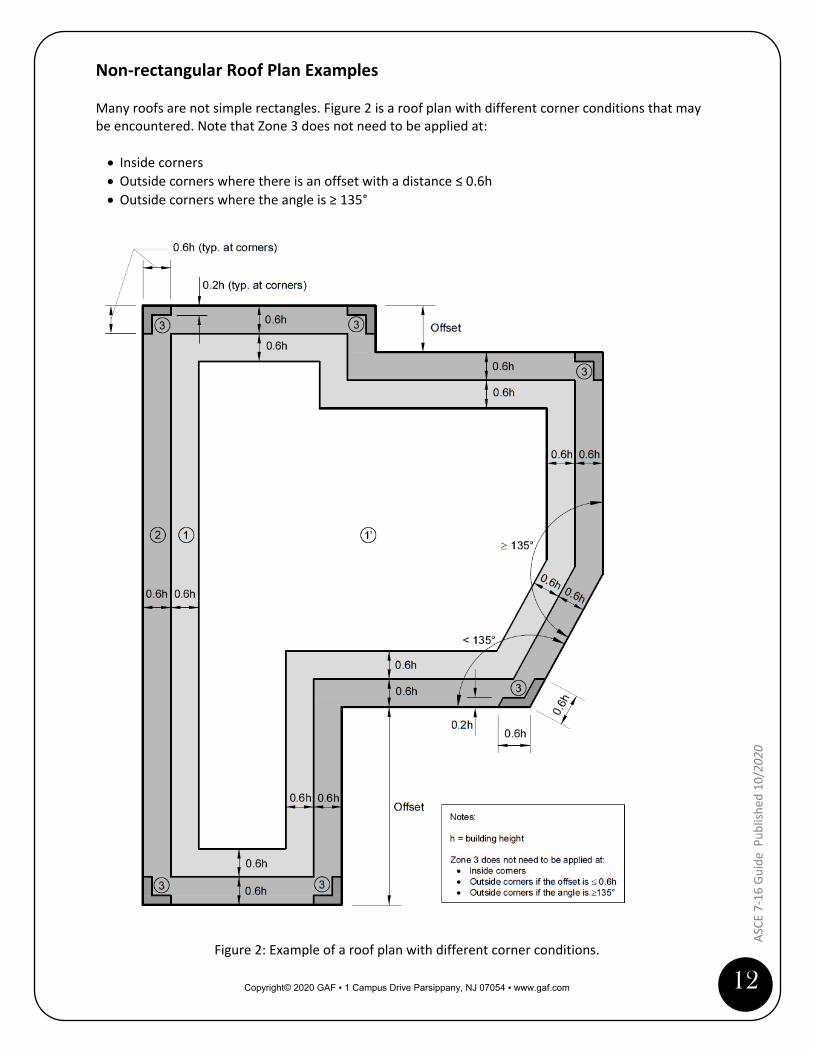
Non-rectangular Roof Plan Examples Many roofs are not simple rectangles. Figure 2 is a roof plan with different corner conditions that may be encountered. Note that Zone 3 does not need to be applied at: • Inside corners • Outside corners where there is an offset with a distance ≤ 0.6h • Outside corners where the angle is ≥ 135°
Figure 2: Example of a roof plan with different corner conditions.
Copyright© 2020 GAF ▪ 1 Campus Drive Parsippany, NJ 07054 ▪ www.gaf.com
13
ASCE
7-1
6 Gu
ide
Pub
lishe
d 10
/ 202
0
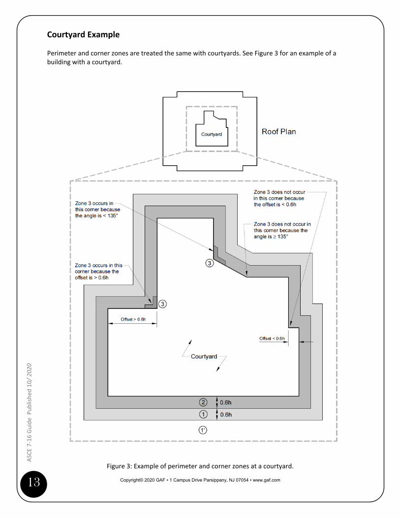
Courtyard Example Perimeter and corner zones are treated the same with courtyards. See Figure 3 for an example of a building with a courtyard.
Figure 3: Example of perimeter and corner zones at a courtyard.

Copyright© 2020 GAF ▪ 1 Campus Drive Parsippany, NJ 07054 ▪ www.gaf.com
14
ASCE
7-1
6 Gu
ide
Publ
ished
10/
2020
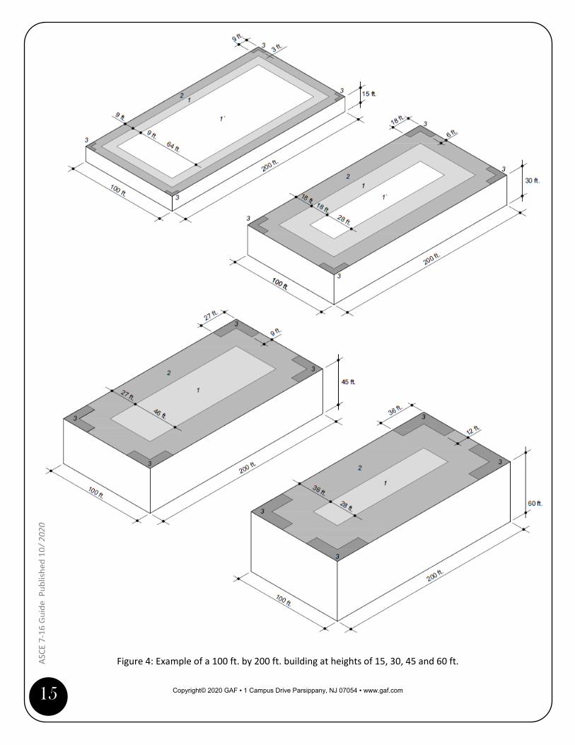
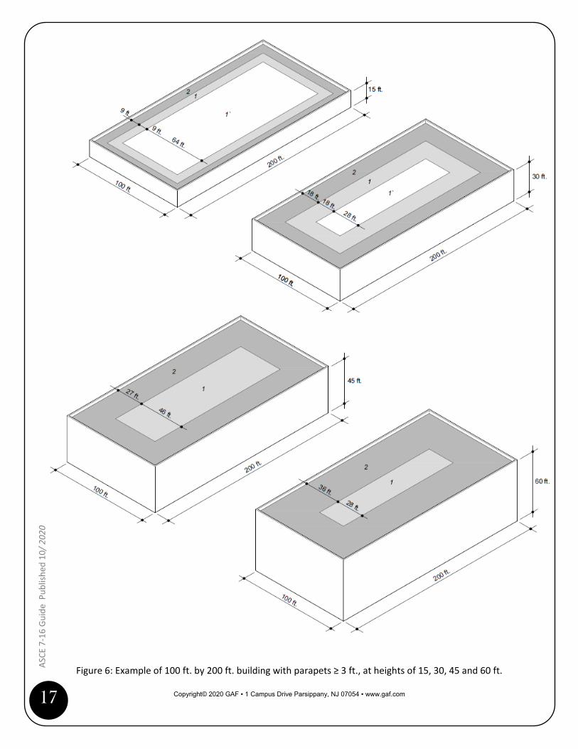
Roof Zone 1’ (interior field) Roof Zone 1’ is not going to exist on every roof. For example, Figure 4 illustrates how Zone 1’ will change—and eventually go away—by altering the height of a 100 ft. by 200 ft. building. Likewise, Figure 5 illustrates how changing the building’s width while keeping the height the same, also affects Zone 1’. If Zone 1’ is relatively small, a practical approach is to use the same roofing system attachment as Zone 1 (exterior field). This is acceptable and would be conservative, while simplifying the layout. Parapets ≥ 3 feet If a building has a parapet or wall that is 3 ft. or higher and it is provided around the perimeter of a roof zone, Zone 3 (corners) can be treated as Zone 2 (perimeter). See Figure 6 for examples of 100 ft. by 200 ft. building at heights of 15, 30, 45 and 60 ft. Lookup Tables with 0.6h and 0.2h Calculations The tables below can be used as an easy reference to determine the 0.6h and 0.2h dimensions for buildings with heights from 15 to 60 ft.
Bldg. height, h
(feet)
0.6h
(feet)
0.2h
(feet)
15 9 316 9.6 3.217 10.2 3.418 10.8 3.619 11.4 3.820 12 421 12.6 4.222 13.2 4.423 13.8 4.624 14.4 4.825 15 526 15.6 5.227 16.2 5.428 16.8 5.629 17.4 5.830 18 631 18.6 6.232 19.2 6.433 19.8 6.634 20.4 6.835 21 736 21.6 7.237 22.2 7.4
Bldg. height, h
(feet)
0.6h
(feet)
0.2h
(feet)
38 22.8 7.639 23.4 7.840 24 841 24.6 8.242 25.2 8.443 25.8 8.644 26.4 8.845 27 946 27.6 9.247 28.2 9.448 28.8 9.649 29.4 9.850 30 1051 30.6 10.252 31.2 10.453 31.8 10.654 32.4 10.855 33 1156 33.6 11.257 34.2 11.458 34.8 11.659 35.4 11.860 36 12
Copyright© 2020 GAF ▪ 1 Campus Drive Parsippany, NJ 07054 ▪ www.gaf.com
15
ASCE
7-1
6 Gu
ide
Pub
lishe
d 10
/ 202
0
Figure 4: Example of a 100 ft. by 200 ft. building at heights of 15, 30, 45 and 60 ft.

Copyright© 2020 GAF ▪ 1 Campus Drive Parsippany, NJ 07054 ▪ www.gaf.com
16
ASCE
7-1
6 Gu
ide
Publ
ished
10/
2020
Figure 5: Example of a 30 ft. high building with widths of 100, 60 and 30 ft.
Copyright© 2020 GAF ▪ 1 Campus Drive Parsippany, NJ 07054 ▪ www.gaf.com
17
ASCE
7-1
6 Gu
ide
Pub
lishe
d 10
/ 202
0
Figure 6: Example of 100 ft. by 200 ft. building with parapets ≥ 3 ft., at heights of 15, 30, 45 and 60 ft.

Copyright© 2020 GAF ▪ 1 Campus Drive Parsippany, NJ 07054 ▪ www.gaf.com
18
ASCE
7-1
6 Gu
ide
Publ
ished
10/
2020
Application Considerations for Roof Zones 2 and 3 ASCE 7-16 is significantly impacting how roof design has been traditionally done. You will notice that there will be an increase in the amount of fasteners for mechanically attached roofing systems because: • Design wind uplift pressures have increased for all roof zones. • The size of perimeter zones are larger than with ASCE 7-05 and ASCE 7-10.
There are two ways to address perimeter (Zone 2) and corner (Zone 3) zones: • Performance-based • Prescriptive enhancement
Performance-based This approach is where you select a roofing system with a wind uplift rating that is applicable for Zones 1’, 1, 2 and 3. This is the most reliable method to ensure building code compliance. This approach includes: • Using a combination of multiple wind ratings that are applicable for the respective roof zone, or • Using a roof system throughout the entire roof area that has a wind rating adequate for Zone 3 (or
Zone 2 if there is a parapet ≥ 3 ft.).
Prescriptive enhancement This approach originates from FM Global Property Loss Prevention Data Sheet 1-29, “Roof Deck Securement and Above-Deck Roof Components” (FM 1-29) and is a widely accepted practice. See Appendix B for additional information on FM 1-29. The Zone 2 and 3 enhancements should be extrapolations based on Zone 1 and not Zone 1’. Important note: It should be verified if the prescriptive enhancement method is acceptable with the authority-having-jurisdiction (AHJ). This guide offers assistance with conventional mechanically attached roofing systems and Drill-TecTM RhinoBond roofing systems.

Copyright© 2020 GAF ▪ 1 Campus Drive Parsippany, NJ 07054 ▪ www.gaf.com
19
ASCE
7-1
6 Gu
ide
Pub
lishe
d 10
/ 202
0
Conventional Mechanically Attached Roofing Systems The following are suggested installation methods to approach perimeter and corner zones with conventional mechanically attached roofing systems for buildings less than 60 ft. in height: • Method A – Standard Picture Framing • Method B – Modified Picture Framing • Method C – Full Size and Half Size Sheets with Intermediate Fastener Rows • Method D – Full Size Sheets with Intermediate Fastener Rows
Important Note! FM 1-29 was updated in February 2020. The Data Sheet revised the parameters for fastener row spacing used in the perimeter and corner zones. The installation methods shown in the previous edition of this guide followed the earlier version of FM 1-29. The changes to FM 1-29 are as follows: • Perimeters (Zone 2): the distance between fastener rows is no more than 67% of the row spacing
needed for the wind uplift resistance rating for Zone 1, or one row of intermediate fasteners. • Corners (Zone 3): the distance between fastener rows is no more than 50% of the row spacing
needed for the wind uplift resistance rating for Zone 1, or one row of intermediate fasteners. Therefore, the row spacing in the corner zones can be the same as in the perimeter zones for conventional mechanically attached roof systems. The roof layouts in this guide reflect this change to FM 1-29.
Copyright© 2020 GAF ▪ 1 Campus Drive Parsippany, NJ 07054 ▪ www.gaf.com
20
ASCE
7-1
6 Gu
ide
Publ
ished
10/
2020
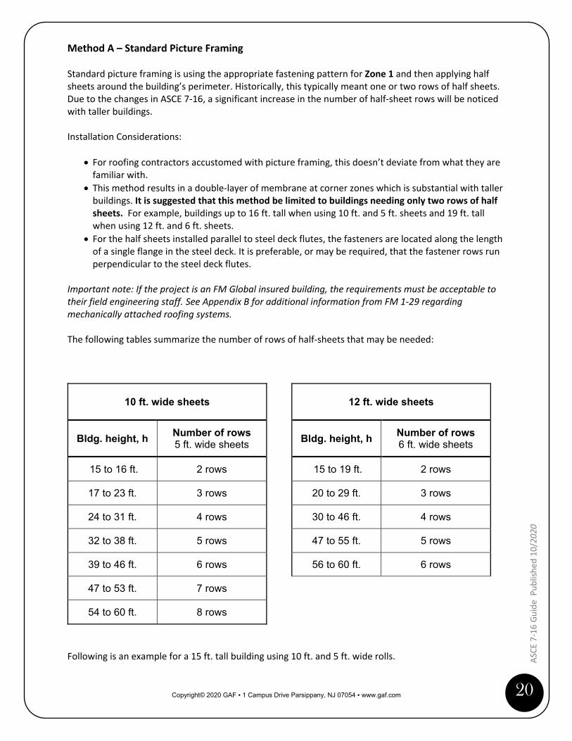
Method A – Standard Picture Framing Standard picture framing is using the appropriate fastening pattern for Zone 1 and then applying half sheets around the building’s perimeter. Historically, this typically meant one or two rows of half sheets. Due to the changes in ASCE 7-16, a significant increase in the number of half-sheet rows will be noticed with taller buildings. Installation Considerations:
• For roofing contractors accustomed with picture framing, this doesn’t deviate from what they are familiar with.
• This method results in a double-layer of membrane at corner zones which is substantial with taller buildings. It is suggested that this method be limited to buildings needing only two rows of half sheets. For example, buildings up to 16 ft. tall when using 10 ft. and 5 ft. sheets and 19 ft. tall when using 12 ft. and 6 ft. sheets.
• For the half sheets installed parallel to steel deck flutes, the fasteners are located along the length of a single flange in the steel deck. It is preferable, or may be required, that the fastener rows run perpendicular to the steel deck flutes.
Important note: If the project is an FM Global insured building, the requirements must be acceptable to their field engineering staff. See Appendix B for additional information from FM 1-29 regarding mechanically attached roofing systems.
The following tables summarize the number of rows of half-sheets that may be needed:
10 ft. wide sheets
Bldg. height, h Number of rows 5 ft. wide sheets
15 to 16 ft. 2 rows
17 to 23 ft. 3 rows
24 to 31 ft. 4 rows
32 to 38 ft. 5 rows
39 to 46 ft. 6 rows
47 to 53 ft. 7 rows
54 to 60 ft. 8 rows
12 ft. wide sheets
Bldg. height, h Number of rows 6 ft. wide sheets
15 to 19 ft. 2 rows
20 to 29 ft. 3 rows
30 to 46 ft. 4 rows
47 to 55 ft. 5 rows
56 to 60 ft. 6 rows
Following is an example for a 15 ft. tall building using 10 ft. and 5 ft. wide rolls.

Copyright© 2020 GAF ▪ 1 Campus Drive Parsippany, NJ 07054 ▪ www.gaf.com
21
ASCE
7-1
6 Gu
ide
Pub
lishe
d 10
/ 202
0
Method A – Standard Picture Framing Example: 15 ft. building 0.6h = 9 ft. 10 ft. and 5 ft. sheets
Copyright© 2020 GAF ▪ 1 Campus Drive Parsippany, NJ 07054 ▪ www.gaf.com
22
ASCE
7-1
6 Gu
ide
Publ
ished
10/
2020
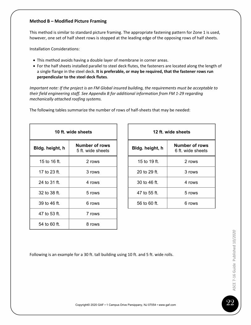
Method B – Modified Picture Framing This method is similar to standard picture framing. The appropriate fastening pattern for Zone 1 is used, however, one set of half sheet rows is stopped at the leading edge of the opposing rows of half sheets. Installation Considerations: • This method avoids having a double layer of membrane in corner areas. • For the half sheets installed parallel to steel deck flutes, the fasteners are located along the length of
a single flange in the steel deck. It is preferable, or may be required, that the fastener rows run perpendicular to the steel deck flutes.
Important note: If the project is an FM Global insured building, the requirements must be acceptable to their field engineering staff. See Appendix B for additional information from FM 1-29 regarding mechanically attached roofing systems. The following tables summarize the number of rows of half-sheets that may be needed:
10 ft. wide sheets
Bldg. height, h Number of rows 5 ft. wide sheets
15 to 16 ft. 2 rows
17 to 23 ft. 3 rows
24 to 31 ft. 4 rows
32 to 38 ft. 5 rows
39 to 46 ft. 6 rows
47 to 53 ft. 7 rows
54 to 60 ft. 8 rows
12 ft. wide sheets
Bldg. height, h Number of rows 6 ft. wide sheets
15 to 19 ft. 2 rows
20 to 29 ft. 3 rows
30 to 46 ft. 4 rows
47 to 55 ft. 5 rows
56 to 60 ft. 6 rows
Following is an example for a 30 ft. tall building using 10 ft. and 5 ft. wide rolls.

Copyright© 2020 GAF ▪ 1 Campus Drive Parsippany, NJ 07054 ▪ www.gaf.com
23
ASCE
7-1
6 Gu
ide
Pub
lishe
d 10
/ 202
0
Method B – Modified Picture Framing Example: 30 ft. building 0.6h = 18 ft. 10 ft. and 5 ft. sheets

Copyright© 2020 GAF ▪ 1 Campus Drive Parsippany, NJ 07054 ▪ www.gaf.com
24
ASCE
7-1
6 Gu
ide
Publ
ished
10/
2020
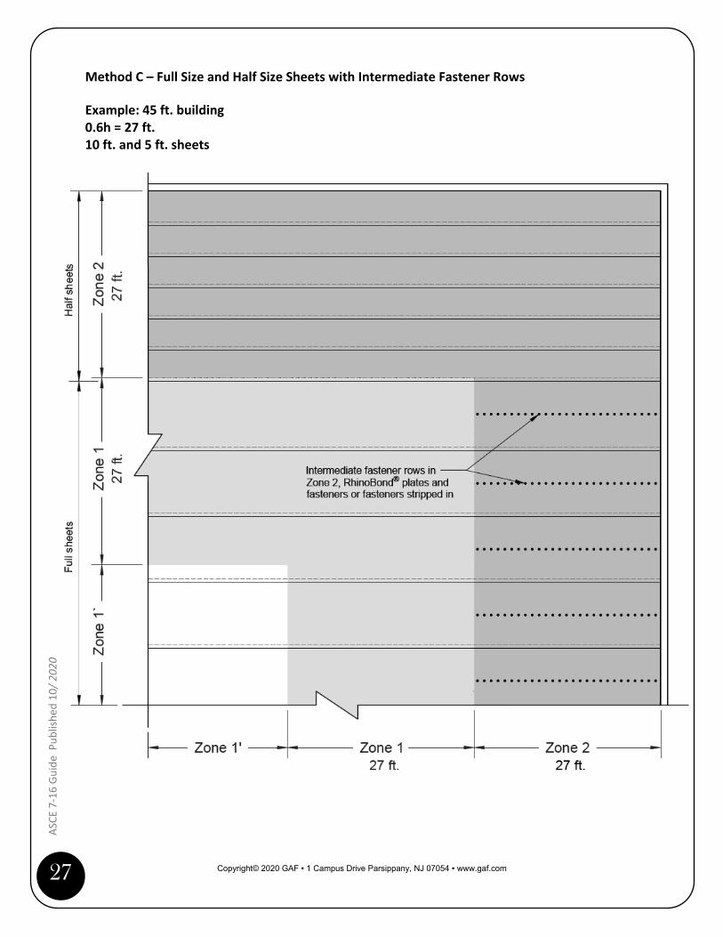
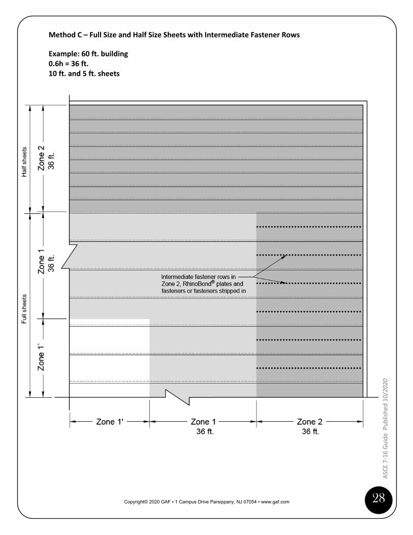
Method C – Full Size and Half Size Sheets with Intermediate Fastener Rows This method is similar to Method B, where the appropriate fastening pattern for Zone 1 is used; except the half sheets are just installed where they are perpendicular to steel deck flutes. In the perimeter zones (Zone 2) without half sheets, intermediate rows of fasteners are used. The intermediate rows may be fasteners that are stripped in (a.k.a., fingers), or Drill-TecTM RhinoBond plates and fasteners. Installation Considerations: • This method avoids having a double layer of membrane in corner areas. • This eliminates the placement of fasteners along the length of a single flange in the steel deck.
Important note: If the project is an FM Global insured building, the requirements must be acceptable to their field engineering staff. See Appendix B for additional information from FM 1-29 regarding mechanically attached roofing systems. The following tables summarize the number of rows of half-sheets that may be needed:
10 ft. wide sheets
Bldg. height, h Number of rows 5 ft. wide sheets
15 to 16 ft. 2 rows
17 to 23 ft. 3 rows
24 to 31 ft. 4 rows
32 to 38 ft. 5 rows
39 to 46 ft. 6 rows
47 to 53 ft. 7 rows
54 to 60 ft. 8 rows
12 ft. wide sheets
Bldg. height, h Number of rows 6 ft. wide sheets
15 to 19 ft. 2 rows
20 to 29 ft. 3 rows
30 to 46 ft. 4 rows
47 to 55 ft. 5 rows
56 to 60 ft. 6 rows
Following are examples using 10 ft. and 5 ft. sheets for 15, 30, 45 and 60 ft. tall buildings.

Copyright© 2020 GAF ▪ 1 Campus Drive Parsippany, NJ 07054 ▪ www.gaf.com
25
ASCE
7-1
6 Gu
ide
Pub
lishe
d 10
/ 202
0
Method C – Full Size and Half Size Sheets with Intermediate Fastener Rows Example: 15 ft. building 0.6h = 9 ft. 10 ft. and 5 ft. sheets

Copyright© 2020 GAF ▪ 1 Campus Drive Parsippany, NJ 07054 ▪ www.gaf.com
26
ASCE
7-1
6 Gu
ide
Publ
ished
10/
2020
Method C – Full Size and Half Size Sheets with Intermediate Fastener Rows Example: 30 ft. building 0.6h = 18 ft. 10 ft. and 5 ft. sheets
Copyright© 2020 GAF ▪ 1 Campus Drive Parsippany, NJ 07054 ▪ www.gaf.com
27
ASCE
7-1
6 Gu
ide
Pub
lishe
d 10
/ 202
0
Method C – Full Size and Half Size Sheets with Intermediate Fastener Rows Example: 45 ft. building 0.6h = 27 ft. 10 ft. and 5 ft. sheets
Copyright© 2020 GAF ▪ 1 Campus Drive Parsippany, NJ 07054 ▪ www.gaf.com
28
ASCE
7-1
6 Gu
ide
Publ
ished
10/
2020
Method C – Full Size and Half Size Sheets with Intermediate Fastener Rows Example: 60 ft. building 0.6h = 36 ft. 10 ft. and 5 ft. sheets

Copyright© 2020 GAF ▪ 1 Campus Drive Parsippany, NJ 07054 ▪ www.gaf.com
29
ASCE
7-1
6 Gu
ide
Pub
lishe
d 10
/ 202
0
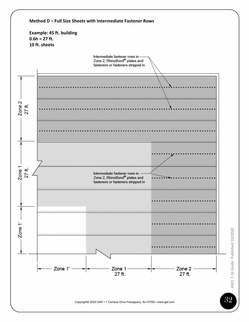
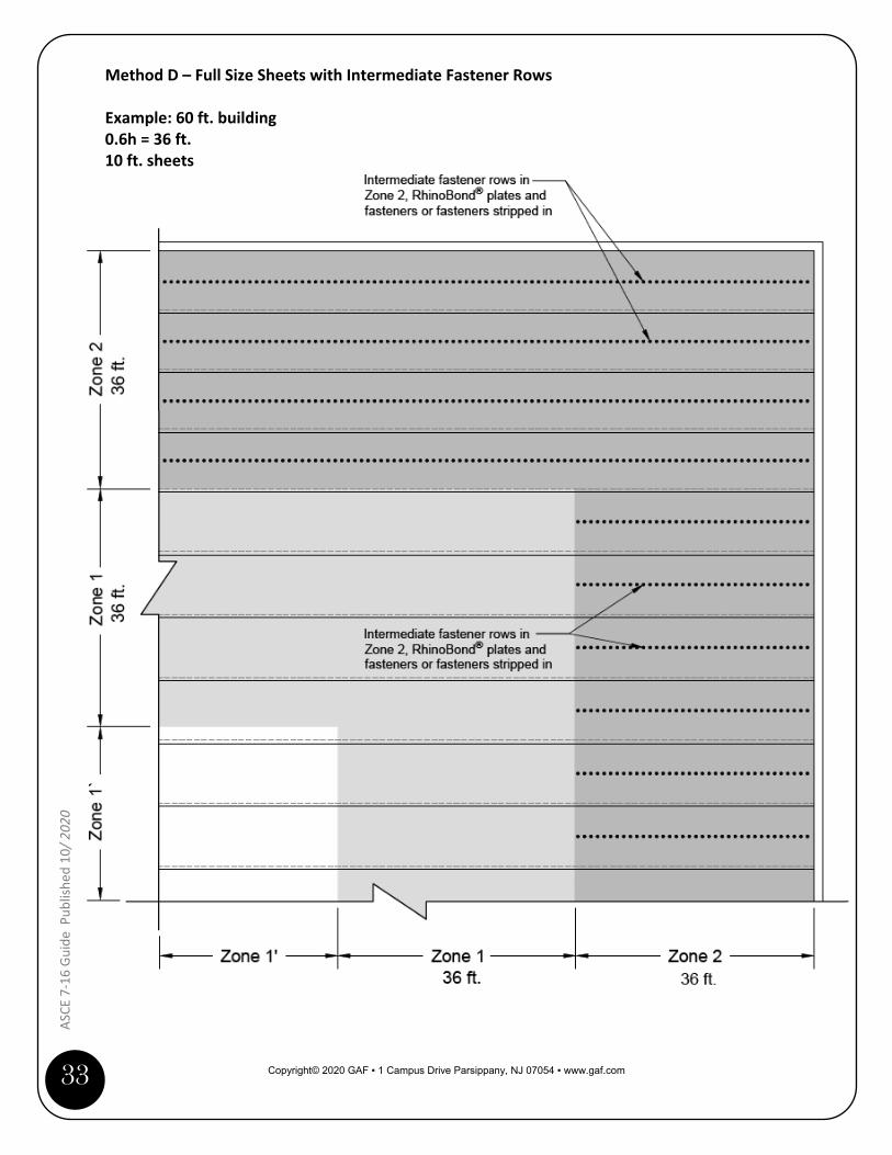
Method D – Full Size Sheets with Intermediate Fastener Rows This method uses full size membrane sheets for the entire roof area. The appropriate fastening pattern for Zone 1 is used and intermediate rows of fasteners are used in perimeter zones (Zone 2). The intermediate rows may be fasteners that are stripped in (a.k.a., fingers), or Drill-TecTM RhinoBond plates and fasteners. Installation Considerations:
• This method avoids using half sheets. • This eliminates the placement of fasteners along the length of a single flange in the steel deck.
Important note: If the project is an FM Global insured building, the requirements must be acceptable to their field engineering staff. See Appendix B for additional information from FM 1-29 regarding mechanically attached roofing systems. Following are examples using 10 ft. sheets for 15, 30, 45 and 60 ft. tall buildings.

Copyright© 2020 GAF ▪ 1 Campus Drive Parsippany, NJ 07054 ▪ www.gaf.com
30
ASCE
7-1
6 Gu
ide
Publ
ished
10/
2020
Method D – Full Size Sheets with Intermediate Fastener Rows Example: 15 ft. building 0.6h = 9 ft. 10 ft. sheets

Copyright© 2020 GAF ▪ 1 Campus Drive Parsippany, NJ 07054 ▪ www.gaf.com
31
ASCE
7-1
6 Gu
ide
Pub
lishe
d 10
/ 202
0
Method D – Full Size Sheets with Intermediate Fastener Rows Example: 30 ft. building 0.6h = 18 ft. 10 ft. sheets
Copyright© 2020 GAF ▪ 1 Campus Drive Parsippany, NJ 07054 ▪ www.gaf.com
32
ASCE
7-1
6 Gu
ide
Publ
ished
10/
2020
Method D – Full Size Sheets with Intermediate Fastener Rows Example: 45 ft. building 0.6h = 27 ft. 10 ft. sheets
Copyright© 2020 GAF ▪ 1 Campus Drive Parsippany, NJ 07054 ▪ www.gaf.com
33
ASCE
7-1
6 Gu
ide
Pub
lishe
d 10
/ 202
0
Method D – Full Size Sheets with Intermediate Fastener Rows Example: 60 ft. building 0.6h = 36 ft. 10 ft. sheets

Copyright© 2020 GAF ▪ 1 Campus Drive Parsippany, NJ 07054 ▪ www.gaf.com
34
ASCE
7-1
6 Gu
ide
Publ
ished
10/
2020
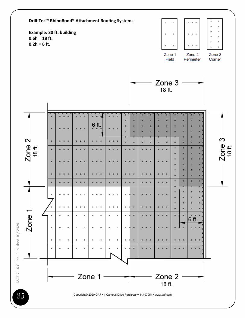
Drill-Tec™ RhinoBond® Attachment Roofing Systems Follow the fastening patterns found in the Drill-Tec™ RhinoBond® Attachment System Overview & General Requirements Manual. Make sure to use Zone 1—not Zone 1’—as the basis for the field zone. Installation Considerations: • With this method, the L-shaped corner zones (Zone 3) should be followed. This is because the
fastening pattern is based on fasteners per board and not fastener row spacing. • If a portion of an insulation board extends into another zone, it must use the higher fastening
pattern. Following is an example for a 30 ft. tall building.
Copyright© 2020 GAF ▪ 1 Campus Drive Parsippany, NJ 07054 ▪ www.gaf.com
35
ASCE
7-1
6 Gu
ide
Pub
lishe
d 10
/ 202
0
Drill-Tec™ RhinoBond® Attachment Roofing Systems Example: 30 ft. building 0.6h = 18 ft. 0.2h = 6 ft.

Copyright© 2020 GAF ▪ 1 Campus Drive Parsippany, NJ 07054 ▪ www.gaf.com
36
ASCE
7-1
6 Gu
ide
Publ
ished
10/
2020
Appendix A: ASCE 7 Comparison There are some noteworthy differences between the three ASCE 7 editions and they include: the wind speed maps, roof zones, enclosure classifications, external pressure coefficients, and the equation to calculate velocity pressures. Wind speed maps ASCE 7-05 ASCE 7-10 ASCE 7-16
Maps
One map for contiguous US and Alaska
Three maps for contiguous US and Alaska: • Category I buildings • Category II buildings • Category III and IV buildings
Four maps for contiguous US and Alaska: • Category I buildings • Category II buildings • Category III buildings • Category IV buildings
Additional wind speed maps for Hawaii.
Design Method
Wind speeds based on determining ASD pressures.
Wind speeds based on determining Ultimate (Strength) Design pressures.
Wind speeds based on determining Ultimate (Strength) Design pressures.
Roof zones ASCE 7-05 and ASCE 7-10 have three roof zones: field, perimeter and corner. ASCE 7-16 added another zone and it presents the potential to have four roof zones: interior, field, perimeter and corner. The calculations to determine the zone dimensions also changed, see table below:
ASCE Edition Zones Zone Dimensions
ASCE 7-05 and ASCE 7-10
Zone 1 (field) Zone 2 (perimeter) Zone 3 (corner)
Zones 2 and 3: The smaller of 10% of least horizontal dimension or 0.4h; but not less than 4% of least horizontal dimension; or 3 feet.
ASCE 7-16 Zone 1’ (interior) Zone 1 (field) Zone 2 (perimeter) Zone 3 (corner)
Zones 1 and 2: Width is 60% of building height. Zone 3: “L-shaped” with the width being 20% of building height and length is 60% of building height.

Copyright© 2020 GAF ▪ 1 Campus Drive Parsippany, NJ 07054 ▪ www.gaf.com
37
ASCE
7-1
6 Gu
ide
Pub
lishe
d 10
/ 202
0
Variables used to Determine Wind Uplift Pressures The formula to determine design wind uplift pressures (p) is: p = qh [(GCp) − (GCpi)] where: qh = velocity pressure GCp = external pressure coefficient GCpi = internal pressure coefficient Comparing ASCE 7-05, ASCE 7-10 and ASCE 7-16, there are differences to the three variables and they are explained below. Velocity pressure (qh): This is determined by an equation which has changed slightly with each edition of ASCE 7. ASCE 7-05 Velocity Pressure Equation
qh = 0.00256 (Kz)(Kzt) (Kd) (V2)(I)
Where: qh = velocity pressure at mean roof height Kz = exposure coefficient based on exposure and height Kzt = topography factor Kd = wind directionality factor V = basic wind speed for the location I = Importance Factor (based on Occupancy Category)
ASCE 7-10 Velocity Pressure Equation
qh = 0.00256 (Kz)(Kzt) (Kd) (V2) The Importance Factor (I) was removed from the equation because the three wind maps in ASCE 7-10 take into account the Risk Category. Therefore, what was considered the “Importance Factor” is addressed by the wind speeds in each map. ASCE 7-16 Velocity Pressure Equation
qh = 0.00256 (Kz)(Kzt) (Kd) (Ke) (V2) A ground elevation factor (Ke) was added to adjust for air density at higher elevations. It is permitted by ASCE 7-16 to be 1.0 for all locations. Using 1.0 is most conservative.
Copyright© 2020 GAF ▪ 1 Campus Drive Parsippany, NJ 07054 ▪ www.gaf.com
38
ASCE
7-1
6 Gu
ide
Publ
ished
10/
2020
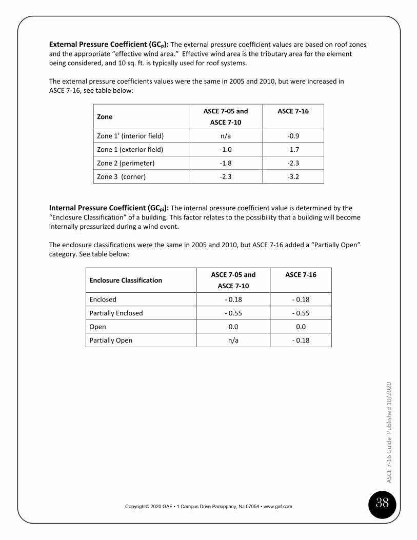
External Pressure Coefficient (GCp): The external pressure coefficient values are based on roof zones and the appropriate “effective wind area.” Effective wind area is the tributary area for the element being considered, and 10 sq. ft. is typically used for roof systems. The external pressure coefficients values were the same in 2005 and 2010, but were increased in ASCE 7-16, see table below:
Zone ASCE 7-05 and
ASCE 7-10 ASCE 7-16
Zone 1’ (interior field) n/a -0.9
Zone 1 (exterior field) -1.0 -1.7
Zone 2 (perimeter) -1.8 -2.3
Zone 3 (corner) -2.3 -3.2 Internal Pressure Coefficient (GCpi): The internal pressure coefficient value is determined by the “Enclosure Classification” of a building. This factor relates to the possibility that a building will become internally pressurized during a wind event. The enclosure classifications were the same in 2005 and 2010, but ASCE 7-16 added a “Partially Open” category. See table below:
Enclosure Classification ASCE 7-05 and
ASCE 7-10 ASCE 7-16
Enclosed - 0.18 - 0.18
Partially Enclosed - 0.55 - 0.55
Open 0.0 0.0
Partially Open n/a - 0.18

Copyright© 2020 GAF ▪ 1 Campus Drive Parsippany, NJ 07054 ▪ www.gaf.com
39
ASCE
7-1
6 Gu
ide
Pub
lishe
d 10
/ 202
0
Appendix B: FM 1-29 Prescriptive Enhancements for Perimeters and Corners This appendix contains excerpts from FM Global Property Loss Prevention Data Sheet 1-29, “Roof Deck Securement and Above-Deck Roof Components” (FM 1-29) on their prescriptive enhancements for Zones 2 and 3. The information provided is limited to mechanically attached single-ply roof membranes installed over cementitious panel, wood and steel decks. Please refer to FM 1-29 for additional requirements and information. FM 1-29 has the following parameters for permitting prescriptive enhancement:
• The rows of roof cover fasteners should run perpendicular to the steel deck ribs, and the deck should be designed to resist the design wind pressure applied at the roof cover fastener row spacing.
• The Zone 2 and 3 enhancements should be extrapolations based on Zone 1 and not Zone 1’. Above-deck Roof Components Information The following excerpts are taken from FM 1-29 and are applicable for above-deck roof components over all roof decks except lightweight insulating concrete (LWIC) decks:
“2.2.10 Above-Deck Roof Components (Other Than LWIC)
2.2.10.1 Wind Uplift Resistance
2.2.10.1.1 Provide one of the following options to secure Zones 2 and 3:
A. Use a roof system with an FM Approval wind uplift rating that is acceptable for Zones 1’, 1, 2, and 3 per the Ratings Calculator of RoofNav or DS 1-28. That could entail using a system throughout the entire roof that had a wind rating adequate for Zone 3, or using a system that has a varied fastener spacing and multiple wind ratings that are adequate for the respective roof zone.”

Copyright© 2020 GAF ▪ 1 Campus Drive Parsippany, NJ 07054 ▪ www.gaf.com
40
ASCE
7-1
6 Gu
ide
Publ
ished
10/
2020
Mechanically fastened single-ply (MFSP) membrane covers: The following section from FM 1-29 is specific to conventional mechanically attached and Drill-Tec™ RhinoBond® attached single-ply membranes:
“2.2.10.11 Mechanically Fastened Single-Ply (MFSP) Membrane Covers: Design Recommendations
This section is applicable to both in-seam and point-attached single-ply roof membranes.
2.2.10.11.1 Install a roof system in Zone 2 and Zone 3 using one of the following options:
A. Enhance FM Approved MFSP roof covers in Zone 2 and Zone 3 in a performance-based
manner as follows:
1. Reduce the distance between rows of roof cover fasteners and stress plates or batten bars in Zone 2 and Zone 3 by dividing by the ratio of the required rating for the respective zone to Zone 1. […]
B. Prescriptively enhance FM Approved MFSP roof covers in Zone 2 and Zone 3 by reducing the distance between rows of roof cover fasteners and stress plates or batten bars using one of the following options, as applicable:
1. Zone 2: For single-plies fastened in rows, ensure the distance between rows is no more
than 67% of the FM Approved spacing for the needed wind uplift resistance rating, or one row of intermediate fasteners is provided in between (See Example 2.)
2. Zone 3: For single-plies fastened in rows, the distance between rows is no more than 50% of the FM Approved spacing for the needed wind uplift resistance rating, or one row of intermediate fasteners is provided in between.
NOTE: Intermediate securement for single-plies fastened in rows may be provided by installing intermediate fastener rows over the roof cover and providing a seal strip over it, or by pre-fastening an FM Approved intermediate bonding strip in its center and adhering the underside of the roof cover to the top of both sides of the bonding strip.
3. Zone 2: For point-attached single-plies, decrease the spacing between fastener points in
one or both directions. Ensure total tributary area to each fastener is no more than 67% of the FM Approved spacing. (See Example 3.)
4. Zone 3: For point-attached single-plies, decrease the spacing between fastener points in one or both directions. Ensure total tributary area to each fastener is no more than 50% of the FM Approved spacing. (See Example 3.)
Increased fastening density for single-ply membranes is obtained by using narrower sheets, underside securement methods, or through-fastening covered by seal strips. Fastening increase is not obtained by increasing the number of fasteners along each row, unless substantiated by FM Approval. Increased securement by reducing the distance between rows is recommended as it also reduces deck bending stress and provides better load distribution to the deck securement.”
Copyright© 2020 GAF ▪ 1 Campus Drive Parsippany, NJ 07054 ▪ www.gaf.com
41
ASCE
7-1
6 Gu
ide
Pub
lishe
d 10
/ 202
0
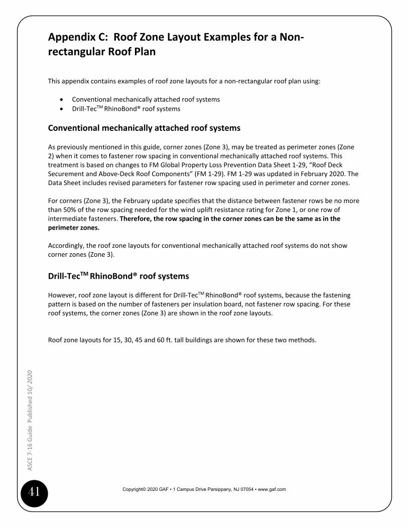
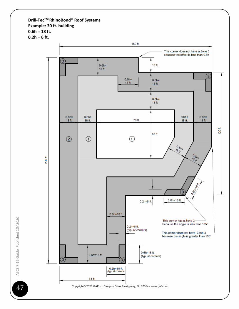
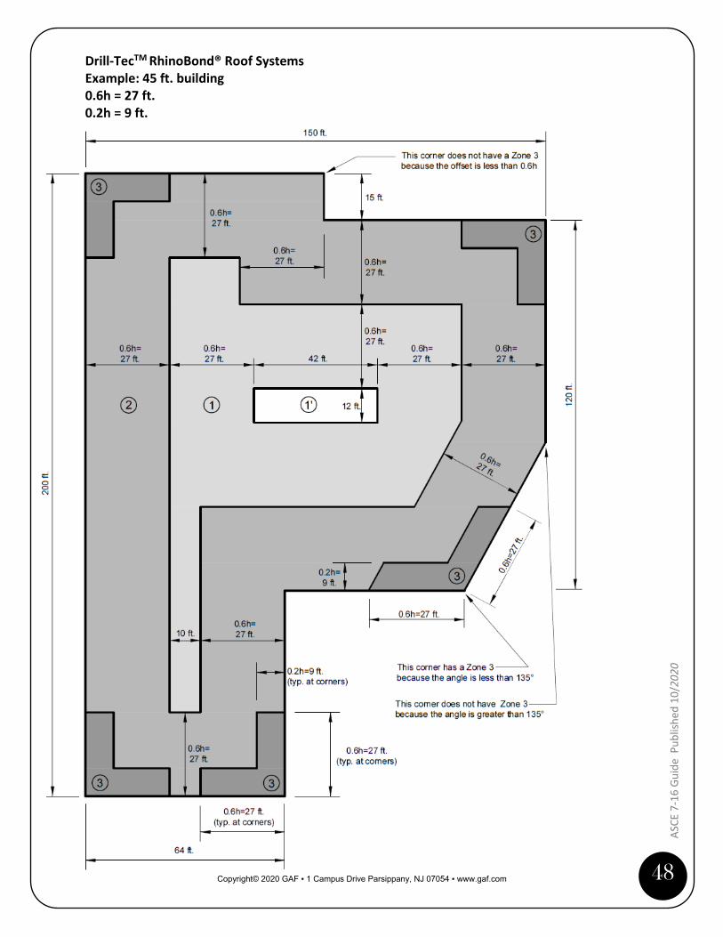
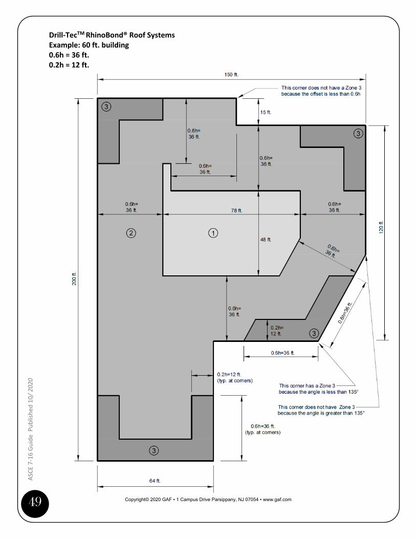
Appendix C: Roof Zone Layout Examples for a Non-rectangular Roof Plan
This appendix contains examples of roof zone layouts for a non-rectangular roof plan using:
• Conventional mechanically attached roof systems • Drill-TecTM RhinoBond® roof systems
Conventional mechanically attached roof systems As previously mentioned in this guide, corner zones (Zone 3), may be treated as perimeter zones (Zone 2) when it comes to fastener row spacing in conventional mechanically attached roof systems. This treatment is based on changes to FM Global Property Loss Prevention Data Sheet 1-29, “Roof Deck Securement and Above-Deck Roof Components” (FM 1-29). FM 1-29 was updated in February 2020. The Data Sheet includes revised parameters for fastener row spacing used in perimeter and corner zones. For corners (Zone 3), the February update specifies that the distance between fastener rows be no more than 50% of the row spacing needed for the wind uplift resistance rating for Zone 1, or one row of intermediate fasteners. Therefore, the row spacing in the corner zones can be the same as in the perimeter zones. Accordingly, the roof zone layouts for conventional mechanically attached roof systems do not show corner zones (Zone 3). Drill-TecTM RhinoBond® roof systems However, roof zone layout is different for Drill-TecTM RhinoBond® roof systems, because the fastening pattern is based on the number of fasteners per insulation board, not fastener row spacing. For these roof systems, the corner zones (Zone 3) are shown in the roof zone layouts. Roof zone layouts for 15, 30, 45 and 60 ft. tall buildings are shown for these two methods.
Copyright© 2020 GAF ▪ 1 Campus Drive Parsippany, NJ 07054 ▪ www.gaf.com
42
ASCE
7-1
6 Gu
ide
Publ
ished
10/
2020
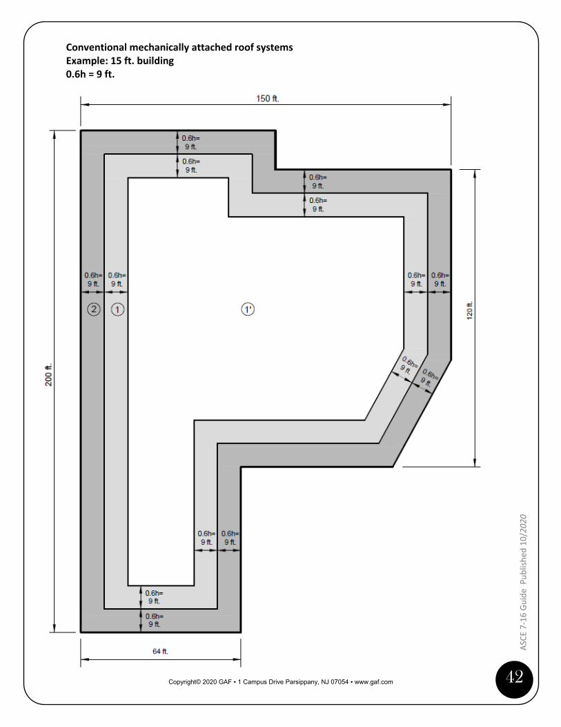
Conventional mechanically attached roof systems Example: 15 ft. building 0.6h = 9 ft.

Copyright© 2020 GAF ▪ 1 Campus Drive Parsippany, NJ 07054 ▪ www.gaf.com
43
ASCE
7-1
6 Gu
ide
Pub
lishe
d 10
/ 202
0
Conventional mechanically attached roof systems Example: 30 ft. building 0.6h = 18 ft.
Copyright© 2020 GAF ▪ 1 Campus Drive Parsippany, NJ 07054 ▪ www.gaf.com
44
ASCE
7-1
6 Gu
ide
Publ
ished
10/
2020
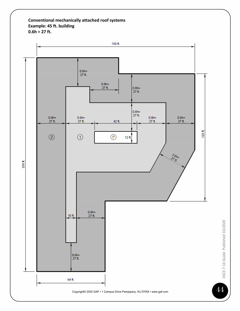
Conventional mechanically attached roof systems Example: 45 ft. building 0.6h = 27 ft.
Copyright© 2020 GAF ▪ 1 Campus Drive Parsippany, NJ 07054 ▪ www.gaf.com
45
ASCE
7-1
6 Gu
ide
Pub
lishe
d 10
/ 202
0
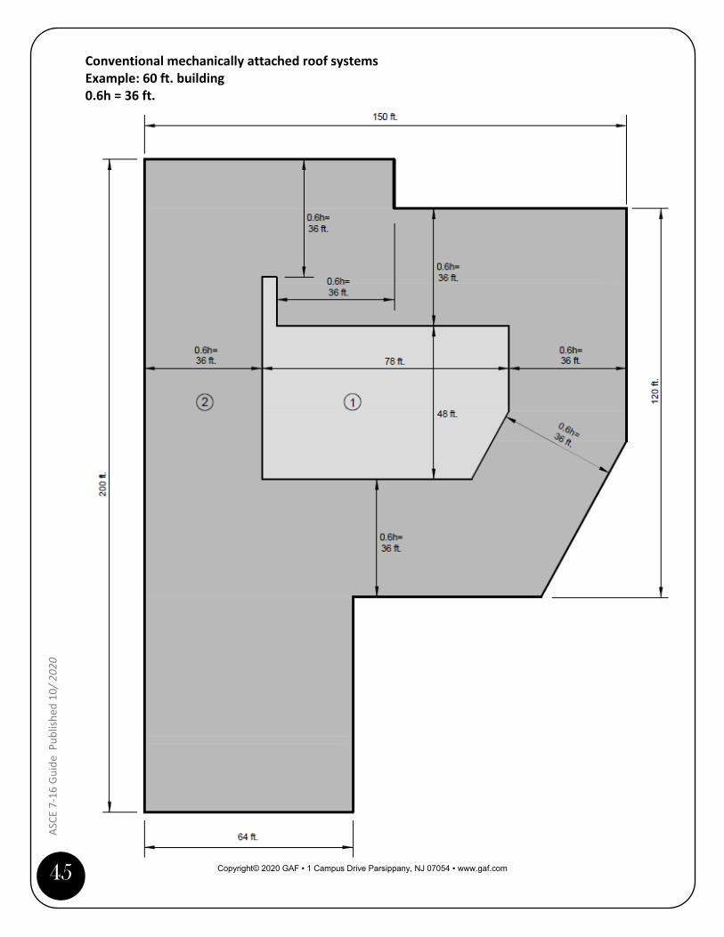
Conventional mechanically attached roof systems Example: 60 ft. building 0.6h = 36 ft.

Copyright© 2020 GAF ▪ 1 Campus Drive Parsippany, NJ 07054 ▪ www.gaf.com
46
ASCE
7-1
6 Gu
ide
Publ
ished
10/
2020
Drill-TecTM RhinoBond® Roof Systems Example: 15 ft. building 0.6h = 9 ft. 0.2h = 3 ft.
Copyright© 2020 GAF ▪ 1 Campus Drive Parsippany, NJ 07054 ▪ www.gaf.com
47
ASCE
7-1
6 Gu
ide
Pub
lishe
d 10
/ 202
0
Drill-TecTM RhinoBond® Roof Systems Example: 30 ft. building 0.6h = 18 ft. 0.2h = 6 ft.
Copyright© 2020 GAF ▪ 1 Campus Drive Parsippany, NJ 07054 ▪ www.gaf.com
48
ASCE
7-1
6 Gu
ide
Publ
ished
10/
2020
Drill-TecTM RhinoBond® Roof Systems Example: 45 ft. building 0.6h = 27 ft. 0.2h = 9 ft.
Copyright© 2020 GAF ▪ 1 Campus Drive Parsippany, NJ 07054 ▪ www.gaf.com
49
ASCE
7-1
6 Gu
ide
Pub
lishe
d 10
/ 202
0
Drill-TecTM RhinoBond® Roof Systems Example: 60 ft. building 0.6h = 36 ft. 0.2h = 12 ft.