Embed Size (px)
Citation preview

A Guide toPolyolefin Blow Molding
1
Polyolefins for Blow Molding
Polyolefins are the most widely usedplastic for blow molding. This book, “AGuide to Polyolefin Blow Molding,”contains general informationconcerning materials, methods andequipment for producing high qualitypolyolefin blow molded products atoptimum production rates.
Blow-Moldable Polyolefins andApplications
Polyolefins that can be blowmolded include:
Low density polyethylene (LDPE)Linear low density polyethylene(LLDPE)Medium density polyethylene(MDPE)High density polyethylene (HDPE)Ethylene copolymers, such asethylene vinyl acetate (EVA)Polypropylene and propylenecopolymers (PP)
In general, the advantages ofpolyolefin blow molding resins are goodprocessability, light weight, goodtoughness, outstanding chemicalresistance and relatively low costcompared to other plastics.Furthermore, the basic properties ofpolyolefins can be modified to cover abroad range of end use properties.Polyolefins can also be coextruded withvarious other polymers, includingethylene vinyl alcohol (EVOH), nylonand tie-layers, to produce multilayercontainers with improved barrierproperties.
Major application areas forpolyolefin in blow molded productsinclude:
Packaging for such products asmilk and other foods, cleaningfluids, medicines, cosmetics andpersonal care productsAutomotive items, such as gastanks, oil bottles and windshieldfluid containers, air ducts and seatbacksConsumer products, including toys,housewares and sporting goodsObjects for materials handling,including 55-gallon drums andchemical carboysIndustrial products, such asbusiness machine fluid containers,
Bellows-shaped shields anddoublewall instrument and toolcarrying cases.
This book contains extensiveinformation on polyolefin blow molding; however, it makes no specific recommendations for the processing of LyondellBasell Chemicals’ resins for specific applications. For more detailed information, please contact your LyondellBasell polyolefins sales representative.
Other Products from LyondellBasell Chemicals offers an extensive range of polyolefin resins, plus polyolefin-based tie-layer resins not only for blow molding, but also for:
Injection MoldingFilm ExtrusionExtrusion CoatingSheet and Profile ExtrusionWire and Cable CoatingRotational Molding and PowdercoatingBlending and CompoundingFlame Retardant ApplicationsPipe
LyondellBasell also producesethyl alcohol, ethyl ether, ethylene glycol and ethylene oxide. Information on all these products also can be obtained from your LyondellBasell sales representative.
Polyolefins areThermoplastics Derived fromPetrochemicals
Polyolefins are plastic resinspolymerized from petroleum-basedgases. The two principal gases areethylene and propylene: Ethylene is theprincipal raw material for makingpolyethylene and ethylene copolymerresins; propylene is the main ingredientfor making polypropylene andpropylene copolymer resins.
Polyolefin resins are classified asthermoplastics, which means that theycan be melted, solidified and meltedagain. This contrasts with thermosetresins which, once molded, can not bereprocessed.
Polyolefin resins for blow moldinggenerally are produced in pellet form.The pellets are about one-eighth inchlong and one-eighth inch in diameterand are usually somewhat translucent
H H
C = C
H H
Figure 1. Ethylene monomermolecular structure
H H H H H H H H H H
C C C C C C C C C C
H H H H H H H H H H
Figure 2. Polyethylene molecularchain.
Figure 3. Polypropylene molecularchain.
H H
H H–C–H H H H H–C–H
C C C C C C
H H H H–C–H H H
H
2
and water-white in color. Polyolefinresins sometimes will contain additives,such as thermal stabilizers. They canalso be compounded with colorants,antistats, UV stabilizers, etc. to meetspecific end-use needs.
Effects of Molecular StructureThe uses for polyolefin resins are
primarily determined by three basicproperties. These are:
Average Molecular WeightMolecular Weight DistributionCrystallinity, or Density
These properties are essentiallyfixed by the catalyst technology andmanufacturing process used to producea specific grade of resin.The basic building blocks for the gasesfrom which polyolefins are derived arehydrogen and carbon atoms. Forpolyethylene, these atoms arecombined to form the ethylenemonomer, CA, i.e., two carbon atomsand four hydrogen atoms (see Fig. 1).In the polymerization process, thedouble bond connecting the carbonatoms is broken. Under the rightconditions, these bonds reform withother ethylene molecules to form longmolecular chains (Fig. 2). The resultingproduct is polyethylene resin.
For polypropylene, the hydrogenand carbon atoms are combined toform the propylene monomer,CH
3CH:CH
2, which has three carbon
atoms and six hydrogen atoms (Fig. 3).The third carbon atom remains pendantand spirals regularly around thebackbone chains.
Ethylene copolymers, such asethylene-vinyl acetate (EVA) are madeby the polymerization of ethylene unitswith randomly distributed comonomergroups, such as vinyl acetate (VA).
The polymerization of monomerscreates a mixture of molecular chainsof varying lengths. Some are short,others enormously long, containingseveral hundred thousand monomerunits. For polyethylene, the ethylenechains have numerous side branches.For every 1,000 ethylene units in themolecular chain, there are about one toten short or long branches. Thebranches radiate three-dimensionally(Fig. 4).
Branching affects many polymerproperties, including density, hardness,flexibility and transparency. Chainbranches also become points in the
molecular network where oxidation mayoccur. In some processing techniqueswhere high temperatures are reached,oxidation can adversely affect thepolymer’s properties.
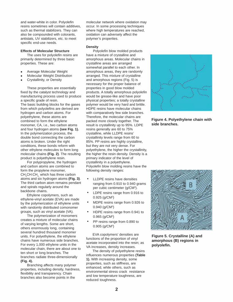
DensityPolyolefin blow molded products
have a mixture of crystalline andamorphous areas. Molecular chains incrystalline areas are arrangedsomewhat parallel to each other. Inamorphous areas, they are randomlyarranged. This mixture of crystallineand amorphous regions (Fig. 5) isnecessary for the proper balance ofproperties in good blow moldedproducts. A totally amorphous polyolefinwould be grease-like and have poorphysical properties; a totally crystallinepolymer would be very hard and brittle.HDPE resins have molecular chainswith comparatively few side branches.Therefore, the molecular chains arepacked more closely together. Theresult is crystallinity up to 95%. LDPEresins generally are 60 to 75%crystalline, while LLDPE resins’crystallinity levels range from 60 to85%. PP resins are highly crystalline,but they are not very dense. Forpolyethylene, the higher the crystallinity,the higher the resin density. Density is aprimary indicator of the level ofcrystallinity in a polyethylene.Polyolefin blow molding resins have thefollowing density ranges:
• LLDPE resins have densitiesranging from 0.910 to 0.940 gramsper cubic centimeter (g/CM3).
• LDPE resins range from 0.916 to0.925 (g/CM3)
• MDPE resins range from 0.926 to0.940 (g/CM3)
• HDPE resins range from 0.941 to0.965 (g/CM3)
• PP resins range from 0.890 to0.905 (g/CM3)
EVA copolymers’ densities arefunctions of the proportion of vinylacetate incorporated into the resin; asVA increases, density increases.
The density of polyethylene resinsinfluences numerous properties (Table1). With increasing density, someproperties, such as stiffness, areenhanced, while others, such asenvironmental stress crack resistanceand low temperature toughness, arereduced toughness.
Figure 4. Polyethylene chain withside branches.
Figure 5. Crystalline (A) andamorphous (B) regions inpolyolefin.
3
Molecular WeightAtoms of different elements, such
as carbon, hydrogen, etc., havedifferent atomic weights. For carbon,the atomic weight is 12, and forhydrogen, it is 1. Thus, the molecularweight of the ethylene unit is the sum ofits six atoms (2 carbon + 4 hydrogen) or28. The molecular weight of anindividual polymer molecule is the sumtotal of teh atomic weights of allcombined ethylene units.
Every polyolefin resin consists of amixture of large and small chains, i.e.,chains of high and low molecularweights. The molecular weight of thepolymer chain generally is in thethousands. The average of these iscalled, quite appropriately, the averagemolecular weight. As averagemolecular weight increases, resintoughness increases. The same holdstrue for telongational properties andenvironmental stress crack resistance(cracking brought on when a moldedpart is subjected to stresses in thepresence of solvents, oils, detergents,etc.).
Melt IndexMelt Index (for polyethylene)and
Melt Flow Rates (for Polypropylene) arean indirect, simple measurement ofthe polymer’s average molecularweight. Polyethylene resin melt indexis expressed in terms of the weight offlow through a standard orifice in a ten-minute time period. This property istested under standard conditions oftemperature and pressure. Melt index(MI) is inversely related to the resin’saverage molecular weight: as averagemolecular weight increases, MIdecreases. Generally, a polyolefin resinwith high molecular weight has a lowMI, and vice versa.
Melt index is an extremelyimportant property since it describesboth the flow of the molten polymer andmany of the polymer’s end-useproperties. The resin’s flow (or output inpounds/hour through an extruder)increases with increasing MI.Polyolefins with lower MI levels cansometimes require higher extrusiontemperatures to make them flow easier.Conversely, most physial properties ofthe solid polymer are enhanced withlower melt index.
Pressure can also influence flowproperties. Two resins may have thesame MI, but different high-pressureflow properties. MI data (Table 2) musttherefore be used in conjunction with
Table 1: General Guide to the Effects of Polyolefin PhysicalProperties on Resin Mechanical Properties andProcessing.
Melt Index DensityIncreases Increases
Chemical Resistance Stays the Same Increases
Clarity Increases Decreases
Elongation at Break Decreases Decreases
Flexibility Stays the Same Decreases
Gloss Improves Stays the Same
Heat Resistance Decreases Increases(softening point)
Impermeability to Gases/Liquids Stays the Same Increases
Low Temperature Flexibiity Decreases Decreases
Melt Viscosity Decreases Stays the Same
Mechanical Flex Life Decreases Decreases
Stress Crack Resistance Decreases Decreases
Tensile Strength at Break Decreases Increases
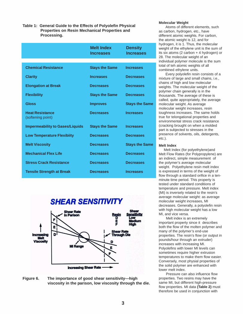
Figure 6. The importance of good shear sensitivity—highviscosity in the parison, low viscosity through the die.
4
other properties, such as molecularweight distribution, to fully characterizethe processability of a resin.
Shear SensitivityMelt index and density are two
extremely useful numbers fordescribing a polyethylene resin; a thirdis “shear sensitivity.” The viscosity ofmelted HDPE appears to changedepending on how rapidly it isundergoing shear, i.e, how fast it isbeing pushed through the extruder ordie. Under moderate rates of shear,HDPE is moderately viscous. When it isforced at high speed through a narrowdie gap, the HDPE melt is sheared at afast rate; at this point it appears to havea low viscosity. Then, when it hangsfrom the die as a blow molding parison,under practically no shear, the sameHDPE appears to be very viscous.
All HDPE resins show varyingdegrees of shear sensitivity; in general,the faster the shear rate, the lower theapparent viscosity. HDPE resins withhigh shear sensitivity require lesspower and heat input to yield fasterextrusion rates (Fig. 6).
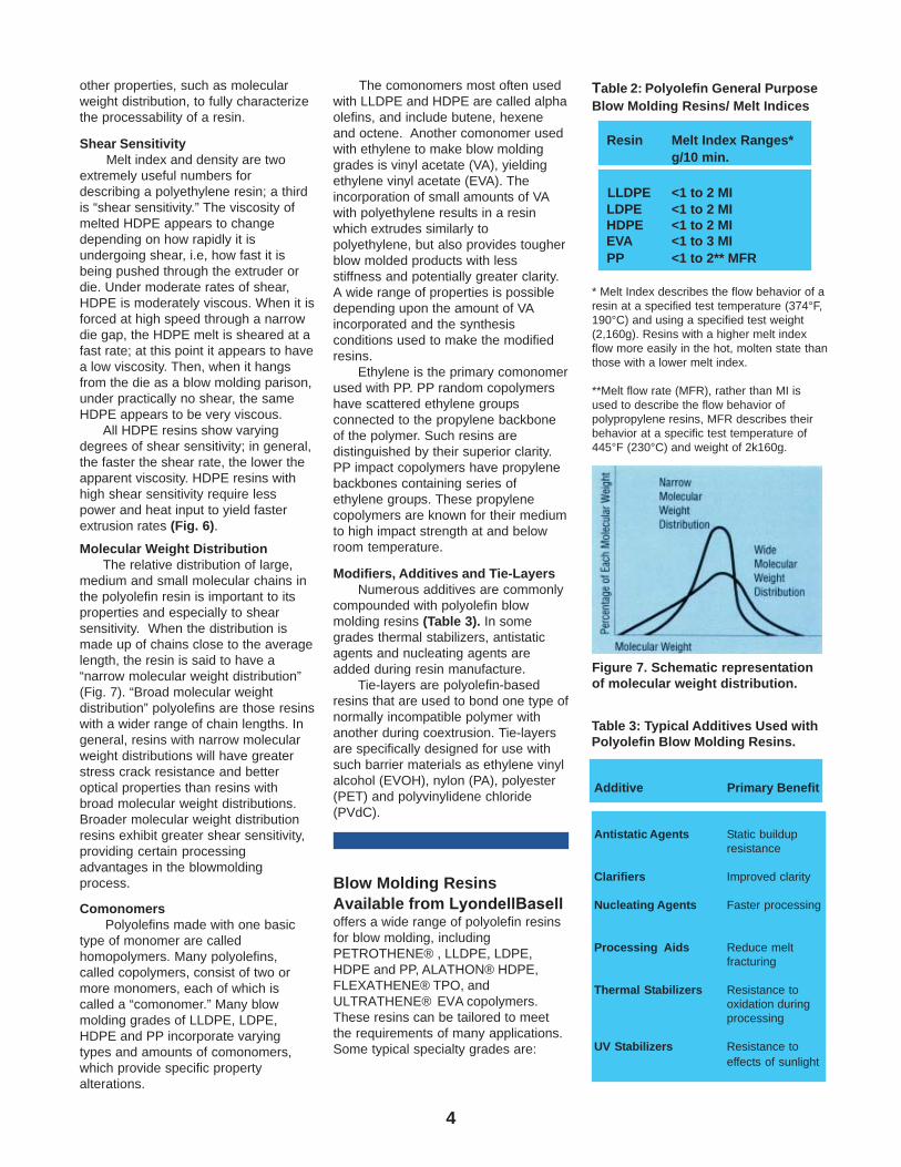
Molecular Weight DistributionThe relative distribution of large,
medium and small molecular chains inthe polyolefin resin is important to itsproperties and especially to shearsensitivity. When the distribution ismade up of chains close to the averagelength, the resin is said to have a“narrow molecular weight distribution”(Fig. 7). “Broad molecular weightdistribution” polyolefins are those resinswith a wider range of chain lengths. Ingeneral, resins with narrow molecularweight distributions will have greaterstress crack resistance and betteroptical properties than resins withbroad molecular weight distributions.Broader molecular weight distributionresins exhibit greater shear sensitivity,providing certain processingadvantages in the blowmoldingprocess.
ComonomersPolyolefins made with one basic
type of monomer are calledhomopolymers. Many polyolefins,called copolymers, consist of two ormore monomers, each of which iscalled a “comonomer.” Many blowmolding grades of LLDPE, LDPE,HDPE and PP incorporate varyingtypes and amounts of comonomers,which provide specific propertyalterations.
The comonomers most often usedwith LLDPE and HDPE are called alphaolefins, and include butene, hexeneand octene. Another comonomer usedwith ethylene to make blow moldinggrades is vinyl acetate (VA), yieldingethylene vinyl acetate (EVA). Theincorporation of small amounts of VAwith polyethylene results in a resinwhich extrudes similarly topolyethylene, but also provides tougherblow molded products with lessstiffness and potentially greater clarity.A wide range of properties is possibledepending upon the amount of VAincorporated and the synthesisconditions used to make the modifiedresins.
Ethylene is the primary comonomerused with PP. PP random copolymershave scattered ethylene groupsconnected to the propylene backboneof the polymer. Such resins aredistinguished by their superior clarity.PP impact copolymers have propylenebackbones containing series ofethylene groups. These propylenecopolymers are known for their mediumto high impact strength at and belowroom temperature.
Modifiers, Additives and Tie-LayersNumerous additives are commonly
compounded with polyolefin blowmolding resins (Table 3). In somegrades thermal stabilizers, antistaticagents and nucleating agents areadded during resin manufacture.
Tie-layers are polyolefin-basedresins that are used to bond one type ofnormally incompatible polymer withanother during coextrusion. Tie-layersare specifically designed for use withsuch barrier materials as ethylene vinylalcohol (EVOH), nylon (PA), polyester(PET) and polyvinylidene chloride(PVdC).
Blow Molding ResinsAvailable from LyondellBaselloffers a wide range of polyolefin resins for blow molding, including PETROTHENE® , LLDPE, LDPE, HDPE and PP, ALATHON® HDPE, FLEXATHENE® TPO, and ULTRATHENE® EVA copolymers. These resins can be tailored to meet the requirements of many applications. Some typical specialty grades are:
Table 2: Polyolefin General PurposeBlow Molding Resins/ Melt Indices
Resin Melt Index Ranges*g/10 min.
LLDPE <1 to 2 MI LDPE <1 to 2 MI HDPE <1 to 2 MI EVA <1 to 3 MI PP <1 to 2** MFR
* Melt Index describes the flow behavior of aresin at a specified test temperature (374°F,190°C) and using a specified test weight(2,160g). Resins with a higher melt indexflow more easily in the hot, molten state thanthose with a lower melt index.
**Melt flow rate (MFR), rather than MI isused to describe the flow behavior ofpolypropylene resins, MFR describes theirbehavior at a specific test temperature of445°F (230°C) and weight of 2k160g.
Table 3: Typical Additives Used withPolyolefin Blow Molding Resins.
Figure 7. Schematic representationof molecular weight distribution.
Additive Primary Benefit
Antistatic Agents Static buildupresistance
Clarifiers Improved clarity
Nucleating Agents Faster processing
Processing Aids Reduce meltfracturing
Thermal Stabilizers Resistance tooxidation duringprocessing
UV Stabilizers Resistance toeffects of sunlight
5
• High Clarity Polypropylene• Injection Blow Molding HDPE• High Stiffness HDPE• Excellent ESCR HDPE• Soft, Flexible LDPE• Injection Blow Molding PP• High Clarity EVA
In summary, polyolefin resins withdistinctly different properties can be made by varying the three basic molecular properties of density, molecular weight and melt viscosity and by adding comonomers and additives. Processors can work closely with their LyondellBasell polyolefins sales representatives to determine which polyethylene, polypropylene or EVA best meets their needs.
Shipping and HandlingPolyolefin Blow MoldingResins
It is of utmost importance to keep polyolefin resins clean. Contaminated resins can produce poor products. Polyolefin resins are shipped to processors by LyondellBasell in rail cars, hopper trucks, 1000- and 1500-pound polyethylene-lined corrugated boxes and 50-pound plastic bags. Strict quality control throughout resin manufacture and subsequent handling, right through delivery to the customer, ensures the cleanliness of the products.
When bulk containers aredelivered, the processor must use
clean, efficient procedures forunloading the resin. Maintenance of thein-plant materials handling system alsois essential. When bags and boxes areused, special care must be taken inopening the containers, as well ascovering them as they are unloadedand used.
Stringent precautions must also betaken when using reground resin,whether as a blend or alone, to keep itfree of contamination. Wheneverpossible, the regrind should be used asit is generated. When this is notpossible, the scrap should be collectedin a closed system and recycled withthe same precautions taken for virginresin.
How Polyolefin Resins areMade
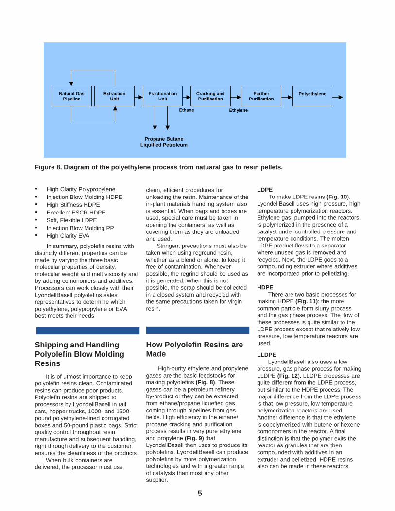
High-purity ethylene and propylene gases are the basic feedstocks for making polyolefins (Fig. 8). These gases can be a petroleum refinery by-product or they can be extracted from ethane/propane liquefied gas coming through pipelines from gas fields. High efficiency in the ethane/propane cracking and purification process results in very pure ethylene and propylene (Fig. 9) that LyondellBasell then uses to produce its polyolefins. LyondellBasell can produce polyolefins by more polymerization technologies and with a greater range of catalysts than most any other supplier.
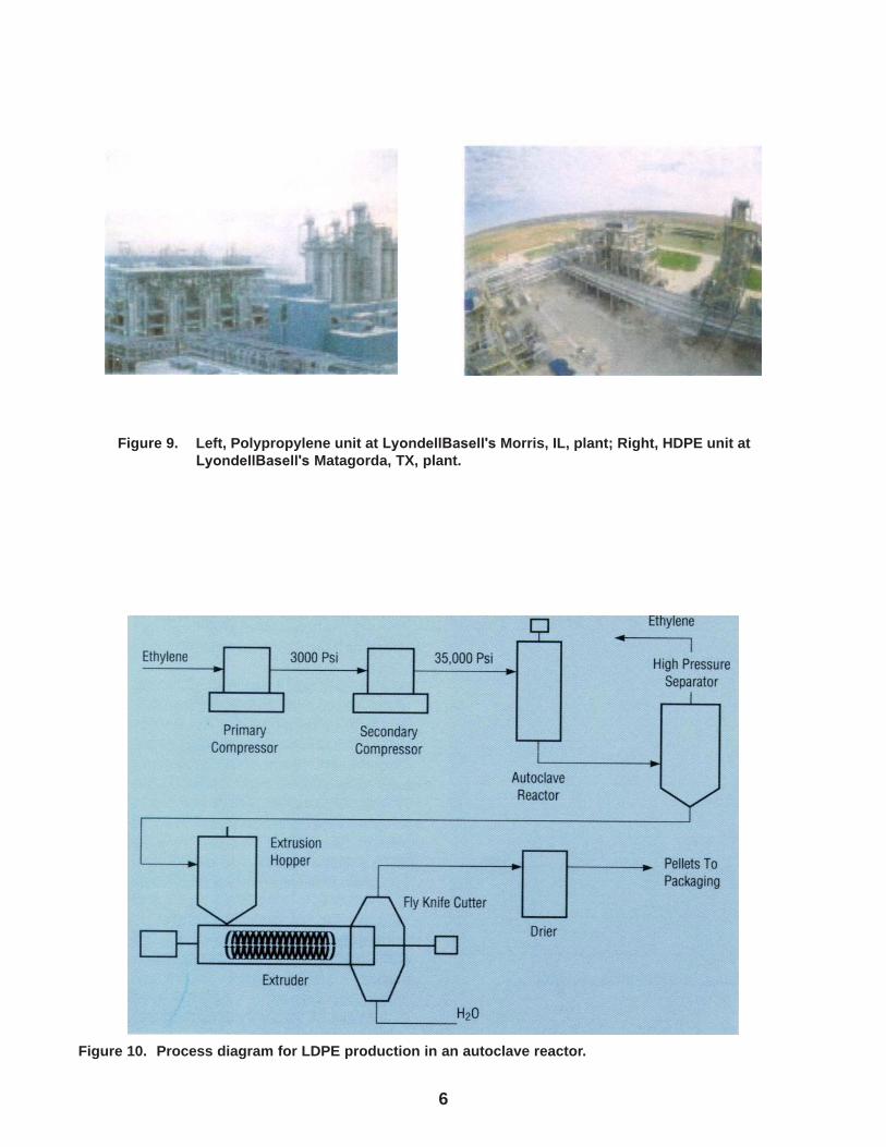
LDPETo make LDPE resins (Fig. 10),
LyondellBasell uses high pressure, high temperature polymerization reactors. Ethylene gas, pumped into the reactors, is polymerized in the presence of a catalyst under controlled pressure and temperature conditions. The molten LDPE product flows to a separator where unused gas is removed and recycled. Next, the LDPE goes to a compounding extruder where additives are incorporated prior to pelletizing.
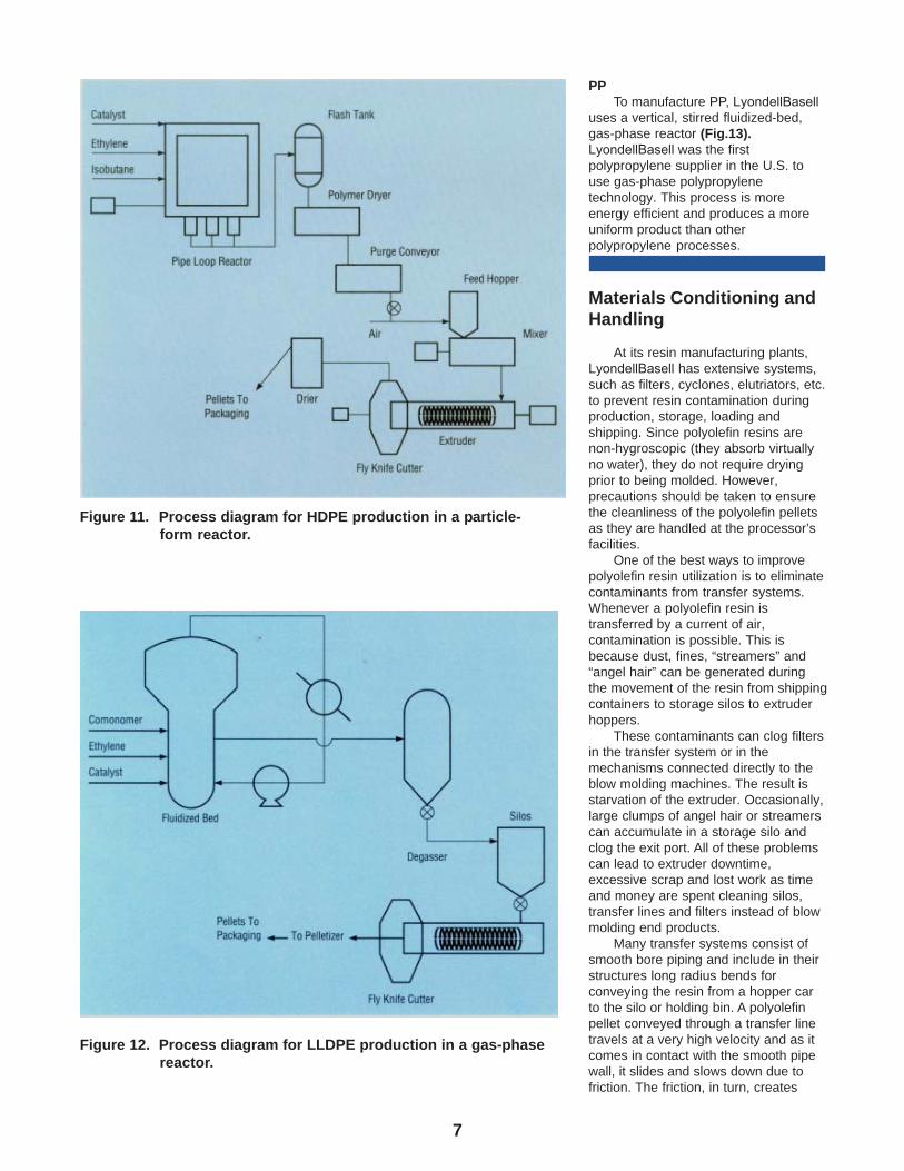
HDPEThere are two basic processes for
making HDPE (Fig. 11): the more common particle form slurry process and the gas phase process. The flow of these processes is quite similar to the LDPE process except that relatively low pressure, low temperature reactors are used.
LLDPELyondellBasell also uses a low
pressure, gas phase process for making LLDPE (Fig. 12). LLDPE processes are quite different from the LDPE process, but similar to the HDPE process. The major difference from the LDPE process is that low pressure, low temperature polymerization reactors are used. Another difference is that the ethylene is copolymerized with butene or hexene comonomers in the reactor. A final distinction is that the polymer exits the reactor as granules that are then compounded with additives in an extruder and pelletized. HDPE resins also can be made in these reactors.
Figure 8. Diagram of the polyethylene process from natuaral gas to resin pellets.
EthyleneEthane
Natural GasPipeline
ExtractionUnit
FractionationUnit
Cracking andPurification
FurtherPurification
Polyethylene
Propane ButaneLiquified Petroleum
6
Figure 9. Left, Polypropylene unit at LyondellBasell's Morris, IL, plant; Right, HDPE unit atLyondellBasell's Matagorda, TX, plant.
Figure 10. Process diagram for LDPE production in an autoclave reactor.
7
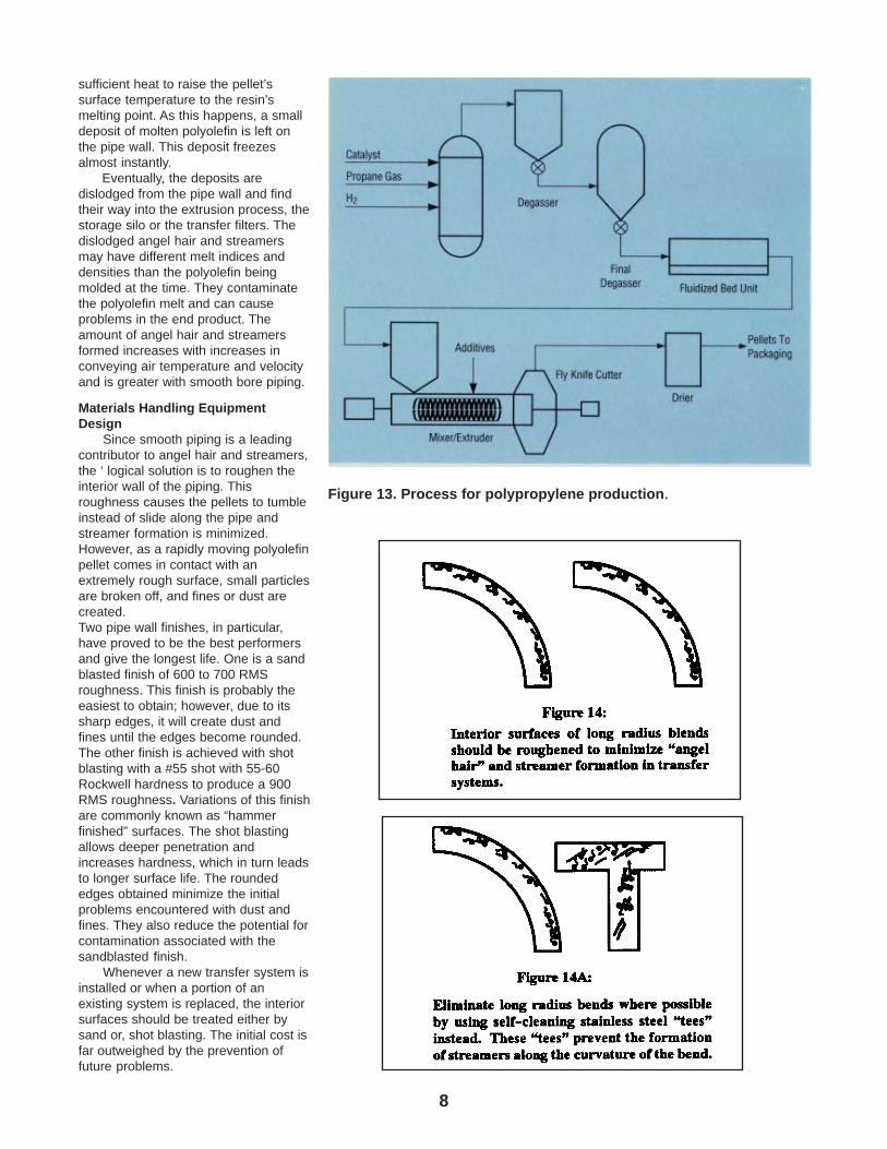
PPTo manufacture PP, LyondellBasell
uses a vertical, stirred fluidized-bed,gas-phase reactor (Fig.13). LyondellBasell was the first polypropylene supplier in the U.S. to use gas-phase polypropylene technology. This process is more energy efficient and produces a more uniform product than other polypropylene processes.
Materials Conditioning andHandling
At its resin manufacturing plants, LyondellBasell has extensive systems, such as filters, cyclones, elutriators, etc. to prevent resin contamination during production, storage, loading and shipping. Since polyolefin resins are non-hygroscopic (they absorb virtually no water), they do not require drying prior to being molded. However, precautions should be taken to ensure the cleanliness of the polyolefin pellets as they are handled at the processor’s facilities.
One of the best ways to improve polyolefin resin utilization is to eliminate contaminants from transfer systems. Whenever a polyolefin resin is transferred by a current of air, contamination is possible. This is because dust, fines, “streamers” and “angel hair” can be generated during the movement of the resin from shipping containers to storage silos to extruder hoppers.
These contaminants can clog filters in the transfer system or in the mechanisms connected directly to the blow molding machines. The result is starvation of the extruder. Occasionally, large clumps of angel hair or streamers can accumulate in a storage silo and clog the exit port. All of these problems can lead to extruder downtime, excessive scrap and lost work as time and money are spent cleaning silos, transfer lines and filters instead of blow molding end products.
Many transfer systems consist of smooth bore piping and include in their structures long radius bends for conveying the resin from a hopper car to the silo or holding bin. A polyolefin pellet conveyed through a transfer line travels at a very high velocity and as it comes in contact with the smooth pipe wall, it slides and slows down due to friction. The friction, in turn, creates
Figure 11. Process diagram for HDPE production in a particle-form reactor.
Figure 12. Process diagram for LLDPE production in a gas-phasereactor.
8
sufficient heat to raise the pellet’ssurface temperature to the resin’smelting point. As this happens, a smalldeposit of molten polyolefin is left onthe pipe wall. This deposit freezesalmost instantly.
Eventually, the deposits aredislodged from the pipe wall and findtheir way into the extrusion process, thestorage silo or the transfer filters. Thedislodged angel hair and streamersmay have different melt indices anddensities than the polyolefin beingmolded at the time. They contaminatethe polyolefin melt and can causeproblems in the end product. Theamount of angel hair and streamersformed increases with increases inconveying air temperature and velocityand is greater with smooth bore piping.
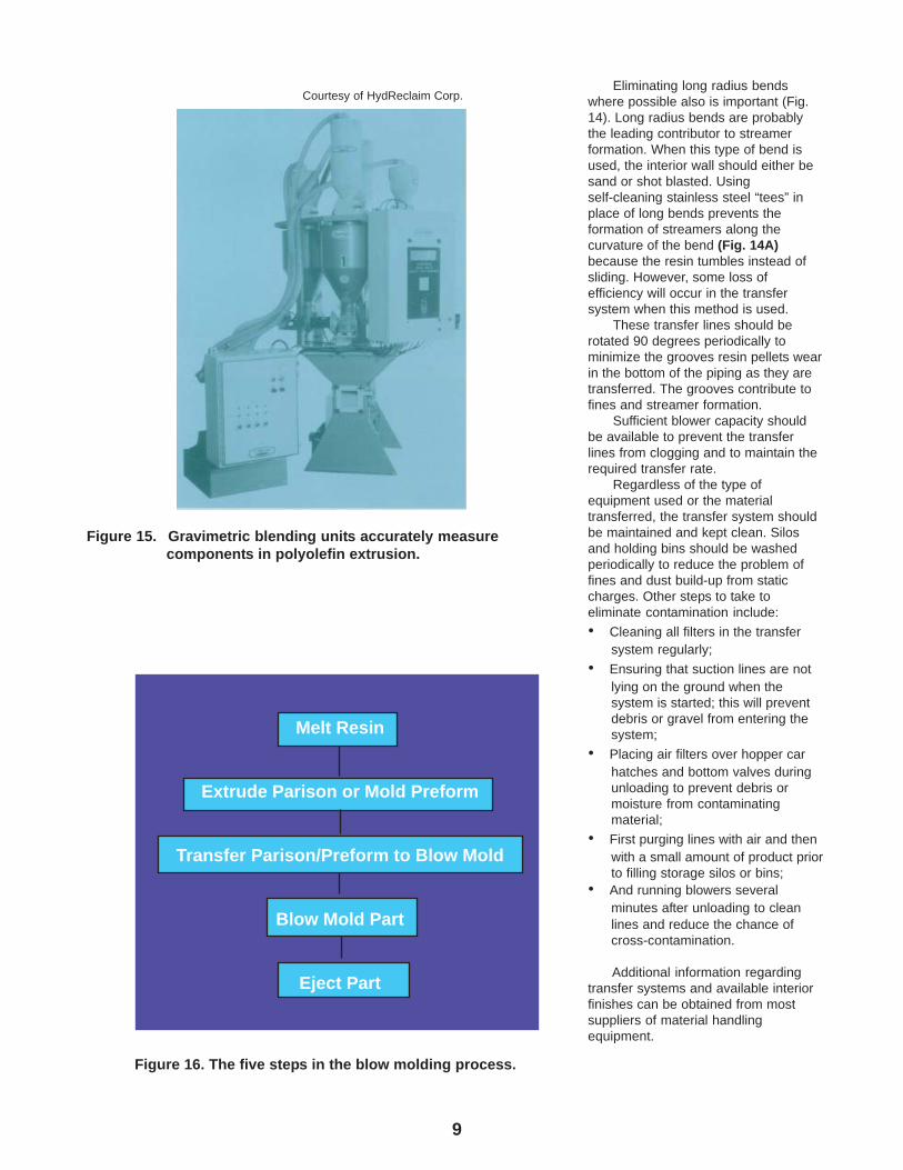
Materials Handling EquipmentDesign
Since smooth piping is a leadingcontributor to angel hair and streamers,the ‘ logical solution is to roughen theinterior wall of the piping. Thisroughness causes the pellets to tumbleinstead of slide along the pipe andstreamer formation is minimized.However, as a rapidly moving polyolefinpellet comes in contact with anextremely rough surface, small particlesare broken off, and fines or dust arecreated.Two pipe wall finishes, in particular,have proved to be the best performersand give the longest life. One is a sandblasted finish of 600 to 700 RMSroughness. This finish is probably theeasiest to obtain; however, due to itssharp edges, it will create dust andfines until the edges become rounded.The other finish is achieved with shotblasting with a #55 shot with 55-60Rockwell hardness to produce a 900RMS roughness. Variations of this finishare commonly known as “hammerfinished” surfaces. The shot blastingallows deeper penetration andincreases hardness, which in turn leadsto longer surface life. The roundededges obtained minimize the initialproblems encountered with dust andfines. They also reduce the potential forcontamination associated with thesandblasted finish.
Whenever a new transfer system isinstalled or when a portion of anexisting system is replaced, the interiorsurfaces should be treated either bysand or, shot blasting. The initial cost isfar outweighed by the prevention offuture problems.
Figure 13. Process for polypropylene production.
9
Eliminating long radius bendswhere possible also is important (Fig.14). Long radius bends are probablythe leading contributor to streamerformation. When this type of bend isused, the interior wall should either besand or shot blasted. Usingself-cleaning stainless steel “tees” inplace of long bends prevents theformation of streamers along thecurvature of the bend (Fig. 14A)because the resin tumbles instead ofsliding. However, some loss ofefficiency will occur in the transfersystem when this method is used.
These transfer lines should berotated 90 degrees periodically tominimize the grooves resin pellets wearin the bottom of the piping as they aretransferred. The grooves contribute tofines and streamer formation.
Sufficient blower capacity shouldbe available to prevent the transferlines from clogging and to maintain therequired transfer rate.
Regardless of the type ofequipment used or the materialtransferred, the transfer system shouldbe maintained and kept clean. Silosand holding bins should be washedperiodically to reduce the problem offines and dust build-up from staticcharges. Other steps to take toeliminate contamination include:
• Cleaning all filters in the transfersystem regularly;
• Ensuring that suction lines are notlying on the ground when thesystem is started; this will preventdebris or gravel from entering thesystem;
• Placing air filters over hopper carhatches and bottom valves duringunloading to prevent debris ormoisture from contaminatingmaterial;
• First purging lines with air and thenwith a small amount of product priorto filling storage silos or bins;
• And running blowers severalminutes after unloading to cleanlines and reduce the chance ofcross-contamination.
Additional information regardingtransfer systems and available interiorfinishes can be obtained from mostsuppliers of material handlingequipment.
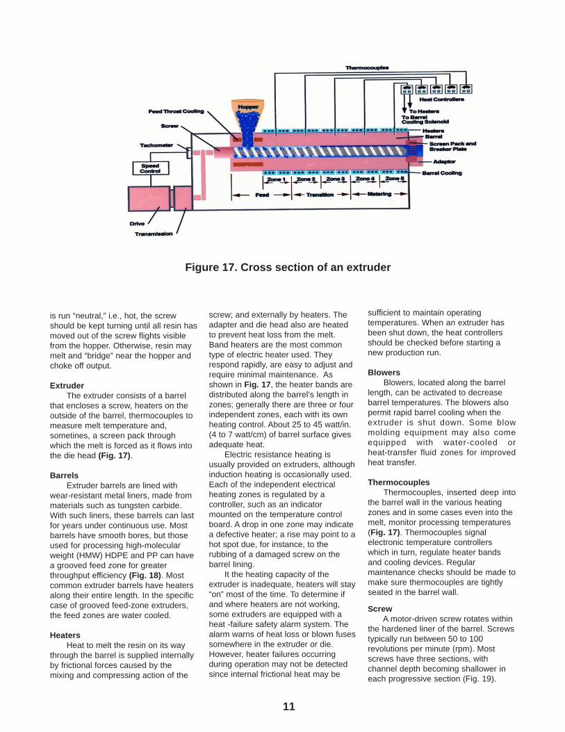
Figure 16. The five steps in the blow molding process.
Melt Resin
Extrude Parison or Mold Preform
Transfer Parison/Preform to Blow Mold
Blow Mold Part
Eject Part
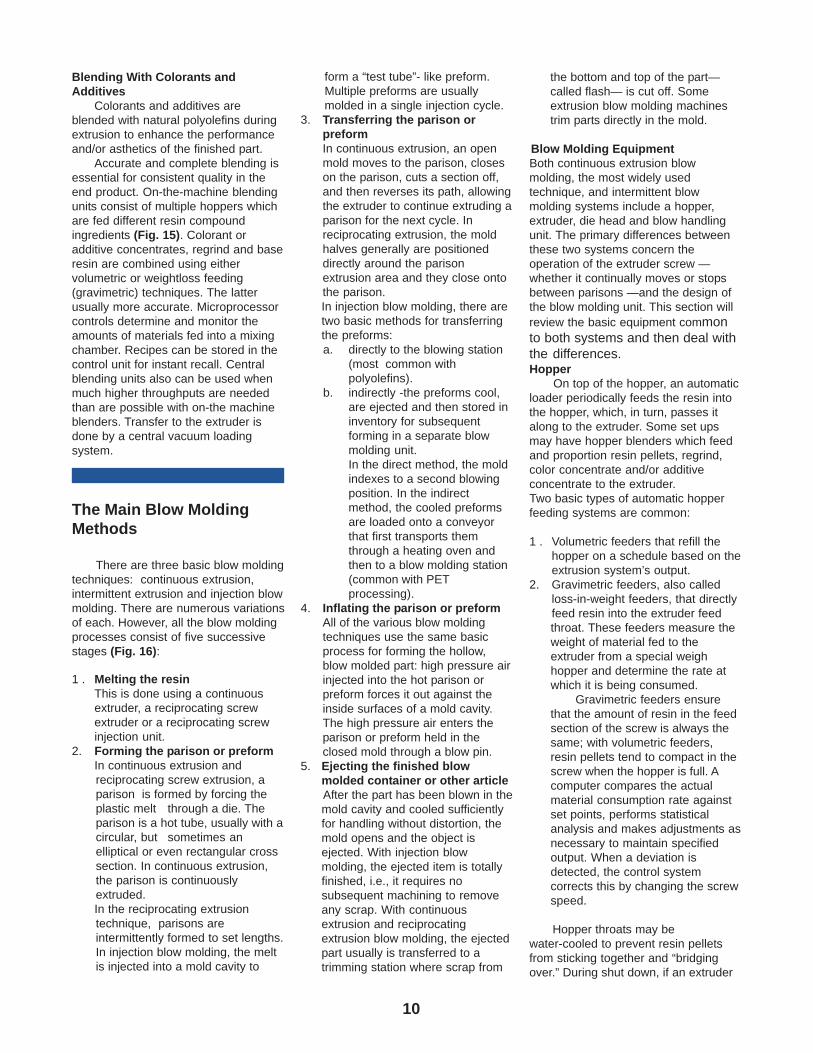
Figure 15. Gravimetric blending units accurately measurecomponents in polyolefin extrusion.
Courtesy of HydReclaim Corp.
10
Blending With Colorants andAdditives
Colorants and additives areblended with natural polyolefins duringextrusion to enhance the performanceand/or asthetics of the finished part.
Accurate and complete blending isessential for consistent quality in theend product. On-the-machine blendingunits consist of multiple hoppers whichare fed different resin compoundingredients (Fig. 15). Colorant oradditive concentrates, regrind and baseresin are combined using eithervolumetric or weightloss feeding(gravimetric) techniques. The latterusually more accurate. Microprocessorcontrols determine and monitor theamounts of materials fed into a mixingchamber. Recipes can be stored in thecontrol unit for instant recall. Centralblending units also can be used whenmuch higher throughputs are neededthan are possible with on-the machineblenders. Transfer to the extruder isdone by a central vacuum loadingsystem.
The Main Blow MoldingMethods
There are three basic blow moldingtechniques: continuous extrusion,intermittent extrusion and injection blowmolding. There are numerous variationsof each. However, all the blow moldingprocesses consist of five successivestages (Fig. 16):
1 . Melting the resinThis is done using a continuousextruder, a reciprocating screwextruder or a reciprocating screwinjection unit.
2. Forming the parison or preformIn continuous extrusion andreciprocating screw extrusion, aparison is formed by forcing theplastic melt through a die. Theparison is a hot tube, usually with acircular, but sometimes anelliptical or even rectangular crosssection. In continuous extrusion,the parison is continuouslyextruded.In the reciprocating extrusiontechnique, parisons areintermittently formed to set lengths.In injection blow molding, the meltis injected into a mold cavity to
form a “test tube”- like preform.Multiple preforms are usuallymolded in a single injection cycle.
3. Transferring the parison orpreformIn continuous extrusion, an openmold moves to the parison, closeson the parison, cuts a section off,and then reverses its path, allowingthe extruder to continue extruding aparison for the next cycle. Inreciprocating extrusion, the moldhalves generally are positioneddirectly around the parisonextrusion area and they close ontothe parison.In injection blow molding, there aretwo basic methods for transferringthe preforms:a. directly to the blowing station
(most common withpolyolefins).
b. indirectly -the preforms cool,are ejected and then stored ininventory for subsequentforming in a separate blowmolding unit.In the direct method, the moldindexes to a second blowingposition. In the indirectmethod, the cooled preformsare loaded onto a conveyorthat first transports themthrough a heating oven andthen to a blow molding station(common with PETprocessing).
4. Inflating the parison or preformAll of the various blow moldingtechniques use the same basicprocess for forming the hollow,blow molded part: high pressure airinjected into the hot parison orpreform forces it out against theinside surfaces of a mold cavity.The high pressure air enters theparison or preform held in theclosed mold through a blow pin.
5. Ejecting the finished blowmolded container or other articleAfter the part has been blown in themold cavity and cooled sufficientlyfor handling without distortion, themold opens and the object isejected. With injection blowmolding, the ejected item is totallyfinished, i.e., it requires nosubsequent machining to removeany scrap. With continuousextrusion and reciprocatingextrusion blow molding, the ejectedpart usually is transferred to atrimming station where scrap from
the bottom and top of the part—called flash— is cut off. Someextrusion blow molding machinestrim parts directly in the mold.
Blow Molding EquipmentBoth continuous extrusion blowmolding, the most widely usedtechnique, and intermittent blowmolding systems include a hopper,extruder, die head and blow handlingunit. The primary differences betweenthese two systems concern theoperation of the extruder screw —whether it continually moves or stopsbetween parisons —and the design ofthe blow molding unit. This section willreview the basic equipment commonto both systems and then deal withthe differences.Hopper
On top of the hopper, an automaticloader periodically feeds the resin intothe hopper, which, in turn, passes italong to the extruder. Some set upsmay have hopper blenders which feedand proportion resin pellets, regrind,color concentrate and/or additiveconcentrate to the extruder.Two basic types of automatic hopperfeeding systems are common:
1 . Volumetric feeders that refill thehopper on a schedule based on theextrusion system’s output.
2. Gravimetric feeders, also calledloss-in-weight feeders, that directlyfeed resin into the extruder feedthroat. These feeders measure theweight of material fed to theextruder from a special weighhopper and determine the rate atwhich it is being consumed.
Gravimetric feeders ensurethat the amount of resin in the feedsection of the screw is always thesame; with volumetric feeders,resin pellets tend to compact in thescrew when the hopper is full. Acomputer compares the actualmaterial consumption rate againstset points, performs statisticalanalysis and makes adjustments asnecessary to maintain specifiedoutput. When a deviation isdetected, the control systemcorrects this by changing the screwspeed.
Hopper throats may bewater-cooled to prevent resin pelletsfrom sticking together and “bridgingover.” During shut down, if an extruder
11
is run “neutral,” i.e., hot, the screwshould be kept turning until all resin hasmoved out of the screw flights visiblefrom the hopper. Otherwise, resin maymelt and “bridge” near the hopper andchoke off output.
ExtruderThe extruder consists of a barrel
that encloses a screw, heaters on theoutside of the barrel, thermocouples tomeasure melt temperature and,sometines, a screen pack throughwhich the melt is forced as it flows intothe die head (Fig. 17).
BarrelsExtruder barrels are lined with
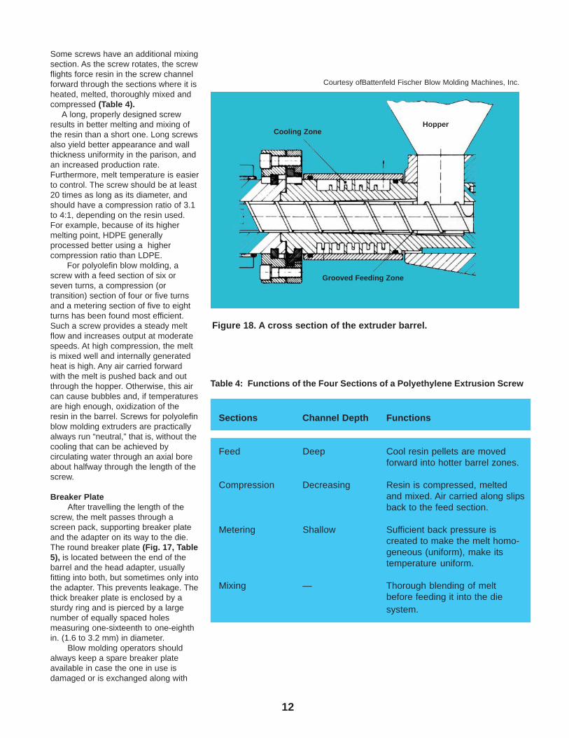
wear-resistant metal liners, made frommaterials such as tungsten carbide.With such liners, these barrels can lastfor years under continuous use. Mostbarrels have smooth bores, but thoseused for processing high-molecularweight (HMW) HDPE and PP can havea grooved feed zone for greaterthroughput efficiency (Fig. 18). Mostcommon extruder barrels have heatersalong their entire length. In the specificcase of grooved feed-zone extruders,the feed zones are water cooled.
HeatersHeat to melt the resin on its way
through the barrel is supplied internallyby frictional forces caused by themixing and compressing action of the
screw; and externally by heaters. Theadapter and die head also are heatedto prevent heat loss from the melt.Band heaters are the most commontype of electric heater used. Theyrespond rapidly, are easy to adjust andrequire minimal maintenance. Asshown in Fig. 17, the heater bands aredistributed along the barrel’s length inzones; generally there are three or fourindependent zones, each with its ownheating control. About 25 to 45 watt/in.(4 to 7 watt/cm) of barrel surface givesadequate heat.
Electric resistance heating isusually provided on extruders, althoughinduction heating is occasionally used.Each of the independent electricalheating zones is regulated by acontroller, such as an indicatormounted on the temperature controlboard. A drop in one zone may indicatea defective heater; a rise may point to ahot spot due, for instance, to therubbing of a damaged screw on thebarrel lining.
It the heating capacity of theextruder is inadequate, heaters will stay“on” most of the time. To determine ifand where heaters are not working,some extruders are equipped with aheat -failure safety alarm system. Thealarm warns of heat loss or blown fusessomewhere in the extruder or die.However, heater failures occurringduring operation may not be detectedsince internal frictional heat may be
Figure 17. Cross section of an extruder
sufficient to maintain operatingtemperatures. When an extruder hasbeen shut down, the heat controllersshould be checked before starting anew production run.
BlowersBlowers, located along the barrel
length, can be activated to decreasebarrel temperatures. The blowers alsopermit rapid barrel cooling when theextruder is shut down. Some blowmolding equipment may also comeequipped with water-cooled orheat-transfer fluid zones for improvedheat transfer.
ThermocouplesThermocouples, inserted deep into
the barrel wall in the various heatingzones and in some cases even into themelt, monitor processing temperatures(Fig. 17). Thermocouples signalelectronic temperature controllerswhich in turn, regulate heater bandsand cooling devices. Regularmaintenance checks should be made tomake sure thermocouples are tightlyseated in the barrel wall.
ScrewA motor-driven screw rotates within
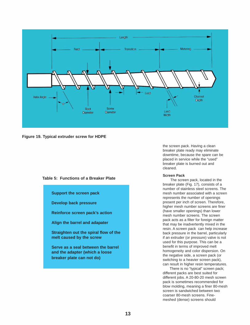
the hardened liner of the barrel. Screwstypically run between 50 to 100revolutions per minute (rpm). Mostscrews have three sections, withchannel depth becoming shallower ineach progressive section (Fig. 19).
12
Some screws have an additional mixingsection. As the screw rotates, the screwflights force resin in the screw channelforward through the sections where it isheated, melted, thoroughly mixed andcompressed (Table 4).
A long, properly designed screwresults in better melting and mixing ofthe resin than a short one. Long screwsalso yield better appearance and wallthickness uniformity in the parison, andan increased production rate.Furthermore, melt temperature is easierto control. The screw should be at least20 times as long as its diameter, andshould have a compression ratio of 3.1to 4:1, depending on the resin used.For example, because of its highermelting point, HDPE generallyprocessed better using a highercompression ratio than LDPE.
For polyolefin blow molding, ascrew with a feed section of six orseven turns, a compression (ortransition) section of four or five turnsand a metering section of five to eightturns has been found most efficient.Such a screw provides a steady meltflow and increases output at moderatespeeds. At high compression, the meltis mixed well and internally generatedheat is high. Any air carried forwardwith the melt is pushed back and outthrough the hopper. Otherwise, this aircan cause bubbles and, if temperaturesare high enough, oxidization of theresin in the barrel. Screws for polyolefinblow molding extruders are practicallyalways run “neutral,” that is, without thecooling that can be achieved bycirculating water through an axial boreabout halfway through the length of thescrew.
Breaker PlateAfter travelling the length of the
screw, the melt passes through ascreen pack, supporting breaker plateand the adapter on its way to the die.The round breaker plate (Fig. 17, Table5), is located between the end of thebarrel and the head adapter, usuallyfitting into both, but sometimes only intothe adapter. This prevents leakage. Thethick breaker plate is enclosed by asturdy ring and is pierced by a largenumber of equally spaced holesmeasuring one-sixteenth to one-eighthin. (1.6 to 3.2 mm) in diameter.
Blow molding operators shouldalways keep a spare breaker plateavailable in case the one in use isdamaged or is exchanged along with
Table 4: Functions of the Four Sections of a Polyethylene Extrusion Screw
Sections Channel Depth Functions
Feed Deep Cool resin pellets are movedforward into hotter barrel zones.
Compression Decreasing Resin is compressed, meltedand mixed. Air carried along slipsback to the feed section.
Metering Shallow Sufficient back pressure iscreated to make the melt homo-geneous (uniform), make itstemperature uniform.
Mixing — Thorough blending of meltbefore feeding it into the diesystem.
Figure 18. A cross section of the extruder barrel.
Grooved Feeding Zone
Cooling ZoneHopper
Courtesy ofBattenfeld Fischer Blow Molding Machines, Inc.
13
the screen pack. Having a cleanbreaker plate ready may eliminatedowntime, because the spare can beplaced in service while the “used”breaker plate is burned out andcleaned.
Screen PackThe screen pack, located in the
breaker plate (Fig. 17), consists of anumber of stainless steel screens. Themesh number associated with a screenrepresents the number of openingspresent per inch of screen. Therefore,higher mesh number screens are finer(have smaller openings) than lowermesh number screens. The screenpack acts as a filter for foreign matterthat may be inadvertently mixed in theresin. A screen pack can help increaseback pressure in the barrel, particularlyif an extruder (or pressure) valve is notused for this purpose. This can be abenefit in terms of improved melthomogeneity and color dispersion. Onthe negative side, a screen pack (orswitching to a heavier screen pack),can result in higher resin temperatures.
There is no “typical” screen pack;different packs are best suited fordifferent jobs. A 20-80-20 mesh screenpack is sometimes recommended forblow molding, meaning a finer 80-meshscreen is sandwiched between twocoarser 80-mesh screens. Fine-meshed (dense) screens should
Table 5: Functions of a Breaker Plate
Support the screen pack
Develop back pressure
Reinforce screen pack’s action
Align the barrel and adapater
Straighten out the spiral flow of themelt caused by the screw
Serve as a seal between the barreland the adapter (which a loosebreaker plate can not do)
Figure 19. Typical extruder screw for HDPE
14
generally be located between coarserscreens as this offers better physicalsupport. The temperature of the meltmay be raised slightly by using a muchheavier screen pack (more or finerscreens, or both) which, by increasingthe back pressure, may also generateadditional frictional heat.
Always use stainless-steelscreens, never copper screens,although they are less expensive.Copper is too soft for such a highpressure application; moreover, it mayoxidize and contaminate the resin. Ahinged or swing-gate collar may beused to attach the adapter tightly to thebarrel head and to facilitate screenpack changes. Screen packs do needto be replaced on a periodic basis.
Automatic Screen ChangersAutomatic screen changers, which
have either a continuous screen bandor rotary units that index when exposedsections become clogged, can be usedwith continuous extrusion blow moldingmachines. The indexing occurs withoutinterrupting the melt flow. Theseeliminate downtime necessary formanual screen changes.
Pressure valvesPressure valves permit a constant
check on internal pressures; thesehave a significant effect on melttemperatures. Two types of pressurevalves are common:
1. The internal pressure valve is amovable screw that can beadjusted forward or backward toincrease or decrease pressure.Moving thescrew varies the size ofthe opening between the end of thescrew and the breaker plate andadapter.
2. External pressure valves use a pinarrangement that varies the size ofthe opening at the extruder’sadapter, thereby varying pressure.At the end of the extruder barrel,between the melt screen and theparison die head, there is anadapter (Fig. 17) that constrictsand guides the resin melt flow in astreamlined path with a minimumof resin hangup.
Melt PumpsMelt pumps, also called gear
pumps, can be attached between theend of the extruder and the die head togreatly increase melt quality. Forcontinuous extrusion multilayer blow
molding, these units can deliver astable, surge-free melt output andprovide excellent layer uniformity.These benefits are particularlyimportant for thin barrier layers andadhesive tie-layers found in coextrusionblow molding.
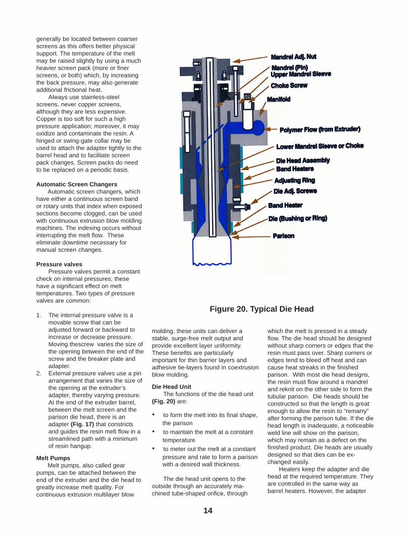
Die Head UnitThe functions of the die head unit
(Fig. 20) are:
• to form the melt into its final shape,the parison
• to maintain the melt at a constanttemperature
• to meter out the melt at a constantpressure and rate to form a parisonwith a desired wall thickness.
The die head unit opens to theoutside through an accurately ma-chined tube-shaped orifice, through
which the melt is pressed in a steadyflow. The die head should be designedwithout sharp corners or edges that theresin must pass over. Sharp corners oredges tend to bleed off heat and cancause heat streaks in the finishedparison. With most die head designs,the resin must flow around a mandreland reknit on the other side to form thetubular parison. Die heads should beconstructed so that the length is greatenough to allow the resin to “remarry”after forming the parison tube. If the diehead length is inadequate, a noticeableweld line will show on the parison,which may remain as a defect on thefinished product. Die heads are usuallydesigned so that dies can be ex-changed easily.
Heaters keep the adapter and diehead at the required temperature. Theyare controlled in the same way asbarrel heaters. However, the adapter
Figure 20. Typical Die Head
15
and die head heaters maintain melttemperature and should not be used toincrease it. Melt temperature at the diehead, where the parison forms, rangesfrom 290 to 32°F (145 to 165°C) forLDPE; 350 to 400°F (175 to 205°C) forHDPE; and 375° to 425°F (1900 to220°C) for PP (PP homopolymers haveslightly higher, melting temperaturesthan random copolymers). Resins withlower melt indices require melttemperatures at the higher end of theseranges than higher melt index resins.
Generally, LDPE resins for blowmolding have melt indices below 2 g/10min.; HDPE, below 1.0 g/10 min.; andPP, melt flow rates below 2 g/10 min. Ifresin melt temperatures are too low, theparison will be cloudy or dull inappearance and may also show signs ofmelt fracturing or aligatoring. A parisonof this type will not be hot enough toyield good weld lines at the pinch-offareas. On the other hand, if the melttemperature is too high, the parison willlook clear, have glossy areas and mayemit smoke. The hot parison will bestringy and tend to stretch easily,resulting in thin areas. Pinch-offproblems may also occur, as well asextremely thin weld lines.
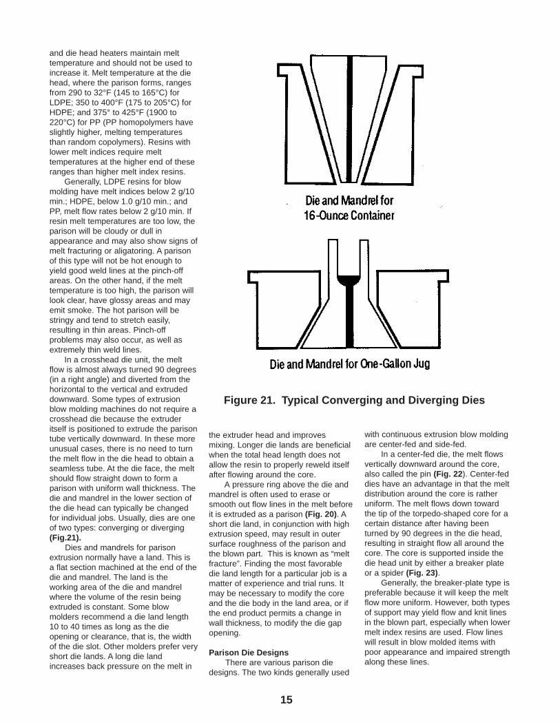
In a crosshead die unit, the meltflow is almost always turned 90 degrees(in a right angle) and diverted from thehorizontal to the vertical and extrudeddownward. Some types of extrusionblow molding machines do not require acrosshead die because the extruderitself is positioned to extrude the parisontube vertically downward. In these moreunusual cases, there is no need to turnthe melt flow in the die head to obtain aseamless tube. At the die face, the meltshould flow straight down to form aparison with uniform wall thickness. Thedie and mandrel in the lower section ofthe die head can typically be changedfor individual jobs. Usually, dies are oneof two types: converging or diverging(Fig.21).
Dies and mandrels for parisonextrusion normally have a land. This isa flat section machined at the end of thedie and mandrel. The land is theworking area of the die and mandrelwhere the volume of the resin beingextruded is constant. Some blowmolders recommend a die land length10 to 40 times as long as the dieopening or clearance, that is, the widthof the die slot. Other molders prefer veryshort die lands. A long die landincreases back pressure on the melt in
Figure 21. Typical Converging and Diverging Dies
the extruder head and improvesmixing. Longer die lands are beneficialwhen the total head length does notallow the resin to properly reweld itselfafter flowing around the core.
A pressure ring above the die andmandrel is often used to erase orsmooth out flow lines in the melt beforeit is extruded as a parison (Fig. 20). Ashort die land, in conjunction with highextrusion speed, may result in outersurface roughness of the parison andthe blown part. This is known as “meltfracture”. Finding the most favorabledie land length for a particular job is amatter of experience and trial runs. Itmay be necessary to modify the coreand the die body in the land area, or ifthe end product permits a change inwall thickness, to modify the die gapopening.
Parison Die DesignsThere are various parison die
designs. The two kinds generally used
with continuous extrusion blow moldingare center-fed and side-fed.
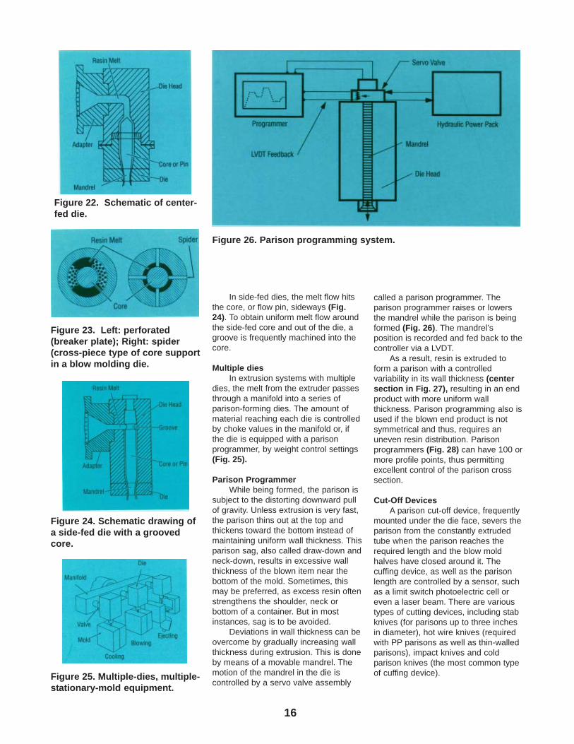
In a center-fed die, the melt flowsvertically downward around the core,also called the pin (Fig. 22). Center-feddies have an advantage in that the meltdistribution around the core is ratheruniform. The melt flows down towardthe tip of the torpedo-shaped core for acertain distance after having beenturned by 90 degrees in the die head,resulting in straight flow all around thecore. The core is supported inside thedie head unit by either a breaker plateor a spider (Fig. 23).
Generally, the breaker-plate type ispreferable because it will keep the meltflow more uniform. However, both typesof support may yield flow and knit linesin the blown part, especially when lowermelt index resins are used. Flow lineswill result in blow molded items withpoor appearance and impaired strengthalong these lines.
16
In side-fed dies, the melt flow hitsthe core, or flow pin, sideways (Fig.24). To obtain uniform melt flow aroundthe side-fed core and out of the die, agroove is frequently machined into thecore.
Multiple diesIn extrusion systems with multiple
dies, the melt from the extruder passesthrough a manifold into a series ofparison-forming dies. The amount ofmaterial reaching each die is controlledby choke values in the manifold or, ifthe die is equipped with a parisonprogrammer, by weight control settings(Fig. 25).
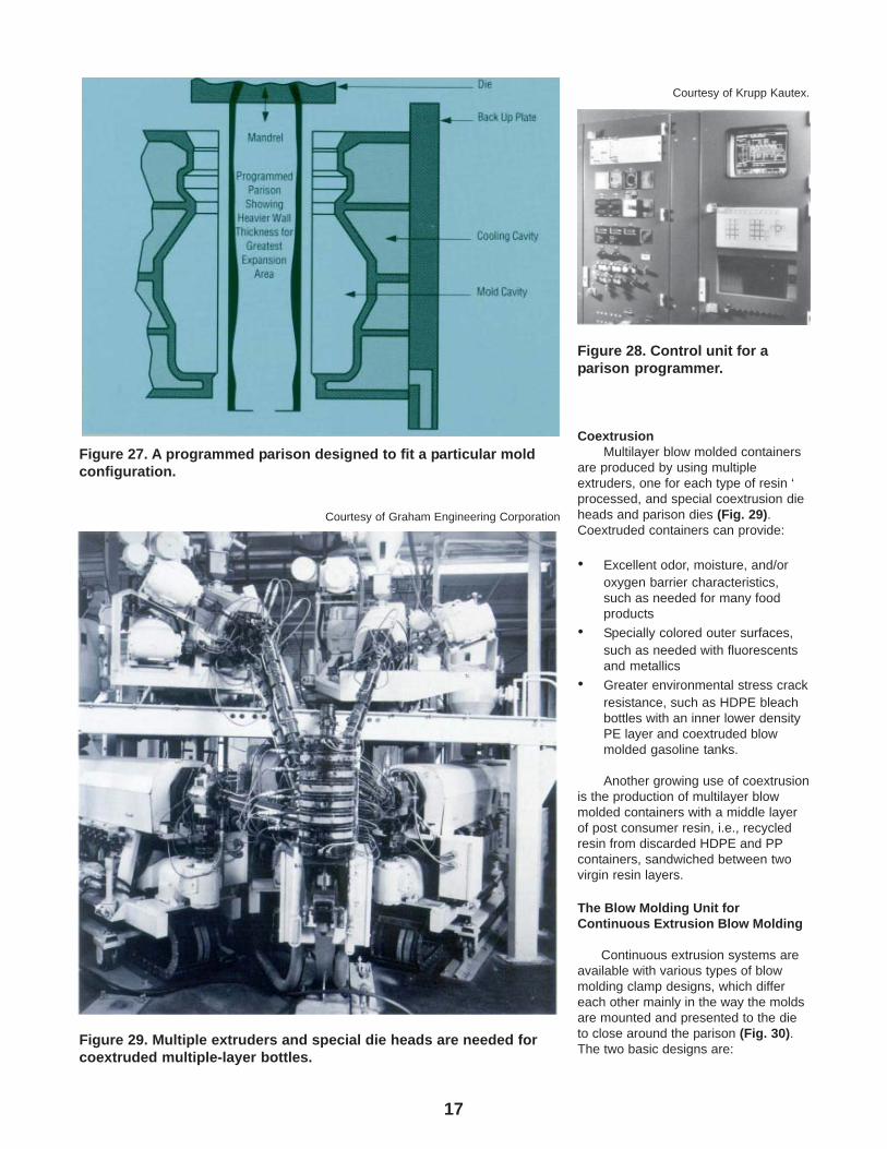
Parison ProgrammerWhile being formed, the parison is
subject to the distorting downward pullof gravity. Unless extrusion is very fast,the parison thins out at the top andthickens toward the bottom instead ofmaintaining uniform wall thickness. Thisparison sag, also called draw-down andneck-down, results in excessive wallthickness of the blown item near thebottom of the mold. Sometimes, thismay be preferred, as excess resin oftenstrengthens the shoulder, neck orbottom of a container. But in mostinstances, sag is to be avoided.
Deviations in wall thickness can beovercome by gradually increasing wallthickness during extrusion. This is doneby means of a movable mandrel. Themotion of the mandrel in the die iscontrolled by a servo valve assembly
called a parison programmer. Theparison programmer raises or lowersthe mandrel while the parison is beingformed (Fig. 26). The mandrel’sposition is recorded and fed back to thecontroller via a LVDT.
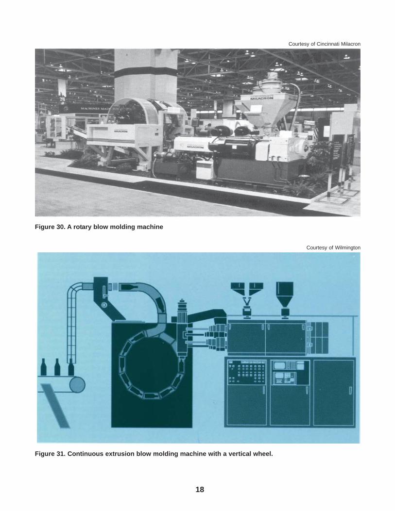
As a result, resin is extruded toform a parison with a controlledvariability in its wall thickness (centersection in Fig. 27), resulting in an endproduct with more uniform wallthickness. Parison programming also isused if the blown end product is notsymmetrical and thus, requires anuneven resin distribution. Parisonprogrammers (Fig. 28) can have 100 ormore profile points, thus permittingexcellent control of the parison crosssection.
Cut-Off DevicesA parison cut-off device, frequently
mounted under the die face, severs theparison from the constantly extrudedtube when the parison reaches therequired length and the blow moldhalves have closed around it. Thecuffing device, as well as the parisonlength are controlled by a sensor, suchas a limit switch photoelectric cell oreven a laser beam. There are varioustypes of cutting devices, including stabknives (for parisons up to three inchesin diameter), hot wire knives (requiredwith PP parisons as well as thin-walledparisons), impact knives and coldparison knives (the most common typeof cuffing device).
Figure 22. Schematic of center-fed die.
Figure 23. Left: perforated(breaker plate); Right: spider(cross-piece type of core supportin a blow molding die.
Figure 24. Schematic drawing ofa side-fed die with a groovedcore.
Figure 25. Multiple-dies, multiple-stationary-mold equipment.
Figure 26. Parison programming system.
17
CoextrusionMultilayer blow molded containers
are produced by using multipleextruders, one for each type of resin ‘processed, and special coextrusion dieheads and parison dies (Fig. 29).Coextruded containers can provide:
• Excellent odor, moisture, and/oroxygen barrier characteristics,such as needed for many foodproducts
• Specially colored outer surfaces,such as needed with fluorescentsand metallics
• Greater environmental stress crackresistance, such as HDPE bleachbottles with an inner lower densityPE layer and coextruded blowmolded gasoline tanks.
Another growing use of coextrusionis the production of multilayer blowmolded containers with a middle layerof post consumer resin, i.e., recycledresin from discarded HDPE and PPcontainers, sandwiched between twovirgin resin layers.
The Blow Molding Unit forContinuous Extrusion Blow Molding
Continuous extrusion systems areavailable with various types of blowmolding clamp designs, which differeach other mainly in the way the moldsare mounted and presented to the dieto close around the parison (Fig. 30).The two basic designs are:
Figure 27. A programmed parison designed to fit a particular moldconfiguration.
Figure 28. Control unit for aparison programmer.
Courtesy of Krupp Kautex.
Figure 29. Multiple extruders and special die heads are needed forcoextruded multiple-layer bottles.
Courtesy of Graham Engineering Corporation
18
Figure 30. A rotary blow molding machine
Courtesy of Cincinnati Milacron
Figure 31. Continuous extrusion blow molding machine with a vertical wheel.
Courtesy of Wilmington
19
• molds that move on a rotatingwheel or table
• molds that are shuttled to theparison die.
The mold halves, mounted onplatens, are held together during theblowing step by presses that areactuated either by a mechanical togglemechanism or hydraulic cylinders. Lowclamping pressures, compared withthose used with injection moldingmachines, are used with extrusion blowmolding. On some blow moldingpresses, mold closing is carried out intwo steps, first at high speed, with lowerpressure and then slower to full close,with higher pressure. This sequenceprotects the mold from damage byanything that might have fallen betweenthe halves. It also enhances andincreases operator safety.
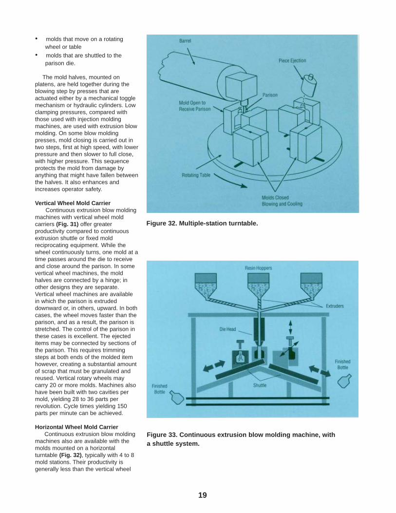
Vertical Wheel Mold CarrierContinuous extrusion blow molding
machines with vertical wheel moldcarriers (Fig. 31) offer greaterproductivity compared to continuousextrusion shuttle or fixed moldreciprocating equipment. While thewheel continuously turns, one mold at atime passes around the die to receiveand close around the parison. In somevertical wheel machines, the moldhalves are connected by a hinge; inother designs they are separate.Vertical wheel machines are availablein which the parison is extrudeddownward or, in others, upward. In bothcases, the wheel moves faster than theparison, and as a result, the parison isstretched. The control of the parison inthese cases is excellent. The ejecteditems may be connected by sections ofthe parison. This requires trimmingsteps at both ends of the molded itemhowever, creating a substantial amountof scrap that must be granulated andreused. Vertical rotary wheels maycarry 20 or more molds. Machines alsohave been built with two cavities permold, yielding 28 to 36 parts perrevolution. Cycle times yielding 150parts per minute can be achieved.
Horizontal Wheel Mold CarrierContinuous extrusion blow molding
machines also are available with themolds mounted on a horizontalturntable (Fig. 32), typically with 4 to 8mold stations. Their productivity isgenerally less than the vertical wheel
Figure 32. Multiple-station turntable.
Figure 33. Continuous extrusion blow molding machine, witha shuttle system.
20
machines which carry more moldstations. The operation of thecontinuously moving turntable isessentially the same as that of therotary wheel. Indexing turntables andwheels also are available.
Horizontal turntables may produceless scrap than vertical wheels becausethe parison is cut from the die face by acut-off knife. Consequently, the blownpieces are not connected to each otherand the “tail” flash can be kept short.Automatic ejection can also be easierthan from a mold on a rotary wheel,without the need for knockout pins.The advantages of higher output areobvious. However, the higher outputmachines are more expensive initially,as are dual cavity molds.
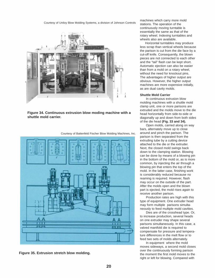
Shuttle Mold CarrierIn continuous extrusion blow
molding machines with a shuttle moldclamp unit, one or more parisons areextruded and the molds move to the diehead horizontally from side-to-side ordiagonally up and down from both sidesof the die head (Fig. 33 and 34).
Open molds, carried along on waybars, alternately move up to closearound and pinch the parison. Theparison is then separated from theextruding tube by a cutting deviceattached to the die or the extruder.Next, the closed mold swings backdown to the clamping station. Blowingcan be done by means of a blowing pinin the bottom of the mold or, as is morecommon, by injecting the air through ablowing pin that enters the top of themold. In the latter case, finishing workis considerably reduced because noreaming is required. However, flashmay occur on the outside of the part.After the molds open and the blownpart is ejected, the mold rises again toreceive another parison.
Production rates are high with thistype of equipment. One extruder headmay form multiple parisons simulta-neously to feed multiple mold cavities.
Dies are of the crosshead type. Or,to increase production, several headson one extruder may shape severalparisons simultaneously. In this case, avalved manifold die is required tocompensate for pressure and tempera-ture differences in the melt flow or tofeed two sets of molds alternately.
In equipment where the moldmoves sideways, a second mold closesover the continuously forming parisonthe moment the first mold moves to theright or left for blowing. Compared with
Figure 34. Continuous extrusion blow moding machine with ashuttle mold carrier.
Courtesy of Uniloy Blow Molding Systems, a division of Johnson Controls
Figure 35. Extrusion stretch blow molding.
Courtesy of Battenfeld Fischer Blow Molding Machines, Inc.
21
the swinging-mold procedure, thesliding-mold method either may permithigher production rates or allow for alonger cooling period, which may beadvantageous to obtain certain endproduct properties.
Hydraulic systems generally areused for clamping and moving themolds, the platens on which they aremounted and other heavy parts of themolding equipment, such as rams usedin accumulator heads.
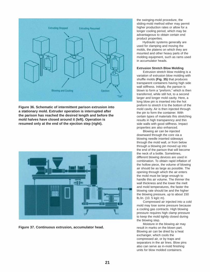
Extrusion Stretch Blow MoldingExtrusion stretch blow molding is a
variation of extrusion blow molding withshuffle molds (Fig. 35) that producestransparent containers having high sidewall stiffness. Initially, the parison isblown to form a “preform,” which is thentransferred, while still hot, to a secondlarger and longer mold cavity. Here, along blow pin is inserted into the hotpreform to stretch it to the bottom of themold cavity. Air is then injected throughthe pin to form the container. Withcertain types of materials this stretchingresults in high transparency and thinside walls with good stiffness. Impactproperties are also enhanced.
Blowing air can be injecteddownward through the core via ablowing needle inserted sidewaysthrough the mold wall, or from belowthrough a blowing pin moved up intothe end of the parison that will becomethe neck of a bottle. Sometimes,different blowing devices are used incombination. To obtain rapid inflation ofthe hollow piece, the volume of blowingair should be as large as possible. Theopening through which the air entersthe mold must be large enough tohandle this air volume. The thinner thewall thickness and the lower the meltand mold temperatures, the faster theblowing rate should be and the higherthe blowing pressure, up to about 150lb./in. (10. 5 kg/c m).
Compressed air injected into a coldmold may lose some pressure becausea cooling gas contracts. High blowingpressure requires high clamp pressureto keep the mold tightly closed duringthe blowing step.
Moisture in the blowing air mayresult in marks on the blown part.Blowing air can be dried by a heatexchanger, which cools thecompressed air, or by traps andseparators in the air lines. Blow pinsalso can serve as in-mold finishingunits for blow molded containers.
Figure 36. Schematic of intermittent parison extrusion intoa stationary mold. Extruder operation is interrupted afterthe parison has reached the desired length and before themold halves have closed around it (left). Operation isresumed only at the end of the ejection step (right).
Figure 37. Continuous extrusion, accumulator head.
22
Various types of blow pins for in-moldneck finishing are available (see“In-mold Trimming” pg. 27).
Intermittent Blow Molding SystemsThere are three basic types of
intermittent blow molding systems:
1. Intermittent extrusion blow molding2. Reciprocating Extrusion Blow
Molding3. Injection Blow Molding
Intermittent Extrusion Blow MoldingIntermittent extruder operation with
a stationary mold is the simplestpossible blow molding arrangement.The stationary mold is located directlybelow the crosshead die that extrudesthe parison between the mold halves.There may be several molds if morethan one parison is extrudedsimultaneously. Air is blown into themold usually through the core in the dieor through a mandrel (blow stick)inserted from below.
In intermittent extrusion blowmolding (Fig. 36), the extruder screwoperation is halted when the parisonhas reached the desired length. Themold halves close around the parison,the finished part is blown, cooled andejected. The next parison is then isextruded. Because the extruderoperation is stopped for the greater partof every blow molding cycle, thisprocess is less efficient than those inwhich the extruder operatescontinuously and the cycle times of thevarious moldings overlap.
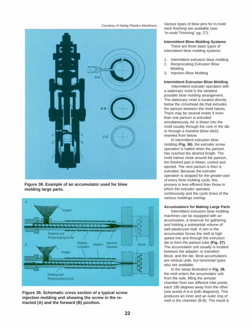
Accumulators for Making Large PartsIntermittent extrusion blow molding
machines can be equipped with anaccumulator, a reservoir for gatheringand holding a substantial volume ofwell plasticized melt. A ram in theaccumulator forces the melt at highspeed into and through the extrusiondie to form the parison tube (Fig. 37).The accumulator unit usually is locatedbetween the adapter, or transitionblock, and the die. Most accumulatorsare vertical units, but horizontal typesalso are available.
In the setup illustrated in Fig. 38,the melt enters the accumulator unitfrom the side, filling the annularchamber from two different inlet points,each 180 degrees away from the other(see points A-A in both diagrams). Thisproduces an inner and an outer ring ofmelt in the chamber (B-B). The result is
Figure 39. Schematic cross section of a typical screwinjection molding unit showing the screw in the re-tracted (A) and the forward (B) position.
Figure 38. Example of an accumulator used for blowmolding large parts.
Courtesy of Hartig Plastics Machinery
23
that the seam formed by the material inthe inner ring is directly opposite theseam formed by the material in theouter ring. When the material from theinner and outer rings comes togetherfurther downstream in the flow process(C-C), there is no weld or seam line thatgoes all the way through the parison atany one point, thus ensuring wallintegrity.
An accumulator offers theseadvantages:
1 . It holds ready a large volume ofmelt for large items requiring verylong molding (cooling) cycles, up toseveral minutes in length.
2. It permits high production rates.3. It enables fast extrusion of large
parisons (short parison formationtime) and consequently, shortsuspension time for the parison andthus, very little sag.
4. It results in good parison walluniformity.
5. It enables uniform shot sizes and,thus, a minimum of waste.
6. It decreases idle mold time to aminimum.
An accumulator may hold up to300 lb. (135 kg) of resin. Oneaccumulator may cover several moldsor each mold may have its ownaccumulator. In the latter case, whilethe extruder operates continuously, themolds may be fed alternately; whilesome will receive their parisons, othersare in the cooling stage, etc.
In accumulator type systems, backpressure can be increased by a needlevalve in the hydraulic system. Thisvalve (restriction) controls the hydraulicoil flow from the accumulator so thatmore pressure is required from thecompaction of the resin to force the ramback and the oil from the cylinderreservoir into the tank reservoir. Thesame principle holds true forreciprocating screw machines. (Seenext section.)
Manifold die heads, generallywithout sequence valves, are also usedin machines equipped with anaccumulator. In such equipment,extrusion through all the dies takesplace simultaneously, so there is novalve-controlled alternate flow required.For best results in die heads that
produce intermittent resin flow, the areain the heads should be great enough toproduce a complete parison for the next“shot.” This permits the resin to becomeheat stabilized and produce a moreuniform parison.
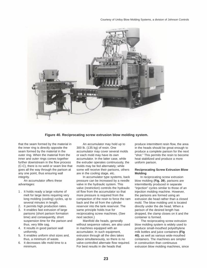
Reciprocating Screw Extrusion BlowMolding
In reciprocating screw extrusionblow molding (Fig. 39), parisons areintermittently produced in separate“injection” cycles similar to those of aninjection molding machine. However,the parisons are formed using anextrusion die head rather than a closedmold. The blow molding unit is locateddirectly under the die head. When aparison of the desired length hasdropped, the clamp closes on it and thecontainer is formed.
The reciprocating screw extrusionblow molding system is widely used toproduce small-mouthed polyethylenemilk bottles and juice containers (Fig40), as well as various wide-mouthedcontainers. The machines are simplerin construction than continuousextrusion blow molding machines, since
Figure 40. Reciprocating screw extrusion blow molding system.
Courtesy of Uniloy Blow Molding Systems, a division of Johnson Controls
24
the clamp unit is stationary and doesnot require any mold shuttlingmechanism. Further, tooling costs arelower (only one set is needed), andhandleware and off -set neckcontainers can be easily formed. Thefast parison formation that occurs in the“injection” cycle permits resins withhigher melt indices to be used sincemelt strength requirements are lessstringent than those needed forcontinuous extrusion blow molding.
In reciprocating screw extrusionblow molding, polyolefin pellets are firstfed into the hopper of the plasticatingunit (see Fig. 39). The screw, in anelectrically heated barrel, rotates andretracts as the resin is pushed forward.As the resin pellets move forward in thescrew channels, they melt by thecombined action of screw and barrelshear forces and heaters located alongthe barrel. Gradually a melt forms; it ismixed, becomes more fluid, andreaches the viscosity required forinjection into the die head. While thepellets are melted in the barrel, thegradually decreasing depth of thescrew channels squeezes the air out ofthe softened mass; the air flows backalong the clearance between the screwflights and the barrel and out throughthe hopper. The melt then flows overthe screw tip into a chamber at the frontof the barrel. The build-up of the meltforces the screw backwards.
When the desired amount of melt(shot size) is reached in the chamber,the screw pushes forward and forcesthe melt, at a high speed, through the
nozzle and out through the die head.The screw then begins to turn againand retracts within the barrel to preparethe next shot. The speed of the screw isin balance with the parison size and thecontainer blow time. Reciprocatingscrew extrusion blow molding machinesare available with shot capacities up to2,500 grams (HDPE) and throughputrates up to 750 lbs./hr.
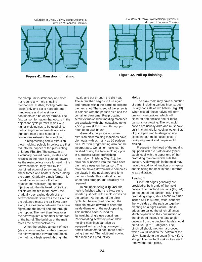
Generally, reciprocating screwextrusion blow molding machines havedie heads with as many as 10 parisondies. Parison programming also can beincorporated. Container necks can befinished during the blow molding cyclein a process called prefinishing.In ram down finishing (Fig. 41), theblow pin is inserted into the mold afterthe mold closes on the parison. Theblow pin moves downward to compressthe plastic in the neck area and formthe neck finish. This method is usedwhen neck strength and reliability arerequired.
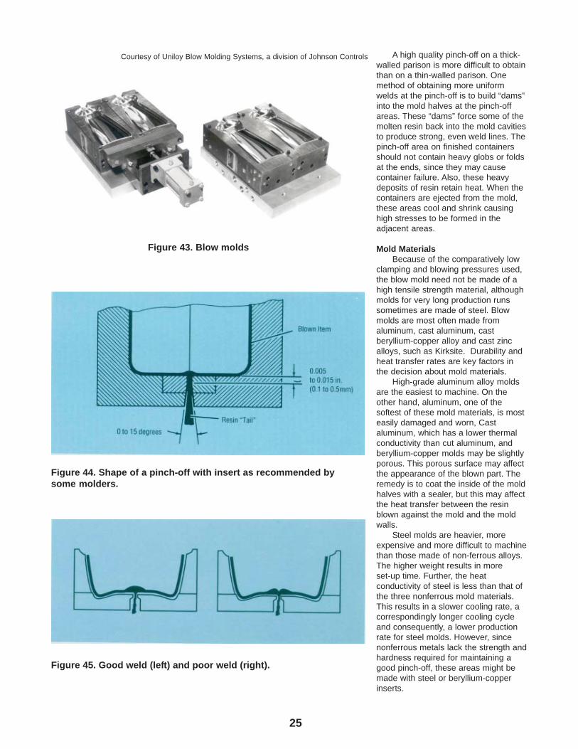
In pull-up finishing (Fig. 42), theneck is finished when the blow pin isinserted just before the mold closes onthe parison. At the end of the blowcycle, but before mold opening, theblow pin moves upward to shear theinside diameter of the neck opening.This method often is used forlightweight, single use containers.Reciprocating screw extrusion blowmolding machines can also beequipped with a cooling conveyor topermit containers to cool more beforebeing trimmed. The additional coolingstep increases productivity.
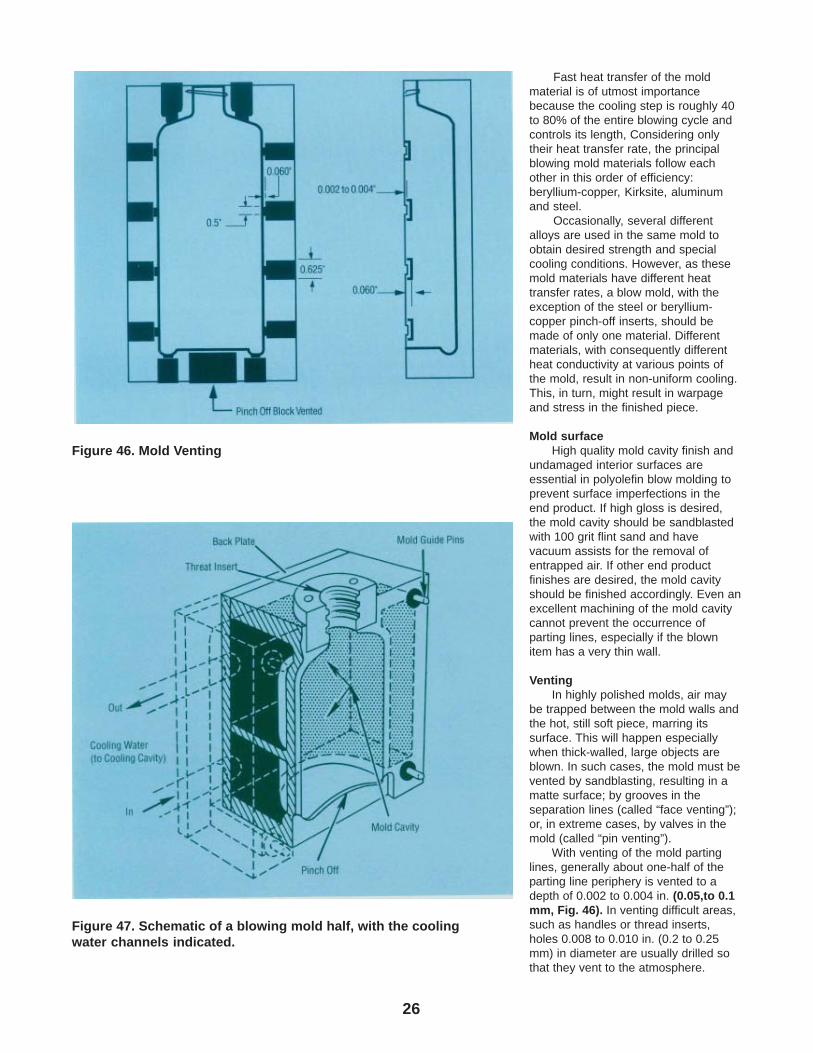
MoldsThe blow mold may have a number
of parts, including various inserts, but itusually consists of two halves (Fig. 43).When closed, these halves will formone or more cavities, which willpinch-off and enclose one or moreparisons for blowing. The two moldhalves are usually alike and must havebuilt-in channels for cooling water. Setsof guide pins and bushings or sideplates in both mold halves ensurecavity alignment and proper moldclosing.
Frequently, the head of the mold isequipped with a cut-off device (shearsteel) level with the upper end of theprotruding mandrel which cuts theparison. A blowing pin in the mold mayhave the additional function of shapingand finishing the neck interior, referredto as calibrating.
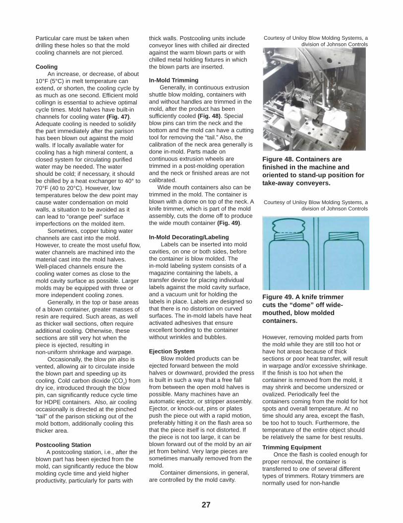
Pinch-offPinch-off edges generally are
provided at both ends of the moldhalves. The pinch-off sections (Fig. 44)do not cut off the parison “tail.” Theirprotruding edges, about 0.005 to 0.015inches (0.1 to 0.5mm) wide, squeezethe two sides of the parison together,creating an airtight closure. Theseedges are called the pinch-off lands.Much depends on the construction ofthe pinch-off insert. The total angleoutward from the pinch-off lands shouldbe acute, up to 15 degrees. Thepinch-off should not form a groove,which would weaken the bottom of theblown item along the seam (Fig. 45). Astraight line pinch-off makes it easier toremove the “tail” piece.
Figure 41. Ram down finishing.
Courtesy of Uniloy Blow Molding Systems, adivision of Johnson Controls
Figure 42. Pull-up finishing.
Courtesy of Uniloy Blow Molding Systems, adivision of Johnson Controls
25
A high quality pinch-off on a thick-walled parison is more difficult to obtainthan on a thin-walled parison. Onemethod of obtaining more uniformwelds at the pinch-off is to build “dams”into the mold halves at the pinch-offareas. These “dams” force some of themolten resin back into the mold cavitiesto produce strong, even weld lines. Thepinch-off area on finished containersshould not contain heavy globs or foldsat the ends, since they may causecontainer failure. Also, these heavydeposits of resin retain heat. When thecontainers are ejected from the mold,these areas cool and shrink causinghigh stresses to be formed in theadjacent areas.
Mold MaterialsBecause of the comparatively low
clamping and blowing pressures used,the blow mold need not be made of ahigh tensile strength material, althoughmolds for very long production runssometimes are made of steel. Blowmolds are most often made fromaluminum, cast aluminum, castberyllium-copper alloy and cast zincalloys, such as Kirksite. Durability andheat transfer rates are key factors inthe decision about mold materials.
High-grade aluminum alloy moldsare the easiest to machine. On theother hand, aluminum, one of thesoftest of these mold materials, is mosteasily damaged and worn, Castaluminum, which has a lower thermalconductivity than cut aluminum, andberyllium-copper molds may be slightlyporous. This porous surface may affectthe appearance of the blown part. Theremedy is to coat the inside of the moldhalves with a sealer, but this may affectthe heat transfer between the resinblown against the mold and the moldwalls.
Steel molds are heavier, moreexpensive and more difficult to machinethan those made of non-ferrous alloys.The higher weight results in moreset-up time. Further, the heatconductivity of steel is less than that ofthe three nonferrous mold materials.This results in a slower cooling rate, acorrespondingly longer cooling cycleand consequently, a lower productionrate for steel molds. However, sincenonferrous metals lack the strength andhardness required for maintaining agood pinch-off, these areas might bemade with steel or beryllium-copperinserts.
Figure 44. Shape of a pinch-off with insert as recommended bysome molders.
Figure 45. Good weld (left) and poor weld (right).
Figure 43. Blow molds
Courtesy of Uniloy Blow Molding Systems, a division of Johnson Controls
26
Fast heat transfer of the moldmaterial is of utmost importancebecause the cooling step is roughly 40to 80% of the entire blowing cycle andcontrols its length, Considering onlytheir heat transfer rate, the principalblowing mold materials follow eachother in this order of efficiency:beryllium-copper, Kirksite, aluminumand steel.
Occasionally, several differentalloys are used in the same mold toobtain desired strength and specialcooling conditions. However, as thesemold materials have different heattransfer rates, a blow mold, with theexception of the steel or beryllium-copper pinch-off inserts, should bemade of only one material. Differentmaterials, with consequently differentheat conductivity at various points ofthe mold, result in non-uniform cooling.This, in turn, might result in warpageand stress in the finished piece.
Mold surfaceHigh quality mold cavity finish and
undamaged interior surfaces areessential in polyolefin blow molding toprevent surface imperfections in theend product. If high gloss is desired,the mold cavity should be sandblastedwith 100 grit flint sand and havevacuum assists for the removal ofentrapped air. If other end productfinishes are desired, the mold cavityshould be finished accordingly. Even anexcellent machining of the mold cavitycannot prevent the occurrence ofparting lines, especially if the blownitem has a very thin wall.
VentingIn highly polished molds, air may
be trapped between the mold walls andthe hot, still soft piece, marring itssurface. This will happen especiallywhen thick-walled, large objects areblown. In such cases, the mold must bevented by sandblasting, resulting in amatte surface; by grooves in theseparation lines (called “face venting”);or, in extreme cases, by valves in themold (called “pin venting”).
With venting of the mold partinglines, generally about one-half of theparting line periphery is vented to adepth of 0.002 to 0.004 in. (0.05,to 0.1mm, Fig. 46). In venting difficult areas,such as handles or thread inserts,holes 0.008 to 0.010 in. (0.2 to 0.25mm) in diameter are usually drilled sothat they vent to the atmosphere.
Figure 46. Mold Venting
Figure 47. Schematic of a blowing mold half, with the coolingwater channels indicated.
27
Particular care must be taken whendrilling these holes so that the moldcooling channels are not pierced.
CoolingAn increase, or decrease, of about
10°F (5°C) in melt temperature canextend, or shorten, the cooling cycle byas much as one second. Efficient moldcollingn is essential to achieve optimalcycle times. Mold halves have built-inchannels for cooling water (Fig. 47).Adequate cooling is needed to solidifythe part immediately after the parisonhas been blown out against the moldwalls. If locally available water forcooling has a high mineral content, aclosed system for circulating purifiedwater may be needed. The watershould be cold; if necessary, it shouldbe chilled by a heat exchanger to 40° to70°F (40 to 20°C). However, lowtemperatures below the dew point maycause water condensation on moldwalls, a situation to be avoided as itcan lead to “orange peel” surfaceimperfections on the molded item.
Sometimes, copper tubing waterchannels are cast into the mold.However, to create the most useful flow,water channels are machined into thematerial cast into the mold halves.Well-placed channels ensure thecooling water comes as close to themold cavity surface as possible. Largermolds may be equipped with three ormore independent cooling zones.
Generally, in the top or base areasof a blown container, greater masses ofresin are required. Such areas, as wellas thicker wall sections, often requireadditional cooling. Otherwise, thesesections are still very hot when thepiece is ejected, resulting innon-uniform shrinkage and warpage.
Occasionally, the blow pin also isvented, allowing air to circulate insidethe blown part and speeding up itscooling. Cold carbon dioxide (CO
2) from
dry ice, introduced through the blowpin, can significantly reduce cycle timefor HDPE containers. Also, air coolingoccasionally is directed at the pinched“tail” of the parison sticking out of themold bottom, additionally cooling thisthicker area.
Postcooling StationA postcooling station, i.e., after the
blown part has been ejected from themold, can significantly reduce the blowmolding cycle time and yield higherproductivity, particularly for parts with
thick walls. Postcooling units includeconveyor lines with chilled air directedagainst the warm blown parts or withchilled metal holding fixtures in whichthe blown parts are inserted.
In-Mold TrimmingGenerally, in continuous extrusion
shuttle blow molding, containers withand without handles are trimmed in themold, after the product has beensufficiently cooled (Fig. 48). Specialblow pins can trim the neck and thebottom and the mold can have a cuttingtool for removing the “tail.” Also, thecalibration of the neck area generally isdone in-mold. Parts made oncontinuous extrusion wheels aretrimmed in a post-molding operationand the neck or finished areas are notcalibrated.
Wide mouth containers also can betrimmed in the mold. The container isblown with a dome on top of the neck. Aknife trimmer, which is part of the moldassembly, cuts the dome off to producethe wide mouth container (Fig. 49).
In-Mold Decorating/LabelingLabels can be inserted into mold
cavities, on one or both sides, beforethe container is blow molded. Thein-mold labeling system consists of amagazine containing the labels, atransfer device for placing individuallabels against the mold cavity surface,and a vacuum unit for holding thelabels in place. Labels are designed sothat there is no distortion on curvedsurfaces. The in-mold labels have heatactivated adhesives that ensureexcellent bonding to the containerwithout wrinkles and bubbles.
Ejection SystemBlow molded products can be
ejected forward between the moldhalves or downward, provided the pressis built in such a way that a free fallfrom between the open mold halves ispossible. Many machines have anautomatic ejector, or stripper assembly.Ejector, or knock-out, pins or platespush the piece out with a rapid motion,preferably hitting it on the flash area sothat the piece itself is not distorted. Ifthe piece is not too large, it can beblown forward out of the mold by an airjet from behind. Very large pieces aresometimes manually removed from themold.
Container dimensions, in general,are controlled by the mold cavity.
However, removing molded parts fromthe mold while they are still too hot orhave hot areas because of thicksections or poor heat transfer, will resultin warpage and/or excessive shrinkage.If the finish is too hot when thecontainer is removed from the mold, itmay shrink and become undersized orovalized. Periodically feel thecontainers coming from the mold for hotspots and overall temperature. At notime should any area, except the flash,be too hot to touch. Furthermore, thetemperature of the entire object shouldbe relatively the same for best results.
Trimming EquipmentOnce the flash is cooled enough for
proper removal, the container istransferred to one of several differenttypes of trimmers. Rotary trimmers arenormally used for non-handle
Figure 48. Containers arefinished in the machine andoriented to stand-up position fortake-away conveyers.
Courtesy of Uniloy Blow Molding Systems, adivision of Johnson Controls
Figure 49. A knife trimmercuts the “dome” off wide-mouthed, blow moldedcontainers.
Courtesy of Uniloy Blow Molding Systems, adivision of Johnson Controls
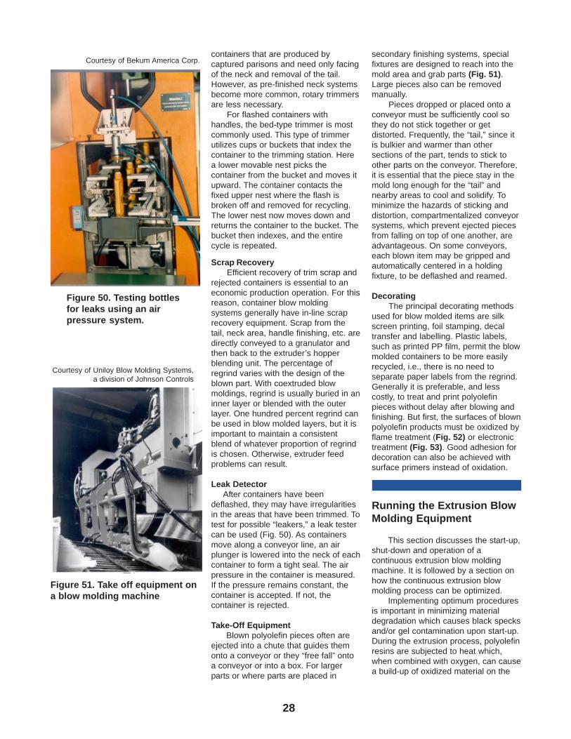
28
containers that are produced bycaptured parisons and need only facingof the neck and removal of the tail.However, as pre-finished neck systemsbecome more common, rotary trimmersare less necessary.
For flashed containers withhandles, the bed-type trimmer is mostcommonly used. This type of trimmerutilizes cups or buckets that index thecontainer to the trimming station. Herea lower movable nest picks thecontainer from the bucket and moves itupward. The container contacts thefixed upper nest where the flash isbroken off and removed for recycling.The lower nest now moves down andreturns the container to the bucket. Thebucket then indexes, and the entirecycle is repeated.
Scrap RecoveryEfficient recovery of trim scrap and
rejected containers is essential to aneconomic production operation. For thisreason, container blow moldingsystems generally have in-line scraprecovery equipment. Scrap from thetail, neck area, handle finishing, etc. aredirectly conveyed to a granulator andthen back to the extruder’s hopperblending unit. The percentage ofregrind varies with the design of theblown part. With coextruded blowmoldings, regrind is usually buried in aninner layer or blended with the outerlayer. One hundred percent regrind canbe used in blow molded layers, but it isimportant to maintain a consistentblend of whatever proportion of regrindis chosen. Otherwise, extruder feedproblems can result.
Leak DetectorAfter containers have been
deflashed, they may have irregularitiesin the areas that have been trimmed. Totest for possible “leakers,” a leak testercan be used (Fig. 50). As containersmove along a conveyor line, an airplunger is lowered into the neck of eachcontainer to form a tight seal. The airpressure in the container is measured.If the pressure remains constant, thecontainer is accepted. If not, thecontainer is rejected.
Take-Off EquipmentBlown polyolefin pieces often are
ejected into a chute that guides themonto a conveyor or they “free fall” ontoa conveyor or into a box. For largerparts or where parts are placed in
secondary finishing systems, specialfixtures are designed to reach into themold area and grab parts (Fig. 51).Large pieces also can be removedmanually.
Pieces dropped or placed onto aconveyor must be sufficiently cool sothey do not stick together or getdistorted. Frequently, the “tail,” since itis bulkier and warmer than othersections of the part, tends to stick toother parts on the conveyor. Therefore,it is essential that the piece stay in themold long enough for the “tail” andnearby areas to cool and solidify. Tominimize the hazards of sticking anddistortion, compartmentalized conveyorsystems, which prevent ejected piecesfrom falling on top of one another, areadvantageous. On some conveyors,each blown item may be gripped andautomatically centered in a holdingfixture, to be deflashed and reamed.
DecoratingThe principal decorating methods
used for blow molded items are silkscreen printing, foil stamping, decaltransfer and labelling. Plastic labels,such as printed PP film, permit the blowmolded containers to be more easilyrecycled, i.e., there is no need toseparate paper labels from the regrind.Generally it is preferable, and lesscostly, to treat and print polyolefinpieces without delay after blowing andfinishing. But first, the surfaces of blownpolyolefin products must be oxidized byflame treatment (Fig. 52) or electronictreatment (Fig. 53). Good adhesion fordecoration can also be achieved withsurface primers instead of oxidation.
Running the Extrusion BlowMolding Equipment
This section discusses the start-up,shut-down and operation of acontinuous extrusion blow moldingmachine. It is followed by a section onhow the continuous extrusion blowmolding process can be optimized.
Implementing optimum proceduresis important in minimizing materialdegradation which causes black specksand/or gel contamination upon start-up.During the extrusion process, polyolefinresins are subjected to heat which,when combined with oxygen, can causea build-up of oxidized material on the
Figure 50. Testing bottlesfor leaks using an airpressure system.
Courtesy of Bekum America Corp.
Figure 51. Take off equipment ona blow molding machine
Courtesy of Uniloy Blow Molding Systems,a division of Johnson Controls
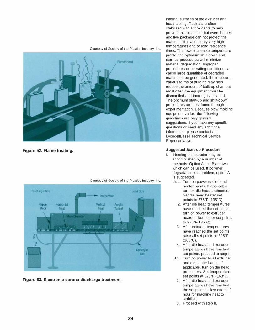
29
internal surfaces of the extruder and head tooling. Resins are often stabilized with antioxidants to help prevent this oxidation, but even the best additive package can not protect the material if it is abused by very high temperatures and/or long residence times. The lowest useable temperature profile and optimum shut-down and start-up procedures will minimize material degradation. Improper procedures or operating conditions can cause large quantities of degraded material to be generated. If this occurs, various forms of purging may help reduce the amount of built-up char, but most often the equipment must be dismantled and thoroughly cleaned. The optimum start-up and shut-down procedures are best found through experimentation. Because blow molding equipment varies, the following guidelines are only general suggestions. If you have any specific questions or need any additional information, please contact an LyondellBasell Technical Service Representative.
Suggested Start-up ProcedureI. Heating the extruder may be
accomplished by a number ofmethods. Option A and B are twowhich can be used. If polymerdegradation is a problem, option Ais suggested.A. 1. Turn on power to die head
heater bands. If applicable,turn on die head preheaters.Set die head heater setpoints to 275°F (135°C).
2. After die head temperatureshave reached the set points,turn on power to extruderheaters. Set heater set pointsto 275°F(135°C).
3. After extruder temperatureshave reached the set points,raise all set points to 325°F(163°C).
4. After die head and extrudertemperatures have reachedset points, proceed to step II.
B.1. Turn on power to all extruderand die heater bands. Ifapplicable, turn on die headpreheaters. Set temperatureset points at 325°F (163°C).
2. After die head and extrudertemperatures have reachedthe set points, allow one halfhour for machine heat tostabilize.
3. Proceed with step II.
Figure 52. Flame treating.
Courtesy of Society of the Plastics Industry, Inc.
Courtesy of Society of the Plastics Industry, Inc.
Figure 53. Electronic corona-discharge treatment.
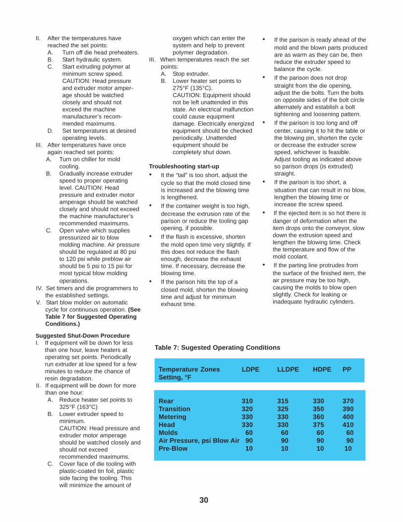
30
II. After the temperatures havereached the set points:A. Turn off die head preheaters.B. Start hydraulic system.C. Start extruding polymer at
minimum screw speed.CAUTION: Head pressureand extruder motor amper-age should be watchedclosely and should notexceed the machinemanufacturer’s recom-mended maximums.
D. Set temperatures at desiredoperating levels.
III. After temperatures have onceagain reached set points:A. Turn on chiller for mold
cooling.B. Gradually increase extruder
speed to proper operatinglevel. CAUTION: Headpressure and extruder motoramperage should be watchedclosely and should not exceedthe machine manufacturer’srecommended maximums.
C. Open valve which suppliespressurized air to blowmolding machine. Air pressureshould be regulated at 80 psito 120 psi while preblow airshould be 5 psi to 15 psi formost typical blow moldingoperations.
IV. Set timers and die programmers tothe established settings.
V. Start blow molder on automaticcycle for continuous operation. (SeeTable 7 for Suggested OperatingConditions.)
Suggested Shut-Down ProcedureI. If equipment will be down for less
than one hour, leave heaters atoperating set points. Periodicallyrun extruder at low speed for a fewminutes to reduce the chance ofresin degradation.
II. If equipment will be down for morethan one hour:A. Reduce heater set points to
325°F (163°C)B. Lower extruder speed to
minimum.CAUTION: Head pressure andextruder motor amperageshould be watched closely andshould not exceedrecommended maximums.
C. Cover face of die tooling withplastic-coated tin foil, plasticside facing the tooling. Thiswill minimize the amount of
oxygen which can enter thesystem and help to preventpolymer degradation.
III. When temperatures reach the setpoints:A. Stop extruder.B. Lower heater set points to
275°F (135°C).CAUTION: Equipment shouldnot be left unattended in thisstate. An electrical malfunctioncould cause equipmentdamage. Electrically energizedequipment should be checkedperiodically. Unattendedequipment should becompletely shut down.
Troubleshooting start-up
• It the “tail” is too short, adjust thecycle so that the mold closed timeis increased and the blowing timeis lengthened.
• If the container weight is too high,decrease the extrusion rate of theparison or reduce the tooling gapopening, if possible.
• If the flash is excessive, shortenthe mold open time very slightly. Ifthis does not reduce the flashenough, decrease the exhausttime. If necessary, decrease theblowing time.
• If the parison hits the top of aclosed mold, shorten the blowingtime and adjust for minimumexhaust time.
• If the parison is ready ahead of themold and the blown parts producedare as warm as they can be, thenreduce the extruder speed tobalance the cycle.
• If the parison does not dropstraight from the die opening,adjust the die bolts. Turn the boltson opposite sides of the bolt circlealternately and establish a bolttightening and loosening pattern.
• If the parison is too long and offcenter, causing it to hit the table orthe blowing pin, shorten the cycleor decrease the extruder screwspeed, whichever is feasible.Adjust tooling as indicated aboveso parison drops (is extruded)straight.
• If the parison is too short, asituation that can result in no blow,lengthen the blowing time orincrease the screw speed.
• If the ejected item is so hot there isdanger of deformation when theitem drops onto the conveyor, slowdown the extrusion speed andlengthen the blowing time. Checkthe temperature and flow of themold coolant.
• If the parting line protrudes fromthe surface of the finished item, theair pressure may be too high,causing the molds to blow openslightly. Check for leaking orinadequate hydraulic cylinders.
Temperature Zones LDPE LLDPE HDPE PPSetting, °F
Rear 310 315 330 370Transition 320 325 350 390Metering 330 330 360 400Head 330 330 375 410Molds 60 60 60 60Air Pressure, psi Blow Air 90 90 90 90Pre-Blow 10 10 10 10
Table 7: Sugested Operating Conditions
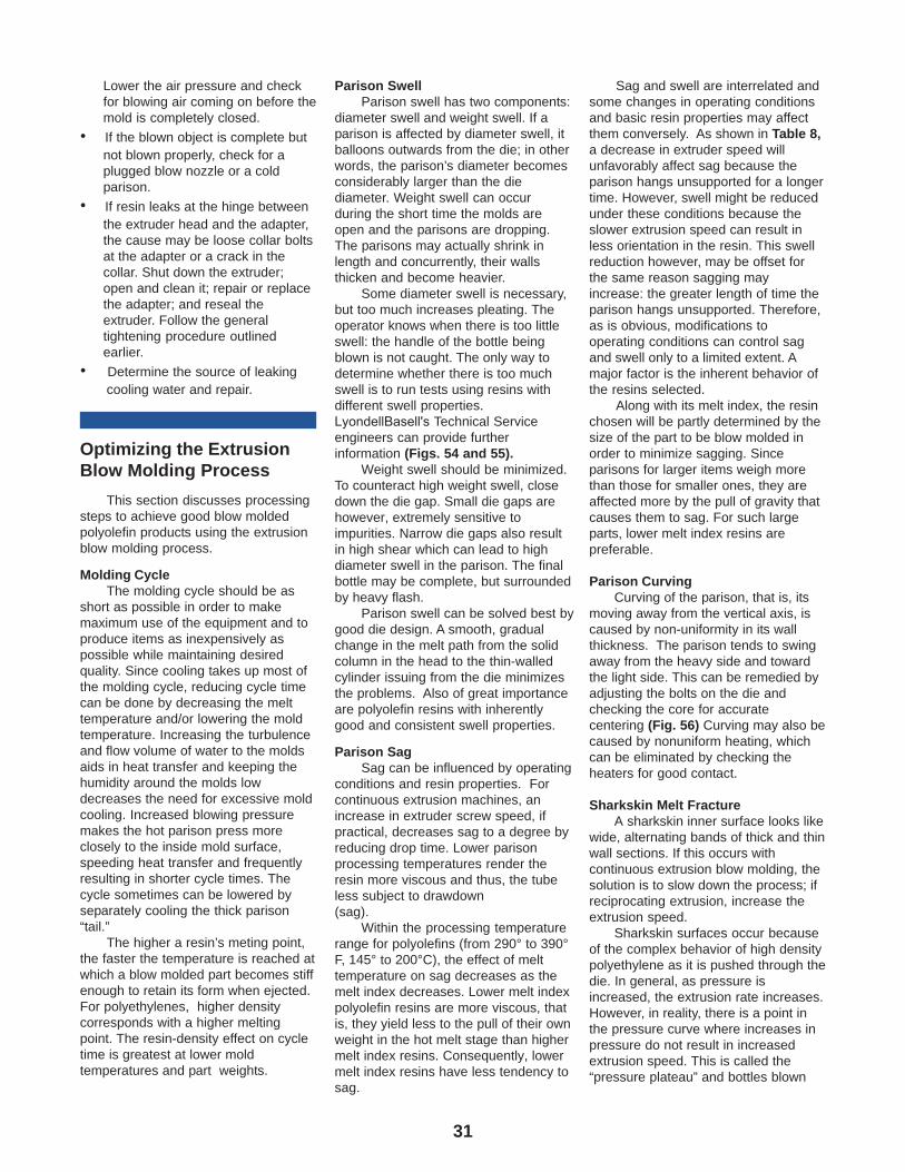
31
Lower the air pressure and checkfor blowing air coming on before themold is completely closed.
• If the blown object is complete butnot blown properly, check for aplugged blow nozzle or a coldparison.
• If resin leaks at the hinge betweenthe extruder head and the adapter,the cause may be loose collar boltsat the adapter or a crack in thecollar. Shut down the extruder;open and clean it; repair or replacethe adapter; and reseal theextruder. Follow the generaltightening procedure outlinedearlier.
• Determine the source of leakingcooling water and repair.
Optimizing the ExtrusionBlow Molding Process
This section discusses processingsteps to achieve good blow moldedpolyolefin products using the extrusionblow molding process.
Molding CycleThe molding cycle should be as
short as possible in order to makemaximum use of the equipment and toproduce items as inexpensively aspossible while maintaining desiredquality. Since cooling takes up most ofthe molding cycle, reducing cycle timecan be done by decreasing the melttemperature and/or lowering the moldtemperature. Increasing the turbulenceand flow volume of water to the moldsaids in heat transfer and keeping thehumidity around the molds lowdecreases the need for excessive moldcooling. Increased blowing pressuremakes the hot parison press moreclosely to the inside mold surface,speeding heat transfer and frequentlyresulting in shorter cycle times. Thecycle sometimes can be lowered byseparately cooling the thick parison“tail.”
The higher a resin’s meting point,the faster the temperature is reached atwhich a blow molded part becomes stiffenough to retain its form when ejected.For polyethylenes, higher densitycorresponds with a higher meltingpoint. The resin-density effect on cycletime is greatest at lower moldtemperatures and part weights.
Parison SwellParison swell has two components:
diameter swell and weight swell. If a parison is affected by diameter swell, it balloons outwards from the die; in other words, the parison’s diameter becomes considerably larger than the die diameter. Weight swell can occur during the short time the molds are open and the parisons are dropping. The parisons may actually shrink in length and concurrently, their walls thicken and become heavier.
Some diameter swell is necessary, but too much increases pleating. The operator knows when there is too little swell: the handle of the bottle being blown is not caught. The only way to determine whether there is too much swell is to run tests using resins with different swell properties. LyondellBasell's Technical Service engineers can provide further information (Figs. 54 and 55).
Weight swell should be minimized. To counteract high weight swell, close down the die gap. Small die gaps are however, extremely sensitive to impurities. Narrow die gaps also result in high shear which can lead to high diameter swell in the parison. The final bottle may be complete, but surrounded by heavy flash.
Parison swell can be solved best by good die design. A smooth, gradual change in the melt path from the solid column in the head to the thin-walled cylinder issuing from the die minimizes the problems. Also of great importance are polyolefin resins with inherently good and consistent swell properties.
Parison SagSag can be influenced by operating
conditions and resin properties. For continuous extrusion machines, an increase in extruder screw speed, if practical, decreases sag to a degree by reducing drop time. Lower parison processing temperatures render the resin more viscous and thus, the tube less subject to drawdown(sag).
Within the processing temperature range for polyolefins (from 290° to 390°F, 145° to 200°C), the effect of melt temperature on sag decreases as the melt index decreases. Lower melt index polyolefin resins are more viscous, that is, they yield less to the pull of their own weight in the hot melt stage than higher melt index resins. Consequently, lower melt index resins have less tendency to sag.
Sag and swell are interrelated andsome changes in operating conditionsand basic resin properties may affectthem conversely. As shown in Table 8,a decrease in extruder speed willunfavorably affect sag because theparison hangs unsupported for a longertime. However, swell might be reducedunder these conditions because theslower extrusion speed can result inless orientation in the resin. This swellreduction however, may be offset forthe same reason sagging mayincrease: the greater length of time theparison hangs unsupported. Therefore,as is obvious, modifications tooperating conditions can control sagand swell only to a limited extent. Amajor factor is the inherent behavior ofthe resins selected.
Along with its melt index, the resinchosen will be partly determined by thesize of the part to be blow molded inorder to minimize sagging. Sinceparisons for larger items weigh morethan those for smaller ones, they areaffected more by the pull of gravity thatcauses them to sag. For such largeparts, lower melt index resins arepreferable.
Parison CurvingCurving of the parison, that is, its
moving away from the vertical axis, iscaused by non-uniformity in its wallthickness. The parison tends to swingaway from the heavy side and towardthe light side. This can be remedied byadjusting the bolts on the die andchecking the core for accuratecentering (Fig. 56) Curving may also becaused by nonuniform heating, whichcan be eliminated by checking theheaters for good contact.
Sharkskin Melt FractureA sharkskin inner surface looks like
wide, alternating bands of thick and thinwall sections. If this occurs withcontinuous extrusion blow molding, thesolution is to slow down the process; ifreciprocating extrusion, increase theextrusion speed.
Sharkskin surfaces occur becauseof the complex behavior of high densitypolyethylene as it is pushed through thedie. In general, as pressure isincreased, the extrusion rate increases.However, in reality, there is a point inthe pressure curve where increases inpressure do not result in increasedextrusion speed. This is called the“pressure plateau” and bottles blown
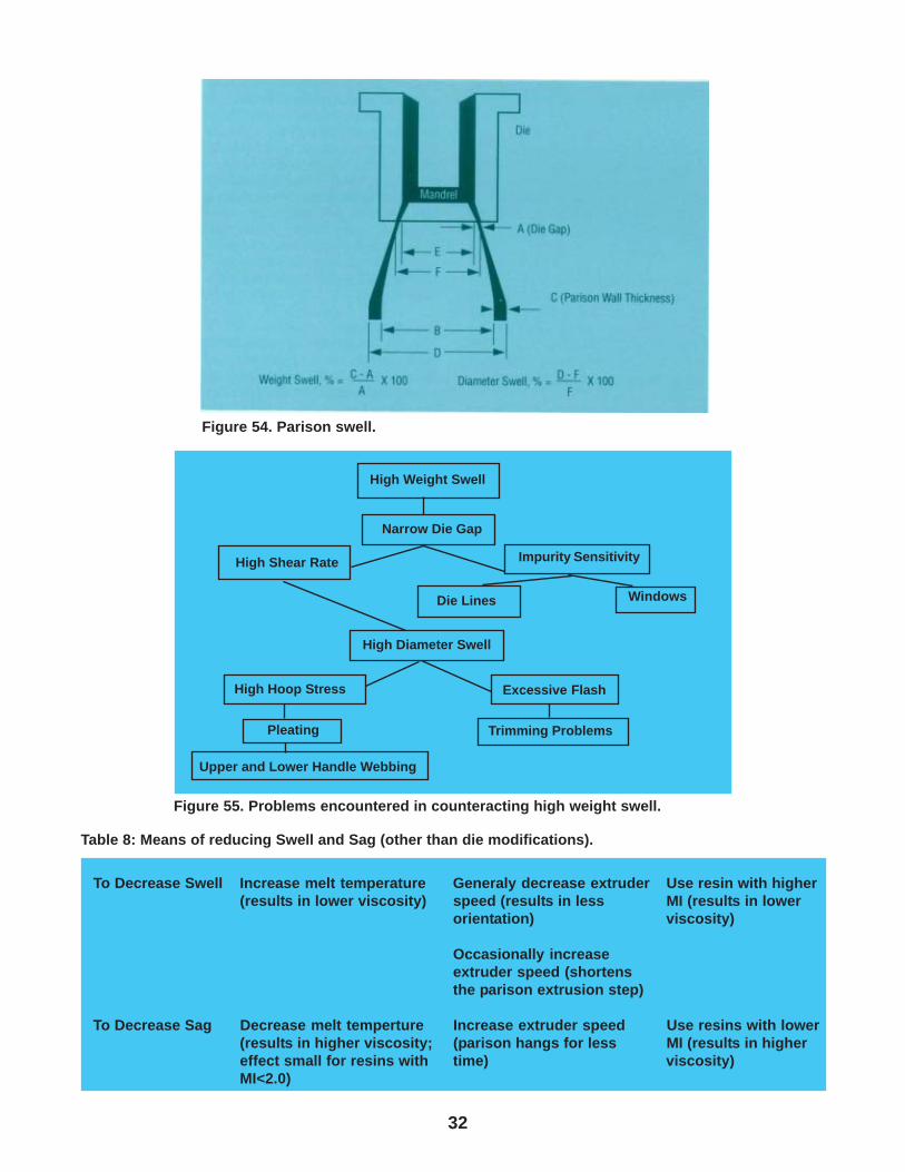
32
To Decrease Swell Increase melt temperature Generaly decrease extruder Use resin with higher(results in lower viscosity) speed (results in less MI (results in lower
orientation) viscosity)
Occasionally increaseextruder speed (shortensthe parison extrusion step)
To Decrease Sag Decrease melt temperture Increase extruder speed Use resins with lower(results in higher viscosity; (parison hangs for less MI (results in highereffect small for resins with time) viscosity)MI<2.0)
Table 8: Means of reducing Swell and Sag (other than die modifications).
Figure 55. Problems encountered in counteracting high weight swell.
High Weight Swell
Narrow Die Gap
High Shear Rate Impurity Sensitivity
WindowsDie Lines
High Diameter Swell
High Hoop Stress Excessive Flash
Trimming Problems
Upper and Lower Handle Webbing
Pleating
Figure 54. Parison swell.
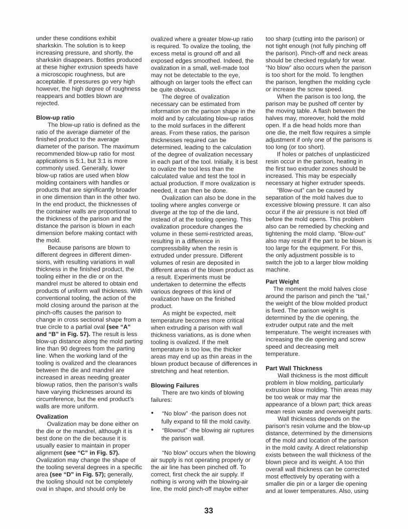
33
under these conditions exhibitsharkskin. The solution is to keepincreasing pressure, and shortly, thesharkskin disappears. Bottles producedat these higher extrusion speeds havea microscopic roughness, but areacceptable. If pressures go very highhowever, the high degree of roughnessreappears and bottles blown arerejected.
Blow-up ratioThe blow-up ratio is defined as the
ratio of the average diameter of thefinished product to the averagediameter of the parison. The maximumrecommended blow-up ratio for mostapplications is 5:1, but 3:1 is morecommonly used. Generally, lowerblow-up ratios are used when blowmolding containers with handles orproducts that are significantly broaderin one dimension than in the other two.In the end product, the thicknesses ofthe container walls are proportional tothe thickness of the parison and thedistance the parison is blown in eachdimension before making contact withthe mold.
Because parisons are blown todifferent degrees in different dimen-sions, with resulting variations in wallthickness in the finished product, thetooling either in the die or on themandrel must be altered to obtain endproducts of uniform wall thickness. Withconventional tooling, the action of themold closing around the parison at thepinch-offs causes the parison tochange in cross sectional shape from atrue circle to a partial oval (see “A”and “B” in Fig. 57). The result is lessblow-up distance along the mold partingline than 90 degrees from the partingline. When the working land of thetooling is ovalized and the clearancesbetween the die and mandrel areincreased in areas needing greaterblowup ratios, then the parison’s wallshave varying thicknesses around itscircumference, but the end product’swalls are more uniform.
OvalizationOvalization may be done either on
the die or the mandrel, although it isbest done on the die because it isusually easier to maintain in properalignment (see “C” in Fig. 57).Ovalization may change the shape ofthe tooling several degrees in a specificarea (see “D” in Fig. 57); generally,the tooling should not be completelyoval in shape, and should only be
ovalized where a greater blow-up ratiois required. To ovalize the tooling, theexcess metal is ground off and allexposed edges smoothed. Indeed, theovalization in a small, well-made toolmay not be detectable to the eye,although on larger tools the effect canbe quite obvious.
The degree of ovalizationnecessary can be estimated frominformation on the parison shape in themold and by calculating blow-up ratiosto the mold surfaces in the differentareas. From these ratios, the parisonthicknesses required can bedetermined, leading to the calculationof the degree of ovalization necessaryin each part of the tool. Initially, it is bestto ovalize the tool less than thecalculated value and test the tool inactual production. If more ovalization isneeded, it can then be done.
Ovalization can also be done in thetooling where angles converge ordiverge at the top of the die land,instead of at the tooling opening. Thisovalization procedure changes thevolume in these semi-restricted areas,resulting in a difference incompressibility when the resin isextruded under pressure. Differentvolumes of resin are deposited indifferent areas of the blown product asa result. Experiments must beundertaken to determine the effectsvarious degrees of this kind ofovalization have on the finishedproduct.
As might be expected, melttemperature becomes more criticalwhen extruding a parison with wallthickness variations, as is done whentooling is ovalized. If the melttemperature is too low, the thickerareas may end up as thin areas in theblown product because of differences instretching and heat retention.
Blowing FailuresThere are two kinds of blowing
failures:
• “No blow” -the parison does notfully expand to fill the mold cavity.
• “Blowout” -the blowing air rupturesthe parison wall.
“No blow” occurs when the blowingair supply is not operating properly orthe air line has been pinched off. Tocorrect, first check the air supply. Ifnothing is wrong with the blowing-airline, the mold pinch-off maybe either
too sharp (cutting into the parison) ornot tight enough (not fully pinching offthe parison). Pinch-off and neck areasshould be checked regularly for wear.“No blow” also occurs when the parisonis too short for the mold. To lengthenthe parison, lengthen the molding cycleor increase the screw speed.
When the parison is too long, theparison may be pushed off center bythe moving table. A flash between thehalves may, moreover, hold the moldopen. If a die head holds more thanone die, the melt flow requires a simpleadjustment if only one of the parisons istoo long (or too short).
If holes or patches of unplasticizedresin occur in the parison, heating inthe first two extruder zones should beincreased. This may be especiallynecessary at higher extruder speeds.
“Blow-out” can be caused byseparation of the mold halves due toexcessive blowing pressure. It can alsooccur if the air pressure is not bled offbefore the mold opens. This problemalso can be remedied by checking andtightening the mold clamp. “Blow-out”also may result if the part to be blown istoo large for the equipment. For this,the only adjustment possible is toswitch the job to a larger blow moldingmachine.
Part WeightThe moment the mold halves close
around the parison and pinch the “tail,”the weight of the blow molded productis fixed. The parison weight isdetermined by the die opening, theextruder output rate and the melttemperature. The weight increases withincreasing the die opening and screwspeed and decreasing melttemperature.
Part Wall ThicknessWall thickness is the most difficult
problem in blow molding, particularlyextrusion blow molding. Thin areas maybe too weak or may mar theappearance of a blown part; thick areasmean resin waste and overweight parts.
Wall thickness depends on theparison’s resin volume and the blow-updistance, determined by the dimensionsof the mold and location of the parisonin the mold cavity. A direct relationshipexists between the wall thickness of theblown piece and its weight. A too thinoverall wall thickness can be correctedmost effectively by operating with asmaller die pin or a larger die openingand at lower temperatures. Also, using
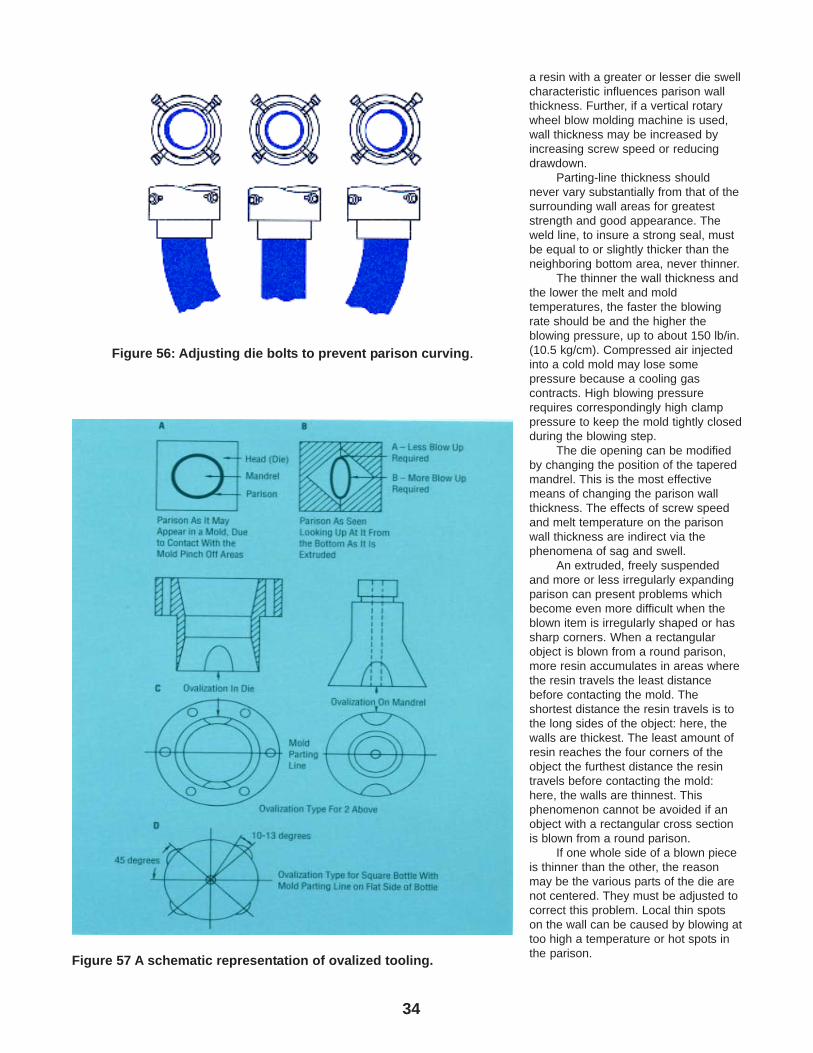
34
a resin with a greater or lesser die swellcharacteristic influences parison wallthickness. Further, if a vertical rotarywheel blow molding machine is used,wall thickness may be increased byincreasing screw speed or reducingdrawdown.
Parting-line thickness shouldnever vary substantially from that of thesurrounding wall areas for greateststrength and good appearance. Theweld line, to insure a strong seal, mustbe equal to or slightly thicker than theneighboring bottom area, never thinner.
The thinner the wall thickness andthe lower the melt and moldtemperatures, the faster the blowingrate should be and the higher theblowing pressure, up to about 150 lb/in.(10.5 kg/cm). Compressed air injectedinto a cold mold may lose somepressure because a cooling gascontracts. High blowing pressurerequires correspondingly high clamppressure to keep the mold tightly closedduring the blowing step.
The die opening can be modifiedby changing the position of the taperedmandrel. This is the most effectivemeans of changing the parison wallthickness. The effects of screw speedand melt temperature on the parisonwall thickness are indirect via thephenomena of sag and swell.
An extruded, freely suspendedand more or less irregularly expandingparison can present problems whichbecome even more difficult when theblown item is irregularly shaped or hassharp corners. When a rectangularobject is blown from a round parison,more resin accumulates in areas wherethe resin travels the least distancebefore contacting the mold. Theshortest distance the resin travels is tothe long sides of the object: here, thewalls are thickest. The least amount ofresin reaches the four corners of theobject the furthest distance the resintravels before contacting the mold:here, the walls are thinnest. Thisphenomenon cannot be avoided if anobject with a rectangular cross sectionis blown from a round parison.
If one whole side of a blown pieceis thinner than the other, the reasonmay be the various parts of the die arenot centered. They must be adjusted tocorrect this problem. Local thin spotson the wall can be caused by blowing attoo high a temperature or hot spots inthe parison.
Figure 56: Adjusting die bolts to prevent parison curving.
Figure 57 A schematic representation of ovalized tooling.
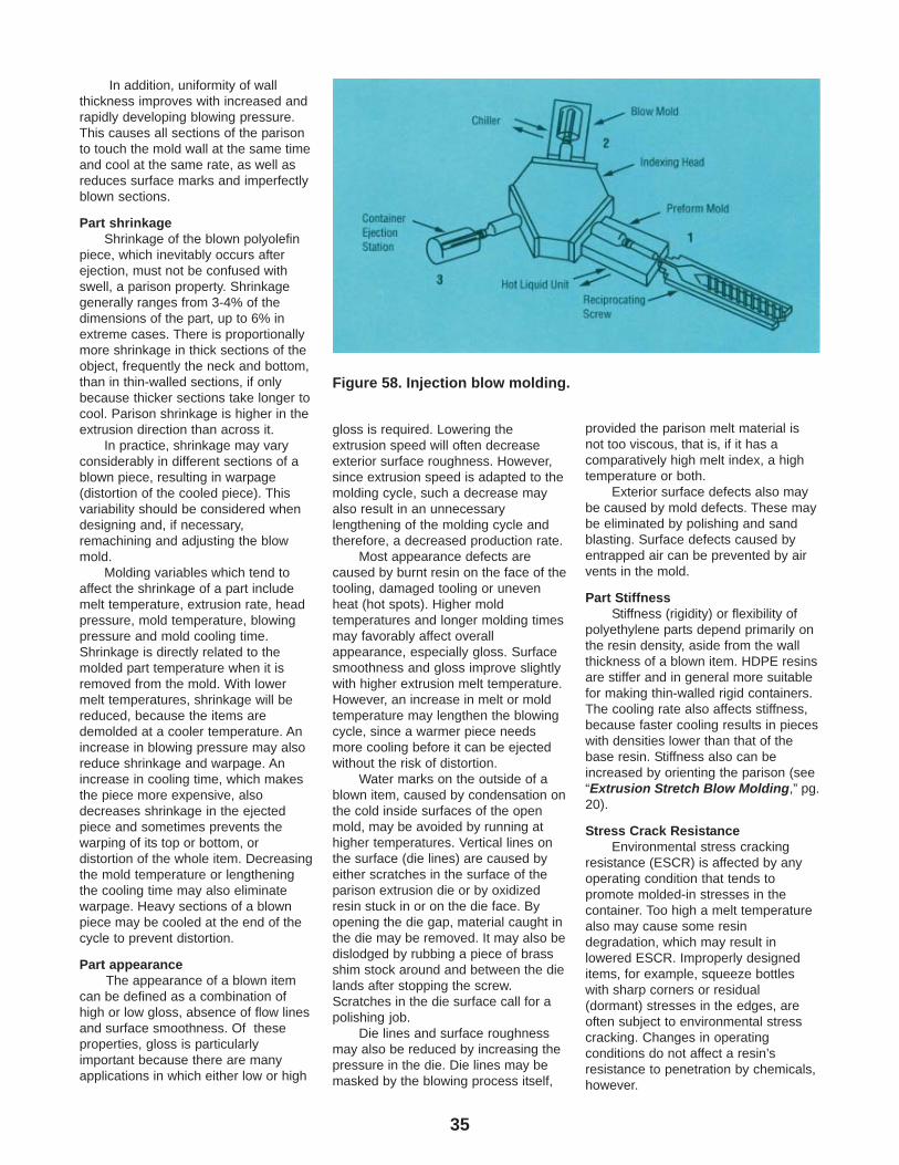
35
In addition, uniformity of wallthickness improves with increased andrapidly developing blowing pressure.This causes all sections of the parisonto touch the mold wall at the same timeand cool at the same rate, as well asreduces surface marks and imperfectlyblown sections.
Part shrinkageShrinkage of the blown polyolefin
piece, which inevitably occurs afterejection, must not be confused withswell, a parison property. Shrinkagegenerally ranges from 3-4% of thedimensions of the part, up to 6% inextreme cases. There is proportionallymore shrinkage in thick sections of theobject, frequently the neck and bottom,than in thin-walled sections, if onlybecause thicker sections take longer tocool. Parison shrinkage is higher in theextrusion direction than across it.
In practice, shrinkage may varyconsiderably in different sections of ablown piece, resulting in warpage(distortion of the cooled piece). Thisvariability should be considered whendesigning and, if necessary,remachining and adjusting the blowmold.
Molding variables which tend toaffect the shrinkage of a part includemelt temperature, extrusion rate, headpressure, mold temperature, blowingpressure and mold cooling time.Shrinkage is directly related to themolded part temperature when it isremoved from the mold. With lowermelt temperatures, shrinkage will bereduced, because the items aredemolded at a cooler temperature. Anincrease in blowing pressure may alsoreduce shrinkage and warpage. Anincrease in cooling time, which makesthe piece more expensive, alsodecreases shrinkage in the ejectedpiece and sometimes prevents thewarping of its top or bottom, ordistortion of the whole item. Decreasingthe mold temperature or lengtheningthe cooling time may also eliminatewarpage. Heavy sections of a blownpiece may be cooled at the end of thecycle to prevent distortion.
Part appearanceThe appearance of a blown item
can be defined as a combination ofhigh or low gloss, absence of flow linesand surface smoothness. Of theseproperties, gloss is particularlyimportant because there are manyapplications in which either low or high
gloss is required. Lowering theextrusion speed will often decreaseexterior surface roughness. However,since extrusion speed is adapted to themolding cycle, such a decrease mayalso result in an unnecessarylengthening of the molding cycle andtherefore, a decreased production rate.
Most appearance defects arecaused by burnt resin on the face of thetooling, damaged tooling or unevenheat (hot spots). Higher moldtemperatures and longer molding timesmay favorably affect overallappearance, especially gloss. Surfacesmoothness and gloss improve slightlywith higher extrusion melt temperature.However, an increase in melt or moldtemperature may lengthen the blowingcycle, since a warmer piece needsmore cooling before it can be ejectedwithout the risk of distortion.
Water marks on the outside of ablown item, caused by condensation onthe cold inside surfaces of the openmold, may be avoided by running athigher temperatures. Vertical lines onthe surface (die lines) are caused byeither scratches in the surface of theparison extrusion die or by oxidizedresin stuck in or on the die face. Byopening the die gap, material caught inthe die may be removed. It may also bedislodged by rubbing a piece of brassshim stock around and between the dielands after stopping the screw.Scratches in the die surface call for apolishing job.
Die lines and surface roughnessmay also be reduced by increasing thepressure in the die. Die lines may bemasked by the blowing process itself,
provided the parison melt material isnot too viscous, that is, if it has acomparatively high melt index, a hightemperature or both.
Exterior surface defects also maybe caused by mold defects. These maybe eliminated by polishing and sandblasting. Surface defects caused byentrapped air can be prevented by airvents in the mold.
Part StiffnessStiffness (rigidity) or flexibility of
polyethylene parts depend primarily onthe resin density, aside from the wallthickness of a blown item. HDPE resinsare stiffer and in general more suitablefor making thin-walled rigid containers.The cooling rate also affects stiffness,because faster cooling results in pieceswith densities lower than that of thebase resin. Stiffness also can beincreased by orienting the parison (see“Extrusion Stretch Blow Molding,” pg.20).
Stress Crack ResistanceEnvironmental stress cracking
resistance (ESCR) is affected by anyoperating condition that tends topromote molded-in stresses in thecontainer. Too high a melt temperaturealso may cause some resindegradation, which may result inlowered ESCR. Improperly designeditems, for example, squeeze bottleswith sharp corners or residual(dormant) stresses in the edges, areoften subject to environmental stresscracking. Changes in operatingconditions do not affect a resin’sresistance to penetration by chemicals,however.
Figure 58. Injection blow molding.
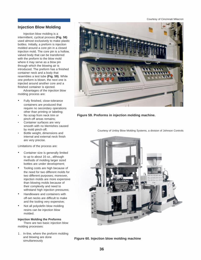
36
Injection Blow Molding
Injection blow molding is aintermittent, cyclical process (Fig. 58)used almost exclusively to make plasticbottles. Initially, a preform is injectionmolded around a core pin in a closedinjection mold. The core pin is a hollow,valved body that can be transferredwith the preform to the blow moldwhere it may serve as a blow pinthrough which the blowing air isintroduced. The preform has a finishedcontainer neck and a body thatresembles a test tube (Fig. 59). Whileone preform is blown, the next one isinjected around another core and afinished container is ejected.
Advantages of the injection blowmolding process are:
• Fully finished, close-tolerancecontainers are produced thatrequire no secondary operationsother than printing or labeling;
• No scrap from neck trim orpinch-off areas remains;
• Container surfaces are verysmooth with no blemishes causedby mold pinch-off;
• Bottle weight, dimensions andinternal and external neck finishare very precise.
Limitations of the process are:
• Container size is generally limitedto up to about 16 oz., althoughmethods of molding larger sizedbottles are under development;
• Tooling costs are high because ofthe need for two different molds fortwo different purposes; moreover,injection molds are more expensivethan blowing molds because oftheir complexity and need towithstand high injection pressures;
• Handleware and containers withoff-set necks are difficult to makeand the tooling very expensive;
• Not all polyolefin blow moldingresins can be injection blowmolded.
Injection Molding the PreformsThere are two basic injection blow
molding processes:
1 . In-line, where the preform moldingand blowing are donesimultaneously
Figure 59. Preforms in injection molding machine.
Courtesy of Cincinnati Milacron
Figure 60. Injection blow molding machine
Courtesy of Uniloy Blow Molding Systems, a division of Johnson Controls
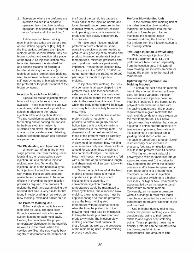
37
2. Two-stage, where the preforms areinjection molded in a separateoperation from the blow moldingoperation; this technique is referredto as “reheat and blow molding.”
In-line injection blow moldingmachines in use today are either threeor four-station equipment (Fig. 60). Atthe first station, preforms are injectionmolded; at the second station, they areblown; cooling and ejection take placeat the third. A co-injection station maybe added between the standard firstand second stations for forming ahandle, stretching the parison (atechnique called “stretch blow molding,”used to improve container clarity and/orstiffness by means of biaxially orientingthe preform) or for post-treatment of theblown container.
Injection Stretch Blow MoldingSpecial six-station injection stretch
blow molding machines also areavailable. These machines include twoconditioning stations and a post-blowstation in addition to the regularinjection, blow and ejection stations.The two conditioning stations are usedfor heating and/or cooling the parison.In the blow step, the parison isstretched and blown into the desiredshape. In the post-blow step, labeling,surface treatment and/or leak detectionare performed.
The Plasticating and Injection UnitWhether part of an in-line or two-
stage process, the resin melting unit isidentical to the reciprocating screwinjection unit of a standard injectionmolding machine. Generally, theinjection unit is of the horizontal type,but injection blow molding machineswith vertical injection units also areavailable and considered to be moreefficient in providing the low injectionpressures required. The process ofmelting the resin and accumulating theneeded shot size is very similar to thatfound in reciprocating screw extrusionblow molding, explained earlier on p.23.
The Preform Molding UnitEither a single or multiple cavity
mold can be used. The melt flowsthrough a manifold with a hot runnersystem leading to each mold cavity.Heating fluid maintains the propertemperature distribution in the manifoldas well as in the mold. When thecavities are filled, the screw pulls backslightly to decompress the chamber at
the front of the barrel; this causes a“suck back” at the injection nozzle andlocks the melt, under pressure, in themanifold system. Consistent, reliablemold packing pressure is essential toproducing high quality containers bythis process.
To make good injection moldedpreforms requires about the sameoperating conditions as are needed toproduce any good injection molded endproduct. However, moderate injectiontemperatures, minimum pressures andwarm preform molds are particularlyimportant. Pressures for injection blowmolding are in the 5,000 to 10,000 psirange, rather than the 15,000 to 20,000psi range for standard injectionmolding.
In injection blow molding, the neckof a container is already shaped in thepreform mold. This fact necessitatesselective mold cooling: the neck areamust be cooled so that the resin theresets. At the same time, the resin fromwhich the body of the item will be blownmust stay hot until it is fully blown in theblow mold.
Because the wall thickness of thepreform body is not uniform, it ispossible to obtain irregularly shapedhollow items with practically uniformwall thickness in the blowing mold. Thedimensions of the preform mold andthose of the preform must be carefullyand accurately tailored to do this.A blow mold for injection blow moldingequipment has only one difference froma mold for extrusion blow molding: ithas no pinch-off edges. The injectionblow mold needs none because it is fedwith a preform of predetermined lengthand shape instead of an open tube withexcess length.
Since the cycle time of all the blowmolding process steps is of majorimportance in productivity, shortinjecting time is essential. Inconventional injection molding,temperatures would be maximized tolower cycle times, but in injection blowmolding, barrel temperatures must bekept low enough so that the preformsare at the blow molding steptemperature without external cooling.Also, the time the preform is in theblowing mold must also be minimizedto keep the total cycle time short andproductivity high. The injection blowmolding operator must balance allthese factors, as well as the propertiesof the resin being used, in determiningprocess conditions.
Preform Blow Molding UnitIn the preform blow molding unit of
the in-line injection blow moldingmachine, air is injected into the hotpreform to form the part. A coremaintains the required insidedimensions during the transfer of thehot preform from the injection station tothe blowing station.
Two-Stage Injection Blow MoldingWith two-stage injection blow
molding equipment (Fig. 61), thepreforms are blow molded separatelyfrom the injection step. This type ofblow molding unit includes an oven forheating the preforms to the requiredtemperature.
Optimizing the Injection BlowMolding Process
To obtain the best possible moldeditem in the shortest time and at lowestcost, two basic variables, injectiontemperature and injection pressure,must be in balance in the barrel. Sincepolyolefins become more fluid withincreasing temperature, the pressurerequired to fill a given mold with theresin melt depends to a large extent onthe melt temperature. Four basicinjection machine variables that can beadjusted to obtain preform mold fill aretemperature, pressure, feed rate andinjection time. If a particular job isyielding “short shots,” either anincrease in temperature to obtain lowerresin viscosity or an increase inpressure, feed rate or injection timeresults in the preform mold fill desired.
The higher the melt index of apolyethylene resin (or melt flow rate ofa polypropylene resin), the better itsflow properties, the lower the injectionpressure and/or barrel temperature orboth, required to fill a preform mold.Therefore, a reduction in injectionpressure without switching to a highermelt index, or higher flow, resin must beaccompanied by an increase in barreltemperature to obtain mold fill.Conversely, an increase in pressurewithout a change in resin melt indexmust be accompanied by a reduction intemperature to prevent “flashing” of thepreform mold.
Use of higher density resins mayreduce the preform molding cycle timeconsiderably, owing to their greaterstiffness and higher heat softeningpoints. These properties mean higherdensity preforms can be transferred tothe blowing mold at highertemperatures. The amount of time
38
gained depends on the size and shapeof the injection molded article and thespeed of the machine.
For maximum production, injectionrates must be high and injectiontemperatures as low as possible; thelower limit is fixed by the requirementthat the preform must not solidify whentransferred to the blowing mold.However, an irregularly frosty surfaceon items injection blow moldedindicates the injection moldingtemperature is too low. These markscan also result from scaling occurringas the resin is pushed through thenozzle or gating. Increasing theinjection temperature to reduce meltviscosity and reducing the pressurecorrespondingly may eliminate suchroughness.
Surface roughness can also occurit the material at the nozzle of theinjection molding machine cools toomuch between cycles. This conditioncan be eliminated by installing heaterson a conventional nozzle or byrestricting the gatings lightly.
Exterior surface defects may alsobe caused by defects in either thepreform mold or the blowing mold. Bothtypes of mold defects can be eliminatedby polishing. As in extrusion blowmolding, air vents in the blowing moldallow entrapped air to escape and thuseliminate another source of surfacedefects.
Injection temperatures must behigh enough to prevent poor welds. Foreach type of polyolefin used, the mostsuitable blow molding temperaturemust be determined as a function of theblow rate. At this temperature, preformblowout is minimized as well as thinspots in the finished part.
If thin spots do occur in the wall ofan injection blown piece, thetemperature of the preform is too highwhen air is injected into the blowingmold. Uniform thickness can beobtained by either lowering the injectiontemperature or, if this is not feasible, bygiving the preform more time for coolingbefore it is blown.
Cleaning the Extruder andIts Parts
Over long periods of continuousoperation, a polyolefin extruder may,
under certain conditions, slowly buildup a layer of oxidized polymer,particularly on the inside barrel wallsand the screw. This degraded resinfinally begins to flake off. This, in turn,results in defects such as yellow-brownoxidized particles in the melt. Suchparticles can affect the appearance andthe properties of the blown item. Thedanger point has been reached whenthe screen pack has little or no effect inholding back the impurities. It nowbecomes necessary to pull the screwand give it, as well as the barrel,adapter, breaker plate and die, athorough cleaning.
Preferably, a preventivemaintenance program calls for suchcleaning before the danger point isreached. If the extruder is shut downfrequently for any length of time, thebuild-up of oxidized polymer occursmuch more often. This means all theparts must be cleaned more frequently.The time between thorough cleaningscan best be determined by experience.If the extruder is continuously in useover long periods, every two monthsmight be a good cleaning schedule.The appearance of the ejected blownpieces is the best indicator. If there is apressure gauge, an increase inpressure may indicate that it is time toclean the breaker plate and change thescreen pack.
How to Clean the Extruder, Screwand Barrel
To clean the extruder, the followingsteps are recommended:
1 . Let the extruder run with resin atapproximately 300°F (150°C) forLDPE and MDPE resins and 380°F(195°C) for HDPE, without furtherfeeding until the screw can beseen at the bottom of the hopper.Never let the screw run “dry.”
2. Turn off all electricity and water.While the machine is still hot, rollaway or remove any equipment inline with the screw. Never touchany hot part of the machine unlesswearing protective gloves.
3. Disconnect electrical lineswherever necessary.
4. Remove the die head and dies. Formoving heavy machine parts,heavy duty equipment is needed,such as an overhead crane, a lifttruck or a chain hoist.
5. Remove the adapter from thebarrel.
6. Remove the breaker plate with thescreens.
7. Push the screw forward from theback end and remove it. Allextruder parts to be cleaned orexchanged are now accessible.
8. To clean the screw, first use a copper or brass bladed scraper toremove most of the molten resinadhering to the screw. After scraping off the bulk of the polymer melt,clean the screw with copper orbrass (not steel) wool. Use asilicone grease spray to helpremove tightly adhering resin. Next,coat the screw with silicone greasebefore replacing it. Never use steeltools or steel wool to clean any partof the extruder.
9. Always clean the barrel wheneverthe screw is cleaned. Run along-handled brass brush throughthe barrel to remove the remainingresin. Then use a similar tool tolubricate it with silicone grease.
10. Clean the adapter with copper orbrass tools similar to those usedfor cleaning the screw. Thenlubricate with silicone grease.Clean the collar. Clean andlubricate the seat of the adapterand breaker plate, also the end ofthe screw if the screw has not beenremoved for cleaning orexchanging by the procedure justdescribed.
11. The face of the adapter as well asthat of the barrel is clean andneeds no further attention if fittedaccurately during the previous run.Exchange, do not clean, the screenpack. Used screen packs must beremoved from the breaker plate atregular intervals, otherwise theybecome an obstruction instead of afilter. Since they are bound to bedamaged when removed, discardthem. The screen pack should beremoved from the breaker platewith a sharp brass knife. Never useany device such as a screwdriver.Steel may damage the breakerplate and result in defective blowmolded pieces and rejects. Thescreen pack should be changedabout once each week, if theextruder is in continuous operation.
When changing the screen packbetween extruder cleanings, thefollowing steps are recommended,provided breaker plate and screen packare located between extruder head andadapter:
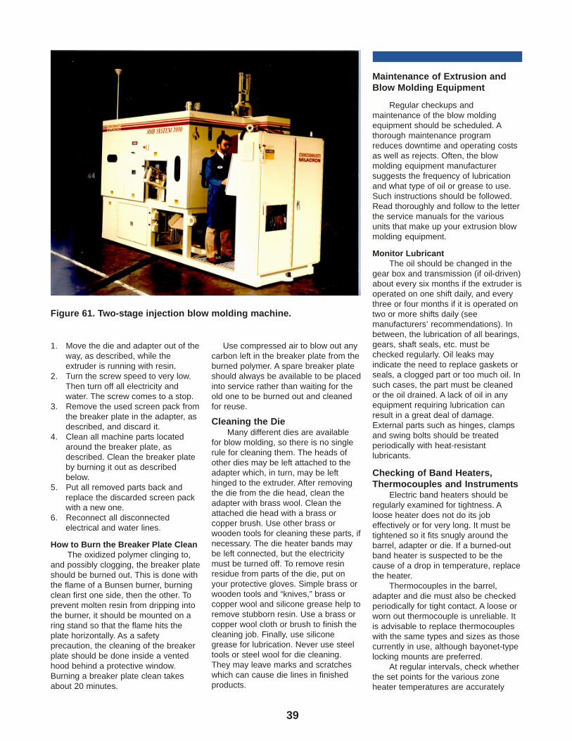
39
1. Move the die and adapter out of theway, as described, while theextruder is running with resin.
2. Turn the screw speed to very low.Then turn off all electricity andwater. The screw comes to a stop.
3. Remove the used screen pack fromthe breaker plate in the adapter, asdescribed, and discard it.
4. Clean all machine parts locatedaround the breaker plate, asdescribed. Clean the breaker plateby burning it out as describedbelow.
5. Put all removed parts back andreplace the discarded screen packwith a new one.
6. Reconnect all disconnectedelectrical and water lines.
How to Burn the Breaker Plate CleanThe oxidized polymer clinging to,
and possibly clogging, the breaker plateshould be burned out. This is done withthe flame of a Bunsen burner, burningclean first one side, then the other. Toprevent molten resin from dripping intothe burner, it should be mounted on aring stand so that the flame hits theplate horizontally. As a safetyprecaution, the cleaning of the breakerplate should be done inside a ventedhood behind a protective window.Burning a breaker plate clean takesabout 20 minutes.
Use compressed air to blow out anycarbon left in the breaker plate from theburned polymer. A spare breaker plateshould always be available to be placedinto service rather than waiting for theold one to be burned out and cleanedfor reuse.
Cleaning the DieMany different dies are available
for blow molding, so there is no singlerule for cleaning them. The heads ofother dies may be left attached to theadapter which, in turn, may be lefthinged to the extruder. After removingthe die from the die head, clean theadapter with brass wool. Clean theattached die head with a brass orcopper brush. Use other brass orwooden tools for cleaning these parts, ifnecessary. The die heater bands maybe left connected, but the electricitymust be turned off. To remove resinresidue from parts of the die, put onyour protective gloves. Simple brass orwooden tools and “knives,” brass orcopper wool and silicone grease help toremove stubborn resin. Use a brass orcopper wool cloth or brush to finish thecleaning job. Finally, use siliconegrease for lubrication. Never use steeltools or steel wool for die cleaning.They may leave marks and scratcheswhich can cause die lines in finishedproducts.
Maintenance of Extrusion andBlow Molding Equipment
Regular checkups andmaintenance of the blow moldingequipment should be scheduled. Athorough maintenance programreduces downtime and operating costsas well as rejects. Often, the blowmolding equipment manufacturersuggests the frequency of lubricationand what type of oil or grease to use.Such instructions should be followed.Read thoroughly and follow to the letterthe service manuals for the variousunits that make up your extrusion blowmolding equipment.
Monitor LubricantThe oil should be changed in the
gear box and transmission (if oil-driven)about every six months if the extruder isoperated on one shift daily, and everythree or four months if it is operated ontwo or more shifts daily (seemanufacturers’ recommendations). Inbetween, the lubrication of all bearings,gears, shaft seals, etc. must bechecked regularly. Oil leaks mayindicate the need to replace gaskets orseals, a clogged part or too much oil. Insuch cases, the part must be cleanedor the oil drained. A lack of oil in anyequipment requiring lubrication canresult in a great deal of damage.External parts such as hinges, clampsand swing bolts should be treatedperiodically with heat-resistantlubricants.
Checking of Band Heaters,Thermocouples and Instruments
Electric band heaters should beregularly examined for tightness. Aloose heater does not do its jobeffectively or for very long. It must betightened so it fits snugly around thebarrel, adapter or die. If a burned-outband heater is suspected to be thecause of a drop in temperature, replacethe heater.
Thermocouples in the barrel,adapter and die must also be checkedperiodically for tight contact. A loose orworn out thermocouple is unreliable. Itis advisable to replace thermocoupleswith the same types and sizes as thosecurrently in use, although bayonet-typelocking mounts are preferred.
At regular intervals, check whetherthe set points for the various zoneheater temperatures are accurately
Figure 61. Two-stage injection blow molding machine.
40
shown on the indicator dials on thetemperature control board. Proceduresfor checking thermocouples, lead wiresand instruments for calibration can befound in instrument manuals. If analarm system for faulty operatingheaters, blown fuses or breakers isprovided, such as a flickering bulb,buzzer, horn or ammeters, react to thewarning signals immediately.Determine, by means of theinstruments on the temperature controlboard, which of the heaters is failing.
The alignment, level and, wherevernecessary, placement of the variousmain parts of the extruder and blowmolding equipment should be checkedregularly and must be corrected whenrequired. Check the die opening with aflexible gauge whenever the parisonextrudes with non-uniform wallthickness, causing it to curve.
An adequate amount of clean oilmust be kept in the hydraulic system.The equipment manufacturer usuallyrecommends a specific type of oil in themaintenance manual. The air in thepneumatic system that operates valves,automatic stripping, the cut-off knifeand other parts of the blowingequipment should be lightly oiled,provided the blow molding air issupplied by a separate system. Thismeans the pneumatic system mustcontain an oiler and a water strainer toprotect the oil from watercontamination. The blowing air shouldnot be oiled. The operator mustconstantly watch both the hydraulic andpneumatic systems for pressurechanges caused by faulty valves andgauges or by leaks, as indicated oninstruments.
A closed water circuit is frequentlypreferable to using tap water in thecooling system. Tap water requires acleaning tower in the system. Wellwater is often “hard,” and mineraldeposits might lessen the effectivenessof the heat exchanger for the oil in thehydraulic system. Watch the moldcooling water temperature either bymeans of instruments, such asthermocouples or pyrometers, ormanually by occasionally touching thewater line surfaces. Do not touch themold surfaces for this purpose.
Cleanliness in the blow moldingshop is a most important part of themaintenance job. Contamination of theresin by dust, dirt and especially, smallmetal parts make the production ofgood products impossible; it may also
damage the screw, the die and otherparts of the extruder. It is alwaysadvantageous to keep small sets ofcomparatively inexpensive spare partsin stock, such as thermocouples,heaters, fuses, die adjusting bolts,screen packs, a breakerplate, die pins,etc.
Prevent Hazards Harmful to You,Your Equipment and YourProduct
Accidents to people and equip-ment, except for those caused byuncontrollable events, can be pre-vented. Most are caused by humanerror or negligence. Always keep inmind a few basic safety rules:
• Be accident-conscious; develop a“safety sense,” and follow safeworking procedures
• At all times, keep all yourequipment, machinery, tools orauxiliary parts well maintained andclean
• The “No Smoking” signs on thewalls of a blow molding shop mustbe heeded; smoking is dangerousand can be a source of resincontamination.
The following hazards also requireconstant attention:
HeatYou are working with hot resins in a
heated machine. Unless required forcleaning or other purposes, do notremove protective covers or hoods fromthe extruder or blow molder. Whenworking around hot machine parts,always use protective gloves. Clean uplumps of purge resin left on the floornear the machine. They present asafety hazard, easily becamecontaminated and, therefore areuseless as regrind. The best procedureis to let purge drop into a tray in piecessmall enough to be easily reground.
Physical injuryNever place your hands in
hazardous areas such as near themoving platens or molds when startingup or adjusting the molding press. Infact, no machine should be run withgear guards removed. Never allowresin pellets or cubes to remain on thefloor. If you step on them, they may rolllike a ball or roller bearing withdangerous consequences. Do not start
the extruder at too low a temperature.The inside pressure built up by theviscous or solid resin may break theequipment, “shoot” the die assembly offand cause injury as well as put theextruder out of operation for a longtime.
Areas around moving equipmentmay be “injury traps,” particularly whenyou handle objects or use hand tools.Avoid wearing long neckties andloose-fitting clothing. Anything looseabout you may be caught by movingequipment and pull you into contactwith moving or hot machine parts,resulting in injury. Wear safety glassesand safety shoes while working aroundthe extruder and blow moldingequipment.
If there is a safety mechanism onyour machine, such as a “panic button”for the protection of personnel andequipment, make sure all operatorsknow how to use it. Never try to removea safety device or make it inoperablewhile the machine is running. Most blowmolding presses are equipped withpivoting or sliding safety shields, safetyscreens or gates for your protection.The machine stops whenever a shieldis removed. Do not tamper with thissafety device; some day it may saveyour hand or eye. Some blow moldingmachines have electronic safetydevices replacing the safety screen.
Poor Ventilation andUncleanliness
Dust and dirt are unhealthy foroperators and can damage yourproducts. Therefore, keep the shopclean. Do not permit waste toaccumulate on the floor around themachine. Adequate ventilation is amust. Never tamper with the exhaustequipment. Keep it clean and in goodorder.
ElectricityNever forget high voltage can be
dangerous. Damaged electricalinsulation is a major safety hazard.Beware of the high voltage-carryingelectrode bars of some types of electricheating equipment. Some moving partsof blow molding equipment are wired.Make sure these electric connectionsare good, safe and controlled. Keepwater and oil lines away from them.Water vapor in the air may condenseon cooling lines and on nearbyelectrical contacts.
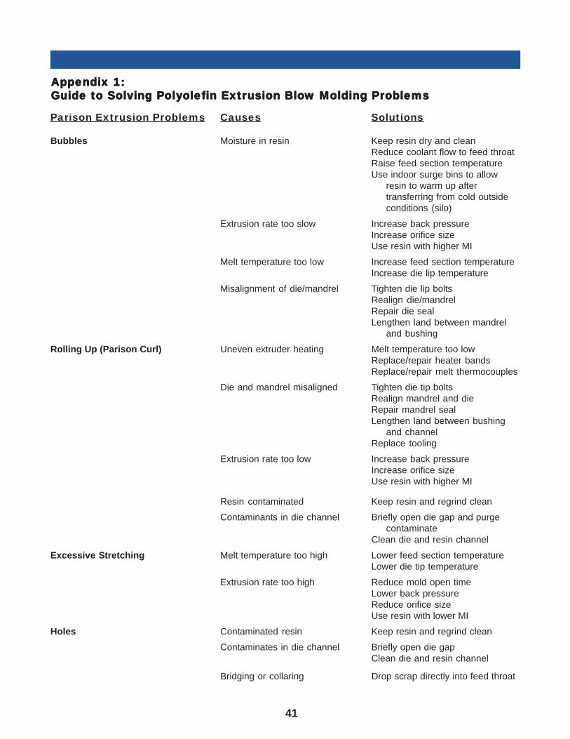
41
AAAAAppendix 1:ppendix 1:ppendix 1:ppendix 1:ppendix 1:Guide to Solving PGuide to Solving PGuide to Solving PGuide to Solving PGuide to Solving Polololololyyyyyolefolefolefolefolefin Extrin Extrin Extrin Extrin Extrusion Blousion Blousion Blousion Blousion Blow Molding Prw Molding Prw Molding Prw Molding Prw Molding Proboboboboblemslemslemslemslems
Parison Extrusion Problems Causes Solutions
Bubbles Moisture in resin Keep resin dry and cleanReduce coolant flow to feed throatRaise feed section temperatureUse indoor surge bins to allow
resin to warm up aftertransferring from cold outsideconditions (silo)
Extrusion rate too slow Increase back pressureIncrease orifice sizeUse resin with higher MI
Melt temperature too low Increase feed section temperatureIncrease die lip temperature
Misalignment of die/mandrel Tighten die lip boltsRealign die/mandrelRepair die sealLengthen land between mandrel
and bushing
Rolling Up (Parison Curl) Uneven extruder heating Melt temperature too lowReplace/repair heater bandsReplace/repair melt thermocouples
Die and mandrel misaligned Tighten die tip boltsRealign mandrel and dieRepair mandrel sealLengthen land between bushing
and channelReplace tooling
Extrusion rate too low Increase back pressureIncrease orifice sizeUse resin with higher MI
Resin contaminated Keep resin and regrind clean
Contaminants in die channel Briefly open die gap and purgecontaminate
Clean die and resin channel
Excessive Stretching Melt temperature too high Lower feed section temperatureLower die tip temperature
Extrusion rate too high Reduce mold open timeLower back pressureReduce orifice sizeUse resin with lower MI
Holes Contaminated resin Keep resin and regrind clean
Contaminates in die channel Briefly open die gapClean die and resin channel
Bridging or collaring Drop scrap directly into feed throat
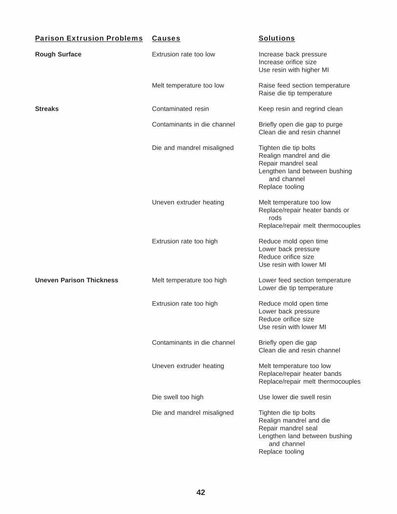
42
Parison Extrusion Problems Causes Solutions
Rough Surface Extrusion rate too low Increase back pressureIncrease orifice sizeUse resin with higher MI
Melt temperature too low Raise feed section temperatureRaise die tip temperature
Streaks Contaminated resin Keep resin and regrind clean
Contaminants in die channel Briefly open die gap to purgeClean die and resin channel
Die and mandrel misaligned Tighten die tip boltsRealign mandrel and dieRepair mandrel sealLengthen land between bushing
and channelReplace tooling
Uneven extruder heating Melt temperature too lowReplace/repair heater bands or
rodsReplace/repair melt thermocouples
Extrusion rate too high Reduce mold open timeLower back pressureReduce orifice sizeUse resin with lower MI
Uneven Parison Thickness Melt temperature too high Lower feed section temperatureLower die tip temperature
Extrusion rate too high Reduce mold open timeLower back pressureReduce orifice sizeUse resin with lower MI
Contaminants in die channel Briefly open die gapClean die and resin channel
Uneven extruder heating Melt temperature too lowReplace/repair heater bandsReplace/repair melt thermocouples
Die swell too high Use lower die swell resin
Die and mandrel misaligned Tighten die tip boltsRealign mandrel and dieRepair mandrel sealLengthen land between bushing
and channelReplace tooling
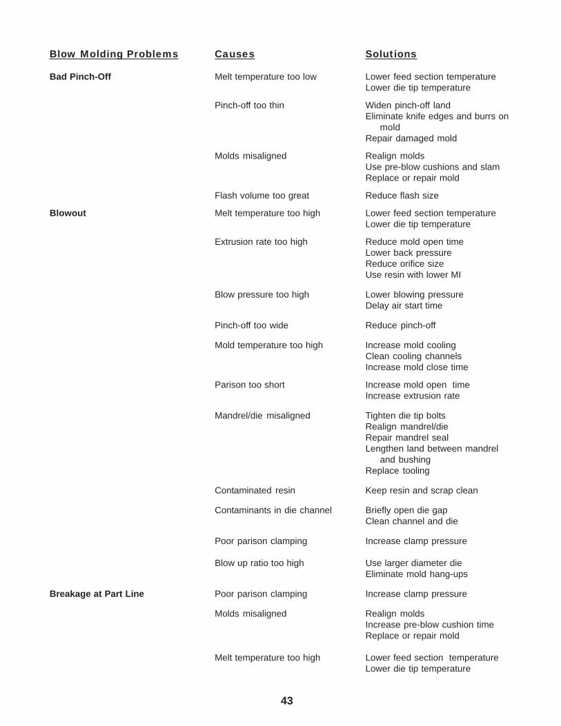
43
Blow Molding Problems Causes Solutions
Bad Pinch-Off Melt temperature too low Lower feed section temperatureLower die tip temperature
Pinch-off too thin Widen pinch-off landEliminate knife edges and burrs on
moldRepair damaged mold
Molds misaligned Realign moldsUse pre-blow cushions and slamReplace or repair mold
Flash volume too great Reduce flash size
Blowout Melt temperature too high Lower feed section temperatureLower die tip temperature
Extrusion rate too high Reduce mold open timeLower back pressureReduce orifice sizeUse resin with lower MI
Blow pressure too high Lower blowing pressureDelay air start time
Pinch-off too wide Reduce pinch-off
Mold temperature too high Increase mold coolingClean cooling channelsIncrease mold close time
Parison too short Increase mold open timeIncrease extrusion rate
Mandrel/die misaligned Tighten die tip boltsRealign mandrel/dieRepair mandrel sealLengthen land between mandrel
and bushingReplace tooling
Contaminated resin Keep resin and scrap clean
Contaminants in die channel Briefly open die gapClean channel and die
Poor parison clamping Increase clamp pressure
Blow up ratio too high Use larger diameter dieEliminate mold hang-ups
Breakage at Part Line Poor parison clamping Increase clamp pressure
Molds misaligned Realign moldsIncrease pre-blow cushion timeReplace or repair mold
Melt temperature too high Lower feed section temperatureLower die tip temperature
44
Problems Causes Solutions
Ejection From Mold Melt temperature too high Lower feed section temperatureLower die tip temperature
Mold temperature too high Increase mold coolingClean cooling channelsIncrease mold close time
Not enough draft in mold Clean blow pinsEliminate mold hang-upsAlign blow pinsRedesign molds (increase draft)
Flash Pinch-off too wide Reduce pinch-off
Weak Weld Line Melt temperature too high Lower feed section temperatureLower die tip temperature
Mold temperature too high Increase mold coolingClean cooling channelsIncrease mold close time
Pinch-off too thin Widen pinch-off landEliminate knife edges and burrs
Finished Product Problems Cause Solutions
Bubbles Moisture in resin Keep resin dryReduce coolant flow to feed throatRaise feed section temperature
Moisture in mold Increase mold temperatureVent moldsEliminate cooling water leaksDehumidity molding areaWipe mold surface
Extrusion rate too low Raise back pressureIncrease orifice sizeUse resin with higher MI
Misaligned die/mandrel Tighten die tip boltsRealign die/mandrelRepair mandrel sealLengthen land between mandrel
and dieReplace tooling
Flashing on Product Melt temperature too high Lower feed section temperatureLower die tip temperature
Mold Misaligned Realign moldUse pre-blow cushion and slamrepair or replace mold
45
Problems Causes Solutions
Product Breaks Weld Line Poor parison clamping Increase clamp pressureCheck pinch-off areas
Mold misaligned Realign moldUse pre-blow cushion and slamRepair or replace mold
Melt temperature too low Lower feed section temperatureLower die tip temperatureReduce cycle time
Shrinkage Melt temperature too High Lower feed section temperatureClean cooling channelsIncrease mold close time
Blow pressure too low Increase blowing pressureIncrease blowing timeIncrease blow pin sizeEliminate air leaks
Extrusion rate too high Reduce mold open timeLower back pressureReduce orifice sizeUse resin with lower MI
Specks Resin contamination Keep resin and regrind clean
Die/mandrel contaminated Briefly open die gapClean channel and die
Surface Roughness Moisture in mold Increase mold temperatureVent moldsEliminate cooling water leaksDehumidify molding areaWipe mold surface
Blow pressure too low Increase blowing pressureIncrease blowing timeIncrease blow pin sizeEliminate air leaks
Incomplete melting Do not use resins/regrind withdifferent MIs
Misaligned mold Realign moldRaise preblow cushionRepair or replace mold
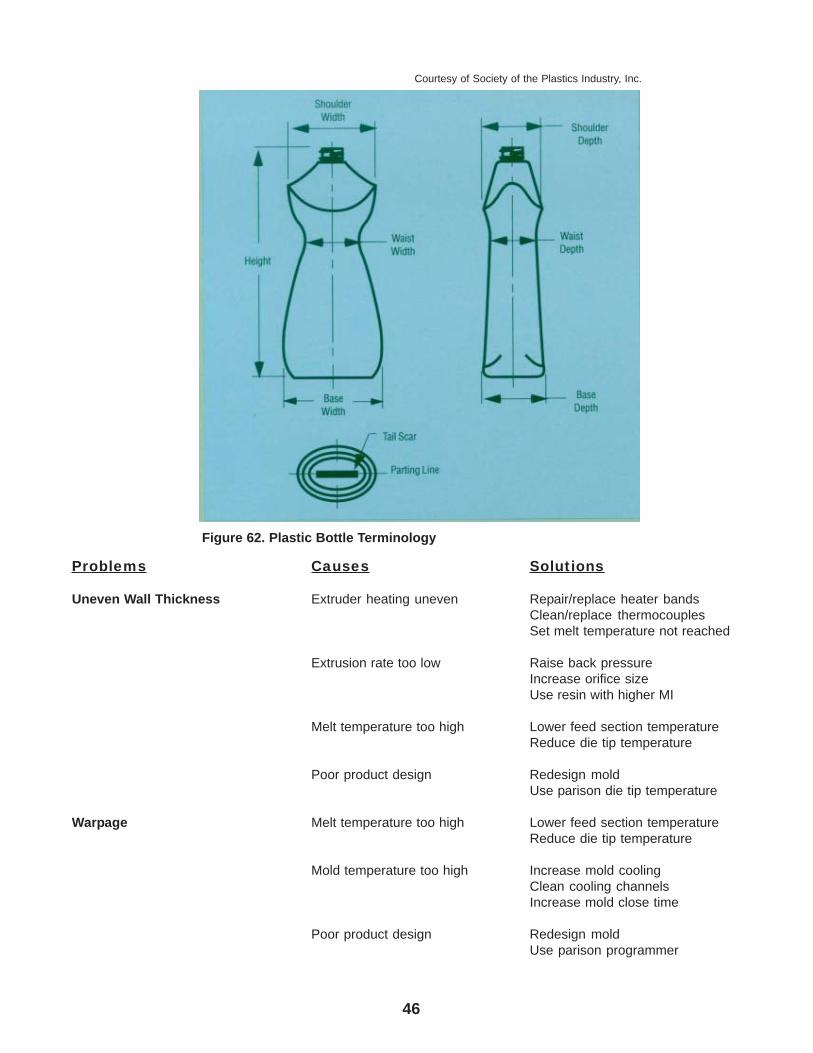
46
Problems Causes Solutions
Uneven Wall Thickness Extruder heating uneven Repair/replace heater bandsClean/replace thermocouplesSet melt temperature not reached
Extrusion rate too low Raise back pressureIncrease orifice sizeUse resin with higher MI
Melt temperature too high Lower feed section temperatureReduce die tip temperature
Poor product design Redesign moldUse parison die tip temperature
Warpage Melt temperature too high Lower feed section temperatureReduce die tip temperature
Mold temperature too high Increase mold coolingClean cooling channelsIncrease mold close time
Poor product design Redesign moldUse parison programmer
Figure 62. Plastic Bottle Terminology
Courtesy of Society of the Plastics Industry, Inc.
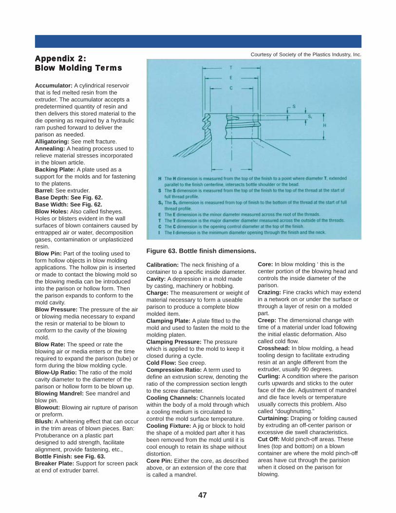
47
AAAAAppendix 2:ppendix 2:ppendix 2:ppendix 2:ppendix 2:BloBloBloBloBlow Molding w Molding w Molding w Molding w Molding TTTTTererererermsmsmsmsms
Accumulator: A cylindrical reservoirthat is fed melted resin from theextruder. The accumulator accepts apredetermined quantity of resin andthen delivers this stored material to thedie opening as required by a hydraulicram pushed forward to deliver theparison as needed.Alligatoring: See melt fracture.Annealing: A heating process used torelieve material stresses incorporatedin the blown article.Backing Plate: A plate used as asupport for the molds and for fasteningto the platens.Barrel: See extruder.Base Depth: See Fig. 62.Base Width: See Fig. 62.Blow Holes: Also called fisheyes.Holes or blisters evident in the wallsurfaces of blown containers caused byentrapped air or water, decompositiongases, contamination or unplasticizedresin.Blow Pin: Part of the tooling used toform hollow objects in blow moldingapplications. The hollow pin is insertedor made to contact the blowing mold sothe blowing media can be introducedinto the parison or hollow form. Thenthe parison expands to conform to themold cavity.Blow Pressure: The pressure of the airor blowing media necessary to expandthe resin or material to be blown toconform to the cavity of the blowingmold.Blow Rate: The speed or rate theblowing air or media enters or the timerequired to expand the parison (tube) orform during the blow molding cycle.Blow-Up Ratio: The ratio of the moldcavity diameter to the diameter of theparison or hollow form to be blown up.Blowing Mandrel: See mandrel andblow pin.Blowout: Blowing air rupture of parisonor preform.Blush: A whitening effect that can occurin the trim areas of blown pieces. Ban:Protuberance on a plastic partdesigned to add strength, facilitatealignment, provide fastening, etc.,Bottle Finish: see Fig. 63.Breaker Plate: Support for screen packat end of extruder barrel.
Calibration: The neck finishing of acontainer to a specific inside diameter.Cavity: A depression in a mold madeby casting, machinery or hobbing.Charge: The measurement or weight ofmaterial necessary to form a useableparison to produce a complete blowmolded item.Clamping Plate: A plate fitted to themold and used to fasten the mold to themolding platen.Clamping Pressure: The pressurewhich is applied to the mold to keep itclosed during a cycle.Cold Flow: See creep.Compression Ratio: A term used todefine an extrusion screw, denoting theratio of the compression section lengthto the screw diameter.Cooling Channels: Channels locatedwithin the body of a mold through whicha cooling medium is circulated tocontrol the mold surface temperature.Cooling Fixture: A jig or block to holdthe shape of a molded part after it hasbeen removed from the mold until it iscool enough to retain its shape withoutdistortion.Core Pin: Either the core, as describedabove, or an extension of the core thatis called a mandrel.
Core: In blow molding ‘ this is thecenter portion of the blowing head andcontrols the inside diameter of theparison.Crazing: Fine cracks which may extendin a network on or under the surface orthrough a layer of resin on a moldedpart.Creep: The dimensional change withtime of a material under load followingthe initial elastic deformation. Alsocalled cold flow.Crosshead: In blow molding, a headtooling design to facilitate extrudingresin at an angle different from theextruder, usually 90 degrees.Curling: A condition where the parisoncurls upwards and sticks to the outerface of the die. Adjustment of mandreland die face levels or temperatureusually corrects this problem. Alsocalled “doughnutting.”Curtaining: Draping or folding causedby extruding an off-center parison orexcessive die swell characteristics.Cut Off: Mold pinch-off areas. Theselines (top and bottom) on a blowncontainer are where the mold pinch-offareas have cut through the parisionwhen it closed on the parison forblowing.
Figure 63. Bottle finish dimensions.
Courtesy of Society of the Plastics Industry, Inc.
48
Cycle: The complete sequence ofoperations in a process to completeone set of parts. The cycle starts at apoint in the operation and ends whenthis point is again reached.Daylight Opening: The clearancebetween two mold halves or platens ofa clamping press in the open position.Deflashing: A finishing operation forremoving flash on a plastic moldingsuch as tails, handle plugs and materialaround thread areas.Delamination: The surface of thefinished part separates or appears to becomposed of layers of solidified resin.Strata or fish scale-type appearancewhere the layers may be separated.Density: Weight per unit volume of aresin usually expressed in grams percubic centimeter.Die Gap: In blow molding, the distancebetween the mandrel and die in theblowing head. This clearance governsthe thickness of the extruded parisonand thus the thickness of the walls ofthe finished part.Die Land: See Land.Die Lines: Lines that are evident in thefinished molded part caused by themeeting or remeeting of the moltenresin as it flows around the core or diepin to form the parison or extrudedtube.Die Swell Ratio: The ratio) of the outerparison diameter (or parison thickness)to the outer diameter (or die gap).Die: Any tool or arrangement of toolsdesigned to shape or form materials toa desired configuration.Dispersion Aid: The breaker plate,screen pack or other device in the meltstream that allows uniform mixing andforces the suspended materials to beuniformly dispersed in the melt stream’Dispersion: The suspension of amaterial (color) in the resin.Draft: The degree of taper of a side wallor the angle of clearance designed tofacilitate removal of parts from a mold.Ejection: In blow molding, the removalof the finished item from the mold cavityand away from the blowing area.Elongation: The increase in length of amolded piece of resin stressed intension.Extrudate Melt: The product or parisonmaterials delivered by an extruder.Extruder: The part of the blow moldingmachine in which the polyolefin resin ismelted and pushed forward toward thedie. It consists of a barrel enclosing aconstantly turning screw, heaters,thermocouples to measure melttemperature and a screen pack.
Flame Treating: See Surface treating.Flash: Excess plastic attached to themolded item that is formed by thepinchoff areas of the mold as it closeson the parison.Flow Line: Visible marks on thefinished item that indicate where themelt has joined or remet in the die headas it flowed around the core or mandrelto form the parison; also called weldline, flow line and die line.Flow: A qualitative description of thefluidity of a plastic material during theprocess of molding. A measure of itsprocessability.Gear Pumps: See Melt pumps. Gel: Inpolyethylene, a small amorphousparticle which differs from othersbecause of its high molecular weightand/or crosslinking. Its processingcharacteristics are different and moredifficult to homogenize into the resinmelt.Gloss: The shine or luster of thesurface of a finished object.Gravimetric Feeders: Feeders thatmeasure the weight of materials fed tothe extruder from a special weighhopper and determine the rate at whichthe material is consumed.Grit Blasted: See Sand blasting.Guide Pins: Pins in the face of themold to assure proper alignment whenthey are closed.Handleware: Containers with handles.Head: In blow molding, the end sectionof the molding machine that consists ofthe core, die, mandrel and other partsnecessary to form the resin into ahollow tube (parison) with the correctdimensions and thickness. The headdelivers this parison to the area where itcan be picked up and transferred to theblowing mold.Heel: The part of a container betweenthe bottom bearing surface and the sidewall.High-Load Melt Index: Thedesignation commonly used for highmolecular weight resins, a measure ofthe resin’s ability to flow through anorifice of a melt indexer with a heavierweight applying the pressure (21,600gram weight). See also Melt Index.Impact Resistance: The susceptibilityof a resin or object molded from a resinto fracture by shock such as dropping.Injection ram: The ram or screw whichapplies pressure to the molten resin toforce it through the tooling.
Injection Stretch Blow Molding:Process in which hot preforms arestretched before being blow molded.Stretching improves clarity and sidewall stiffness.Insert: An integral part of a plasticmolding consisting of plastic, metal orother materials that has beenpreformed and inserted into the blowingmold so it becomes an integral part ofthe finished item. Jig: See Coolingfixture.Knit Lines: See Flow Lines.L/D Ratio: A term used to define anextrusion screw, denoting the ratio ofthe screw length to the screw diameter.Land: The bearing surface along thetop of the flights of a screw; also theworking area near the tooling openingof a die and mandrel that maintains aconstant or controlled volume of resinprior to its leaving the tooling in theform of a parison. Also called die land.Lightweighting: Design process toreduce weight of containers.Lubricant: Additive to resin designed tofacilitate part removal from mold cavity.Mandrel: The central portion or “core”of the tooling at the opening where theparison is formed.Manifold: The configuration of pipingthat takes a single channel flow of resinfrom an extruder and divides it intovarious flow channels to feed morethan one head or one head in morethan one place.Melt Flow Rate: An indication of thefluidity of polypropylene resins. It is ameasure of the amount of material thatcan be forced through a given orificewhen subjected to a given weight in agiven time. See ASTM D 1238-65T forfurther information.Melt Fracture: Also called alligatoring,sharkskin or herringbone. This is ashearing effect or instability in the meltflow through a die clearance. Thisinstability of flow causes irregular roughsurfaces on the finished container.Adjustment of tooling, heat, extrusionrate or improved resin flow is requiredto correct this problem.Melt Index: An indication of the fluidityof polyethylene resins. It is a measureof the amount of material that can beforced through a given orifice whensubjected to a given weight in a giventime. See ASTM D 1238-65T for furtherinformation.Melt Pumps: Units at end of barrel andbefore the die head that greatlyincrease melt quality, by eliminating anysurging resulting from the screw action.
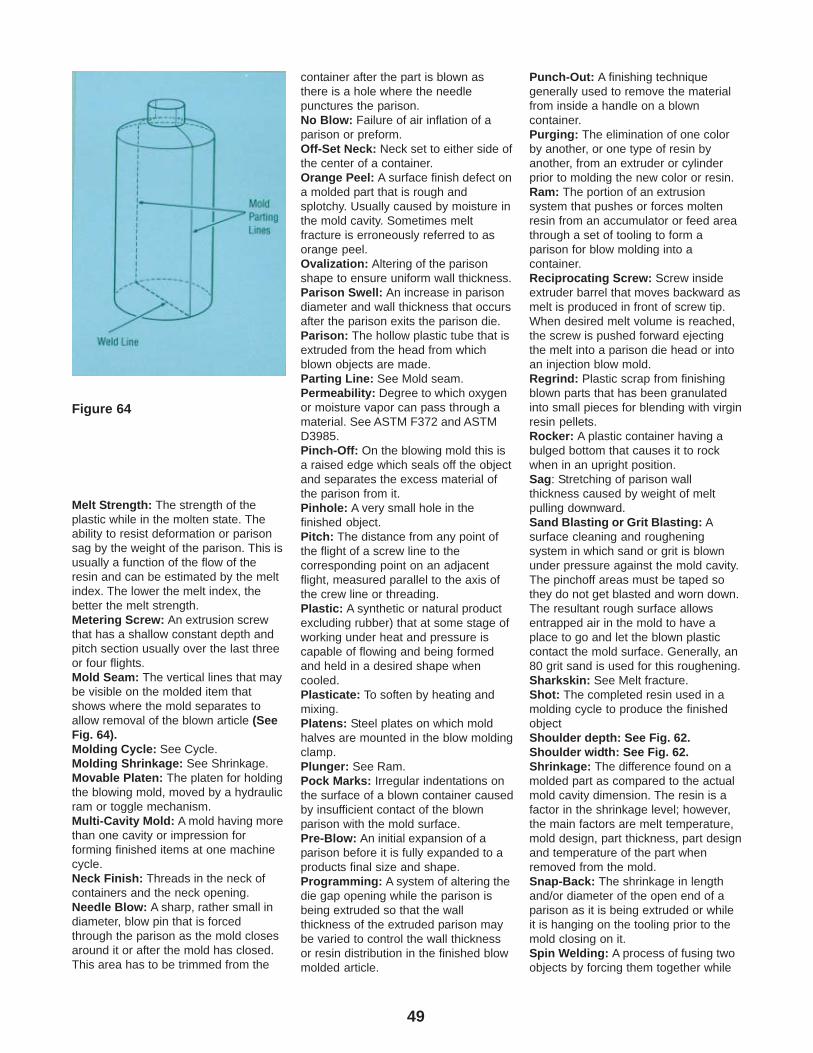
49
Melt Strength: The strength of theplastic while in the molten state. Theability to resist deformation or parisonsag by the weight of the parison. This isusually a function of the flow of theresin and can be estimated by the meltindex. The lower the melt index, thebetter the melt strength.Metering Screw: An extrusion screwthat has a shallow constant depth andpitch section usually over the last threeor four flights.Mold Seam: The vertical lines that maybe visible on the molded item thatshows where the mold separates toallow removal of the blown article (SeeFig. 64).Molding Cycle: See Cycle.Molding Shrinkage: See Shrinkage.Movable Platen: The platen for holdingthe blowing mold, moved by a hydraulicram or toggle mechanism.Multi-Cavity Mold: A mold having morethan one cavity or impression forforming finished items at one machinecycle.Neck Finish: Threads in the neck ofcontainers and the neck opening.Needle Blow: A sharp, rather small indiameter, blow pin that is forcedthrough the parison as the mold closesaround it or after the mold has closed.This area has to be trimmed from the
container after the part is blown asthere is a hole where the needlepunctures the parison.No Blow: Failure of air inflation of aparison or preform.Off-Set Neck: Neck set to either side ofthe center of a container.Orange Peel: A surface finish defect ona molded part that is rough andsplotchy. Usually caused by moisture inthe mold cavity. Sometimes meltfracture is erroneously referred to asorange peel.Ovalization: Altering of the parisonshape to ensure uniform wall thickness.Parison Swell: An increase in parisondiameter and wall thickness that occursafter the parison exits the parison die.Parison: The hollow plastic tube that isextruded from the head from whichblown objects are made.Parting Line: See Mold seam.Permeability: Degree to which oxygenor moisture vapor can pass through amaterial. See ASTM F372 and ASTMD3985.Pinch-Off: On the blowing mold this isa raised edge which seals off the objectand separates the excess material ofthe parison from it.Pinhole: A very small hole in thefinished object.Pitch: The distance from any point ofthe flight of a screw line to thecorresponding point on an adjacentflight, measured parallel to the axis ofthe crew line or threading.Plastic: A synthetic or natural productexcluding rubber) that at some stage ofworking under heat and pressure iscapable of flowing and being formedand held in a desired shape whencooled.Plasticate: To soften by heating andmixing.Platens: Steel plates on which moldhalves are mounted in the blow moldingclamp.Plunger: See Ram.Pock Marks: Irregular indentations onthe surface of a blown container causedby insufficient contact of the blownparison with the mold surface.Pre-Blow: An initial expansion of aparison before it is fully expanded to aproducts final size and shape.Programming: A system of altering thedie gap opening while the parison isbeing extruded so that the wallthickness of the extruded parison maybe varied to control the wall thicknessor resin distribution in the finished blowmolded article.
Punch-Out: A finishing techniquegenerally used to remove the materialfrom inside a handle on a blowncontainer.Purging: The elimination of one colorby another, or one type of resin byanother, from an extruder or cylinderprior to molding the new color or resin.Ram: The portion of an extrusionsystem that pushes or forces moltenresin from an accumulator or feed areathrough a set of tooling to form aparison for blow molding into acontainer.Reciprocating Screw: Screw insideextruder barrel that moves backward asmelt is produced in front of screw tip.When desired melt volume is reached,the screw is pushed forward ejectingthe melt into a parison die head or intoan injection blow mold.Regrind: Plastic scrap from finishingblown parts that has been granulatedinto small pieces for blending with virginresin pellets.Rocker: A plastic container having abulged bottom that causes it to rockwhen in an upright position.Sag: Stretching of parison wallthickness caused by weight of meltpulling downward.Sand Blasting or Grit Blasting: Asurface cleaning and rougheningsystem in which sand or grit is blownunder pressure against the mold cavity.The pinchoff areas must be taped sothey do not get blasted and worn down.The resultant rough surface allowsentrapped air in the mold to have aplace to go and let the blown plasticcontact the mold surface. Generally, an80 grit sand is used for this roughening.Sharkskin: See Melt fracture.Shot: The completed resin used in amolding cycle to produce the finishedobjectShoulder depth: See Fig. 62.Shoulder width: See Fig. 62.Shrinkage: The difference found on amolded part as compared to the actualmold cavity dimension. The resin is afactor in the shrinkage level; however,the main factors are melt temperature,mold design, part thickness, part designand temperature of the part whenremoved from the mold.Snap-Back: The shrinkage in lengthand/or diameter of the open end of aparison as it is being extruded or whileit is hanging on the tooling prior to themold closing on it.Spin Welding: A process of fusing twoobjects by forcing them together while
Figure 64
50
one of the two is spinning until frictionalheat melts the interface.Stress Cracking: The phenomenoncausing plastic material to fail after ithas been processed into finishedobjects and placed in contact withcertain chemical reagents. Normally,the finished objects are stressed duringproduction or are under stress duringuse. When these stressed parts areplaced in contact with a wetting agent,they tend to fail.Stripper: A plate or ejection device thatremoves the finished molded part fromthe tooling or mold at the end of thecycle.Suck-Back: See Snap-back.Surface Treating: A system of treatingthe surface of the finished container soit accepts ink, lacquers, paints,adhesives, etc. This treating is usuallydone by an oxidizing flame. However,electronic treating by a “corona”discharge or a chemical treatment inhot dichromate and sulfuric acid maybe used to accomplish the same task.Swell: Expansion of parison as its exitsthe parison die.Tail Scar: See Fig. 62.Tensile Strength: The pulling stress inpsi required to break a given specimen.Throughput: Amount of melt that canbe processed by a plasticating unit inan hour, e.g. XX lbs./hr. Also thenumber of blown products that can bemade in an hour, e,g., XX 8-oz. bottles/hr.Toggle: A mechanism that exertspressure developed by applying forceon a knee joint. It is used to close andexert pressure on a molding press.Undercut: Having a protuberance orindentation that impedes withdrawalfrom a two-piece rigid mold.Vent: A shallow channel or opening cutin the cavity to allow air or gases toescape from the mold as the parison isexpanded to fill the cavity.Viscosity: Internal friction or resistanceto flow of a liquid. The constant ratio ofshearing stress to rate of shear. Inliquids for which this ratio is a functionof stress, the term “apparent viscosity”is defined as this ratio.Volumetric Feeders: Units that feedresin based on the volume of resinneeded to fill the hopper.Waist Depth: See Fig. 62.Waist Width: See Fig. 62.Warpage: Dimensional distortion in amolded object.Weld Line: See Fig. 64.
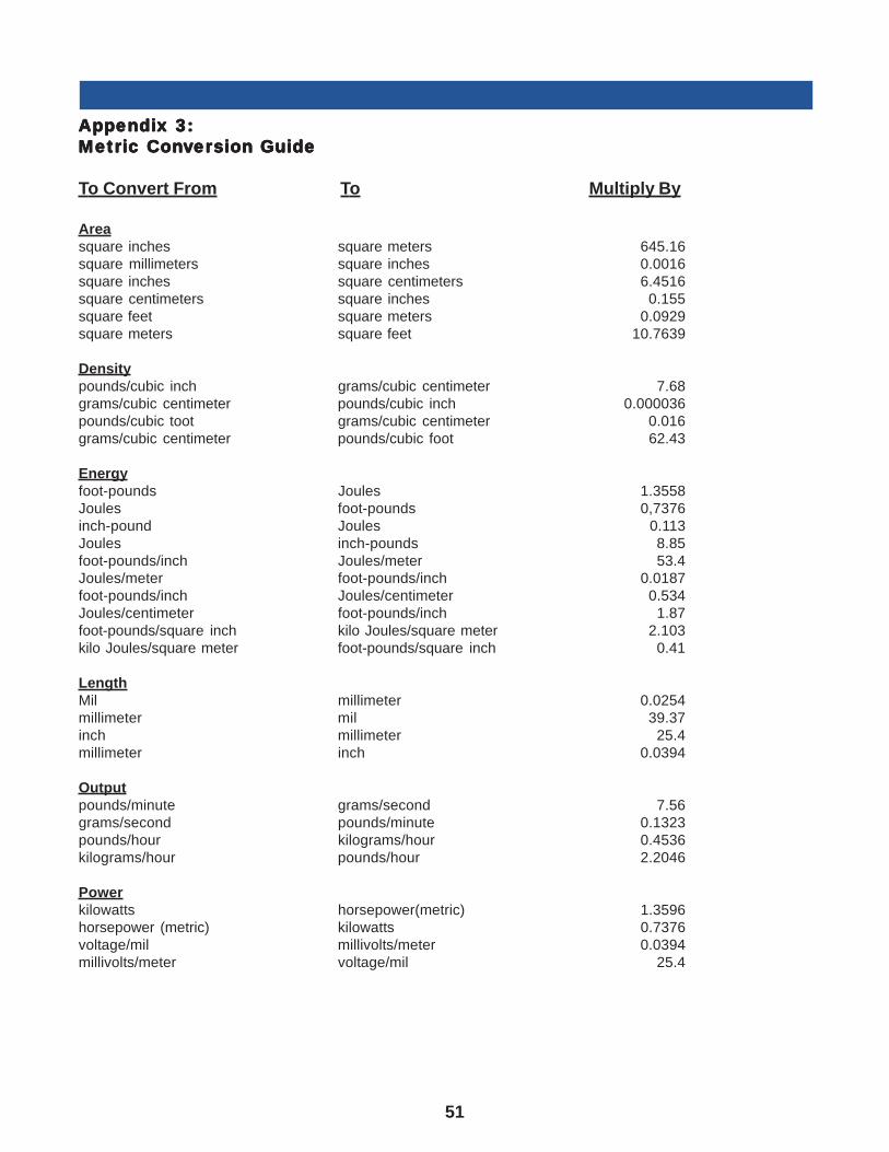
51
AAAAAppendix 3:ppendix 3:ppendix 3:ppendix 3:ppendix 3:Metric ConMetric ConMetric ConMetric ConMetric Convvvvvererererersion Guidesion Guidesion Guidesion Guidesion Guide
To Convert From To Multiply By
Areasquare inches square meters 645.16square millimeters square inches 0.0016square inches square centimeters 6.4516square centimeters square inches 0.155square feet square meters 0.0929square meters square feet 10.7639
Densitypounds/cubic inch grams/cubic centimeter 7.68grams/cubic centimeter pounds/cubic inch 0.000036pounds/cubic toot grams/cubic centimeter 0.016grams/cubic centimeter pounds/cubic foot 62.43
Energyfoot-pounds Joules 1.3558Joules foot-pounds 0,7376inch-pound Joules 0.113Joules inch-pounds 8.85foot-pounds/inch Joules/meter 53.4Joules/meter foot-pounds/inch 0.0187foot-pounds/inch Joules/centimeter 0.534Joules/centimeter foot-pounds/inch 1.87foot-pounds/square inch kilo Joules/square meter 2.103kilo Joules/square meter foot-pounds/square inch 0.41
LengthMil millimeter 0.0254millimeter mil 39.37inch millimeter 25.4millimeter inch 0.0394
Outputpounds/minute grams/second 7.56grams/second pounds/minute 0.1323pounds/hour kilograms/hour 0.4536kilograms/hour pounds/hour 2.2046
Powerkilowatts horsepower(metric) 1.3596horsepower (metric) kilowatts 0.7376voltage/mil millivolts/meter 0.0394millivolts/meter voltage/mil 25.4
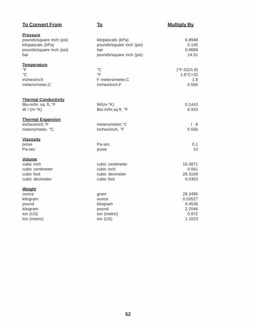
52
To Convert From To Multiply By
Pressurepounds/square inch (psi) kilopascals (kPa) 6.8948kilopascals (kPa) pounds/square inch (psi) 0.145pounds/square inch (psi) bar 0.0689bar pounds/square inch (psi) 14.51
Temperature°F °C (°F-32)/1.8)°C °F 1.8°C+32inches/inch F meters/meter,C 1.8meters/meter,C inches/inch,F 0.556
Thermal ConductivityBtu-in/hr, sq. ft.,°F W/(m-°K) 0.1442W / (m-°K) Btu-in/hr,sq ft, °F 6.933
Thermal Expansioninches/inch,°F meters/meter,°C I . 8meters/meter, °C inches/inch, °F 0.556
Viscositypoise Pa-sec. 0.1Pa-sec poise 10
Volumecubic inch cubic centimeter 16.3871cubic centimeter cubic inch 0.061cubic foot cubic decimeter 28.3169cubic decimeter cubic foot 0.0353
Weightounce gram 28.3495kilogram ounce 0.03527pound kilogram 0.4536kilogram pound 2.2046ton (US) ton (metric) 0.972ton (metric) ton (US) 1.1023
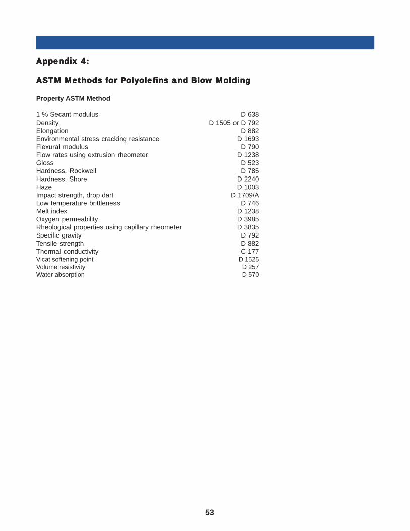
53
AAAAAppendix 4:ppendix 4:ppendix 4:ppendix 4:ppendix 4:
ASTM Methods fASTM Methods fASTM Methods fASTM Methods fASTM Methods for Por Por Por Por Polololololyyyyyolefolefolefolefolefins and Bloins and Bloins and Bloins and Bloins and Blow Moldingw Moldingw Moldingw Moldingw Molding
Property ASTM Method
1 % Secant modulus D 638Density D 1505 or D 792Elongation D 882Environmental stress cracking resistance D 1693Flexural modulus D 790Flow rates using extrusion rheometer D 1238Gloss D 523Hardness, Rockwell D 785Hardness, Shore D 2240Haze D 1003Impact strength, drop dart D 1709/ALow temperature brittleness D 746Melt index D 1238Oxygen permeability D 3985Rheological properties using capillary rheometer D 3835Specific gravity D 792Tensile strength D 882Thermal conductivity C 177Vicat softening point D 1525Volume resistivity D 257Water absorption D 570
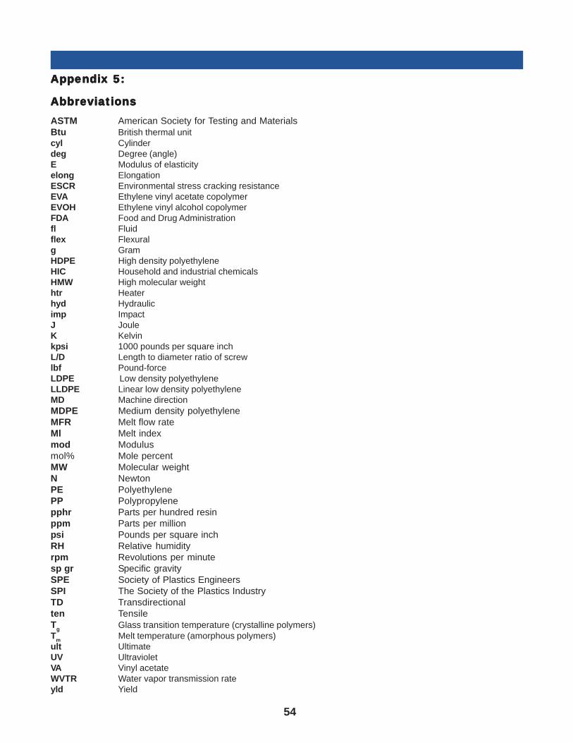
54
AAAAAppendix 5:ppendix 5:ppendix 5:ppendix 5:ppendix 5:
AbAbAbAbAbbrbrbrbrbreeeeeviaviaviaviaviationstionstionstionstionsASTM American Society for Testing and MaterialsBtu British thermal unitcyl Cylinderdeg Degree (angle)E Modulus of elasticityelong ElongationESCR Environmental stress cracking resistanceEVA Ethylene vinyl acetate copolymerEVOH Ethylene vinyl alcohol copolymerFDA Food and Drug Administrationfl Fluidflex Flexuralg GramHDPE High density polyethyleneHIC Household and industrial chemicalsHMW High molecular weighthtr Heaterhyd Hydraulicimp ImpactJ JouleK Kelvinkpsi 1000 pounds per square inchL/D Length to diameter ratio of screwlbf Pound-forceLDPE Low density polyethyleneLLDPE Linear low density polyethyleneMD Machine directionMDPE Medium density polyethyleneMFR Melt flow rateMl Melt indexmod Modulusmol% Mole percentMW Molecular weightN NewtonPE PolyethylenePP Polypropylenepphr Parts per hundred resinppm Parts per millionpsi Pounds per square inchRH Relative humidityrpm Revolutions per minutesp gr Specific gravitySPE Society of Plastics EngineersSPI The Society of the Plastics IndustryTD Transdirectionalten TensileT
gGlass transition temperature (crystalline polymers)
Tm
Melt temperature (amorphous polymers)ult UltimateUV UltravioletVA Vinyl acetateWVTR Water vapor transmission rateyld Yield
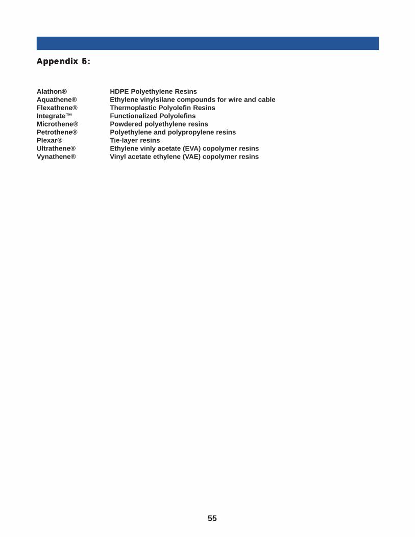
55
AAAAAppendix 5:ppendix 5:ppendix 5:ppendix 5:ppendix 5
Alathon® HDPE Polyethylene ResinsAquathene® Ethylene vinylsilane compounds for wire and cableFlexathene® Thermoplastic Polyolefin ResinsIntegrate™ Functionalized PolyolefinsMicrothene® Powdered polyethylene resinsPetrothene® Polyethylene and polypropylene resinsPlexar® Tie-layer resinsUltrathene® Ethylene vinly acetate (EVA) copolymer resinsVynathene® Vinyl acetate ethylene (VAE) copolymer resins

6683/0715
LyondellBasell IndustriesP.O. Box 3646Houston, TX 77252-3646United States
www.LYB.com
Before using a product sold by a company of the LyondellBasell family of companies, users should make their own independent determination that the product is suitable for the intended use and can be used safely and legally. SELLER MAKES NO WARRANTY; EXPRESS OR IMPLIED (INCLUDING ANY WARRANTY OF MERCHANTABILITY OR FITNESS FOR A PARTICULAR PURPOSE OR ANY WARRANTY) OTHER THAN AS SEPARATELY AGREED TO BY THE PARTIES IN A CONTRACT.LyondellBasell prohibits or restricts the use of its products in certain applications. For further information on restrictions or prohibitions of use, please contact a LyondellBasell representative.
Users should review the applicable Safety Data Sheet before handling the product.
Adflex, Adstif, Adsyl, Akoafloor, Akoalit, Alathon, Alkylate, Amazing Chemistry, Aquamarine, Aquathene, Arcopure, Arctic Plus, Arctic Shield, Avant, Catalloy, Clyrell, CRP, Crystex, Dexflex, Duopac, Duoprime, Explore & Experiment, Filmex, Flexathene, Glacido, Hifax, Hiflex, Histif, Hostacom, Hostalen, Ideal, Integrate, Koattro, LIPP, Lucalen, Luflexen, Lupolen, Lupolex, Luposim, Lupostress, Lupotech, Metocene, Microthene, Moplen, MPDIOL, Nerolex, Nexprene, Petrothene, Plexar, Polymeg, Pristene, Prodflex, Pro-Fax, Punctilious, Purell, SAA100, SAA101, Sequel, Softell, Spherilene, Spheripol, Spherizone, Starflex, Stretchene, Superflex, TBAc , Tebol, T-Hydro, Toppyl, Trans4m, Tufflo, Ultrathene, Vacido and Valtec are trademarks owned or used by the LyondellBasell family of companies.
Adsyl, Akoafloor, Akoalit, Alathon, Aquamarine, Arcopure, Arctic Plus, Arctic Shield, Avant, CRP, Crystex, Dexflex, Duopac, Duoprime, Explore & Experiment, Filmex, Flexathene, Hifax, Hostacom, Hostalen, Ideal, Integrate, Koattro, Lucalen, Lupolen, Metocene, Microthene, Moplen, MPDIOL, Nexprene, Petrothene, Plexar, Polymeg, Pristene, Pro-Fax, Punctilious, Purell, Sequel, Softell, Spheripol, Spherizone, Starflex, Tebol, T-Hydro, Toppyl, Tufflo and Ultrathene are registered in the U.S. Patent and Trademark Office.
T-Hydro, Toppyl, Tufflo and Ultrathene are registered in the U.S. Patent and Trademark Office.