Embed Size (px)
Citation preview
ZENITH CONSULTANTS
38 Dryden road Loanhead Midlothian EH20 9LZ
A Guide to Non Destructive
Testing of Guy Wires
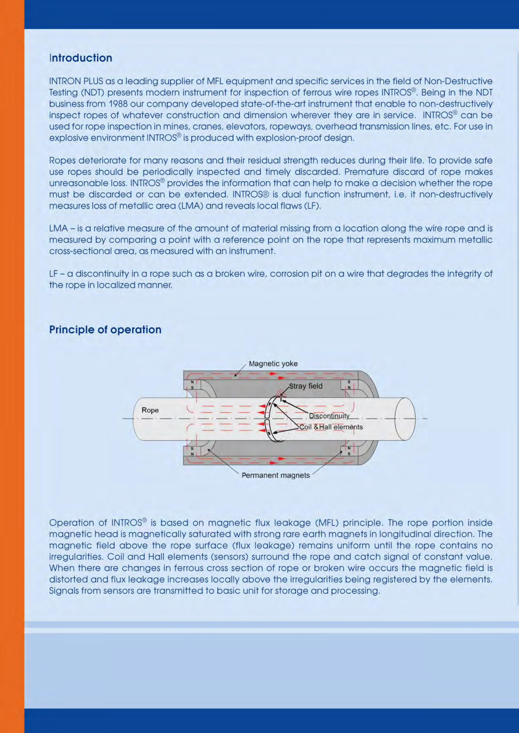
Introduction:
Zenith Structural Access Solutions offers magnetic, non-destructive testing of guy wires as part of our comprehensive range of flare stack inspections.
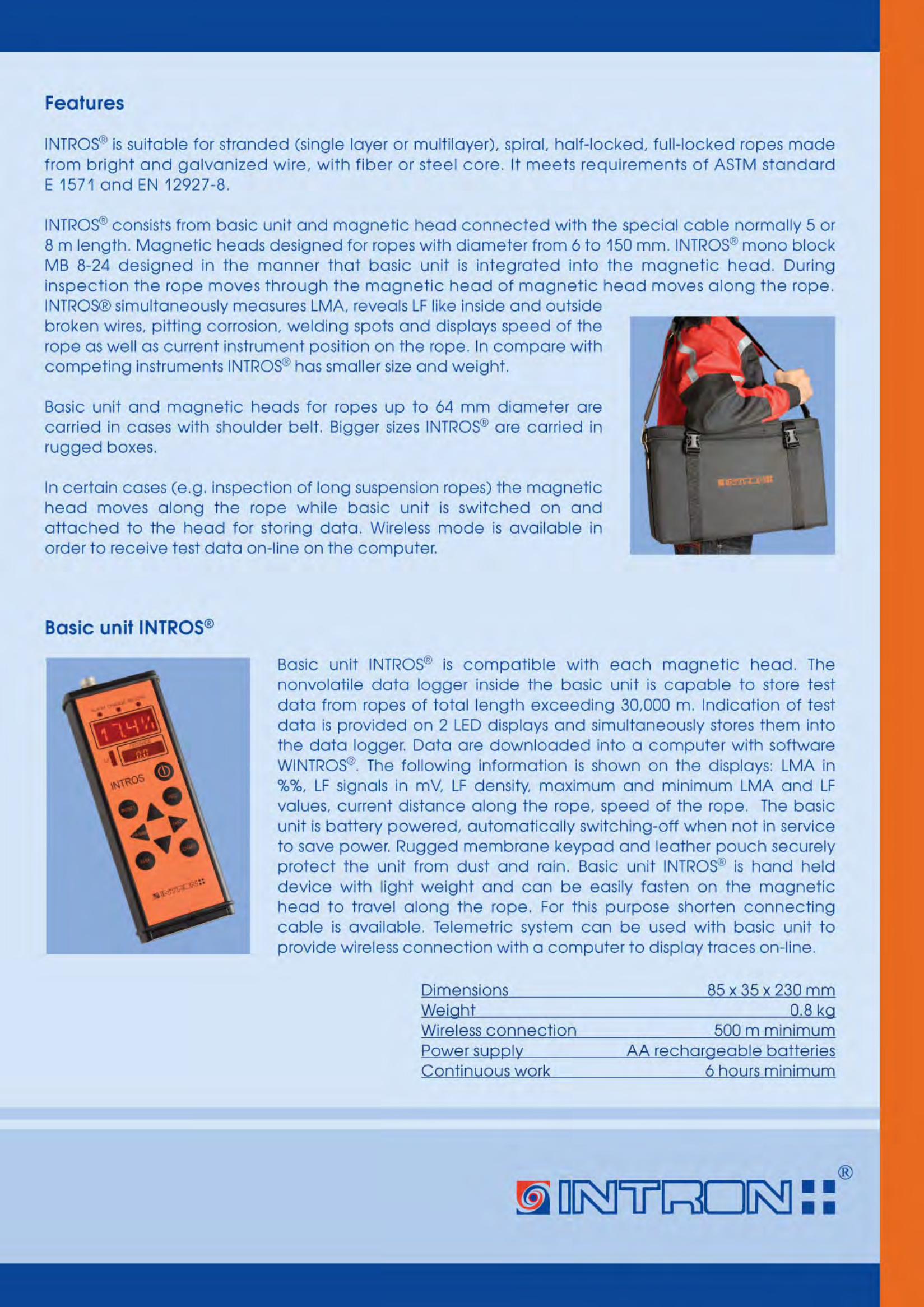
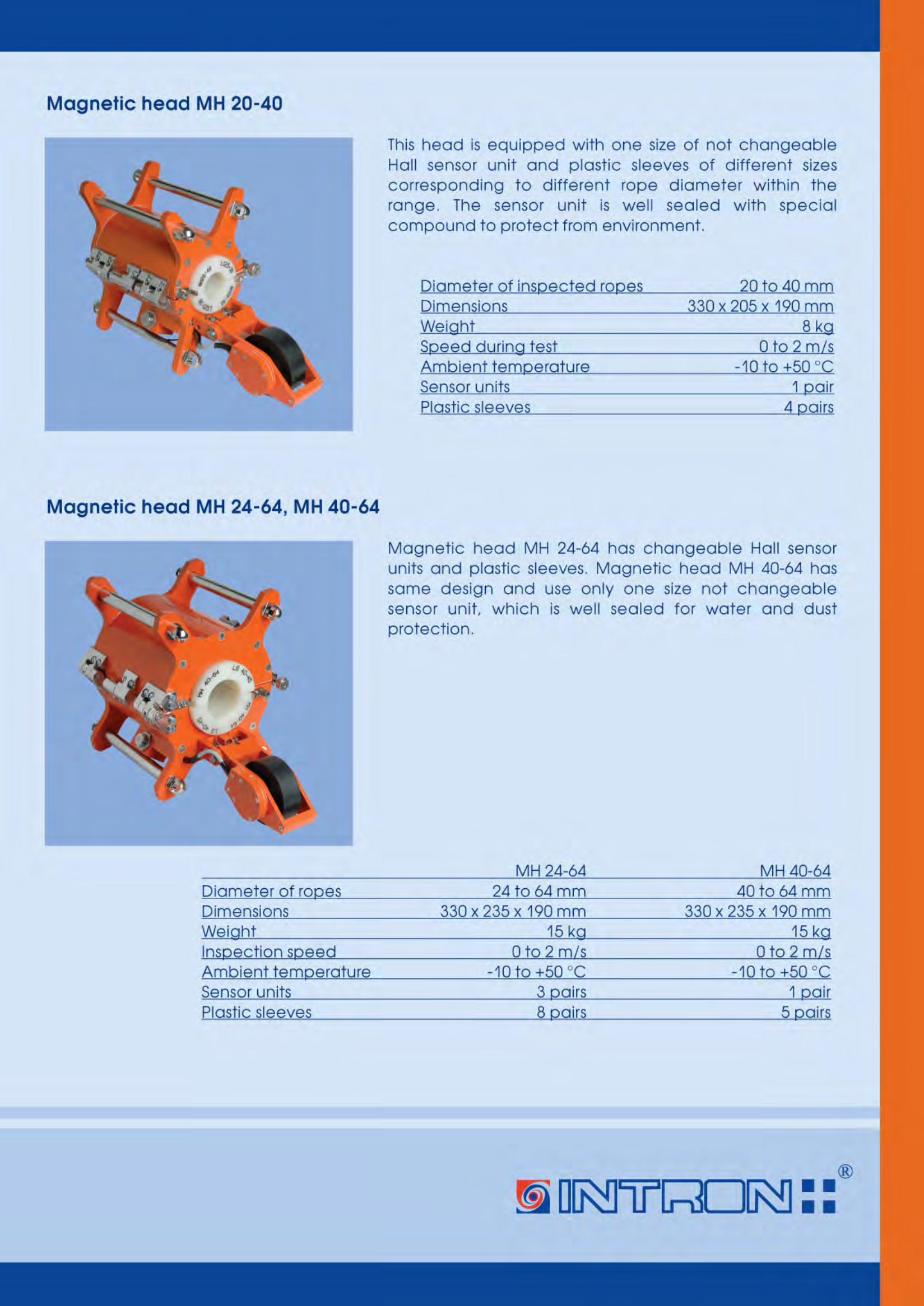
About the instrument:
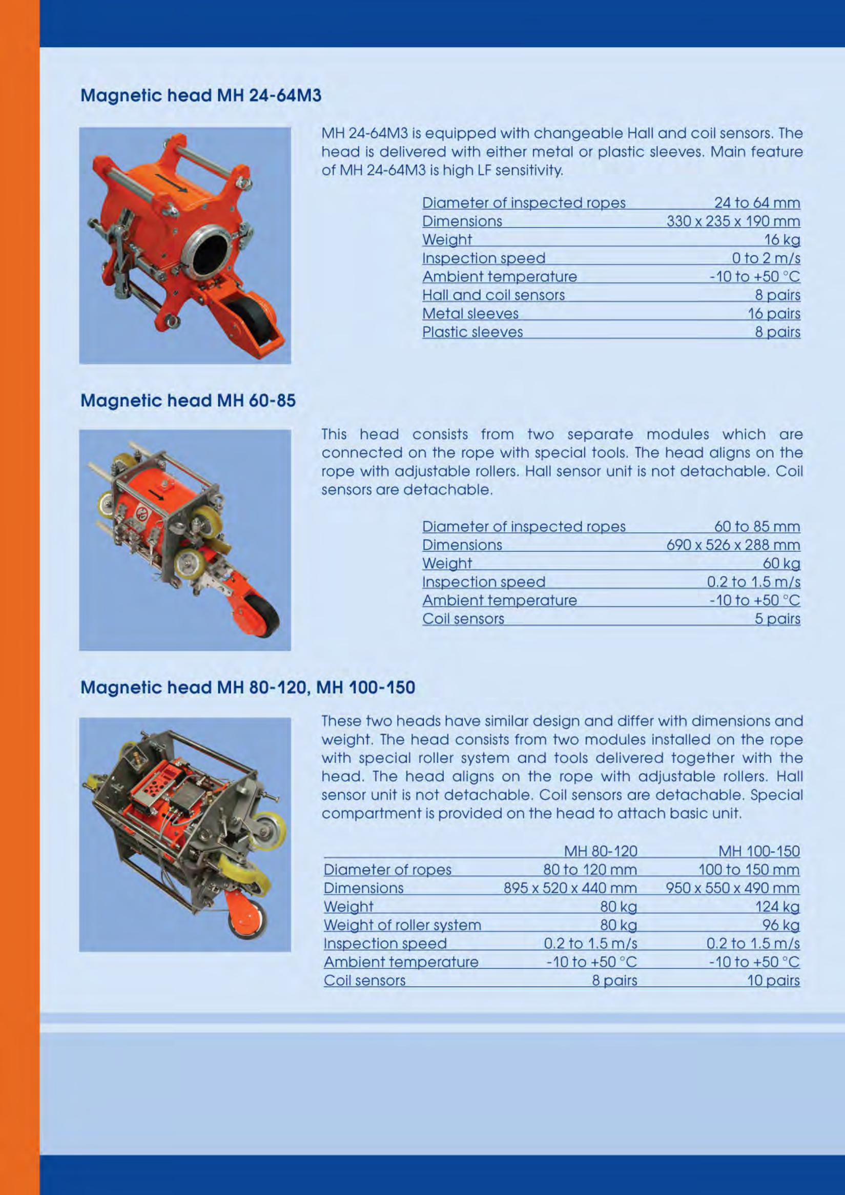
The instrument used to carry out this survey is an Intron Intros MH20-40 magnetic head. This can successfully determine faults within wires ranging from 20 and 40mm in diameter which would ordinarily go undetected by a visual inspection. The head is connected to a data logger, which records the data in real time.
For manufacturers details, see Appendix iii.
Rigging the Instrument:
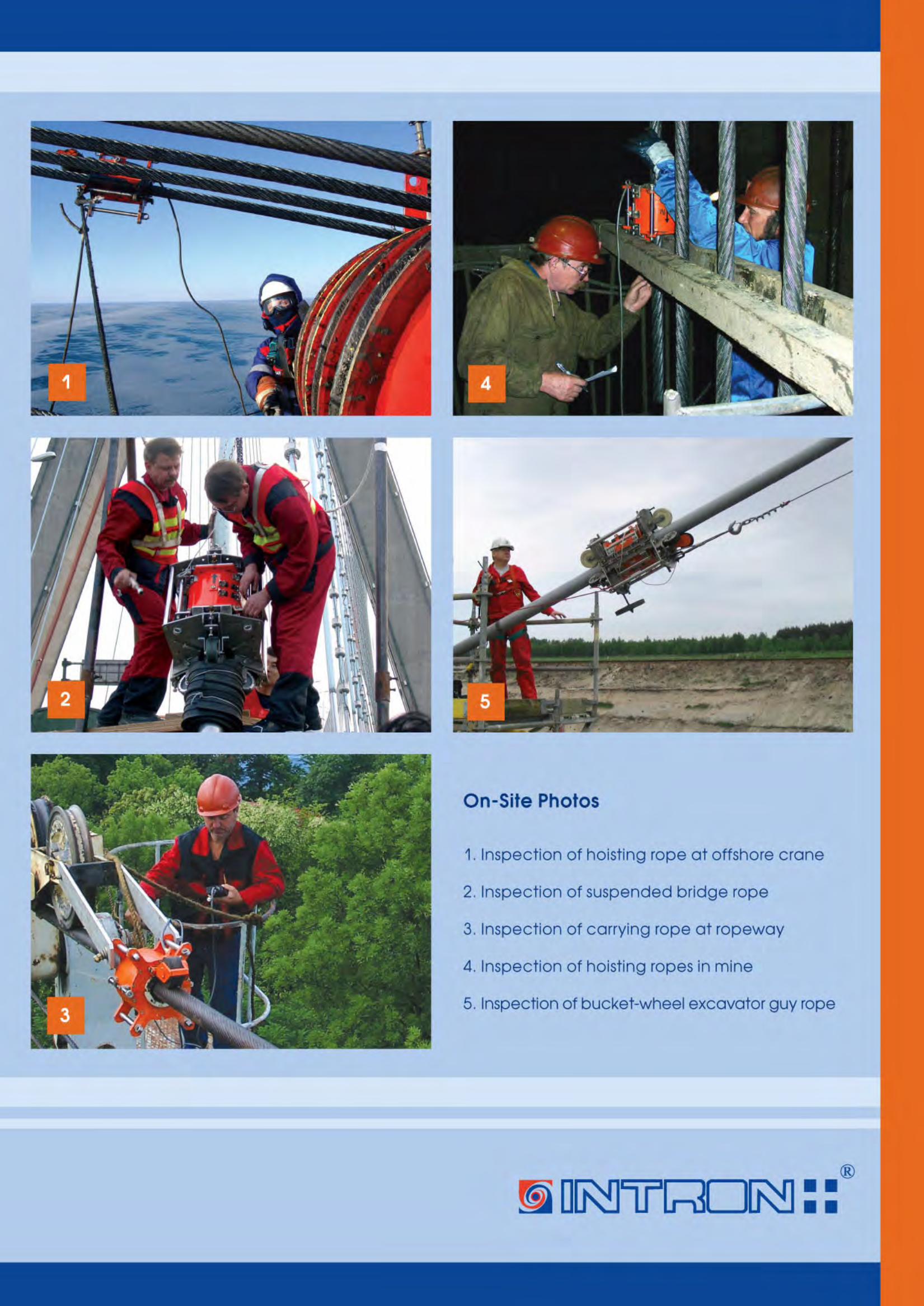
The instrument is simply clamped to the wire and pulled up and down the guy wire in a controlled manner via a pulley system mounted at the upper support. No proprietary work is required to the guy wire, and no adverse stresses or strains are imposed onto it.
How it’s done:
The survey involves attaching the magnetic head onto the wire, and running it up and down the wire to magnetise it. Once the wire is magnetised, the magnetic head is run up and down a further time to gather the required data, which is stored onto the data logger.
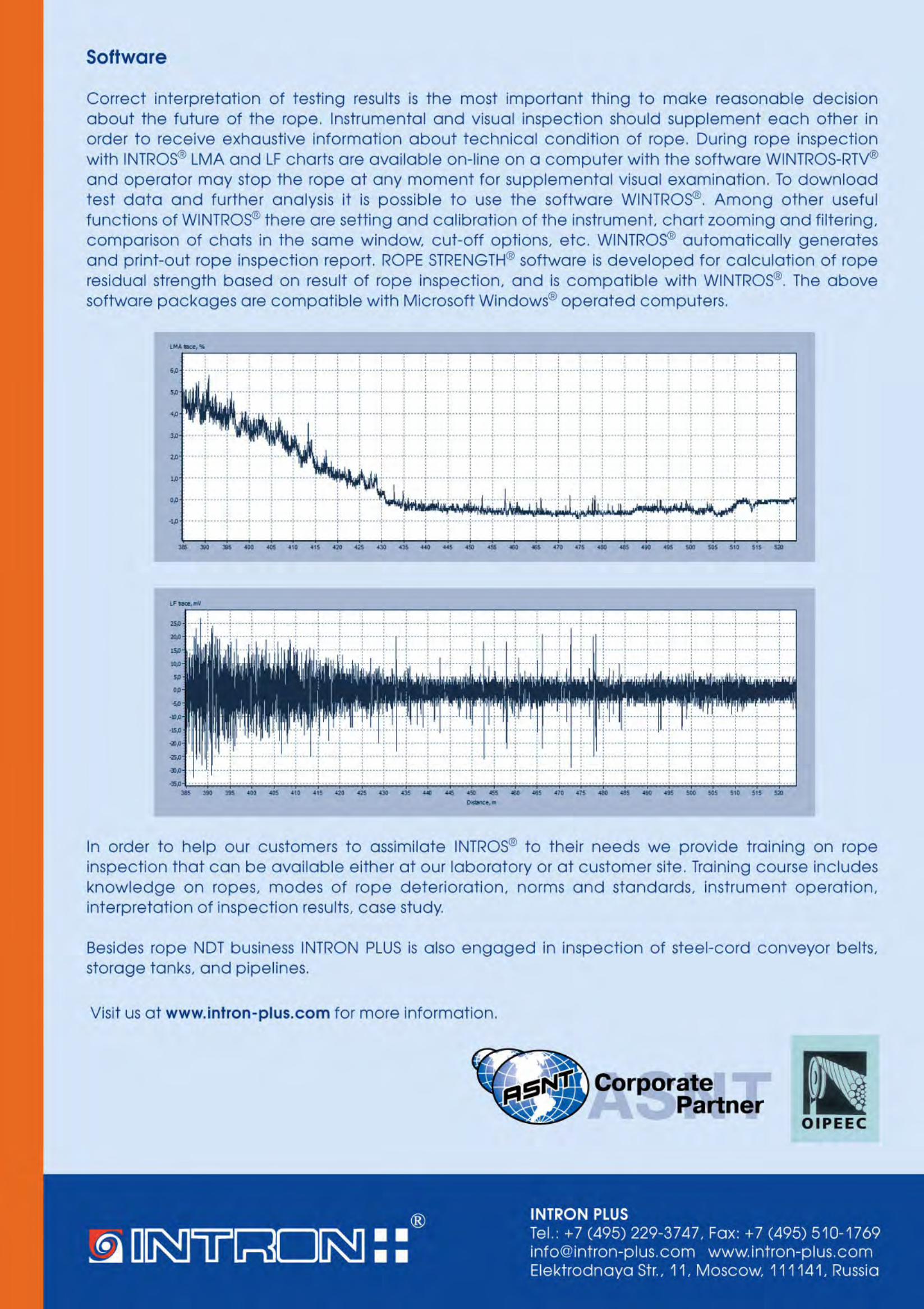
The stored information is then downloaded, and analysed using wintros software. By analysing the graphical output from the wintros software, localised faults (LF) and/or metallic loss of area (LMA) can be identified.
For full instructions, see appendix ii.
What it tells us:
These inspections aim to locate the LF’s and LMA’s, and to determine their severity / magnitude.
LF (localised fault): Detects the presence of a broken/defective wire(s), or discontinuity in the rope.
LMA (loss of metallic area): Detects loss of sectional area, highlighting possible loss of capacity.
What is produced:
A detailed report showing the likely locations and suggested severity of faults along the length of each wire.
For sample report, see Appendix i.

Appendices:
i – Sample Report
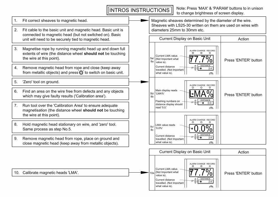
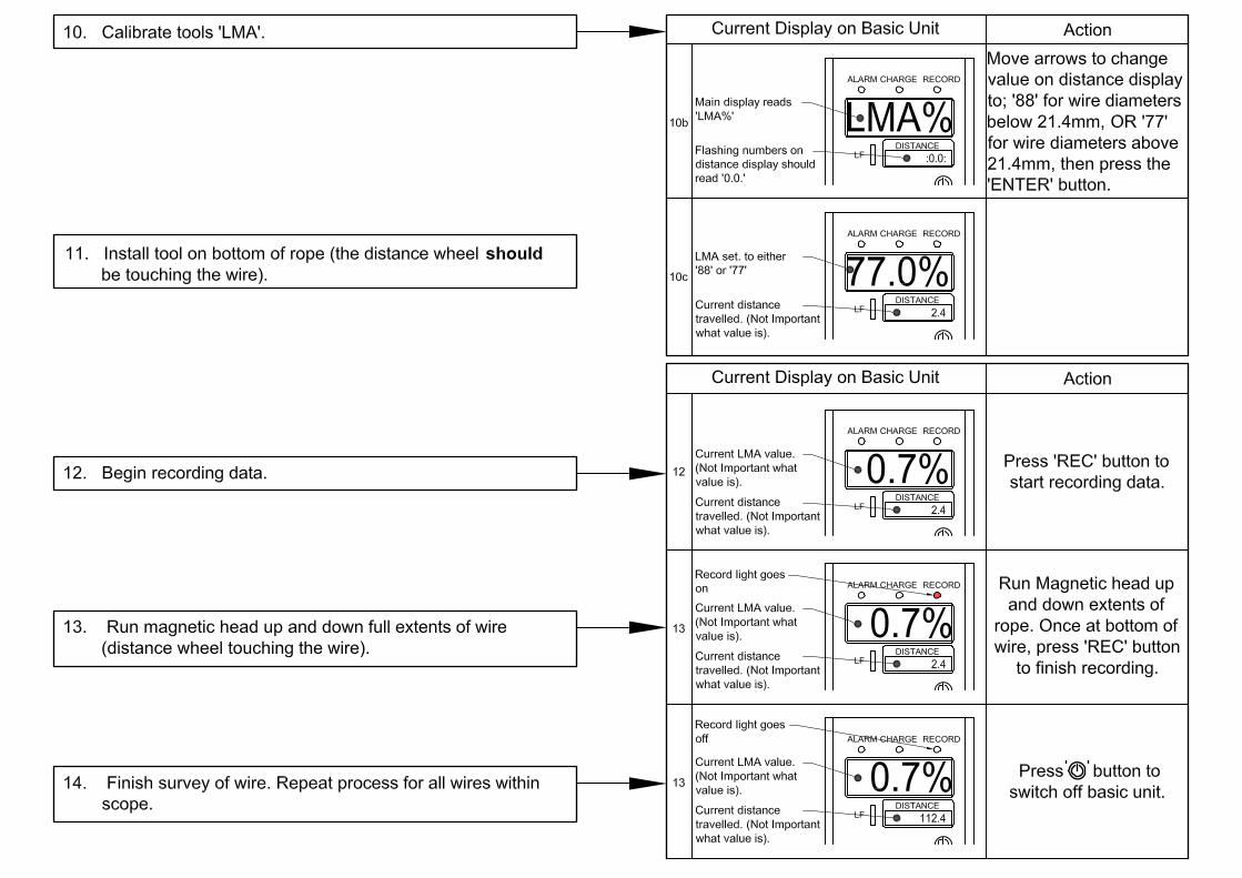
ii – Instructions for Use
iii – Manufacturers Brochure

Appendix i- Sample Report
RevC
Unit
v Details Add com
7 Dryden
e
Survey
Prepare
mparison Ta
ZENIT
Vale BilstMidl
enquiries@
XXXXXXX
Engineer…
ed By: ......
Docume
ables
TH CONSU
ton Glen Iothian EH@zenithst
XXXXXX
XX InspecRevision
……………
.................
August 20
ent RevisioDated13/10
ULTANTS
ndustrial H20 9HN tructural.c
X
ction Repon C
……………D
................J
014
on StatusStatusC
Estate Lo
com
ort
David Kelly
John Lamb
s AuthoCC
oanhead
y
b
or CheSC
cked
SECTION 1 - INTRODUCTION
1.0 INTRODUCTION
1.1 In August 2014 Zenith Consultants were engaged by XXXXXX to
undertake a survey of the 36-S500B flare stack. The survey was carried out on 03rd & 04th August 2014 during the KG TAR shutdown.The report is best read in conjunction with Appendix ‘A’, ‘B’ & ‘C’
1.2 The purpose of the survey was to identify and record any defects to
the guy wires and termination connections to the flare and to make recommendations for future repair.
SECTION 2 – DESCRIPTION OF STRUCTURE
2.0 DESCRIPTION
2.1 The flare is 90m high from ground level guyed structure, with 3No anchor blocks located at 120 degrees. Each anchor block has four guy wires supporting the flare.
2.2 The flare has a fixed ladder and staged gantries over the
height.
SECTION 3 - PROCEDURES AND METHODS
3.0 PROCEDURES AND METHODS
3.1 Access to the head of the flare was achieved using the fixed ladder/gantry arrangement.
3.2 A visual examination of all external parts.
3.3 The Magnetic Inspection was carried out on each guy wire.
3.4 The inspection was carried out using an Intron Magnetic head 20-
40 with Wintros software for assessment of the results. The apparatus uses LMA (loss of metallic area) and LF (local fault) readings to assess the condition of the cable.
3.5 The first section of cable was first magnetised and then used to
calibrate the equipment.
3,6 The inspection was carried out using a hoisting arrangement. 3.7 The cable was first magnetised before two inspections were
carried out.
SECTION 4 - SURVEY RESULTS
4.0 SURVEY RESULTS
4.1 Ground Termination Bases: No evidence of distress to the concrete pile block or soil surrounds.
4.2 Ground Termination Anchors:
No evidence of corrosion, distortion or separation from the concrete pile.
4.3 Ground Termination Eyelets and Pins:
No evidence of excessive wear,
4.4 Ground Termination Rope Shackles: Shackles appear in good condition and showing no signs of corrosion.
4.5 Ground Termination Turnbuckle:
Turnbuckle is in good condition, is fully operational and secure. 70% of adjustment in the turnbuckle is currently in use.
4.5 Stack Termination eyelet arrangement:
Good condition, no chaffing or wear.
4.6 Stack Termination Shackle: Good condition.
4.7 Stack Termination Lug:
Good condition, no evidence of weld fractures.
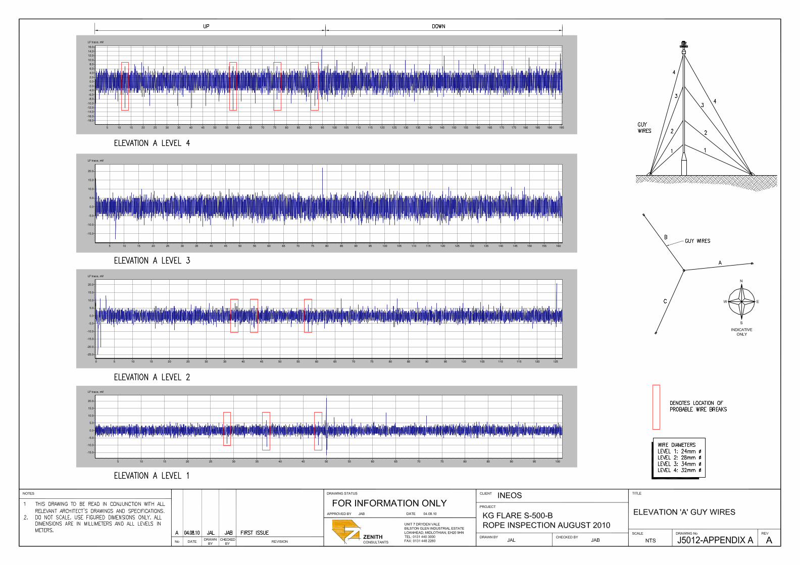
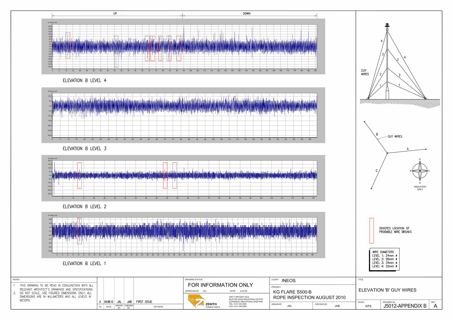
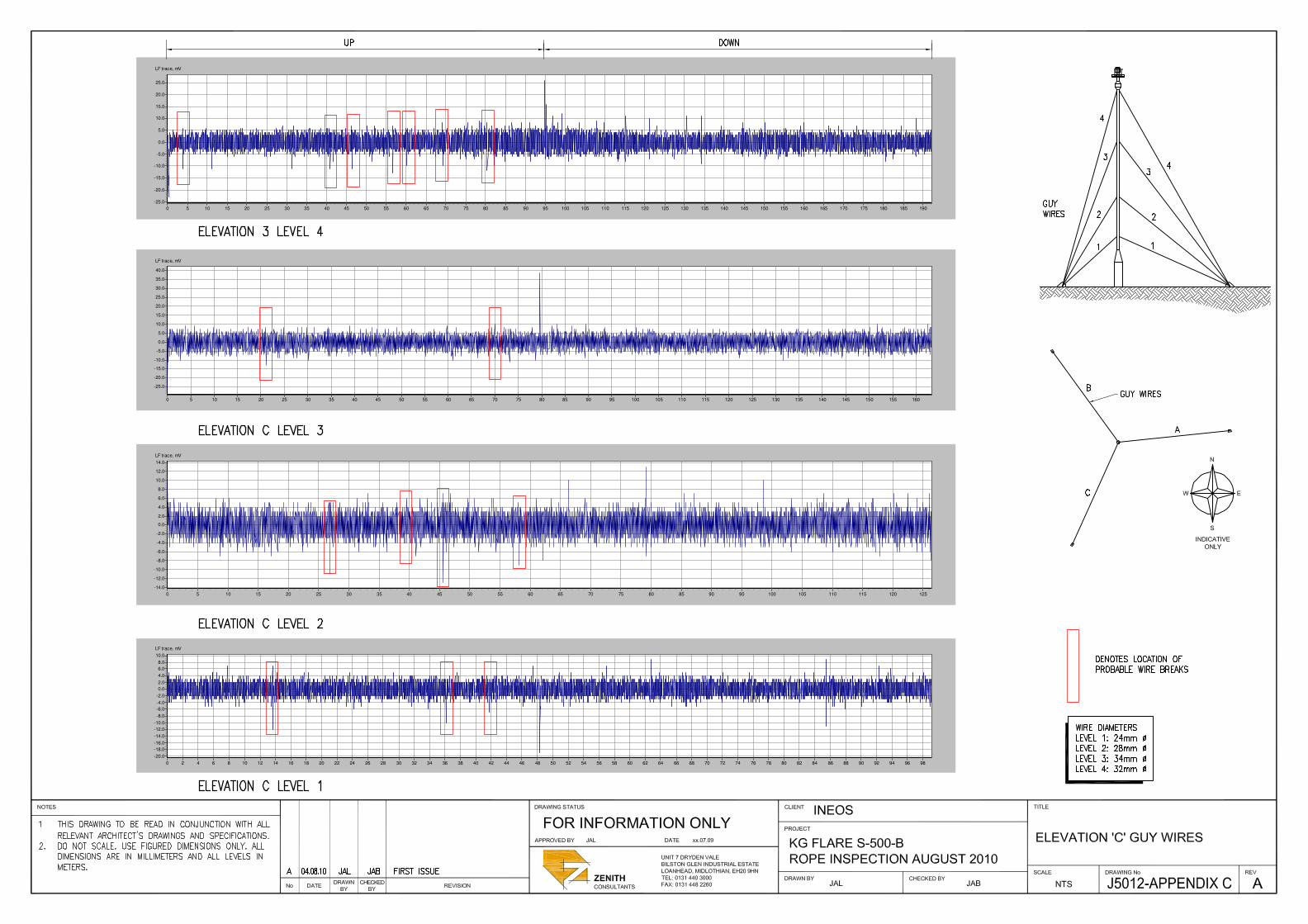
4.8 Guy Wire Inspection: Guy wires are in generally good condition, there are however a number of broken wires within some of the cables, but the small number of breaks will have no effect on the stability of the flare. Loss of the metallic coat on the wires over localized areas is evident from the survey data. Refer to Appendix A, B & C for survey results of the guy wires.
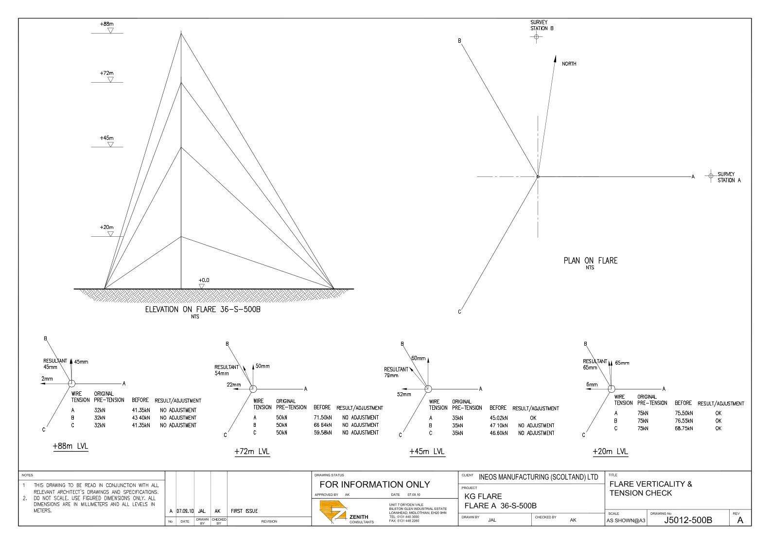
Verticality & Rope Tension
4.9 The results of the verticality and rope tension are appended (Appendix D).
4.10 The tension figures in the lower ropes are generally in line with pre-
tension design figures. The recorded information does not reflect the tension values obtained in the previous year’s measurements, the recorded information for this year is consistently higher than the 2009 readings.
4.11 The variation in readings could be due a variation in site wind speed,
wind direction, gusting, site temperature, operating temperature etc. If the site variables are low during one survey, a relatively modest increase of the variables in the next survey could result in a threefold increase in load.
4.12 In the absence of the original calculations Zenith have adopted a
comparison against of the tension figures suggested by ‘Guydes’, (Guydes being one of the leading software packages for the design of guyed stacks).
4.13 For the purpose of comparison, good practice suggests guy stacks
are typically set at pretension of only 6% to 12% of the breaking strength due to the hot gases flowing into the stacks.
4.14 The ropes are within these guidelines but remain marginally over
tensioned when compared to the pre-tension design data on record. It would be normal practice to only tension ropes rather than slacken ropes in a scenario where the towers have performed with out fault and show no sign of distress.
4.15 In conclusion the ropes would be re-examined within 12 months
recording all tolerances at site level including temperature and wind speed.
4.16 The verticality of the structure is marginally out with tolerance in the
lower two positions. No correction has been made at this time based on the upper levels of the flare stack being within tolerance. It was determined that any adjustment at this stage would compromise the overall results and therefore no action undertaken.
SECTION 5 - DISCUSSION AND RECOMMENDATIONS
5.0 DISCUSSION AND RECOMMENDATIONS
5.1 The flare guy wires and termination points should be inspected at regular intervals.
5.2 The flare remains serviceable under current operating conditions. 5.3 The flare guy wires are in serviceable condition and should be
re-inspected during the next shutdown in 2014.
5.4 Although there are localized areas where the metal coat to the wire has thinned or has been removed, there is no requirement for any repair work to be carried out at this time.
5.5 A magnetic inspection should be carried out at the next shut down in 2016. The result of which should be read alongside this survey to give a rate of deterioration of the wires.
5.6 Zenith remain satisfied that the guy ropes and the flare stacks are operating within tolerance as the thermal expansion due to hot gases in this instance is limited to the tip of the stack and not throughout the full length hence the tension in the wires can approach the 20% to
5.7 40% generally used for transmission towers restrained by guys.
5.8 The verticality of the tower should be checked at regular intervals (not exceeding 12 months) and where tension has relaxed every effort made to correct the verticality to within the BSEN standards without compromising the overall tolerances.

SECTION 6 – APPENDICES
APPENDICES
A- Elevation ‘A’ guy wires B- Elevation ‘B’ guy wires C- Elevation ‘C’ guy wires D- Verticality & Rope Tension E- Comparison Tables

APPENDIX A- ELEVATION 'A' GUY WIRES
LF trace, mV
1951901851801751701651601551501451401351301251201151101051009590858075706560555045403530252015105
16.0
14.0
12.0
10.0
8.0
6.0
4.0
2.0
0.0
-2.0
-4.0
-6.0
-8.0
-10.0
-12.0
-14.0
-16.0
-18.0
LF trace, mV
1601551501451401351301251201151101051009590858075706560555045403530252015105
20.0
15.0
10.0
5.0
0.0
-5.0
-10.0
-15.0
LF trace, mV
12512011511010510095908580757065605550454035302520151050
20.0
15.0
10.0
5.0
0.0
-5.0
-10.0
-15.0
-20.0
-25.0
LF trace, mV
1009590858075706560555045403530252015105
20.0
15.0
10.0
5.0
0.0
-5.0
-10.0
-15.0

APPENDIX B - ELEVATION '8' GUY WIRES
LF trace, mV
19018518017517016516015515014514013513012512011511010510095908580757065605550454035302520151050
16.0
14.0
12.0
10.0
8.0
6.0
4.0
2.0
0.0
-2.0
-4.0
-6.0
-8.0
-10.0
-12.0
-14.0
-16.0
LF trace, mV
16015515014514013513012512011511010510095908580757065605550454035302520151050
10.0
5.0
0.0
-5.0
-10.0
-15.0
-20.0
-25.0
-30.0
LF trace, mV
1251201151101051009590858075706560555045403530252015105
20.0
15.0
10.0
5.0
0.0
-5.0
-10.0
-15.0
-20.0
-25.0
LF trace, mV
9896949290888684828078767472706866646260585654525048464442403836343230282624222018161412108642
6.0
4.0
2.0
0.0
-2.0
-4.0
-6.0
-8.0
-10.0

APPENDIX C – ELEVATION C GUY WIRES
LF trace, mV
19018518017517016516015515014514013513012512011511010510095908580757065605550454035302520151050
25.0
20.0
15.0
10.0
5.0
0.0
-5.0
-10.0
-15.0
-20.0
-25.0
LF trace, mV
16015515014514013513012512011511010510095908580757065605550454035302520151050
40.0
35.0
30.0
25.0
20.0
15.0
10.0
5.0
0.0
-5.0
-10.0
-15.0
-20.0
-25.0
LF trace, mV
12512011511010510095908580757065605550454035302520151050
14.0
12.0
10.0
8.0
6.0
4.0
2.0
0.0
-2.0
-4.0
-6.0
-8.0
-10.0
-12.0
-14.0
LF trace, mV
98969492908886848280787674727068666462605856545250484644424038363432302826242220181614121086420
10.0
8.0
6.0
4.0
2.0
0.0
-2.0
-4.0
-6.0
-8.0
-10.0
-12.0
-14.0
-16.0
-18.0
-20.0

APPENDIX D - VERTICALITY AND ROPE TENSION

APPENDIX 'E' - COMPARISON TABLES
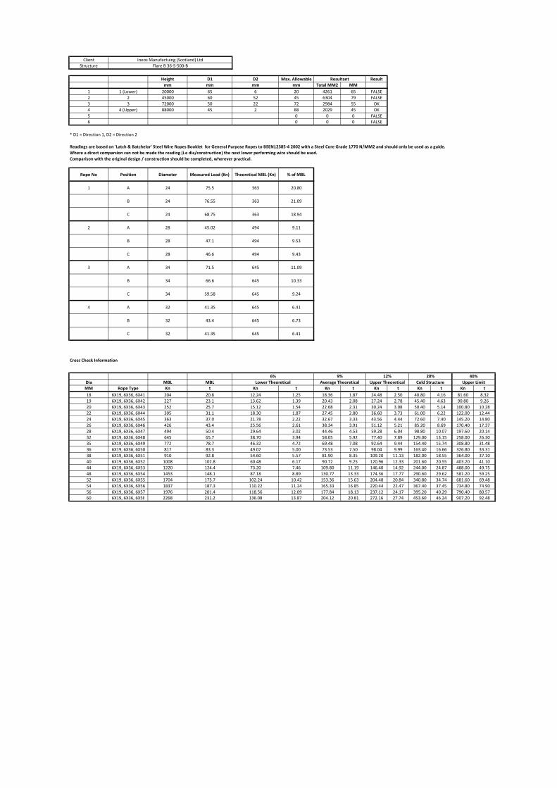
ClientStructure
Height D1 D2 Max. Allowable Resultmm mm mm mm Total MM2 MM
1 1 (Lower) 20000 65 6 20 4261 65 FALSE2 2 45000 60 52 45 6304 79 FALSE3 3 72000 50 22 72 2984 55 OK4 4 (Upper) 88000 45 2 88 2029 45 OK5 0 0 0 FALSE6 0 0 0 FALSE
* D1 = Direction 1, D2 = Direction 2
Readings are based on 'Latch & Batchelor' Steel Wire Ropes Booklet for General Purpose Ropes to BSEN12385‐4 2002 with a Steel Core Grade 1770 N/MM2 and should only be used as a guide.Where a direct comparsion can not be made the reading (i.e dia/construction) the next lower performing wire should be used.Comparison with the original design / construction should be completed, wherever practical.
Rope No Position Diameter Measured Load (Kn) Theoretical MBL (Kn) % of MBL
1 A 24 75.5 363 20.80
B 24 76.55 363 21.09
C 24 68.75 363 18.94
2 A 28 45.02 494 9.11
B 28 47.1 494 9.53
C 28 46.6 494 9.43
3 A 34 71.5 645 11.09
B 34 66.6 645 10.33
C 34 59.58 645 9.24
4 A 32 41.35 645 6.41
B 32 43.4 645 6.73
C 32 41.35 645 6.41
Cross Check Information
Dia MBL MBLMM Rope Type Kn t Kn t Kn t Kn t Kn t Kn t18 6X19, 6X36, 6X41 204 20.8 12.24 1.25 18.36 1.87 24.48 2.50 40.80 4.16 81.60 8.3219 6X19, 6X36, 6X42 227 23.1 13.62 1.39 20.43 2.08 27.24 2.78 45.40 4.63 90.80 9.2620 6X19, 6X36, 6X43 252 25.7 15.12 1.54 22.68 2.31 30.24 3.08 50.40 5.14 100.80 10.2822 6X19, 6X36, 6X44 305 31.1 18.30 1.87 27.45 2.80 36.60 3.73 61.00 6.22 122.00 12.4424 6X19, 6X36, 6X45 363 37.0 21.78 2.22 32.67 3.33 43.56 4.44 72.60 7.40 145.20 14.8026 6X19, 6X36, 6X46 426 43.4 25.56 2.61 38.34 3.91 51.12 5.21 85.20 8.69 170.40 17.3728 6X19, 6X36, 6X47 494 50.4 29.64 3.02 44.46 4.53 59.28 6.04 98.80 10.07 197.60 20.1432 6X19, 6X36, 6X48 645 65.7 38.70 3.94 58.05 5.92 77.40 7.89 129.00 13.15 258.00 26.3035 6X19, 6X36, 6X49 772 78.7 46.32 4.72 69.48 7.08 92.64 9.44 154.40 15.74 308.80 31.4836 6X19, 6X36, 6X50 817 83.3 49.02 5.00 73.53 7.50 98.04 9.99 163.40 16.66 326.80 33.3138 6X19, 6X36, 6X51 910 92.8 54.60 5.57 81.90 8.35 109.20 11.13 182.00 18.55 364.00 37.1040 6X19, 6X36, 6X52 1008 102.8 60.48 6.17 90.72 9.25 120.96 12.33 201.60 20.55 403.20 41.1044 6X19, 6X36, 6X53 1220 124.4 73.20 7.46 109.80 11.19 146.40 14.92 244.00 24.87 488.00 49.7548 6X19, 6X36, 6X54 1453 148.1 87.18 8.89 130.77 13.33 174.36 17.77 290.60 29.62 581.20 59.2552 6X19, 6X36, 6X55 1704 173.7 102.24 10.42 153.36 15.63 204.48 20.84 340.80 34.74 681.60 69.4854 6X19, 6X36, 6X56 1837 187.3 110.22 11.24 165.33 16.85 220.44 22.47 367.40 37.45 734.80 74.9056 6X19, 6X36, 6X57 1976 201.4 118.56 12.09 177.84 18.13 237.12 24.17 395.20 40.29 790.40 80.5760 6X19, 6X36, 6X58 2268 231.2 136.08 13.87 204.12 20.81 272.16 27.74 453.60 46.24 907.20 92.48
12% 40%Upper Limit
Ineos Manufactuing (Scotland) LtdFlare B 36‐S‐500‐B
20%Cold Structure
Resultant
Lower Theoretical Average Theoretical Upper Theoretical6% 9%

Appendix ii -Instructions for Use

Appendix iii- Manufacturers Brochure