Embed Size (px)
Citation preview

ibm.com/redbooks
A Guide to UsingACI Worldwide’s BASE24-es on z/OS
Alex LouweKooijmans
Edward AddisonAlexei AlaevDan Archer
Gordon FlemingClaus Koefoed
Ron SchmidtBob Spanke
Mingming TaoDore Teichman
Set up and use BASE24-es on z/OS
High availability scenarios
Configure for highest availability
Front cover

A Guide to Using ACI Worldwide’s BASE24-es on z/OS
August 2006
International Technical Support Organization
SG24-7268-00
© Copyright International Business Machines Corporation 2006. All rights reserved.Note to U.S. Government Users Restricted Rights -- Use, duplication or disclosure restricted by GSA ADPSchedule Contract with IBM Corp.
First Edition (August 2006)
This edition applies to Release 1, Version 06.2 of ACI Worldwide’s BASE24-es product on z/OS.
Note: Before using this information and the product it supports, read the information in “Notices” on page vii.
Contents
Notices . . . . . . . . . . . . . . . . . . . . . . . . . . . . . . . . . . . . . . . . . . . . . . . . . . . . . . viiTrademarks . . . . . . . . . . . . . . . . . . . . . . . . . . . . . . . . . . . . . . . . . . . . . . . . . . . viii
Preface . . . . . . . . . . . . . . . . . . . . . . . . . . . . . . . . . . . . . . . . . . . . . . . . . . . . . . . ixThe team that wrote this redbook. . . . . . . . . . . . . . . . . . . . . . . . . . . . . . . . . . . . xBecome a published author . . . . . . . . . . . . . . . . . . . . . . . . . . . . . . . . . . . . . . . xiiComments welcome. . . . . . . . . . . . . . . . . . . . . . . . . . . . . . . . . . . . . . . . . . . . . xii
Chapter 1. Running a payments system . . . . . . . . . . . . . . . . . . . . . . . . . . . . 11.1 Industry growth . . . . . . . . . . . . . . . . . . . . . . . . . . . . . . . . . . . . . . . . . . . . . . 2
1.1.1 The requirement for reliability . . . . . . . . . . . . . . . . . . . . . . . . . . . . . . . 21.1.2 System availability. . . . . . . . . . . . . . . . . . . . . . . . . . . . . . . . . . . . . . . . 21.1.3 Basic banking transaction categories . . . . . . . . . . . . . . . . . . . . . . . . . 3
1.2 How ATM and POS processing is accomplished . . . . . . . . . . . . . . . . . . . . 41.2.1 Transaction acquisition and authorization. . . . . . . . . . . . . . . . . . . . . . 7
1.3 How System z addresses ATM/EFT/POS processing requirements . . . . . 71.3.1 Availability . . . . . . . . . . . . . . . . . . . . . . . . . . . . . . . . . . . . . . . . . . . . . . 71.3.2 Parallel Sysplex clustering . . . . . . . . . . . . . . . . . . . . . . . . . . . . . . . . . 81.3.3 Manageability . . . . . . . . . . . . . . . . . . . . . . . . . . . . . . . . . . . . . . . . . . . 91.3.4 Security . . . . . . . . . . . . . . . . . . . . . . . . . . . . . . . . . . . . . . . . . . . . . . . 101.3.5 Expandability . . . . . . . . . . . . . . . . . . . . . . . . . . . . . . . . . . . . . . . . . . . 101.3.6 Dynamic workload balancing . . . . . . . . . . . . . . . . . . . . . . . . . . . . . . 11
Chapter 2. Introducing BASE24-es . . . . . . . . . . . . . . . . . . . . . . . . . . . . . . . 132.1 BASE24-es . . . . . . . . . . . . . . . . . . . . . . . . . . . . . . . . . . . . . . . . . . . . . . . . 14
2.1.1 Consumer transaction support . . . . . . . . . . . . . . . . . . . . . . . . . . . . . 142.1.2 Transaction switching and routing. . . . . . . . . . . . . . . . . . . . . . . . . . . 142.1.3 Flexible authorization . . . . . . . . . . . . . . . . . . . . . . . . . . . . . . . . . . . . 152.1.4 Integrated consumer data . . . . . . . . . . . . . . . . . . . . . . . . . . . . . . . . . 152.1.5 Traditional and emerging delivery channels . . . . . . . . . . . . . . . . . . . 162.1.6 Reliable security infrastructure . . . . . . . . . . . . . . . . . . . . . . . . . . . . . 162.1.7 Intuitive graphical user interface . . . . . . . . . . . . . . . . . . . . . . . . . . . . 172.1.8 Scriptable extracts and reports . . . . . . . . . . . . . . . . . . . . . . . . . . . . . 172.1.9 National switch and international card scheme interfaces . . . . . . . . 17
2.2 Architecture . . . . . . . . . . . . . . . . . . . . . . . . . . . . . . . . . . . . . . . . . . . . . . . . 172.3 Operability . . . . . . . . . . . . . . . . . . . . . . . . . . . . . . . . . . . . . . . . . . . . . . . . . 192.4 Scripting component . . . . . . . . . . . . . . . . . . . . . . . . . . . . . . . . . . . . . . . . . 192.5 The user interface . . . . . . . . . . . . . . . . . . . . . . . . . . . . . . . . . . . . . . . . . . . 202.6 Rich functionality . . . . . . . . . . . . . . . . . . . . . . . . . . . . . . . . . . . . . . . . . . . . 21
© Copyright IBM Corp. 2006. All rights reserved. iii
2.7 Platform independence . . . . . . . . . . . . . . . . . . . . . . . . . . . . . . . . . . . . . . . 212.8 Flexible architecture . . . . . . . . . . . . . . . . . . . . . . . . . . . . . . . . . . . . . . . . . 212.9 The ACI Payments Framework . . . . . . . . . . . . . . . . . . . . . . . . . . . . . . . . . 21
Chapter 3. System z and z/OS . . . . . . . . . . . . . . . . . . . . . . . . . . . . . . . . . . . 233.1 How z/OS addresses non-functional requirements . . . . . . . . . . . . . . . . . . 24
3.1.1 Background . . . . . . . . . . . . . . . . . . . . . . . . . . . . . . . . . . . . . . . . . . . . 243.1.2 Traditional z/OS strengths. . . . . . . . . . . . . . . . . . . . . . . . . . . . . . . . . 243.1.3 Centralized computing model . . . . . . . . . . . . . . . . . . . . . . . . . . . . . . 25
Chapter 4. BASE24-es technical architecture on z/OS . . . . . . . . . . . . . . . 414.1 BASE24-es logical architecture. . . . . . . . . . . . . . . . . . . . . . . . . . . . . . . . . 42
4.1.1 Memory-based message queuing. . . . . . . . . . . . . . . . . . . . . . . . . . . 424.1.2 Indexed structured file system or relational database. . . . . . . . . . . . 434.1.3 Transaction manager . . . . . . . . . . . . . . . . . . . . . . . . . . . . . . . . . . . . 434.1.4 Data communications . . . . . . . . . . . . . . . . . . . . . . . . . . . . . . . . . . . . 434.1.5 Other requirements . . . . . . . . . . . . . . . . . . . . . . . . . . . . . . . . . . . . . . 44
4.2 BASE24-es physical architecture on System z . . . . . . . . . . . . . . . . . . . . . 444.2.1 Long-running tasks . . . . . . . . . . . . . . . . . . . . . . . . . . . . . . . . . . . . . . 444.2.2 Non-recoverable TDQs . . . . . . . . . . . . . . . . . . . . . . . . . . . . . . . . . . . 454.2.3 Context-free servers . . . . . . . . . . . . . . . . . . . . . . . . . . . . . . . . . . . . . 454.2.4 Message routing . . . . . . . . . . . . . . . . . . . . . . . . . . . . . . . . . . . . . . . . 454.2.5 Single-region deployment . . . . . . . . . . . . . . . . . . . . . . . . . . . . . . . . . 464.2.6 Two-tier deployment . . . . . . . . . . . . . . . . . . . . . . . . . . . . . . . . . . . . . 474.2.7 Three-tier deployment . . . . . . . . . . . . . . . . . . . . . . . . . . . . . . . . . . . . 484.2.8 Workload management . . . . . . . . . . . . . . . . . . . . . . . . . . . . . . . . . . . 484.2.9 TOR architecture. . . . . . . . . . . . . . . . . . . . . . . . . . . . . . . . . . . . . . . . 504.2.10 AOR architecture. . . . . . . . . . . . . . . . . . . . . . . . . . . . . . . . . . . . . . . 564.2.11 Financial transaction flow . . . . . . . . . . . . . . . . . . . . . . . . . . . . . . . . 874.2.12 BASE24-es logical architecture on z/OS. . . . . . . . . . . . . . . . . . . . . 904.2.13 User interface region architecture . . . . . . . . . . . . . . . . . . . . . . . . . . 904.2.14 Scalability considerations . . . . . . . . . . . . . . . . . . . . . . . . . . . . . . . . 94
Chapter 5. Designing the system layout . . . . . . . . . . . . . . . . . . . . . . . . . . . 995.1 Pain versus gain . . . . . . . . . . . . . . . . . . . . . . . . . . . . . . . . . . . . . . . . . . . 100
5.1.1 Planned versus unplanned outages . . . . . . . . . . . . . . . . . . . . . . . . 1005.1.2 Single site versus dual site . . . . . . . . . . . . . . . . . . . . . . . . . . . . . . . 100
5.2 High availability considerations . . . . . . . . . . . . . . . . . . . . . . . . . . . . . . . . 1015.2.1 Terminal Owning Regions (TORs) . . . . . . . . . . . . . . . . . . . . . . . . . 1015.2.2 Application Owning Regions (AORs) . . . . . . . . . . . . . . . . . . . . . . . 1055.2.3 File access . . . . . . . . . . . . . . . . . . . . . . . . . . . . . . . . . . . . . . . . . . . 1065.2.4 External system connectivity . . . . . . . . . . . . . . . . . . . . . . . . . . . . . . 1145.2.5 Back-end authorization system connectivity . . . . . . . . . . . . . . . . . . 114
5.3 BASE24-es configurations . . . . . . . . . . . . . . . . . . . . . . . . . . . . . . . . . . . 115
iv A Guide to Using ACI Worldwide’s BASE24-es on z/OS
5.3.1 Single LPAR . . . . . . . . . . . . . . . . . . . . . . . . . . . . . . . . . . . . . . . . . . 1165.3.2 Multiple LPARs/Single CPCs . . . . . . . . . . . . . . . . . . . . . . . . . . . . . 1185.3.3 Multiple LPARs/Multiple CPCs . . . . . . . . . . . . . . . . . . . . . . . . . . . . 1195.3.4 Multiple LPARs/Multiple CPCs/Dual site . . . . . . . . . . . . . . . . . . . . . 120
Chapter 6. Installing BASE24-es on z/OS . . . . . . . . . . . . . . . . . . . . . . . . . 1236.1 The ITSO environment . . . . . . . . . . . . . . . . . . . . . . . . . . . . . . . . . . . . . . 124
6.1.1 Hardware we used . . . . . . . . . . . . . . . . . . . . . . . . . . . . . . . . . . . . . 1246.1.2 Software we used . . . . . . . . . . . . . . . . . . . . . . . . . . . . . . . . . . . . . . 125
6.2 BASE24-es requirements . . . . . . . . . . . . . . . . . . . . . . . . . . . . . . . . . . . . 1256.2.1 Hardware requirements. . . . . . . . . . . . . . . . . . . . . . . . . . . . . . . . . . 1266.2.2 Software requirements . . . . . . . . . . . . . . . . . . . . . . . . . . . . . . . . . . 1266.2.3 Desktop . . . . . . . . . . . . . . . . . . . . . . . . . . . . . . . . . . . . . . . . . . . . . . 126
6.3 Overview of pre-installation steps . . . . . . . . . . . . . . . . . . . . . . . . . . . . . . 1276.3.1 General considerations . . . . . . . . . . . . . . . . . . . . . . . . . . . . . . . . . . 1276.3.2 Installing and implementing the workstation requirements . . . . . . . 1286.3.3 Additional requirements . . . . . . . . . . . . . . . . . . . . . . . . . . . . . . . . . 1286.3.4 New time library . . . . . . . . . . . . . . . . . . . . . . . . . . . . . . . . . . . . . . . 129
6.4 Installation considerations . . . . . . . . . . . . . . . . . . . . . . . . . . . . . . . . . . . . 1296.4.1 Expanding the BASE24-es installation to a CICSplex . . . . . . . . . . 132
6.5 Setting up integration with the back-end system. . . . . . . . . . . . . . . . . . . 133
Chapter 7. Setting up and running the initial workload . . . . . . . . . . . . . . 1377.1 Setting up the workload. . . . . . . . . . . . . . . . . . . . . . . . . . . . . . . . . . . . . . 138
7.1.1 Configuring the BASE24-es infrastructure . . . . . . . . . . . . . . . . . . . 1387.1.2 Business configuration . . . . . . . . . . . . . . . . . . . . . . . . . . . . . . . . . . 142
7.2 Our ITSO system layout . . . . . . . . . . . . . . . . . . . . . . . . . . . . . . . . . . . . . 1427.3 Setting up monitoring . . . . . . . . . . . . . . . . . . . . . . . . . . . . . . . . . . . . . . . 143
7.3.1 Routing region. . . . . . . . . . . . . . . . . . . . . . . . . . . . . . . . . . . . . . . . . 1447.3.2 Target region. . . . . . . . . . . . . . . . . . . . . . . . . . . . . . . . . . . . . . . . . . 144
7.4 Installation verification . . . . . . . . . . . . . . . . . . . . . . . . . . . . . . . . . . . . . . . 1447.4.1 Simulate single transactions . . . . . . . . . . . . . . . . . . . . . . . . . . . . . . 1457.4.2 Increasing the workload . . . . . . . . . . . . . . . . . . . . . . . . . . . . . . . . . 146
Chapter 8. Tuning BASE24-es on z/OS . . . . . . . . . . . . . . . . . . . . . . . . . . . 1498.1 BASE24-es File Partitioning . . . . . . . . . . . . . . . . . . . . . . . . . . . . . . . . . . 1508.2 Basic considerations . . . . . . . . . . . . . . . . . . . . . . . . . . . . . . . . . . . . . . . . 1508.3 Single files as potential bottlenecks . . . . . . . . . . . . . . . . . . . . . . . . . . . . 1518.4 CICS logging impacts . . . . . . . . . . . . . . . . . . . . . . . . . . . . . . . . . . . . . . . 1568.5 RMF Monitor III indicator . . . . . . . . . . . . . . . . . . . . . . . . . . . . . . . . . . . . . 156
Chapter 9. Achieving high availability on z/OS . . . . . . . . . . . . . . . . . . . . 1599.1 Test scenarios . . . . . . . . . . . . . . . . . . . . . . . . . . . . . . . . . . . . . . . . . . . . . 1609.2 CICS and CP/SM . . . . . . . . . . . . . . . . . . . . . . . . . . . . . . . . . . . . . . . . . . 160
Contents v
9.2.1 CMAS failure after workload has been activated . . . . . . . . . . . . . . 1609.2.2 TCP/IP client - TOR failure . . . . . . . . . . . . . . . . . . . . . . . . . . . . . . . 1619.2.3 TCP/IP server - TOR failure . . . . . . . . . . . . . . . . . . . . . . . . . . . . . . 1639.2.4 AOR failure . . . . . . . . . . . . . . . . . . . . . . . . . . . . . . . . . . . . . . . . . . . 1659.2.5 TCP/IP server - TOR maintenance . . . . . . . . . . . . . . . . . . . . . . . . . 1679.2.6 AOR maintenance. . . . . . . . . . . . . . . . . . . . . . . . . . . . . . . . . . . . . . 1689.2.7 Dynamically adding a TOR . . . . . . . . . . . . . . . . . . . . . . . . . . . . . . . 1709.2.8 Dynamically adding an AOR . . . . . . . . . . . . . . . . . . . . . . . . . . . . . . 172
9.3 Data environment . . . . . . . . . . . . . . . . . . . . . . . . . . . . . . . . . . . . . . . . . . 1749.3.1 SMSVSAM failure . . . . . . . . . . . . . . . . . . . . . . . . . . . . . . . . . . . . . . 1749.3.2 Lock structure full - IGWLOCK00 . . . . . . . . . . . . . . . . . . . . . . . . . . 1769.3.3 Read-only data table at initial time . . . . . . . . . . . . . . . . . . . . . . . . . 1849.3.4 Read-only flat file at initial time . . . . . . . . . . . . . . . . . . . . . . . . . . . . 185
9.4 BASE24-es application . . . . . . . . . . . . . . . . . . . . . . . . . . . . . . . . . . . . . . 1869.4.1 Journal file full . . . . . . . . . . . . . . . . . . . . . . . . . . . . . . . . . . . . . . . . . 1869.4.2 IP client failure. . . . . . . . . . . . . . . . . . . . . . . . . . . . . . . . . . . . . . . . . 1899.4.3 IP Server failure . . . . . . . . . . . . . . . . . . . . . . . . . . . . . . . . . . . . . . . 1919.4.4 Integrated Server failure . . . . . . . . . . . . . . . . . . . . . . . . . . . . . . . . . 1949.4.5 Planned application upgrade. . . . . . . . . . . . . . . . . . . . . . . . . . . . . . 1989.4.6 Remote program link to back-end authorization failure. . . . . . . . . . 2029.4.7 Usage file full. . . . . . . . . . . . . . . . . . . . . . . . . . . . . . . . . . . . . . . . . . 204
9.5 Hardware. . . . . . . . . . . . . . . . . . . . . . . . . . . . . . . . . . . . . . . . . . . . . . . . . 2069.5.1 Central Processor (CP) failure . . . . . . . . . . . . . . . . . . . . . . . . . . . . 2069.5.2 CPC failure/LPAR failure. . . . . . . . . . . . . . . . . . . . . . . . . . . . . . . . . 2099.5.3 Coupling Facility (CF) failure. . . . . . . . . . . . . . . . . . . . . . . . . . . . . . 211
9.6 z/OS and relevant subsystems . . . . . . . . . . . . . . . . . . . . . . . . . . . . . . . . 2149.6.1 z/OS maintenance - best practices . . . . . . . . . . . . . . . . . . . . . . . . . 2159.6.2 CF maintenance - best practices . . . . . . . . . . . . . . . . . . . . . . . . . . 215
Chapter 10. Conclusion . . . . . . . . . . . . . . . . . . . . . . . . . . . . . . . . . . . . . . . 21910.1 Summary . . . . . . . . . . . . . . . . . . . . . . . . . . . . . . . . . . . . . . . . . . . . . . . . 22010.2 The payment environment requirements. . . . . . . . . . . . . . . . . . . . . . . . 220
10.2.1 Conclusions. . . . . . . . . . . . . . . . . . . . . . . . . . . . . . . . . . . . . . . . . . 221
Glossary . . . . . . . . . . . . . . . . . . . . . . . . . . . . . . . . . . . . . . . . . . . . . . . . . . . . 223
Related publications . . . . . . . . . . . . . . . . . . . . . . . . . . . . . . . . . . . . . . . . . . 227IBM Redbooks . . . . . . . . . . . . . . . . . . . . . . . . . . . . . . . . . . . . . . . . . . . . . . . . 227Other publications . . . . . . . . . . . . . . . . . . . . . . . . . . . . . . . . . . . . . . . . . . . . . 227Online resources . . . . . . . . . . . . . . . . . . . . . . . . . . . . . . . . . . . . . . . . . . . . . . 227How to get IBM Redbooks . . . . . . . . . . . . . . . . . . . . . . . . . . . . . . . . . . . . . . . 227Help from IBM . . . . . . . . . . . . . . . . . . . . . . . . . . . . . . . . . . . . . . . . . . . . . . . . 228
Index . . . . . . . . . . . . . . . . . . . . . . . . . . . . . . . . . . . . . . . . . . . . . . . . . . . . . . . 229
vi A Guide to Using ACI Worldwide’s BASE24-es on z/OS

Notices
This information was developed for products and services offered in the U.S.A.
IBM® may not offer the products, services, or features discussed in this document in other countries. Consult your local IBM representative for information on the products and services currently available in your area. Any reference to an IBM product, program, or service is not intended to state or imply that only that IBM product, program, or service may be used. Any functionally equivalent product, program, or service that does not infringe any IBM intellectual property right may be used instead. However, it is the user's responsibility to evaluate and verify the operation of any non-IBM product, program, or service.
IBM may have patents or pending patent applications covering subject matter described in this document. The furnishing of this document does not give you any license to these patents. You can send license inquiries, in writing, to: IBM Director of Licensing, IBM Corporation, North Castle Drive Armonk, NY 10504-1785 U.S.A.
The following paragraph does not apply to the United Kingdom or any other country where such provisions are inconsistent with local law: INTERNATIONAL BUSINESS MACHINES CORPORATION PROVIDES THIS PUBLICATION "AS IS" WITHOUT WARRANTY OF ANY KIND, EITHER EXPRESS OR IMPLIED, INCLUDING, BUT NOT LIMITED TO, THE IMPLIED WARRANTIES OF NON-INFRINGEMENT, MERCHANTABILITY OR FITNESS FOR A PARTICULAR PURPOSE. Some states do not allow disclaimer of express or implied warranties in certain transactions, therefore, this statement may not apply to you.
This information could include technical inaccuracies or typographical errors. Changes are periodically made to the information herein; these changes will be incorporated in new editions of the publication. IBM may make improvements and/or changes in the product(s) and/or the program(s) described in this publication at any time without notice.
Any references in this information to non-IBM Web sites are provided for convenience only and do not in any manner serve as an endorsement of those Web sites. The materials at those Web sites are not part of the materials for this IBM product and use of those Web sites is at your own risk.
IBM may use or distribute any of the information you supply in any way it believes appropriate without incurring any obligation to you.
Information concerning non-IBM products was obtained from the suppliers of those products, their published announcements or other publicly available sources. IBM has not tested those products and cannot confirm the accuracy of performance, compatibility or any other claims related to non-IBM products. Questions on the capabilities of non-IBM products should be addressed to the suppliers of those products.
This information contains examples of data and reports used in daily business operations. To illustrate them as completely as possible, the examples include the names of individuals, companies, brands, and products. All of these names are fictitious and any similarity to the names and addresses used by an actual business enterprise is entirely coincidental.
COPYRIGHT LICENSE: This information contains sample application programs in source language, which illustrates programming techniques on various operating platforms. You may copy, modify, and distribute these sample programs in any form without payment to IBM, for the purposes of developing, using, marketing or distributing application programs conforming to the application programming interface for the operating platform for which the sample programs are written. These examples have not been thoroughly tested under all conditions. IBM, therefore, cannot guarantee or imply reliability, serviceability, or function of these programs. You may copy, modify, and distribute these sample programs in any form without payment to IBM for the purposes of developing, using, marketing, or distributing application programs conforming to IBM's application programming interfaces.
© Copyright IBM Corp. 2006. All rights reserved. vii

TrademarksThe following terms are trademarks of the International Business Machines Corporation in the United States, other countries, or both:
Eserver
Eserver
eServer™AIX®Chipkill™CICS®CICS/ESA®CICSPlex®DB2®DFSORT™DS6000™DS8000™FlashCopy®Geographically Dispersed
Parallel Sysplex™GDPS®HiperSockets™IBM®IMS™Language Environment®Maestro™MVS™OS/390®Parallel Sysplex®pSeries®Redbooks™Redbooks (logo)RACF®
RMF™Sysplex Timer®System z™System z9™Tivoli®Tivoli Enterprise™TotalStorage®VTAM®WebSphere®z9™z/OS®zSeries®z/VM®z/VSE™®
The following terms are trademarks of other companies:
ACI, ACI Worldwide, and BASE24-es are trademarks or registered trademarks of ACI Worldwide Inc. or its affiliates in the United States, other countries or both.
Java™, JSP™, and all Java-based trademarks are trademarks of Sun™ Microsystems™, Inc. in the United States, other countries, or both.
Windows®, and the Windows logo are trademarks of Microsoft® Corporation in the United States, other countries, or both.
Intel®, Intel logo, Intel Inside®, Intel Inside logo, Intel Centrino, Intel Centrino logo, Celeron®, Intel Xeon®, Intel SpeedStep®, Itanium®, and Pentium® are trademarks or registered trademarks of Intel Corporation or its subsidiaries in the United States and other countries.
UNIX® is a registered trademark of The Open Group in the United States and other countries.
Linux™ is a trademark of Linus Torvalds in the United States, other countries, or both.
Other company, product, or service names may be trademarks or service marks of others.
viii A Guide to Using ACI Worldwide’s BASE24-es on z/OS

Preface
In this IBM® Redbook we explain how to use the ACI BASE24-es product on z/OS®. BASE24-es is a payment engine utilized by the financial payments industry. The combination of BASE24-es and System z™ is a competitive and attractive end-to-end retail payments solution for the finance sector.
Failure in a financial payments environment is a high-visibility customer service issue, and outages at any level have debilitating effects on customer loyalty. The entire payments cycle must be conducted in near real-time. In such an environment, high availability is a mission-critical requirement. In this guide, we demonstrate how you can achieve a high availability configuration for BASE24-es on z/OS.
We begin by outlining the requirements of a payments system, and then introduce the structure and functionality offered by the BASE24-es product. Next we describe the strengths and abilities of System z and z/OS, and explain the technical and physical architecture of BASE24-es on z/OS.
We guide you in designing a system layout and in installing, tailoring, and configuring your workload on z/OS. Finally, we detail the numerous failure scenarios that we tested in order to verify the robustness of the solution. These test scenarios were carefully selected in areas such as CICS/CICSplex, data environment, BASE24-es application, and hardware. Communication was handled by ATM or POS device simulators and a Visa network simulator. (Testing for high availability of communication, however, was beyond the scope of this redbook.)
This redbook is focused on business verification and can be used by system administrators who work with payment transactions systems. It will help you to achieve the highest possible availability on z/OS by running the supplied test scenarios.
BASE24-es is an evolving product. The information provided in this redbook is specific to BASE24-es release 06.2, and is subject to change in subsequent releases of the product.
© Copyright IBM Corp. 2006. All rights reserved. ix
The team that wrote this redbookThis redbook was produced by a team of specialists from around the world working at the International Technical Support Organization, Poughkeepsie Center.
Alex Louwe Kooijmans is a Project Leader with the International Technical Support Organization (ITSO) in Poughkeepsie, NY. He specializes in WebSphere®, Java™ and SOA on System z with a focus on integration, security, high availability and application development. Previously, he worked as a Client IT Architect in the Financial Services sector with IBM in The Netherlands, advising financial services companies on IT issues such as software and hardware strategy and on demand. Alex has also worked at the Technical Marketing Competence Center for zSeries® and Linux in Boeblingen, Germany, providing support to customers implementing Java and WebSphere on zSeries. From 1997 to 2002, he worked on a previous assignment with the ITSO, managing various IBM Redbook projects and delivering workshops around the world.
Edward Addison is a Software Engineer working in Raleigh, NC as the Technical Lead for CICS® Level 2 support. Prior to working at CICS Level 2, he was a member of the VSAM Level 2 support group in San Jose, CA. Edward has been with IBM for 18 years, supporting customer VSAM and CICS. He holds a BS degree in Information Systems from the University of Phoenix.
Alexei Alaev is a Senior Engineer with ACI Worldwide, located in the USA. Alexei has 28 years of experience in the IT industry. He holds degrees in Computer Science from Moscow State University in Russia. His areas of expertise include IBM mainframe application and system programming, including the sysplex environment. For the past 8 years, Alexei has been working on the development and implementation of the multi-platform BASE24-es application.
Dan Archer is a Senior Product Manager with ACI Worldwide Inc. located in Omaha, NE. He has 11 years of online transaction processing experience with ACI, and has provided technical support of BASE24-es since its inception.
Gordon Fleming is a Master Engineer with ACI Worldwide Inc., located in the USA. He has 19 years of experience in online transaction processing, primarily in BASE24 and BASE24-es development. He holds degrees from the University of Chicago and the University of Nebraska at Omaha. His areas of expertise include multi-platform infrastructure design and implementation.
Claus Koefoed is a Program Manager/zSeries from CompeteCenter in IBM Denmark. He has 30 years of experience in the I/T industry with IBM. His area of professional focus is on IBM mainframe competition, EFT solutions. Claus is
x A Guide to Using ACI Worldwide’s BASE24-es on z/OS
editor of a newsletter/Sinet on mainframe subjects for the IBM community. He holds a Msc. Econ. from the University of Copenhagen.
Ron Schmidt is a Systems Engineer with ACI Worldwide, Inc., located in the US. He has 15 years of experience in online transaction processing, primarily in TRANS24-eft development/deployment and BASE24-es performance. He holds a degree in Computer Science and Business Administration from Kearney State College. His areas of expertise include development/deployment of online transaction processing systems and the performance analysis of zSeries applications.
Bob Spanke is a Master Engineer in ACI Worldwide's Technical Steering group. He is located in Omaha, NE. Bob has 19 years of online transaction process experience with ACI. His primary area of focus is BASE24-es application architecture. Bob holds Bachelor of Science degrees in Computer Science and Information Systems from Kansas State University.
Mingming Tao is a z/OS Systems Programming leader with the China Merchants Bank Data Center, ShenZhen. He has 9 years of experience with mainframe systems. He holds a degree in Computer Science from FuDan University. His areas of expertise include SNA/IP integration, CICS dump analysis, and performance tuning. He has taught extensively on the subjects of systems programming and database administration.
Dore Teichman is an IBM Certified IT Architect and Open Group Certified Master IT Architect with IBM. He has more than 25 years of experience in online transaction processing, primarily with Base-24 and Tandem, where he served as a Regional Designated Specialist for Performance. He holds a degree in Computer Information Systems and Engineering from California Polytechnic University. His areas of expertise are Performance Engineering, deployment and optimization of high volume online transaction processing systems, and Server Consolidation. Prior to joining IBM, Dore served as a Regionally Designated Specialist for performance with Tandem Computers, Inc., and is the original author of Guardian Performance Analyzer.
Thanks to the following people for their contributions to this project:
Paola Bari, Robert HaimowitzInternational Technical Support Organization, Poughkeepsie Center
Stephen AnaniaIBM Poughkeepsie
Ron Beauchamp, Rick Doty, Ajit Godbole, Jeff Hansen, Karen Jarnecic, Kurt Lawrence, Charlie Linberg, Catherine McCarthy, Calvin RobertsonACI Worldwide
Preface xi

Become a published authorJoin us for a two- to six-week residency program! Help write an IBM Redbook dealing with specific products or solutions, while getting hands-on experience with leading-edge technologies. You'll team with IBM technical professionals, Business Partners and/or customers.
Your efforts will help increase product acceptance and customer satisfaction. As a bonus, you'll develop a network of contacts in IBM development labs, and increase your productivity and marketability.
Find out more about the residency program, browse the residency index, and apply online at:
ibm.com/redbooks/residencies.html
Comments welcomeYour comments are important to us!
We want our Redbooks™ to be as helpful as possible. Send us your comments about this or other Redbooks in one of the following ways:
� Use the online Contact us review redbook form found at:
ibm.com/redbooks
� Send your comments in an email to:
� Mail your comments to:
IBM Corporation, International Technical Support OrganizationDept. HYTD Mail Station P0992455 South RoadPoughkeepsie, NY 12601-5400
xii A Guide to Using ACI Worldwide’s BASE24-es on z/OS
Chapter 1. Running a payments system
Banks and financial institutions are highly motivated by competitive forces to broadly deploy automated teller machines (ATMs) and engage in electronic funds transfer (EFT) activities. “The size of the ATM network has a significant impact on the demand for bank deposits”.1 Customers consider the number and location of ATMs in a bank’s network when choosing a bank or financial institution, and have demonstrated that they are willing to pay a surcharge for convenience. While increasing customer convenience, ATMs also save financial institutions money and increase profits by reducing resource costs through automation.
In this chapter we provide an overview of bank payment systems and requirements, and then describe how System z offers the availability, manageability, security, and workload balancing to help you meet those requirements.
1
1 Knittel, C., and V. Stango. 2004. "Compatibility and Pricing with Indirect Network Effects: Evidence from ATMs." NBER working paper 10774
© Copyright IBM Corp. 2006. All rights reserved. 1
1.1 Industry growth
Bank card processing (ATM, point-of-sale (POS) and credit), more than any other activity, wields an immediate and lasting impact on the reputation and image of a financial institution. Banks and credit card companies encourage customers to use their cards, inviting them to essentially live “cashless”. As a result, the ATM and POS marketplace has undergone a rapid, expansive change in recent years.
“Installation of ATMs and the proliferation of Retail POS has been particularly rapid in recent years. ATM growth was 9.3 percent per year from 1983 to 1995 but accelerated to an annual pace of 15.5 percent from 1996 to 2002. Much of the acceleration is due to placing ATMs in locations other than bank offices. These off-premise ATMs accounted for only 26 percent of total U.S. ATMs in 1994, but now account for 60 percent. On the debit card side of the industry, growth has been extremely rapid in point-of-sale (POS) debit card transactions. With an annual growth rate of 32 percent from 1995 to 2002, POS debit is the fastest growing type of payment in the United States. Today it accounts for nearly 12 percent of all retail non-cash payments, a fivefold increase in just five years. Growth has been sharp in both online (PIN-based) and offline (signature-based) debit. From 1995 to 2002, annual growth of online debit was 29 percent, while offline debit grew at 36 percent.”2
1.1.1 The requirement for reliability
Few issues impact the reputation of a financial institution, retailer, or customer more than ATM/credit card processing reliability. Trying to explain that a card being declined is the fault of the bank is a difficult task, and failures at the point-of-sale embarrass customers and damage the reputation of the bank itself. As the transition to a cashless society continues, customers will quickly revert to using cash, and—more damagingly—take their business elsewhere, over a single embarrassing event.
Moreover, the brand name of the ATM has to be considered. Maestro™, Star, and others value their name brand and prefer to avoid being the target of poor performance complaints by banking customers.
1.1.2 System availability
Typically, the issuing financial institution or bank has about 10 seconds for domestic transactions to respond before the network begins to stand in. In some
2 Knittel, C., and V. Stango. 2004. "Compatibility and Pricing with Indirect Network Effects: Evidence from ATMs." NBER working paper 10774.
2 A Guide to Using ACI Worldwide’s BASE24-es on z/OS
instances, such as an overseas banks and gateway transactions, more time is allocated.
In the event that a financial institution is unable to respond to a transaction within a specified time period (usually about 10 seconds), the ATM or POS network may have the right to “stand in” for the bank, and following specified rules, then approve or decline the transaction. This could potentially expose the bank to overdraft of the customer’s account, and the possibility of approving a fraudulent transaction. The specific rules and charges for stand in are usually the result of a negotiated agreement between the financial institution and the shared network.
A financial institution or card issuer with unsatisfactory or poor reliability or poor response-time performance may have to accept the risk of a shared network “standing in” for the bank, an activity that is neither free, nor without risk.
System reliability and data integrityA financial transaction may pass through several switches before it is completed on the round-trip journey from acquisition, to authorization, and back to its starting point, ATM or POS station. When everything goes according to plan, the transaction completes and is prepared for final settlement which may take place real-time, or in some form of batch processing scenario. When failures and errors occur, the host issuer authorizing system must keep track of all transactions, never losing a single one.
There are several methods available for meeting the response time, availability, and data integrity requirements imposed on financial processing systems. These techniques go beyond simple fault-tolerance; the system must be continuously available. Fault tolerance is not a requirement for high availability; it is simply one of the tools that contributes to the high availability capability.
1.1.3 Basic banking transaction categories
ATM or POS processing can occur across multiple paths, either directly (via a bank’s owned ATM typically called “On Us”), or through one of many shared networks where the card holder is using a terminal that is owned and operated by a entity.
An example of the cooperative networks is STAR, owned by First Data Corporation. With more than 1.7 million locations across the United States, handling over 5,700 financial institutions with over 134 million cards, STAR is just one of the many networks available to banks and other financial institutions that can be used to project their financial services to their customer base.
Chapter 1. Running a payments system 3
Common shared networks do more than simply provide credit card and ATM processing. They may also provide other services to financial institutions such as:
� Debit and ATM network � Surcharge-free programs� Deposits, deposit sharing program � Gateway connections � ATM driving � PIN-secured debit, signature debit and stored value card processing � Card authorization, activation and production � Merchant acquirer and agent bank programs � Bill payment services � Risk management and fraud prevention services
Other industry competitors in this marketplace worldwide are Plus, Cirrus, Maestro, Pulse, Multibanco, Interlink, StarNet, Alto, Midas, Euronet and others. In total, there are more than 60 major networks worldwide available to both consumers and financial institutions.
Shared ATM networks provide added availability to financial institution customers, although they can also introduce a certain degree of risk. Most networks require stand-in authorization, which enables a network to authorize transactions when a card issuer or processor cannot do so. However, this in turn may lead to an increased risk of fraud.
To cite a useful example of the levels of uptime that are typically maintained, a major bank ATM processing system in The Netherlands has had zero downtime over the past four years, including maintenance and upgrades. This type of reliability is not unusual for the banking industry; even systems in developing countries maintain availability targets higher than 96%.
1.2 How ATM and POS processing is accomplished
In many ways, ATM and POS processing and POS card processing are similar and follow similar paths though the network and associated systems. Four categories of transaction can take place, as described in Table 1-1.
4 A Guide to Using ACI Worldwide’s BASE24-es on z/OS

Table 1-1 Transaction switching schemes
Transactions are routed through the originating ATM or POS, either the bank’s own network or through some combination of regional or national network. Figure 1-1 demonstrates, at high level, the possible paths that a transaction might follow to completion.
Category Description
On Us The transaction arrives via a bank-owned ATM or POS device and is never routed outside the bank.Example: A customer of the “SampleA” Credit Union uses an ATM card to withdraw money from the ATM located in the local credit union office.
Network On Us The transaction originates from a sharing network such as STAR or Cirrus, in which both the bank and the ATM or POS-owning bank are members of the same network.Example: A local customer travels somewhere away from home and is a member of “SampleA” Credit Union. The customer needs to use an ATM or POS at the “SampleB” Credit Union. Both “SampleA” and “SampleB” are members of the STAR network.
Reciprocal Transaction The card holder initiates a transaction at an ATM or POS owned by a bank that is a member of a different regional network. Example: A New York resident attempts to withdraw money from an ATM or POS in Omaha, Nebraska. An agreement between the network in Nebraska and the network in New York allows the transaction to be switched from one regional network to another.
National Bridge Transactions
The card holder uses an ATM or POS at a bank not their own, and the two banks belong to different regional networks that do not have any agreement. Both banks must belong to the same national network. The transaction is handed from the ATM or POS regional network to the national network, and finally to the authorizing bank’s regional network. In this case, there are three switches involved.
Chapter 1. Running a payments system 5
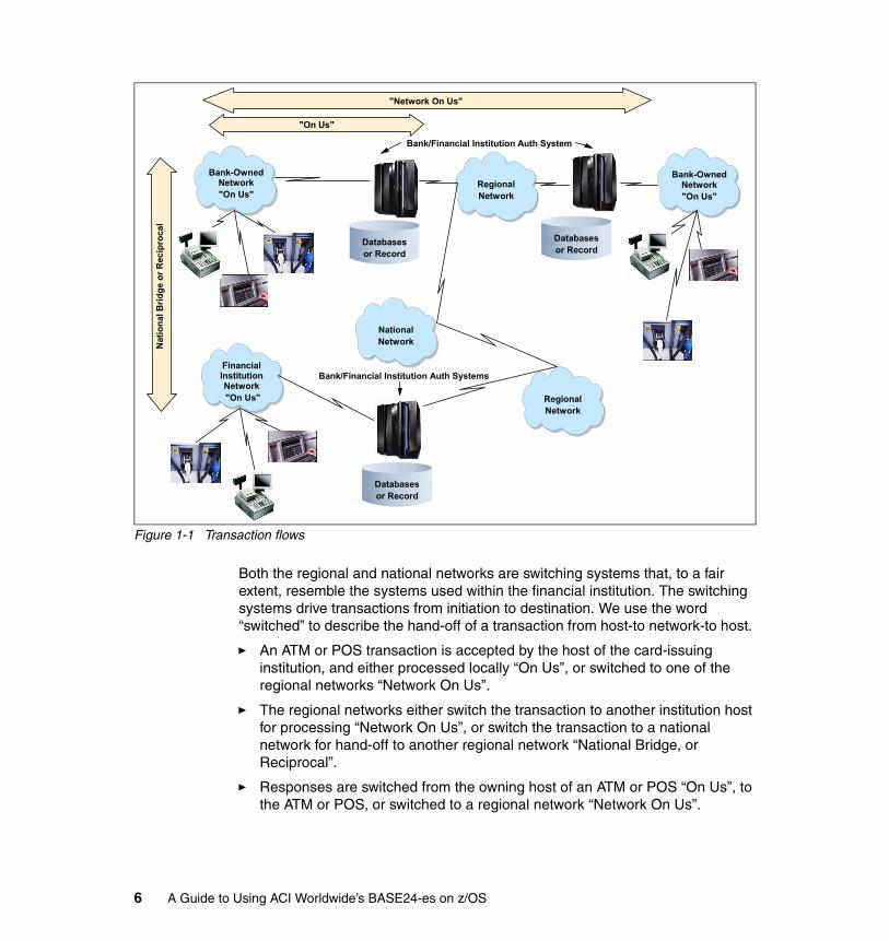
Figure 1-1 Transaction flows
Both the regional and national networks are switching systems that, to a fair extent, resemble the systems used within the financial institution. The switching systems drive transactions from initiation to destination. We use the word “switched” to describe the hand-off of a transaction from host-to network-to host.
� An ATM or POS transaction is accepted by the host of the card-issuing institution, and either processed locally “On Us”, or switched to one of the regional networks “Network On Us”.
� The regional networks either switch the transaction to another institution host for processing “Network On Us”, or switch the transaction to a national network for hand-off to another regional network “National Bridge, or Reciprocal”.
� Responses are switched from the owning host of an ATM or POS “On Us”, to the ATM or POS, or switched to a regional network “Network On Us”.
"Network On Us"
"On Us"
Financial Institution Network "On Us"
Bank-Owned Network"On Us"
Databasesor Record
National Network
Regional Network
Bank-Owned Network"On Us"
Databasesor Record
Databasesor Record
Regional Network
Bank/Financial Institution Auth System
Bank/Financial Institution Auth Systems
Nat
iona
l Brid
ge o
r Rec
ipro
cal
6 A Guide to Using ACI Worldwide’s BASE24-es on z/OS
� The regional network either switches a Host Response to an ATM or POS transaction to the host of a member bank “Network On Us”, or switches the response to a national network “National Bridge, or Reciprocal”.
� The national network switches the response to another regional network for later switching to the card-issuer host.
Although there are other variations on this theme, transactions are switched from host to host via network switches until the original transaction request is completed by a transaction response, or it times out.
1.2.1 Transaction acquisition and authorization
ATM and POS transactions have to traverse three basic steps through complete processing: Acquisition, Authentication, and Authorization. (Back-end settlement and reconciliation activities are not a part of the actual real-time transaction.)
Note that BASE24-es does not have different paths for Authentication and Authorization. Both functions are performed as part of a single task.
1.3 How System z addresses ATM/EFT/POS processing requirements
In the following sections we list the processing requirements that can be met when running on a System z platform. For further details, refer to Chapter 3, “System z and z/OS” on page 23.
1.3.1 Availability
System z provides 24-hour a day, 7-day a week availability, including scheduled maintenance. Continuous availability goes beyond just hardware fault tolerance; it is achieved by a combination of hardware, application code, and good system management practices.
The System z servers are the result of a long evolution beginning in 1964. The sysplex configuration is a high availability solution that not only provides a platform for continuous availability, but also for system maintenance and capacity additions. The System z hardware platform is capable of providing up to five 9s of availability.
On a server basis, System z systems are equipped with features that provide for very high availability exclusive of clustering:
� Redundant I/O interconnect
Chapter 1. Running a payments system 7
� Concurrent Capacity Backup Downgrade (CBU Undo)� Concurrent memory upgrade� Enhanced driver maintenance� Capacity backup upgrade � On/Off capacity
1.3.2 Parallel Sysplex clustering
Within a Parallel Sysplex® cluster, you can construct a parallel processing environment with no single points of failure. Because all systems in the Parallel Sysplex can have concurrent access to all critical applications and data, the loss of a system due to either hardware or software failure does not necessitate loss of application availability. Peer instances of a failing subsystem executing on remaining healthy system nodes can take over recovery responsibility for resources held by the failing instance.
Alternatively, the failing subsystem can be automatically restarted on still-healthy systems using automatic restart capabilities to perform recovery for work in progress at the time of the failure. While the failing subsystem instance is unavailable, new work requests can be redirected to other data-sharing instances of the subsystem on other cluster nodes to provide continuous application availability across the failure and subsequent recovery. This provides the ability to mask planned as well as unplanned outages to the end user.
Parallel Sysplex clustering is designed to bring the power of parallel processing to business-critical System z9™ applications. A Parallel Sysplex cluster consists of up to 32 z/OS images coupled to one or more Coupling Facilities (CFs or ICFs) using high-speed specialized links for communication.
The Coupling Facilities, at the heart of the Parallel Sysplex cluster, enable high speed, read/write data sharing and resource sharing among all the z/OS images in a cluster. All images are also connected to a Sysplex Timer® to ensure all events are properly sequenced in time.
Figure 1-2 on page 9 presents an overview of Parallel Sysplex.
8 A Guide to Using ACI Worldwide’s BASE24-es on z/OS
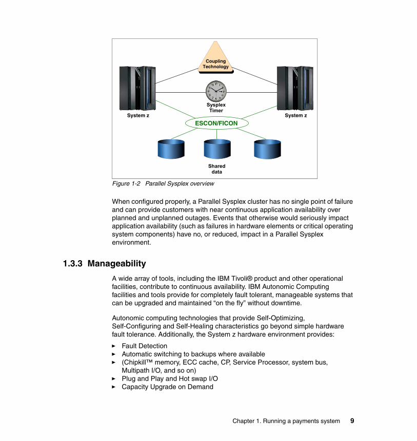
Figure 1-2 Parallel Sysplex overview
When configured properly, a Parallel Sysplex cluster has no single point of failure and can provide customers with near continuous application availability over planned and unplanned outages. Events that otherwise would seriously impact application availability (such as failures in hardware elements or critical operating system components) have no, or reduced, impact in a Parallel Sysplex environment.
1.3.3 Manageability
A wide array of tools, including the IBM Tivoli® product and other operational facilities, contribute to continuous availability. IBM Autonomic Computing facilities and tools provide for completely fault tolerant, manageable systems that can be upgraded and maintained “on the fly” without downtime.
Autonomic computing technologies that provide Self-Optimizing, Self-Configuring and Self-Healing characteristics go beyond simple hardware fault tolerance. Additionally, the System z hardware environment provides:
� Fault Detection� Automatic switching to backups where available � (Chipkill™ memory, ECC cache, CP, Service Processor, system bus,
Multipath I/O, and so on)� Plug and Play and Hot swap I/O � Capacity Upgrade on Demand
CouplingTechnology
Shared data
Sysplex Timer
ESCON/FICONSystem z System z
Chapter 1. Running a payments system 9

The combination of tools, facilities, hardware design, and software architecture provides 100% uptime.
1.3.4 Security
On March 14, 2003, IBM eServer™ zSeries 900 was the first server to be awarded EAL5 security certification. The System z architecture is designed to prevent the flow of information among logical partitions on a system, thus helping to ensure that confidential or sensitive data remains within the boundaries of a single partition.
On February 15, 2005, IBM and Novell announced that SUSE Linux Enterprise Server 9 successfully completed a Common Criteria (CC) evaluation to achieve a new level of security certification (CAPP/EAL4+). IBM and Novell also achieved US DoD Common Operating Environment (COE) compliance, a Defense Information Systems Agency requirement for military computing products.
On March 2, 2006, z/OS V1.7 with the RACF® optional feature achieved EAL4+ for Controlled Access Protection Profile (CAPP) and Labeled Security Protection Profile (LSPP). This prestigious certification assures customers that z/OS V1.7 has gone through an extensive and rigorous testing process and conforms to standards sanctioned by the International Standards Organization.
1.3.5 Expandability
The Parallel Sysplex environment can scale near linearly from 2 to 32 systems. This can be a mix of any servers that support the Parallel Sysplex environment. The aggregated capacity of this configuration meets every processing requirement known today.
The Capacity Upgrade on Demand (CUoD) capability allows you to nondisruptively add one or more Central Processors (CPs), Internal Coupling Facilities (ICFs), zSeries Application Assist Processor (zAAP), and Integrated Facility for Linux (IFLs) to increase server resources when they are needed, without incurring downtime.
Capacity Upgrade on Demand can quickly add processors up to the maximum number of available inactive engines. Also, additional books (up to a maximum of four in total) can be installed concurrently, providing additional processing units and memory capacity to a z9-109 server.
In addition, the new Enhanced Book Availability function also enables a memory upgrade to an installed z9-109 book in a multibook server. This can provide customers with the capacity for much needed dynamic growth in an unpredictable ATM/EFT world.
10 A Guide to Using ACI Worldwide’s BASE24-es on z/OS
The CUoD functions are:
� Nondisruptive CP, ICF, IFL, and zAAP upgrades� Dynamic upgrade of all I/O cards in the I/O Cage� Dynamic upgrade of memory
1.3.6 Dynamic workload balancing
To end users and business applications, the entire Parallel Sysplex cluster can be seen as a single logical resource. Just as work can be dynamically distributed across the individual processors within a single SMP server, so too can work be directed to any node in a Parallel Sysplex cluster having available capacity. This avoids the need to partition data or applications among individual nodes in the cluster, or to replicate databases across multiple servers.
Chapter 1. Running a payments system 11

12 A Guide to Using ACI Worldwide’s BASE24-es on z/OS
Chapter 2. Introducing BASE24-es
At the heart of any payments network is a payment engine. The payment engine must acquire, switch, route and authorize transactions from a variety of sources. ACI Worldwide is a leader in mission-critical e-payment software, offering solutions to manage transactions from the point of access to settlement. BASE24-es® is part of the ACI Payments Framework, a broad suite of products developed by ACI.
In this chapter we describe the BASE24-es product and its functions and features.
2
© Copyright IBM Corp. 2006. All rights reserved. 13
2.1 BASE24-es
The ACI BASE24-es product represents the latest in payment engine technology, offering robust features and functions to the financial payments industry.
2.1.1 Consumer transaction support
BASE24-es provides comprehensive support for consumer e-payment transactions initiated by a variety of transaction instruments that include credit, debit and chip cards.
As the payment industry evolves and new instruments emerge (for example, customer ID, mobile telephone numbers), the flexible nature of its architecture enables BASE24-es to easily adapt to provide continued value.
Today, BASE24-es supports a comprehensive cardholder and administrative transaction set that can be accessed from any appropriate delivery channel. Administrative transactions are also supported for settlement and reconciliation purposes.
BASE24-es can be configured to maintain card and associated account information. Authorization logic can be scripted to perform a variety of tasks including check current status of the card, compare cardholder use against limit profiles, determine whether the transaction is allowed based on a number of configurable options, and more. In addition, BASE24-es can provide alternate routing or stand-in authorization if a configured primary external authorizer becomes unavailable.
2.1.2 Transaction switching and routing
BASE24-es provides a highly flexible routing structure for transactions. This flexibility not only routes transactions to the appropriate network, card association, processor or internal system for authorization, but it also helps users gain lower interchange charges by factoring in the total path when determining the authorization destination.
Transactions are routed based on a combination of the following:
� Source Profile� Destination Profile� Transaction Type� Account Type 1 (FROM account type)� Account Type 2 (TO account type)� Method of consumer authentication (PIN present, chip card, and so on)
14 A Guide to Using ACI Worldwide’s BASE24-es on z/OS
This flexibility in transaction routing accommodates different account types that may reside on different systems, as well as different platforms. Users can customize their transaction processing at various stages in the transaction life cycle, including:
� Pre-screening before transactions are sent to an external authorizer
� Defining the processing steps for real time internal authorization
� Defining the processing steps for stand-in authorization
� Specifying the destination of advice messages following authorization
� Specifying how the database should be impacted during the post-authorization process
2.1.3 Flexible authorization
BASE24-es supports consumer authentication and authorization processing via a powerful scripting engine. The scripting engine enables organizations to control and define application logic without having to modify product source code.
Using an interpreted scripting language with JavaScript™-like syntax, BASE24-es allows users to create a variety of authorization scripts to tailor the authorization logic to meet specific business requirements or service agreements. Organizations can decide what data is used in the authorization process and when the data is used, regardless of whether the data is part of the transaction or from an alternative source.
ACI provides a set of sample scripts that cover the basic positive, negative or usage-based authorization processes. This flexibility shortens the time needed to develop new products and services or accommodate changes requested by the business department of an organization. Separating the business logic (in scripts) from the product source code also facilitates script compatibility with future releases.
Users can choose what level of authorization should be performed on BASE24-es. This can range from full authorization using a card, limit, account and balance information, to handling pre-screening before using a host for authorization, to just providing a stand-in capability using negative card data. All limits are user-defined to provide full flexibility in controlling use of the cards and accounts.
2.1.4 Integrated consumer data
The component architecture of BASE24-es is designed for flexibility to leverage consumer data resident in external systems and databases. Users can develop
Chapter 2. Introducing BASE24-es 15
components that expose consumer data to the scripting engine to allow more intuitive authorization functionality. This consumer data can be held in customer relationship management (CRM) systems, fraud management systems, customer information files, core banking systems and other applications.
By exposing more consumer information to the authorization process, organizations can improve consumer relationships by approving transactions based on more comprehensive consumer information. They can also intelligently manage risk by denying transactions based on certain risk factors.
2.1.5 Traditional and emerging delivery channels
In addition to support for traditional delivery channels, including ATM and point-of-sale (POS), BASE24-es can process payments initiated through Internet shopping networks, personal digital assistants (PDAs), mobile telephones, Web ATMs, and home banking and branch systems. BASE24-es offers a powerful, flexible foundation for delivering common services across multiple consumer access channels, computer systems and databases.
Through the use of XML- and ISO-based interface standards and other industry-specific formats, transaction services can be exposed to any channel. Thus, BASE24-es can provide a single point of access across an enterprise for the service of consumer payments, eliminating the costs of maintaining multiple service points.
2.1.6 Reliable security infrastructure
Organizations’ transaction security requirements can vary greatly depending on the environment. An organization typically requires an integrated system of software, industry-standard hardware, and procedures to properly implement financial transaction security.
BASE24-es is designed to be flexible in its transaction security support and to provide a range of hardware options. The application addresses the diverse needs of large-scale transaction processing systems where the originator of a transaction may operate under an entirely different transaction security scheme than the authorizer. Regardless of the origin or destination of payments, BASE24-es meets the current industry requirements for security, including Triple DES and EMV support.
BASE24-es operates in a network environment where sensitive data, such as the personal identification number (PIN), is secured via encryption, and the system provides cryptographic functions such as PIN encryption, PIN verification, message authentication, chip authentication and card verification using interfaces to external hardware security modules (HSMs).
16 A Guide to Using ACI Worldwide’s BASE24-es on z/OS
2.1.7 Intuitive graphical user interface
The ACI user interface presents a task-oriented view of the application for multiple users ranging from business to technical to administrative, and it incorporates graphical elements such as hyperlinks, buttons and pull-down menus. Users can also choose to display text labels in their local language to accommodate adaptation into their environment. Integrated help at the window level and the field level minimizes the need for extensive user training, while streamlining business processes and providing greater flexibility.
Written in Java and C++ and using XML message formats, the ACI user interface provides a flexible operating environment that is used by multiple ACI applications. A security administrator configures access permissions through the ACI user interface where a user security and user audit environment are shared by all ACI applications.
2.1.8 Scriptable extracts and reports
The BASE24-es scripting engine gives users added flexibility and control over the reporting and extracting of financial transaction data. In an area where customization is virtually required to meet integration needs, the scripting feature allows real time definition of essential and ad hoc reports, as well as user-defined file layouts to serve as input to existing batch processes or reporting tools.
2.1.9 National switch and international card scheme interfaces
BASE24-es incorporates off-the-shelf support for a range of international card scheme interfaces, including Visa, MasterCard and American Express, as well as many national switch interfaces. These interfaces are built using a framework methodology covering ISO 8583 (1987), ISO 8583 (1993) and XML standards. This methodology makes use of “inheritance” to facilitate reusability of components and allows new interfaces to be built quickly by either ACI or the customer organization.
2.2 Architecture
ACI uses an object-oriented design and development style to implement its Enterprise Services architecture of BASE24-es. This architecture helps reduce impacts associated with extending the core product code. The use of object-oriented programming languages, such as C++ and Java, enhance the extensibility of BASE24-es solutions and minimize time-to-market for new products and services. By extending integration flexibility, BASE24-es allows access to more customer information.
Chapter 2. Introducing BASE24-es 17
BASE24-es software components use this architecture to create flexible business services that allow users to quickly develop and deploy new products and deliver enhanced customer service. The components are organized according to the function they perform to support processing for the required business services. Each business component performs a specific type of processing (that is, authorization or routing) or controls a specific part of the file system (for example, account or customer).
The architecture of BASE24-es is designed for multiple platform configurations. The platform is defined as the hardware, operating system, middleware, and file system. However, platform-specific processing is isolated into specific components to allow the rest of the application to be common across all platforms.
BASE24-es software components are organized according to the function they perform, as described here:
� Adaptors manage the information exchanged between the end user and the business components. Adaptors can be designed to communicate with any acquiring or issuing entity, including Internet portals, hardware devices, service providers or interchanges (Visa, MasterCard, and so on), and in-house systems.
� Business components perform the processing required for the business services offered. Each business component performs a specific type of processing (that is, authorization, routing) or controls a specific part of the file system (for example, prefix, perusal).
� Foundation components provide information and processing required by business components regardless of the software module. These are the basic building blocks for any application. For example, the time component obtains the current system time in the format needed by the application. When any business component needs the system time, it obtains it from this foundation component.
� Platform-specific components insulate the application from changes in the operating system, middleware, and data structure. For example, processing performed by the time component differs across platforms.
18 A Guide to Using ACI Worldwide’s BASE24-es on z/OS
2.3 Operability
BASE24-es supports high volume, high availability, 24/7 operability through a scalable, high available software architecture that runs on a variety of platforms, as explained here:
� Flexible journal configuration and settlement cutover
This allows for 24/7 cutover processing and uninterrupted processing across separate time frames.
� Implement new business logic without downtime
Code and file system changes that affect configuration do not require a system restart.
� Hardware resilience
The system and data access layers take advantage of each platform’s failover processing capabilities, all with the same set of application code.
� Consistent processing cost
The asynchronous messaging model of BASE24-es provides a consistent per transaction processing cost regardless of the transaction volume, which allows the application to grow as needed with a predictable hardware requirement.
2.4 Scripting component
The BASE24-es scripting facility gives organizations a powerful JavaScript-like syntax to allow modification of application logic without having to modify the source code. The application uses these scripts to create journal perusal queries, define journal extract and reporting requirements, and as part of the authorization process.
Scripts are maintained and compiled through the user interface. Users can display a script repository that shows all scripts available for use by BASE24-es. A script editor allows the user to add, edit, delete and compile scripts through the user interface. During the compile process, scripts are checked for syntax errors and saved on the BASE24-es system. Rather than compiling into machine code, these scripts are ordered into a list of serial instructions that the script engine may interpret in real time during transaction processing.
Compiled scripts are loaded into memory where they can be retrieved for execution during transaction processing. If a change must be made to script logic, then the script can be updated, recompiled and placed back into use without ever taking the affected programs out of service.
Chapter 2. Introducing BASE24-es 19
Scripts have access to data from multiple sources; the primary source is from transaction data elements. Application files for authorization are also available to the script facility, and these include card file, limits file, usage accumulation file, account with balance file and pre-authorization file. For greater decision-making flexibility, access to additional customer information can be obtained through custom written components that “expose” the proprietary structure of a customer’s file to the script. These custom files may be core banking system files, ACI or other third-party card management systems, or a variety of other sources.
A single script can contain all of the tasks that BASE24-es must perform to authorize a transaction. The tasks can also be split into multiple scripts that are organized in a hierarchical structure.
Because of the component-based design of the application and the scripting language, scripts implemented by the user may not need to be modified when a new release of the application becomes available, allowing users to easily upgrade to new releases of the product. If a user plans to take advantage of new functionality from within the script, then changes will be required.
2.5 The user interface
The BASE24-es user interface employs Java, C++ and XML technologies, providing the user interfaces needed to manage all components of the application.
With the system’s built-in user security feature, users are assigned roles that grant them permission to specific functions and tasks associated with various windows. Users are authenticated during the logon process, thereby minimizing the risk associated with unauthorized users gaining access to functions they are not permitted to perform.
The user audit function is responsible for maintaining a secure audit database where all file maintenance transactions and modifications to the user security database are recorded. Before and after images of the affected record will be logged wherever appropriate.
The user interface design incorporates the flexibility for users to alter the layout and wording on the desktop to meet individual organization needs. All text and positional information is maintained in configuration files, so adapting the user interface without altering the product code is particularly easy. This structure also incorporates multi-language capability.
20 A Guide to Using ACI Worldwide’s BASE24-es on z/OS
2.6 Rich functionality
BASE24-es provides full functionality to support payment transactions across multiple channels. The software is parameter-driven, allowing users to configure a system that will meet their unique business requirements. ACI’s product investment strategy accommodates periodic new releases of software providing support for both regulatory changes as well as new trends in electronic delivery.
2.7 Platform independence
BASE24-es supports a broad range of computing environments, allowing customers to operate ACI’s best-of-breed software on their choice of industry-standard platforms. BASE24-es operates on a variety of HP, IBM and Sun™ servers. On each platform, our ACI software takes advantage of the best in systems software for reliability, availability and high-performance throughput.
2.8 Flexible architecture
Since the design of BASE24-es includes support for scripting, there is little need for customer technical staff to have knowledge of the core languages of the application. A working knowledge of JavaScript programming methods will prepare an experienced programmer for maintenance and creation of the business logic necessary to meet the institution’s authorization processing needs.
Because the BASE24-es application is component-based, ACI customers have the freedom to develop components in-house, which extends product functionality. To accomplish this task, some basic skills concepts are required as outlined below:
� UML (Unified Modeling Language)� C++� Java
2.9 The ACI Payments Framework
ACI offers mission-critical e-payment software solutions to manage transactions from the point of access to settlement. BASE24-es is part of the ACI Payments Framework, a broad suite of products developed by ACI. The ACI Payments Framework includes software to enable transaction processing through evolving
Chapter 2. Introducing BASE24-es 21
Internet and wireless channels as well as traditional ATM and POS channels. ACI solutions process transactions in real time and automate the back-office functions associated with settlement, dispute processing, fraud detection and account service.
22 A Guide to Using ACI Worldwide’s BASE24-es on z/OS

Chapter 3. System z and z/OS
In this chapter we describe the features and the quality of service provided by the IBM System z platform and the z/OS operating system.
3
© Copyright IBM Corp. 2006. All rights reserved. 23
3.1 How z/OS addresses non-functional requirementsIn this section we describe the traditional strengths of the mainframe. We focus on the qualities that the mainframe provides, thereby addressing the relevant non-functional requirements of most mission-critical IT systems.
3.1.1 BackgroundFor more than 40 years, IBM mainframes have successfully run the core IT systems of many mid-size, large, and very large enterprises. Over this period, IBM has consistently invested in the evolution of the mainframe’s unparalleled technology. Mainframes have incorporated new technologies and computing models, ranging from the centralized model to computing to the Web model, and from assembler and COBOL languages to Java.
IBM mainframes have become the computing industry benchmark. They are used by thousands of enterprises worldwide, with trillions of dollars invested in applications and skills. The platform hosts a large portion of the total business transactions and data in the world, providing 24x7 availability and other unique qualities.
IBM mainframes run five different operating systems, consisting of z/OS, z/VM®, z/VSE™, z/TPF and Linux on System Z. In the following section we focus on the z/OS operating system, the flagship mainframe operating system.
3.1.2 Traditional z/OS strengthsThe generally recognized strengths of z/OS fit into a number of broad categories:
� Centralized computing model� Security� Manageability� Virtualization and workload management� Reliability� Scalability� Availability� Communications and I/O� Transaction processing� Batch processing
To provide these, the z/OS operating system includes a comprehensive set of capabilities and tools out of the box. z/OS provides its unique Quality of Service (QoS) in combination with System z hardware and Parallel Sysplex capabilities. In the following sections we discuss each of these areas in more detail.
24 A Guide to Using ACI Worldwide’s BASE24-es on z/OS

3.1.3 Centralized computing model We define a computing model as a structure that organizes the way communication and sharing occurs. A computing model describes the topology of interconnected computer resources, as well as how users access these resources.
In the history of commercial computing, we have seen three major computing models: centralized, client/server, and network computing, as described here:
� The centralized model is characterized by a single (or a few) large computing nodes.
In this model, a variety of applications are hosted on the nodes, ranging from tens to several hundred or even thousands of applications. The applications all share the same computing resources such as memory, CPU, and disk and tape storage. All users are directly connected to this system.
� The client/server model spreads computing resources over a large number of distributed computing nodes that do not share the same resources.
In this model, each computing node typically runs a single (or just a few) applications, and the applications communicate over the network. The objective of this model was to offload processing from the central computers.
� The network computing model (also known as the Web model) allows users to connect to applications using a Web browser, which is independent of a particular operating system or hardware.
All data, business logic, and applications are brought back to servers, and only the information required for display is sent to the user device.
Small applications (or applets) can be downloaded from the server and run in the local memory of the terminal to improve functionality or performance. The Web model allows users to connect to applications from anywhere over the Internet.
Figure 3-1 on page 26 offers a simplified view of these computing models.
Chapter 3. System z and z/OS 25
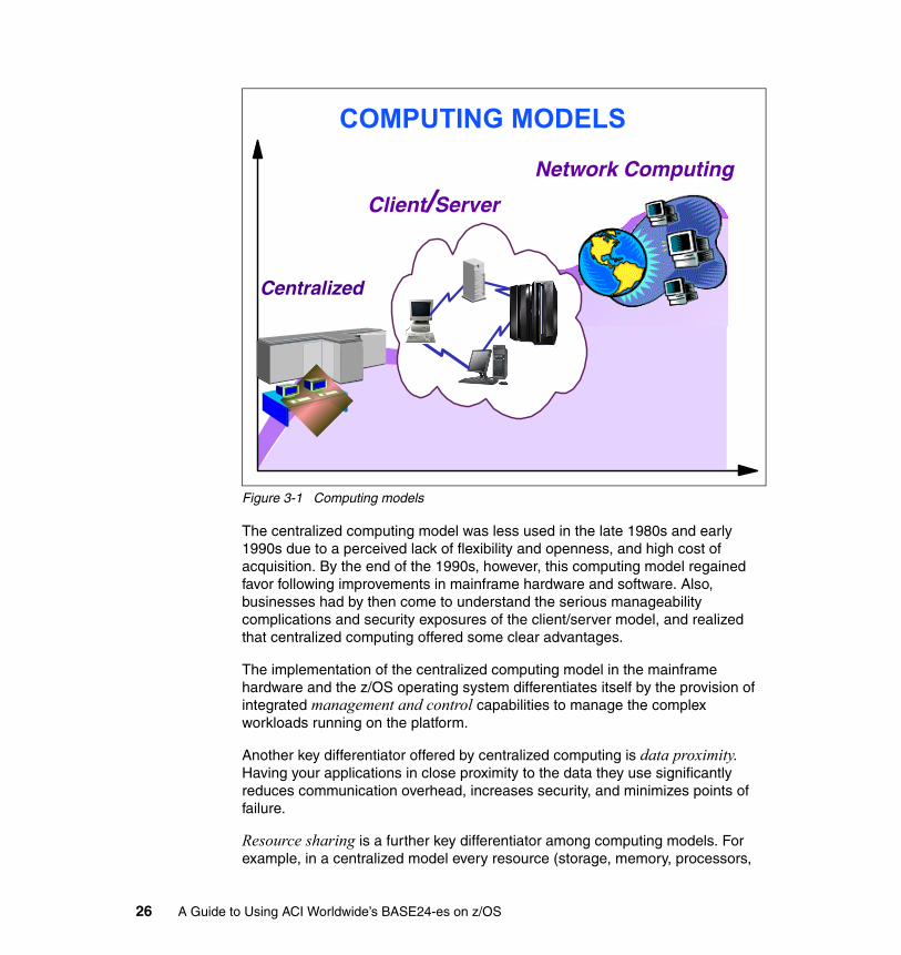
Figure 3-1 Computing models
The centralized computing model was less used in the late 1980s and early 1990s due to a perceived lack of flexibility and openness, and high cost of acquisition. By the end of the 1990s, however, this computing model regained favor following improvements in mainframe hardware and software. Also, businesses had by then come to understand the serious manageability complications and security exposures of the client/server model, and realized that centralized computing offered some clear advantages.
The implementation of the centralized computing model in the mainframe hardware and the z/OS operating system differentiates itself by the provision of integrated management and control capabilities to manage the complex workloads running on the platform.
Another key differentiator offered by centralized computing is data proximity. Having your applications in close proximity to the data they use significantly reduces communication overhead, increases security, and minimizes points of failure.
Resource sharing is a further key differentiator among computing models. For example, in a centralized model every resource (storage, memory, processors,
Centralized
Network Computing
Client/Server
COMPUTING MODELS
26 A Guide to Using ACI Worldwide’s BASE24-es on z/OS
I/O channels, and so on) is shared between the different applications. This leads to overall better utilization of those resources and less idle time. In a distributed model with dedicated resources, efficiency is significantly lower and idle time higher.
Partitioning and Parallel SysplexCentralizing all components on a single system does not imply that mainframe computing is limited to a single machine or to a single operating system. On the contrary, mainframes have the capability of being partitioned on up to 60 logical partitions (LPARs), and each LPAR has the ability to run one of the five z operating systems. There are also management tools and resource sharing at the machine level, and at the operating system level.
The z/OS Operating System allows you to create a cluster of up to 32 systems; this is known as Parallel Sysplex. In Parallel Sysplex, a “system” can be a full machine or just an LPAR. Most computing platforms today offer clustering capabilities. Parallel Sysplex, however, is a completely different kind of clustering solution because it can share every resource among the elements in the cluster, and also dynamically reconfigure, add, or remove resources.
Notably, z/OS also allows all members in a cluster to share all data, even up to the record level. In contrast, other cluster implementations allow you to partition data among the elements of the cluster, and each system can access just the data attached to it.
Parallel Sysplex also provides significant network optimizations for communication across its cluster members. After a client request reaches the Sysplex Distributor there is no more external network traffic required; all traffic flows over the System z hardware. As a consequence, network latency is kept to a minimum and the typical network issues you normally see in a physical decentralized infrastructure are inherently absent.
Even when the Parallel Sysplex is physically spread over several different machines, the communication between them flows over high speed fiber optic connections managed by the Cross Coupling Facility (XCF), a specific protocol for those connections with a magnitude of GigaBytes of transfer rate. Within a physical machine, communication between z/OS images is accomplished through memory-to-memory, and there is no network protocol faster than that.
Securityz/OS provides deep security integration, from the application level down to the operating system level and the hardware. In this section we highlight a number of major functions in z/OS.
Chapter 3. System z and z/OS 27

Centralized security Approximately 30 years ago IBM developed the Resource Access Control Facility (RACF) to provide centralized security functions such as user identification and authentication, resource access control, and auditing for both the operating system and applications running on the system. As a next step, to improve the usability of the system's security interfaces and thus encourage more applications to use consistent system-level security rather than implement their own separate security mechanisms, IBM implemented the System Authorization Facility (SAF) within the MVS™ operating system. SAF combined the various security function invocations into a single extensible security mechanism.
This new security structure provided several benefits to encourage use by application programs and components of the operating system itself. Most recently, IBM has again modified SAF to provide additional security interfaces for the UNIX environment on z/OS.
With the introduction of the System Authorization Facility suite of services, a centralized point was created within the operating system infrastructure through which both operating system components and applications could invoke the services of the z/OS resident security manager.
Auditing and loggingA very important feature of a centralized authentication and access control mechanism is the ability to record and analyze security information. The audit data is essential for ensuring that the client’s installation security policy is being followed. The RACF option of the z/OS Security Server provides multiple ways to specify what security-relevant events are recorded in the audit stream, and how that information is reduced and analyzed. RACF provides a wide variety of capabilities and tools to the auditor for data analysis.
AccountabilityAccountability in z/OS is achieved by a combination of user authentication and the ability to propagate a user’s credentials throughout the application.
The System Management Facility (SMF) interface is designed for collecting performance and accounting information. z/OS will collect all accounting and performance data and present this back to the installation through RMF™ and SMF records. These records can be analyzed and aggregated in performance and capacity reports, but can also be used as a base for security analysis and accounting policies.
CryptographyThe System z hardware has two distinctly different cryptographic hardware engines that are supported under z/OS; the CMOS (Complementary Metal Oxide
28 A Guide to Using ACI Worldwide’s BASE24-es on z/OS
Semiconductor) Cryptographic Coprocessor and the newer PCI (Peripheral Component Interface) Cryptographic Coprocessor (PCICC). The PCICC
provides the capability for rapid response to client requirements that was sometimes difficult to achieve with the CMOS Cryptographic Coprocessor alone. For further details about this topic, refer to 4.2.10, “AOR architecture” on page 56.
Network securityNetworking and communications security on z/OS is provided by the Communications Server element of z/OS. The Communications Server provides networking and communication services for accessing z/OS applications over both SNA and TCP/IP networks.
Firewall Technologies within the Communications Server provide the network-level protections. The Communications Server provides a further, optional layer of protection by supporting multiple TCP/IP “stacks” which can allow clients to configure TCP/IP communications in a way that segregates the external (public) traffic from the internal traffic used in the private network. Thus, the z/OS Firewall Technologies can provide extra protection for applications using the stack that handles the external communications traffic.
Furthermore, the Firewall Technologies include packet filtering to limit the kind of network requests that can reach a machine, proxy and SOCKS servers to control TCP/IP connectivity, Domain Name Services (DNS), encryption of IP traffic (IP tunnels, or Virtual Private Networks (VPN)) to allow private communication over the public network. Other security features provided by z/OS and the Communications Server include LDAP, PKI, Kerberos, and openSSH.
ManageabilityThe z/OS operating system has been designed to manage multiple workloads in a single system image. This design has, from the beginning, put the requirements on the operating system to provide the means to manage these complex environments. As a consequence, over the years z/OS has become equipped with an extensive set of management tools for managing and controlling thousands of complex simultaneously running applications, comprising batch and online components, databases, transaction managers and so on.
The management tools included in z/OS have become a very mature set of system management and automation software. Clients over the years have based their sophisticated procedures and automation scenarios on this software.
Chapter 3. System z and z/OS 29
These tools include:
� SAF (discussed in “Security” on page 27) is the security interface built into the operating system, and RACF is provided for security administration and management.
� SMF and RMF are used for resource management, performance management, capacity planning capabilities and logging of system and middleware events.
� SMP/E is used for product installation and maintenance.
� DFSMS provides data management software that automatically manages data from creation to expiration. DFSMS provides allocation control for availability and performance, backup/recovery and disaster recovery services, space management, tape management, and reporting and simulation for performance and configuration tuning.
� SDSF provides the abilities to monitor, manage, and control the z/OS sysplex.
� System Automation provides the capabilities to increase application availability through policy-based self-healing, and to automate z/OS Input/Output, processor and systems operations.
� Tivoli Workload Scheduler (TWS) provides functions to automate, plan, and control the processing of an enterprise's entire production workload.
Virtualization and workload managementWhy is System z the most trusted platform for core enterprise systems and applications? One of the reasons for this is virtualization. Unlike most other computer systems, the IBM Mainframe is designed from the silicon chip and up for virtualization. By comparison, RISC and Intel® chips are architected to meet computational benchmarks. What they gain in the processing of instructions, they lose in task switching, error handling, data movement and input-output operations. IBM mainframes create a virtual environment, not only for existing and new CICS, IMS™, DB2® and Batch workloads, but also for workloads such as Java (J2EE™) applications, Linux, UNIX and GRID applications. This means that an enterprise can run its entire enterprise server workload within a virtual mainframe environment.
Mainframes typically meet their service requirements at 80% to 100% utilization levels, and the varying nature of application workloads means that a shared infrastructure is more efficient than a set of dedicated servers. Peak mainframe workloads are dealt with by reducing the allocation of resources to lower-priority background tasks and through dynamic reallocation of resources.
The virtualization capabilities of IBM mainframes are diverse (see Figure 3-2 on page 31).
30 A Guide to Using ACI Worldwide’s BASE24-es on z/OS
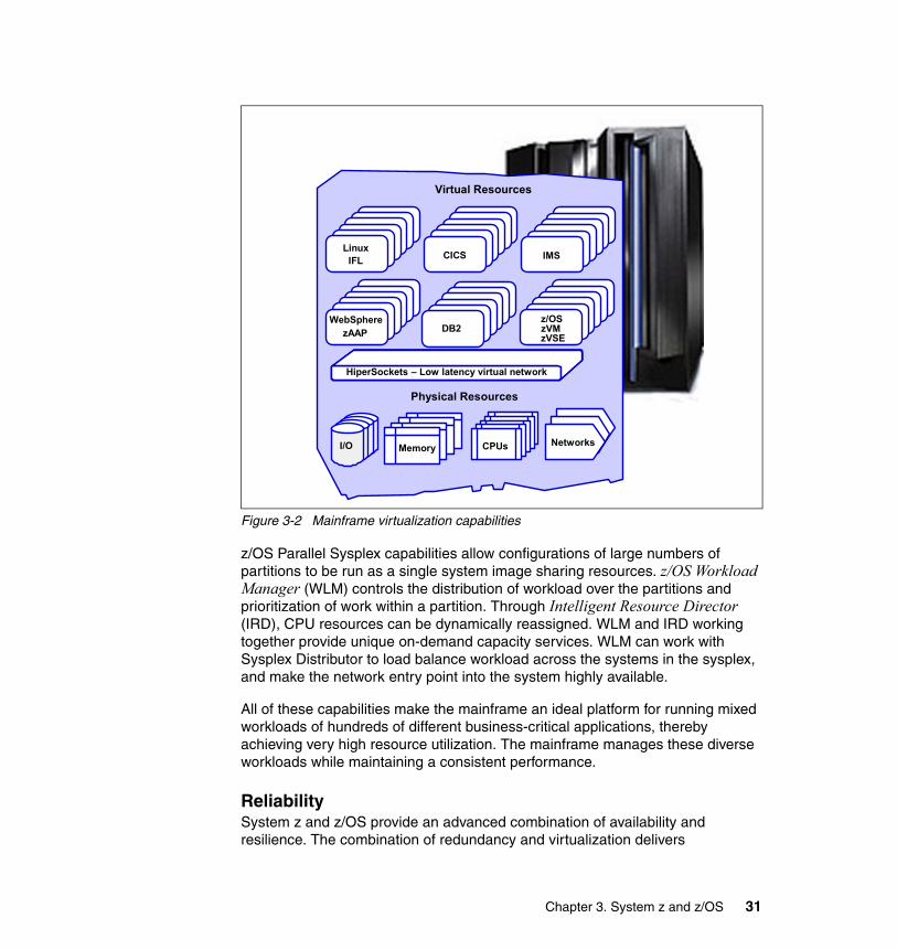
Figure 3-2 Mainframe virtualization capabilities
z/OS Parallel Sysplex capabilities allow configurations of large numbers of partitions to be run as a single system image sharing resources. z/OS Workload Manager (WLM) controls the distribution of workload over the partitions and prioritization of work within a partition. Through Intelligent Resource Director (IRD), CPU resources can be dynamically reassigned. WLM and IRD working together provide unique on-demand capacity services. WLM can work with Sysplex Distributor to load balance workload across the systems in the sysplex, and make the network entry point into the system highly available.
All of these capabilities make the mainframe an ideal platform for running mixed workloads of hundreds of different business-critical applications, thereby achieving very high resource utilization. The mainframe manages these diverse workloads while maintaining a consistent performance.
ReliabilitySystem z and z/OS provide an advanced combination of availability and resilience. The combination of redundancy and virtualization delivers
Physical Resources
Virtual Resources
HiperSockets – Low latency virtual network
WebSpherezAAP DB2
z/OSzVMzVSE
HiperSockets – Low latency virtual networkHiperSockets – Low latency virtual network
LinuxIFL
I/O
MemoryMemoryMemoryMemoryMemory CPUs Networks
CICS IMS
Chapter 3. System z and z/OS 31
extraordinary levels of application availability and recoverability. IBM mainframe architecture helps to protect end users from hardware and software failures. If an application fails, its workload can be picked up by a backup of the same application, running on the same physical hardware. On a more granular level, z/OS uses a feature called Automatic Restart Manager (ARM) for automatic recovery and restart of services and transactions based on predefined polices.
IBM mainframe software is designed for transactional integrity with system-wide two-phase commit. That means that a client’s application data is recoverable, even when hardware and software failures occur. z/OS provides a special set of services for this activity, called Resource Recovery Services (RRS), which are commonly used by middleware solutions, but which can also be used in custom applications, as the APIs are public. When resources in the commit scope are all on z/OS, RRS can provide two-phase commit functionality without the need for distributed transaction technologies such as XA.
Mainframe workloads can be shared by systems running up to 100 km apart, allowing for smooth disaster recovery procedures. And when the time comes to add system capacity, or replace a failed hardware module, those hardware changes can be done without interrupting customer service. Some mainframes run uninterrupted for years, adapting to changing needs, workloads, and applications while continuously in production.
System z hardware provides a solution with no single point of failure. There is redundancy within the power supply and cooling, an inside battery for backup, and built-in spare processors and memory. Another hardware advantage is the ability to perform a hardware upgrade or hardware maintenance without taking the machine down.
ScalabilitySystem z hardware can be scaled up vertically to a maximum of 54 CPUs at this time. The z/OS Parallel Sysplex configuration provides additional horizontal scalability. A sysplex can be a cluster of up to 64 z/OS images in different partitions on different System z machines (possibly geographically dispersed), with full data sharing and high availability and recovery.
The machines participating in a Parallel Sysplex can be physically dispersed up to 100 km distance each to the other, which gives the capability of having a physically decentralized infrastructure being logically centralized.
In z/OS, the horizontal scalability is not limited to specific workloads. Any workload can take advantage of the Parallel Sysplex scaling options.
Scalability is fundamental in an on demand world, and the IT infrastructure should be able to scale when business demands more resources. This does not
32 A Guide to Using ACI Worldwide’s BASE24-es on z/OS
necessarily mean a new server or system image must be integrated to the complex in some way or another, as is required on distributed platforms. Mainframes offer more capabilities to scale on demand. Other platforms scale out, while mainframes scale in, as explained here:
� Scaling out means adding resources to a logical system by adding a physical system (or operating system image), thereby increasing the configuration complexity and reducing manageability.
� Scaling in means (automatically) aggregating new resources to the existing infrastructure white-hot increasing its complexity, without demanding redesign of data bases, application patterns, network traffic and so on and without the need to bring the system down.
This is another mainframe differentiator, by design. For instance, you can add new processors, new storage, or reconfigure partitions, without any impact on applications, data, and existing infrastructure.
Another key performance and scalability benefit of mainframes is provided by the HiperSockets™ virtual TCP/IP network, which eliminates network delays between applications and subsystems running within a mainframe.
AvailabilitySystem z has many components to address availability, as well as z/OS.
Parallel Sysplex, the clustering solution for the z/OS environment, provides both scalability and availability. With Parallel Sysplex, a failure of one image in the cluster does not affect any other image. And any specific transaction running on the failed image can be fully dispatched and recovered in any other image, thus making use of the full data sharing architecture.
For higher availability and disaster recovery purposes, a Parallel Sysplex can be configured in a Geographically Dispersed Parallel Sysplex™ (GDPS®) mode. There are two GDPS modes:
� GDPS/PPRC
GDPS/PPRC is a configuration in which a Parallel Sysplex is distributed across two sites, connected together up to 100 km, with data synchronized and shared continuously.
One site (part of the sysplex) acts as a primary, and the second site acts as a secondary, in stand-by mode. GDPS controls and automates a full swap to the backup site in case of failures.
� GDPS/XRC
GDPS/XRC is a configuration in which the distance between sites can be more than 100 km, theoretically without limitation. In GDPS/XRC, the sysplex
Chapter 3. System z and z/OS 33

does not span both sites. Instead, a full system image is swapped to the alternate site in an emergency situation.
Both modes use HiperSwap, which allows you to activate replicated data in the disaster recovery site without application outage.
Figure 3-3 illustrates a simplified view of z/OS continuous availability.
Figure 3-3 z/OS continuous availability
The System z and z/OS availability features are:
� Unique mainframe clustering technology for maximum up-time (Parallel Sysplex)
� The ability to deploy participating nodes in the sysplex cluster remotely (Geographically Dispersed Parallel Sysplex)
� The ability to recover virtual Linux servers running remotely (xDR)
� Replicate data real-time at remote locations (PPRC)
Communications and I/OOver the past decade, focus has shifted from SNA networks and applications to TCP/IP and Internet technologies. The TCP/IP protocol suite has become a de facto standard for transmitting data over networks. But SNA is still used
121
23
45
67
89
1011
12 12
34
5678
910
11 1212
34
5 6 789
1011
Single System GDPSParallel Sysplex
1 to 32 systems Site 1 Site 2
Built-in RedundancyCapacity Upgrade on DemandCapacity BackupHot Pluggable I/O
Addresses Planned/Unplanned HW and SW Outages Flexible, Nondisruptive Growth
Capacity beyond largest CPCScales better than SMPs
Dynamic Workload/Resource Management
Addresses Site Failure Maintenance Sync/Async Data Mirroring
Eliminates tape/disk SPOFNo/Some data loss
Application-Independent
34 A Guide to Using ACI Worldwide’s BASE24-es on z/OS
extensively in banks and other financial transaction networks. In some cases, SNA application traffic now runs over IP-based networks using Data Link Switching (DLSw). In other cases, applications have been changed, and processes reengineered, using TCP/IP rather than SNA.
For some organizations, the network traffic that traverses IBM SNA communication controllers has declined to the point where it is in the business interest to find functional alternatives for the remaining uses of these controllers by consolidating and possibly eliminating the controllers from the networking environments.
Estimates are that the current use of TCP/IP in the EFT, ATM, and POS environments is more than 70% and rapidly increasing, but there are still a significant percentage of ATMs on SNA protocol and some (less than 5%) on X.25 in the POS segment.
BASE24-es supports VTAM®-attached terminals. The BASE24-es CICS VTAM communication handler currently supports SNA LU 0 and 2. Other BASE24-es VTAM protocols are scheduled on individual client business requirements.
Support for SNA on z/OS is provided by the Communication Controller for Linux (CCL). The 3745/3746 SNA communications controller has been withdrawn from the market.
With CCL you can continue using the traditional SNA subarea (INN), NCP boundary (BNN), SNA Network Interconnect (SNI), and X.25 connectivity that are currently supported by the IBM 3745.
Transaction processingTraditionally, the mainframe has offered extremely robust transaction processing, providing thousands of concurrent online users with the ability to retrieve information and make updates. The IBM transaction management solutions on the mainframe have since long been CICS and IMS on the z/OS platform, and TPF as a specialized operating system on the mainframe for airline and financial transactions.
WebSphere Application Server for z/OS was recently added to the family of transaction managers on z/OS. Businesses have invested heavily in the development of transactional applications, and despite efforts to mimic transaction processing on non-mainframe platforms, these solutions have never provided the same scalability and reliability as mainframe transaction processing.
As discussed, the z/OS operating system provides transactional services that are not limited to applications running in one of the transaction managers. Resource
Chapter 3. System z and z/OS 35
Recovery Services (RRS) assures integrity by providing transaction and two-phase commit services to any application that requires those.
Batch processingAnother outstanding capability of the mainframe architecture is the running of batch workloads. In the z/OS environment, dedicated subsystems (JES2 or JES3), in combination with special job scheduling software such as Tivoli Workload Scheduler (TWS), manage batch processing. No other architecture can support batch processing as well as z/OS.
The value of batch processing is often underrated. With the requirement for integrating new applications with existing back-end systems, batch processing becomes ever more important. The IBM mainframe is well-positioned to handle batch processing. Offering the ability to run batch processes written in the Java language making use of zAAP processors, and the ability to access back-end data either on z/OS or any other server, z/OS is a very cost-effective platform for running business-critical batch applications.
Additional capabilities of z/OS z/OS provides a number of facilities that provide unique implementation capabilities for the products running on the z/OS platform. These capabilities significantly increase the Qualities of Service to a level above what can be reached on other platforms, while preserving functionality at the same level, at a minimum.
OpennessVirtualization has provided “openness” to the mainframe, enabling it to run not only the traditional operating systems of z/OS, z/VM, z/TPF and z/VSE, but also to support Linux. Once called “proprietary” technology, the mainframe has adopted open standards technology as well and is as open as any other UNIX-based platform or the Windows platform. There are no limitations on the mainframe in using standards such TCP/IP, HTTP, SOAP and so on.
Today’s mainframe not only supports open standards, but enables and integrates traditional technologies with the new ones. Core business applications, usually running in IMS or CICS, can be integrated with new-style applications using XML and SOAP, thereby bridging the technology landscape and maximizing investments in skill and resources.
Cost-effectivenessCost is one of the most sensitive and complex aspects of any solution analysis. It is sensitive because everyone responsible has a different opinion of what constitutes a reasonable cost. It is complex, because determining the total cost of a solution requires a critical analysis of many factors.
36 A Guide to Using ACI Worldwide’s BASE24-es on z/OS
Major consulting companies have published many studies related to cost comparison among platforms, and delving further into this topic is beyond the scope of this publication. However, in the following sections we offer some points to consider.
TCA and TCO Total Cost of Acquisition (TCA) refers to the buying cost of a certain product. Total Cost of Ownership (TCO) refers to the whole cost involved in a process, and it extends much further than just the buying cost. TCO takes into account all aspects related to a product’s installation, maintenance, personnel and training costs, the required infrastructure, and so on.
Companies often do not distinguish between TCO and TCA, because lack of knowledge or lack of data makes full analysis impossible. Various consulting companies specialized in performing this kind of analysis have published very positive results for the System z platform, considering five years analysis.
Economies of scale Due to its centralized computing model and almost endless scalability, the System z platform provides economies of scale, meaning that you can add new physical resources (CPU, I/O devices, servers) without the need to proportionally expand the existing infrastructure and the number of staff managing it.
People are often the most expensive resource in a business. In the distributed world, for every additional set of servers or pool of storage, the amount of human resource needed will increase. On the System z platform, however, the number of people supporting it is practically flat and only increases when very large chunks of additional infrastructure are added.
As mentioned in “Scalability” on page 32, another key scalability differentiator between the System z platform and distributed platforms is the difference between scale in and scale out. Scalability is a major factor in achieving service level agreements (SLAs). And with the increasing popularity of the Internet and e-business, companies find it difficult to predict when and how often users will access corporate Web sites and demand IT resources. As a result, system and application scalability have became critically important to success in the world of e-business. With System z, stability is accomplished on the same machine (scale in). In contrast, on distributed platforms you need to add new machines (scale out).
An “out-of-the-box” solutionz/OS is not just an operating system. It is a package that encompasses the operating system itself and more than 30 built-in solutions. The full package comes with everything that is required to build a robust IT software infrastructure.
Chapter 3. System z and z/OS 37
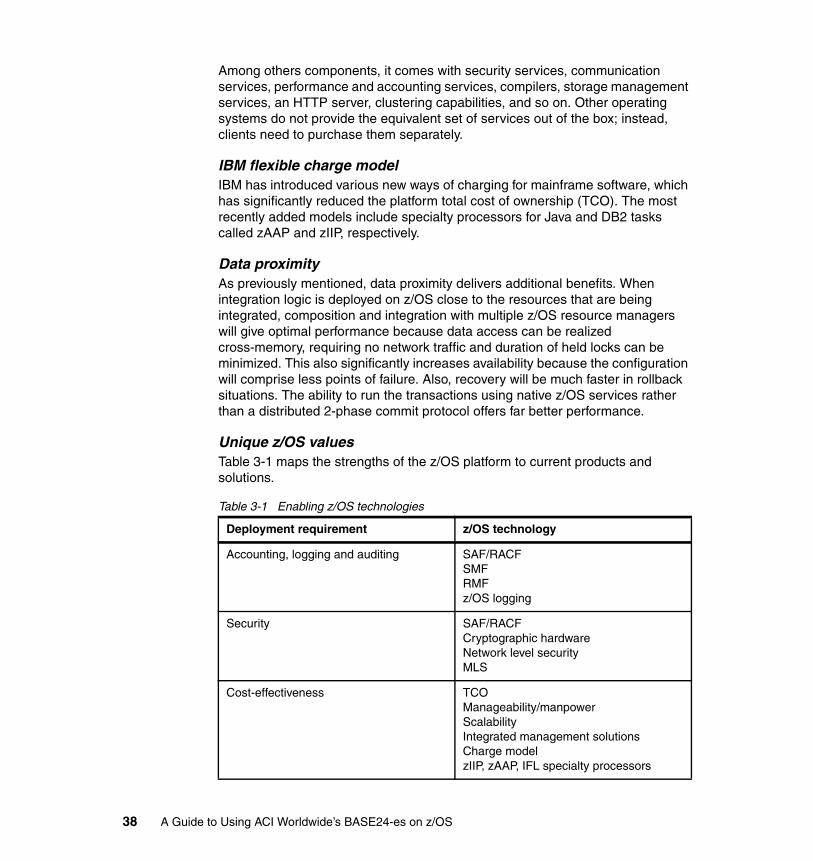
Among others components, it comes with security services, communication services, performance and accounting services, compilers, storage management services, an HTTP server, clustering capabilities, and so on. Other operating systems do not provide the equivalent set of services out of the box; instead, clients need to purchase them separately.
IBM flexible charge modelIBM has introduced various new ways of charging for mainframe software, which has significantly reduced the platform total cost of ownership (TCO). The most recently added models include specialty processors for Java and DB2 tasks called zAAP and zIIP, respectively.
Data proximityAs previously mentioned, data proximity delivers additional benefits. When integration logic is deployed on z/OS close to the resources that are being integrated, composition and integration with multiple z/OS resource managers will give optimal performance because data access can be realized cross-memory, requiring no network traffic and duration of held locks can be minimized. This also significantly increases availability because the configuration will comprise less points of failure. Also, recovery will be much faster in rollback situations. The ability to run the transactions using native z/OS services rather than a distributed 2-phase commit protocol offers far better performance.
Unique z/OS valuesTable 3-1 maps the strengths of the z/OS platform to current products and solutions.
Table 3-1 Enabling z/OS technologies
Deployment requirement z/OS technology
Accounting, logging and auditing SAF/RACFSMFRMFz/OS logging
Security SAF/RACFCryptographic hardwareNetwork level securityMLS
Cost-effectiveness TCOManageability/manpowerScalabilityIntegrated management solutionsCharge modelzIIP, zAAP, IFL specialty processors
38 A Guide to Using ACI Worldwide’s BASE24-es on z/OS
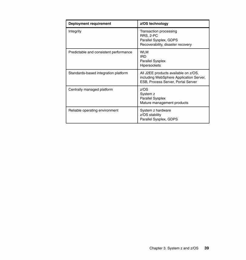
Integrity Transaction processingRRS, 2-PCParallel Sysplex, GDPSRecoverability, disaster recovery
Predictable and consistent performance WLMIRDParallel SysplexHipersockets
Standards-based integration platform All J2EE products available on z/OS, including WebSphere Application Server, ESB, Process Server, Portal Server
Centrally managed platform z/OSSystem zParallel SysplexMature management products
Reliable operating environment System z hardwarez/OS stabilityParallel Sysplex, GDPS
Deployment requirement z/OS technology
Chapter 3. System z and z/OS 39

40 A Guide to Using ACI Worldwide’s BASE24-es on z/OS
Chapter 4. BASE24-es technical architecture on z/OS
The combination of BASE24-es and System z is a competitive and attractive end-to-end retail payments solution for the finance sector. BASE24-es on the System z demonstrates the value of the ACI/IBM partnership, leveraging best-of-breed capabilities from each company.
In this chapter, we cover the following topics:
� BASE24-es physical and logical architecture
� Workload management mechanisms
� Scalability considerations
4
© Copyright IBM Corp. 2006. All rights reserved. 41
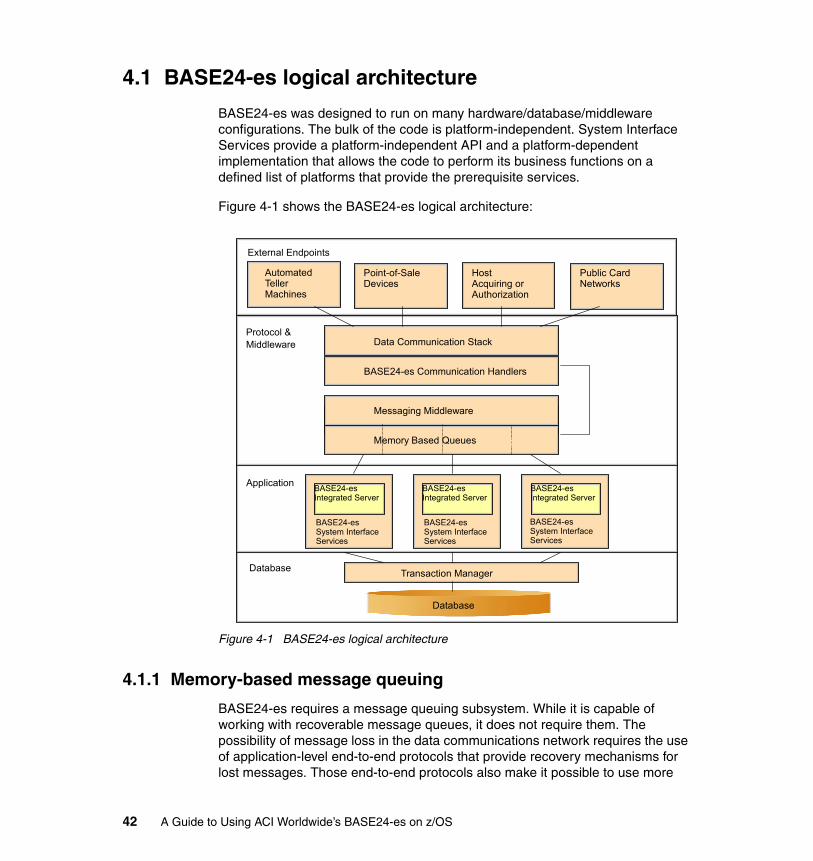
4.1 BASE24-es logical architecture
BASE24-es was designed to run on many hardware/database/middleware configurations. The bulk of the code is platform-independent. System Interface Services provide a platform-independent API and a platform-dependent implementation that allows the code to perform its business functions on a defined list of platforms that provide the prerequisite services.
Figure 4-1 shows the BASE24-es logical architecture:
Figure 4-1 BASE24-es logical architecture
4.1.1 Memory-based message queuing
BASE24-es requires a message queuing subsystem. While it is capable of working with recoverable message queues, it does not require them. The possibility of message loss in the data communications network requires the use of application-level end-to-end protocols that provide recovery mechanisms for lost messages. Those end-to-end protocols also make it possible to use more
External Endpoints
Data Communication StackProtocol &Middleware
Application
Database Transaction Manager
Database
BASE24-es Communication Handlers
Messaging Middleware
Memory Based Queues
Automated Teller Machines
Point-of-Sale Devices
Host Acquiring or Authorization
Public Card Networks
BASE24-es Integrated Server
BASE24-es System Interface Services
BASE24-es Integrated Server
BASE24-es System Interface Services
BASE24-es Integrated Server
BASE24-es System Interface Services
42 A Guide to Using ACI Worldwide’s BASE24-es on z/OS

efficient memory-based message queuing internally within BASE24-es; in the unlikely event that messages on a memory-based queue are lost, end-to-end protocols assure financial integrity.
IBM System z platforms offer at least two subsystems that provide high performance memory-based message queuing that meets the requirements of BASE24-es.
� WebSphere MQ is an industry-leading stand-alone message queuing product that meets the requirements of BASE24-es.
� CICS Transient Data Queues meet the requirements of BASE24-es.
4.1.2 Indexed structured file system or relational database
BASE24-es requires indexed access to structured data, along with record locking and the other features commonly associated with a structured access method.
VSAM with Record Level Sharing (RLS) meets the requirements of BASE24-es for an efficient, scalable and reliable file system providing shared record-level access to multiple concurrent instances of the BASE24-es Integrated Server. In addition to enhanced performance, scalability, and reliability, the CICS API to VSAM/RLS allows access to additional functionality relative to traditional CICS/FOR file sharing.
DB2 support is planned for a future release. Contact ACI for details.
4.1.3 Transaction manager
BASE24-es requires a transaction manager that can provide transactional integrity and rollback capability.
On IBM System z, CICS provides an industry-leading transaction manager.
4.1.4 Data communications
At a minimum, BASE24-es requires a sockets-based TCP/IP communications stack.
IBM System z provides a fully functional sockets implementation; furthermore, the Virtual Telecommunications Access Method (VTAM) also provides robust access to other communications methods such as 3270 Bisync and SNA to CICS-based applications.
Chapter 4. BASE24-es technical architecture on z/OS 43
4.1.5 Other requirements
In addition to the functional requirements defined here, BASE24-es has inherent non-functional requirements for an environment that meets requisite standards of scalability, manageability, and reliability. IBM System z hardware with the z/OS Operating System, sysplex, and CICSplex System Manager, provides a level of manageability, reliability, and scalability that is sufficient to meet BASE24-es stringent standards for providing a highly available Online Transaction Processing (OLTP) system. For further information, refer to 3.1, “How z/OS addresses non-functional requirements” on page 24.
4.2 BASE24-es physical architecture on System z
Because of its industry-leading position as an OLTP processing environment, and the access to other required services that it can provide, CICS was selected as the primary runtime-environment for BASE24-es on z/OS.
CICS sockets provide efficient TCP/IP communications, while the CICS VTAM API provides access to existing communications protocols. CICS file access in conjunction with SMSVSAM provides efficient and scalable record-level shared file access, while CICS itself is a world-class transaction manager. Although WebSphere MQ is a supported alternative, CICS itself provides entirely adequate message queuing and delivery capabilities. CICS Multiple Region Operations (MRO) and sysplex provide scalability and help provide availability.
4.2.1 Long-running tasks
Many BASE24-es CICS components, including many of the most heavily-used components, are implemented as long-running CICS tasks.
Most of the external endpoints with which BASE24-es communicates via TCP/IP use long-lived sockets, and require a long-running task to maintain the socket. In addition, the BASE24-es architecture is based on large C++ executables with substantial initialization cost. It is far more efficient to process many units of work in a single task instance. Accordingly, BASE24-es makes use of long-lived IP handler and Integrated Server tasks.
The Integrated Server is a single executable program that consists of C++ components responsible for the various elements of transaction processing, including interfaces to acquiring endpoints, issuing endpoints, cryptographic facilities, routing and authorization. The integrated facilities minimize the overhead of invoking many separate small CICS programs.
44 A Guide to Using ACI Worldwide’s BASE24-es on z/OS

As of BASE24-es Version 06.2, interfaces to all supported acquiring endpoints except ATMs are linked into the Integrated Server program. And as of BASE24-es Version 06.4, ATM interfaces will be included as well.
Multiple instances of the long-lived Integrated Server task run in a single CICS region to achieve the parallelism normally achieved with many short-lived CICS tasks running in a single region.
4.2.2 Non-recoverable TDQs
As noted in 4.1.1, “Memory-based message queuing” on page 42,the end-to-end application-level protocols used by all remote endpoints make it generally unnecessary for BASE24-es to make use of persistent queuing, enabling it to take advantage of the far better performance characteristic of memory-based queuing. In general the use of recoverable TDQs in the CICS implementation of BASE24-es results in unacceptable performance degradation, and all TDQs are assumed to be non-recoverable unless otherwise noted.
4.2.3 Context-free servers
BASE24-es Integrated Servers (IS) are inherently context-free, and thus have zero CICS affinities. Any message directed to a server class can be processed by any instance of that server class in any CICS region or any logical partition (LPAR) as long as all instances of the server class have access to a common file system or database.
BASE24-es TCP/IP communications handlers hold context in the form of the socket established with the remote endpoint. The BASE24-es Message Delivery subsystem (part of System Interface Services) ensures that messages are delivered to the correct instance of the communications handler, in whatever region or LPAR it is located.
4.2.4 Message routing
BASE24-es applications in most cases will send messages asynchronously; that is, they send a message and then proceed with other work and process the response to that message if and when it is received, rather than specifically waiting for a response.
In some cases, BASE24-es applications may send certain messages synchronously; for example, when a request is sent to a low-latency and generally reliable server, the applications may eliminate the overhead of asynchronous processing and wait for a response before proceeding.
Chapter 4. BASE24-es technical architecture on z/OS 45

BASE24-es routing is configured by symbolic name. System Interface Services configuration files map the symbolic name exposed to the platform-independent application code to platform-dependent constructs such as TDQs, CICS transactions, CICS programs, and ACI proprietary constructs built on CICS primitives for enhanced synchronous and asynchronous message delivery.
4.2.5 Single-region deployment
At its very simplest, BASE24-es can theoretically be deployed in a single CICS region. Files and VTAM terminals (if any) are all defined in the same region. A single-region deployment is undesirable for reasons of scalability, availability, performance, and system maintenance. Figure 4-2 illustrates the flow.
Figure 4-2 BASE24-es one-tier deployment
A communications handler (IP or VTAM) receives a message from an external endpoint and places the message on an Integrated Server TDQ read by multiple instances of the IS server class. One instance of the IS server class reads the message from the TDQ and processes it. Based on configuration data and context contained in the message, the IS task routes the response to the component that originated the request.
If the originator was an IP handler, the message is placed on a dedicated TDQ. If the originator was a VTAM terminal-based transaction, a VTAM terminal-based transaction is started on the originating terminal.
BASE24-es IPHandler IPTDQ
BASE24-es VTAMReader/Writer
BASE24-es IntegratedServer
BASE24-es IntegratedServer
IPTDQ
CICS Region
46 A Guide to Using ACI Worldwide’s BASE24-es on z/OS
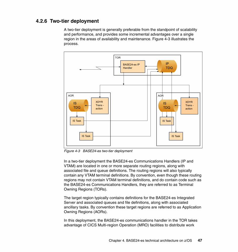
4.2.6 Two-tier deployment
A two-tier deployment is generally preferable from the standpoint of scalability and performance, and provides some incremental advantages over a single region in the areas of availability and maintenance. Figure 4-3 illustrates the process.
Figure 4-3 BASE24-es two-tier deployment
In a two-tier deployment the BASE24-es Communications Handlers (IP and VTAM) are located in one or more separate routing regions, along with associated file and queue definitions. The routing regions will also typically contain any VTAM terminal definitions. By convention, even though these routing regions may not contain VTAM terminal definitions, and do contain code such as the BASE24-es Communications Handlers, they are referred to as Terminal Owning Regions (TORs).
The target region typically contains definitions for the BASE24-es Integrated Server and associated queues and file definitions, along with associated ancillary tasks. By convention these target regions are referred to as Application Owning Regions (AORs).
In this deployment, the BASE24-es communications handler in the TOR takes advantage of CICS Multi-region Operation (MRO) facilities to distribute work
TOR
BASE24-es IPHandler
IPTDQ
AOR
ISTDQ
XDYRTrans -action
IS Task
IS Task
ISTDQ
XDYRTrans -action
IS Task
IS Task
AOR
Chapter 4. BASE24-es technical architecture on z/OS 47
across multiple AORs. Since TDQ writes are not dynamically routed, BASE24-es uses a dynamic routing transaction XDYR. The communications handler starts XDYR, and the start is dynamically routed to an available AOR. Once running in a AOR, XDYR writes to a TDQ in that AOR, where the message is subsequently read and processed by an available member of the Integrated Server class.
4.2.7 Three-tier deployment
Note that a traditional CICS three-tier deployment, where the lowest tier is a CICS File-Owning Region (FOR), is not an option for BASE24-es. The role of the traditional FOR is better served by the facilities of VSAM Record Level Sharing. BASE24-es relies on certain API features available only for RLS files, and will not function in an FOR environment.
4.2.8 Workload management
Asynchronous messaging from the TOR to the AOR combines BASE24-es long-lived Integrated Server tasks to make both CICSPlex® Workload Management (WLM) goal-mode and CICSplex WLM queue mode inappropriate for routing BASE24-es transactions.
BASE24-es provides both a Dynamic Transaction Routing Program for use in a CICSplex environment and a routing user exit for use in a non-CICSplex MRO environment, both of which serve to evenly distribute work across the available BASE24-es AORs.
When an AOR initializes, BASE24-es runs a handshake transaction in the AOR, which starts the BASE24-es Integrated Servers in the AOR and then notifies all configured TORs that the AOR is available to accept workload. The handshake command should also be run when shutting down the region to notify the TORs that the AOR will no longer be available to accept new work.
Figure 4-4 on page 49 shows BASE24-es WLM in a CICSplex environment.
48 A Guide to Using ACI Worldwide’s BASE24-es on z/OS
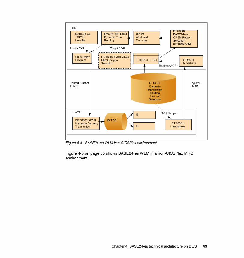
Figure 4-4 BASE24-es WLM in a CICSPlex environment
Figure 4-5 on page 50 shows BASE24-es WLM in a non-CICSPlex MRO environment.
TOR
DRT6002 BASE24-es MRO Region Selection
CICS Relay Program
AOR
DTRCTLDynamic
Transaction Routing Control
Database
Register AOR
DTRCTL TSQ DTR6001 Handshake
Routed Start of XDYR
BASE24-es TCP/IP Handler
EYU9XLOP CICS Dynamic Tran Routing
CPSM Workload Manager
DTR6002 BASE24-es CPSM Region Selection (EYU9WRAM)
Start XDYR Target AOR
Register AOR
DRT6005 XDYR Message Delivery Transaction
IS TDQ
IS
IS
TOR Scope
DTR6001 Handshake
Chapter 4. BASE24-es technical architecture on z/OS 49

Figure 4-5 BASE24-es workload management - non-CPSM
4.2.9 TOR architecture
A BASE24-es TOR is a Terminal Owning Region by convention only, as noted in 4.2.6, “Two-tier deployment” on page 47. It will commonly not contain any VTAM terminal definitions, and will always contain user code. It will also contain file definitions for the BASE24-es DDMF and SDMF routing files, and normally contain file definitions for the TCPIPCFG and SOCKRECS TCP/IP Communications Handler configuration files.
All communications handlers that are in the TOR route messages to the AOR using symbolic routing (see 4.2.4, “Message routing” on page 45), and can route messages using most of the available routing methods. Typically routing will result in a distributed start of the XDYR BASE24-es Message Delivery program as previously described (see 4.2.8, “Workload management” on page 48).
The BASE24-es communications handler code running in the TORs typically consumes relatively little CPU resource.
TOR
DRT6002 BASE24-es MRO Region Selection
CICS Relay Program
AOR
DTRCTLDynamic
Transaction Routing Control
Database
Register AOR
DTRCTL TSQ DTR6001 Handshake
Routed Start of XDYR
BASE24-es TCP/IP Handler
EYU9XLOP CICS Dynamic Tran Routing
CPSM Workload Manager
DTR6002 BASE24-es CPSM Region Selection (EYU9WRAM)
Start XDYR Target AOR
Register AOR
DRT6005 XDYR Message Delivery Transaction
IS TDQ
IS
IS
TOR Scope
DTR6001 Handshake
50 A Guide to Using ACI Worldwide’s BASE24-es on z/OS
TCP/IP client considerationsWhen discussing TCP/IP communications, it is necessary to make a distinction between the TCP/IP client and the application-level client. For example, most public card networks prefer that the member institution act as the TCP/IP client, even though the institution may be solely a card issuer processing requests sent from the network.
The BASE24-es TCP/IP client for CICS can be configured to establish connections with multiple remote IP addresses and ports. It can also be configured to bind to a specified local port. It associates each remote endpoint with a specific BASE24-es symbolic name (see 4.2.4, “Message routing” on page 45) for purposes of internal routing.
Each remote endpoint is associated with a specified symbolic name, which is in turn mapped to a specific CICS destination type and identifier by System Interface Services (SIS) configuration files. All messages from a remote endpoint are delivered to the specified local destination.
See 4.2.6, “Two-tier deployment” on page 47 for an illustration of communications between the TCP/IP client and the BASE24-es authorization components.
Figure 4-6 on page 52 illustrates the components of the TOR associated with the TCP/IP client.
Chapter 4. BASE24-es technical architecture on z/OS 51

Figure 4-6 BASE24-es TOR – IP client
The components illustrated are as follows:
� SOCKRECS has one record for each configured remote endpoint.
� TCPIPCFG has information about the IP Client handler process itself, specifying information such as the symbolic name of the IP handler, and whether it is client or server.
� DDMF has routing information for each symbolic destination in the system.
� SDMF has configuration information for each BASE24-es task that makes use of SIS Message Delivery services.
� The BASE24-es Task Monitor runs at intervals to monitor the health if the IP Client and restart it as required.
TCP/IP server considerationsFor some specific purposes (see 4.2.13, “User interface region architecture” on page 90), BASE24-es makes use of the IBM-provided CSKL listener. However, for OLTP it provides its own listener, the BASE24-es TCP/IP server. Unlike the IBM listener, the BASE24-es server retains ownership of the sockets on which it accepts connections. It is architecturally similar to the BASE24-es TCP/IP client in that respect.
TOR
SOCKRECS
Start XDYR
BASE24-es IP Client
BASE24-es Task Monitor
TCPIPCFG
SDMF
DDMF
52 A Guide to Using ACI Worldwide’s BASE24-es on z/OS
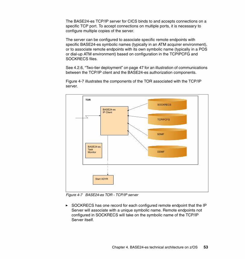
The BASE24-es TCP/IP server for CICS binds to and accepts connections on a specific TCP port. To accept connections on multiple ports, it is necessary to configure multiple copies of the server.
The server can be configured to associate specific remote endpoints with specific BASE24-es symbolic names (typically in an ATM acquirer environment), or to associate remote endpoints with its own symbolic name (typically in a POS or dial-up ATM environment) based on configuration in the TCPIPCFG and SOCKRECS files.
See 4.2.6, “Two-tier deployment” on page 47 for an illustration of communications between the TCP/IP client and the BASE24-es authorization components.
Figure 4-7 illustrates the components of the TOR associated with the TCP/IP server.
Figure 4-7 BASE24-es TOR - TCP/IP server
� SOCKRECS has one record for each configured remote endpoint that the IP Server will associate with a unique symbolic name. Remote endpoints not configured in SOCKRECS will take on the symbolic name of the TCP/IP Server itself.
TOR
SOCKRECS
Start XDYR
BASE24-es IP Client
BASE24-es Task Monitor
TCPIPCFG
SDMF
DDMF
Chapter 4. BASE24-es technical architecture on z/OS 53

� TCPIPCFG has information about the IP Server process itself, specifying information such as the symbolic name of the IP handler, and whether it is client or server.
� DDMF has routing information for each symbolic destination in the system.
� SDMF has configuration information for each BASE24-es task that makes use of SIS Message Delivery services.
� The BASE24-es Task Monitor runs at intervals to monitor the health of the IP Server and restart it as required.
VTAM considerationsBASE24-es makes use of CICS/VTAM facilities to support non-IP based protocols on z/OS. VTAM reader/writer programs are developed as the need arises. Current offerings include SNA LU.0 and SNA LU.2.
Figure 4-8 illustrates a BASE24-es TOR – VTAM Reader/Writer configuration.
Figure 4-8 BASE24-es TOR – VTAM Reader/Writer
1. An incoming message causes the VTAM reader/writer transaction to be started on the originating terminal. The reader/writer calls RECEIVE to get the message.
2. The reader/writer adds a BASE24-es internal header to the message, specifying among other things the symbolic source associated with its terminal. It starts the AOR Message Delivery transaction XDYR, and terminates. The start is routed to an available AOR.
TOR
VTAM Terminal
VTAM Reader/Writer
XDYR
AOR
IS TDQ
Integrated Server
1
22
34
5
6
54 A Guide to Using ACI Worldwide’s BASE24-es on z/OS
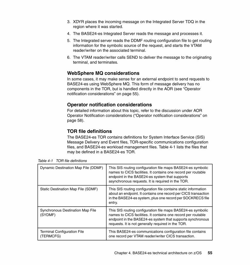
3. XDYR places the incoming message on the Integrated Server TDQ in the region where it was started.
4. The BASE24-es Integrated Server reads the message and processes it.
5. The Integrated server reads the DDMF routing configuration file to get routing information for the symbolic source of the request, and starts the VTAM reader/writer on the associated terminal.
6. The VTAM reader/writer calls SEND to deliver the message to the originating terminal, and terminates.
WebSphere MQ considerationsIn some cases, it may make sense for an external endpoint to send requests to BASE24-es using WebSphere MQ. This form of message delivery has no components in the TOR, but is handled directly in the AOR (see “Operator notification considerations” on page 55).
Operator notification considerationsFor detailed information about this topic, refer to the discussion under AOR Operator Notification considerations (“Operator notification considerations” on page 58).
TOR file definitionsThe BASE24-es TOR contains definitions for System Interface Service (SIS) Message Delivery and Event files, TOR-specific communications configuration files, and BASE24-es workload management files. Table 4-1 lists the files that may be defined in a BASE24-es TOR.
Table 4-1 TOR file definitions
Dynamic Destination Map File (DDMF) This SIS routing configuration file maps BASE24-es symbolic names to CICS facilities. It contains one record per routable endpoint in the BASE24-es system that supports asynchronous requests. It is required in the TOR.
Static Destination Map File (SDMF) This SIS routing configuration file contains static information about an endpoint. It contains one record per CICS transaction in the BASE24-es system, plus one record per SOCKRECS file entry.
Synchronous Destination Map File (SYDMF)
This SIS routing configuration file maps BASE24-es symbolic names to CICS facilities. It contains one record per routable endpoint in the BASE24-es system that supports synchronous requests. It is not generally required in the TOR.
Terminal Configuration File (TERMCFG)
This BASE24-es communications configuration file contains one record per VTAM reader/writer CICS transaction.
Chapter 4. BASE24-es technical architecture on z/OS 55
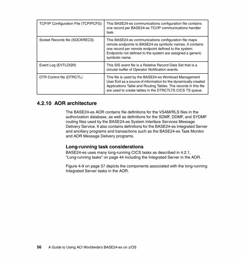
4.2.10 AOR architecture
The BASE24-es AOR contains file definitions for the VSAM/RLS files in the authorization database, as well as definitions for the SDMF, DDMF, and SYDMF routing files used by the BASE24-es System Interface Services Message Delivery Service. It also contains definitions for the BASE24-es Integrated Server and ancillary programs and transactions such as the BASE24-es Task Monitor and AOR Message Delivery programs.
Long-running task considerationsBASE24-es uses many long-running CICS tasks as described in 4.2.1, “Long-running tasks” on page 44 including the Integrated Server in the AOR.
Figure 4-9 on page 57 depicts the components associated with the long-running Integrated Server tasks in the AOR.
TCP/IP Configuration File (TCPIPCFG) This BASE24-es communications configuration file contains one record per BASE24-es TCI/IP communications handler task.
Socket Records file (SOCKRECS) This BASE24-es communications configuration file maps remote endpoints to BASE24-es symbolic names. It contains one record per remote endpoint defined to the system. Endpoints not defined to the system are assigned a generic symbolic name.
Event Log (EVTLOGR) This SIS event file is a Relative Record Data Set that is a circular buffer of Operator Notification events.
DTR Control file (DTRCTL) This file is used by the BASE24-es Workload Management User Exit as a source of information for the dynamically created Applications Table and Routing Tables. The records in this file are used to create tables in the DTRCTLTS CICS TS queue.
56 A Guide to Using ACI Worldwide’s BASE24-es on z/OS

Figure 4-9 BASE24-es AOR - Long-running tasks
The BASE24-es Integrated Server tasks are started by the BASE24-es Task Monitor program during CICS region initialization. They in turn create a configurable number of instances of one or more BASE24-es Integrated Server classes. (It may be desirable to create more than one Integrated Server class to handle specific workloads. A separate TDQ is configured for each server class.)
When the Integrated Servers initialize, they enter themselves in a shared memory table associated with the server class in the AOR. The Task Monitor is then scheduled to rerun at configurable intervals to monitor the state of the servers it has started, and restart them as required.
When the Integrated Server long-running tasks find no messages on their TDQ, they post a timer and wait. When the AOR Message Deliver Program runs, it writes the message to the TDQ associated with the correct server class. It then examines the shared memory table and checks the state of class member tasks. If it finds a task that is waiting on a timer, it cancels the timer so the task can wake and process a message from the TDQ.
It is possible that another task has already processed the delivered message. If so, the newly-awakened task simply re-posts its timer and waits; the associated cost is low.
AO1R
XDYR(BASE24-es AOR Message Delivery Program)
AOR1 ISnn MDS Memory Table
ISnn TDQ
ISnn (BASE24-es Integrated Server)
BASE24-es Task Monitor
Timer
Timer
ISnn (BASE24-es Integrated Server)
Chapter 4. BASE24-es technical architecture on z/OS 57

Since the shared memory table is specifically designed to be associated with the tasks running in a single AOR, it does not introduce any undesirable CICS affinities.
Each group of long-running tasks associated with a single queue is commonly referred to as a BASE24-es server class.
Operator notification considerations From time to time, BASE24-es may encounter conditions that it wishes to bring to the attention of a human or programmatic operator.
Figure 4-10 illustrates how those operator notifications are generated.
Figure 4-10 BASE24-es Operator Notifications
When an operator notification is generated, the generating task writes it to the Event Log TDQ. The Event Log TDQ then triggers the BASE24-es Event Distributor transaction.
BASE24-es region
BASE24-es Application BASE24-es
EVTLOGR TDQ
EINF
BASE24-es R300 Event Perusal Transaction
CICS Spooler (CEEOUT)BASE24-es Event
Distributor Transaction
EEER
EWRN
ECRT
CICS OperatorBASE24-es EVTLOGR (VSAM RLS
Shared Relative Record Data Set)
58 A Guide to Using ACI Worldwide’s BASE24-es on z/OS
The Event Distributor transaction first writes the event to a circular Relative Record data set, which is intended to give a system-wide picture of associated events. You can peruse this file with the BASE24-es R300 Event Log Perusal transaction.
Then, based on the severity of the notification, the Event Distributor starts one of four Alternate Distributor transactions: EINF (Informational Notification), EWRN (Warning Notification), EERR (Error Notification) or ECRT (Critical Notification).
By default, these four transactions are associated with the same program, SIADIST, which simply writes to the local CICS spooler. However, the real flexibility of the notification architecture lies in the fact that the program associated with these transactions is intended to be user-replaceable. The user might, for example, associate EERR and ECRT with a program that also writes to the z/OS console.
Tivoli Monitoring considerationsCurrently there is no API available to CICS applications to let them raise events to the Tivoli Enterprise™ Console. CPSM has an API into Tivoli, and CPSM can be used to send messages or alerts to NetView®, and if NetView is set up, it can route to the Tivoli Event Console. Though it is not part of BASE24-es standard product, an Alternate Distributor (described in “Operator notification considerations” on page 55) could be developed to make use of these facilities.
WebSphere MQ considerationsA BASE24-es Integrated Server class or other BASE24-es Message Delivery Service-based task can be configured to read a WebSphere MQ queue rather than a CICS TDQ.
Figure 4-11 on page 60 shows an Integrated Server class configured to read messages with no BASE24-es internal header, rather than the more typical configuration in which the Integrated Server expects messages with a BASE24-es internal header from a CICS TDQ. In this configuration, the BASE24-es System Interface Services Message Delivery Service assigns a symbolic name to the remote endpoint, much as a BASE24-es Communications Handler in the TOR normally would, and creates an internal BASE24-es header.
The Integrated Server processes the request and routes the response to the originating endpoint by sending the response to symbolic name assigned by the Message Delivery Service.
The Message Delivery Service determines that symbolic name is associated with a WebSphere MQ, and that messages to that destination should be placed on the queue without a BASE24-es internal header.
Chapter 4. BASE24-es technical architecture on z/OS 59
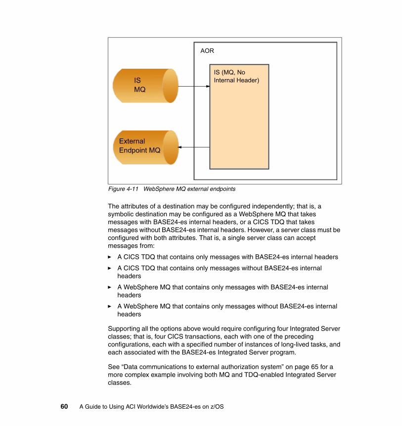
Figure 4-11 WebSphere MQ external endpoints
The attributes of a destination may be configured independently; that is, a symbolic destination may be configured as a WebSphere MQ that takes messages with BASE24-es internal headers, or a CICS TDQ that takes messages without BASE24-es internal headers. However, a server class must be configured with both attributes. That is, a single server class can accept messages from:
� A CICS TDQ that contains only messages with BASE24-es internal headers
� A CICS TDQ that contains only messages without BASE24-es internal headers
� A WebSphere MQ that contains only messages with BASE24-es internal headers
� A WebSphere MQ that contains only messages without BASE24-es internal headers
Supporting all the options above would require configuring four Integrated Server classes; that is, four CICS transactions, each with one of the preceding configurations, each with a specified number of instances of long-lived tasks, and each associated with the BASE24-es Integrated Server program.
See “Data communications to external authorization system” on page 65 for a more complex example involving both MQ and TDQ-enabled Integrated Server classes.
IS (MQ, NoInternal Header)
AOR
ExternalEndpoint MQ
ISMQ
60 A Guide to Using ACI Worldwide’s BASE24-es on z/OS
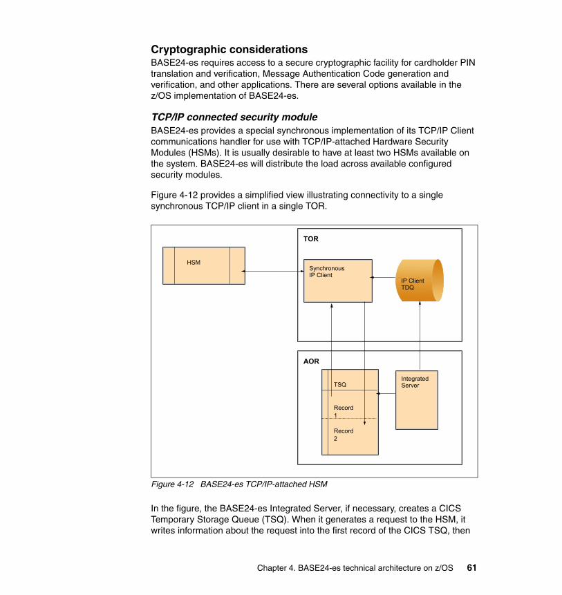
Cryptographic considerationsBASE24-es requires access to a secure cryptographic facility for cardholder PIN translation and verification, Message Authentication Code generation and verification, and other applications. There are several options available in the z/OS implementation of BASE24-es.
TCP/IP connected security moduleBASE24-es provides a special synchronous implementation of its TCP/IP Client communications handler for use with TCP/IP-attached Hardware Security Modules (HSMs). It is usually desirable to have at least two HSMs available on the system. BASE24-es will distribute the load across available configured security modules.
Figure 4-12 provides a simplified view illustrating connectivity to a single synchronous TCP/IP client in a single TOR.
Figure 4-12 BASE24-es TCP/IP-attached HSM
In the figure, the BASE24-es Integrated Server, if necessary, creates a CICS Temporary Storage Queue (TSQ). When it generates a request to the HSM, it writes information about the request into the first record of the CICS TSQ, then
TOR
TSQ
Record1
Record2
HSM
Integrated Server
Synchronous IP Client
AOR
IP Client TDQ
Chapter 4. BASE24-es technical architecture on z/OS 61

places the request on the CICS TDQ associated with the Synchronous IP Client, and sets a timer.
The Synchronous IP Client reads its TDQ and sends the request to the HSM over a long-lived socket connection. It then reads the response from the socket, validates that the response is still related to the request specified in the first record of the TSQ, places the response in the second record of the TSQ, and cancels the timer set by the Integrated Server.
The Integrated Server wakes up and, finding a response in the second record of the TSQ, processes the response from the TCP/IP-attached HSM.
VTAM attached security moduleBASE24-es also supports synchronous communication with VTAM-attached security modules; see Figure 4-13.
Figure 4-13 BASE24-es VTAM-attached HSM
As shown in the figure, the BASE24-es Integrated Server, if necessary, creates a CICS Temporary Storage Queue (TSQ). When it generates a request to the HSM, it writes information about the request into the first record of the CICS
TOR
TSQ
Record1
Record2
HSM
Integrated Server
VTAM Writer/Reader
AOR
62 A Guide to Using ACI Worldwide’s BASE24-es on z/OS
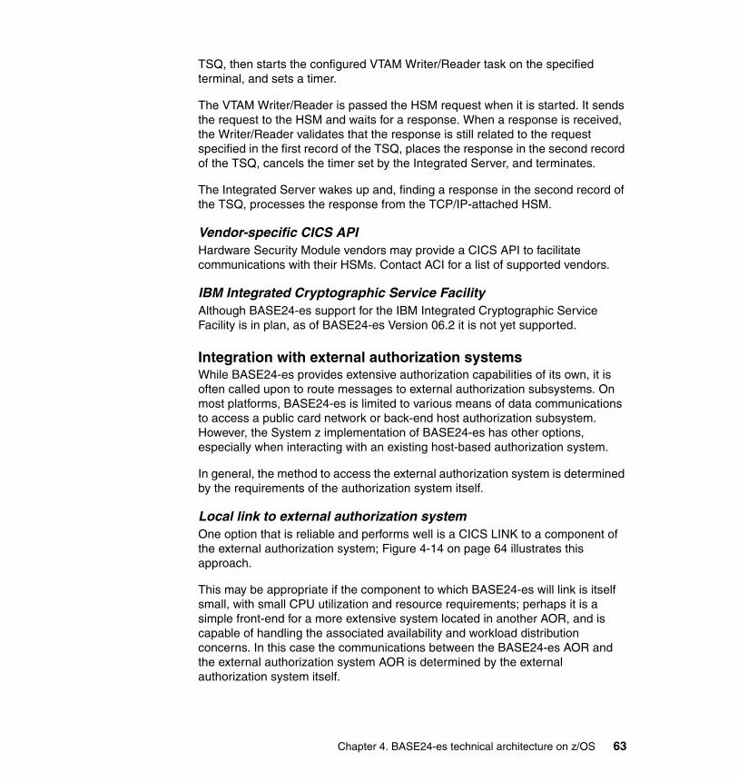
TSQ, then starts the configured VTAM Writer/Reader task on the specified terminal, and sets a timer.
The VTAM Writer/Reader is passed the HSM request when it is started. It sends the request to the HSM and waits for a response. When a response is received, the Writer/Reader validates that the response is still related to the request specified in the first record of the TSQ, places the response in the second record of the TSQ, cancels the timer set by the Integrated Server, and terminates.
The Integrated Server wakes up and, finding a response in the second record of the TSQ, processes the response from the TCP/IP-attached HSM.
Vendor-specific CICS APIHardware Security Module vendors may provide a CICS API to facilitate communications with their HSMs. Contact ACI for a list of supported vendors.
IBM Integrated Cryptographic Service FacilityAlthough BASE24-es support for the IBM Integrated Cryptographic Service Facility is in plan, as of BASE24-es Version 06.2 it is not yet supported.
Integration with external authorization systemsWhile BASE24-es provides extensive authorization capabilities of its own, it is often called upon to route messages to external authorization subsystems. On most platforms, BASE24-es is limited to various means of data communications to access a public card network or back-end host authorization subsystem. However, the System z implementation of BASE24-es has other options, especially when interacting with an existing host-based authorization system.
In general, the method to access the external authorization system is determined by the requirements of the authorization system itself.
Local link to external authorization systemOne option that is reliable and performs well is a CICS LINK to a component of the external authorization system; Figure 4-14 on page 64 illustrates this approach.
This may be appropriate if the component to which BASE24-es will link is itself small, with small CPU utilization and resource requirements; perhaps it is a simple front-end for a more extensive system located in another AOR, and is capable of handling the associated availability and workload distribution concerns. In this case the communications between the BASE24-es AOR and the external authorization system AOR is determined by the external authorization system itself.
Chapter 4. BASE24-es technical architecture on z/OS 63
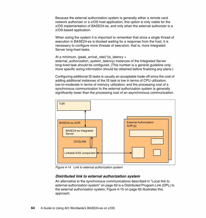
Because the external authorization system is generally either a remote card network authorizer or a z/OS host application, this option is only viable for the z/OS implementation of BASE24-es, and only when the external authorizer is a z/OS-based application.
When sizing the system it is important to remember that since a single thread of execution in BASE24-es is blocked waiting for a response from the host, it is necessary to configure more threads of execution, that is, more Integrated Server long-lived tasks.
At a minimum, (peak_arrival_rate)*(is_latency + external_authorization_system_latency) instances of the Integrated Server long-lived task should be configured. (This number is a general guideline only; more specific sizing information should be obtained before finalizing any plans.)
Configuring additional IS tasks is usually an acceptable trade-off since the cost of adding additional instances of the IS task is low in terms of CPU utilization; low-to-moderate in terms of memory utilization; and the processing cost of a synchronous communication to the external authorization system is generally significantly lower than the processing cost of an asynchronous communication.
Figure 4-14 Link to external authorization system
Distributed link to external authorization systemAn alternative to the synchronous communications described in “Local link to external authorization system” on page 63 is a Distributed Program Link (DPL) to the external authorization system; Figure 4-15 on page 65 illustrates this approach.
TOR
BASE24-es Integrated Server
BASE24-es AOR
CICSLINK
Linkable EAS component
External AuthorizationAOR [s]
64 A Guide to Using ACI Worldwide’s BASE24-es on z/OS
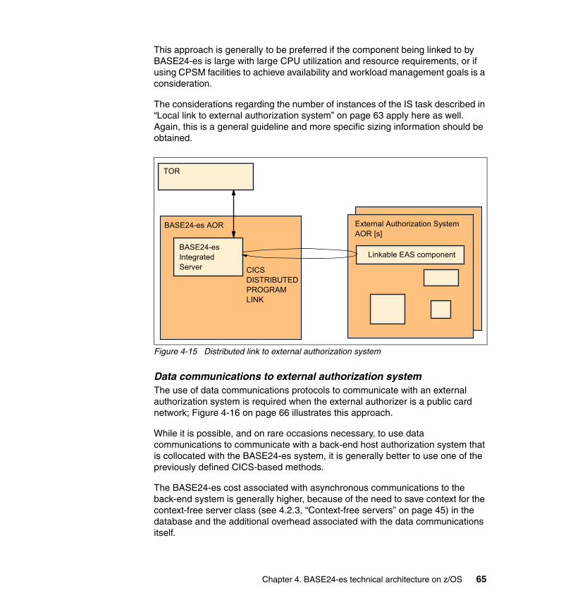
This approach is generally to be preferred if the component being linked to by BASE24-es is large with large CPU utilization and resource requirements, or if using CPSM facilities to achieve availability and workload management goals is a consideration.
The considerations regarding the number of instances of the IS task described in “Local link to external authorization system” on page 63 apply here as well. Again, this is a general guideline and more specific sizing information should be obtained.
Figure 4-15 Distributed link to external authorization system
Data communications to external authorization systemThe use of data communications protocols to communicate with an external authorization system is required when the external authorizer is a public card network; Figure 4-16 on page 66 illustrates this approach.
While it is possible, and on rare occasions necessary, to use data communications to communicate with a back-end host authorization system that is collocated with the BASE24-es system, it is generally better to use one of the previously defined CICS-based methods.
The BASE24-es cost associated with asynchronous communications to the back-end system is generally higher, because of the need to save context for the context-free server class (see 4.2.3, “Context-free servers” on page 45) in the database and the additional overhead associated with the data communications itself.
TOR
BASE24-esIntegratedServer
BASE24-es AOR External Authorization SystemAOR [s]
Linkable EAS component
CICSDISTRIBUTEDPROGRAMLINK
Chapter 4. BASE24-es technical architecture on z/OS 65
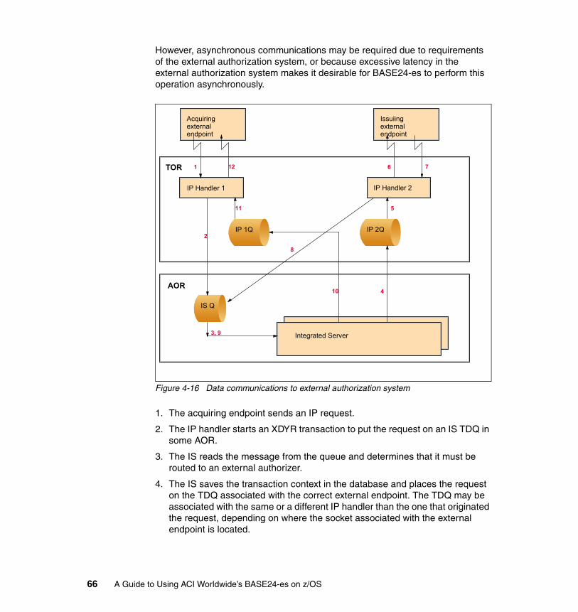
However, asynchronous communications may be required due to requirements of the external authorization system, or because excessive latency in the external authorization system makes it desirable for BASE24-es to perform this operation asynchronously.
Figure 4-16 Data communications to external authorization system
1. The acquiring endpoint sends an IP request.
2. The IP handler starts an XDYR transaction to put the request on an IS TDQ in some AOR.
3. The IS reads the message from the queue and determines that it must be routed to an external authorizer.
4. The IS saves the transaction context in the database and places the request on the TDQ associated with the correct external endpoint. The TDQ may be associated with the same or a different IP handler than the one that originated the request, depending on where the socket associated with the external endpoint is located.
IP Handler 1
IP 1Q
Integrated Server
TOR
Acquiring external endpoint
Issuiing external endpoint
IP Handler 2
IP 2Q
IS Q
AOR
1 12
2
3, 9
4
5
6 7
8
10
11
66 A Guide to Using ACI Worldwide’s BASE24-es on z/OS

5. The IP handler reads the request from the TDQ and locates the socket associated with the external endpoint.
6. The IP handler sends the request to the external authorizer.
7. The external authorizer sends a response.
8. The IP handler starts a XDYR transaction to place the response on the TDQ associated with messages from the external endpoint.
9. The IS reads the response from the TDQ.
10.The IS retrieves the context from the database, updates the database, and routes the response to the TDQ associated with the originating endpoint.
11.The IP handler reads the message from the TDQ and locates the socket associated with the originating external endpoint.
12.The IP handler routes the response to the originating external endpoint.
WebSphere MQ to external authorization systemBASE24-es can be configured to use WebSphere MQ to communicate with WebSphere MQ-enabled External Authorization Systems or acquiring endpoints. Figure 4-17 illustrates one possible configuration with asynchronous messaging to the External Authorization System.
(This example was chosen for illustrative purposes. Asynchronous messaging is generally to be preferred when data communications latency and reliability issues are introduced into the interface between BASE24-es and the External Authorization System; this may or may not be the case with WebSphere MQ.)
Figure 4-17 WebSphere MQ to external authorization system
TOR
IS01TDQ
IS01(TDQ/Internal Header Server Class)
AOR
IS02(MQ/NoHeader Server Class)
EASMQ
IS02MQ
Chapter 4. BASE24-es technical architecture on z/OS 67
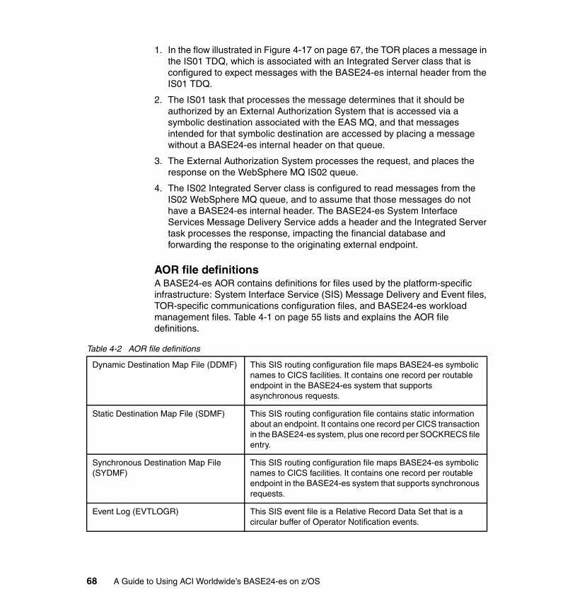
1. In the flow illustrated in Figure 4-17 on page 67, the TOR places a message in the IS01 TDQ, which is associated with an Integrated Server class that is configured to expect messages with the BASE24-es internal header from the IS01 TDQ.
2. The IS01 task that processes the message determines that it should be authorized by an External Authorization System that is accessed via a symbolic destination associated with the EAS MQ, and that messages intended for that symbolic destination are accessed by placing a message without a BASE24-es internal header on that queue.
3. The External Authorization System processes the request, and places the response on the WebSphere MQ IS02 queue.
4. The IS02 Integrated Server class is configured to read messages from the IS02 WebSphere MQ queue, and to assume that those messages do not have a BASE24-es internal header. The BASE24-es System Interface Services Message Delivery Service adds a header and the Integrated Server task processes the response, impacting the financial database and forwarding the response to the originating external endpoint.
AOR file definitionsA BASE24-es AOR contains definitions for files used by the platform-specific infrastructure: System Interface Service (SIS) Message Delivery and Event files, TOR-specific communications configuration files, and BASE24-es workload management files. Table 4-1 on page 55 lists and explains the AOR file definitions.
Table 4-2 AOR file definitions
Dynamic Destination Map File (DDMF) This SIS routing configuration file maps BASE24-es symbolic names to CICS facilities. It contains one record per routable endpoint in the BASE24-es system that supports asynchronous requests.
Static Destination Map File (SDMF) This SIS routing configuration file contains static information about an endpoint. It contains one record per CICS transaction in the BASE24-es system, plus one record per SOCKRECS file entry.
Synchronous Destination Map File (SYDMF)
This SIS routing configuration file maps BASE24-es symbolic names to CICS facilities. It contains one record per routable endpoint in the BASE24-es system that supports synchronous requests.
Event Log (EVTLOGR) This SIS event file is a Relative Record Data Set that is a circular buffer of Operator Notification events.
68 A Guide to Using ACI Worldwide’s BASE24-es on z/OS
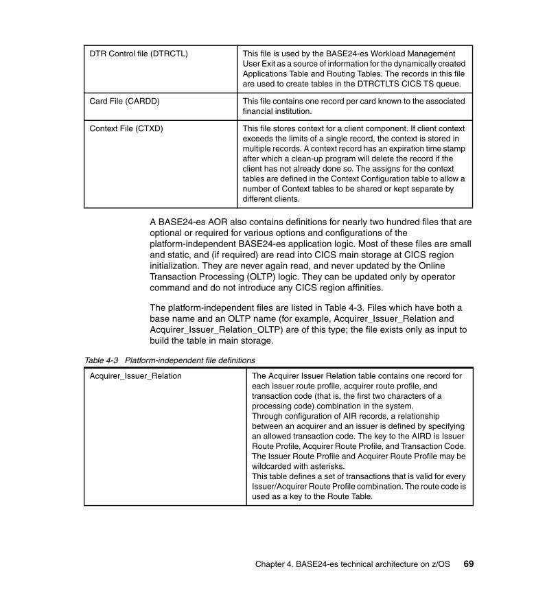
A BASE24-es AOR also contains definitions for nearly two hundred files that are optional or required for various options and configurations of the platform-independent BASE24-es application logic. Most of these files are small and static, and (if required) are read into CICS main storage at CICS region initialization. They are never again read, and never updated by the Online Transaction Processing (OLTP) logic. They can be updated only by operator command and do not introduce any CICS region affinities.
The platform-independent files are listed in Table 4-3. Files which have both a base name and an OLTP name (for example, Acquirer_Issuer_Relation and Acquirer_Issuer_Relation_OLTP) are of this type; the file exists only as input to build the table in main storage.
Table 4-3 Platform-independent file definitions
DTR Control file (DTRCTL) This file is used by the BASE24-es Workload Management User Exit as a source of information for the dynamically created Applications Table and Routing Tables. The records in this file are used to create tables in the DTRCTLTS CICS TS queue.
Card File (CARDD) This file contains one record per card known to the associated financial institution.
Context File (CTXD) This file stores context for a client component. If client context exceeds the limits of a single record, the context is stored in multiple records. A context record has an expiration time stamp after which a clean-up program will delete the record if the client has not already done so. The assigns for the context tables are defined in the Context Configuration table to allow a number of Context tables to be shared or kept separate by different clients.
Acquirer_Issuer_Relation The Acquirer Issuer Relation table contains one record for each issuer route profile, acquirer route profile, and transaction code (that is, the first two characters of a processing code) combination in the system. Through configuration of AIR records, a relationship between an acquirer and an issuer is defined by specifying an allowed transaction code. The key to the AIRD is Issuer Route Profile, Acquirer Route Profile, and Transaction Code. The Issuer Route Profile and Acquirer Route Profile may be wildcarded with asterisks. This table defines a set of transactions that is valid for every Issuer/Acquirer Route Profile combination. The route code is used as a key to the Route Table.
Chapter 4. BASE24-es technical architecture on z/OS 69
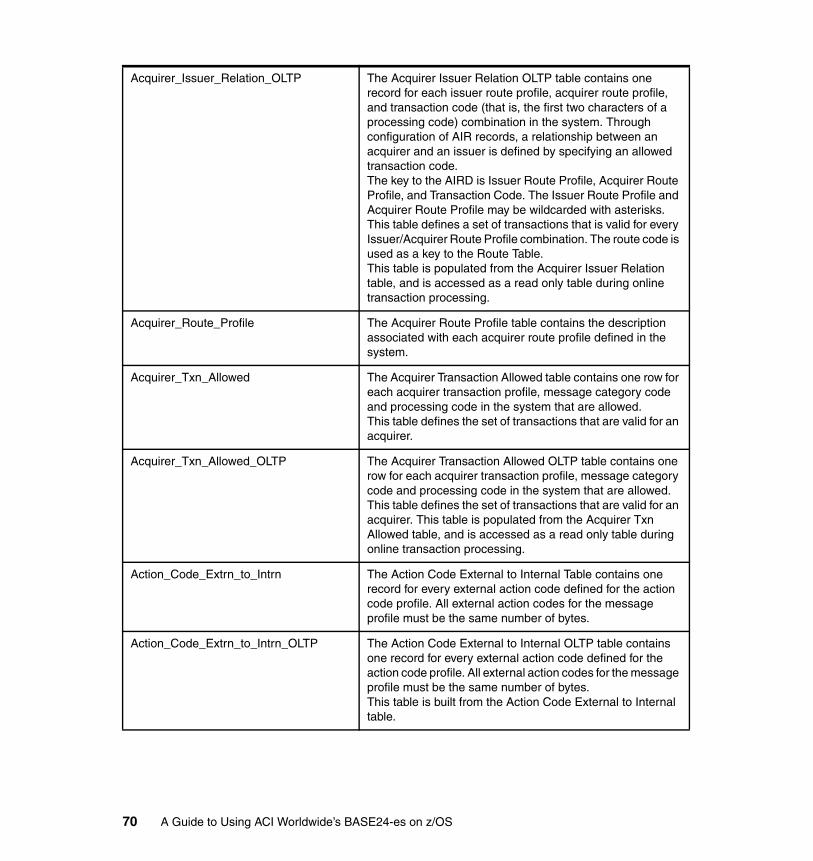
Acquirer_Issuer_Relation_OLTP The Acquirer Issuer Relation OLTP table contains one record for each issuer route profile, acquirer route profile, and transaction code (that is, the first two characters of a processing code) combination in the system. Through configuration of AIR records, a relationship between an acquirer and an issuer is defined by specifying an allowed transaction code. The key to the AIRD is Issuer Route Profile, Acquirer Route Profile, and Transaction Code. The Issuer Route Profile and Acquirer Route Profile may be wildcarded with asterisks. This table defines a set of transactions that is valid for every Issuer/Acquirer Route Profile combination. The route code is used as a key to the Route Table. This table is populated from the Acquirer Issuer Relation table, and is accessed as a read only table during online transaction processing.
Acquirer_Route_Profile The Acquirer Route Profile table contains the description associated with each acquirer route profile defined in the system.
Acquirer_Txn_Allowed The Acquirer Transaction Allowed table contains one row for each acquirer transaction profile, message category code and processing code in the system that are allowed. This table defines the set of transactions that are valid for an acquirer.
Acquirer_Txn_Allowed_OLTP The Acquirer Transaction Allowed OLTP table contains one row for each acquirer transaction profile, message category code and processing code in the system that are allowed. This table defines the set of transactions that are valid for an acquirer. This table is populated from the Acquirer Txn Allowed table, and is accessed as a read only table during online transaction processing.
Action_Code_Extrn_to_Intrn The Action Code External to Internal Table contains one record for every external action code defined for the action code profile. All external action codes for the message profile must be the same number of bytes.
Action_Code_Extrn_to_Intrn_OLTP The Action Code External to Internal OLTP table contains one record for every external action code defined for the action code profile. All external action codes for the message profile must be the same number of bytes. This table is built from the Action Code External to Internal table.
70 A Guide to Using ACI Worldwide’s BASE24-es on z/OS

Action_Code_Intrn_to_Extrn The Action Code External to Internal Table contains one record for every external action code defined for the action code profile. All external action codes for the message profile must be the same number of bytes.
Action_Code_Intrn_to_Extrn_OLTP The Action Code External to Internal OLTP Table contains one record for every external action code defined for the action code profile. All external action codes for the message profile must be the same number of bytes. This table is built from the Action Code Internal to External table.
Active_Script_Statistics The Active Script Statistics Table contains one record for each authorizer and message type which is being monitored. The records contain the counts for the script and whether the script is enabled or not. Once the number of transactions processed with the script exceeds the minimum transaction count, the percentage of approvals, denials and referrals are compared to their corresponding threshold limits to determine whether the script should continue to be used or not. If not, the script is disabled. This table is updated during online processing for scripts configured to be monitored. This table should not be audited.
Admin_Card Admin Card Data Source
Audit_Store_and_Forward The Audit Store and Forward (SAF) table contains all the records which are stored to be forwarded to the EAE at a later time.
Audit_Store_and_Forward_Config This table contains SAF Configuration information for Auditing UI functions. It contains SAF limits and time-out values. There should only be one record in this table.
Authorization_Script The Authorization Script Table contains one record for each Authorization Script defined in the Script Configuration data source. It defines whether the script is enabled or not and whether to monitor the script to ensure thresholds are met for the script.
Authorization_Script_OLTP The Authorization Script OLTP Table contains one record for each Authorization Script defined in the Script Configuration data source. It defines whether the script is enabled or not and whether to monitor the script to ensure thresholds are met for the script. This table is populated from the Authorization Script table.
Banknet_Configuration The Banknet Configuration Table contains a record with additional configuration required for each Banknet Interface.
Chapter 4. BASE24-es technical architecture on z/OS 71
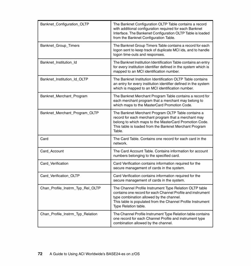
Banknet_Configuration_OLTP The Banknet Configuration OLTP Table contains a record with additional configuration required for each Banknet Interface. The Bankenet Configuration OLTP Table is loaded from the Banknet Configuration Table.
Banknet_Group_Timers The Banknet Group Timers Table contains a record for each logon sent to keep track of duplicate MCI ids, and to handle logon time-outs and responses.
Banknet_Institution_Id The Banknet Institution Identification Table contains an entry for every institution identifier defined in the system which is mapped to an MCI identification number.
Banknet_Institution_Id_OLTP The Banknet Institution Identification OLTP Table contains an entry for every institution identifier defined in the system which is mapped to an MCI identification number.
Banknet_Merchant_Program The Banknet Merchant Program Table contains a record for each merchant program that a merchant may belong to which maps to the MasterCard Promotion Code.
Banknet_Merchant_Program_OLTP The Banknet Merchant Program OLTP Table contains a record for each merchant program that a merchant may belong to which maps to the MasterCard Promotion Code. This table is loaded from the Banknet Merchant Program Table.
Card The Card Table. Contains one record for each card in the network.
Card_Account The Card Account Table. Contains information for account numbers belonging to the specified card.
Card_Verification Card Verification contains information required for the secure management of cards in the system.
Card_Verification_OLTP Card Verification contains information required for the secure management of cards in the system.
Chan_Profile_Instrm_Typ_Rel_OLTP The Channel Profile Instrument Type Relation OLTP table contains one record for each Channel Profile and instrument type combination allowed by the channel. This table is populated from the Channel Profile Instrument Type Relation table.
Chan_Profile_Instrm_Typ_Relation The Channel Profile Instrument Type Relation table contains one record for each Channel Profile and instrument type combination allowed by the channel.
72 A Guide to Using ACI Worldwide’s BASE24-es on z/OS
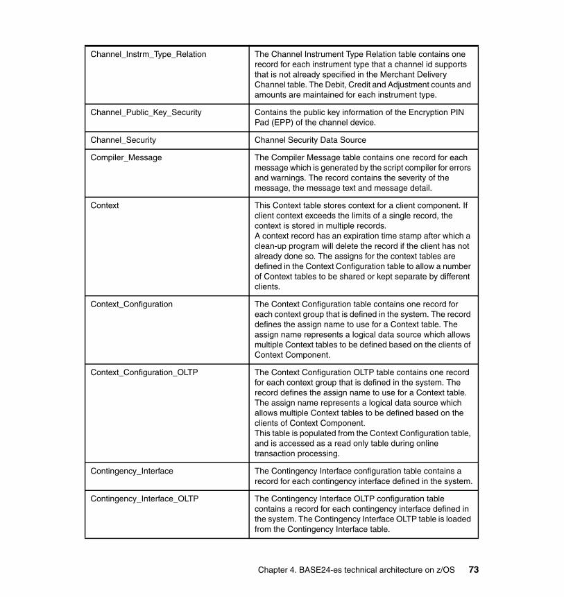
Channel_Instrm_Type_Relation The Channel Instrument Type Relation table contains one record for each instrument type that a channel id supports that is not already specified in the Merchant Delivery Channel table. The Debit, Credit and Adjustment counts and amounts are maintained for each instrument type.
Channel_Public_Key_Security Contains the public key information of the Encryption PIN Pad (EPP) of the channel device.
Channel_Security Channel Security Data Source
Compiler_Message The Compiler Message table contains one record for each message which is generated by the script compiler for errors and warnings. The record contains the severity of the message, the message text and message detail.
Context This Context table stores context for a client component. If client context exceeds the limits of a single record, the context is stored in multiple records. A context record has an expiration time stamp after which a clean-up program will delete the record if the client has not already done so. The assigns for the context tables are defined in the Context Configuration table to allow a number of Context tables to be shared or kept separate by different clients.
Context_Configuration The Context Configuration table contains one record for each context group that is defined in the system. The record defines the assign name to use for a Context table. The assign name represents a logical data source which allows multiple Context tables to be defined based on the clients of Context Component.
Context_Configuration_OLTP The Context Configuration OLTP table contains one record for each context group that is defined in the system. The record defines the assign name to use for a Context table. The assign name represents a logical data source which allows multiple Context tables to be defined based on the clients of Context Component. This table is populated from the Context Configuration table, and is accessed as a read only table during online transaction processing.
Contingency_Interface The Contingency Interface configuration table contains a record for each contingency interface defined in the system.
Contingency_Interface_OLTP The Contingency Interface OLTP configuration table contains a record for each contingency interface defined in the system. The Contingency Interface OLTP table is loaded from the Contingency Interface table.
Chapter 4. BASE24-es technical architecture on z/OS 73
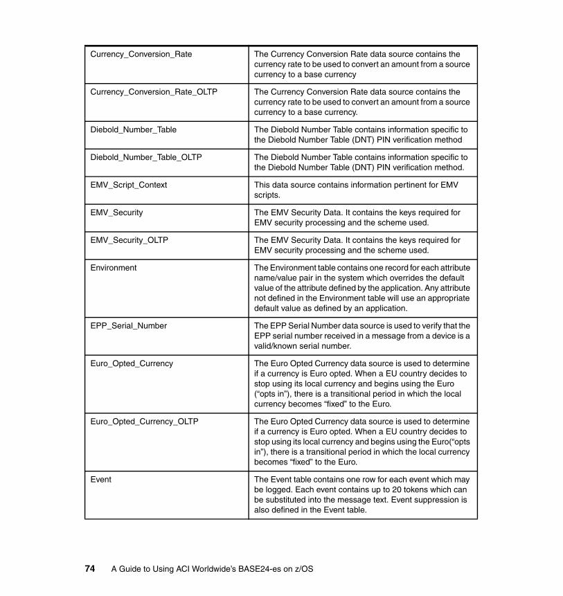
Currency_Conversion_Rate The Currency Conversion Rate data source contains the currency rate to be used to convert an amount from a source currency to a base currency
Currency_Conversion_Rate_OLTP The Currency Conversion Rate data source contains the currency rate to be used to convert an amount from a source currency to a base currency.
Diebold_Number_Table The Diebold Number Table contains information specific to the Diebold Number Table (DNT) PIN verification method
Diebold_Number_Table_OLTP The Diebold Number Table contains information specific to the Diebold Number Table (DNT) PIN verification method.
EMV_Script_Context This data source contains information pertinent for EMV scripts.
EMV_Security The EMV Security Data. It contains the keys required for EMV security processing and the scheme used.
EMV_Security_OLTP The EMV Security Data. It contains the keys required for EMV security processing and the scheme used.
Environment The Environment table contains one record for each attribute name/value pair in the system which overrides the default value of the attribute defined by the application. Any attribute not defined in the Environment table will use an appropriate default value as defined by an application.
EPP_Serial_Number The EPP Serial Number data source is used to verify that the EPP serial number received in a message from a device is a valid/known serial number.
Euro_Opted_Currency The Euro Opted Currency data source is used to determine if a currency is Euro opted. When a EU country decides to stop using its local currency and begins using the Euro (“opts in”), there is a transitional period in which the local currency becomes “fixed” to the Euro.
Euro_Opted_Currency_OLTP The Euro Opted Currency data source is used to determine if a currency is Euro opted. When a EU country decides to stop using its local currency and begins using the Euro(“opts in”), there is a transitional period in which the local currency becomes “fixed” to the Euro.
Event The Event table contains one row for each event which may be logged. Each event contains up to 20 tokens which can be substituted into the message text. Event suppression is also defined in the Event table.
74 A Guide to Using ACI Worldwide’s BASE24-es on z/OS
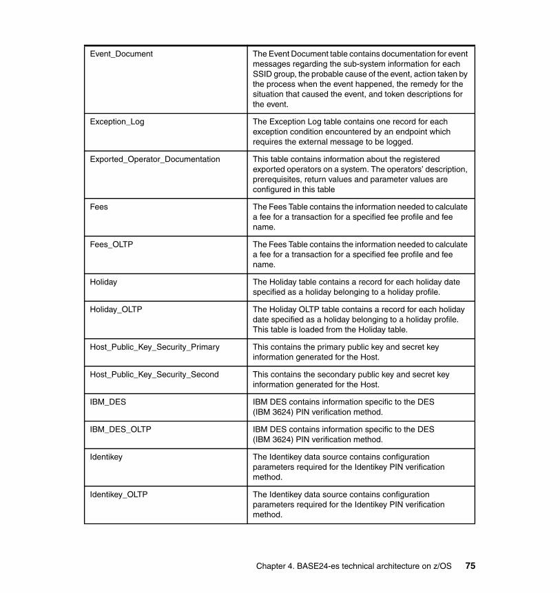
Event_Document The Event Document table contains documentation for event messages regarding the sub-system information for each SSID group, the probable cause of the event, action taken by the process when the event happened, the remedy for the situation that caused the event, and token descriptions for the event.
Exception_Log The Exception Log table contains one record for each exception condition encountered by an endpoint which requires the external message to be logged.
Exported_Operator_Documentation This table contains information about the registered exported operators on a system. The operators’ description, prerequisites, return values and parameter values are configured in this table
Fees The Fees Table contains the information needed to calculate a fee for a transaction for a specified fee profile and fee name.
Fees_OLTP The Fees Table contains the information needed to calculate a fee for a transaction for a specified fee profile and fee name.
Holiday The Holiday table contains a record for each holiday date specified as a holiday belonging to a holiday profile.
Holiday_OLTP The Holiday OLTP table contains a record for each holiday date specified as a holiday belonging to a holiday profile. This table is loaded from the Holiday table.
Host_Public_Key_Security_Primary This contains the primary public key and secret key information generated for the Host.
Host_Public_Key_Security_Second This contains the secondary public key and secret key information generated for the Host.
IBM_DES IBM DES contains information specific to the DES (IBM 3624) PIN verification method.
IBM_DES_OLTP IBM DES contains information specific to the DES (IBM 3624) PIN verification method.
Identikey The Identikey data source contains configuration parameters required for the Identikey PIN verification method.
Identikey_OLTP The Identikey data source contains configuration parameters required for the Identikey PIN verification method.
Chapter 4. BASE24-es technical architecture on z/OS 75
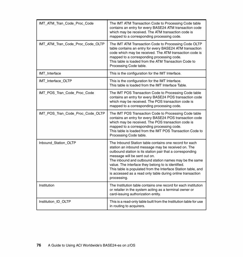
IMT_ATM_Tran_Code_Proc_Code The IMT ATM Transaction Code to Processing Code table contains an entry for every BASE24 ATM transaction code which may be received. The ATM transaction code is mapped to a corresponding processing code.
IMT_ATM_Tran_Code_Proc_Code_OLTP The IMT ATM Transaction Code to Processing Code OLTP table contains an entry for every BASE24 ATM transaction code which may be received. The ATM transaction code is mapped to a corresponding processing code. This table is loaded from the ATM Transaction Code to Processing Code table.
IMT_Interface This is the configuration for the IMT Interface.
IMT_Interface_OLTP This is the configuration for the IMT Interface.This table is loaded from the IMT Interface Table.
IMT_POS_Tran_Code_Proc_Code The IMT POS Transaction Code to Processing Code table contains an entry for every BASE24 POS transaction code which may be received. The POS transaction code is mapped to a corresponding processing code.
IMT_POS_Tran_Code_Proc_Code_OLTP The IMT POS Transaction Code to Processing Code table contains an entry for every BASE24 POS transaction code which may be received. The POS transaction code is mapped to a corresponding processing code. This table is loaded from the IMT POS Transaction Code to Processing Code table.
Inbound_Station_OLTP The Inbound Station table contains one record for each station an inbound message may be received on. The outbound station is its station pair that a corresponding message will be sent out on. The inbound and outbound station names may be the same value. The interface they belong to is identified. This table is populated from the Interface Station table, and is accessed as a read only table during online transaction processing.
Institution The Institution table contains one record for each institution or retailer in the system acting as a terminal owner or card-issuing authorization entity.
Institution_ID_OLTP This is a read-only table built from the Institution table for use in routing to acquirers.
76 A Guide to Using ACI Worldwide’s BASE24-es on z/OS
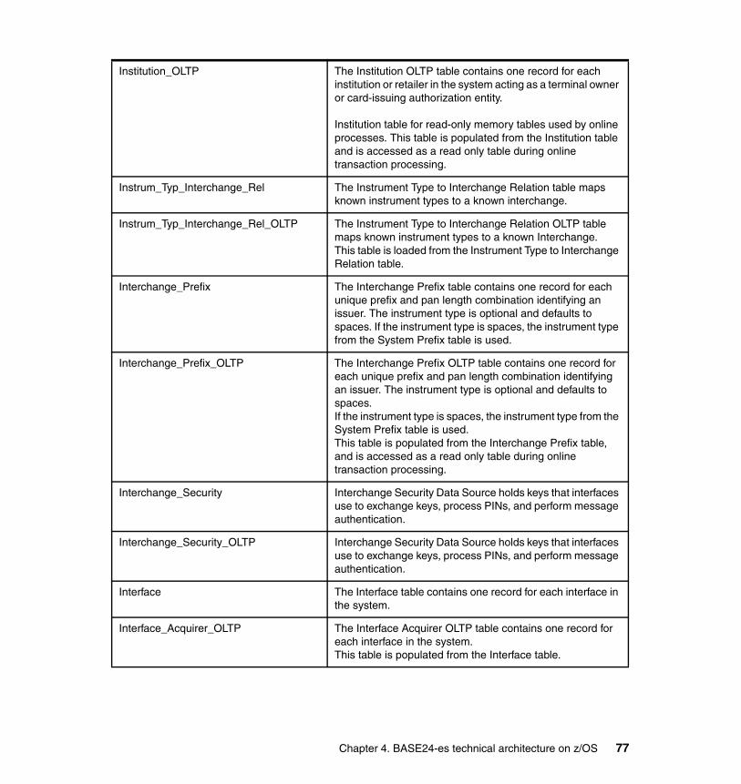
Institution_OLTP The Institution OLTP table contains one record for each institution or retailer in the system acting as a terminal owner or card-issuing authorization entity.
Institution table for read-only memory tables used by online processes. This table is populated from the Institution table and is accessed as a read only table during online transaction processing.
Instrum_Typ_Interchange_Rel The Instrument Type to Interchange Relation table maps known instrument types to a known interchange.
Instrum_Typ_Interchange_Rel_OLTP The Instrument Type to Interchange Relation OLTP table maps known instrument types to a known Interchange. This table is loaded from the Instrument Type to Interchange Relation table.
Interchange_Prefix The Interchange Prefix table contains one record for each unique prefix and pan length combination identifying an issuer. The instrument type is optional and defaults to spaces. If the instrument type is spaces, the instrument type from the System Prefix table is used.
Interchange_Prefix_OLTP The Interchange Prefix OLTP table contains one record for each unique prefix and pan length combination identifying an issuer. The instrument type is optional and defaults to spaces. If the instrument type is spaces, the instrument type from the System Prefix table is used. This table is populated from the Interchange Prefix table, and is accessed as a read only table during online transaction processing.
Interchange_Security Interchange Security Data Source holds keys that interfaces use to exchange keys, process PINs, and perform message authentication.
Interchange_Security_OLTP Interchange Security Data Source holds keys that interfaces use to exchange keys, process PINs, and perform message authentication.
Interface The Interface table contains one record for each interface in the system.
Interface_Acquirer_OLTP The Interface Acquirer OLTP table contains one record for each interface in the system. This table is populated from the Interface table.
Chapter 4. BASE24-es technical architecture on z/OS 77
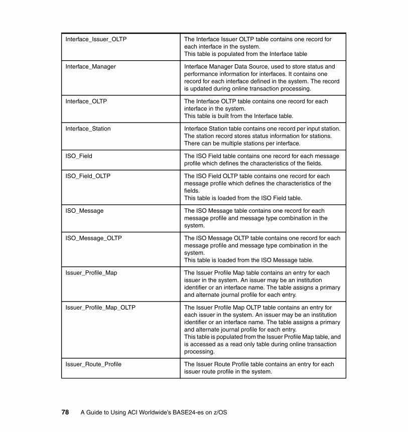
Interface_Issuer_OLTP The Interface Issuer OLTP table contains one record for each interface in the system. This table is populated from the Interface table
Interface_Manager Interface Manager Data Source, used to store status and performance information for interfaces. It contains one record for each interface defined in the system. The record is updated during online transaction processing.
Interface_OLTP The Interface OLTP table contains one record for each interface in the system. This table is built from the Interface table.
Interface_Station Interface Station table contains one record per input station. The station record stores status information for stations. There can be multiple stations per interface.
ISO_Field The ISO Field table contains one record for each message profile which defines the characteristics of the fields.
ISO_Field_OLTP The ISO Field OLTP table contains one record for each message profile which defines the characteristics of the fields. This table is loaded from the ISO Field table.
ISO_Message The ISO Message table contains one record for each message profile and message type combination in the system.
ISO_Message_OLTP The ISO Message OLTP table contains one record for each message profile and message type combination in the system. This table is loaded from the ISO Message table.
Issuer_Profile_Map The Issuer Profile Map table contains an entry for each issuer in the system. An issuer may be an institution identifier or an interface name. The table assigns a primary and alternate journal profile for each entry.
Issuer_Profile_Map_OLTP The Issuer Profile Map OLTP table contains an entry for each issuer in the system. An issuer may be an institution identifier or an interface name. The table assigns a primary and alternate journal profile for each entry. This table is populated from the Issuer Profile Map table, and is accessed as a read only table during online transaction processing.
Issuer_Route_Profile The Issuer Route Profile table contains an entry for each issuer route profile in the system.
78 A Guide to Using ACI Worldwide’s BASE24-es on z/OS

Issuer_Txn_Allowed The Issuer Transaction Allowed table contains one record for each issuer transaction profile, message category code and processing code in the system that are allowed. This table defines the set of transactions that are valid for an issuer for on-us and not-on-us transactions.
Issuer_Txn_Allowed_OLTP The Issuer Transaction Allowed table contains one record for each issuer transaction profile, message category code and processing code in the system that are allowed. This table defines the set of transactions that are valid for an issuer for on-us and not-on-us transactions. This table is populated from the Issuer Txn Allowed table and is accessed as a read only table during online transaction processing.
Journal This contains a record for each journaled transaction.
Journal_Continuation This contains 1 to n records when a transaction exceeds the storage capacity of the Journal file. The num_jrnl_rec represents the actual number of additional records required to journal the transaction.
Journal_Continuation_Assign The Journal Continuation Assign table contains one record for each journal continuation index entry. There should be, at a minimum, four assign names (one for previous, one for current, one for future and one for an empty file). The actual number of assigns is defined in the Journal Continuation Configuration table by adding the retention period (previous), future count plus two for the current and empty file.
Journal_Continuation_Assign_OLTP The Journal Continuation Assign OLTP table contains one record for each journal continuation index entry. There should be, at a minimum, four assign names (one for previous, one for current, one for future and one for an empty file). The actual number of assigns is defined in the Journal Continuation Configuration table by adding the retention period (previous), future count plus two for the current and empty file. This table is loaded from the Journal Continuation Assign table.
Journal_Continuation_Config The Journal Continuation Configuration table contains a row describing the journal continuation.
Journal_Data_Suppression The Journal Transaction Data Element Suppression table contains a record by Institution, message type, transaction code for each TDE Object ID NOT to journal. The message type and transaction code may be wildcarded with asterisks.
Chapter 4. BASE24-es technical architecture on z/OS 79

Journal_Data_Suppression_OLTP The Journal Transaction Data Element Suppression table contains a record by Institution, message type, transaction code for each TDE Object ID NOT to journal. The message type and transaction code may be wildcarded with asterisks. This table is populated from the Journal Data Suppression table, and is accessed as a read only table during online transaction processing.
Journal_Prfl_Group_Assign_OLTP The Journal Profile Group Assign OLTP table contains one record for each journal profile and index entry. There should be at minimum four assign names for each journal profile (one for previous, one for current, one for future and one for an empty file). The actual number of assigns is defined in the Journal Profile Group table by adding the retention period (previous), future count plus two for the current and empty file. This table is populated from the Journal Profile Group Assign table and is accessed as a read only table during online transaction processing.
Journal_Profile_Group The Journal Profile Group table contains a row for each journal profile in the system.
Journal_Profile_Group_Assign The Journal Profile Group Assign table contains one record for each journal profile and index entry. There should be, at a minimum, four assign names for each journal profile (one for previous, one for current, one for future and one for an empty file). The actual number of assigns is defined in the Journal Profile Group table by adding the retention period (previous), future count plus two for the current and empty file.
Journal_Profile_Group_OLTP The Journal Profile Group table contains a row for each journal profile in the system. This table is populated from the Journal Profile Group table, and is accessed as a read only table during online transaction processing.
Journal_Query_Config The Journal Query Configuration table contains a record for each Journal Batch Query that can be performed.
Journal_Query_Config_Output The Journal Query Configuration Output table contains a record for each Output location for a specific Journal Batch Query that can be performed. The Journal Query Output Profile specifies a a group of output files that are round-robined to determine the next group of files to write to.
80 A Guide to Using ACI Worldwide’s BASE24-es on z/OS

Journal_Query_Output_Assign The Journal Query Output Assign table contains one record for each journal profile and index entry. There should be at minimum one assign name for each journal profile. This table allows a journal query to exceed the capacity of a single file, and records will continue to be written to the next file if the first file fills up.
Journal_Query_Output_Map The Journal Query Output Map table contains an entry for each journal query output profile in the system. The table defines the ring of journal query profiles to use for a journal query.
Journal_Query_Position_Info The Journal Query Position Information table contains a record for each specific Journal Batch Query and Journal Profile combination that has retained position information used to continue a journal batch query.
Limits This table contains limits that are associated with a payment instrument (for example, card).
Limits_OLTP This table contains limits that are associated with a payment instrument (for example, card).
Linked_Currency The Linked Currency data source is used to determine if the transaction acquirer currency and cardholder billing currency are linked. Currencies are linked if the conversion rates and minor units for both currencies are the same.
Linked_Currency_OLTP The Linked Currency data source is used to determine if the transaction acquirer currency and cardholder billing currency are linked. Currencies are linked if the conversion rates and minor units for both currencies are the same.
MDS_Interface The MasterCard Debit Interface configuration data.
MDS_Interface_OLTP The MasterCard Debit Interface configuration data.
Merch_Instr_Typ_Relation The Merchant Instrument Type Relation table contains one record for each merchant and instrument type combination allowed that are not already specified in the Merchant Table.
Merch_Instr_Type_Relation_OLTP The Merchant Instrument Type Relation OLTP table contains one record for each merchant and instrument type combination allowed that are not already specified in the Merchant Table. This table is populated from the Merchant Instrument Type Relation table, and is accessed as a read only table during online transaction processing.
Chapter 4. BASE24-es technical architecture on z/OS 81
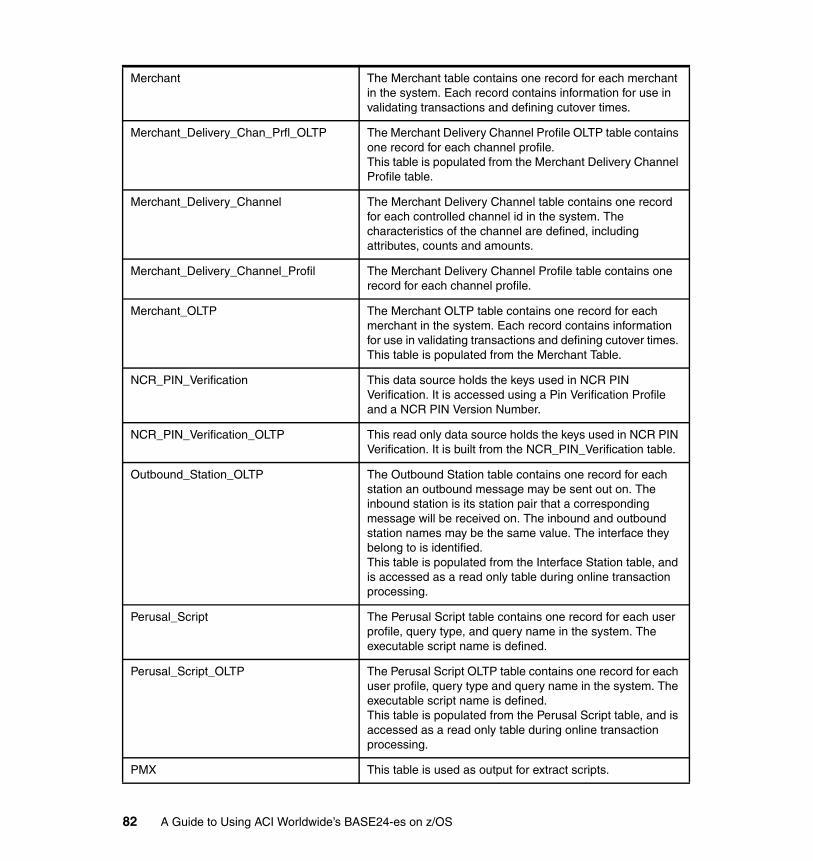
Merchant The Merchant table contains one record for each merchant in the system. Each record contains information for use in validating transactions and defining cutover times.
Merchant_Delivery_Chan_Prfl_OLTP The Merchant Delivery Channel Profile OLTP table contains one record for each channel profile. This table is populated from the Merchant Delivery Channel Profile table.
Merchant_Delivery_Channel The Merchant Delivery Channel table contains one record for each controlled channel id in the system. The characteristics of the channel are defined, including attributes, counts and amounts.
Merchant_Delivery_Channel_Profil The Merchant Delivery Channel Profile table contains one record for each channel profile.
Merchant_OLTP The Merchant OLTP table contains one record for each merchant in the system. Each record contains information for use in validating transactions and defining cutover times. This table is populated from the Merchant Table.
NCR_PIN_Verification This data source holds the keys used in NCR PIN Verification. It is accessed using a Pin Verification Profile and a NCR PIN Version Number.
NCR_PIN_Verification_OLTP This read only data source holds the keys used in NCR PIN Verification. It is built from the NCR_PIN_Verification table.
Outbound_Station_OLTP The Outbound Station table contains one record for each station an outbound message may be sent out on. The inbound station is its station pair that a corresponding message will be received on. The inbound and outbound station names may be the same value. The interface they belong to is identified. This table is populated from the Interface Station table, and is accessed as a read only table during online transaction processing.
Perusal_Script The Perusal Script table contains one record for each user profile, query type, and query name in the system. The executable script name is defined.
Perusal_Script_OLTP The Perusal Script OLTP table contains one record for each user profile, query type and query name in the system. The executable script name is defined. This table is populated from the Perusal Script table, and is accessed as a read only table during online transaction processing.
PMX This table is used as output for extract scripts.
82 A Guide to Using ACI Worldwide’s BASE24-es on z/OS
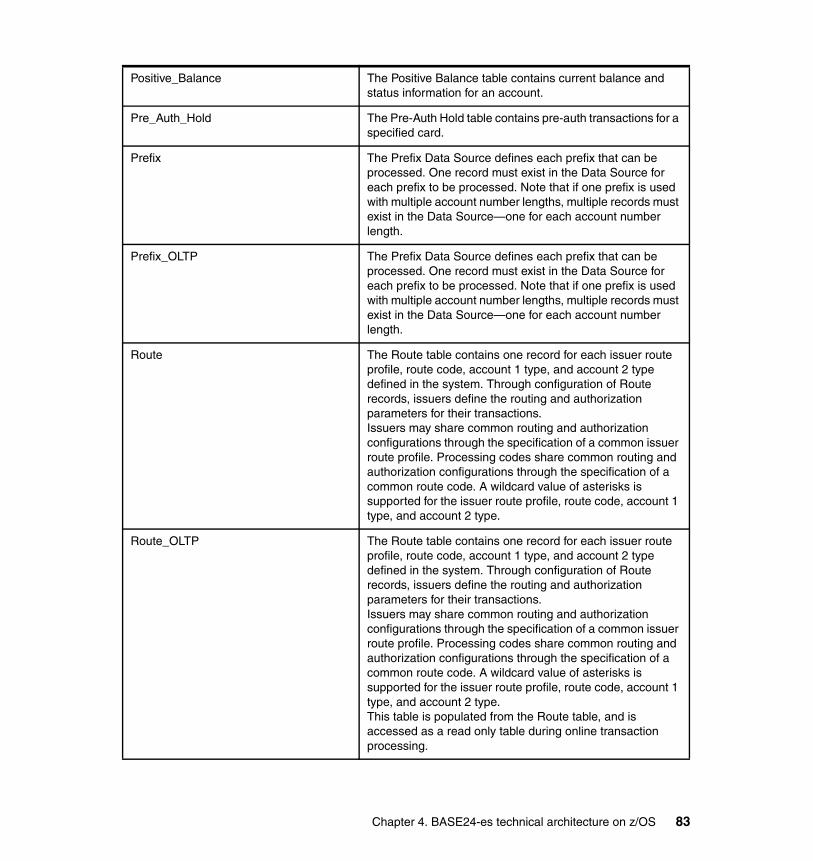
Positive_Balance The Positive Balance table contains current balance and status information for an account.
Pre_Auth_Hold The Pre-Auth Hold table contains pre-auth transactions for a specified card.
Prefix The Prefix Data Source defines each prefix that can be processed. One record must exist in the Data Source for each prefix to be processed. Note that if one prefix is used with multiple account number lengths, multiple records must exist in the Data Source—one for each account number length.
Prefix_OLTP The Prefix Data Source defines each prefix that can be processed. One record must exist in the Data Source for each prefix to be processed. Note that if one prefix is used with multiple account number lengths, multiple records must exist in the Data Source—one for each account number length.
Route The Route table contains one record for each issuer route profile, route code, account 1 type, and account 2 type defined in the system. Through configuration of Route records, issuers define the routing and authorization parameters for their transactions. Issuers may share common routing and authorization configurations through the specification of a common issuer route profile. Processing codes share common routing and authorization configurations through the specification of a common route code. A wildcard value of asterisks is supported for the issuer route profile, route code, account 1 type, and account 2 type.
Route_OLTP The Route table contains one record for each issuer route profile, route code, account 1 type, and account 2 type defined in the system. Through configuration of Route records, issuers define the routing and authorization parameters for their transactions. Issuers may share common routing and authorization configurations through the specification of a common issuer route profile. Processing codes share common routing and authorization configurations through the specification of a common route code. A wildcard value of asterisks is supported for the issuer route profile, route code, account 1 type, and account 2 type. This table is populated from the Route table, and is accessed as a read only table during online transaction processing.
Chapter 4. BASE24-es technical architecture on z/OS 83
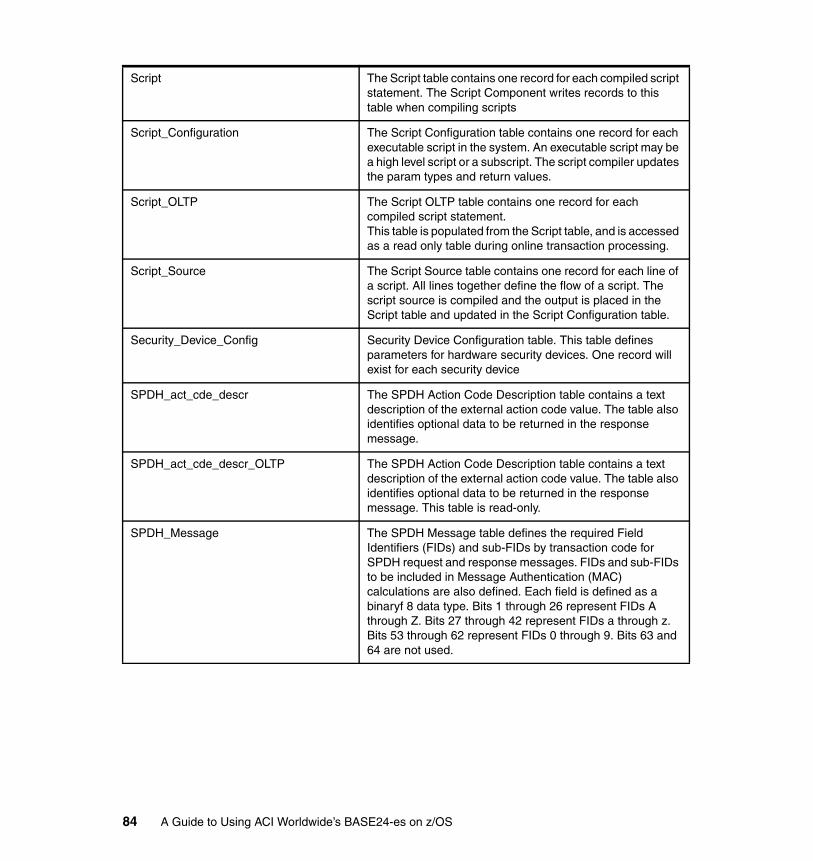
Script The Script table contains one record for each compiled script statement. The Script Component writes records to this table when compiling scripts
Script_Configuration The Script Configuration table contains one record for each executable script in the system. An executable script may be a high level script or a subscript. The script compiler updates the param types and return values.
Script_OLTP The Script OLTP table contains one record for each compiled script statement. This table is populated from the Script table, and is accessed as a read only table during online transaction processing.
Script_Source The Script Source table contains one record for each line of a script. All lines together define the flow of a script. The script source is compiled and the output is placed in the Script table and updated in the Script Configuration table.
Security_Device_Config Security Device Configuration table. This table defines parameters for hardware security devices. One record will exist for each security device
SPDH_act_cde_descr The SPDH Action Code Description table contains a text description of the external action code value. The table also identifies optional data to be returned in the response message.
SPDH_act_cde_descr_OLTP The SPDH Action Code Description table contains a text description of the external action code value. The table also identifies optional data to be returned in the response message. This table is read-only.
SPDH_Message The SPDH Message table defines the required Field Identifiers (FIDs) and sub-FIDs by transaction code for SPDH request and response messages. FIDs and sub-FIDs to be included in Message Authentication (MAC) calculations are also defined. Each field is defined as a binaryf 8 data type. Bits 1 through 26 represent FIDs A through Z. Bits 27 through 42 represent FIDs a through z. Bits 53 through 62 represent FIDs 0 through 9. Bits 63 and 64 are not used.
84 A Guide to Using ACI Worldwide’s BASE24-es on z/OS
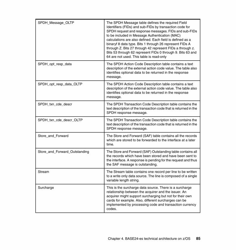
SPDH_Message_OLTP The SPDH Message table defines the required Field Identifiers (FIDs) and sub-FIDs by transaction code for SPDH request and response messages. FIDs and sub-FIDs to be included in Message Authentication (MAC) calculations are also defined. Each field is defined as a binaryf 8 data type. Bits 1 through 26 represent FIDs A through Z. Bits 27 through 42 represent FIDs a through z. Bits 53 through 62 represent FIDs 0 through 9. Bits 63 and 64 are not used. This table is read-only
SPDH_opt_resp_data The SPDH Action Code Description table contains a text description of the external action code value. The table also identifies optional data to be returned in the response message.
SPDH_opt_resp_data_OLTP The SPDH Action Code Description table contains a text description of the external action code value. The table also identifies optional data to be returned in the response message.
SPDH_txn_cde_descr The SPDH Transaction Code Description table contains the text description of the transaction code that is returned in the SPDH response message.
SPDH_txn_cde_descr_OLTP The SPDH Transaction Code Description table contains the text description of the transaction code that is returned in the SPDH response message.
Store_and_Forward The Store and Forward (SAF) table contains all the records which are stored to be forwarded to the interface at a later time.
Store_and_Forward_Outstanding The Store and Forward (SAF) Outstanding table contains all the records which have been stored and have been sent to the interface. A response is pending for the request and thus the SAF message is outstanding.
Stream The Stream table contains one record per line to be written to a write only data source. The line is composed of a single variable length string.
Surcharge This is the surcharge data source. There is a surcharge relationship between the acquirer and the issuer. An acquirer might support surcharging but not for their own cards for example. Also, different surcharges can be implemented by processing code and transaction currency codes.
Chapter 4. BASE24-es technical architecture on z/OS 85

Surcharge_OLTP This is the surcharge datasource. There is a surcharge relationship between the acquirer and the issuer. An acquirer might support surcharging but not for their own cards for example. Also, different surcharges can be implemented by processing code and transaction currency codes.
System_Algorithm_Config The System Algorithm Configuration table contains one record for each prefix/prefix range and pan length based on the algorithm name.
System_Algorithm_Config_OLTP The System Algorithm Configuration OLTP table contains one record for each prefix/prefix range and pan length based on the algorithm type. This table is populated from the System Algorithm Config table, and is accessed as a read only table during online transaction processing.
System_Prefix The System Prefix table contains one record for each unknown prefix to search based on Source Logical Network and Acquirer Route Profile to determine the correct issuer. The Acquirer Route Profile may be wildcarded.
System_Prefix_OLTP The System Prefix OLTP table contains one record for each unknown prefix to search based on Source Logical Network and Acquirer Route Profile to determine the correct issuer. The Acquirer Route Profile may be wildcarded. This table is populated from the System Prefix table, and is accessed as a read only table during online transaction processing.
TMX This table is used as output for extract scripts.
Usage This table contains the usages associated with a card, account or customer. The usages are checked against limits which are defined in the Limit Table.
User_Perusal_Prfl_Relation The User Perusal Profile Relation table contains one record for each alias which maps specific users to a user profile.
User_Perusal_Prfl_Relation_OLTP The User Perusal Profile Relation OLTP table contains one record for each alias which maps specific users to a user profile. This table is populated from the User Perusal Profile Relation table, and is accessed as a read only table during online transaction processing.
Visa_Interface The Visa Interface configuration data.
Visa_Interface_OLTP The Visa Interface configuration data.
86 A Guide to Using ACI Worldwide’s BASE24-es on z/OS
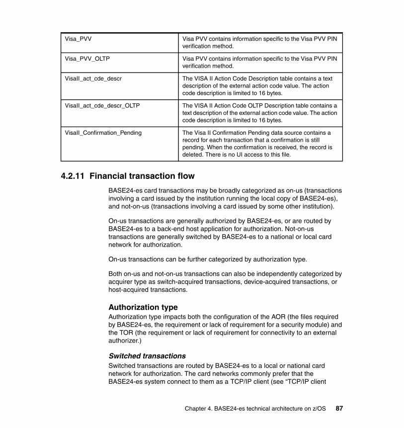
4.2.11 Financial transaction flow
BASE24-es card transactions may be broadly categorized as on-us (transactions involving a card issued by the institution running the local copy of BASE24-es), and not-on-us (transactions involving a card issued by some other institution).
On-us transactions are generally authorized by BASE24-es, or are routed by BASE24-es to a back-end host application for authorization. Not-on-us transactions are generally switched by BASE24-es to a national or local card network for authorization.
On-us transactions can be further categorized by authorization type.
Both on-us and not-on-us transactions can also be independently categorized by acquirer type as switch-acquired transactions, device-acquired transactions, or host-acquired transactions.
Authorization typeAuthorization type impacts both the configuration of the AOR (the files required by BASE24-es, the requirement or lack of requirement for a security module) and the TOR (the requirement or lack of requirement for connectivity to an external authorizer.)
Switched transactionsSwitched transactions are routed by BASE24-es to a local or national card network for authorization. The card networks commonly prefer that the BASE24-es system connect to them as a TCP/IP client (see “TCP/IP client
Visa_PVV Visa PVV contains information specific to the Visa PVV PIN verification method.
Visa_PVV_OLTP Visa PVV contains information specific to the Visa PVV PIN verification method.
VisaII_act_cde_descr The VISA II Action Code Description table contains a text description of the external action code value. The action code description is limited to 16 bytes.
VisaII_act_cde_descr_OLTP The VISA II Action Code OLTP Description table contains a text description of the external action code value. The action code description is limited to 16 bytes.
VisaII_Confirmation_Pending The Visa II Confirmation Pending data source contains a record for each transaction that a confirmation is still pending. When the confirmation is received, the record is deleted. There is no UI access to this file.
Chapter 4. BASE24-es technical architecture on z/OS 87
considerations” on page 51), though existing protocols provided in the z/OS implementation of BASE24-es by the VTAM reader/writer programs (see “VTAM considerations” on page 54) are commonly still supported.
Offline authorizationOffline transactions are transactions authorized by BASE24-es on the basis of data configured in its own database. They require no connectivity in the TOR to an external authorizer.
Online authorizationOnline transactions are transactions routed by BASE24-es to a back-end host application for authorization. On other platforms, connectivity to the back-end host application is generally accomplished by some variety of TCP/IP data communications.
Though this is also possible in the z/OS implementation of BASE24-es, it is generally preferable with a CICS-based host application to take advantage of the fact that BASE24-es and the back-end application are co-located, and use some CICS facility to communicate. BASE24-es supports several options natively; one desirable option is the use of a CICS LINK from the BASE24-es AOR to the back-end host AOR. However, connectivity is generally driven by the requirements of the back-end host system, and is often customized to meet those requirements.
With the Online authorization method, it is common for BASE24-es to perform some pre-screening such as Personal Identification Number (PIN) validation before passing the transaction to the back-end host application for authorization.
Online/Offline authorizationOnline/Offline authorization is the authorization method in which BASE24-es generally goes to a back-end host system for authorization, but is capable of standing in and performing authorization when the back-end host application is unavailable.
Considerations for communications with the back-end host application are the same as for Online Authorization described in “Online authorization” on page 88). Considerations for the authorization database in the AOR are similar to the considerations for Offline Authorization described in “Offline authorization” on page 88, although a less robust authorization method (perhaps declining hot cards rather than checking available balances) is often selected.
Acquirer typeThe Acquirer type generally has little direct impact on the configuration of the BASE24-es AOR other than the specific module within BASE24-es to which the
88 A Guide to Using ACI Worldwide’s BASE24-es on z/OS
external message is routed for parsing. It has more direct implications on the configuration of the TOR.
Device-acquired transactionsDevice-acquired transactions include transactions that originate from automated teller machine (ATM) and point of sale (POS) devices. They may include a mix of on-us and not-on-us transactions, and may be authorized by any of the authorization types.
ATM-acquired transactions generally enter the BASE24-es system through the BASE24-es TCP/IP Server Communications handler (see “TCP/IP server considerations” on page 52), though it is also common for transactions from older ATMs to enter the system through an existing protocol and the VTAM reader/writer transactions (see “VTAM considerations” on page 54).
POS devices have a wide variety of protocol requirements. In the z/OS implementation of BASE24-es, transactions from these devices commonly flow through an external protocol adapter and enter the BASE24-es system through the BASE24-es TCP/IP Server Communications handler as described in “TCP/IP server considerations” on page 52.
Switch-acquired transactionsSwitch-acquired transactions are transactions acquired from local or national card networks and routed to BASE24-es for authorization. They generally represent on-us transactions only and are authorized as one of the Online, Offline, or Online/Offline authorization types.
Connectivity to the card networks is generally through the BASE24-es TCP/IP Client Communications Handler (see “TCP/IP client considerations” on page 51), although existing protocols provided in the z/OS implementation of BASE24-es by the VTAM reader/writer tasks (see “VTAM considerations” on page 54) are commonly still supported.
Host-acquired transactionsHost-acquired transactions are usually transactions acquired by devices or card networks connected to a pre-existing host application and routed to BASE24-es for authorization or routing. Host-acquired transactions are most generally not-on-us transactions (since on-us transactions are often processed by the pre-existing host application itself), but may be a mix of switched and offline transactions.
On other platforms, connectivity to the acquiring host application is generally accomplished by some variety of TCP/IP data communications. Though this is also possible in the z/OS implementation of BASE24-es, it is generally preferable with a CICS-based host application to take advantage of the fact that BASE24-es
Chapter 4. BASE24-es technical architecture on z/OS 89

and the back-end application are co-located, and use some CICS facility to communicate. Connectivity is generally driven by the requirements of the acquiring host system, and is almost always customized to meet those requirements.
4.2.12 BASE24-es logical architecture on z/OS
Figure 4-18 is the original picture of the BASE24-es logical architecture, with components re-labeled to reflect the implementation-specific component that provides the logical services.
Figure 4-18 BASE24-es logical architecture
4.2.13 User interface region architecture
The BASE24-es User Interface consists of an HTTP client, an HTTP server, and CICS-based server components. The HTTP server runs on a Windows© or pSeries® front-end, and communicates with the CICS-based servers over TCP/IP.
External Endpoints
CICS Sockets/VTAMProtocol &Middleware
Application
Database CICS/SMSVSAM Manager
VSAM/RLS Database
Base24-es Communication Handlers
CICS TDQ/WebSphere MQ
Memory-Based Queues
Automated Teller Machines
Point of Sale Devices
Host Acquiring or Authorization
Public Card Networks
BASE24-es Integrated Server
BASE24-es System Interface Services
BASE24-es Integrated Server
BASE24-es System Interface Services
BASE24-es Integrated Server
BASE24-es System Interface Services
90 A Guide to Using ACI Worldwide’s BASE24-es on z/OS
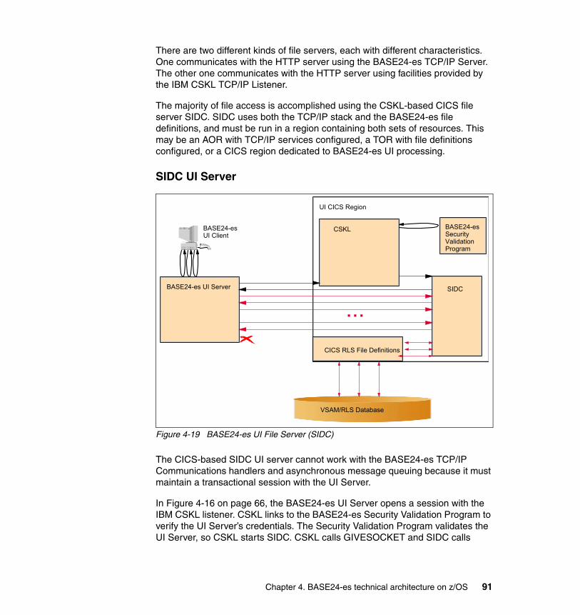
There are two different kinds of file servers, each with different characteristics. One communicates with the HTTP server using the BASE24-es TCP/IP Server. The other one communicates with the HTTP server using facilities provided by the IBM CSKL TCP/IP Listener.
The majority of file access is accomplished using the CSKL-based CICS file server SIDC. SIDC uses both the TCP/IP stack and the BASE24-es file definitions, and must be run in a region containing both sets of resources. This may be an AOR with TCP/IP services configured, a TOR with file definitions configured, or a CICS region dedicated to BASE24-es UI processing.
SIDC UI Server
Figure 4-19 BASE24-es UI File Server (SIDC)
The CICS-based SIDC UI server cannot work with the BASE24-es TCP/IP Communications handlers and asynchronous message queuing because it must maintain a transactional session with the UI Server.
In Figure 4-16 on page 66, the BASE24-es UI Server opens a session with the IBM CSKL listener. CSKL links to the BASE24-es Security Validation Program to verify the UI Server’s credentials. The Security Validation Program validates the UI Server, so CSKL starts SIDC. CSKL calls GIVESOCKET and SIDC calls
BASE24-es UI Client
CSKL
CICS RLS File Definitions
VSAM/RLS Database
UI CICS Region
BASE24-es UI Server
BASE24-es Security Validation Program
SIDC
...
Chapter 4. BASE24-es technical architecture on z/OS 91
TAKESOCKET, so SIDC becomes the owner of the socket established by the UI Server. SIDC then sends a good response to the UI Server.
The UI Server now sends a BEGINTRANSACTION message to establish transactional boundaries around the database updates to follow. SIDC combines all subsequent updates into a single database transaction until the UI Server calls ENDTRANSACTION, at which time SIDC performs a sync point.
The SIDC task persists until the client connection is lost. If the connection is lost within the boundaries of a database transaction, SIDC rolls back any database updates in progress before terminating.
XMLS UI serverThe CICS-based XMLS UI Server is a special instance of the BASE24-es Integrated Server used to route BASE24-es Process Control commands to the Integrated Server, and to provide C++ facilities to access certain specially-formatted data in some BASE24-es data files.
It has no special database transactional considerations and operates similarly to the BASE24-es Integrated Server; the user interface connects with the BASE24-es TCP/IP Server, which places messages destined for the XMLS server on an associated TDQ.
92 A Guide to Using ACI Worldwide’s BASE24-es on z/OS

Figure 4-20 BASE24-es UI Application Server (XMLS)
In Figure 4-20 the UI Client sends a BASE24-es Process Control command to the UI Server. The UI Server sends the request to a BASE24-es TCP/IP Server running in the TOR.
The TCP/IP server starts the AOR Routing Program XDYR and XDYR places the transaction on the XMLS TDQ.
XMLS reformats the UI message as an IS Process Control message and places the message on the IS TDQ. (Note that in BASE24-es Version 06.2, all Process Control messages can be processed equivalently by any member of a server class.)
The Integrated Server processes the request and places a response on the XMLS TDQ (see “TCP/IP connected security module” on page 61 for details or synchronous messages between BASE24-es components.) XMLS reformats the response and places it on the TCP/IP Communication Handler’s TDQ for delivery to the client.
BASE24-es UI Client
XMLSTDQ
BASE24-es UI Server
BASE24-es IP Server
TOR
IPTDQ
ISTDQ
XDYR
XMLS
IS
AOR
Chapter 4. BASE24-es technical architecture on z/OS 93
4.2.14 Scalability considerations
The following discussion deals with replication for scalability. Replication for availability receives a separate discussion in a subsequent chapter.
Replicating TORsBASE24-es TCP/IP Communications Handlers may be replicated within a TOR, and TORs may be replicated within a CICSPlex or other MRO environment.
TCP/IP Client Communications Handlers may be freely replicated. For example, though it would rarely be necessary from a throughput perspective, multiple TCP/IP Clients in multiple TORs might be configured to communicate with a single remote endpoint, say a large public card network. Each TCP/IP handler is configured with its own symbolic name, and is defined to the application as a separate routable endpoint.
TCP/IP Server Communications Handlers may be replicated within limits imposed by the sockets API. Specifically, the sockets API does not permit two listeners at the same IP address to bind to and accept connections on the same TCP port. Network routers, z/OS Shared Sockets or z/OS Virtual IP Addressing may be used to permit multiple TCP/IP Servers to share the same IP address and TCP port.
BASE24-es IP Communications Handlers (Client or Server) may be distributed across any number of TORs and LPARs subject to the above considerations.
Replicating AORsBASE24-es AORs may be freely replicated. As BASE24-es will attempt to distribute work evenly across available AORs, consideration should be given to defining more AORs in LPARs with more available resources.
Replicating tasksBASE24-es Integrated Server tasks can and should be replicated within an AOR. The MAXSERVERS parameter in the BASE24-es System Interface Services Message Delivery SDMF configuration file controls the number of tasks created in each AOR.
There is little overhead associated with configuring an ample number of tasks. As a rule of thumb, there is no excessive overhead if half the instances of a server class are in an ECK_WAIT state during a period of relatively high activity.
94 A Guide to Using ACI Worldwide’s BASE24-es on z/OS
Partitioning filesBASE24-es provides several mechanisms for logically partitioning some of the most intensively-used files for purposes of scalability. This is provided in addition to file-system level partitioning.
Financial Journal File partitioningFinancial Journal (JRNL) files can be partitioned across institutions. It is also possibly to further partition the JRNL files associated with a given institution by card range, minimizing the possibility that inserts to the JRNL will become a hard bottleneck.
Card and Usage file partitioningCard and usage files can be logically partitioned by card range, minimizing contention on these files.
Interface file partitioningThe SAF, Interface Manager, and Interface Station files may be partitioned by interface, minimizing lock contention in these files.
Replicating LPARsBASE24-es may be distributed across multiple Logical Partitions (LPARs) in a Parallel Sysplex. The Parallel Sysplex may be distributed across multiple physical processing units. The only requirement is that all the context-free servers in a BASE24-es system must have a common database in which to hold their shared context.
Benchmark observationsACI Worldwide and IBM conducted a benchmark from November 7-18, 2005, at the IBM Washington Systems Center to demonstrate the performance characteristics of BASE24-es on the latest IBM System z9. The objective was to achieve a processor consumption rate competitive with other solutions of this type, and to maintain virtually constant MIPS per transaction rates as volumes increased to a throughput of over 1000 transactions per second. The effort met or exceeded these objectives.
� Performance and scalability were close to linear, while the cost per transaction remained low and constant.
� The test achieved more than 1000 transactions per second on 8 CPUs (limited only by I/O capacity). This represents twice the daily peak volume requirements of the world’s largest transaction processors.
� System z9 performance can satisfy any customer’s requirements with near linear MIPS per transaction. TCO per transaction becomes lower with higher transaction volumes as support costs are fairly constant as volume grows.
Chapter 4. BASE24-es technical architecture on z/OS 95
In addition, BASE24-es clients who run the solution on the IBM System z9 mainframe can take full advantage of the other benefits of the mainframe platform, such as superior security, utilization rates of over 90%, dynamic workload balancing for improved efficiencies, virtually unlimited scalability, superior performance and a system designed for continuous operations.
WSC Benchmark scalability test – single LPARTest configuration: z/OS 1.6VSAM 1.6 CICS TS CPSM 2.3Storage subsystem 2105-800 8 LSS LPAR configurations 2094-701 1 CPU
2094-702 2 CPU2094-704 4 CPU2094-708 8 CPU
Coupling Facility (2) 2094-701 1 CPU eachCICS statistics on (all), interval 5 minutesRMF statistics on sys(notype(032,089,099),interval(500), nodetail)
subsys(stc, type(000:018,020:255, interval(500))
Results:Test results are summarized in Figure 4-21 on page 97. Throughput (transactions per second) and cost (MIPS per transaction) data was captured for each of four LPAR configurations: 1, 2, 4 and 8 CPUs. MIPS per transaction remained constant through approximately 1018 transactions per second, where the I/O subsystem became saturated.
The solid upper line shows transactions per second, while the dotted lower line shows that MIPS per transaction remained nearly constant as the transaction rate increased. (Absolute CPU utilization and MIPS cost are not shown. For accurate sizing information, contact ACI.)
96 A Guide to Using ACI Worldwide’s BASE24-es on z/OS

Figure 4-21 Benchmark result
WSC Benchmark scalability test – dual LPARTest configuration: z/OS 1.6VSAM 1.6 CICS TS 2.3, CPSM 2.3Storage subsystem 2105-800 8 LSS LPAR configuration (2)2094-704 4 CPU eachCoupling Facility (2) 2094-7011 CPU eachCICS statistics on (all), interval 5 minutesRMF statistics on sys(notype(032,089,099),interval(500), nodetail)
subsys(stc, type(000:018,020:255, interval(500))
Results:Test results are summarized in Figure 4-22 on page 98. Two 4-CPU LPARs processed approximately the same throughput as a single 8-CPU LPAR (again limited by I/O capacity), but the MIPS per transaction was slightly higher and non-linear (15% at 1072 TPS).
The solid upper line shows transactions per second, while the dotted lower line shows that MIPS per transaction increased only slightly as the transaction rate increased. (Absolute CPU utilization and MIPS cost are not shown. For accurate sizing information, contact ACI.)
CPSM - Single LPAR
1018
764
431
230
0
200
400
600
800
1000
1200
1 2 4 8
Transactions per second
MIPS per transaction
Tran
sact
ions
per
Sec
ond
MIP
S p
er T
rans
actio
n
CPU Busy
Number of CPUs
Chapter 4. BASE24-es technical architecture on z/OS 97
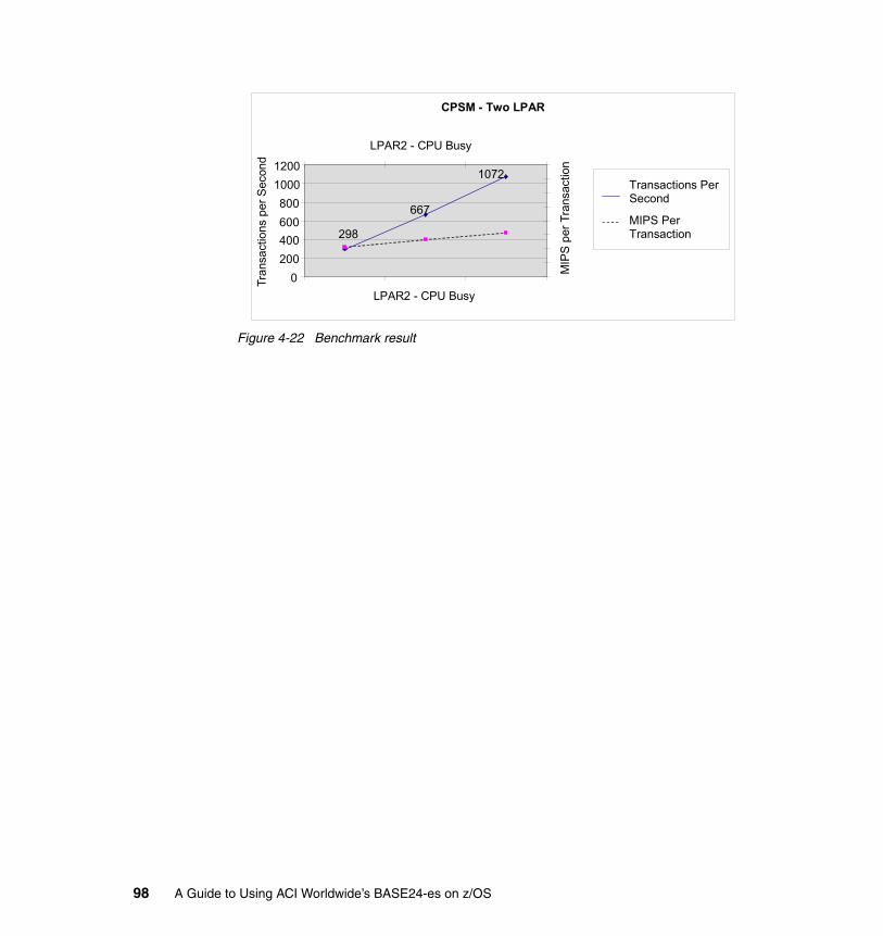
Figure 4-22 Benchmark result
CPSM - Two LPAR
298
667
1072
0 200 400 600 800
1000 1200
Transactions Per Second
MIPS Per Transaction
Tran
sact
ions
per
Sec
ond
MIP
S pe
r Tra
nsac
tion
LPAR2 - CPU Busy
LPAR2 - CPU Busy
98 A Guide to Using ACI Worldwide’s BASE24-es on z/OS
Chapter 5. Designing the system layout
Most customers consider the implementation of e-payment systems like BASE24-es to be among their mission-critical applications. And for mission-critical applications, availability is a very significant business requirement.
In this chapter, we explain the high availability characteristics of each BASE24-es component. We also show you four possible options for configuring BASE24-es when running under CICS and z/OS.
5
© Copyright IBM Corp. 2006. All rights reserved. 99
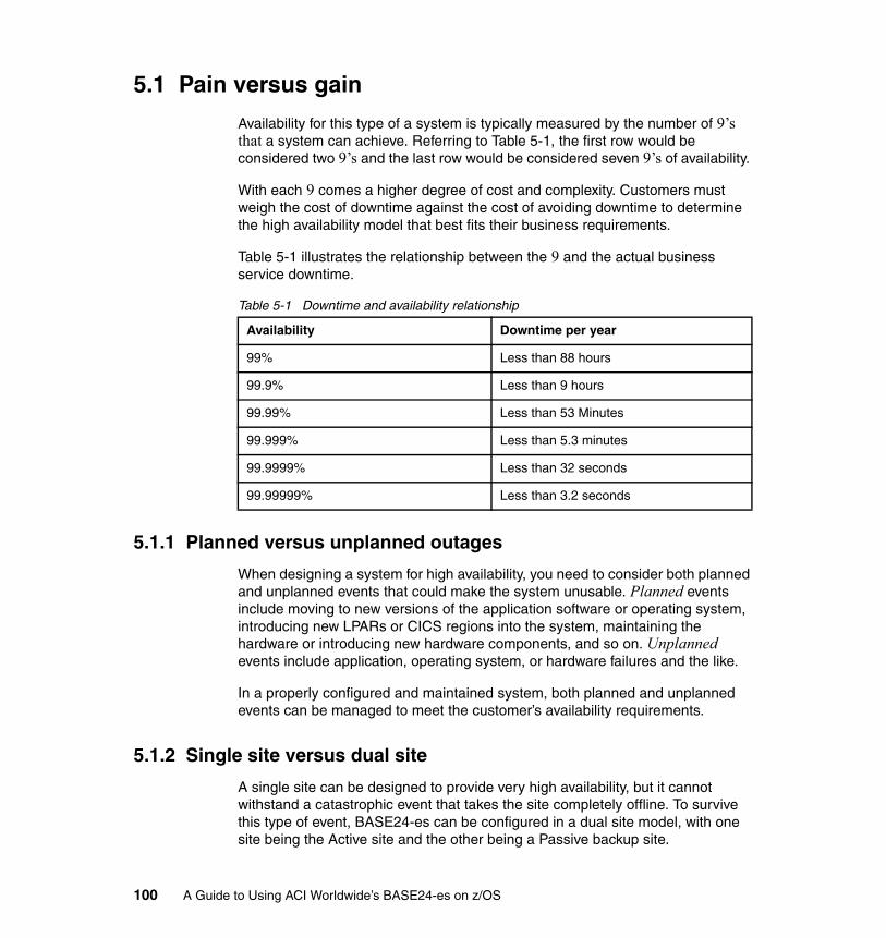
5.1 Pain versus gain
Availability for this type of a system is typically measured by the number of 9’s that a system can achieve. Referring to Table 5-1, the first row would be considered two 9’s and the last row would be considered seven 9’s of availability.
With each 9 comes a higher degree of cost and complexity. Customers must weigh the cost of downtime against the cost of avoiding downtime to determine the high availability model that best fits their business requirements.
Table 5-1 illustrates the relationship between the 9 and the actual business service downtime.
Table 5-1 Downtime and availability relationship
5.1.1 Planned versus unplanned outages
When designing a system for high availability, you need to consider both planned and unplanned events that could make the system unusable. Planned events include moving to new versions of the application software or operating system, introducing new LPARs or CICS regions into the system, maintaining the hardware or introducing new hardware components, and so on. Unplanned events include application, operating system, or hardware failures and the like.
In a properly configured and maintained system, both planned and unplanned events can be managed to meet the customer’s availability requirements.
5.1.2 Single site versus dual site
A single site can be designed to provide very high availability, but it cannot withstand a catastrophic event that takes the site completely offline. To survive this type of event, BASE24-es can be configured in a dual site model, with one site being the Active site and the other being a Passive backup site.
Availability Downtime per year
99% Less than 88 hours
99.9% Less than 9 hours
99.99% Less than 53 Minutes
99.999% Less than 5.3 minutes
99.9999% Less than 32 seconds
99.99999% Less than 3.2 seconds
100 A Guide to Using ACI Worldwide’s BASE24-es on z/OS
In this model, there are two copies of the BASE24-es data and data replication software. They are used to keep the data synchronized. If a failure occurs at the primary site, the backup site can be activated to take over the processing. This model is also useful during large-scale planned events, such as moving a data center.
5.2 High availability considerations
In the following sections, we list considerations to keep in mind to enable the BASE24-es solution to achieve a high level of availability.
5.2.1 Terminal Owning Regions (TORs)
To provide high availability in a BASE24-es system, two or more Terminal Owning Regions (TORs) are required. Redundant TCP/IP Server connections should be configured across multiple TORs. BASE24-es is designed to use round robin processing across all available TCP/IP Server connections. It detects when connections are lost and re-established. TCP/IP Clients utilize Virtual IP to connect to BASE24-es.
VirtualizationThere are two virtualization strategies available when configuring BASE24-es. The first takes advantage of an ATM or point of sale (POS) device’s capability to have a primary and alternate destination configured. The second strategy is to provide Virtual IP Addressing (VIPA), a router, Sysplex Distributor, or a combination of those.
Primary/Alternate configurationFigure 5-1 on page 102 illustrates a primary/alternate configuration. In the figure, note that half of the devices are configured with a primary destination of 1.2.3.4, port 8000 and a secondary destination of 1.2.3.5, port 8000. The other half of the devices are configured with primary destination of 1.2.3.5, port 9000 and a secondary destination of 1.2.3.4, port 9000.
There is a separate TOR responsible for listening on each of the ports. The TORs are spread across the two LPARs. The TORs are configured such that the primary and secondary destination for all terminals will reside in different LPARs.
Chapter 5. Designing the system layout 101
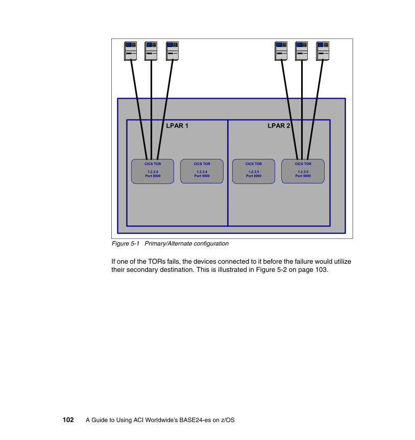
Figure 5-1 Primary/Alternate configuration
If one of the TORs fails, the devices connected to it before the failure would utilize their secondary destination. This is illustrated in Figure 5-2 on page 103.
LPAR 1
CICS TOR
1.2.3.4 Port 8000
LPAR 2
CICS TOR
1.2.3.5 Port 8000
CICS TOR
1.2.3.4 Port 9000
CICS TOR
1.2.3.5 Port 9000
102 A Guide to Using ACI Worldwide’s BASE24-es on z/OS
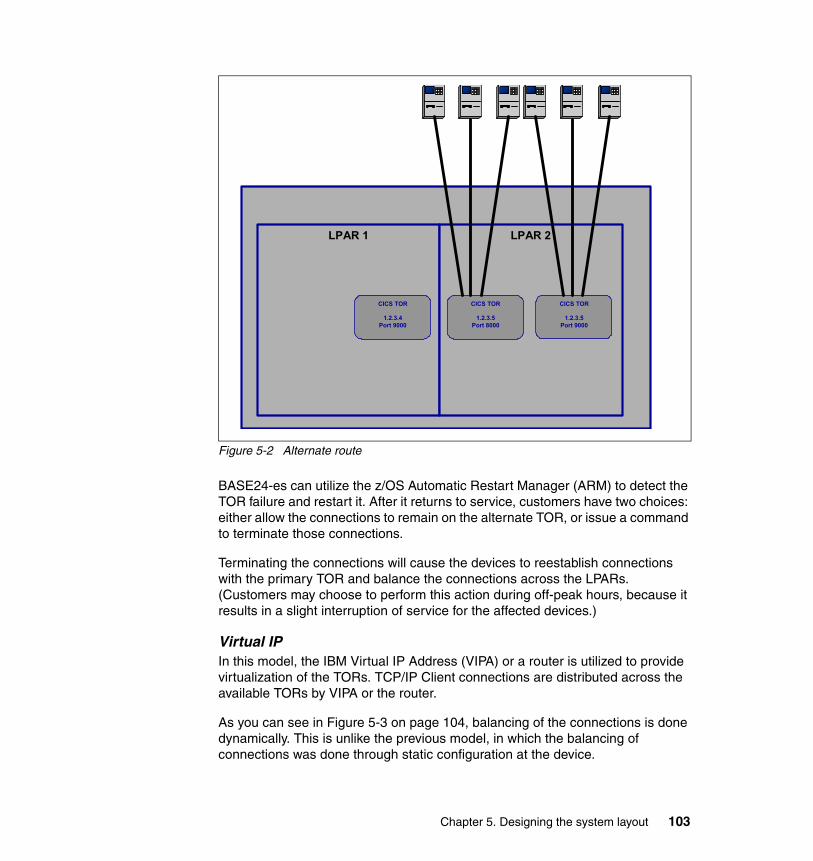
Figure 5-2 Alternate route
BASE24-es can utilize the z/OS Automatic Restart Manager (ARM) to detect the TOR failure and restart it. After it returns to service, customers have two choices: either allow the connections to remain on the alternate TOR, or issue a command to terminate those connections.
Terminating the connections will cause the devices to reestablish connections with the primary TOR and balance the connections across the LPARs. (Customers may choose to perform this action during off-peak hours, because it results in a slight interruption of service for the affected devices.)
Virtual IPIn this model, the IBM Virtual IP Address (VIPA) or a router is utilized to provide virtualization of the TORs. TCP/IP Client connections are distributed across the available TORs by VIPA or the router.
As you can see in Figure 5-3 on page 104, balancing of the connections is done dynamically. This is unlike the previous model, in which the balancing of connections was done through static configuration at the device.
LPAR 1 LPAR 2
CICS TOR
1.2.3.5 Port 8000
CICS TOR
1.2.3.4 Port 9000
CICS TOR
1.2.3.5 Port 9000
Chapter 5. Designing the system layout 103
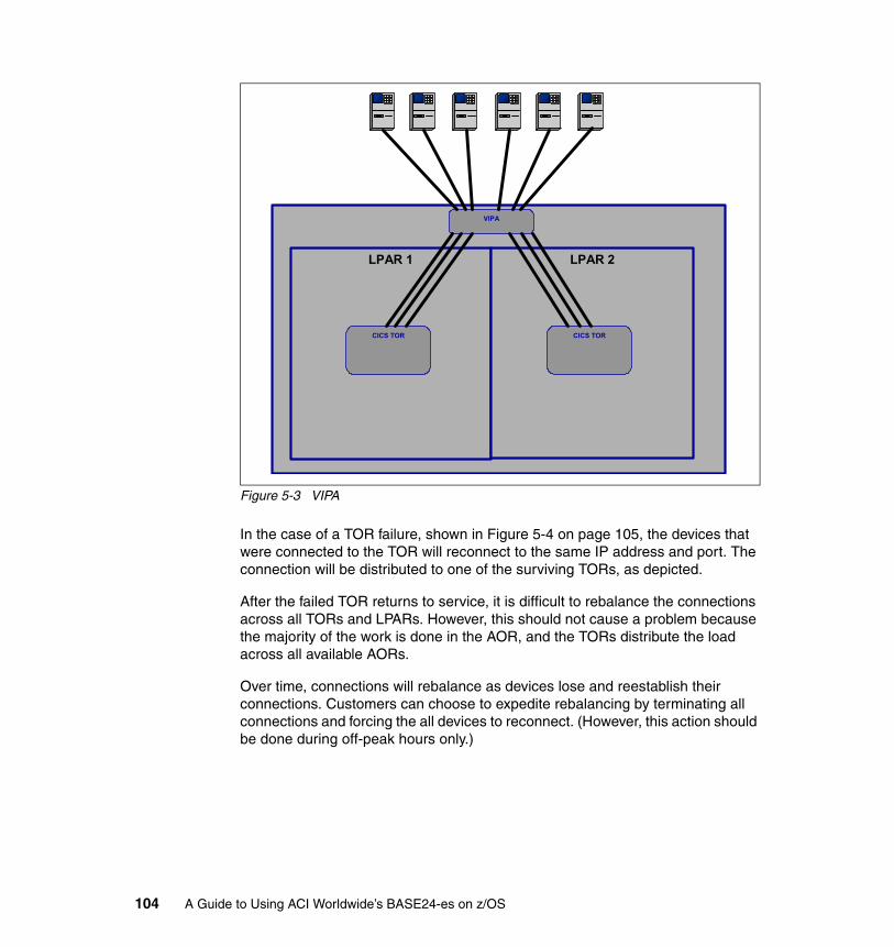
Figure 5-3 VIPA
In the case of a TOR failure, shown in Figure 5-4 on page 105, the devices that were connected to the TOR will reconnect to the same IP address and port. The connection will be distributed to one of the surviving TORs, as depicted.
After the failed TOR returns to service, it is difficult to rebalance the connections across all TORs and LPARs. However, this should not cause a problem because the majority of the work is done in the AOR, and the TORs distribute the load across all available AORs.
Over time, connections will rebalance as devices lose and reestablish their connections. Customers can choose to expedite rebalancing by terminating all connections and forcing the all devices to reconnect. (However, this action should be done during off-peak hours only.)
LPAR 1
CICS TOR
LPAR 2
CICS TOR
VIPA
104 A Guide to Using ACI Worldwide’s BASE24-es on z/OS
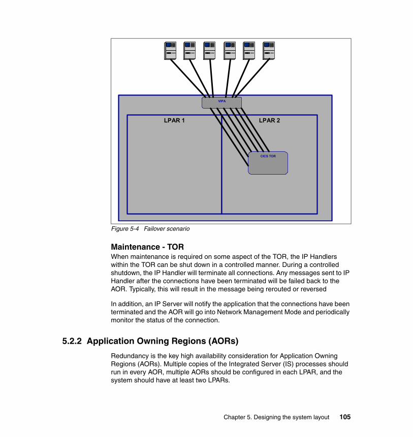
Figure 5-4 Failover scenario
Maintenance - TORWhen maintenance is required on some aspect of the TOR, the IP Handlers within the TOR can be shut down in a controlled manner. During a controlled shutdown, the IP Handler will terminate all connections. Any messages sent to IP Handler after the connections have been terminated will be failed back to the AOR. Typically, this will result in the message being rerouted or reversed
In addition, an IP Server will notify the application that the connections have been terminated and the AOR will go into Network Management Mode and periodically monitor the status of the connection.
5.2.2 Application Owning Regions (AORs)
Redundancy is the key high availability consideration for Application Owning Regions (AORs). Multiple copies of the Integrated Server (IS) processes should run in every AOR, multiple AORs should be configured in each LPAR, and the system should have at least two LPARs.
LPAR 1 LPAR 2
CICS TOR
VIPA
Chapter 5. Designing the system layout 105
Integrated Server failureIn the unlikely event that an IS fails, the surviving IS tasks will continue to deal with the messages. The BASE24-es Task Monitor is responsible for detecting an IS failure and restarting it.
AOR failureIn the event of an AOR failure, the TORs rely on the Dynamic Transaction Routing Program in a CICSPlex environment, and routing user exit in a non-CICSPlex environment, to detect and route around the AOR failure. The few transactions that were on the TDQ at the time of the failure will be lost. BASE24-es relies on the end-to-end protocols built into the electronic payment industry to deal with the transaction appropriately.
z/OS Automatic Restart Manager (ARM) can be used to quickly restart the AOR after a failure. Refer to 4.2.10, “AOR architecture” on page 56 for an in-depth discussion about starting the AOR.
Maintenance - AOROccasionally, maintenance will be required on the AOR. This could take two forms, either maintenance to the Integrated Servers, or maintenance to the AOR itself. This section describes how maintenance can be performed on the AOR without disrupting service.
Integrated Server maintenanceBASE24-es provides a mechanism to stop and restart all IS processes in turn. This mechanism is useful when introducing new IS software or when bringing in new configuration data.
AOR maintenanceWhen AOR maintenance is necessary, the AOR can be shut down in a controlled manner. When a shutdown is required, the AOR will notify the TOR that it should no longer be considered in the AOR selection process. This will stop new work from being added to the TDQ. After all messages on the TDQ have been processed, the Integrated Servers will be stopped and the AOR will be terminated.
After maintenance is complete, the AOR can be restarted. Refer to 4.2.10, “AOR architecture” on page 56 for an in-depth discussion of starting the AOR.
5.2.3 File access
In the following sections, we discuss the high availability considerations for the files environment.
106 A Guide to Using ACI Worldwide’s BASE24-es on z/OS
Data sharing Data sharing is the concept that applications running in different CICS regions can share access to data, no matter which z/OS image in a sysplex they happen to be running on. Ideally, all CICS AORs should be able to access all of the data needed to run any transaction. If you have only one system image, you should find it easy to achieve this access.
If you have two or more z/OS system images in your sysplex, however, you may have to implement specific levels of database or access method software to enable all AORs to access the same data at the same time, no matter which z/OS system the AOR is running in. DFSMS (SMSVSAM), in conjunction with CICS TS, provides similar facilities for VSAM data sets.
Multiple CICS/ESA® applications in a CICSplex can share VSAM data sets with integrity by using function shipping to a single FOR. This approach has limitations, though. It does not solve the problem of the FOR being a single point of unavailability. Other CICS applications outside the Parallel Sysplex can also use the FOR by function shipping over ISC links. DFSMS provides RLS access for VSAM files. CICS TS allows CICS users to exploit this function. RLS is designed to allow VSAM data to be shared, with full update integrity, among many applications running in many CICS regions in one or more z/OS system images in a Parallel Sysplex.
The SMSVSAM server runs in its own address space and handles all VSAM requests made in RLS mode. If this address space fails, it can be restarted automatically up to six times, assuming RLSINIT=YES is specified in the IGDSMSxx member that the host z/OS image uses. The most likely reason for an SMSVSAM server failure is loss of connectivity to the Coupling Facility.
The SMSVSAM address space fails if it cannot rebuild a Coupling Facility lock structure, if it loses connectivity to the Coupling Facility lock structure, or if the Coupling Facility lock structure fails. The SMSVSAM address space also fails when it loses the last active SHaring Control Data Sets (SHCDS) and has no spare available.
When the SMSVSAM address space fails, any I/O against a VSAM data set open in RLS mode, or any attempt to open a VSAM data set in RLS mode, receives an error indicating that the SMSVSAM is unavailable. CICS detects that SMSVSAM address space is unavailable when one of the transactions attempts an RLS access.
When this event occurs, CICS issues message DFHFC0153: File control RLS access is being closed down. The effect that this has varies, depending on where individual tasks are in their life cycle.
Chapter 5. Designing the system layout 107
A typical transaction accesses several records in VSAM data sets and then performs either an implicit or explicit sync point. Statistically, a task is most likely to discover the failure of the SMSVSAM address space when it next attempts to read from or write to an RLS mode VSAM data set. It is less likely that a task discovers that SMSVSAM has failed when it tries to sync point and releases its locks in the VSAM data set.
Because SMSVSAM fails if it loses connectivity to the Coupling Facility lock structure, consider having more than one Coupling Facility. The possibility of SMSVSAM server failure is minimized if you have two or more Coupling Facilities.
Coupling Facilities A Coupling Facility (CF) is a special LPAR that provides high-speed caching, list processing, and locking functions in a Parallel Sysplex. The LPAR can be configured to run within a CP that runs other operating systems (it is often referred to as an ICF in this case), or it could be configured in a stand-alone processor that only runs Coupling Facility Control Code (CFCC).
It is important to understand the difference between a CF and an operating system LPAR. If an operating system LPAR dies, all work that was running in that system is dead and must be restarted.
On the other hand, depending on which structures are in a CF that suffers a failure, it is possible that only a short pause in processing will be encountered as the CF contents are rebuilt in an alternate CF.
As a result, it is possible that a CF will not be impacted by a failure to the same degree as an operating system. More importantly, from an availability perspective, is whether the structures in the failed CF support rebuild and duplexing, and whether the failure impacted any connected systems or not.
Maximizing availability of CF serviceIn this section we provide a set of recommendations to maximize the availability of the CF service. We also touch on performance, because good performance is especially important for a CF, and poor CF performance can be disruptive for the systems connected to it.
In order to be able to deliver acceptable response times, you must have enough capacity in your CFs. In addition to CF CPU utilization, you must also consider response times. It is possible for CF CPU utilization to be low, but with CF response times so long that the cost of using the CF becomes unacceptable (this is especially the case if there is a large disparity in speed between the CF CPC and the CPCs that the operating systems are running on).
108 A Guide to Using ACI Worldwide’s BASE24-es on z/OS
Regardless of the type of link being used, you need to configure for the following qualities:
� Availability
You need at least two links between each pair of CPCs (at a minimum). CF links can be shared using Multiple Image Facility (MIF). However, there can only be one CF LPAR sharing a given “end” of a link, and the operating system LPARs sharing a link must all be in the same sysplex. Remember that if you share a link between multiple LPARs, the loss of that link will impact all those LPARs.
� Performance
In the early days of Parallel Sysplex, two CF links provided sufficient capacity for most users. Now the intensiveness with which CFs are being used has increased to the point that in many sites, two CF links are no longer sufficient.
However, the rule of thumb for PATH BUSY and SUBCHANNEL BUSY remains the same: both PATH BUSY and the number of requests delayed because of SUBCHANNEL BUSY should not exceed 10 percent of the number of requests.
In addition, subchannel utilization (calculated by multiplying the number of requests on the subchannel by the average response time, divided by the number of seconds in the interval) should not exceed 30%. Ensure that you configure sufficient links so that these thresholds are not exceeded during peak processing windows.
� Avoid single points of failure
There should be as few single points of failure as possible in common between the links used to connect a set of LPARs. When you order CF links, the configuration provided will normally do the best to avoid single points of failure.
Failure isolation One of the most important characteristics of a CF is its location in relation to the systems that are connected to it. There are some advantages to it being in a stand-alone processor. However, the most important question is whether a single failure can impact both the CF and one or more systems connected to it.
A CF in a CPC where none of the other images in that CPC are connected to that CF can provide nearly as good availability as one running in a stand-alone processor. Many structures can be rebuilt even if there is a double failure.
However, some of the most important structures in a data sharing environment cannot recover from such a failure without a data sharing group restart (unless the structure is duplexed). To determine your need for a failure-isolated CF, review the structures you use to see if any of them fall into that category.
Chapter 5. Designing the system layout 109
Structure placement Structures that have a failure isolation requirement should either be placed in a failure-isolated CF (normally a stand-alone CF), or else they should be duplexed. Another thing to beware of is structures ending up in a CF other than the one you intended. This can happen, for example, following CF maintenance if the correct procedures are not followed to return the structures to their intended CF.
To avoid this situation, regularly verify that all structures are actually in the first available CF in their PREFLIST. One way to do this is by using the z/OS Health Checker, which has a check for this condition. In addition, consider issuing a SETXCF START,REBUILD,POPCF=cfname for each of your CFs on a regular basis. This will ensure that all structures are in the first CF in their PREFLIST (all other things being equal).
Never use a REBUILDPERCENT greater than 1. REBUILDPERCENT can be used to stop a structure being moved in case of a partial connectivity failure. However, with the speed of modern CF technology, it would be very rare that you would not want to move a structure following a connectivity failure. For simplicity, the best thing is just to not use that keyword at all—the default is to always rebuild a structure following such a failure.
Recovering from CF failure As stated previously, CFs are different from operating system LPARs in that if a CF fails, it is possible that the CF contents can be recreated in an alternate CF, allowing operations to continue with just a pause in processing. When planning for CF recovery, you need to consider whether the structures in the failed CF support recovery from a CF failure, and whether the remaining CFs have sufficient capacity to take over from the failed CF.
Structure recovery Whether a structure can recover from a CF failure or not depends on the exploiter that uses that structure, and whether it supports structure rebuild or duplexing.
Structure rebuild There are two flavors of structure rebuild: User-managed rebuild and system-managed rebuild.
Exploiters that support user-managed rebuild can generally recreate the structure contents following the failure of a CF or one of the connectors. However, in some cases they cannot recover from a double failure. Exploiters that only support system-managed rebuild cannot recreate the structure contents following a CF failure.
User-managed rebuild, which is supported by most of the earlier CF exploiters, means that the address spaces connected to a structure take responsibility for moving a
110 A Guide to Using ACI Worldwide’s BASE24-es on z/OS
structure in case of a planned move, or of recovering the structure in case of an unplanned move (failure of a CF, for example). Most exploiters that support user-managed rebuild maintain an in-storage copy of their data from the structure, meaning that even if the CF containing the structure is lost, they can still create a new version by merging all their in-storage information.
System-managed rebuild, introduced with OS/390® 2.8 and CF level 8, makes it significantly easier for products to avail themselves of the facilities provided by a CF. Whereas the connector is responsible for moving a structure when using user-managed rebuild, the operating system takes over that role when using system-managed rebuild. In this case, the connected operating systems work together to copy the contents of a structure from one CF to another. The systems have no knowledge of the meaning of the contents of the structure; they just copy the structure in its entirety.
Structure duplexing Similarly, there are two flavors of structure duplexing, which are User-managed duplexing and System-Managed CF Structure Duplexing.
User-managed duplexing is only used by DB2, and then only for its Group Buffer Pool structures. System-Managed CF Structure Duplexing is supported for any structure whose connectors support system-managed rebuild.
Both types of structure duplexing provide the ability to continue processing following a failure (assuming there is no single point of failure between the CFs containing the two copies of the structure). We describe both types in more detail in the following sections.
User-managed structure duplexing User-managed structure duplexing was introduced in OS/390 R3 with APAR OW28460, and was integrated into OS/390 R6. This capability is used by DB2 for its group buffer pool structures.
With user-managed duplexing, setting up the second structure, maintaining synchronization between the structures, and recovering from structure-related failures is the responsibility of the connector (DB2, in this case). Turning on user-managed duplexing for a DB2 GBP structure introduces very little additional overhead, but delivers significant benefits in terms of reduced recovery time if the GBP structure is lost.
Chapter 5. Designing the system layout 111
System-Managed CF Structure Duplexing System-Managed CF Structure Duplexing was announced as part of z/OS 1.2, with support in CF level 11 and later. With System-Managed CF Structure Duplexing, the operating system takes responsibility for setting up a duplex copy of a CF structure, maintaining the duplex relationship, and reverting back to simplex mode in the event of a CF or CF link failure.
Assuming that the two copies of a duplexed structure are failure-isolated from each other, the use of System-Managed CF Structure Duplexing for a structure allows you to place a structure in the same failure domain as one or more of its connectors, but still be protected from a single failure that would otherwise cause a data sharing group restart. However, while System-Managed CF Structure Duplexing provides substantial availability benefits, it can also have a significant impact on the response time for update requests to the duplexed structures.
Number of Coupling Facilities As a general rule, you should always have at least two Coupling Facilities. There are a small number of structures whose loss does not have a significant impact on the sysplex (OPERLOG and LOGREC are two examples), but in most cases, the loss of a structure will have some negative or disabling effect on the connected systems. Therefore, it is vital to always have an alternative CF available for a structure to rebuild into in the case of a planned or unplanned CF outage. This is why we recommend that every Parallel Sysplex has at least two CFs, even if you are only exploiting the Resource Sharing capability of the sysplex.
Some larger customers, especially those doing extensive exploitation of data sharing and those that have very high availability requirements, are now starting to deploy three CFs in their production Parallel Sysplexes. This provides greater capacity to cope with unexpected workload spikes, and ensures that there is still no single point of failure, even if one CF is unavailable for some reason.
Note: Whatever number of CFs you have, make sure that all of them are specified on the PREFLIST for all critical structures.
CF maintenance procedures There are different approaches to emptying Coupling Facilities.
One method that some customers use is to maintain three sets of CFRM policies: One that contains both CFs, one that contains just one CF, and one that contains just the other. To empty a CF, they switch to the policy containing just the CF that will remain in service, and then rebuild all the structures that now have a POLICY CHANGE PENDING status.
112 A Guide to Using ACI Worldwide’s BASE24-es on z/OS
Another method is to simply issue a SETXCF START,RB,CFNM=cfname,LOC=OTHER for the CF that is to be emptied. If you do this, you will need to move any XCF structures out of the CF with individual SETXCF START,RB commands.
After the work has been completed and the CF LPAR is activated and available to all systems, always use the SETXCF START,RB,POPCF=cfname command to repopulate the CF.
Whatever method you use, ensure the following:
� Maintain a well-documented and understood procedure for emptying the CF in question and then re-populating it following the changes, as it may be necessary from time to time to take a CF offline to implement hardware or microcode changes.
� Before handing over the CF to the service representative, verify that the CF is empty. Then configure off the CF links from all systems to the affected CF, and deactivate that CF LPAR on the Hardware Management Console (HMC).
Direct Access Storage Device (DASD)In order to protect your data environment, you might consider using DASD designed for the most demanding, mission-critical environments requiring extremely high availability, performance, and scalability. Any DASD subsystem supporting the RAID-5 and RAID-10 architecture can provide the needed infrastructure for the DASD subsystem.
For example, the IBM DS8000™ series is designed to avoid single points of failure and provide outstanding availability. With the additional advantages of IBM FlashCopy®, data availability can be enhanced even further; for instance, production workloads can continue execution concurrent with data backups. Metro Mirror and Global Mirror business continuity solutions are designed to provide the advanced functionality and flexibility needed to tailor a business continuity environment for almost any recovery point or recovery time objective. The addition of IBM solution integration packages spanning a variety of heterogeneous operating environments offers even more cost-effective ways to implement business continuity solutions.
Business continuity means that business processes and business-critical applications need to be available at all times. Therefore, it is very important to have a storage environment that offers resiliency across both planned and unplanned outages.
The DS8000 supports a rich set of Copy Service functions and management tools that can be used to build solutions to help meet business continuance requirements. These include IBM TotalStorage® Resiliency Family Point-in-Time
Chapter 5. Designing the system layout 113

Copy and Remote Mirror and Copy solutions, which are currently supported by the Enterprise Storage Server.
FlashCopy can help reduce or eliminate planned outages for critical applications. FlashCopy is designed to provide the same point-in-time copy capability for logical volumes on the DS6000™ series and the DS8000 series as FlashCopy V2 does for ESS, and it allows access to the source data and the copy almost immediately.
5.2.4 External system connectivity
Another consideration when designing a BASE24-es system for high availability is the connectivity to external systems such as the card association networks, regional or international switches, and external host systems. Connectivity loss to any one of these systems could result in the perception of a system outage or a failure to meet service level agreements.
BASE24-es overcomes this by simply allowing multiple connections to be configured to each of the external systems. The interfaces to the external systems use round robin processing across all available connections, resulting in load balancing across all connections.
If a connection is lost, the interface will mark the connection as down and will no longer send messages to it. The interface will periodically check the connection to see if it has been re-established. Once re-established, the interface will begin sending messages to the connection.
5.2.5 Back-end authorization system connectivity
When a CICS-based Host Application is available to provide authorization services to the payment engine, BASE24-es provides a Host Interface that can perform CICS LINKs to the Host Application. There are two methods used communicate with such an application. The first is to use distributed links, and the other is to statically configure the links. We discuss these methods in the following sections.
Distributed linksIn a CICSPlex environment, a customer can achieve high availability by taking advantage of the CICSPlex Workload Manager (WLM) to distribute the CICS LINK from BASE24-es across multiple Host Application target regions. In order to do this, the BASE24-es Host Interface must be configured in Synchronous mode.
There should be one entry configured in the Station Table for the Host Interface. That entry should correspond to an entry the SYDMF that defines the CICS
114 A Guide to Using ACI Worldwide’s BASE24-es on z/OS
program name of the Host Application. The CICS program should be configured as DYNAMIC, and the CICSPlex workload must be defined accordingly.
Statically configured linksIn a CICSPlex or other Multi-Region Operations (MRO) environment, an alternative approach to high availability is to rely on BASE24-es to distribute the CICS LINK across the available target regions. To accomplish this, once again, the BASE24-es Host Interface must be configured in Synchronous mode.
There should multiple entries in the Station Table, each corresponding to an entry in the SYDMF. There should be one SYDMF entry defining the CICS program name of the Host Application in each target region, which must be unique. Each remote program definition in the routing region must be associated with the corresponding target region.
The BASE24-es Host Interface will utilize the stations in turn, which will provide a load balancing effect. If a target region is unavailable, BASE24-es Alternate Routing can be configured to re-route the request to a second or third target region for authorization.
5.3 BASE24-es configurations
IBM supports many different ways to configure CICS applications. When configuring CICS applications, however, both technical configuration issues and business considerations must be taken into account. Among those business considerations is impact to users, cardholders, and account holders when the system is unavailable.
In this section we examine the possible options to configure BASE24-es when running under CICS and z/OS:
� Single LPAR� Multiple LPARs, single CPC� Multiple LPARs, multiple CPCs,� Multiple LPARs, multiple CPCs, dual site
These options are not meant to be all-encompassing. Instead, they highlight details to consider when planning a BASE24-es configuration.
Of course, there are many other considerations (cost of hardware, costs associated with ongoing maintenance and support of the configuration, requirements of other CICS applications, and so on) to be aware of when planning such a configuration, but they are beyond the scope of this redbook.
Chapter 5. Designing the system layout 115

The configuration options we describe progress from the most simplistic to the more complex. As mentioned, while the technical issues are a consideration when determining the appropriate configuration for BASE24, the business requirements cannot be ignored. Customers typically consider the implementation of an e-payment systems like BASE24-es to be a mission-critical application, and availability is a very significant business requirement. Therefore, the primary focus of the options is the availability of BASE24-es to process transactions
Each option includes a description of the configuration and a discussion of the single points of failure associated with the option.
5.3.1 Single LPAR
The first option is BASE24-es running in a single LPAR. The diagram in Figure 5-5 on page 117 shows a typical configuration for this option with one TOR, and with two AORs utilizing a single set of data files.
The number of both TORs and AORs can be expanded to provide greater resilience and throughput. This option uses VIPA to provide virtualization of the data communications.
116 A Guide to Using ACI Worldwide’s BASE24-es on z/OS
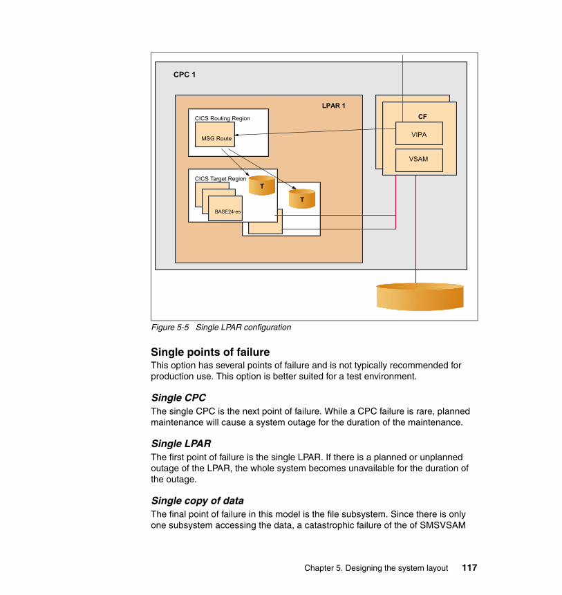
Figure 5-5 Single LPAR configuration
Single points of failureThis option has several points of failure and is not typically recommended for production use. This option is better suited for a test environment.
Single CPCThe single CPC is the next point of failure. While a CPC failure is rare, planned maintenance will cause a system outage for the duration of the maintenance.
Single LPARThe first point of failure is the single LPAR. If there is a planned or unplanned outage of the LPAR, the whole system becomes unavailable for the duration of the outage.
Single copy of dataThe final point of failure in this model is the file subsystem. Since there is only one subsystem accessing the data, a catastrophic failure of the of SMSVSAM
CICS Routing Region
CPC 1
MSG Route
LPAR 1 CF
VSAM
VIPA
BASE24-es
CICS Target RegionT
T
CF
VSAM
VIPA
Chapter 5. Designing the system layout 117
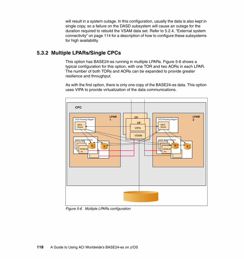
will result in a system outage. In this configuration, usually the data is also kept in single copy, so a failure on the DASD subsystem will cause an outage for the duration required to rebuild the VSAM data set. Refer to 5.2.4, “External system connectivity” on page 114 for a description of how to configure these subsystems for high availability.
5.3.2 Multiple LPARs/Single CPCs
This option has BASE24-es running in multiple LPARs. Figure 5-6 shows a typical configuration for this option, with one TOR and two AORs in each LPAR. The number of both TORs and AORs can be expanded to provide greater resilience and throughput.
As with the first option, there is only one copy of the BASE24-es data. This option uses VIPA to provide virtualization of the data communications.
Figure 5-6 Multiple LPARs configuration
CPC
CF
VSAM
VIPA
CF
VSAM
VIPA
CICS Routing Region
MSG Route
LPAR 2
BASE24-es
CICS Target Region
T T
CICS Routing Region
MSG Route
LPAR 1
BASE24-es
CICS Target Region
T T
118 A Guide to Using ACI Worldwide’s BASE24-es on z/OS
Single points of failureThis option provides greater availability than the previous option. It has some of the same points of failure, but nevertheless will satisfy the availability needs of many BASE24-es customers.
Single CPCThe single CPC can represent a single point of failure. While a CPC failure is rare, planned maintenance will cause a system outage for the duration of the maintenance.
Single copy of dataThe final point of failure in this model is the file subsystem. Because there is only one copy of the data, a catastrophic failure of the DASD subsystem will result in a system outage. Refer to 5.2.4, “External system connectivity” on page 114 for a description of how to configure these subsystems for high availability.
5.3.3 Multiple LPARs/Multiple CPCs
This option has BASE24-es running in multiple LPARs across multiple CPCs. Figure 5-7 on page 120 shows a typical configuration for this option, with one TOR and two AORs in each LPAR, and one LPAR in each CPC. The number of TORs, AORs, and LPARs can be expanded to provide greater resilience and throughput.
As with the first two options, there is only one copy of the BASE24-es data. This option uses VIPA to provide virtualization of the data communications.
Chapter 5. Designing the system layout 119
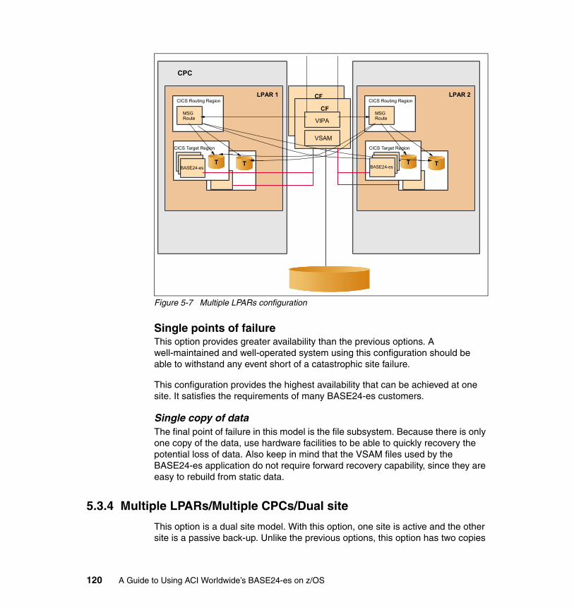
Figure 5-7 Multiple LPARs configuration
Single points of failureThis option provides greater availability than the previous options. A well-maintained and well-operated system using this configuration should be able to withstand any event short of a catastrophic site failure.
This configuration provides the highest availability that can be achieved at one site. It satisfies the requirements of many BASE24-es customers.
Single copy of dataThe final point of failure in this model is the file subsystem. Because there is only one copy of the data, use hardware facilities to be able to quickly recovery the potential loss of data. Also keep in mind that the VSAM files used by the BASE24-es application do not require forward recovery capability, since they are easy to rebuild from static data.
5.3.4 Multiple LPARs/Multiple CPCs/Dual site
This option is a dual site model. With this option, one site is active and the other site is a passive back-up. Unlike the previous options, this option has two copies
CPC
CF
VSAM
VIPA
CF
VSAM
VIPA
CICS Routing Region
MSG Route
LPAR 2
CICS Target Region
T T
CICS Routing Region
MSG Route
LPAR 1
BASE24-es
CICS Target Region
T T BASE24-es
120 A Guide to Using ACI Worldwide’s BASE24-es on z/OS
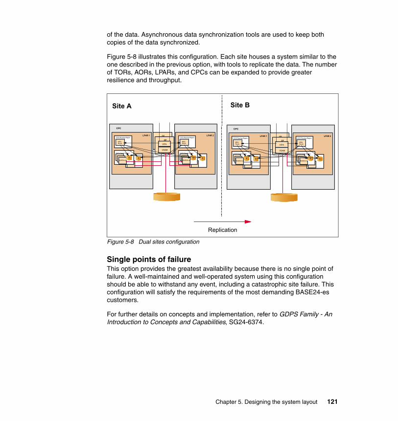
of the data. Asynchronous data synchronization tools are used to keep both copies of the data synchronized.
Figure 5-8 illustrates this configuration. Each site houses a system similar to the one described in the previous option, with tools to replicate the data. The number of TORs, AORs, LPARs, and CPCs can be expanded to provide greater resilience and throughput.
Figure 5-8 Dual sites configuration
Single points of failureThis option provides the greatest availability because there is no single point of failure. A well-maintained and well-operated system using this configuration should be able to withstand any event, including a catastrophic site failure. This configuration will satisfy the requirements of the most demanding BASE24-es customers.
For further details on concepts and implementation, refer to GDPS Family - An Introduction to Concepts and Capabilities, SG24-6374.
CPC
CF
VSAM
VIPA
CF
VSAM
VIPA
CICS Routing Region
MSG Route
LPAR 2
BASE24-es
CICS Target Region
T T
CICS Routing Region
MSG Route
LPAR 1
BASE24-es
CICS Target Region
T T
CPC
CF
VSAM
VIPA
CF
VSAM
VIPA
CICS Routing Region
MSG Route
LPAR 2
BASE24-es
CICS Target Region
T T
CICS Routing Region
MSG Route
LPAR 1
BASE24-es
CICS Target Region
T T
Site A Site B
Replication
Chapter 5. Designing the system layout 121

122 A Guide to Using ACI Worldwide’s BASE24-es on z/OS
Chapter 6. Installing BASE24-es on z/OS
In this chapter, we describe our target configuration environment. We explain the hardware/software requirements for BASE24-es, and describe the pre-installation steps needed for a successful installation of BASE24-es on z/OS.
The chapter covers the following topics:
� The ITSO environment
� BASE24-es hardware and software requirements
� An overview of the pre-installation steps
� Installation considerations
� How to set up integration with the back-end system
6
© Copyright IBM Corp. 2006. All rights reserved. 123
6.1 The ITSO environment
Our hardware setup complied with the requirement for maximum availability of the BASE24-es application on z/OS. We used a POS device simulator as a device-acquiring endpoint to acquire the transaction from the POS, and a Visa DPS networks simulator for acquiring transactions from Visa Debit Processing Service (DPS). IP protocol was used for communication. We did not test communication availability in this environment, but we used a Sysplex Distributor for connection balancing and availability. The primary goal in the environment was to provide high availability to the solution.
6.1.1 Hardware we used
Figure 6-1 on page 125 summarizes our hardware testing environment. The environment consisted of three LPARs: two running on the same Central Processor Complex (CPC), and one running on a different CPC within the same Parallel Sysplex. On each LPAR, there was a Terminal Owning Region (TOR) running with three cloned Application Owning Regions (AORs).
CICSplex System Manager (CP/SM) and BASE24-es were used to provide the dynamic routing capability from each TOR to all the AORs.
All the AORs were capable of accessing the VSAM files in Record Level Sharing (RLS) mode through the SMSVSAM address space. SMSVSAM allocates the cache and lock structure in the two Coupling Facilities available to the Parallel Sysplex.
The ACI desktop client was the user interface to BASE24-es.
124 A Guide to Using ACI Worldwide’s BASE24-es on z/OS
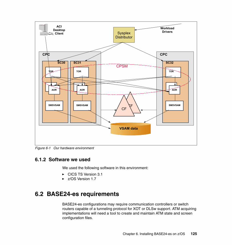
Figure 6-1 Our hardware environment
6.1.2 Software we used
We used the following software in this environment:
� CICS TS Version 3.1� z/OS Version 1.7
6.2 BASE24-es requirements
BASE24-es configurations may require communication controllers or switch routers capable of a tunneling protocol for XOT or DLSw support. ATM acquiring implementations will need a tool to create and maintain ATM state and screen configuration files.
CPC
TOR
SC30
AOR
CFCF
SMSVSAM
SC30
AOR
SMSVSAM
TOR
SC31
AOR
TOR
SC32
AOR
SMSVSAMSMSVSAM
Sysplex Distributor
CPC
ACI Desktop
ClientWorkload
Drivers
CPSM
VSAM data
Chapter 6. Installing BASE24-es on z/OS 125
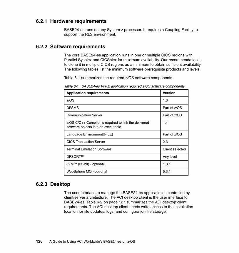
6.2.1 Hardware requirements
BASE24-es runs on any System z processor. It requires a Coupling Facility to support the RLS environment.
6.2.2 Software requirements
The core BASE24-es application runs in one or multiple CICS regions with Parallel Sysplex and CICSplex for maximum availability. Our recommendation is to clone it in multiple CICS regions as a minimum to obtain sufficient availability. The following tables list the minimum software prerequisite products and levels.
Table 6-1 summarizes the required z/OS software components.
Table 6-1 BASE24-es V06.2 application required z/OS software components
6.2.3 Desktop
The user interface to manage the BASE24-es application is controlled by client/server architecture. The ACI desktop client is the user interface to BASE24-es. Table 6-2 on page 127 summarizes the ACI desktop client requirements. The ACI desktop client needs write access to the installation location for file updates, logs, and configuration file storage.
Application requirements Version
z/OS 1.6
DFSMS Part of z/OS
Communication Server Part of z/OS
z/OS C/C++ Compiler is required to link the delivered software objects into an executable
1.4
Language Environment® (LE) Part of z/OS
CICS Transaction Server 2.3
Terminal Emulation Software Client selected
DFSORT™ Any level
JVM™ (32-bit) - optional 1.3.1
WebSphere MQ - optional 5.3.1
126 A Guide to Using ACI Worldwide’s BASE24-es on z/OS
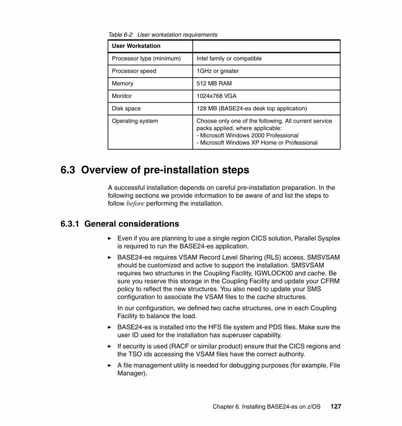
Table 6-2 User workstation requirements
6.3 Overview of pre-installation steps
A successful installation depends on careful pre-installation preparation. In the following sections we provide information to be aware of and list the steps to follow before performing the installation.
6.3.1 General considerations
� Even if you are planning to use a single region CICS solution, Parallel Sysplex is required to run the BASE24-es application.
� BASE24-es requires VSAM Record Level Sharing (RLS) access. SMSVSAM should be customized and active to support the installation. SMSVSAM requires two structures in the Coupling Facility, IGWLOCK00 and cache. Be sure you reserve this storage in the Coupling Facility and update your CFRM policy to reflect the new structures. You also need to update your SMS configuration to associate the VSAM files to the cache structures.
In our configuration, we defined two cache structures, one in each Coupling Facility to balance the load.
� BASE24-es is installed into the HFS file system and PDS files. Make sure the user ID used for the installation has superuser capability.
� If security is used (RACF or similar product) ensure that the CICS regions and the TSO ids accessing the VSAM files have the correct authority.
� A file management utility is needed for debugging purposes (for example, File Manager).
User Workstation
Processor type (minimum) Intel family or compatible
Processor speed 1GHz or greater
Memory 512 MB RAM
Monitor 1024x768 VGA
Disk space 128 MB (BASE24-es desk top application)
Operating system Choose only one of the following. All current service packs applied, where applicable:- Microsoft Windows 2000 Professional- Microsoft Windows XP Home or Professional
Chapter 6. Installing BASE24-es on z/OS 127
� Initially you can install the BASE24-es product on a single CICS region functioning as TOR/AOR (although the ultimate configuration would be at least a TOR on each LPAR routing transactions to cloned AORs that are running on all LPARs). BASE24-es provides its own routing mechanism, but we suggest that you use CP/SM for MRO definitions and operation.
CICS customization requires the use of System Logger. Make sure you have defined the logging environment on the CICS definitions, as well as in the CFRM and LOGR policies. Though CF logging is not required, it is the suggested configuration.
Real Time Analysis and Monitoring CP/SM features are not required.
A TCP/IP socket is required, and it needs to be defined in all TOR regions and in the AOR region that is used by the UI.
� Set up Automatic Restart Manager (ARM), which is a component of z/OS. ARM is a sysplex-wide automatic restart mechanism that does the following:
– Restarts a z/OS subsystem in place, or on a different LPAR if it abends
– Restarts all the elements of a workload (for example, TORs and AORs)
� FTP Server is required for software installation.
� If Electronic Distribution is used, an FTP tool will be needed from a LAN-based personal computer to the host system. Both binary and ASCII data will be transferred. The installation uses the UNIX compress tools TAR and GZIP; you can download them here:
http://www.ibm.com/servers/eserver/zseries/zos/unix/bpxalty1.html
� Provisioning of LAN access to all servers must be completed before installation and IP addresses for servers must be provided.
6.3.2 Installing and implementing the workstation requirements
The onsite installation team's hardware required to install BASE24-es has two options:
� The client provides a minimum of three terminals or personal computer workstations.
� LAN access for the onsite team's mobile (laptop) computers.
Additionally, the installer will require two TSO ids with ISPF access.
6.3.3 Additional requirements
Test devices (ATMs, POS terminals, modems, interchange simulators, interchange connections, and so on) must be available and connected prior to
128 A Guide to Using ACI Worldwide’s BASE24-es on z/OS
BASE24-es installation. In our environment we used a POS device simulator as a device-acquiring endpoint to acquire transactions from POS, and a VISA DPS for acquiring transactions from VISA DPS. Acquirer interfaces are used when the transaction has been forwarded to BASE24-es by a switch or an interchange.
6.3.4 New time library
The SIS_TZ environment variable was introduced with the 64-bit time library (BASE24-es version 03.2 onwards). Because not all operating systems that BASE24-es was running on supported a 64-bit time library at that time, there was a potential for customers to run into issues related to data processing for dates later than the year 2038.
Therefore, a 64-bit time library was introduced into the System Interface Services layer of BASE24-es to circumvent this potential issue. Additionally, an environment variable to accurately represent time zone offsets based on POSIX 1.1 standards was introduced: the SIS_TZ environment variable. Some activities are needed for setting the SIS_TZ environment variable in CICS.
6.4 Installation considerations
We followed the steps described in BASE24-es v06.2 IBM Mainframe Installation Guide to install the product in our test environment. BASE24-es-specific CICS consideration instructions are included as part of the product installation steps, even though the initial CICS setup is not included.
� The BASE24-es Electronic Software Distribution (ESD) contains the object code for BASE24-es, sample “make files” to link edit the objects, files used to load the CICS definitions, and BASE24-es configuration data and JCL to define the BASE24-es data files. The ESD also contains reference publications for BASE24-es.
� A software installation tool utility is provided to help load the BASE24-es files to the Hierarchical File System (HFS) on z/OS and to install the User Interface (UI) for BASE24-es onto a properly configured personal computer. The UNIX System Service (USS) facility for z/OS is the target for loading the BASE24-es files, as this method simplifies the installation process on different platforms.
� The host side installation is executed using parameters provided by the tool. Before running the script, perform a careful review.This script will install BASE24-es to z/OS. Note that it is possible to restart the script at any step, or from the beginning if needed. The installation script file will prompt for verification of default naming conventions and other variables for the system. The script also performs all links of System Integration Services (SIS) and Engine Services (ES). Examine the logs and error files for the link.
Chapter 6. Installing BASE24-es on z/OS 129
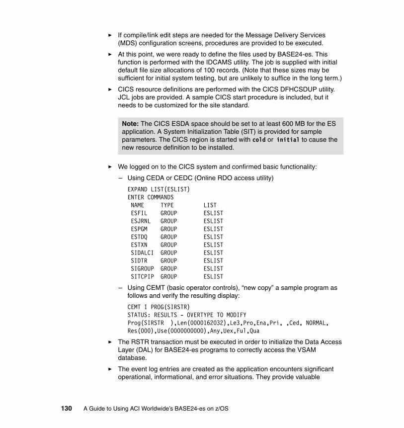
� If compile/link edit steps are needed for the Message Delivery Services (MDS) configuration screens, procedures are provided to be executed.
� At this point, we were ready to define the files used by BASE24-es. This function is performed with the IDCAMS utility. The job is supplied with initial default file size allocations of 100 records. (Note that these sizes may be sufficient for initial system testing, but are unlikely to suffice in the long term.)
� CICS resource definitions are performed with the CICS DFHCSDUP utility. JCL jobs are provided. A sample CICS start procedure is included, but it needs to be customized for the site standard.
� We logged on to the CICS system and confirmed basic functionality:
– Using CEDA or CEDC (Online RDO access utility)
EXPAND LIST(ESLIST) ENTER COMMANDS NAME TYPE LIST ESFIL GROUP ESLIST ESJRNL GROUP ESLIST ESPGM GROUP ESLIST ESTDQ GROUP ESLIST ESTXN GROUP ESLIST SIDALCI GROUP ESLIST SIDTR GROUP ESLIST SIGROUP GROUP ESLIST SITCPIP GROUP ESLIST
– Using CEMT (basic operator controls), “new copy” a sample program as follows and verify the resulting display:
CEMT I PROG(SIRSTR)STATUS: RESULTS - OVERTYPE TO MODIFYProg(SIRSTR ),Len(0000162032),Le3,Pro,Ena,Pri, ,Ced, NORMAL,Res(000),Use(0000000000),Any,Uex,Ful,Qua
� The RSTR transaction must be executed in order to initialize the Data Access Layer (DAL) for BASE24-es programs to correctly access the VSAM database.
� The event log entries are created as the application encounters significant operational, informational, and error situations. They provide valuable
Note: The CICS ESDA space should be set to at least 600 MB for the ES application. A System Initialization Table (SIT) is provided for sample parameters. The CICS region is started with cold or initial to cause the new resource definition to be installed.
130 A Guide to Using ACI Worldwide’s BASE24-es on z/OS
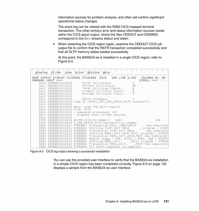
information sources for problem analysis, and often will confirm significant operational status changes.
The event log can be viewed with the R300 CICS mapped terminal transaction. The other primary error and status information sources reside within the CICS spool output, where the files CEEOUT and CEEMSG correspond to the C++ streams stdout and stderr.
� When restarting the CICS region again, examine the CEEOUT CICS job output file to confirm that the RSTR transaction completed successfully and that all OLTP memory tables loaded successfully.
At this point, the BASE24-es is installed in a single CICS region; refer to Figure 6-2.
Figure 6-2 CICS log output showing a successful installation
You can use the provided user interface to verify that the BASE24-es installation in a simple CICA region has been completed correctly. Figure 6-3 on page 132 displays a sample from the BASE24-es user interface.
Chapter 6. Installing BASE24-es on z/OS 131
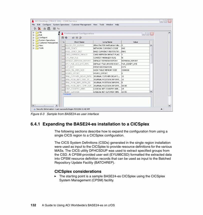
Figure 6-3 Sample from BASE24-es user interface
6.4.1 Expanding the BASE24-es installation to a CICSplex
The following sections describe how to expand the configuration from using a single CICS region to a CICSplex configuration.
The CICS System Definitions (CSDs) generated in the single region installation were used as input to the CICSplex to provide resource definitions for the various MASs. The CICS utility DFHCSDUP was used to extract specified groups from the CSD. A CPSM-provided user exit (EYU9BCSD) formatted the extracted data into CPSM resource definition records that can be used as input to the Batched Repository Update Facility (BATCHREP).
CICSplex considerations� The starting point is a sample BASE24-es CICSplex using the CICSplex
System Management (CPSM) facility.
132 A Guide to Using ACI Worldwide’s BASE24-es on z/OS
� CICS resources definitions are extracted from the single region CSD and are prepared to be input into CPSM using the Batched Repository Update Facility (BATCHREP).
� Sample resource definitions are reviewed and will be provided for establishing the basic BASE24-es CICSplex under the CICSplex Business Application Services (BAS) component of CPSM that is responsible for managing CICS resource definitions and the initialization process in the CICSplex.
� The resource definitions are then loaded into the CICSplex using the BATCHREP facilities.
6.5 Setting up integration with the back-end system
Our system was integrated with a CICS-based simulator that acted as a back-end host authorization system. The list of implementation tasks is as follows:
1. Determine the message format supported by the back-end system.
BASE24-es offers both network message and Host ISO message support.
2. Determine the host type.
BASE24-es can communicate with either an external host (different platform) or an internal host (same platform) application.
3. Determine the communications protocol.
– BASE24-es can connect to external host system using TCP/IP services.
– BASE24-es offers both synchronous and asynchronous connections to an internal host system.
4. Determine whether network management is supported.
Network management supports logon, logoff, key exchange, and echo type messages.
5. Determine the host configuration. In our case:
– We selected the Host ISO 93 message format for this project.
– We simulated an internal host system.
Note: ACI provides procedures to accomplish these tasks. For further details on the CICSplex setup, refer to DTR BASE24-es IBM CICSplex Installation Guide.
Chapter 6. Installing BASE24-es on z/OS 133
– We used synchronous communications to the internal host utilizing the CICS LINK API for this project.
• The host simulators were running in separate host-only regions.
• Remote CICS LINK commands were issued to access the host simulators from the routing regions running BASE24-es.
– Network management was disabled for this test, due to limitations of the host simulator.
Configuring the hostFor this project, we configured our host as follows:
1. Using the BASE24-es User Interface Host Interface Configuration windows, we added three stations to the Host Interface.
Each station represents a copy of the host simulator running in a separate CICS region.
Example: Station name was Host_Station_01.
2. You need to supply a BASE24-es Dynamic Destination Map file (DDMF) entry for each host station configured to BASE24-es.
The service name is the key to this file. It must be unique, and will be used within BASE24-es as a reference point to a component.
Example: Service name was Host_Station_01. In the BASE24-es user interface, select the Stations tab from the Host Interface Configuration window.
3. You need to supply a BASE24-es Synchronous Destination Map file (SYDMF) entry for each host station configured to BASE24-es.
Example: Host station Host_Station_01 was configured to run host program SIMLTR01.
4. CICSplex System Manager (CPSM) was used to configure the host simulator programs for remote execution.
To allow for remote execution, we created three copies of the simulator program: SIMLTR01, SIMLTR02, and SIMLTR03. They needed to be defined with the remote attributes for system and name on the program definition for each simulator program.
Note: A program-in-group definition is also needed for each simulator program.
134 A Guide to Using ACI Worldwide’s BASE24-es on z/OS
5. The BASE24-es User Interface was used to configure the Host Communication Type on the ISO Host tab on the Network Host window so messages are synchronous.
6. The BASE24-es User Interface Routing Configuration Destinations window was used to configure the primary, alternate 1 and alternate 2 destinations in order to utilize all three configured host stations.
Chapter 6. Installing BASE24-es on z/OS 135

136 A Guide to Using ACI Worldwide’s BASE24-es on z/OS

Chapter 7. Setting up and running the initial workload
In this chapter we describe the tasks we performed to set up and run the workload for our projects. We cover the following topics:
� Setting up the workload
� Our ITSO system layout
� Verifying that the installation is operational
� Setting up monitoring
7
© Copyright IBM Corp. 2006. All rights reserved. 137
7.1 Setting up the workload
In order to configure BASE24-es to run the workload, we had to configure the following elements:
� The platform-dependent infrastructure, which is specific to the CICS implementation
� The platform-independent business components, which are common to all implementations
7.1.1 Configuring the BASE24-es infrastructure
We performed these tasks to configure the BASE24-es infrastructure:
� Configure the TCP/IP communication subsystem and define the end-points managed by that subsystem in the System Interface Service (SIS) Message Delivery Service routine files.
� Configure the BASE24-es Integrated Server in the SIS Message Delivery Service routing files.
� Configure the simulators routed to in the same test scenarios as a CICS-based back-end authorization system.
� Configure the SIS Workload Management subsystem.
In the following sections, we describe these tasks in more detail.
TCP/IP configuration1. We needed to determine whether the BASE24-es TCP/IP process would be
acting as a client or a server.
2. We needed to reserve the TPC/IP address and the port number.
3. The BASE24-es TCP/IP Control File (TCPIPCFG) screens allowed us to set these parameters for all processes:
– Service Name is the key to this file. It must be unique, and will be used within BASE24-es as a reference point to a component.
Example: Service name Switch_Station_01. In the BASE24-es user interface, you would select the Stations tab from the Switch Interface Configuration window. The Service name is then entered as one of the stations to be used to send and receive message traffic from a Switch.
– Port number that this BASE24-es TCP/IP process will communicate on.
138 A Guide to Using ACI Worldwide’s BASE24-es on z/OS
– The Destination is a BASE24-es component that will be used as either the acquirer or issuer. These values are bound into the BASE24-es Integrated Server.
– Maximum number of sockets that this BASE24-es TCP/IP task will support.
– TCP/IP Header Type used by the BASE24-es TCP/IP process. Configuration allows for two-byte and four-byte headers.
In our project, we used two-byte headers.
– TCP/IP server type that this BASE24-es TCP/IP will act like. Configuration allows for client and server processes.
In our project, we used both types of processes.
� The BASE24-es Static Destination Map (SDMF) requires a corresponding entry for each TCP/IP Control File service defined.
– Service Name is also the key to this file, and must match one defined in the TCP/IP Control File.
– Transaction ID is the CICS transaction that this BASE24-es TCP/IP process will use during execution.
– The Destination Type will need to be in sync with the type of BASE24-es TCP/IP process that is configured in the TCP/IP Control File.
• For TCP/IP client and server processes, the Destination Type will indicate TCP/IP sockets are being used.
� The BASE24-es Dynamic Destination Map (DDMF) requires a corresponding entry for each TCP/IP Control File (TCPIPCFG) destination defined.
– The TCPIPCFG destination is entered into the DDMF Service Name, which is also the key to the DDMF file.
– Transaction ID is the CICS transaction that this BASE24-es TCP/IP process will use during execution. This is also the name of a CICS Transient Data Queue that a TCP/IP client and server process will access.
– The Destination Type will need to be in sync with the type of BASE24-es TCP/IP process that is configured in the TCP/IP Control File.
� The BASE24-es SOCKRECS File requires a corresponding entry for each TCP/IP Control File service that is defined as a TCP/IP client process.
– Port number that this BASE24-es TCP/IP process will communicate on.
– TCP/IP Address that this client process will connect to.
– The Destination will need to be in sync with a BASE24-es TCP/IP process that is configured in the TCP/IP Control File.
Chapter 7. Setting up and running the initial workload 139
– Disconnect Type is used to determine when a disconnect should be sent from the TCP/IP client to the TCP/IP server.
In our project, we set configuration to not send disconnects.
– TCP/IP Header Type used by the BASE24-es TCP/IP process. Configuration allows for two-byte and four-byte headers.
In our project, we used two-byte headers.
Integrated Server (IS) configuration� Each BASE24-es Integrated Server transaction has its own configuration.
In our project, we used a single configuration.
� A BASE24-es Static Destination Map (SDMF) entry is required for each BASE24-es Integrated Server.
– Service Name is the key to this file, and must be unique.
– Transaction ID is the CICS transaction that this BASE24-es Integrated Server process will use during execution.
– The Destination Type used for our project was set so that a CICS START Transaction command will be issued to pass data from a BASE24-es TCP/IP process to this BASE24-es Integrated Server process.
– The Maximum Servers is the number of concurrent BASE24-es Integrated Server processes that will run when a CICS region is started.
– The Dynamic Service Flag allows you set the amount of time the BASE24-es Integrated Server will run, before it automatically stops and restarts itself.
• In our project, we used the BASE24-es Integrated Servers in long running mode.
• They start when a CICS region starts, and run the entire time the region is up without recycling themselves.
� The BASE24-es Dynamic Destination Map (DDMF) requires an entry for each CICS transaction configured to execute as a BASE24-es Integrated Server.
– Service Name is also the key to this file. This should represent the Integrated Server.
– Transaction ID is the CICS transaction that this BASE24-es Integrated Server process will use during execution.
– The Destination Type will need to be in sync with the communications method used by this BASE24-es Integrated Server.
• In our project, we set the configuration to start a CICS transaction. BASE24-es used CICS transaction XDYR for this purpose.
140 A Guide to Using ACI Worldwide’s BASE24-es on z/OS
Host configurationThe BASE24-es Dynamic Destination entry is required for each host station configured to BASE24-es.
� Service Name is the key to this file. It must be unique, and is be used within BASE24-es as a reference point to a component.
Example: Service name Host_Station_01. In the BASE24-es User Interface, you would select the Stations tab from the Host Interface Configuration window. The Service name is then entered as one of the stations to be used to send and receive message traffic from this host.
� Transaction ID is the CICS transaction that a BASE24-es Integrated Server process will issue a CICS START Transaction command for when sending data to the host in asynchronous mode.
� In our project, we used synchronous mode (CICS LINK).
� The BASE24-es User Interface will be used to configure the Host Communication Type on the ISO Host tab on the Network Host window so messages are asynchronous.
Dynamic routing configurationBASE24-es provides a dynamic transaction routing configuration and user exit that, when used in combination with CICSPlex System Manager (CPSM), allows for dynamic routing of financial transactions.
� During the installation process program DTR6002 will be compiled, then linked as EYU9WRAM.
� CICS System Initialization Table parameters are set to use the IBM-supplied dynamic routing program, EYU9XLOP.
� A BASE24-es Dynamic Transaction Routing Control File entry is needed for each CICS Transaction to be dynamically routed.
– Application Key is the key to the file.
In our project, we used the BASE24-es-supplied transaction of XDYR.
This transaction must be defined as dynamic and routable in all target regions.
– Workload name must match what was defined in CICSPlex System Manager during the installation process.
This is the value that is used by BASE24-es routing and target regions to register with CICSPlex System Manager workload when CICS regions are started.
Chapter 7. Setting up and running the initial workload 141
– The API flag indicates whether the CICSPlex System Manager API is being used.
In our project, we used the API.
– The Handshake Flag indicates whether the routing regions will perform handshake operations to all target regions.
– TOR Scope is a list of CICS APPLIDs for the routing regions that will register with the CICSPlex System Manager TOR Workload.
– AOR Scope is a list of CICS APPLIDs for the target regions that will register with the CICSPlex System Manager AOR Workload.
7.1.2 Business configuration
The BASE24-es User Interface can be used to manually add the data necessary for the initial workload.
The BASE24-es installer can build this data ahead of time. By working with the customer beforehand, the installer can build the necessary data in a project environment at ACI before bringing it to a customer site.
7.2 Our ITSO system layout
In this section, we list the components we used to set up our ITSO environment:
Performance dataAcquirers� Visa DPS interface� SPDH POS devices
Issuers� BASE24-es Scripting Component� ISO 93 Host Simulator
Journal files� Ten journal files, each with two alternate indexes.
Merchant� Eight thousand merchants, each supporting four terminals. � Thirty-two thousand terminals
142 A Guide to Using ACI Worldwide’s BASE24-es on z/OS
Prefix� One prefix record was defined.
Routing� Offline authorization using the BASE24-es Scripting component.� Online authorization using the ISO 93 Host Simulator.
Script� Offline authorization used a base script with a series of subscripts to
complete the authorization process, and accessed the Card file and the Usage file in the process.
� Online authorization used a base script with a series of subscripts to complete pre-screening of the transactions before being sent to the issuer for authorization, and accessed the Card file in the process.
Institution� One institution record was defined.
File partitions� Card
� 3.2 million card records defined.� Partition order is card number� Two partitions each with 1.6 million card records.
Usage� Partition order is card number.� Five partitions.� This starts out as an empty file. � Usage records are added at first use and updated after that.
7.3 Setting up monitoring
The following section describes the tasks you need to perform in order to set up monitoring.
Chapter 7. Setting up and running the initial workload 143
7.3.1 Routing region
BASE24-es allows you to see how each routing region is distributing financial transactions across the registered target regions by using the Dynamic transaction routing AOR Status Menu. Follow these steps:
1. Log into the routing region.
2. Access the Dynamic Transaction Routing Record List.
3. Edit the Dynamic Transaction Routing Application record.
4. At the command line, type: STAT. Then press Enter.
This will display the Dynamic Transaction Routing AOR Status Menu.
– Each registered routing region will appear in the column titled REGN.
– The column titled ALIV will have a value of either NO or YES.
• A value of NO indicates this routing region has not registered and will not have transactions routed to it.
• A value of YES indicates this routing region has registered and will have transactions routed to it.
– The column titled SUCCESS- is a numeric count of the number of financial requests that this routing region has delivered to this target region.
This works for only a single routing region. If more that one routing region is configured, separate access is required.
7.3.2 Target region
BASE24-es allows you to view the event messages produced by all components by using the Event File Browser. Follow these steps:
1. Access any routing or target region in your configuration.
2. Access the BASE24-es Event File Browser. Your first access will take you to the most recent events based on date and time.
7.4 Installation verification
We performed the tasks described in the following sections to verify that the installation completed successfully and was fully operational.
144 A Guide to Using ACI Worldwide’s BASE24-es on z/OS
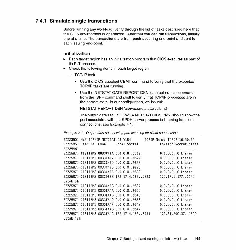
7.4.1 Simulate single transactions
Before running any workload, verify through the list of tasks described here that the CICS environment is operational. After that you can run transactions, initially one at a time. The transactions are from each acquiring end-point and sent to each issuing end-point.
Initialization� Each target region has an initialization program that CICS executes as part of
its PLT process.� Check the following items in each target region:
– TCP/IP task
• Use the CICS supplied CEMT command to verify that the expected TCP/IP tasks are running.
• Use the NETSTAT GATE REPORT DSN 'data set name' command from the ISPF command shell to verify that TCP/IP processes are in the correct state. In our configuration, we issued:
NETSTAT REPORT DSN 'tsorwsa.netstat.cicsibm2’
The output data set ‘TSORWSA.NETSTAT.CICSIBM2’ should show the port associated with the SPDH server process is listening for client connections; see Example 7-1.
Example 7-1 Output data set showing port listening for client connections
EZZ2350I MVS TCP/IP NETSTAT CS V1R4 TCPIP Name: TCPIP 16:30:25EZZ2585I User Id Conn Local Socket Foreign Socket StateEZZ2586I ------- ---- ------------ -------------- -----EZZ2587I CI31IBM2 0033C4EA 0.0.0.0..7708 0.0.0.0..0 ListenEZZ2587I CI31IBM2 0033C4E7 0.0.0.0..9829 0.0.0.0..0 ListenEZZ2587I CI31IBM2 0033C4E9 0.0.0.0..9833 0.0.0.0..0 ListenEZZ2587I CI31IBM2 0033C4E6 0.0.0.0..9826 0.0.0.0..0 ListenEZZ2587I CI31IBM2 0033C4E5 0.0.0.0..9823 0.0.0.0..0 ListenEZZ2587I CI31IBM2 0033D558 172.17.4.153..9823 172.17.1.177..3149 EstablshEZZ2587I CI31IBM2 0033C4E8 0.0.0.0..9827 0.0.0.0..0 ListenEZZ2587I CI31IBM3 0033EA4A 0.0.0.0..9850 0.0.0.0..0 ListenEZZ2587I CI31IBM3 0033EA4B 0.0.0.0..9843 0.0.0.0..0 ListenEZZ2587I CI31IBM3 0033EA49 0.0.0.0..9853 0.0.0.0..0 ListenEZZ2587I CI31IBM3 0033EA47 0.0.0.0..9849 0.0.0.0..0 ListenEZZ2587I CI31IBM3 0033EA48 0.0.0.0..9847 0.0.0.0..0 ListenEZZ2587I CI31IBM3 0033EA4C 172.17.4.153..2934 172.21.200.37..1500 Establish
Chapter 7. Setting up and running the initial workload 145
– AOR status
• Use the BASE24-es Dynamic Transaction Routing AOR Status menu to verify that the target regions have registered.
� Items to be checked in each routing region:
– Use the BASE24-es Event File Browser to verify that all OLTPs were built correctly.
– Use the CEMT command to verify that the configured number of BASE24-es Integrated Server processes are running.
Transaction countsFrom the workload driver, verify that the number of requests and the number of responses match.
Approval codesFrom the workload driver, verify that the responses have the proper approval code.
TimeoutsFrom the workload driver, verify whether any timeouts have been recorded.
7.4.2 Increasing the workload
To increase the workload we needed to increase the size and number of records for a few BASE24-es files, as described here.
CardsThe routing method used for our project requires read access to the Card file for every transaction. To avoid having the Card file become a bottleneck, we performed these tasks:
� We increased the number of records in the file. As a consequence, we needed to increase the VSAM file allocated space by redefining the file.
� This number will vary, depending on the workload goals. To address this, we wrote a program to build these records in a sequential file. Then we used IBM utility programs to load them into the VSAM files.
The card numbers built by this program will need to kept in sync with those delivered by the workload driver.
146 A Guide to Using ACI Worldwide’s BASE24-es on z/OS

� A single Card file can be bottleneck. In our project, we used the BASE24-es File Partitioning feature. This allowed us to create many physical files that appear as one logical file to BASE24-es.
– In our project, we used two partitions to the Card file.
– The BASE24-es User Interface File Partition Configuration window is used to configure the specific fields and values to partition the Card file with.
– The BASE24-es metadata configuration file CONFCSV will need to be updated to incorporate any new Card file assign names that are added during the file partitioning configuration. This is also where the new Card files are connected to a CICS DDNAME.
– VSAM define statements are needed for any new files added.
– CICSPlex System Manager File Definitions and File in Group entries will be needed for any files.
JournalsThe BASE24-es Journal file can be configured with up to seven alternate indexes. One alternate index (AIX®) is required for Online Transaction Processing (OLTP). The other indexes may be optionally configured to provide for online perusal of the Journal file according to various criteria.
� We used the required AIX and one optional AIX, which is a typical configuration.
� Each financial transaction results in a record being written to the BASE24-es Journal File. To avoid having this file become a bottleneck, use more than one journal file.
� BASE24-es allows you to configure many Journal files per institution. This allows you to create many physical files that appear as one logical file.
– Use the BASE24-es User Interface Journal Configuration windows to define the number of journal files necessary to achieve the workload goals.
– BASE24-es uses a hashing algorithm to determine to which of the configured Journal files to write a financial transaction record.
UsageThe routing method used for our project requires a read and update access to the Usage file for every transaction. To avoid having this file become a bottleneck, we performed these tasks:
� We increased the number of records in the file. As a consequence, we needed to increase the VSAM file allocated space by redefining the file.
Chapter 7. Setting up and running the initial workload 147
� A single usage file can be a bottleneck. For our project, we used the BASE24-es File Partitioning feature. This allowed us to create many physical files that appear as one logical file to BASE24-es.
In our project, we used five partitions for the Usage file.
The BASE24-es User Interface File Partition Configuration window is used to configure the specific fields and values to partition the Usage file with.
The BASE24-es metadata configuration file CONFCSV will need to be updated to incorporate any new Usage file assign names that are added during the file partitioning configuration. This is also where the new Card files are connected to a CICS DDNAME.
VSAM define statements are needed for any new files added.
CICSPlex System Manager File Definitions and File in Group entries will be needed for any files.
Merchant processingMerchant processing requires the coordination between merchants and devices.
� In our project, we identified the number of merchants necessary to meet the workload goals and the number of terminals each merchant will support.
� These numbers will vary depending on the workload goals. We addressed this by writing a program to build these records in a sequential file. Then we used IBM utility programs to load them into the VSAM files.
The terminal numbers built by this program will need to kept in sync with those delivered by the workload driver.
148 A Guide to Using ACI Worldwide’s BASE24-es on z/OS
Chapter 8. Tuning BASE24-es on z/OS
In this chapter we discuss considerations you need to be aware of when migrating a BASE24-es installation from a single-transaction-at-a-time development area into a production or performance area, where the financial transactions per seconds goals will be increased. We cover the following topics:
� BASE24-es File Partitioning
� Basic considerations
� Single files as potential bottlenecks
� CICS logging impacts
� RMF Monitor III indicator
8
© Copyright IBM Corp. 2006. All rights reserved. 149

8.1 BASE24-es File Partitioning
The BASE24-es File Partitioning feature allows a data source to appear as a single logical file to the BASE24-es application, while it is really two or more separate physical files. Note these steps:
� BASE24-es User Interface File Partition Configuration window:
– Fields tab
• Select a file to partition.
• Select and order one or more fields from the selected file that will determine the partitioning order.
– Catalog tab
• Enter the range upon which file partitions will be selected. This will be based upon the fields selected on the Fields tab.
• Each range will need to be associated with a unique combination of assign name root and an assign name suffix. This is the tie to a physical file.
� BASE24-es Metadata configuration
– Metadata is maintained through the MataMan application.
– The CONFCSV file contains the necessary information to tie a data source assign to a physical VSAM file using the CICS DDName.
– Each range defined on the Catalog tab will need a corresponding entry in this file.
� CICS resource definitions
– To define the file as a resource to CICS, the CICSPlex System Manager interface is used.
– Each range defined on the Catalog tab will require a file definition entry and a file in Group entry.
8.2 Basic considerations
Here are ways to help you increase overall system performance:
� Place the VSAM index and data components on separate volumes.� Spread the file across multiple volumes. � Use multiple channel paths to access the DASD.� Caching any of these potentially large files is beneficial.
150 A Guide to Using ACI Worldwide’s BASE24-es on z/OS
8.3 Single files as potential bottlenecks
BASE24-es uses VSAM files during the processing of financial transactions. Depending on the configuration, some files can have one or more access per financial transaction. In this section we list files that at one time or another have been identified as bottlenecks (or potential bottlenecks) in a performance environment. We also describe how to remove the bottleneck.
Card file� Access ranges from zero to two reads on every financial transaction,
depending on the authorization method configured.
� BASE24-es concepts
– The BASE24-es File Partitioning ITSO configuration:
• Fields tab
Catalog name is Card
Field partition order number 1
Field name Personal Account Number (PAN)
• Catalog tab
Range one
Low key range value of “9876500000000001”
Assign name root of “CARD_01”
Assign name suffix of “A”
Range two
Low key range value of “9876500001600001”
Assign name root of “CARD_01”
Assign name suffix of “B”
– BASE24-es Metadata configuration CONFCSV file
• Logical Card file
Assign name of “CARD”
Table name of “file_part_catalog”
Physical name of CRDCAT
• Physical Card file 1
Assign name of “CARD_01A”
Table name of “card”
Chapter 8. Tuning BASE24-es on z/OS 151

Physical name of CRD01A
• Physical Card file 2
Assign name of “CARD_01B”
Table name of “card”
Physical name of CRD01B
Journal fileEach financial transaction results in a record being written to the BASE24-es Journal file. To avoid having this file become a bottleneck, use more than one Journal file. Also examine the number of alternate indexes being used.
Each alternate index adds requires additional CPU to process. One way to reduce CPU consumption in a production or performance environment is to remove the alternate indexes that are not required to meet a customer’s business needs. The BASE24-es Journal file comes with seven alternate indexes:
� Account Key� Channel Key� Clerk Key� Clerk Key2� Merchant Key� On-line Key� PAN Key
In our project, we used the On-line Key and the PAN key.
BASE24-es allows you to configure many Journal files per institution, and it is possible to view a group of physical files as a logical entity. In our ITSO environment, we used the BK02 institution for the scenarios.
Use the BASE24-es User Interface Journal Issuer Profile Relationship Configuration windows to define the journal files necessary to achieve the workload goals.
� Primary Journal Profiles:
– JLF_BK02_P00– JLF_BK02_P01– JLF_BK02_P02– JLF_BK02_P03– JLF_BK02_P04– JLF_BK02_P05– JLF_BK02_P06– JLF_BK02_P07
152 A Guide to Using ACI Worldwide’s BASE24-es on z/OS

– JLF_BK02_P08– JLF_BK02_P09
� Alternate Journal Profiles:
– JLF_BK02_A00– JLF_BK02_A01– JLF_BK02_A02– JLF_BK02_A03– JLF_BK02_A04– JLF_BK02_A05– JLF_BK02_A06– JLF_BK02_A07– JLF_BK02_A08– JLF_BK02_A09
Use the BASE24-es User Interface Journal Profile Configuration windows to configure the Journal file assigns. The Journal Profile Assign is associated to an entry in the CONFCSV file. The CONFCSV entry is associated with the CICS DDName, the link to the physical file.
� Primary Journal Profiles:
– JLF_BK02_P00 -
Data Source Assign Name is JLF_BK02_P00_0
CONFCSV
Assign name of “JLF_BK02_P00_0”
Table name of “Journal_key_seq2”
Physical name of P1JR00
– JLF_BK02_P01
Data Source Assign Name is JLF_BK02_P01_1
CONFCSV
Assign name of “JLF_BK02_P01_1”
Table name of “Journal_key_seq2”
Physical name of P1JR01
– All the remaining primary and alternate journal file configurations follow the same pattern.
BASE24-es uses a hashing algorithm to determine to which of the configured Journal files to write a financial transaction record.
Chapter 8. Tuning BASE24-es on z/OS 153
Merchant Delivery Channel fileMerchant processing requires the coordination between merchants and devices.
� Identify the number of merchants your installation have.
� Identify the number of terminals your installation needs to configure.
In our project, we took into account the following performance considerations when we built the merchant processing environment:
� 8,000 merchants, each supporting four terminals, for a total of 32000 terminals.
� A batch program was written to build both merchant and terminal records into separate sequential files. Then IBM utility programs were used to load them into the VSAM files.
Positive Balance fileThis file was not used during the ITSO project.
However, when it is used, then the BASE24-es File Partitioning described for the Card file or the Usage file also applies to the Positive Balance file.
Usage fileAccess is a read and update on every financial transaction, depending on the authorization method configured.
� The BASE24-es File Partitioning ITSO configuration:
– Fields Tab
• Catalog name is Usage• Field partition order number 1• Field name ID
– Catalog Tab
• Range one
Low key range value of “9876500000000000”
Assign name root of “USGD_ID_00”
Assign name suffix of “A”
• Range two
Low key range value of “9876500000400000”
Assign name root of “USGD_ID_01”
154 A Guide to Using ACI Worldwide’s BASE24-es on z/OS

Assign name suffix of “A”
• Range three
Low key range value of “9876500000800000”
Assign name root of “USGD_ID_02”
Assign name suffix of “A”
• Range four
Low key range value of “9876500001200000”
Assign name root of “USGD_ID_03”
Assign name suffix of “A”
• Range five
Low key range value of “9876500001600000”
Assign name root of “USGD_ID_04”
Assign name suffix of “A”
� BASE24-es Metadata configuration CONFCSV file
– Logical Usage file
• Assign name of “USAGE”• Table name of “file_part_catalog”• Physical name of USGCAT
– Physical Usage file 1
• Assign name of “USGD_ID00A”• Table name of “Usage”• Physical name of USGD00
– Physical Usage file 2
• Assign name of “USGD_ID01A”• Table name of “Usage”• Physical name of USGD01
– Physical Usage file 3
• Assign name of “USGD_ID02A”• Table name of “Usage”• Physical name of USGD02
Chapter 8. Tuning BASE24-es on z/OS 155
– Physical Usage file 4
• Assign name of “USGD_ID03A”• Table name of “Usage”• Physical name of USGD04
– Physical Usage file 5
• Assign name of “USGD_ID04A”• Table name of “Usage”• Physical name of USGD04
8.4 CICS logging impacts
CICS allows you to configure the percent full of the CICS log file before the file needs to be trimmed. CICS also allows you to configure what percent the log can be trimmed back to, when the trimming process begins.
When configured correctly, the trimming process has little or no effect on the processing of transactions. When configured incorrectly, however, the trimming process can cause additional overhead. That is, while the trimming process is executing, additional CPU will be used and the customer will experience increased response time. For more information about this topic, refer to the presentation “Logger/CICS - Performance and Common Problems”, which you can find at the following site:
http://www.ibm.com/support/techdocs/atsmastr.nsf/PubAllNum/PRS183
You can also use the DFH0STAT, SMF type88 record, IBM CICS Performance Analyzer tools to investigate common CICS log stream problems.
If your installation is suffering error conditions because the configuration of the parameters AKPFREQ, HIGHOFFLOAD, LOWOFFLOAD and LS_SIZE is not optimized, refer to the following site for helpful information:
http://www.ibm.com/support/docview.wss?uid=swg21052014
8.5 RMF Monitor III indicator
On the RMF Monitor III Coupling Facility Activity report, the Async Change % column can be an indicator that CPU utilization increase and response time increases are possible.
When this value starts to get above 5%, observations have shown an increase in CPU utilization coupled with an increase in response time.
156 A Guide to Using ACI Worldwide’s BASE24-es on z/OS

To address this situation, you might want to investigate further in order to verify that your Coupling Facility configuration is balanced, and possibly redistribute the structure to avoid bottlenecks.
Chapter 8. Tuning BASE24-es on z/OS 157

158 A Guide to Using ACI Worldwide’s BASE24-es on z/OS
Chapter 9. Achieving high availability on z/OS
In this chapter we document our test scenarios. First we describe the objective, the injection, and the expected behavior for each scenario. Then we describe the test we performed against each scenario, and detail the actual behavior. In cases where the expected behavior differs from the actual test behavior, we provide a solution.
The chapter covers the following topics:
� CICS, CP/SM� Data environment� BASE24-es application� Hardware� z/OS and relevant subsystems
9
© Copyright IBM Corp. 2006. All rights reserved. 159
9.1 Test scenarios
High availability is of prime importance to modern online transaction processing (OLTP) systems. Improvements in modern hardware have made fault tolerance of less relative importance—the loss of data in the communications networks far exceeds the loss of information in the OLTP processing system itself, and end-to-end protocols designed to recover from loss of data in the communications networks also assure financial integrity during infrequent hardware failures. However, contractual obligations and end-user requirements continue to make high availability vitally important.
Our test configuration was designed to represent the highest possible level of availability attainable at a single production site. All components were replicated to eliminate any single point of failure. Scenarios were developed to assure that the OLTP processing system remained available through a wide cross-section of potential hardware and software failures.
Note: For simplicity, some of the failover scenarios are illustrated by graphics which show only two LPARs. However, in our configuration we used three LPARs.
9.2 CICS and CP/SM
Here we describe the following CICS and CICSplex scenarios:
1. CMAS failure after workload has been activated2. TCP/IP client - TOR failure3. TCP/IP server - TOR failure4. AOR failure5. TCP/IP server - TOR maintenance6. AOR maintenance7. Dynamically adding a TOR 8. Dynamically adding an AOR
In the following sections we explain these scenarios in detail.
9.2.1 CMAS failure after workload has been activated
Objective and InjectionThe objective of this test case was to verify that the workload keeps running even when a CMAS region fails. To simulate this scenario, we issue the CANCEL CMASname command from SDSF or the console.
160 A Guide to Using ACI Worldwide’s BASE24-es on z/OS
Expected behaviorWith the CMAS running on the same LPAR there would be no adverse effect on either the current workload, or outgoing workload, due to the fact that ACI's EYU9WRAM in the Routing Region (TOR) uses round robin processing to select target regions.
Also, this is possible since there are no affinities within the BASE24-es application. If there were affinity lifetimes of System or Permanent, the workload would fail.
With the CMAS running on a different LPAR and the Routing Region (TOR) routing to Target Regions (AOR) on the other LPAR, those Target Regions will have an additional weight due to the CMAS being unavailable. Workload will still be routed to the AORs, but CPSM will not be able monitor, operate, analyze or otherwise manage these AORs.
Actual behaviorThe workload continued to be processed without interruption.
The LPAR in which the CMAS was failed produced a series of messages in both routing and target regions, as shown here:
10.53.44 STC03506 +EYUNL0902I CICSET01 LMAS LRT CMAS Requested termination initiated 10.53.49 STC03506 +EYUNL0999I CICSET01 LMAS LRT termination complete 10.53.49 STC03506 +EYUXL0011I CICSET01 LMAS shutdown in progress 10.53.49 STC03506 +EYUCL0005I CICSET01 ESSS Receive Link Task terminated 10.53.49 STC03506 +EYUXL0018I CICSET01 LMAS restart in progress... 10.55.14 STC03506 +EYUCL0006I CICSET01 ESSS link to CMASSC30 established 10.55.14 STC03506 +EYUXL0007I CICSET01 LMAS Phase II initialization complete 10.55.14 STC03506 +EYUNL0099I CICSET01 LMAS LRT initialization complete
The other LPARs showed no signs of the failure.
SolutionThe expected behavior was observed.
9.2.2 TCP/IP client - TOR failure
Objective and InjectionThe objective of this test case was to verify that the workload keeps running even when a TOR region running the client fails. To simulate this scenario, we issue the CANCEL TORname command from SDSF or the console.
Chapter 9. Achieving high availability on z/OS 161
Expected behavior1. Responses to messages in flight in the AOR will be reversed when the send
to the TOR fails, and will be reversed.
2. TOR will be restarted by CICS Automatic Restart Manager (ARM).
3. ACI Task Monitor handler will be restarted by first ACI handshake transaction from an available AOR, and will restart IP handler.
4. IP Handler will reconnect to the simulator. Message traffic will resume.
5. If stale messages on outbound TDQ are still accessible, IP handler will read the TDQ and forward messages to the simulator.
6. Messages actually being processed by the IP handler at the time the TOR was cancelled will be lost, as are messages on the outbound TDQ that could not be recovered at region restart. An out-of-balance condition exists where the host has authorized the transaction, but the acquirer has not received the approval.
In the real world we would rely on end-to-end recovery. Though the simulator does not support this functionality, a typical real world interface might generate a reversal on the time-out, then stand in and generate a notification of the stand-in approval.
Actual behaviorAt 100 transactions per seconds (TPS), three routing regions were each processing one-third of the workload. One of the routing regions was cancelled. At this point the workload driver recognized one of its client connections was down, and the workload was reduced by one-third. After the routing region automatically recovered, the client connection was reestablished and the full workload was resumed.
The routing region that was purged was restarted with a new started task number by the Automatic Restart Manager. The routing region was restarted by ARM in less than one second. The routing regions were fully initialized and the client connection was established in 30 seconds, at which time the full workload was resumed. During this period, the workload driver recorded 7 requests as timed out.
Following are the system log messages showing when the cancel command was issued and the ARM start command was issued:
0000000 SC30 2006143 10:32:02.27 ACIRWSA 00000290 C CICSET01,ARMRESTART0000000 SC30 2006143 10:32:02.55 STC04052 00000090 IEF450I CICSET01 CICS - ABEND=S222 U0000 REASON=00000000...
162 A Guide to Using ACI Worldwide’s BASE24-es on z/OS
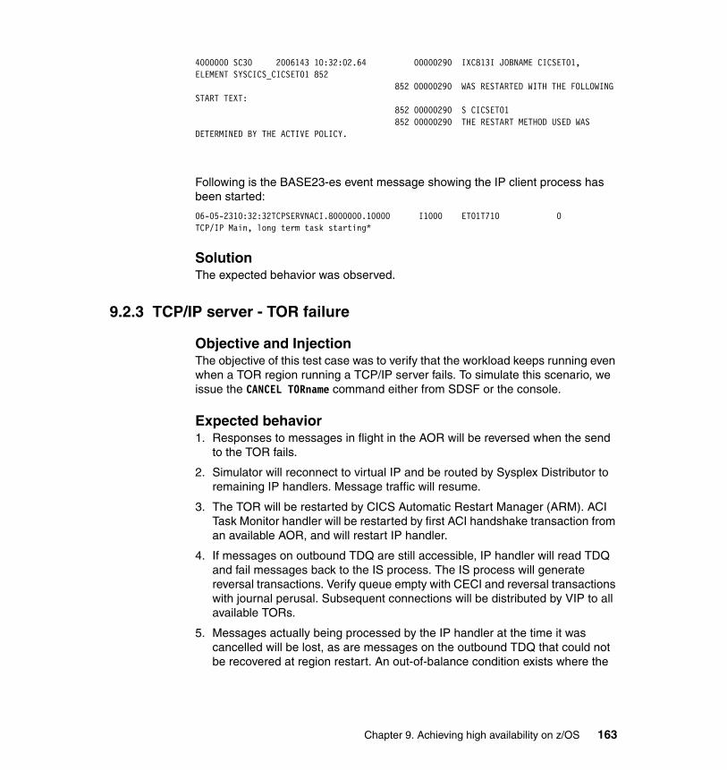
4000000 SC30 2006143 10:32:02.64 00000290 IXC813I JOBNAME CICSET01, ELEMENT SYSCICS_CICSET01 852 852 00000290 WAS RESTARTED WITH THE FOLLOWING START TEXT: 852 00000290 S CICSET01 852 00000290 THE RESTART METHOD USED WAS DETERMINED BY THE ACTIVE POLICY.
Following is the BASE23-es event message showing the IP client process has been started:
06-05-2310:32:32TCPSERVNACI.8000000.10000 I1000 ET01T710 0TCP/IP Main, long term task starting*
SolutionThe expected behavior was observed.
9.2.3 TCP/IP server - TOR failure
Objective and InjectionThe objective of this test case was to verify that the workload keeps running even when a TOR region running a TCP/IP server fails. To simulate this scenario, we issue the CANCEL TORname command either from SDSF or the console.
Expected behavior1. Responses to messages in flight in the AOR will be reversed when the send
to the TOR fails.
2. Simulator will reconnect to virtual IP and be routed by Sysplex Distributor to remaining IP handlers. Message traffic will resume.
3. The TOR will be restarted by CICS Automatic Restart Manager (ARM). ACI Task Monitor handler will be restarted by first ACI handshake transaction from an available AOR, and will restart IP handler.
4. If messages on outbound TDQ are still accessible, IP handler will read TDQ and fail messages back to the IS process. The IS process will generate reversal transactions. Verify queue empty with CECI and reversal transactions with journal perusal. Subsequent connections will be distributed by VIP to all available TORs.
5. Messages actually being processed by the IP handler at the time it was cancelled will be lost, as are messages on the outbound TDQ that could not be recovered at region restart. An out-of-balance condition exists where the
Chapter 9. Achieving high availability on z/OS 163
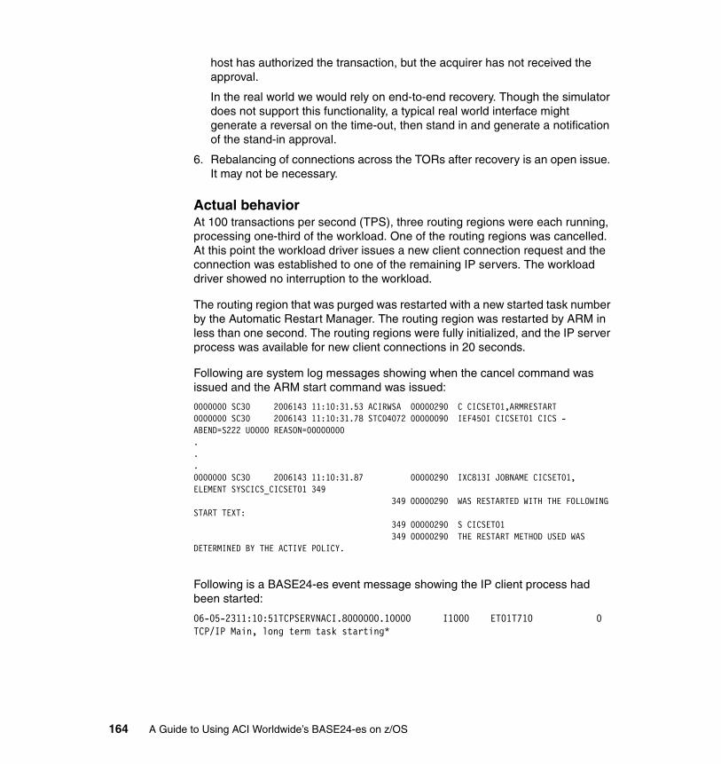
host has authorized the transaction, but the acquirer has not received the approval.
In the real world we would rely on end-to-end recovery. Though the simulator does not support this functionality, a typical real world interface might generate a reversal on the time-out, then stand in and generate a notification of the stand-in approval.
6. Rebalancing of connections across the TORs after recovery is an open issue. It may not be necessary.
Actual behaviorAt 100 transactions per second (TPS), three routing regions were each running, processing one-third of the workload. One of the routing regions was cancelled. At this point the workload driver issues a new client connection request and the connection was established to one of the remaining IP servers. The workload driver showed no interruption to the workload.
The routing region that was purged was restarted with a new started task number by the Automatic Restart Manager. The routing region was restarted by ARM in less than one second. The routing regions were fully initialized, and the IP server process was available for new client connections in 20 seconds.
Following are system log messages showing when the cancel command was issued and the ARM start command was issued:
0000000 SC30 2006143 11:10:31.53 ACIRWSA 00000290 C CICSET01,ARMRESTART0000000 SC30 2006143 11:10:31.78 STC04072 00000090 IEF450I CICSET01 CICS - ABEND=S222 U0000 REASON=00000000...0000000 SC30 2006143 11:10:31.87 00000290 IXC813I JOBNAME CICSET01, ELEMENT SYSCICS_CICSET01 349 349 00000290 WAS RESTARTED WITH THE FOLLOWING START TEXT: 349 00000290 S CICSET01 349 00000290 THE RESTART METHOD USED WAS DETERMINED BY THE ACTIVE POLICY.
Following is a BASE24-es event message showing the IP client process had been started:
06-05-2311:10:51TCPSERVNACI.8000000.10000 I1000 ET01T710 0TCP/IP Main, long term task starting*
164 A Guide to Using ACI Worldwide’s BASE24-es on z/OS
SolutionThe expected behavior was observed. To achieve this behavior, you need to have a restarting mechanism in place for the TOR region. We accomplished that by using ARM.
9.2.4 AOR failure
Objective and InjectionThe objective of this test case was to verify that the workload keeps running even when a AOR region fails. To simulate this scenario, we issue the CANCEL AORname command either from SDSF or the console.
Expected behavior1. The TOR start of XDYR in the failed AOR will fail. The TORs will detect failure,
remove the failed AOR from their active list, and reroute the message to an active AOR.
2. AOR will be restarted by CICS ARM.
3. A handshake program in AOR will register with the active TORs, and traffic will be distributed across all active AORs.
4. Any message actually being processed by the IS processes in the AOR at the time of the failure will be lost. Any associated changes will be backed out of the database. No out-of-balance condition exists since the transaction has been backed out, and the acquirer has not received an approval.
Though the simulator does not support this functionality, a typical real world interface might generate a reversal on the time-out, then stand in and generate a notification of the stand-in approval.
5. Messages on the IS inbound TDQ may or may not be lost.
6. Any messages that cannot be recovered from the IS inbound TDQ will be lost. No out-of-balance condition exists since the transaction has been backed out, and the acquirer has not received an approval.
Though the simulator does not support this functionality, a typical real world interface might generate a reversal on the time-out, then stand in and generate a notification of the stand-in approval.
7. Any messages that can be recovered from the TDQ will be processed. The database will be updated, and responses will be sent to the acquirer. Most of these responses will almost certainly be stale.
Though the simulator does not support this, in the real world the acquirer would generate a late-response reversal to bring things back into balance.
Chapter 9. Achieving high availability on z/OS 165

Actual behaviorThere were nine target regions sharing the workload. One of the target regions was canceled. At this point the BASE24-es user-supplied dynamic routing exit detected that AOR was no longer available, and removed it from the list of available AORs. Workload continued to flow to the remaining AORs. After the AOR is registered with the BASE24-es user-supplied dynamic routing exit, transactions would again be routed to it.
The workload driver detected no interruption in workflow. In this case no messages were lost. The target region that was cancelled was restarted with a new started task number by the Automatic Restart Manager. The target region was restarted by ARM in less than one second. The routing region was fully initialized and registered with the BASE24-es dynamic routing exit in 30 seconds.
Following are the system log messages showing when the cancel command was issued and the ARM start command was issued:
0000000 SC30 2006143 11:37:02.18 ACIRWSA 00000290 C CICSEA03,ARMRESTART0000000 SC30 2006143 11:37:03.21 STC04099 00000090 IEF450I CICSEA03 CICS - ABEND=S222 U0000 REASON=00000000...0000000 SC30 2006143 11:37:03.32 00000290 IXC813I JOBNAME CICSEA03, ELEMENT SYSCICS_CICSEA03 200 200 00000290 WAS RESTARTED WITH THE FOLLOWING START TEXT: 200 00000290 S CICSEA03 200 00000290 THE RESTART METHOD USED WAS DETERMINED BY THE ACTIVE POLICY.
Following is the BASE24-es Dynamic Routing AOR Status Display showing the failed AOR EA03 back in alive status:
REGN ALIV GLOB SUCCESS- ABEND--- ROUTERR-EA01 YES NO 00000581 00000000 00000000EA11 YES NO 00000581 00000000 00000000EA21 YES NO 00000580 00000000 00000000EA02 YES NO 00000580 00000000 00000000EA12 YES NO 00000580 00000000 00000000EA22 YES NO 00000580 00000000 00000000EA03 YES NO 00000467 00000000 00000000EA13 YES NO 00000580 00000000 00000000EA23 YES NO 00000580 00000000 00000000
166 A Guide to Using ACI Worldwide’s BASE24-es on z/OS
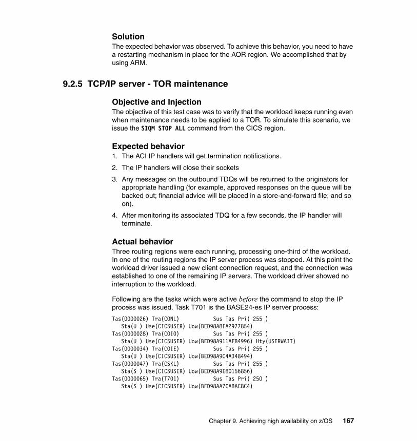
SolutionThe expected behavior was observed. To achieve this behavior, you need to have a restarting mechanism in place for the AOR region. We accomplished that by using ARM.
9.2.5 TCP/IP server - TOR maintenance
Objective and InjectionThe objective of this test case was to verify that the workload keeps running even when maintenance needs to be applied to a TOR. To simulate this scenario, we issue the SIQM STOP ALL command from the CICS region.
Expected behavior1. The ACI IP handlers will get termination notifications.
2. The IP handlers will close their sockets
3. Any messages on the outbound TDQs will be returned to the originators for appropriate handling (for example, approved responses on the queue will be backed out; financial advice will be placed in a store-and-forward file; and so on).
4. After monitoring its associated TDQ for a few seconds, the IP handler will terminate.
Actual behaviorThree routing regions were each running, processing one-third of the workload. In one of the routing regions the IP server process was stopped. At this point the workload driver issued a new client connection request, and the connection was established to one of the remaining IP servers. The workload driver showed no interruption to the workload.
Following are the tasks which were active before the command to stop the IP process was issued. Task T701 is the BASE24-es IP server process:
Tas(0000026) Tra(CONL) Sus Tas Pri( 255 ) Sta(U ) Use(CICSUSER) Uow(BED98A8FA2977854) Tas(0000028) Tra(COI0) Sus Tas Pri( 255 ) Sta(U ) Use(CICSUSER) Uow(BED98A911AFB4996) Hty(USERWAIT)Tas(0000034) Tra(COIE) Sus Tas Pri( 255 ) Sta(U ) Use(CICSUSER) Uow(BED98A9C4A348494) Tas(0000047) Tra(CSKL) Sus Tas Pri( 255 ) Sta(S ) Use(CICSUSER) Uow(BED98A9E80156856) Tas(0000065) Tra(T701) Sus Tas Pri( 250 ) Sta(S ) Use(CICSUSER) Uow(BED98AA7CABAC8C4)
Chapter 9. Achieving high availability on z/OS 167
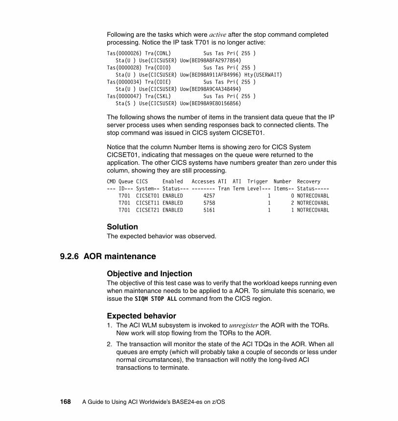
Following are the tasks which were active after the stop command completed processing. Notice the IP task T701 is no longer active:
Tas(0000026) Tra(CONL) Sus Tas Pri( 255 ) Sta(U ) Use(CICSUSER) Uow(BED98A8FA2977854) Tas(0000028) Tra(COI0) Sus Tas Pri( 255 ) Sta(U ) Use(CICSUSER) Uow(BED98A911AFB4996) Hty(USERWAIT)Tas(0000034) Tra(COIE) Sus Tas Pri( 255 ) Sta(U ) Use(CICSUSER) Uow(BED98A9C4A348494) Tas(0000047) Tra(CSKL) Sus Tas Pri( 255 ) Sta(S ) Use(CICSUSER) Uow(BED98A9E80156856)
The following shows the number of items in the transient data queue that the IP server process uses when sending responses back to connected clients. The stop command was issued in CICS system CICSET01.
Notice that the column Number Items is showing zero for CICS System CICSET01, indicating that messages on the queue were returned to the application. The other CICS systems have numbers greater than zero under this column, showing they are still processing.
CMD Queue CICS Enabled Accesses ATI ATI Trigger Number Recovery --- ID--- System-- Status--- -------- Tran Term Level--- Items-- Status----- T701 CICSET01 ENABLED 4257 1 0 NOTRECOVABL T701 CICSET11 ENABLED 5758 1 2 NOTRECOVABL T701 CICSET21 ENABLED 5161 1 1 NOTRECOVABL
SolutionThe expected behavior was observed.
9.2.6 AOR maintenance
Objective and InjectionThe objective of this test case was to verify that the workload keeps running even when maintenance needs to be applied to a AOR. To simulate this scenario, we issue the SIQM STOP ALL command from the CICS region.
Expected behavior1. The ACI WLM subsystem is invoked to unregister the AOR with the TORs.
New work will stop flowing from the TORs to the AOR.
2. The transaction will monitor the state of the ACI TDQs in the AOR. When all queues are empty (which will probably take a couple of seconds or less under normal circumstances), the transaction will notify the long-lived ACI transactions to terminate.
168 A Guide to Using ACI Worldwide’s BASE24-es on z/OS
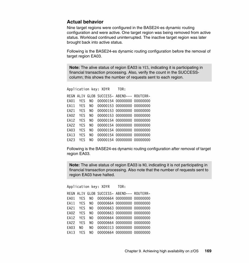
Actual behaviorNine target regions were configured in the BASE24-es dynamic routing configuration and were active. One target region was being removed from active status. Workload continued uninterrupted. The inactive target region was later brought back into active status.
Following is the BASE24-es dynamic routing configuration before the removal of target region EA03.
Application key: XDYR TOR:
REGN ALIV GLOB SUCCESS- ABEND--- ROUTERR-EA01 YES NO 00000154 00000000 00000000EA11 YES NO 00000153 00000000 00000000EA21 YES NO 00000153 00000000 00000000EA02 YES NO 00000153 00000000 00000000EA12 YES NO 00000154 00000000 00000000EA22 YES NO 00000154 00000000 00000000EA03 YES NO 00000154 00000000 00000000EA13 YES NO 00000154 00000000 00000000EA23 YES NO 00000154 00000000 00000000
Following is the BASE24-es dynamic routing configuration after removal of target region EA03.
Application key: XDYR TOR:
REGN ALIV GLOB SUCCESS- ABEND--- ROUTERR- EA01 YES NO 00000664 00000000 00000000 EA11 YES NO 00000664 00000000 00000000 EA21 YES NO 00000663 00000000 00000000 EA02 YES NO 00000663 00000000 00000000 EA12 YES NO 00000664 00000000 00000000 EA22 YES NO 00000664 00000000 00000000 EA03 NO NO 00000313 00000000 00000000 EA13 YES NO 00000664 00000000 00000000
Note: The alive status of region EA03 is YES, indicating it is participating in financial transaction processing. Also, verify the count in the SUCCESS- column; this shows the number of requests sent to each region.
Note: The alive status of region EA03 is NO, indicating it is not participating in financial transaction processing. Also note that the number of requests sent to region EA03 have halted.
Chapter 9. Achieving high availability on z/OS 169
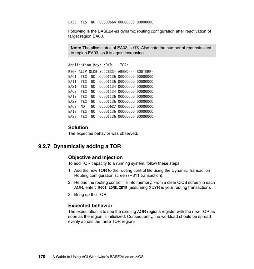
EA23 YES NO 00000664 00000000 00000000
Following is the BASE24-es dynamic routing configuration after reactivation of target region EA03.
Application key: XDYR TOR:
REGN ALIV GLOB SUCCESS- ABEND--- ROUTERR- EA01 YES NO 00001135 00000000 00000000 EA11 YES NO 00001135 00000000 00000000 EA21 YES NO 00001134 00000000 00000000 EA02 YES NO 00001134 00000000 00000000 EA12 YES NO 00001135 00000000 00000000 EA22 YES NO 00001135 00000000 00000000 EA03 NO NO 00000627 00000000 00000000 EA13 YES NO 00001135 00000000 00000000 EA23 YES NO 00001135 00000000 00000000
SolutionThe expected behavior was observed.
9.2.7 Dynamically adding a TOR
Objective and InjectionTo add TOR capacity to a running system, follow these steps:
1. Add the new TOR to the routing control file using the Dynamic Transaction Routing configuration screen (R311 transaction).
2. Reload the routing control file into memory. From a clear CICS screen in each AOR, enter: R001 LONE,XDYR (assuming XDYR is your routing transaction).
3. Bring up the TOR.
Expected behaviorThe expectation is to see the existing AOR regions register with the new TOR as soon as the region is initialized. Consequently, the workload should be spread evenly across the three TOR regions.
Note: The alive status of EA03 is YES. Also note the number of requests sent to region EA03, as it is again increasing.
170 A Guide to Using ACI Worldwide’s BASE24-es on z/OS
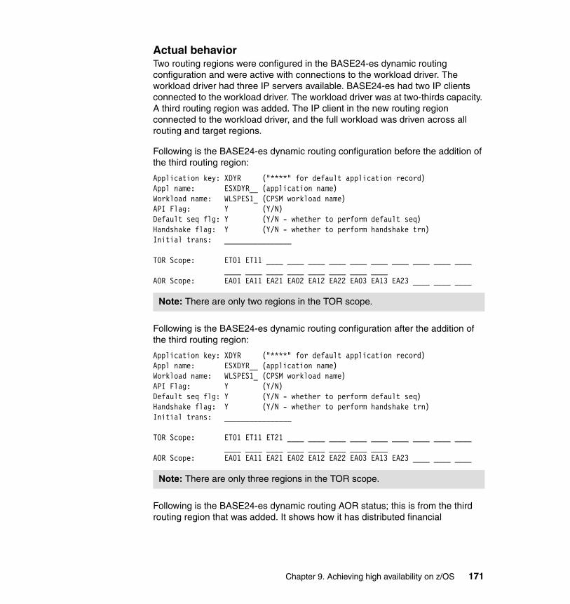
Actual behaviorTwo routing regions were configured in the BASE24-es dynamic routing configuration and were active with connections to the workload driver. The workload driver had three IP servers available. BASE24-es had two IP clients connected to the workload driver. The workload driver was at two-thirds capacity. A third routing region was added. The IP client in the new routing region connected to the workload driver, and the full workload was driven across all routing and target regions.
Following is the BASE24-es dynamic routing configuration before the addition of the third routing region:
Application key: XDYR ("****" for default application record) Appl name: ESXDYR__ (application name) Workload name: WLSPES1_ (CPSM workload name) API Flag: Y (Y/N) Default seq flg: Y (Y/N - whether to perform default seq) Handshake flag: Y (Y/N - whether to perform handshake trn) Initial trans: ________________ TOR Scope: ET01 ET11 ____ ____ ____ ____ ____ ____ ____ ____ ____ ____ ____ ____ ____ ____ ____ ____ ____ ____ AOR Scope: EA01 EA11 EA21 EA02 EA12 EA22 EA03 EA13 EA23 ____ ____ ____
Following is the BASE24-es dynamic routing configuration after the addition of the third routing region:
Application key: XDYR ("****" for default application record) Appl name: ESXDYR__ (application name) Workload name: WLSPES1_ (CPSM workload name) API Flag: Y (Y/N) Default seq flg: Y (Y/N - whether to perform default seq) Handshake flag: Y (Y/N - whether to perform handshake trn) Initial trans: ________________ TOR Scope: ET01 ET11 ET21 ____ ____ ____ ____ ____ ____ ____ ____ ____ ____ ____ ____ ____ ____ ____ ____ ____ AOR Scope: EA01 EA11 EA21 EA02 EA12 EA22 EA03 EA13 EA23 ____ ____ ____
Following is the BASE24-es dynamic routing AOR status; this is from the third routing region that was added. It shows how it has distributed financial
Note: There are only two regions in the TOR scope.
Note: There are only three regions in the TOR scope.
Chapter 9. Achieving high availability on z/OS 171
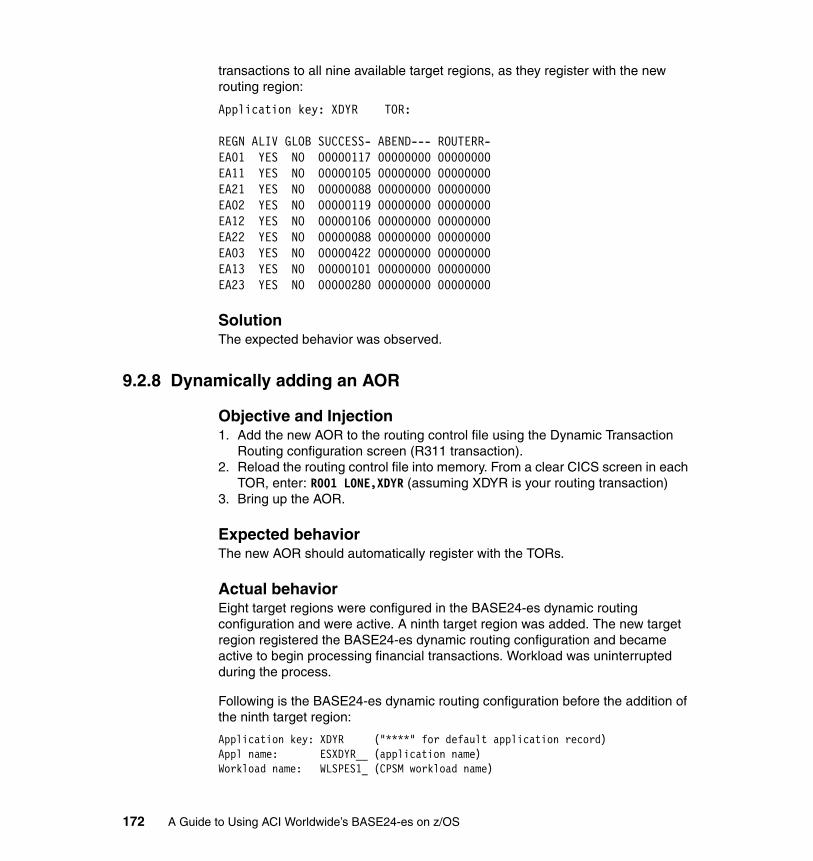
transactions to all nine available target regions, as they register with the new routing region:
Application key: XDYR TOR: REGN ALIV GLOB SUCCESS- ABEND--- ROUTERR-EA01 YES NO 00000117 00000000 00000000EA11 YES NO 00000105 00000000 00000000EA21 YES NO 00000088 00000000 00000000EA02 YES NO 00000119 00000000 00000000EA12 YES NO 00000106 00000000 00000000EA22 YES NO 00000088 00000000 00000000EA03 YES NO 00000422 00000000 00000000EA13 YES NO 00000101 00000000 00000000EA23 YES NO 00000280 00000000 00000000
SolutionThe expected behavior was observed.
9.2.8 Dynamically adding an AOR
Objective and Injection1. Add the new AOR to the routing control file using the Dynamic Transaction
Routing configuration screen (R311 transaction).2. Reload the routing control file into memory. From a clear CICS screen in each
TOR, enter: R001 LONE,XDYR (assuming XDYR is your routing transaction)3. Bring up the AOR.
Expected behaviorThe new AOR should automatically register with the TORs.
Actual behaviorEight target regions were configured in the BASE24-es dynamic routing configuration and were active. A ninth target region was added. The new target region registered the BASE24-es dynamic routing configuration and became active to begin processing financial transactions. Workload was uninterrupted during the process.
Following is the BASE24-es dynamic routing configuration before the addition of the ninth target region:
Application key: XDYR ("****" for default application record) Appl name: ESXDYR__ (application name) Workload name: WLSPES1_ (CPSM workload name)
172 A Guide to Using ACI Worldwide’s BASE24-es on z/OS

API Flag: Y (Y/N) Default seq flg: Y (Y/N - whether to perform default seq) Handshake flag: Y (Y/N - whether to perform handshake trn) Initial trans: ________________ TOR Scope: ET01 ET11 ET21 ____ ____ ____ ____ ____ ____ ____ ____ ____ ____ ____ ____ ____ ____ ____ ____ ____ AOR Scope: EA01 EA11 EA21 EA02 EA12 EA22 EA03 EA13 ____ ____ ____ ____ ____ ____ ____ ____ ____ ____ ____ ____
Following is the BASE24-es dynamic routing AOR status:
Application key: XDYR TOR: REGN ALIV GLOB SUCCESS- ABEND--- ROUTERR-EA01 YES NO 00000088 00000000 00000000EA11 YES NO 00000088 00000000 00000000EA21 YES NO 00000088 00000000 00000000EA02 YES NO 00000088 00000000 00000000EA12 YES NO 00000088 00000000 00000000EA22 YES NO 00000088 00000000 00000000EA03 YES NO 00000087 00000000 00000000EA13 YES NO 00000087 00000000 00000000
Following is the BASE24-es dynamic routing configuration after the addition of the ninth target region:
Application key: XDYR ("****" for default application record) Appl name: ESXDYR__ (application name) Workload name: WLSPES1_ (CPSM workload name) API Flag: Y (Y/N) Default seq flg: Y (Y/N - whether to perform default seq) Handshake flag: Y (Y/N - whether to perform handshake trn) Initial trans: ________________ TOR Scope: ET01 ET11 ET21 ____ ____ ____ ____ ____ ____ ____ ____ ____ ____ ____ ____ ____ ____ ____ ____ ____ AOR Scope: EA01 EA11 EA21 EA02 EA12 EA22 EA03 EA13 EA23 ____ ____ ____ ____ ____ ____ ____ ____ ____ ____ ____
Note: The AOR scope does not include region EA23.
Note: The AOR column does not include region EA23.
Note: The AOR scope includes region EA23.
Chapter 9. Achieving high availability on z/OS 173

Following is the BASE24-es dynamic routing AOR status:
Application key: XDYR TOR: REGN ALIV GLOB SUCCESS- ABEND--- ROUTERR-EA01 YES NO 00000664 00000000 00000000EA11 YES NO 00000672 00000000 00000000EA21 YES NO 00001084 00000000 00000000EA02 YES NO 00000664 00000000 00000000EA12 YES NO 00000666 00000000 00000000EA22 YES NO 00000933 00000000 00000000EA03 YES NO 00000663 00000000 00000000EA13 YES NO 00000662 00000000 00000000EA23 YES NO 00000080 00000000 00000000
SolutionThe expected behavior was observed.
9.3 Data environment
Here we describe the data environment scenarios:
1. SMSVSAM failure
2. Lock structure full - IGWLOCK00
3. R/O data table at initial time
4. R/O flat file at initial time
In the following sections we explain these scenarios in detail.
9.3.1 SMSVSAM failure
Objective and InjectionThe objective of this scenario was to verify that the workload is still running even when an SMSVSAM failure occurs, and to document if any recovery actions need to be taken. To simulate the failure, we issue the V SMS,SMSVSAM,TERMINATESERVER command.
Note: The AOR column include regions EA23, and transactions are being successfully routed to it.
174 A Guide to Using ACI Worldwide’s BASE24-es on z/OS
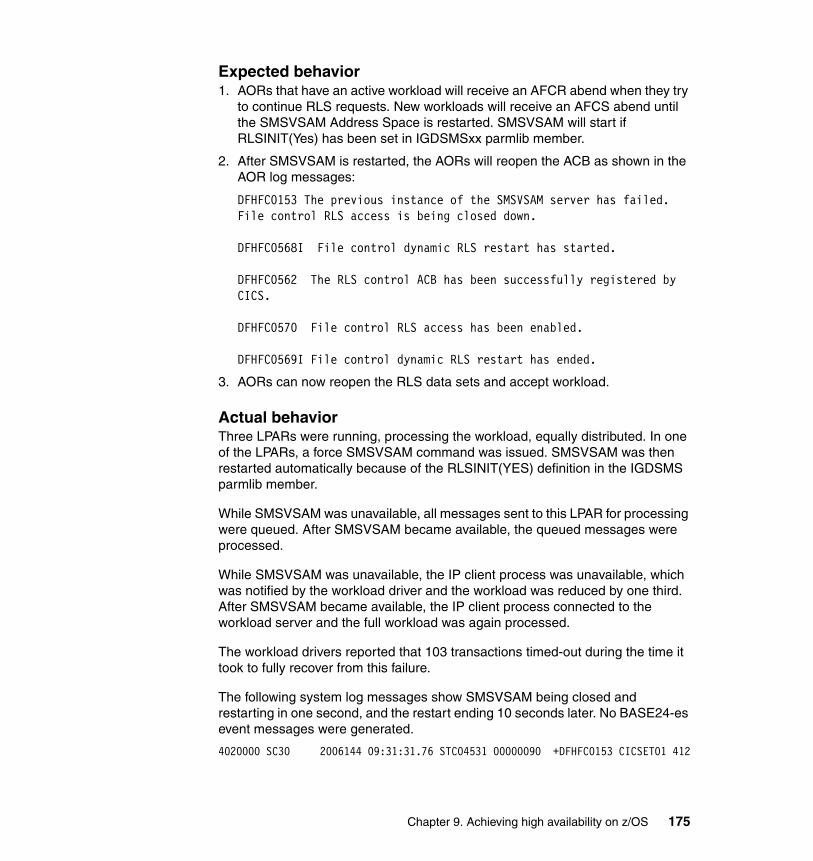
Expected behavior1. AORs that have an active workload will receive an AFCR abend when they try
to continue RLS requests. New workloads will receive an AFCS abend until the SMSVSAM Address Space is restarted. SMSVSAM will start if RLSINIT(Yes) has been set in IGDSMSxx parmlib member.
2. After SMSVSAM is restarted, the AORs will reopen the ACB as shown in the AOR log messages:
DFHFC0153 The previous instance of the SMSVSAM server has failed. File control RLS access is being closed down.
DFHFC0568I File control dynamic RLS restart has started.
DFHFC0562 The RLS control ACB has been successfully registered by CICS.
DFHFC0570 File control RLS access has been enabled.
DFHFC0569I File control dynamic RLS restart has ended.
3. AORs can now reopen the RLS data sets and accept workload.
Actual behaviorThree LPARs were running, processing the workload, equally distributed. In one of the LPARs, a force SMSVSAM command was issued. SMSVSAM was then restarted automatically because of the RLSINIT(YES) definition in the IGDSMS parmlib member.
While SMSVSAM was unavailable, all messages sent to this LPAR for processing were queued. After SMSVSAM became available, the queued messages were processed.
While SMSVSAM was unavailable, the IP client process was unavailable, which was notified by the workload driver and the workload was reduced by one third. After SMSVSAM became available, the IP client process connected to the workload server and the full workload was again processed.
The workload drivers reported that 103 transactions timed-out during the time it took to fully recover from this failure.
The following system log messages show SMSVSAM being closed and restarting in one second, and the restart ending 10 seconds later. No BASE24-es event messages were generated.
4020000 SC30 2006144 09:31:31.76 STC04531 00000090 +DFHFC0153 CICSET01 412
Chapter 9. Achieving high availability on z/OS 175
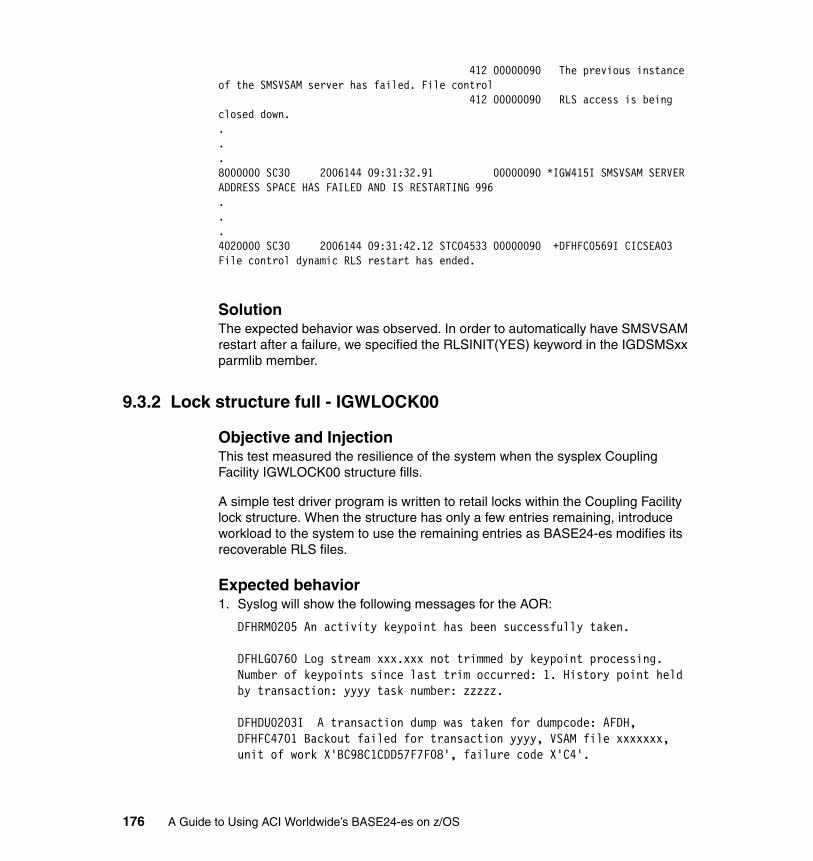
412 00000090 The previous instance of the SMSVSAM server has failed. File control 412 00000090 RLS access is being closed down....8000000 SC30 2006144 09:31:32.91 00000090 *IGW415I SMSVSAM SERVER ADDRESS SPACE HAS FAILED AND IS RESTARTING 996...4020000 SC30 2006144 09:31:42.12 STC04533 00000090 +DFHFC0569I CICSEA03 File control dynamic RLS restart has ended.
SolutionThe expected behavior was observed. In order to automatically have SMSVSAM restart after a failure, we specified the RLSINIT(YES) keyword in the IGDSMSxx parmlib member.
9.3.2 Lock structure full - IGWLOCK00
Objective and InjectionThis test measured the resilience of the system when the sysplex Coupling Facility IGWLOCK00 structure fills.
A simple test driver program is written to retail locks within the Coupling Facility lock structure. When the structure has only a few entries remaining, introduce workload to the system to use the remaining entries as BASE24-es modifies its recoverable RLS files.
Expected behavior1. Syslog will show the following messages for the AOR:
DFHRM0205 An activity keypoint has been successfully taken.
DFHLG0760 Log stream xxx.xxx not trimmed by keypoint processing. Number of keypoints since last trim occurred: 1. History point held by transaction: yyyy task number: zzzzz.
DFHDU0203I A transaction dump was taken for dumpcode: AFDH, DFHFC4701 Backout failed for transaction yyyy, VSAM file xxxxxxx, unit of work X'BC98C1CDD57F7F08', failure code X'C4'.
176 A Guide to Using ACI Worldwide’s BASE24-es on z/OS
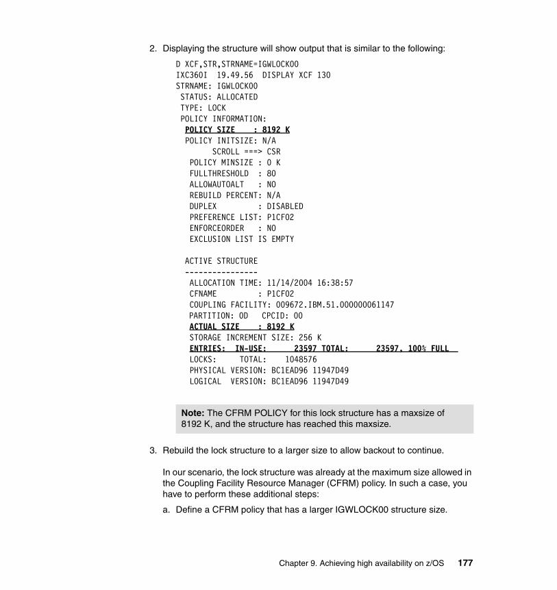
2. Displaying the structure will show output that is similar to the following:
D XCF,STR,STRNAME=IGWLOCK00IXC360I 19.49.56 DISPLAY XCF 130STRNAME: IGWLOCK00 STATUS: ALLOCATED TYPE: LOCK POLICY INFORMATION: POLICY SIZE : 8192 K POLICY INITSIZE: N/A SCROLL ===> CSR POLICY MINSIZE : 0 K FULLTHRESHOLD : 80 ALLOWAUTOALT : NO REBUILD PERCENT: N/A DUPLEX : DISABLED PREFERENCE LIST: P1CF02 ENFORCEORDER : NO EXCLUSION LIST IS EMPTY ACTIVE STRUCTURE ---------------- ALLOCATION TIME: 11/14/2004 16:38:57 CFNAME : P1CF02 COUPLING FACILITY: 009672.IBM.51.000000061147
PARTITION: 0D CPCID: 00 ACTUAL SIZE : 8192 K STORAGE INCREMENT SIZE: 256 K ENTRIES: IN-USE: 23597 TOTAL: 23597, 100% FULL LOCKS: TOTAL: 1048576 PHYSICAL VERSION: BC1EAD96 11947D49 LOGICAL VERSION: BC1EAD96 11947D49
3. Rebuild the lock structure to a larger size to allow backout to continue.
In our scenario, the lock structure was already at the maximum size allowed in the Coupling Facility Resource Manager (CFRM) policy. In such a case, you have to perform these additional steps:
a. Define a CFRM policy that has a larger IGWLOCK00 structure size.
Note: The CFRM POLICY for this lock structure has a maxsize of 8192 K, and the structure has reached this maxsize.
Chapter 9. Achieving high availability on z/OS 177
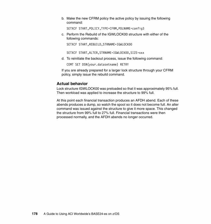
b. Make the new CFRM policy the active policy by issuing the following command:
SETXCF START,POLICY,TYPE=CFRM,POLNAME=config3
c. Perform the Rebuild of the IGWLOCK00 structure with either of the following commands:
SETXCF START,REBUILD,STRNAME=IGWLOCK00
SETXCF START,ALTER,STRNAME=IGWLOCK00,SIZE=xxx
d. To reinitiate the backout process, issue the following command:
CEMT SET DSN(your.datasetname) RETRY
If you are already prepared for a larger lock structure through your CFRM policy, simply issue the rebuild command.
Actual behaviorLock structure IGWLOCK00 was preloaded so that it was approximately 95% full. Then workload was applied to increase the structure to 99% full.
At this point each financial transaction produces an AFDH abend. Each of these abends produces a dump, so watch the spool so it does not become full. An alter command was issued against the structure to give it more space. This changed the structure from 99% full to 27% full. Financial transactions were then processed normally, and the AFDH abends no longer occurred.
178 A Guide to Using ACI Worldwide’s BASE24-es on z/OS
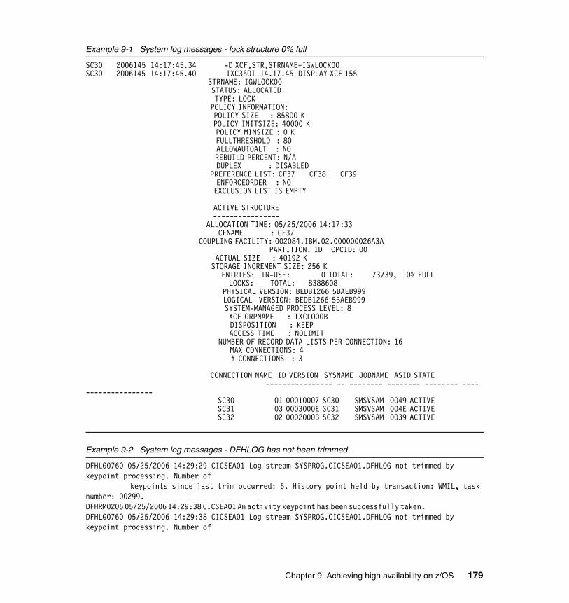
Example 9-1 System log messages - lock structure 0% full
SC30 2006145 14:17:45.34 -D XCF,STR,STRNAME=IGWLOCK00 SC30 2006145 14:17:45.40 IXC360I 14.17.45 DISPLAY XCF 155 STRNAME: IGWLOCK00 STATUS: ALLOCATED TYPE: LOCK POLICY INFORMATION: POLICY SIZE : 85800 K POLICY INITSIZE: 40000 K POLICY MINSIZE : 0 K FULLTHRESHOLD : 80 ALLOWAUTOALT : NO REBUILD PERCENT: N/A DUPLEX : DISABLED PREFERENCE LIST: CF37 CF38 CF39 ENFORCEORDER : NO EXCLUSION LIST IS EMPTY ACTIVE STRUCTURE ---------------- ALLOCATION TIME: 05/25/2006 14:17:33 CFNAME : CF37 COUPLING FACILITY: 002084.IBM.02.000000026A3A PARTITION: 1D CPCID: 00 ACTUAL SIZE : 40192 K STORAGE INCREMENT SIZE: 256 K ENTRIES: IN-USE: 0 TOTAL: 73739, 0% FULL LOCKS: TOTAL: 8388608 PHYSICAL VERSION: BEDB1266 5BAEB999 LOGICAL VERSION: BEDB1266 5BAEB999 SYSTEM-MANAGED PROCESS LEVEL: 8 XCF GRPNAME : IXCLO00B DISPOSITION : KEEP ACCESS TIME : NOLIMIT NUMBER OF RECORD DATA LISTS PER CONNECTION: 16 MAX CONNECTIONS: 4 # CONNECTIONS : 3 CONNECTION NAME ID VERSION SYSNAME JOBNAME ASID STATE ---------------- -- -------- -------- -------- ---- ---------------- SC30 01 00010007 SC30 SMSVSAM 0049 ACTIVE SC31 03 0003000E SC31 SMSVSAM 004E ACTIVE SC32 02 0002000B SC32 SMSVSAM 0039 ACTIVE
Example 9-2 System log messages - DFHLOG has not been trimmed
DFHLG0760 05/25/2006 14:29:29 CICSEA01 Log stream SYSPROG.CICSEA01.DFHLOG not trimmed by keypoint processing. Number of keypoints since last trim occurred: 6. History point held by transaction: WMIL, task number: 00299. DFHRM0205 05/25/2006 14:29:38 CICSEA01 An activity keypoint has been successfully taken. DFHLG0760 05/25/2006 14:29:38 CICSEA01 Log stream SYSPROG.CICSEA01.DFHLOG not trimmed by keypoint processing. Number of
Chapter 9. Achieving high availability on z/OS 179
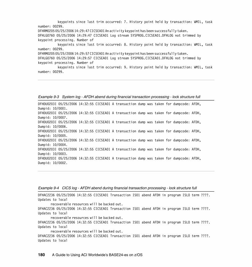
keypoints since last trim occurred: 7. History point held by transaction: WMIL, task number: 00299. DFHRM0205 05/25/2006 14:29:47 CICSEA01 An activity keypoint has been successfully taken. DFHLG0760 05/25/2006 14:29:47 CICSEA01 Log stream SYSPROG.CICSEA01.DFHLOG not trimmed by keypoint processing. Number of keypoints since last trim occurred: 8. History point held by transaction: WMIL, task number: 00299. DFHRM0205 05/25/2006 14:29:57 CICSEA01 An activity keypoint has been successfully taken. DFHLG0760 05/25/2006 14:29:57 CICSEA01 Log stream SYSPROG.CICSEA01.DFHLOG not trimmed by keypoint processing. Number of keypoints since last trim occurred: 9. History point held by transaction: WMIL, task number: 00299.
Example 9-3 System log - AFDH abend during financial transaction processing - lock structure full
DFHDU0203I 05/25/2006 14:32:55 CICSEA01 A transaction dump was taken for dumpcode: AFDH, Dumpid: 10/0001. DFHDU0203I 05/25/2006 14:32:55 CICSEA01 A transaction dump was taken for dumpcode: AFDH, Dumpid: 10/0007. DFHDU0203I 05/25/2006 14:32:55 CICSEA01 A transaction dump was taken for dumpcode: AFDH, Dumpid: 10/0006. DFHDU0203I 05/25/2006 14:32:55 CICSEA01 A transaction dump was taken for dumpcode: AFDH, Dumpid: 10/0005. DFHDU0203I 05/25/2006 14:32:55 CICSEA01 A transaction dump was taken for dumpcode: AFDH, Dumpid: 10/0004. DFHDU0203I 05/25/2006 14:32:55 CICSEA01 A transaction dump was taken for dumpcode: AFDH, Dumpid: 10/0003. DFHDU0203I 05/25/2006 14:32:55 CICSEA01 A transaction dump was taken for dumpcode: AFDH, Dumpid: 10/0002.
Example 9-4 CICS log - AFDH abend during financial transaction processing - lock structure full
DFHAC2236 05/25/2006 14:32:55 CICSEA01 Transaction IS01 abend AFDH in program ISLO term ????. Updates to local recoverable resources will be backed out. DFHAC2236 05/25/2006 14:32:55 CICSEA01 Transaction IS01 abend AFDH in program ISLO term ????. Updates to local recoverable resources will be backed out. DFHAC2236 05/25/2006 14:32:55 CICSEA01 Transaction IS01 abend AFDH in program ISLO term ????. Updates to local recoverable resources will be backed out. DFHAC2236 05/25/2006 14:32:55 CICSEA01 Transaction IS01 abend AFDH in program ISLO term ????. Updates to local
180 A Guide to Using ACI Worldwide’s BASE24-es on z/OS
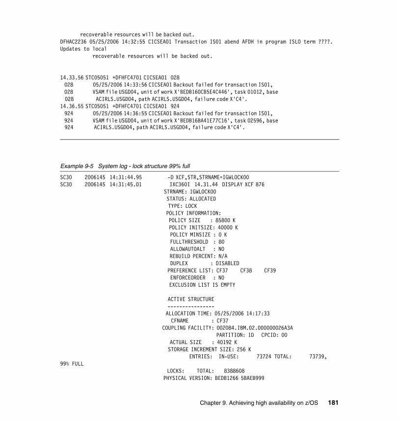
recoverable resources will be backed out. DFHAC2236 05/25/2006 14:32:55 CICSEA01 Transaction IS01 abend AFDH in program ISLO term ????. Updates to local recoverable resources will be backed out. 14.33.56 STC05051 +DFHFC4701 CICSEA01 028 028 05/25/2006 14:33:56 CICSEA01 Backout failed for transaction IS01, 028 VSAM file USGD04, unit of work X'BEDB160CB5E4C446', task 01012, base 028 ACIRLS.USGD04, path ACIRLS.USGD04, failure code X'C4'. 14.36.55 STC05051 +DFHFC4701 CICSEA01 924 924 05/25/2006 14:36:55 CICSEA01 Backout failed for transaction IS01, 924 VSAM file USGD04, unit of work X'BEDB16BA41E77C16', task 02596, base 924 ACIRLS.USGD04, path ACIRLS.USGD04, failure code X'C4'.
Example 9-5 System log - lock structure 99% full
SC30 2006145 14:31:44.95 -D XCF,STR,STRNAME=IGWLOCK00 SC30 2006145 14:31:45.01 IXC360I 14.31.44 DISPLAY XCF 876 STRNAME: IGWLOCK00 STATUS: ALLOCATED TYPE: LOCK POLICY INFORMATION: POLICY SIZE : 85800 K POLICY INITSIZE: 40000 K POLICY MINSIZE : 0 K FULLTHRESHOLD : 80 ALLOWAUTOALT : NO REBUILD PERCENT: N/A DUPLEX : DISABLED PREFERENCE LIST: CF37 CF38 CF39 ENFORCEORDER : NO EXCLUSION LIST IS EMPTY ACTIVE STRUCTURE ---------------- ALLOCATION TIME: 05/25/2006 14:17:33 CFNAME : CF37 COUPLING FACILITY: 002084.IBM.02.000000026A3A PARTITION: 1D CPCID: 00 ACTUAL SIZE : 40192 K STORAGE INCREMENT SIZE: 256 K ENTRIES: IN-USE: 73724 TOTAL: 73739, 99% FULL LOCKS: TOTAL: 8388608 PHYSICAL VERSION: BEDB1266 5BAEB999
Chapter 9. Achieving high availability on z/OS 181
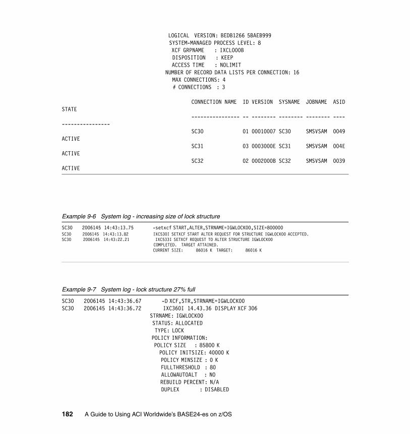
LOGICAL VERSION: BEDB1266 5BAEB999 SYSTEM-MANAGED PROCESS LEVEL: 8 XCF GRPNAME : IXCLO00B DISPOSITION : KEEP ACCESS TIME : NOLIMIT NUMBER OF RECORD DATA LISTS PER CONNECTION: 16 MAX CONNECTIONS: 4 # CONNECTIONS : 3 CONNECTION NAME ID VERSION SYSNAME JOBNAME ASID STATE ---------------- -- -------- -------- -------- ---- ---------------- SC30 01 00010007 SC30 SMSVSAM 0049 ACTIVE SC31 03 0003000E SC31 SMSVSAM 004E ACTIVE SC32 02 0002000B SC32 SMSVSAM 0039 ACTIVE
Example 9-6 System log - increasing size of lock structure
SC30 2006145 14:43:13.75 -setxcf START,ALTER,STRNAME=IGWLOCK00,SIZE=800000 SC30 2006145 14:43:13.82 IXC530I SETXCF START ALTER REQUEST FOR STRUCTURE IGWLOCK00 ACCEPTED. SC30 2006145 14:43:22.21 IXC533I SETXCF REQUEST TO ALTER STRUCTURE IGWLOCK00 COMPLETED. TARGET ATTAINED. CURRENT SIZE: 86016 K TARGET: 86016 K
Example 9-7 System log - lock structure 27% full
SC30 2006145 14:43:36.67 -D XCF,STR,STRNAME=IGWLOCK00 SC30 2006145 14:43:36.72 IXC360I 14.43.36 DISPLAY XCF 306 STRNAME: IGWLOCK00 STATUS: ALLOCATED TYPE: LOCK POLICY INFORMATION: POLICY SIZE : 85800 K POLICY INITSIZE: 40000 K POLICY MINSIZE : 0 K FULLTHRESHOLD : 80 ALLOWAUTOALT : NO REBUILD PERCENT: N/A DUPLEX : DISABLED
182 A Guide to Using ACI Worldwide’s BASE24-es on z/OS
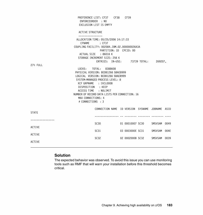
PREFERENCE LIST: CF37 CF38 CF39 ENFORCEORDER : NO EXCLUSION LIST IS EMPTY ACTIVE STRUCTURE ---------------- ALLOCATION TIME: 05/25/2006 14:17:33 CFNAME : CF37 COUPLING FACILITY: 002084.IBM.02.000000026A3A PARTITION: 1D CPCID: 00 ACTUAL SIZE : 86016 K STORAGE INCREMENT SIZE: 256 K ENTRIES: IN-USE: 73739 TOTAL: 269207, 27% FULL LOCKS: TOTAL: 8388608 PHYSICAL VERSION: BEDB1266 5BAEB999 LOGICAL VERSION: BEDB1266 5BAEB999 SYSTEM-MANAGED PROCESS LEVEL: 8 XCF GRPNAME : IXCLO00B DISPOSITION : KEEP ACCESS TIME : NOLIMIT NUMBER OF RECORD DATA LISTS PER CONNECTION: 16 MAX CONNECTIONS: 4 # CONNECTIONS : 3 CONNECTION NAME ID VERSION SYSNAME JOBNAME ASID STATE ---------------- -- -------- -------- -------- ---- ---------------- SC30 01 00010007 SC30 SMSVSAM 0049 ACTIVE SC31 03 0003000E SC31 SMSVSAM 004E ACTIVE SC32 02 0002000B SC32 SMSVSAM 0039 ACTIVE
SolutionThe expected behavior was observed. To avoid this issue you can use monitoring tools such as RMF that will warn your installation before this threshold becomes critical.
Chapter 9. Achieving high availability on z/OS 183
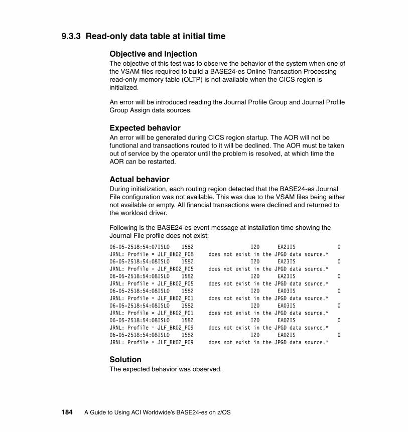
9.3.3 Read-only data table at initial time
Objective and InjectionThe objective of this test was to observe the behavior of the system when one of the VSAM files required to build a BASE24-es Online Transaction Processing read-only memory table (OLTP) is not available when the CICS region is initialized.
An error will be introduced reading the Journal Profile Group and Journal Profile Group Assign data sources.
Expected behaviorAn error will be generated during CICS region startup. The AOR will not be functional and transactions routed to it will be declined. The AOR must be taken out of service by the operator until the problem is resolved, at which time the AOR can be restarted.
Actual behaviorDuring initialization, each routing region detected that the BASE24-es Journal File configuration was not available. This was due to the VSAM files being either not available or empty. All financial transactions were declined and returned to the workload driver.
Following is the BASE24-es event message at installation time showing the Journal File profile does not exist:
06-05-2518:54:07ISLO 1582 I20 EA21IS 0JRNL: Profile = JLF_BK02_P08 does not exist in the JPGD data source.* 06-05-2518:54:08ISLO 1582 I20 EA23IS 0JRNL: Profile = JLF_BK02_P05 does not exist in the JPGD data source.* 06-05-2518:54:08ISLO 1582 I20 EA23IS 0JRNL: Profile = JLF_BK02_P05 does not exist in the JPGD data source.* 06-05-2518:54:08ISLO 1582 I20 EA03IS 0JRNL: Profile = JLF_BK02_P01 does not exist in the JPGD data source.* 06-05-2518:54:08ISLO 1582 I20 EA03IS 0JRNL: Profile = JLF_BK02_P01 does not exist in the JPGD data source.* 06-05-2518:54:08ISLO 1582 I20 EA02IS 0JRNL: Profile = JLF_BK02_P09 does not exist in the JPGD data source.* 06-05-2518:54:08ISLO 1582 I20 EA02IS 0JRNL: Profile = JLF_BK02_P09 does not exist in the JPGD data source.*
SolutionThe expected behavior was observed.
184 A Guide to Using ACI Worldwide’s BASE24-es on z/OS
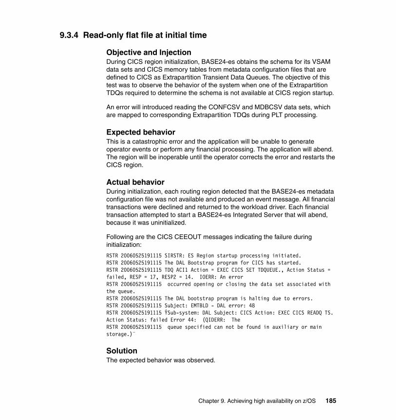
9.3.4 Read-only flat file at initial time
Objective and InjectionDuring CICS region initialization, BASE24-es obtains the schema for its VSAM data sets and CICS memory tables from metadata configuration files that are defined to CICS as Extrapartition Transient Data Queues. The objective of this test was to observe the behavior of the system when one of the Extrapartition TDQs required to determine the schema is not available at CICS region startup.
An error will introduced reading the CONFCSV and MDBCSV data sets, which are mapped to corresponding Extrapartition TDQs during PLT processing.
Expected behaviorThis is a catastrophic error and the application will be unable to generate operator events or perform any financial processing. The application will abend. The region will be inoperable until the operator corrects the error and restarts the CICS region.
Actual behaviorDuring initialization, each routing region detected that the BASE24-es metadata configuration file was not available and produced an event message. All financial transactions were declined and returned to the workload driver. Each financial transaction attempted to start a BASE24-es Integrated Server that will abend, because it was uninitialized.
Following are the CICS CEEOUT messages indicating the failure during initialization:
RSTR 20060525191115 SIRSTR: ES Region startup processing initiated. RSTR 20060525191115 The DAL Bootstrap program for CICS has started. RSTR 20060525191115 TDQ ACI1 Action = EXEC CICS SET TDQUEUE., Action Status = failed, RESP = 17, RESP2 = 14. IOERR: An errorRSTR 20060525191115 occurred opening or closing the data set associated with the queue.RSTR 20060525191115 The DAL bootstrap program is halting due to errors. RSTR 20060525191115 Subject: EMTBLD - DAL error: 48 RSTR 20060525191115 ÝSub-system: DAL Subject: CICS Action: EXEC CICS READQ TS. Action Status: failed Error 44: (QIDERR: TheRSTR 20060525191115 queue specified can not be found in auxiliary or main storage.)¨
SolutionThe expected behavior was observed.
Chapter 9. Achieving high availability on z/OS 185

9.4 BASE24-es application
Here we describe the following BASE24-es application scenarios:
1. Journal file full2. IP client failure3. IP server failure4. Integrated server failure5. Planned application upgrade6. Distributed program link to back-end authorization failure7. Usage file full
In the following sections we explain these scenarios in detail.
9.4.1 Journal file full
Objective and InjectionThe objective of this test was to examine the behavior of the BASE24-es Integrated Server when it encounters a file full condition on one of the BASE24-es financial journal (JRNL) files in a switch-acquired offline-authorized transaction environment; see Figure 9-1 on page 187.
To avoid a lengthy wait while writing a very large number of messages to fill one or more JRNL files, we created the failure by modifying the JCL that creates the JRNL to create artificially small JRNL files. We configured the workload driver to send VDPS messages to be authorized offline by BASE24-es, and we observed the behavior as records were added that exceeded the maximum capacity of the primary JRNL file.
Test configurationIn the initial configuration, transactions flowed from the workload driver. They were authorized by BASE24-es and logged to the primary JRNL file, and responses were returned to the workload driver. There are primary and alternate JRNL files associated with each card issuer configured in the system.
186 A Guide to Using ACI Worldwide’s BASE24-es on z/OS
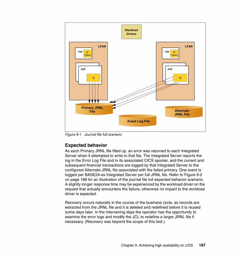
Figure 9-1 Journal file full scenario
Expected behaviorAs each Primary JRNL file filled up, an error was returned to each Integrated Server when it attempted to write to that file. The Integrated Server reports the log in the Error Log File and in its associated CICS spooler, and the current and subsequent financial transactions are logged by that Integrated Server to the configured Alternate JRNL file associated with the failed primary. One event is logged per BASE24-es Integrated Server per full JRNL file. Refer to Figure 9-2 on page 188 for an illustration of the journal file full expected behavior scenario. A slightly longer response time may be experienced by the workload driver on the request that actually encounters the failure; otherwise no impact to the workload driver is expected.
Recovery occurs naturally in the course of the business cycle, as records are extracted from the JRNL file and it is deleted and redefined before it is reused some days later. In the intervening days the operator has the opportunity to examine the error logs and modify the JCL to redefine a larger JRNL file if necessary. (Recovery was beyond the scope of this test.)
TOR
LPAR
AOR
Workload Drivers
Event Log File
IP Client
IS
TOR
LPAR
AOR
IP Client
IS
Primary JRNL File Alternate
JRNL File
Chapter 9. Achieving high availability on z/OS 187

Figure 9-2 Journal file full expected behavior scenario
Actual behaviorWhen the primary Journal File full condition was encountered, the financial transactions were then written to the Alternate Journal File. An event message was produced to indicate this action occurred for each file. During this process, the workload continued uninterrupted.
Following is the BASE24-es event message showing the failure to insert to the Primary Journal File:
06-05-2517:06:34ISLO 1046 E10 EA03IS 1INSERTER: Insert failed for Kernel Inserter Class. Error TABLE FULL: The request failed, no more records could be added to the table. Data Source: JLF_BK02_P00_0 .* 06-05-2517:06:36ISLO 1046 E10 EA13IS 1INSERTER: Insert failed for Kernel Inserter Class. Error TABLE FULL: The request failed, no more records could be added to the table. Data Source: JLF_BK02_P05_5 .*06-05-2517:06:36ISLO 1046 E10 EA13IS 1INSERTER: Insert failed for Kernel Inserter Class. Error TABLE FULL: The requ
TOR
LPAR
AOR
Workload Drivers
Event Log File
IP Client
IS
TOR
LPAR
AOR
IP Client
IS
Primary JRNL File Alternate
JRNL File
188 A Guide to Using ACI Worldwide’s BASE24-es on z/OS
est failed, no more records could be added to the table. Data Source: JLF_BK02_P09_9 .*06-05-2517:06:35ISLO 1046 E10 EA03IS 1INSERTER: Insert failed for Kernel Inserter Class. Error TABLE FULL: The request failed, no more records could be added to the table. Data Source: JLF_BK02_P01_1 .* 02_P04_4 .* INSERTER: Insert failed for Kernel Inserter Class. Error TABLE FULL: The request failed, no more records could be added to the table. Data Source: JLF_BK02_P06_6 .* 06-05-2517:06:34ISLO 1046 E10 EA03IS 1INSERTER: Insert failed for Kernel Inserter Class. Error TABLE FULL: The request failed, no more records could be added to the table. Data Source: JLF_BK06-05-2517:06:34ISLO 1046 E10 EA03IS 1INSERTER: Insert failed for Kernel Inserter Class. Error TABLE FULL: The request failed, no more records could be added to the table. Data Source: JLF_BK02_P03_3 .* 06-05-2517:06:35ISLO 1046 E10 EA03IS 1INSERTER: Insert failed for Kernel Inserter Class. Error TABLE FULL: The request failed, no more records could be added to the table. Data Source: JLF_BK02_P08_8 .* 06-05-2517:06:35ISLO 1046 E10 EA03IS 1INSERTER: Insert failed for Kernel Inserter Class. Error TABLE FULL: The request failed, no more records could be added to the table. Data Source: JLF_BK02_P07_7 .* 06-05-2517:06:36ISLO 1046 E10 EA13IS 1INSERTER: Insert failed for Kernel Inserter Class. Error TABLE FULL: The request failed, no more records could be added to the table. Data Source: JLF_BK02_P02_2 .*
SolutionThe expected behavior was observed.
9.4.2 IP client failure
Objective and InjectionThe objective of this test was to examine the behavior of the BASE24-es system under the spontaneous failure of the BASE24-es IP Client in a switch-acquired transaction environment.
A spontaneous failure was simulated by using CICS CEMT to force purge the IP Client task.
Chapter 9. Achieving high availability on z/OS 189
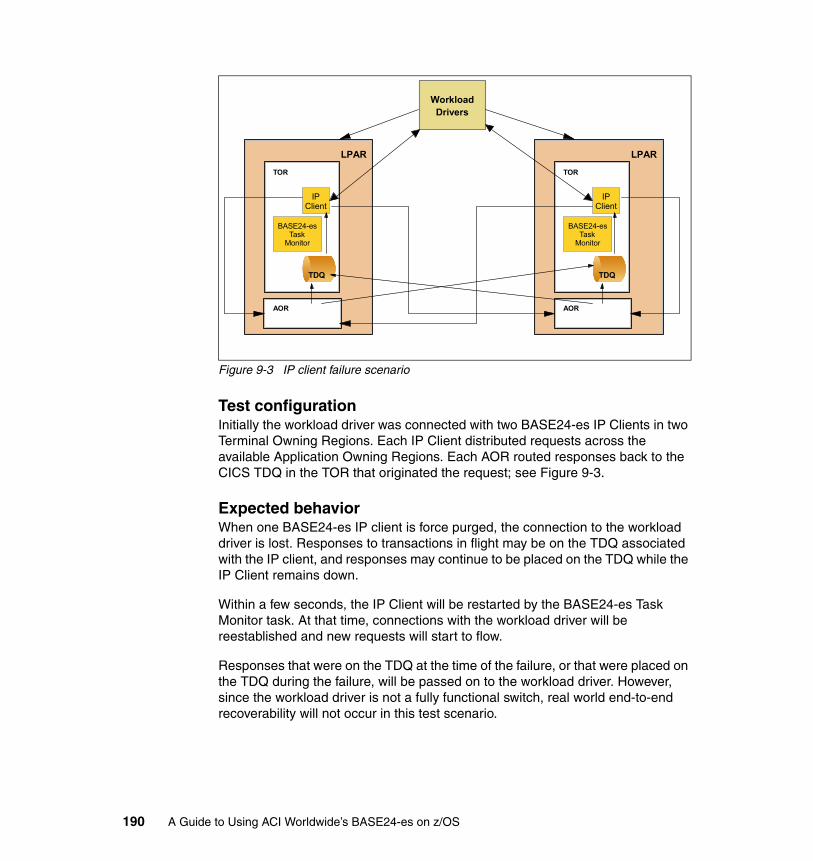
Figure 9-3 IP client failure scenario
Test configurationInitially the workload driver was connected with two BASE24-es IP Clients in two Terminal Owning Regions. Each IP Client distributed requests across the available Application Owning Regions. Each AOR routed responses back to the CICS TDQ in the TOR that originated the request; see Figure 9-3.
Expected behaviorWhen one BASE24-es IP client is force purged, the connection to the workload driver is lost. Responses to transactions in flight may be on the TDQ associated with the IP client, and responses may continue to be placed on the TDQ while the IP Client remains down.
Within a few seconds, the IP Client will be restarted by the BASE24-es Task Monitor task. At that time, connections with the workload driver will be reestablished and new requests will start to flow.
Responses that were on the TDQ at the time of the failure, or that were placed on the TDQ during the failure, will be passed on to the workload driver. However, since the workload driver is not a fully functional switch, real world end-to-end recoverability will not occur in this test scenario.
TOR
LPAR
AOR
Workload Drivers
IP Client
TDQ
BASE24-es Task
Monitor
TOR
LPAR
AOR
IP Client
TDQ
BASE24-es Task
Monitor
190 A Guide to Using ACI Worldwide’s BASE24-es on z/OS
Actual behaviorThree IP clients were each running, processing one-third of the workload. One of the IP clients was force purged. At this point the workload driver recognized the client was down and the workload was reduced by one-third. After the IP client automatically recovered, the full workload was resumed.
The IP process that was purged was restarted with a new CICS transaction ID by the BASE24-es monitor process. Recovery took a few seconds (in our case, seven seconds). During that time, three requests were indicated as timed-out at the workload simulator. There were messages on the IP client queue to be processed when it was purged, as listed here:
IP client task before failure:
Tas(0000058) Tra(T710) Sus Tas Pri( 250 ) Sta(S ) Use(CICSUSER) Uow(BED8505C40B0141)
IP client Failure:
05/23/2006 09:15:03 CICSET01 Transaction T710 abend AEXY in program EZACIC01 term ??? Updates to local recoverable resources will be backed out.
IP client recovery:
06-05-2309:15:10TCPSERVNACI.8000000.10000 I1000 ET01T710 0
TCP/IP Main, long term task starting*
IP client Task after recovery:
Tas(0001592) Tra(T710) Sus Tas Pri( 250 ) Sta(S ) Use(CICSUSER) Uow(BED84B153BE63346)
SolutionThe expected behavior was observed.
9.4.3 IP Server failure
Objective and InjectionThe objective of this test was to examine the behavior of the BASE24-es system under the spontaneous failure of the BASE24-es IP Server in a POS device-acquired transaction environment.
A spontaneous failure was simulated by using CICS CEMT to force purge the IP Server task.
Note: Task 0000058 had been replaced by task 0001592.
Chapter 9. Achieving high availability on z/OS 191
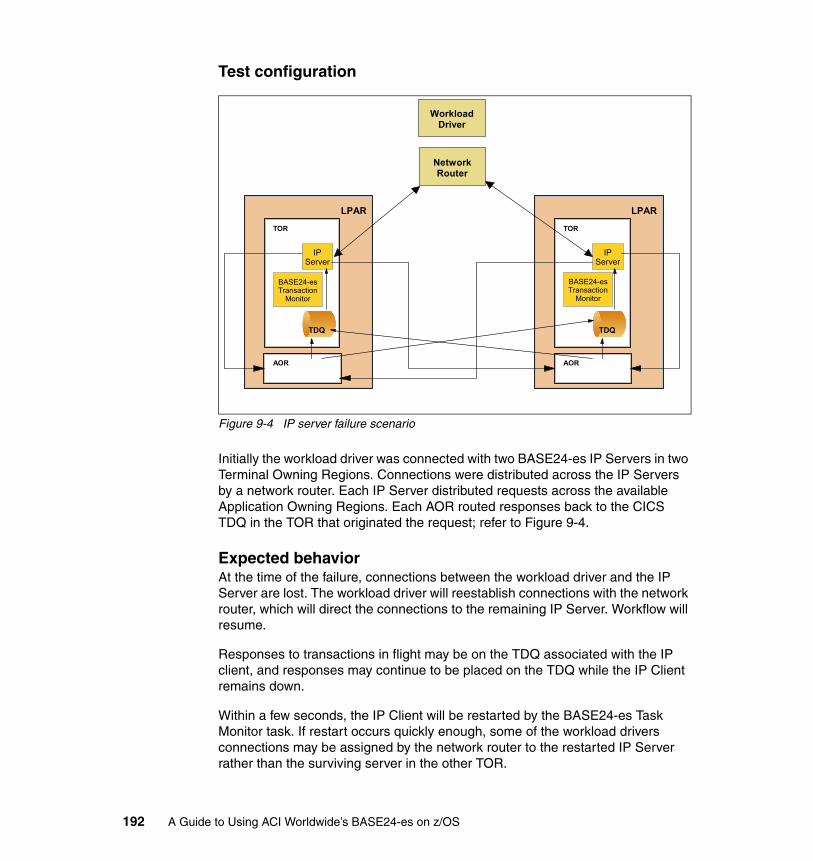
Test configuration
Figure 9-4 IP server failure scenario
Initially the workload driver was connected with two BASE24-es IP Servers in two Terminal Owning Regions. Connections were distributed across the IP Servers by a network router. Each IP Server distributed requests across the available Application Owning Regions. Each AOR routed responses back to the CICS TDQ in the TOR that originated the request; refer to Figure 9-4.
Expected behaviorAt the time of the failure, connections between the workload driver and the IP Server are lost. The workload driver will reestablish connections with the network router, which will direct the connections to the remaining IP Server. Workflow will resume.
Responses to transactions in flight may be on the TDQ associated with the IP client, and responses may continue to be placed on the TDQ while the IP Client remains down.
Within a few seconds, the IP Client will be restarted by the BASE24-es Task Monitor task. If restart occurs quickly enough, some of the workload drivers connections may be assigned by the network router to the restarted IP Server rather than the surviving server in the other TOR.
TOR
LPAR
AOR
Network Router
IP Server
TDQ
BASE24-es Transaction
Monitor
TOR
LPAR
AOR
IP Server
TDQ
BASE24-es Transaction
Monitor
Workload Driver
192 A Guide to Using ACI Worldwide’s BASE24-es on z/OS

Responses that were on the TDQ at the time of the failure, or that were placed on the TDQ during the failure, will be returned to one of the available AORs for failure processing, resulting in a financial reversal being logged to the appropriate financial journal file. The workload driver will experience late or no responses. However, since the workload driver is not a fully functional POS device, real world end-to-end recoverability will not occur in this test scenario.
Actual behaviorThree IP servers were running, each processing one-third of the workload. One of the IP servers was force purged. At this point the workload driver issued a new client connection request and the connection was established to one of the remaining IP servers. The workload driver showed no interruption to the workload.
The IP process that was purged was restarted with a new CICS transaction ID by the BASE24-es monitor process and was available to accept new connections within few seconds (in our case, eleven seconds).
During that time, the following event was generated:
06-05-2309:43:49ISLO 2031 E180 EA11IS 0SPDH: Failed message received for Channel ID S000020153 with insufficient PAN/Amount/Sequence Number data to be processed.*
Due to a limitation in the workload driver, sequence number processing was disabled in the BASE24-es SPDH component. Without sequence number processing, the above event was generated. When sequence number processing is enabled, this event would not be generated and this financial transaction will result in a reversal.
IP client task before failure:
Tas(0000063) Tra(T701) Sus Tas Pri( 250 ) Sta(S ) Use(CICSUSER) Uow(BED8505D8D1F589B)
IP client Failure:
05/23/2006 09:43:38 CICSET01 Transaction T701 abend AEXY in program EZACIC01 term ??? Updates to local recoverable resources will be backed out.
IP client recovery:
06-05-2309:43:49TCPSERVNACI.8000000.10000 I1000 ET01T701 0TCP/IP Main, long term task starting*
IP client Task after recovery:
Tas(0000779) Tra(T701) Sus Tas Pri( 250 ) Sta(S ) Use(CICSUSER) Uow(BED8517C1A4B15D6)
Chapter 9. Achieving high availability on z/OS 193
SolutionThe expected behavior was observed.
9.4.4 Integrated Server failure
Objective and InjectionThe objective of this test was to examine the behavior of the BASE24-es system under the spontaneous failure of one BASE24-es Integrated Server (IS) task in a switch-acquired offline-authorized transaction environment. The spontaneous failure was simulated by using CICS CEMT to force purge one of the IS tasks in one AOR.
Test configurationAt inception, IP clients in the TORs have connected to the workload driver, and transactions are being distributed across the IS TDQs in the available AORs and are being authorized. When one IS task is force-purged, the remaining IS tasks in the AOR continue processing messages from the TDQ. (Sufficient IS tasks are configured to assure the loss of any one task will not affect the throughput capability of the AOR.)
Within a few seconds the BASE24-es Task Monitor will restart the failed IS task and processing will return to normal.
If a message is being processed by the failed IS at the time of failure, uncommitted database updates will be backed out by CICS, assuring financial integrity within the BASE24-es system.
If a message is being processed by the failed IS at the time of failure, the message will time out at the workload driver.Figure 9-5 on page 195 illustrates the Integrated Server failure scenario.
Because the workload driver is not a fully functional switch, end-to-end recovery will not occur. However, in the real world, end-to-end recovery would assure financial integrity between the acquiring interface and BASE24-es.
Note: Task 0000063 had been replaced by task 0000779.
194 A Guide to Using ACI Worldwide’s BASE24-es on z/OS
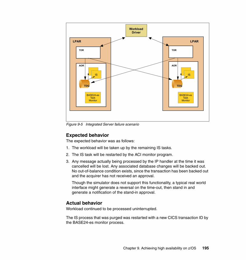
Figure 9-5 Integrated Server failure scenario
Expected behaviorThe expected behavior was as follows:
1. The workload will be taken up by the remaining IS tasks.
2. The IS task will be restarted by the ACI monitor program.
3. Any message actually being processed by the IP handler at the time it was cancelled will be lost. Any associated database changes will be backed out. No out-of-balance condition exists, since the transaction has been backed out and the acquirer has not received an approval.
Though the simulator does not support this functionality, a typical real world interface might generate a reversal on the time-out, then stand in and generate a notification of the stand-in approval.
Actual behaviorWorkload continued to be processed uninterrupted.
The IS process that was purged was restarted with a new CICS transaction ID by the BASE24-es monitor process.
TOR
LPAR
AOR
Workload Driver
IS
TDQ
BASE24-es Task
Monitor
TOR
LPAR
AOR
IS
BASE24-es Task
Monitor
TDQ TDQ
IS IS
Chapter 9. Achieving high availability on z/OS 195
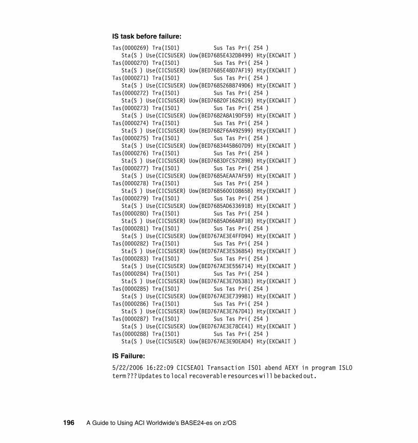
IS task before failure:
Tas(0000269) Tra(IS01) Sus Tas Pri( 254 ) Sta(S ) Use(CICSUSER) Uow(BED7685E432DB499) Hty(EKCWAIT )Tas(0000270) Tra(IS01) Sus Tas Pri( 254 ) Sta(S ) Use(CICSUSER) Uow(BED7685E48D7AF19) Hty(EKCWAIT )Tas(0000271) Tra(IS01) Sus Tas Pri( 254 ) Sta(S ) Use(CICSUSER) Uow(BED768526B8749D6) Hty(EKCWAIT )Tas(0000272) Tra(IS01) Sus Tas Pri( 254 ) Sta(S ) Use(CICSUSER) Uow(BED76820F1626C19) Hty(EKCWAIT )Tas(0000273) Tra(IS01) Sus Tas Pri( 254 ) Sta(S ) Use(CICSUSER) Uow(BED7682A8A19DF59) Hty(EKCWAIT )Tas(0000274) Tra(IS01) Sus Tas Pri( 254 ) Sta(S ) Use(CICSUSER) Uow(BED7682F6A492599) Hty(EKCWAIT )Tas(0000275) Tra(IS01) Sus Tas Pri( 254 ) Sta(S ) Use(CICSUSER) Uow(BED7683445B607D9) Hty(EKCWAIT )Tas(0000276) Tra(IS01) Sus Tas Pri( 254 ) Sta(S ) Use(CICSUSER) Uow(BED7683DFC57C89B) Hty(EKCWAIT )Tas(0000277) Tra(IS01) Sus Tas Pri( 254 ) Sta(S ) Use(CICSUSER) Uow(BED7685AEAA7AF59) Hty(EKCWAIT )Tas(0000278) Tra(IS01) Sus Tas Pri( 254 ) Sta(S ) Use(CICSUSER) Uow(BED768560010865B) Hty(EKCWAIT )Tas(0000279) Tra(IS01) Sus Tas Pri( 254 ) Sta(S ) Use(CICSUSER) Uow(BED7685AD633691B) Hty(EKCWAIT )Tas(0000280) Tra(IS01) Sus Tas Pri( 254 ) Sta(S ) Use(CICSUSER) Uow(BED7685AD66ABF1B) Hty(EKCWAIT )Tas(0000281) Tra(IS01) Sus Tas Pri( 254 ) Sta(S ) Use(CICSUSER) Uow(BED767AE3E4FFD94) Hty(EKCWAIT )Tas(0000282) Tra(IS01) Sus Tas Pri( 254 ) Sta(S ) Use(CICSUSER) Uow(BED767AE3E536854) Hty(EKCWAIT )Tas(0000283) Tra(IS01) Sus Tas Pri( 254 ) Sta(S ) Use(CICSUSER) Uow(BED767AE3E556714) Hty(EKCWAIT )Tas(0000284) Tra(IS01) Sus Tas Pri( 254 ) Sta(S ) Use(CICSUSER) Uow(BED767AE3E705381) Hty(EKCWAIT )Tas(0000285) Tra(IS01) Sus Tas Pri( 254 ) Sta(S ) Use(CICSUSER) Uow(BED767AE3E739981) Hty(EKCWAIT )Tas(0000286) Tra(IS01) Sus Tas Pri( 254 ) Sta(S ) Use(CICSUSER) Uow(BED767AE3E767D41) Hty(EKCWAIT )Tas(0000287) Tra(IS01) Sus Tas Pri( 254 ) Sta(S ) Use(CICSUSER) Uow(BED767AE3E78CE41) Hty(EKCWAIT )Tas(0000288) Tra(IS01) Sus Tas Pri( 254 ) Sta(S ) Use(CICSUSER) Uow(BED767AE3E9DEAD4) Hty(EKCWAIT )
IS Failure:
5/22/2006 16:22:09 CICSEA01 Transaction IS01 abend AEXY in program ISLO term ??? Updates to local recoverable resources will be backed out.
196 A Guide to Using ACI Worldwide’s BASE24-es on z/OS
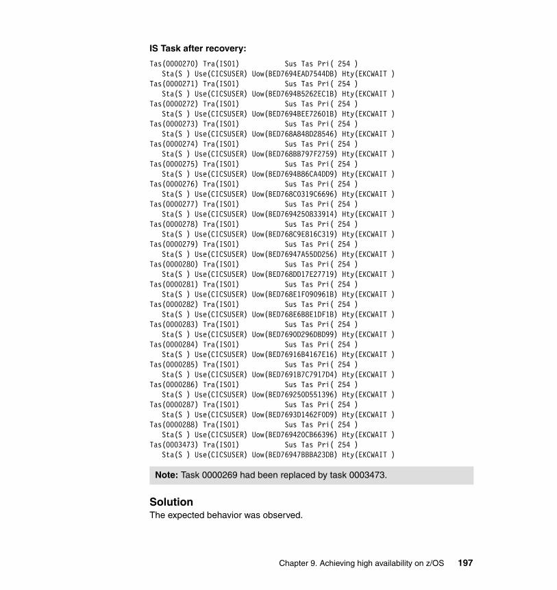
IS Task after recovery:
Tas(0000270) Tra(IS01) Sus Tas Pri( 254 ) Sta(S ) Use(CICSUSER) Uow(BED7694EAD7544DB) Hty(EKCWAIT )Tas(0000271) Tra(IS01) Sus Tas Pri( 254 ) Sta(S ) Use(CICSUSER) Uow(BED7694B5262EC1B) Hty(EKCWAIT )Tas(0000272) Tra(IS01) Sus Tas Pri( 254 ) Sta(S ) Use(CICSUSER) Uow(BED7694BEE72601B) Hty(EKCWAIT )Tas(0000273) Tra(IS01) Sus Tas Pri( 254 ) Sta(S ) Use(CICSUSER) Uow(BED768A848D28546) Hty(EKCWAIT )Tas(0000274) Tra(IS01) Sus Tas Pri( 254 ) Sta(S ) Use(CICSUSER) Uow(BED768BB797F2759) Hty(EKCWAIT )Tas(0000275) Tra(IS01) Sus Tas Pri( 254 ) Sta(S ) Use(CICSUSER) Uow(BED7694B86CA4DD9) Hty(EKCWAIT )Tas(0000276) Tra(IS01) Sus Tas Pri( 254 ) Sta(S ) Use(CICSUSER) Uow(BED768C0319C6696) Hty(EKCWAIT )Tas(0000277) Tra(IS01) Sus Tas Pri( 254 ) Sta(S ) Use(CICSUSER) Uow(BED7694250833914) Hty(EKCWAIT )Tas(0000278) Tra(IS01) Sus Tas Pri( 254 ) Sta(S ) Use(CICSUSER) Uow(BED768C9E816C319) Hty(EKCWAIT )Tas(0000279) Tra(IS01) Sus Tas Pri( 254 ) Sta(S ) Use(CICSUSER) Uow(BED76947A55DD256) Hty(EKCWAIT )Tas(0000280) Tra(IS01) Sus Tas Pri( 254 ) Sta(S ) Use(CICSUSER) Uow(BED768DD17E27719) Hty(EKCWAIT )Tas(0000281) Tra(IS01) Sus Tas Pri( 254 ) Sta(S ) Use(CICSUSER) Uow(BED768E1F090961B) Hty(EKCWAIT )Tas(0000282) Tra(IS01) Sus Tas Pri( 254 ) Sta(S ) Use(CICSUSER) Uow(BED768E6B8E1DF1B) Hty(EKCWAIT )Tas(0000283) Tra(IS01) Sus Tas Pri( 254 ) Sta(S ) Use(CICSUSER) Uow(BED7690D296DBD99) Hty(EKCWAIT )Tas(0000284) Tra(IS01) Sus Tas Pri( 254 ) Sta(S ) Use(CICSUSER) Uow(BED76916B4167E16) Hty(EKCWAIT )Tas(0000285) Tra(IS01) Sus Tas Pri( 254 ) Sta(S ) Use(CICSUSER) Uow(BED7691B7C7917D4) Hty(EKCWAIT )Tas(0000286) Tra(IS01) Sus Tas Pri( 254 ) Sta(S ) Use(CICSUSER) Uow(BED769250D551396) Hty(EKCWAIT )Tas(0000287) Tra(IS01) Sus Tas Pri( 254 ) Sta(S ) Use(CICSUSER) Uow(BED7693D1462F0D9) Hty(EKCWAIT )Tas(0000288) Tra(IS01) Sus Tas Pri( 254 ) Sta(S ) Use(CICSUSER) Uow(BED769420CB66396) Hty(EKCWAIT )Tas(0003473) Tra(IS01) Sus Tas Pri( 254 ) Sta(S ) Use(CICSUSER) Uow(BED76947BBBA23DB) Hty(EKCWAIT )
SolutionThe expected behavior was observed.
Note: Task 0000269 had been replaced by task 0003473.
Chapter 9. Achieving high availability on z/OS 197
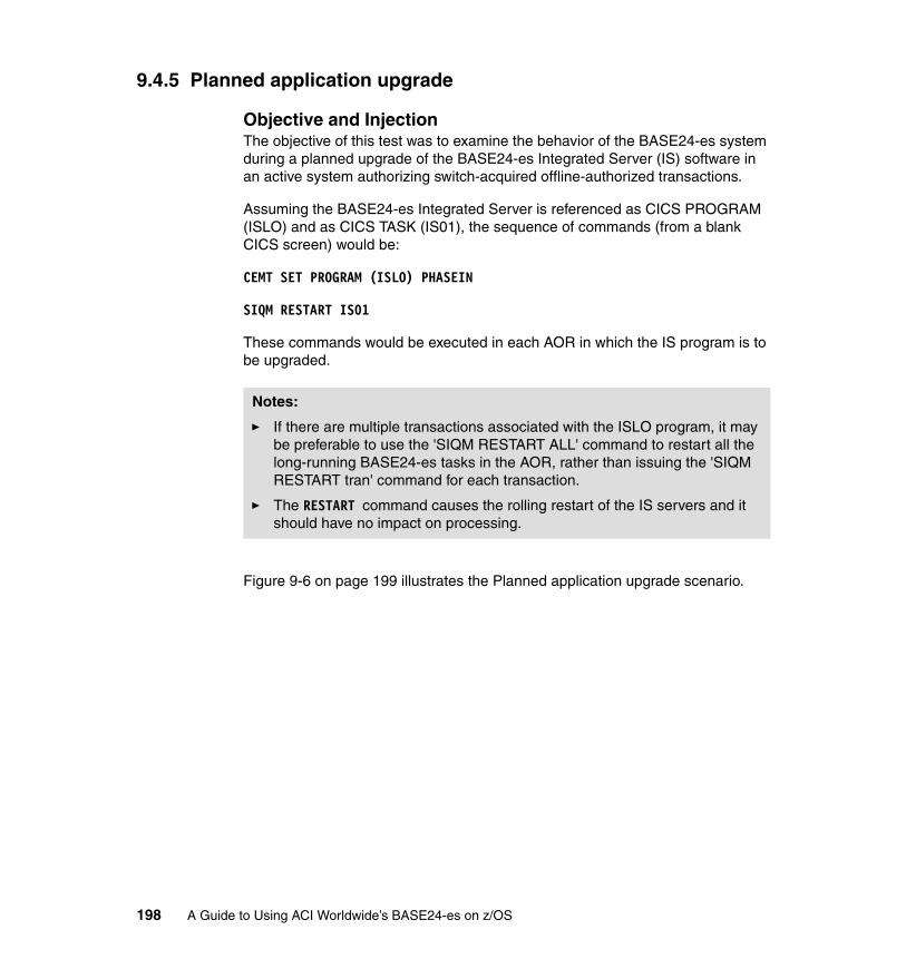
9.4.5 Planned application upgrade
Objective and InjectionThe objective of this test was to examine the behavior of the BASE24-es system during a planned upgrade of the BASE24-es Integrated Server (IS) software in an active system authorizing switch-acquired offline-authorized transactions.
Assuming the BASE24-es Integrated Server is referenced as CICS PROGRAM (ISLO) and as CICS TASK (IS01), the sequence of commands (from a blank CICS screen) would be:
CEMT SET PROGRAM (ISLO) PHASEIN
SIQM RESTART IS01
These commands would be executed in each AOR in which the IS program is to be upgraded.
Figure 9-6 on page 199 illustrates the Planned application upgrade scenario.
Notes:
� If there are multiple transactions associated with the ISLO program, it may be preferable to use the 'SIQM RESTART ALL' command to restart all the long-running BASE24-es tasks in the AOR, rather than issuing the 'SIQM RESTART tran' command for each transaction.
� The RESTART command causes the rolling restart of the IS servers and it should have no impact on processing.
198 A Guide to Using ACI Worldwide’s BASE24-es on z/OS

Test configuration
Figure 9-6 Planned application upgrade scenario
Expected behaviorSetting the ISLO program to PHASEIN specifies that a new copy of the program is brought into CICS memory. Because the RESTART command causes the IS01 tasks to stop and restart, they are restarted with the new version of the ISLO program.
The RESTART command causes a rolling restart so that instances of the task are stopped and restarted sequentially outside of a financial transaction. Some minor increases in response time will occur as a result of the RESTART command. No impact to the financial integrity of the system is expected.
Actual behaviorWorkload continued to be processed uninterrupted.
The IS processes before the restart command was issued:
Tas(0000262) Tra(IS01) Sus Tas Pri( 254 ) Sta(S ) Use(CICSUSER) Uow(BED76A030857CE99) Hty(EKCWAIT )Tas(0000263) Tra(IS01) Sus Tas Pri( 254 )
TOR
LPAR
AOR
Workload Driver
IS
TDQ
BASE24-es Task
Monitor
TOR
LPAR
AOR
IS
BASE24-es Task
Monitor
TDQ TDQ
IS IS
Chapter 9. Achieving high availability on z/OS 199
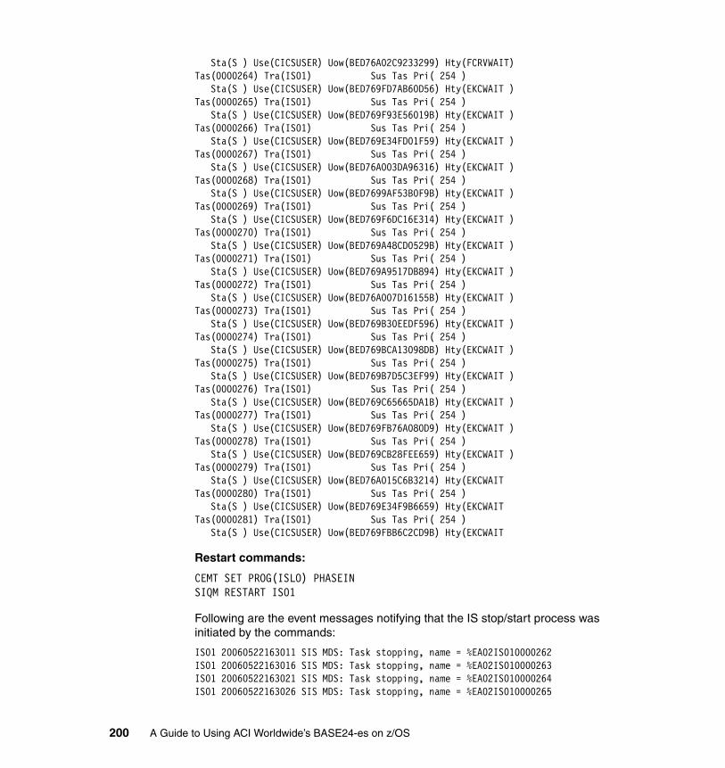
Sta(S ) Use(CICSUSER) Uow(BED76A02C9233299) Hty(FCRVWAIT)Tas(0000264) Tra(IS01) Sus Tas Pri( 254 ) Sta(S ) Use(CICSUSER) Uow(BED769FD7AB60D56) Hty(EKCWAIT )Tas(0000265) Tra(IS01) Sus Tas Pri( 254 ) Sta(S ) Use(CICSUSER) Uow(BED769F93E56019B) Hty(EKCWAIT )Tas(0000266) Tra(IS01) Sus Tas Pri( 254 ) Sta(S ) Use(CICSUSER) Uow(BED769E34FD01F59) Hty(EKCWAIT )Tas(0000267) Tra(IS01) Sus Tas Pri( 254 ) Sta(S ) Use(CICSUSER) Uow(BED76A003DA96316) Hty(EKCWAIT )Tas(0000268) Tra(IS01) Sus Tas Pri( 254 ) Sta(S ) Use(CICSUSER) Uow(BED7699AF53B0F9B) Hty(EKCWAIT )Tas(0000269) Tra(IS01) Sus Tas Pri( 254 ) Sta(S ) Use(CICSUSER) Uow(BED769F6DC16E314) Hty(EKCWAIT )Tas(0000270) Tra(IS01) Sus Tas Pri( 254 ) Sta(S ) Use(CICSUSER) Uow(BED769A48CD0529B) Hty(EKCWAIT )Tas(0000271) Tra(IS01) Sus Tas Pri( 254 ) Sta(S ) Use(CICSUSER) Uow(BED769A9517DB894) Hty(EKCWAIT )Tas(0000272) Tra(IS01) Sus Tas Pri( 254 ) Sta(S ) Use(CICSUSER) Uow(BED76A007D16155B) Hty(EKCWAIT )Tas(0000273) Tra(IS01) Sus Tas Pri( 254 ) Sta(S ) Use(CICSUSER) Uow(BED769B30EEDF596) Hty(EKCWAIT )Tas(0000274) Tra(IS01) Sus Tas Pri( 254 ) Sta(S ) Use(CICSUSER) Uow(BED769BCA13098DB) Hty(EKCWAIT )Tas(0000275) Tra(IS01) Sus Tas Pri( 254 ) Sta(S ) Use(CICSUSER) Uow(BED769B7D5C3EF99) Hty(EKCWAIT )Tas(0000276) Tra(IS01) Sus Tas Pri( 254 ) Sta(S ) Use(CICSUSER) Uow(BED769C65665DA1B) Hty(EKCWAIT )Tas(0000277) Tra(IS01) Sus Tas Pri( 254 ) Sta(S ) Use(CICSUSER) Uow(BED769FB76A080D9) Hty(EKCWAIT )Tas(0000278) Tra(IS01) Sus Tas Pri( 254 ) Sta(S ) Use(CICSUSER) Uow(BED769CB28FEE659) Hty(EKCWAIT )Tas(0000279) Tra(IS01) Sus Tas Pri( 254 ) Sta(S ) Use(CICSUSER) Uow(BED76A015C6B3214) Hty(EKCWAIT Tas(0000280) Tra(IS01) Sus Tas Pri( 254 ) Sta(S ) Use(CICSUSER) Uow(BED769E34F9B6659) Hty(EKCWAIT Tas(0000281) Tra(IS01) Sus Tas Pri( 254 ) Sta(S ) Use(CICSUSER) Uow(BED769FBB6C2CD9B) Hty(EKCWAIT
Restart commands:
CEMT SET PROG(ISLO) PHASEINSIQM RESTART IS01
Following are the event messages notifying that the IS stop/start process was initiated by the commands:
IS01 20060522163011 SIS MDS: Task stopping, name = %EA02IS010000262IS01 20060522163016 SIS MDS: Task stopping, name = %EA02IS010000263IS01 20060522163021 SIS MDS: Task stopping, name = %EA02IS010000264IS01 20060522163026 SIS MDS: Task stopping, name = %EA02IS010000265
200 A Guide to Using ACI Worldwide’s BASE24-es on z/OS
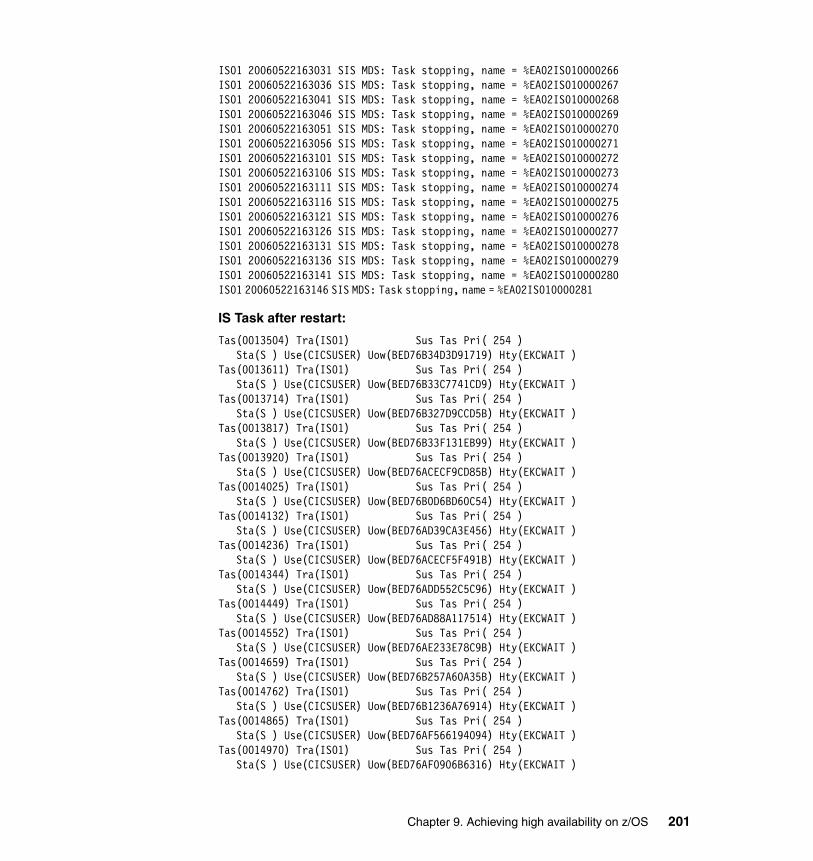
IS01 20060522163031 SIS MDS: Task stopping, name = %EA02IS010000266IS01 20060522163036 SIS MDS: Task stopping, name = %EA02IS010000267IS01 20060522163041 SIS MDS: Task stopping, name = %EA02IS010000268IS01 20060522163046 SIS MDS: Task stopping, name = %EA02IS010000269IS01 20060522163051 SIS MDS: Task stopping, name = %EA02IS010000270IS01 20060522163056 SIS MDS: Task stopping, name = %EA02IS010000271IS01 20060522163101 SIS MDS: Task stopping, name = %EA02IS010000272IS01 20060522163106 SIS MDS: Task stopping, name = %EA02IS010000273IS01 20060522163111 SIS MDS: Task stopping, name = %EA02IS010000274IS01 20060522163116 SIS MDS: Task stopping, name = %EA02IS010000275IS01 20060522163121 SIS MDS: Task stopping, name = %EA02IS010000276IS01 20060522163126 SIS MDS: Task stopping, name = %EA02IS010000277IS01 20060522163131 SIS MDS: Task stopping, name = %EA02IS010000278IS01 20060522163136 SIS MDS: Task stopping, name = %EA02IS010000279IS01 20060522163141 SIS MDS: Task stopping, name = %EA02IS010000280IS01 20060522163146 SIS MDS: Task stopping, name = %EA02IS010000281
IS Task after restart:
Tas(0013504) Tra(IS01) Sus Tas Pri( 254 ) Sta(S ) Use(CICSUSER) Uow(BED76B34D3D91719) Hty(EKCWAIT )Tas(0013611) Tra(IS01) Sus Tas Pri( 254 ) Sta(S ) Use(CICSUSER) Uow(BED76B33C7741CD9) Hty(EKCWAIT )Tas(0013714) Tra(IS01) Sus Tas Pri( 254 ) Sta(S ) Use(CICSUSER) Uow(BED76B327D9CCD5B) Hty(EKCWAIT )Tas(0013817) Tra(IS01) Sus Tas Pri( 254 ) Sta(S ) Use(CICSUSER) Uow(BED76B33F131EB99) Hty(EKCWAIT )Tas(0013920) Tra(IS01) Sus Tas Pri( 254 ) Sta(S ) Use(CICSUSER) Uow(BED76ACECF9CD85B) Hty(EKCWAIT )Tas(0014025) Tra(IS01) Sus Tas Pri( 254 ) Sta(S ) Use(CICSUSER) Uow(BED76B0D6BD60C54) Hty(EKCWAIT )Tas(0014132) Tra(IS01) Sus Tas Pri( 254 ) Sta(S ) Use(CICSUSER) Uow(BED76AD39CA3E456) Hty(EKCWAIT )Tas(0014236) Tra(IS01) Sus Tas Pri( 254 ) Sta(S ) Use(CICSUSER) Uow(BED76ACECF5F491B) Hty(EKCWAIT )Tas(0014344) Tra(IS01) Sus Tas Pri( 254 ) Sta(S ) Use(CICSUSER) Uow(BED76ADD552C5C96) Hty(EKCWAIT )Tas(0014449) Tra(IS01) Sus Tas Pri( 254 ) Sta(S ) Use(CICSUSER) Uow(BED76AD88A117514) Hty(EKCWAIT )Tas(0014552) Tra(IS01) Sus Tas Pri( 254 ) Sta(S ) Use(CICSUSER) Uow(BED76AE233E78C9B) Hty(EKCWAIT )Tas(0014659) Tra(IS01) Sus Tas Pri( 254 ) Sta(S ) Use(CICSUSER) Uow(BED76B257A60A35B) Hty(EKCWAIT )Tas(0014762) Tra(IS01) Sus Tas Pri( 254 ) Sta(S ) Use(CICSUSER) Uow(BED76B1236A76914) Hty(EKCWAIT )Tas(0014865) Tra(IS01) Sus Tas Pri( 254 ) Sta(S ) Use(CICSUSER) Uow(BED76AF566194094) Hty(EKCWAIT )Tas(0014970) Tra(IS01) Sus Tas Pri( 254 ) Sta(S ) Use(CICSUSER) Uow(BED76AF0906B6316) Hty(EKCWAIT )
Chapter 9. Achieving high availability on z/OS 201
Tas(0015073) Tra(IS01) Sus Tas Pri( 254 ) Sta(S ) Use(CICSUSER) Uow(BED76AFF04629019) Hty(EKCWAIT )Tas(0015178) Tra(IS01) Sus Tas Pri( 254 ) Sta(S ) Use(CICSUSER) Uow(BED76AFA3613671B) Hty(EKCWAIT ) Tas(0015281) Tra(IS01) Sus Tas Pri( 254 ) Sta(S ) Use(CICSUSER) Uow(BED76B34099C945B) Hty(EKCWAIT ) Tas(0015388) Tra(IS01) Sus Tas Pri( 254 ) Sta(S ) Use(CICSUSER) Uow(BED76B2F31994059) Hty(EKCWAIT ) Tas(0015493) Tra(IS01) Sus Tas Pri( 254 ) Sta(S ) Use(CICSUSER) Uow(BED76AD392BC8E59) Hty(EKCWAIT )
SolutionThe expected behavior was observed.
9.4.6 Remote program link to back-end authorization failure
Objective and InjectionThe objective of this test was to examine the behavior of the BASE24-es system under the failure of a CICSLINK to a customer’s back-end host system.
The assumption was that there will be at least two AORs running the customer's back-end host system, and that BASE24-es will route online authorizations to those systems via remote LINK. At least two BASE24-es stations will be configured, each associated in the BASE24-es synchronous destination map file (SYDMF) with a separate remote program definition in a separate authorizing region. Three regions running a host simulator are available. The failure will be injected by canceling one of the back-end AORs. Figure 9-7 on page 203 illustrates this scenario.
Note: All task IDs have changed.
Note: We chose to test this scenario using the alternate routing capabilities of the BASE24-es application, rather than using the equally valid approach of configuring a CIVSplex distributed link.
202 A Guide to Using ACI Worldwide’s BASE24-es on z/OS
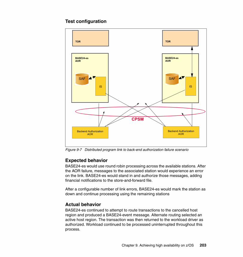
Test configuration
Figure 9-7 Distributed program link to back-end authorization failure scenario
Expected behaviorBASE24-es would use round robin processing across the available stations. After the AOR failure, messages to the associated station would experience an error on the link. BASE24-es would stand in and authorize those messages, adding financial notifications to the store-and-forward file.
After a configurable number of link errors, BASE24-es would mark the station as down and continue processing using the remaining stations
Actual behaviorBASE24-es continued to attempt to route transactions to the cancelled host region and produced a BASE24-event message. Alternate routing selected an active host region. The transaction was then returned to the workload driver as authorized. Workload continued to be processed uninterrupted throughout this process.
TDQ
TOR
BASE24-es AOR
IS
Backend Authorization AOR
SAF
CPSM
TDQ
TOR
BASE24-es AOR
IS
Backend Authorization AOR
SAF
Chapter 9. Achieving high availability on z/OS 203
Note: If you do not wish to see the BASE24-event message produced when an attempt is made to route to a cancelled host region, use the BASE24-es Event management system to control the suppression of this message.
Following is the BASE24-es event message showing inability to link to host:
06-05-2611:38:35ISLO 1042 I110 EA11IS 1SENDMSG: Unable to send and /or receive a message from the SIS Send Class. Result 12 returned.ÝSub-system: CICS Subject: SIMIATT0 Action: EXEC CICS LINK Action Status: failed Error 53: (SYSIDERR: 28 - The remote system specified in SYSID is not in service.)¨*
SolutionThe expected behavior was observed.
9.4.7 Usage file full
Objective and InjectionThe objective of this test was to examine the behavior of the BASE24-es Integrated Server when it encounters a file full condition on the BASE24-es Usage files in a switch-acquired offline-authorized transaction environment.
The Usage file contains one record per card per usage period. The error was created by an extended high-volume run with random cards.
Test configurationIn the initial configuration, transactions flow from the workload driver. They are authorized by BASE24-es, logged to the primary JRNL file, and responses are returned to the workload driver. There are primary and alternate JRNL files associated with each card issuer configured in the system. Figure 9-8 on page 205 illustrates the Usage file full scenario.
204 A Guide to Using ACI Worldwide’s BASE24-es on z/OS
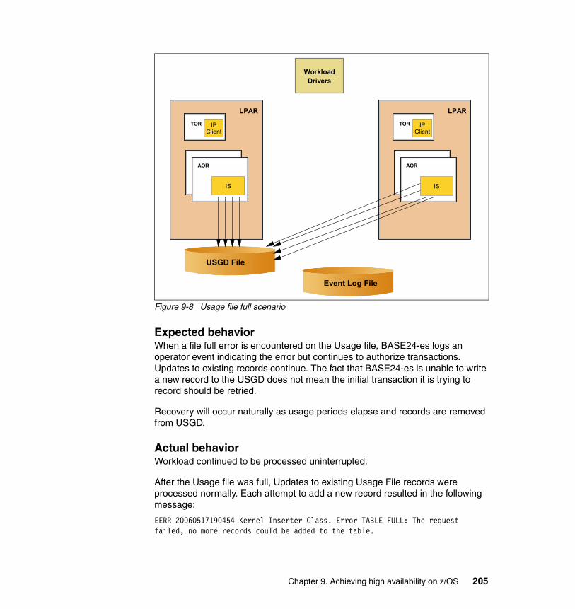
Figure 9-8 Usage file full scenario
Expected behaviorWhen a file full error is encountered on the Usage file, BASE24-es logs an operator event indicating the error but continues to authorize transactions. Updates to existing records continue. The fact that BASE24-es is unable to write a new record to the USGD does not mean the initial transaction it is trying to record should be retried.
Recovery will occur naturally as usage periods elapse and records are removed from USGD.
Actual behaviorWorkload continued to be processed uninterrupted.
After the Usage file was full, Updates to existing Usage File records were processed normally. Each attempt to add a new record resulted in the following message:
EERR 20060517190454 Kernel Inserter Class. Error TABLE FULL: The request failed, no more records could be added to the table.
TOR
LPAR
AOR
Workload Drivers
Event Log File
IP Client
IS
TOR
LPAR
AOR
IP Client
IS
USGD File
Chapter 9. Achieving high availability on z/OS 205

EERR 20060517190454 Data Source: USAGE .ÝSub-system: FILE_PARTITION Subject: USAGEEERR 20060517190454 Action: Row Insert Action Status: FAILED Error Assign Entry Data Source: (insertion failed)EERR 20060517190454 ¨
SolutionIf this error is encountered frequently, it may be necessary to take an outage to resize the system, so it is good practice to assure that the usage file is adequately sized initially.
9.5 Hardware
This section covers the following hardware failure scenarios:
1. Central Processor (CP) failure2. CPC failure/LPAR failure3. Coupling Facility (CF) failure
9.5.1 Central Processor (CP) failure
Objective and InjectionThe objective of this scenario was to demonstrate that the application BASE24-es is able to continue working even if a CP failure occurs.
Because our LPARs are symmetrical, we can perform this test on any LPAR and the behaviors should be similar on all of them. In our case, we used SC31. We initiate this test by removing a CP using the CF CP(0),offline command.
ConfigurationWhen we issue the command D M=CPU on SC31, we can see in the response that the LPAR is running on two processors (CPs). For this reason, taking one processor offline should not affect the functionality of the application. If this was the only or last processor in the LPAR, a failure of the processor will be presented similarly as an LPAR failure or CPC failure.
IEE174I 13.52.53 DISPLAY M 101 PROCESSOR STATUS ID CPU SERIAL 00 + 24991E2094 01 + 24991E2094 02 - 03 -
206 A Guide to Using ACI Worldwide’s BASE24-es on z/OS
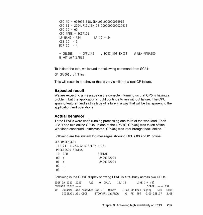
CPC ND = 002094.S18.IBM.02.00000002991E CPC SI = 2094.712.IBM.02.000000000002991E CPC ID = 00 CPC NAME = SCZP101 LP NAME = A24 LP ID = 24 CSS ID = 2 MIF ID = 4 + ONLINE - OFFLINE . DOES NOT EXIST W WLM-MANAGED N NOT AVAILABLE
To initiate the test, we issued the following command from SC31:
CF CPU(0), offline
This will result in a behavior that is very similar to a real CP failure.
Expected resultWe are expecting a message on the console informing us that CP0 is having a problem, but the application should continue to run without failure. The CPU sparing feature handles this type of failure in a way that will be transparent to the application and operations.
Actual behaviorThree LPARs were each running processing one-third of the workload. Each LPAR had two online CPUs. In one of the LPARS, CPU(0) was taken offline. Workload continued uninterrupted. CPU(0) was later brought back online.
Following are the system log messages showing CPUs 00 and 01 online:
RESPONSE=SC31 IEE174I 11.23.52 DISPLAY M 161 PROCESSOR STATUS ID CPU SERIAL 00 + 24991E2094 01 + 24991E2094 02 - 03 -
Following is the SDSF display showing LPAR is 16% busy across two CPUs:
SDSF DA SC31 SC31 PAG 0 CPU/L 16/ 16 LINE 1-4 (4) COMMAND INPUT ===> SCROLL ===> CSR NP JOBNAME ame ProcStep JobID Owner C Pos DP Real Paging SIO CPU% CICSEA11 A11 CICS STC04571 SYSPROG NS FE 49T 0.00 325.17 3.05
Chapter 9. Achieving high availability on z/OS 207

CICSEA12 A12 CICS STC04572 SYSPROG NS FE 49T 0.00 290.64 2.79 CICSEA13 A13 CICS STC04570 SYSPROG NS FE 51T 0.00 284.88 2.03 CICSET11 T11 CICS STC04568 SYSPROG NS FE 14T 0.00 0.00 1.52
Following is the system log messages showing only CPU 01 is online:
RESPONSE=SC31 IEE505I CPU(0),OFFLINE RESPONSE=SC31 IEE712I CONFIG PROCESSING COMPLETE
RESPONSE=SC31 IEE174I 11.24.36 DISPLAY M 177 PROCESSOR STATUS ID CPU SERIAL 00 - 01 + 24991E2094 02 - 03 -
Following is the SDSF display showing LPAR is 26% busy across one CPU:
SDSF DA SC31 SC31 PAG 0 CPU/L 26/ 26 LINE 1-4 (4) COMMAND INPUT ===> SCROLL ===> CSR NP JOBNAME ame ProcStep JobID Owner C Pos DP Real Paging SIO CPU% CICSEA11 A11 CICS STC04571 SYSPROG NS FE 64T 0.00 438.31 5.74 CICSEA12 A12 CICS STC04572 SYSPROG NS FE 64T 0.00 1116.9 7.26 CICSEA13 A13 CICS STC04570 SYSPROG NS FE 62T 0.00 670.67 5.44 CICSET11 T11 CICS STC04568 SYSPROG NS FE 14T 0.00 116.18 3.02
Following is the system log messages showing CPUs 00 and 01 are online:
RESPONSE=SC31 IEE504I CPU(0),ONLINE RESPONSE=SC31 IEE712I CONFIG PROCESSING COMPLETE
RESPONSE=SC31 IEE174I 11.25.20 DISPLAY M 195 PROCESSOR STATUS ID CPU SERIAL 00 + 24991E2094 01 + 24991E2094 02 - 03 -
SolutionThe expected behavior was observed.
208 A Guide to Using ACI Worldwide’s BASE24-es on z/OS
9.5.2 CPC failure/LPAR failure
Objective and InjectionThe objective of this test was to demonstrate that the workload will continue to flow and execute successfully in the case of either an LPAR or CPC failure. We assumed the workload is spread across multiple LPARs/CPCs.
Because the behavior of this scenario is similar for either an LPAR or CPC loss, we will perform the test by failing the LPAR. To initiate the test, we need to access the HMC of the CPC and deactivate the partition, which was SC32 in our case. For this test, we are also planning to have the ARM function enabled to automatically restart the CICS regions on one of the surviving LPARs.
ConfigurationThe test took place while the workload was spread across the three LPARs: SC30, SC31, and SC32. One of the LPARs, SC32 in our case, is going to be deactivated to simulate a failure.
Expected resultAs soon as the deactivation task is completed, the icon representing the LPAR on the HMC should change from green to red. The CICS regions and the SMSVSAM server will be down, as a consequence.
When CICS terminates, there might be active locks left that are converted to retained locks. Locked records cannot be accessed by transactions in other CICS regions. Transactions in other CICS regions will wait for an active lock. For this reason, the CICS regions need to be brought back on a running system in the sysplex to be able to resolve the potential retained lock condition.
When the CICS region is brought back, CICS will analyze the logging data, perform rollback, and release the locks. We expect to see the CICS regions restarted automatically by ARM.
Chapter 9. Achieving high availability on z/OS 209

There is no need to restart the SMSVSAM server, because there is one infrastructure running on each system and the lock information is shared through the Coupling Facility.
After the CICS (AORs) regions are brought back and initialized, then unless they required for the workload, these regions can be taken down. The only reason for restarting these regions is to be able to clear potential locks held on RLS records.
From the workload driver perspective, when the connection with the TOR is lost, the driver will reconnect automatically after 5 seconds using the same IP address. If the network has routing capability, this connection will be routed and established with the surviving TORs. In this case there will no loss from the client’s side.
If the network does not have routing capability, the driver will keep pinging the same IP address until the TOR is back on the same LPAR.
Actual behaviorThree LPARs were each running processing one-third of the workload. Then one LPAR was stopped.
This caused the IP client processes and the CICS mirror transactions on the surviving LPARs to remain in an IRLINK state for several seconds. During this time, the workload simulator did not send new workload.
After the LPAR was removed from the sysplex by an active SFM policy, the workload simulator again sent workload to the connected IP client processes. One observed exception was that our workload simulator did not accept connections from one of the IP client processes. This was resolved by recycling the workload simulator.
Note from a logging point of view: In our exercise, we fail an LPAR. In this configuration, when the CICS regions restart on a different system, they will be able to retrieve the logging information from the Coupling Facility where the log streams are located.
If instead of failing the LPAR, we suffered an error in the CEC—and the Coupling Facility was located in the same CEC—then the CICS region will be using the logging staging data sets to retrieve the information needed for a restart. The logging configuration is a key point in the LPARs and Coupling Facility configuration
210 A Guide to Using ACI Worldwide’s BASE24-es on z/OS
You can see that LPAR SC32 is not longer part of the sysplex:
RESPONSE=SC30 IXC334I 16.04.14 DISPLAY XCF 040 SYSPLEX COMMPLEX: SC30 SC31
SolutionThe expected behavior was observed.
9.5.3 Coupling Facility (CF) failure
Objective and InjectionObjective of this test was to verify that the workload continues to flow and execute successfully in case of a Coupling Facility failure. A Coupling Facility failure could occur as a result of a hardware failure (probably a power failure), improper allocation of log stream storage, or loss of connectivity to it.
In this scenario, we demonstrate that, if a Coupling Facility fails, any allocated structures residing in that Coupling Facility can be rebuilt into the alternate Coupling Facility by the structure owner. In our configuration, IXGLOGR owns the CICS log structures and SMSVSAM owns the lock and cache structures for VSAM RLS.
Note: This scenario makes sense only if the installation is planning to have at least two Coupling Facilities in the configuration. With one Coupling Facility, some of the elements might not be able to recover the single point of failure.
ConfigurationFollowing is the configuration of the Coupling Facilities used for our scenarios:
CF37 contains the following structures:
IGWLOCK00 ISGLOCK ISTGENERIC ISTMNPS IXC_DEFAULT_1 IXC_DEFAULT_4 LOG_DFHLOG_001 RLSCACHE01 SYSTEM_OPERLOGSYSZWLM_6A3A2084
CF39 contains the following structures:
IXC_DEFAULT_2 IXC_DEFAULT_3 LOG_DFHSHUNT_001RLSCACHE02 SYSIGGCAS_ECS SYSTEM_LOGREC SYSZWLM_WORKUNIT SYSZWLM_991E2094
Chapter 9. Achieving high availability on z/OS 211
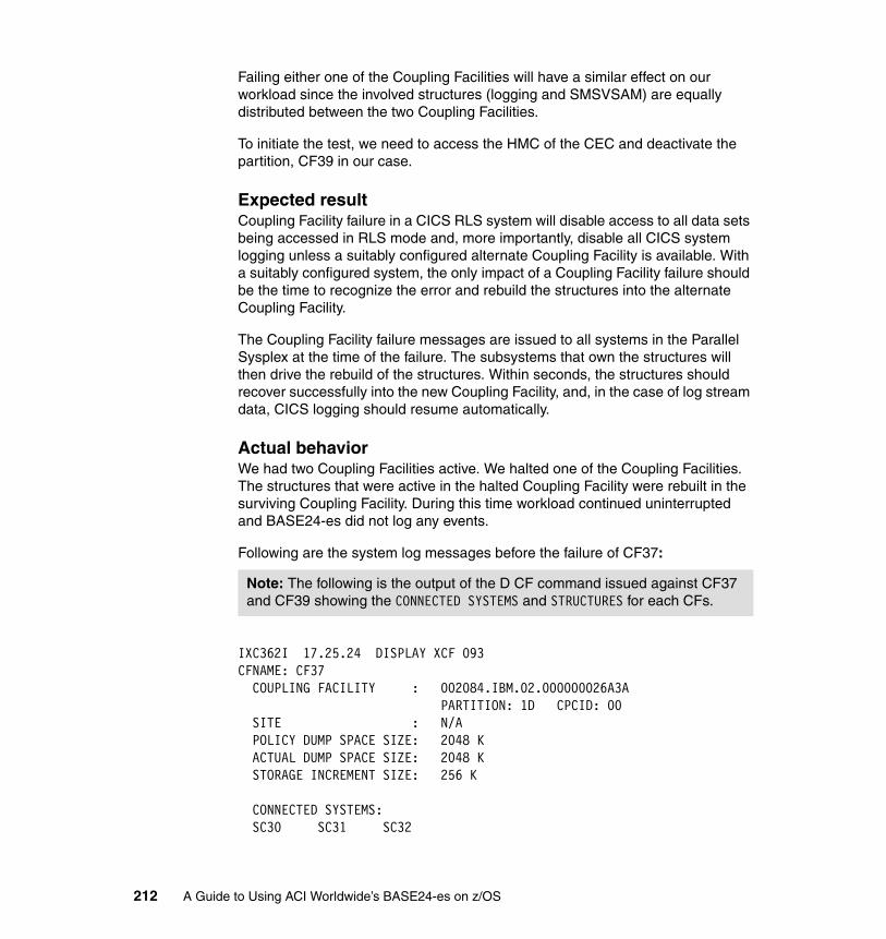
Failing either one of the Coupling Facilities will have a similar effect on our workload since the involved structures (logging and SMSVSAM) are equally distributed between the two Coupling Facilities.
To initiate the test, we need to access the HMC of the CEC and deactivate the partition, CF39 in our case.
Expected resultCoupling Facility failure in a CICS RLS system will disable access to all data sets being accessed in RLS mode and, more importantly, disable all CICS system logging unless a suitably configured alternate Coupling Facility is available. With a suitably configured system, the only impact of a Coupling Facility failure should be the time to recognize the error and rebuild the structures into the alternate Coupling Facility.
The Coupling Facility failure messages are issued to all systems in the Parallel Sysplex at the time of the failure. The subsystems that own the structures will then drive the rebuild of the structures. Within seconds, the structures should recover successfully into the new Coupling Facility, and, in the case of log stream data, CICS logging should resume automatically.
Actual behaviorWe had two Coupling Facilities active. We halted one of the Coupling Facilities. The structures that were active in the halted Coupling Facility were rebuilt in the surviving Coupling Facility. During this time workload continued uninterrupted and BASE24-es did not log any events.
Following are the system log messages before the failure of CF37:
IXC362I 17.25.24 DISPLAY XCF 093 CFNAME: CF37 COUPLING FACILITY : 002084.IBM.02.000000026A3A PARTITION: 1D CPCID: 00 SITE : N/A POLICY DUMP SPACE SIZE: 2048 K ACTUAL DUMP SPACE SIZE: 2048 K STORAGE INCREMENT SIZE: 256 K CONNECTED SYSTEMS: SC30 SC31 SC32
Note: The following is the output of the D CF command issued against CF37 and CF39 showing the CONNECTED SYSTEMS and STRUCTURES for each CFs.
212 A Guide to Using ACI Worldwide’s BASE24-es on z/OS

STRUCTURES: IGWLOCK00 ISGLOCK ISTGENERIC ISTMNPS IXC_DEFAULT_1 IXC_DEFAULT_4 LOG_DFHLOG_001 RLSCACHE01 SYSTEM_OPERLOG SYSZWLM_6A3A2084
IXC362I 17.25.55 DISPLAY XCF 248 CFNAME: CF39 COUPLING FACILITY : 002094.IBM.02.00000002991E PARTITION: 2F CPCID: 00 SITE : N/A POLICY DUMP SPACE SIZE: 2048 K ACTUAL DUMP SPACE SIZE: 2048 K STORAGE INCREMENT SIZE: 256 K CONNECTED SYSTEMS: SC30 SC31 SC32 STRUCTURES: IXC_DEFAULT_2 IXC_DEFAULT_3 LOG_DFHSHUNT_001 RLSCACHE02 SYSIGGCAS_ECS SYSTEM_LOGREC SYSZWLM_WORKUNIT SYSZWLM_991E2094
Following are the system log messages after failure:
4040000 SC30 2006144 17:29:49.24 00000090 IFB100E LOGREC LOG STREAM ERROR ON SYSTEM SC30 - RC=0008-0864 815 815 00000090 UNABLE TO WRITE TO LOG STREAM - LOG STREAM IS NOT AVAILABLE 815 00000090 LOG STREAM NAME: SYSPLEX.LOGREC.ALLRECS 815 00000090 STRUCTURE NAME: SYSTEM_LOGREC
CFNAME: CF37 COUPLING FACILITY : 002084.IBM.02.000000026A3A PARTITION: 1D CPCID: 00 SITE : N/A
Note: The following is the output of the D CF command issued against CF37 and CF39 after the failure, showing the CONNECTED SYSTEMS and STRUCTURES for each CFs.
Chapter 9. Achieving high availability on z/OS 213

POLICY DUMP SPACE SIZE: 2048 K ACTUAL DUMP SPACE SIZE: 2048 K STORAGE INCREMENT SIZE: 256 K CONNECTED SYSTEMS: SC30 SC31 SC32 STRUCTURES: IGWLOCK00 ISGLOCK ISTGENERIC ISTMNPS IXC_DEFAULT_1 IXC_DEFAULT_2 IXC_DEFAULT_3 IXC_DEFAULT_4 LOG_DFHLOG_001 LOG_DFHSHUNT_001 RLSCACHE01 RLSCACHE02 SYSIGGCAS_ECS SYSTEM_LOGREC SYSTEM_OPERLOG SYSZWLM_WORKUNIT SYSZWLM_6A3A2084 SYSZWLM_991E2094
Following are the system log messages after failure for CF37:
CFNAME: CF39 COUPLING FACILITY : 002094.IBM.02.00000002991E PARTITION: 2F CPCID: 00 SITE : N/A POLICY DUMP SPACE SIZE: 2048 K ACTUAL DUMP SPACE SIZE: 2048 K STORAGE INCREMENT SIZE: 256 K NO SYSTEMS ARE CONNECTED TO THIS COUPLING FACILITY STRUCTURES: IXC_DEFAULT_2(PND) IXC_DEFAULT_3(PND) LOG_DFHSHUNT_001(PND) RLSCACHE02(PND) SYSIGGCAS_ECS(PND) SYSTEM_LOGREC(PND) SYSZWLM_WORKUNIT(PND) SYSZWLM_991E2094(PND)
SolutionThe expected behavior was observed.
9.6 z/OS and relevant subsystems
The following scenarios highlight best practices regarding z/OS and the relevant subsystems:
� z/OS maintenance
Note: No systems are shown in the CONNECTED section of the message.
214 A Guide to Using ACI Worldwide’s BASE24-es on z/OS
� CF maintenance
9.6.1 z/OS maintenance - best practices
Objective and InjectionObjective of this test was to show that the workload from the simulator will continue to flow and execute successfully even when we are removing a z/OS system from the configuration.
To initiate the test, we will perform an orderly shutdown of all the subsystems running on one of the z/OS images (for example, SC32), by following a normal shutdown procedure. After the subsystems have been closed, we can deactivate the LPAR from the HMC (optional).
ConfigurationThe test will take place while the workload is running across the three systems: SC30, SC31, and SC32. One system, SC32 in our case, is going to be shut down to simulate a normal maintenance procedure.
Expected resultThere should be no impact to end users.
When the connection with the TOR is closed, the workload simulator will reconnect automatically after 5 seconds, using the same IP address. If the network has routing capability, this connection will be routed and established with the surviving TORs. In this case there will no loss from the client’s side.
If the network does not have routing capability, the driver will keep pinging the same IP address until the TOR is back on the same LPAR.
Actual behaviorThe procedure to maintain a z/OS system has been tested within IBM and documented in multiple sources. We do not consider this scenario to be specific to the BASE24-es application, and implicitly it is covered in 9.5.1, “Central Processor (CP) failure” on page 206.
9.6.2 CF maintenance - best practices
Objective and InjectionThe objective of this test was to verify that the workload from the simulator continues to flow and execute successfully when it is necessary to shut down a Coupling Facility for maintenance. A Coupling Facility might need to be removed
Chapter 9. Achieving high availability on z/OS 215

from a sysplex for maintenance, to have a new level of Coupling Facility control code installed, or to be replaced.
When such a situation occurs, you must remove any structures contained in the Coupling Facility before it is shut down and removed from the sysplex. We will demonstrate that it is possible to move all the structures from one Coupling Facility to the alternate one without interrupting the workload.
This scenario makes sense only if the installation is planning to have at least two Coupling Facilities in the configuration. With one Coupling Facility, some of the subsystems will not be able to operate.
ConfigurationFollowing is the configuration of the Coupling Facilities used for our scenarios:
CF37 contains the following structures:IGWLOCK00 ISGLOCK ISTGENERIC ISTMNPS IXC_DEFAULT_1 IXC_DEFAULT_4 LOG_DFHLOG_001 RLSCACHE01 SYSTEM_OPERLOGSYSZWLM_6A3A2084
CF39 contains the following structures:
IXC_DEFAULT_2 IXC_DEFAULT_3 LOG_DFHSHUNT_001RLSCACHE02 SYSIGGCAS_ECS SYSTEM_LOGREC SYSZWLM_WORKUNIT SYSZWLM_991E2094
Since the structures are equally distributed among the CFs, the procedure to apply maintenance would be similar for either one of the CFs. In our scenario, we use CF37.
The following procedure will remove CF37 from the sysplex:
1. Create a new CFRM policy that does the following (optional step):
– Deletes any reference to the Coupling Facility to be removed.
– Includes the name of the Coupling Facility where all structures are to be rebuilt in the preference list.
Use a name for the new CFRM policy that is different from the name of the original CFRM policy so that when Coupling Facility maintenance is complete, the original policy can be restored.
2. To determine the CHPIDs in use by the Coupling Facility to be removed, issue the following command on each system connected to the Coupling Facility: D CF,CFNAME=CF37
216 A Guide to Using ACI Worldwide’s BASE24-es on z/OS
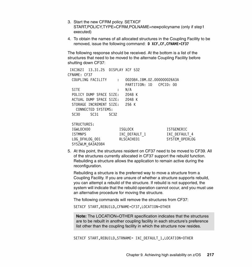
3. Start the new CFRM policy. SETXCF START,POLICY,TYPE=CFRM,POLNAME=newpolicyname (only if step1 executed)
4. To obtain the names of all allocated structures in the Coupling Facility to be removed, issue the following command: D XCF,CF,CFNAME=CF37
The following response should be received. At the bottom is a list of the structures that need to be moved to the alternate Coupling Facility before shutting down CF37:
IXC362I 13.31.25 DISPLAY XCF 532 CFNAME: CF37 COUPLING FACILITY : 002084.IBM.02.000000026A3A PARTITION: 1D CPCID: 00 SITE : N/A POLICY DUMP SPACE SIZE: 2048 K ACTUAL DUMP SPACE SIZE: 2048 K STORAGE INCREMENT SIZE: 256 K CONNECTED SYSTEMS: SC30 SC31 SC32 STRUCTURES: IGWLOCK00 ISGLOCK ISTGENERIC ISTMNPS IXC_DEFAULT_1 IXC_DEFAULT_4 LOG_DFHLOG_001 RLSCACHE01 SYSTEM_OPERLOG SYSZWLM_6A3A2084
5. At this point, the structures resident on CF37 need to be moved to CF39. All of the structures currently allocated in CF37 support the rebuild function. Rebuilding a structure allows the application to remain active during the reconfiguration.
Rebuilding a structure is the preferred way to move a structure from a Coupling Facility. If you are unsure of whether a structure supports rebuild, you can attempt a rebuild of the structure. If rebuild is not supported, the system will indicate that the rebuild operation cannot occur, and you must use an alternative procedure for moving the structure.
The following commands will remove the structures from CF37:
SETXCF START,REBUILD,CFNAME=CF37,LOCATION=OTHER
SETXCF START,REBUILD,STRNAME= IXC_DEFAULT_1,LOCATION=OTHER
Note: The LOCATION=OTHER specification indicates that the structures are to be rebuilt in another coupling facility in each structure's preference list other than the coupling facility in which the structure now resides.
Chapter 9. Achieving high availability on z/OS 217
SETXCF START,REBUILD,STRNAME= IXC_DEFAULT_4,LOCATION=OTHER
Configure all CHPIDs offline to the Coupling Facility that you are removing.
6. Power off the Coupling Facility. In our case, we will simple deactivate the CF LPAR. When the Coupling Facility is deactivated, any remaining structure data is lost.
Expected resultWe expect to see the rebuild messages for the structures allocated in CF37. After the moves are completed, there should be no structures left in CF37. We expect to see no variation, from a workload point of view. Within seconds, the structures should be successfully moved into the new Coupling Facility, and in the case of log stream data, CICS logging should resume automatically.
Actual behaviorThe maintenance procedure for a Coupling Facility has been tested within IBM and documented in multiple sources, for example, in Setting up a Sysplex. We do not consider this scenario to be specific to the BASE24-es application and it is implicitly covered in 9.5.3, “Coupling Facility (CF) failure” on page 211.
Note: The XCF signalling structures must be rebuilt one at a time. After all structures have been removed from CF37, it can be removed from the configuration for maintenance.
218 A Guide to Using ACI Worldwide’s BASE24-es on z/OS
Chapter 10. Conclusion
In the payment transaction industry, it is crucial to have an IT infrastructure that is designed and deployed with sufficient redundancy to support the uptime requirements of its users, because failures occur in hardware, system software, application software, and networks.
In this chapter, we summarize the high availability requirements of a payment transactions enterprise and reiterate how the BASE24-es installation on z/OS and the test scenarios described this redbook demonstrate the ability to achieve the highest level of availability. You can use these scenarios to verify correct product installation. We also present a minimum setup for high availability of BASE24-es on z/OS.
10
© Copyright IBM Corp. 2006. All rights reserved. 219
10.1 Summary
Failures in a payments environment are a highly visible customer service issue. The entire payments cycle must be conducted in near real-time. Outages at any point will negatively affect customer loyalty. A payments environment is an online business that must be up and running when customers expect the system to be there, and have the capacity to handle the heaviest workload.
In this environment, continuous availability from end to end is not just a server requirement, but a requirement for all components in the IT complex. The weakest link determines availability as perceived by customers.
Maintaining availability for ATM and POS networks has been characterized by predictable workloads for many years. Application changes have been few and the business model has been stable. A stable environment also requires comparatively few personnel to support it and only limited changes in their skill sets.
10.2 The payment environment requirements
The new-generation payments environment, however, will be characterized by higher levels of front-end and back-end integration. The ability to operate transparently across all channels, including home and mobile banking via the Internet, will be critical. This will mean not only that a range of new technologies must be accommodated, but also that workloads will become less predictable and more subject to unexpected peaks and fluctuations.
The cost of maintaining high availability is of great importance to the payments industry. The technical challenge facing this environment is how to modernize processes while at the same time radically reduce switching costs and minimize the risks of change.
In-house developed solutions account for more than half the systems in the total payments environment. These legacies, often old designed applications, consist of low-level programming languages which require a specialist staff to maintain. The design often consists of inflexible software that cannot be easily modified to keep pace with market changes.
BASE24-es uses modular design/object-orientated application development tools and scripting. The scripting component is based on open systems architecture and enables users to rapidly change specific authentication requirements on transactions from delivery channels. Benefits of this scripting flexibility are shorter response times to changing business needs, reduced risk,
220 A Guide to Using ACI Worldwide’s BASE24-es on z/OS
and improved customer loyalty. The enhanced configuration capability offers a high degree of flexibility to address individual service needs.
The BASE24-es program code stream is by and large generic for all platforms, so that the differences in the implementations on these platforms can be attributed largely to the Quality of Service (QoS) of the platforms themselves and their underlying basic software infrastructure.
IBM System z is designed for, and employed in, a broad range of business-critical roles. Mixed workload execution, as well as data and system management capabilities, are superior to any server counterparts. System z also implements functions such as logical partitioning and virtual Linux™ server hosting, and the workload management facilities are significantly better optimized for volatile Web transaction workloads than those of other servers.
System z, when deployed in a Parallel Sysplex cluster, offers continuous availability, an extraordinarily high-performance I/O handling capability, and near linear scalability for BASE24-es on z/OS. A Parallel Sysplex cluster can be engineered with no single point of failure by employing redundant I/O paths with transparent, dynamic switching, triple mirroring, highly-available networking, and automatic and transparent failure handling and restart capabilities.
10.2.1 Conclusions
Our BASE24-es installation on z/OS and the tests performed in the scenarios clearly demonstrate the ability to achieve the highest level of availability.
For this project, we tested numerous failure scenarios for availability on hardware, system software, and application software. The scenarios are described in detail in this redbook, and they can be used as reference for the verification of correct product installation. We used BASE24-es release 06.2 in a beta version, and achieved the expected behavior.
A payment transaction system is a highly specialized application. When moving an existing in-house developed application or EFT application from another platform, the staff who know and understand the application can apply their knowledge and experience to migrate the software to the mainframe platform.
Minimum configurationIn this section we list a minimum setup for high availability of BASE24-es on z/OS:
� Two LPARs distributed in a Parallel Sysplex cluster, one LPAR per CPC. Be sure your configuration has at least two Coupling Facilities.
Chapter 10. Conclusion 221
� On each LPAR, at least one Terminal Owning Region (TOR) running with at least two cloned Application Owning Regions (AORs).
� On each AOR, at least two BASE24-es Integrated Server tasks.
� CICSplex System Manager (CP/SM), together with BASE24-es workload management facilities, are used to provide the dynamic routing capability from each TOR to all the AORs.
� AORs accessing the VSAM files in Record Level Sharing (RLS) mode through the SMSVSAM address space. SMSVSAM will allocate the cache and lock structure to the Coupling Facilities available to the Parallel Sysplex cluster.
222 A Guide to Using ACI Worldwide’s BASE24-es on z/OS
Glossary
Application-Owning Region (AOR). In multiregion operation (MRO) or intersystem communication (ISC), a CICS address space whose primary purpose is to manage application programs. It receives transaction routed requests from a terminal-owning region (TOR). See also terminal-owning region, file-owning region.
Application Programming Interface (API). The interface by which an application program accesses operating system and other services. An API is defined at source code level and provides a level of abstraction between the application and the kernel (or other privileged utilities) to ensure the portability of the code.
Automatic Restart Manager (ARM). A z/OS recovery function that can automatically restart batch jobs and started tasks after they or the system on which they are running terminate unexpectedly.
Asynchronous request. A request that is issued without immediately awaiting a response. If a response is expected, the issuing application typically starts a timer and performs other work until a response is received or a timer expiration occurs.
Coordinating Address Space (CAS). The function that sets up the CICSPlex SM component topology and that supports the MVS/TSO ISPF graphic user interface to CICSPlex SM. CAS is used in CMAS-to-CMAS links.
Coupling Facility (CF). A special LPAR that provides high-speed caching, list processing, and locking functions in Parallel Sysplex.
CFRM policy. The allocation rules for a Coupling Facility structure that are declared by a z/OS administrator.
© Copyright IBM Corp. 2006. All rights reserved.
Coupling Facility Resource Management (CFRM). A set of definitions for the use of a Coupling Facility. CFRM provides the services to manage Coupling Facility resources in a sysplex.
CICS Complex (CICSPlex). A collection of related and connected CICS regions, which helps to address the efficiencies in having multiple, full-function CICS systems processing a single OLTP workload.
Client (TCP/IP). A TCP/IP client establishes a connection, typically using the connect() sockets API call. In the world of short-lived sockets, the client usually also speaks first, sending the initial application-level request, receiving a response, and disconnecting. In the world of long-lived sockets common in the world of financial online transactions, it is common for a TCP/IP client to be an application-level server. The BASE24-es TCP/IP Client Communications Handler is a TCP/IP client. See Server, Listener.
CICSPlex SM Address Space (CMAS). A CICSPlex SM component that is responsible for managing CICSplexes. A CMAS provides the single-system image for a CICSplex by serving as the interface to other CICSplexes and external programs. There must be at least one CMAS in each MVS image on which you are running CICSPlex SM. A single CMAS can manage CICS systems within one or more CICSplexes.
Central Processor (CP). The part of the computer that contains the sequencing and processing facilities for instruction execution, initial program load, and other machine operations.
223

CICSPlex System Manager (CP/SM). A system-management tool that enables you to manage multiple CICS systems as though they were one. CICSPlex SM can manage independent, full-function CICS systems running on one or more connected central processor complexes (CPCs) just as easily as it can manage multiple, interconnected CICS systems functioning as a CICSplex, also on one or more connected CPCs.
Central Processor Complex (CPC). In a z/OS or OS/390 environment, a physical collection of hardware that consists of main storage, one or more Central Processors, timers, and channels.
Data Access layer (DAL). A BASE24-es System Interface Services component that provides the BASE24-es application with a common API to access various databases and file systems, such as VSAM.
Direct Access Storage Device (DASD). A device that allows storage to be directly accessed, such as a disk drive.
Dynamic Destination Map File (DDMF). A routing configuration file used by the BASE24-es System Interface Services Message Delivery Service to route asynchronous messages.
Distributed Program Link (DPL). A function of CICS intersystem communication that enables an application program to ship LINK requests to another application program on a different instance of CICS.
Electronic Software Distribution (ESD).
File-Owning Region (FOR). A CICS address space whose primary purpose is to manage files and databases.Also known as data-owning region.
Hierarchical File System (HFS). A system for organizing files in a hierarchy, as in a UNIX system. z/OS UNIX System Services files are organized in an HFS.
Hardware Security Module (HSM). A secure Crypotographic facility for card holder PIN transaction, verification and message authentication.
Listener (TCP/IP). A TCP/IP listener waits for a connection, typically using the bind(), listen() and accept() sockets API calls. A TCP/IP server typically does not perform other productive work, handing the established socket off to another task to accept requests and send responses while the listener awaits more connections. The IBM-provided CSKL transaction is a TCP/IP listener, which hands the established socket off to another task such as the BASE24-es SIDC database server. See Client, Server.
Logical partition (LPAR). A subset of a single system that contains resources (processors, memory, and input/output devices). A logical partition operates as an independent system. If hardware requirements are met, multiple logical partitions can exist within a system.
Managed Address Spaces (MAS). A CICS system that is being managed by CICSPlex SM.
Multiregion Operation (MRO). Communication between CICS systems in the same processor without the use of SNA network facilities. This allows several CICS systems in different regions to communicate with each other, and to share resources such as files, terminals, temporary storage, and so on.
Not-on-us card. A card which was not issued by the financial institution and which is usually routed to a public card network for authorization. See on-us.
Offline authorization. An authorization type wherein BASE24-es is configured to authorize on-us transactions using its own database and scripts. See on-us, online, online/offline.
Online Analytical Processing (OLAP).
224 A Guide to Using ACI Worldwide’s BASE24-es on z/OS

Online Transaction Processing (OLTP). A type of interactive application in which requests submitted by users are processed as soon as they are received. Results are returned to the requester in a relatively short period of time.
Online authorization. An authorization type wherein BASE24-es is configured to route on-us authorization requests to a back-end host authorization system. If the back-end system is unavailable, requests may be configured to be routed to an alternate authorizer. See on-us, offline, online/offline.
Online/offline authorization. An authorization type wherein BASE24-es is configured to route on-us authorization requests to a back-end host authorization system. If the back-end system is unavailable, requests may be configured to be routed to an alternate authorizer. If no alternate authorizer is configured, or if the alternate is unavailable, BASE24-es may stand in and perform authorization using its own database and scripts. See on-us, offline, online/offline.
On-us card. A card that is issued by the financial institution and which is usually to be authorized locally. See not on-us.
Record Level Sharing (RLS). See VSAM record-level sharing.
System Authorization Facility (SAF). A z/OS facility through with programs communication with an external security manager such as RACF.
Static Destination Map File (SDMF). A configuration file used by the BASE24-es System Interface Services Message Delivery Service to define attributes of various endpoints.
Server (TCP/IP). A TCP/IP server waits for a connection, typically using the bind(), listen() and accept() sockets API calls. A TCP/IP server typically also performs productive work, accepting requests and sending responses. In the world of short-lived sockets, the client usually also speaks first. The server receives a request, sends a response, and awaits either a new request or a client disconnect. In the world of long-lived sockets common in the world of financial online transactions, the TCP/IP server may be an application-level client, and send the initial request. The BASE24-es TCP/IP Server Communications Handler is a TCP/IP server. See Client, Listener.
System Interface Services (SIS). The group of BASE24-es components that provide a platform-dependent implementation of a platform-independent system services API, allowing the rest of the BASE24-es code to run without modification on various hardware and middleware configurations. SIS includes DAL, Time, Timer, Message Delivery, and similar services.
System Initialization Table (SIT). A table containing parameters used by CICS upon startup.
SMSVSAM. The name of the VSAM server that provides VSAM record-level sharing (RLS). See also VSAM record-level sharing.
Synchronous Destination Map File (SYDMF). A routing configuration file used by the BASE24-es System Interface Services Message Delivery Service to route synchronous messages.
Synchronous request. A request that is issued followed by an immediate wait for response. Generally acceptable only for lower-latency, highly-reliable servers.
SYStem comPLEX (sysplex). A set of z/OS systems communicating and cooperating with each other, through certain multisystem hardware components and software services, in order to process customer workloads.
Glossary 225

Transient Data Queue (TDQ). A common abbreviation for the CICS management module and its associated functions for intra-partition and extra-partition data queues.
Terminal-Owning Region (TOR). A CICS region which owns most or all of the terminals defined locally. See also application-owning region, data-owning region.
Temporary Storage Queue (TSQ). A queue of data items which can be read and reread, in any sequence. The queue is created by a task, and persists until the same task, or a another task deletes it.
Virtual Storage Access Method (VSAM). An access method for direct or sequential processing of fixed-length and varying-length records on direct access devices. The records in a VSAM data set or file can be organized in logical sequence by a key field (key sequence), in the physical sequence in which they are written on the data set or file (entry sequence), or by relative record number.
VSAM Record-Level Sharing (VSAM RLS). An extension to the Virtual Storage Access Method (VSAM) that provides direct record-level sharing of VSAM data sets from multiple address spaces across multiple systems. Record-level sharing uses the z/OS Coupling Facility (CF) to provide cross-system locking, local buffer invalidation, and cross-system data caching.
Virtual Telecommunications Access Method (VTAM). An IBM licensed program that controls communication and the flow of data in an SNA network. It provides single-domain, multiple-domain, and interconnected network capability.
Workload Manager (WLM). A z/OS construct that provides services to manage workload distribution, balance workload, and distribute resources.
226 A Guide to Using ACI Worldwide’s BASE24-es on z/OS
Related publications
The publications listed in this section are considered particularly suitable for a more detailed discussion of the topics covered in this redbook.
IBM RedbooksFor information about ordering these publications, see “How to get IBM Redbooks” on page 227. Note that some of the documents referenced here may be available in softcopy only.
� IBM System z9 and zSeries Connectivity Handbook, SG24-5444
� GDPS Family - An Introduction to Concepts and Capabilities, SG24-6374
Other publicationsThese publications are also relevant as further information sources:
� DTR BASE24-es IBM CICSplex Installation Guide
� Setting up a Sysplex, SA22-7625
Online resourcesThese Web sites and URLs are also relevant as further information sources:
� z/OS UNIX ported tools
http://www.ibm.com/servers/eserver/zseries/zos/unix/bpxalty1.html
How to get IBM RedbooksYou can search for, view, or download Redbooks, Redpapers, Hints and Tips, draft publications and Additional materials, as well as order hardcopy Redbooks or CD-ROMs, at this Web site:
ibm.com/redbooks
© Copyright IBM Corp. 2006. All rights reserved. 227

Help from IBMIBM Support and downloads
ibm.com/support
IBM Global Services
ibm.com/services
228 A Guide to Using ACI Worldwide’s BASE24-es on z/OS
Index
AACI application 17ACI Payments Framework 21acquirer 53, 69–70, 77, 81, 85, 87–88, 139, 162, 164–165, 195acquirer route profile 69–70, 86active AOR 165activity keypoint 176, 179Adaptors 18ALLOWAUTOALT 177, 179, 181–182AOR
architecture 56AOR column 173–174AOR failure 106AOR Message
Delivery program 56Delivery transaction XDYR 54
AOR Scope 142, 171, 173AORs 104–105, 107, 116, 118–119, 121, 124, 128, 161, 165–166, 175, 193–194, 202, 210, 222API 48, 142API flag 142, 171, 173Appl name 171–173application code 7, 19
same set 19Application Key 141, 169, 171–173Application Owning Regions (AOR) 104–107, 160, 162–163, 165–166, 168, 170–171, 173, 176, 184, 190, 192, 194, 198, 203, 222associated TDQ
XMLS server 92ATM processing 4authentication 15authorization 15
level 15Authorization Script
OLTP Table 71Table 71
Automated Teller Machine (ATM) 1–6, 10, 89, 101Automatic Restart Manager (ARM) 32, 103, 106, 128, 162–164, 166–167, 209autonomic 9available AOR 48, 54, 162–163
© Copyright IBM Corp. 2006. All rights reserved.
BBanknet Interface 71BASE24-es
architecture 17flexible infrastructure 16introduction 14reporting 17software components 18VTAM support 35
BASE24-es application 21, 45, 120, 124, 126–127, 150
alternate routing capabilities 202maximum availability 124
BASE24-es customer 119–120BASE24-es Dynamic
Destination entry 141Destination Map 139–140Transaction 141, 146
BASE24-es FilePartitioning 150, 154
BASE24-es file 129, 146–151, 154BASE24-es Integrated Server 43, 47, 56–57, 59–62, 92, 94, 140–141, 185, 187, 194, 198
multiple concurrent instances 43process 140special instance 92task 222transaction 140
BASE24-es internal header 54, 59, 68only messages 60
BASE24-es Metadata configurationCONFCSV 151, 155
BASE24-es metadata configurationfile 185file CONFCSV 147–148
BASE24-es product 13–14, 128BASE24-es solution 17, 101BASE24-es system 19, 55, 68, 101, 114, 189, 191, 194
CICS transaction 55, 68financial integrity 194routable endpoint 55, 68
BASE24-es TaskMonitor 52, 54, 56–57, 106, 190, 192, 194
229
BASE24-es TCP/IPclient 51, 90communications handler 89, 91Control File 138process 138–140server 53, 89–90task 139
BASE24-es transaction 48, 89BASE24-es workload management
facility 222file 55–56, 68
Business Application Services (BAS) 133business components 18business-critical application 31, 113
CCapacity Upgrade on Demand 10card support 17CEMT command 145–146Central Processor (CP) 10, 108, 206Central Processor Complex (CPC) 108–109, 115, 117, 119, 124, 206, 209CF
failure-isolated 109CF failure 110
As stated 108–112failed CF support recovery 110
CF maintenance 110, 112CFRM policy 112, 127, 177, 216–217CICS Automatic 162–163CICS facility 55, 68CICS Link 63, 88, 141, 204CICS program 44, 46, 198CICS region 45, 91, 100, 107, 126–127, 140, 167–168, 184–185, 209–210
affinity 69initialization 57, 69server class 45start 140
CICS statistic 96–97CICS transaction 46, 60, 139–140
id 191, 193, 195XDYR 140
CICS Transient Data Queues 43CICSPlex 48–49, 94, 106–107CICSplex 126, 132–133CICSplex System Management (CPSM) 132–134CICSplex System Manager 44
CICSplex System Manager (CPSM) 124, 134, 141, 222CMAS 160–161Common Operating Environment (COE) 10Communication Server 126Communications Server 29Complementary Metal Oxide Semiconductor (CMOS) 28computing model 25
centralized 25computing models 25consumer authentication 14Controlled Access Protection Profile (CAPP) 10corresponding entry 139, 150Coupling Facility (CF) 8, 96–97, 107–108, 124, 176–177, 179, 181, 183, 210–216, 218, 221
allocated structures 217logging information 210
CP failure (CF) 206–207, 212, 215–216, 218CRM 16Cross Coupling Facility (XCF) 27Cryptographic 63cryptographic considerations 61Cryptographic Coprocessor 29Cryptography, provided by System z 28CSKL 52customer relationship management (CRM) 16
DData Access Layer (DAL) 19, 130data proximity 26, 38data set name (DSN) 145data source 71, 73–75, 77, 81, 83, 85, 87, 150, 153, 184, 188–189, 206default seq 171, 173deployment
single-region 46three-tier 48two-tier 47
DFSMS 30Diebold Number Table (DNT) 74Direct Access Storage Device (DASD) 113, 150disaster recovery 32Distributed Program Link (DPL) 64Domain Name Services (DNS) 29Dynamic Destination Map File (DDMF) 134dynamic routing
capability 124, 222
230 A Guide to Using ACI Worldwide’s BASE24-es on z/OS

program 141transaction XDYR 48
Dynamic Transaction 106, 141, 144, 146, 170, 172dynamic transaction 48
Eeconomies of scale 37Electronic Software Distribution (ESD) 129Encryption PIN Pad
public key information 73Encryption PIN Pad (EPP) 73end-to-end protocol 42, 106, 160end-to-end recovery 162, 164, 194e-payment system 99, 116Error Table 188–189, 205EuronetThe Exchange 4event message 75, 144, 185, 188EXEC CICS
Link 204READQ TS 185
external authorization 63data communication 65distributed link 64WebSphere MQ 67
external authorization system 63–65, 67–68AOR 63BASE24-es ix, 41–55, 57–65, 67–69, 87–93, 95–96excessive latency 66One option 63
external authorization system (EAS) 63external endpoint 46, 66
Ffault tolerance 3, 7, 9, 160files
Acquirer_Issuer_Relation 69Acquirer_Issuer_Relation_OLTP 70Acquirer_Route_Profile 70Acquirer_Txn_Allowed 70Acquirer_Txn_Allowed_OLTP 70Action_Code_Extrn_to_Intrn 70Action_Code_Extrn_to_Intrn_OLTP 70Action_Code_Intrn_to_Extrn 71Action_Code_Intrn_to_Extrn_OLTP 71Active_Script_Statistics 71Admin_Card 71Audit_Store_and_Forward 71
Audit_Store_and_Forward_Config 71Authorization_Script 71Authorization_Script_OLTP 71Banknet_Configuration 71Banknet_Configuration_OLTP 72Banknet_Group_Timers 72Banknet_Institution_Id 72Banknet_Institution_Id_OLTP 72Banknet_Merchant_Program 72Banknet_Merchant_Program_OLTP 72Card 72Card File 69Card_Account 72Card_Verification 72Card_Verification_OLTP 72Chan_Profile_Instrm_Typ_Rel_OLTP 72Chan_Profile_Instrm_Typ_Relation 72Channel_Instrm_Type_Relation 73Channel_Public_Key_Security 73Channel_Security 73Compiler_Message 73Context 73Context File 69Context_Configuration 73Context_Configuration_OLTP 73Contingency_Interface 73Contingency_Interface_OLTP 73Currency_Conversion_Rate 74Currency_Conversion_Rate_OLTP 74definition 55Diebold_Number_Table 74DTR Control file 56, 69Dynamic Destination Map File 55, 68Event Log 56, 68Socket Records file 56Static Destination Map File 55, 68Synchronous Destination Map File 55, 68TCP/IP Configuration File 56Terminal Configuration File 55
financial institution 1, 3–4, 14financial transaction 3, 35, 141, 144, 149, 151–154, 171–172
dynamic routing 141foundation components 18
GGDPS 33GDPS modes 33
Index 231

GDPS/PPRC 33GDPS/XRC 33Geographically Dispersed Parallel Sysplex (GDPS) 33–34
Hhandshake trn 171, 173Hardware Management
Console 113Hardware Security Module (HSM) 61–63hashing algorithm 147, 153Hierarchical File System (HFS) 129HiperSockets 33host station 134, 141host-acquired transaction 87, 89
II/O capacity 95, 97I/O device 37IGWLOCK00 127, 174, 176–177, 179, 181–182, 211, 213–214, 216–217IMT Interface 76industry 2instrument type 72, 77, 81Integrated Server 57Integrated Server (IS) 44, 55, 99–101, 103–113, 115–120, 138–140, 146, 186–187, 204Integrated Servers 45Intelligent Resource Director (IRD) 31IP Client
task 189, 191, 193IP client 51–53, 61–62, 87, 89, 94, 171
failure 186, 189–191, 193process 163–164, 175queue 191recovery 191, 193
IP handler 44, 46, 52, 54, 66–67, 94, 105, 162–163, 167, 195
symbolic name 52, 54IP process 167, 191, 193IP Server
failure 160, 163, 186, 191failure scenario 192process 54, 164, 167task 191
IP tunnel 29issuer route profile 69–70, 78, 83
JJournal file 79, 95, 147, 152–153
storage capacity 79journal profile 78, 80, 153
LLanguage Environment (LE) 126logical file 147, 150, 152Long-running task 44, 56–58LPAR 27, 105, 108, 113, 115–116, 118–119, 124, 128, 221LPARs 27
Mmainframe
history 24member bank 7Message Deliver Program 57message queuing 42message queuing (MQ) 43–44, 55, 59–60, 67–68message type
and/or transaction code 79–80combination 78
MRO 44Multiple Image Facility (MIF) 109multiple LPARs 109, 115, 118–120Multiple Region Operations (MRO) 47–49, 94multiple TCP/IP
Client 94Server 94
Nname suffix 150–151, 154–155Network Control Program (NCP) 35Non-recoverable TDQs 45NOTRECOVABL 168
Ooffload processing 25OLTP table 70–73, 76–78, 80, 82, 86Online Transaction Processing
only table 70, 73, 76–78, 80–83, 86Online Transaction Processing (OLTP) 44, 52, 69–73, 75, 77–79, 81–82, 84, 86, 147, 160, 184On-us transaction 79, 87, 89openness 36Operating System 18, 24–25, 108, 129
232 A Guide to Using ACI Worldwide’s BASE24-es on z/OS
out-of-balance condition 162–163, 165, 195
Ppacket filtering 29Parallel Sysplex 8, 10–11, 24, 27, 31–34, 39, 95, 107–109, 112, 124, 126–127, 212
early days 109multiple CICS regions 126Other CICS applications 107z/OS system images 107
Peripheral Component Interface Cryptographic Co-processor (PCICC) 29Personal Account Number (PAN) 151–152Personal Identification Number (PIN) 16, 88platform-specific components 18Point-of-Sale (POS) 2–5, 7, 53, 76, 89POS device 5, 89POS network 220Processing Code
OLTP table 76table 76
processing code 69–70, 76, 79, 85first two characters 69–70
properly configured (PC) 128–129
QQuality of Service (QOS) 221
Rreal world
end-to-end recoverability 190, 193interface 162, 164–165, 195
Record Level Sharing (RLS) 43, 48, 56, 124, 126–127, 222Redbooks Web site 227
Contact us xiiRedundant I/O 7regional network 5relevant subsystem 159, 214reliability 3
requirements 2remote endpoint 45, 51–53, 56, 59, 94Resource Access Control Facility (RACF) 28Resource Recovery Services 32Resource Recovery Services (RRS) 32, 35Resource sharing 26–27response time 156
RLS 43RLS access 107, 175–176RLS mode 107, 212routable endpoint 68, 94Routing Region
IP client 171routing region 47, 134, 142, 144, 146, 161–162, 164, 167, 171
CICS APPLIDs 142host simulators 134
RSTR transaction 130–131
SScalability consideration 41, 94scale in 33scale out 33SDSF 30secondary destination 101–102security 27
accountability 28authentication 28Communications Server 29cryptographic 28
Security, provided by z/OS 29server class 45, 57server resource 10Service Name 134, 138–141setxcf Start 110, 113SHaring Control Data Sets (SHCDS) 107Single CPC 117, 119Single LPAR 116single point 8–9, 16, 32, 107, 109, 111–113, 116–117, 119–121, 221
parallel processing environment 8single region
CICS solution 127CSD 133installation 132
single-region deployment 46SMP/E 30SMSVSAM 44, 222SMSVSAM address space 107, 124SNA LU 54sockets API 94SPDH request 84
transaction code 85Store_and_Forward (SAF) 71, 85, 95surcharge datasource 85
Index 233
Synchronous Destination Map File (SYDMF) 134, 202SYSPLEX COMMPLEX 211Sysplex Distributor 27, 31, 101, 124, 163System Authorization Facility (SAF) 28System Automation 30System Initialization Table (SIT) 130System Integration Services (SIS) 129System Interface Service (SIS) 51, 138, 200–201, 204System Interface Services 42System Management Facility (SMF) 28System z ix, 7, 9, 23–24, 27–28, 30–35, 37, 39, 41, 44
BASE24-es physical architecture 44hardware 32, 39hardware platform 7machine 32platform 37processor 126server 7value 7
TTable name 151–153, 155–156target region 47, 141, 144
CICS APPLIDs 142TCP port 53TCP/IP Client 61
connection 103TCP/IP client 51–52, 101, 139–140, 160–161
and/or server 139process 139
TCP/IP communications handlers 45TCP/IP communications stack 43TCP/IP network 29TCP/IP protocol 34TCP/IP server 52–53, 140, 160, 163, 167
symbolic name 53type 139
TCP/IP service 91, 133TCP/IP stack 29TDQ 46, 48, 55, 57–60, 62, 66–67, 92–93, 106
non recoverable 45Temporary Storage Queue (TSQ) 61–63Terminal Owning Region 50Terminal Owning Region (TOR) 101, 124, 128, 222that originated the request (TOR) 101, 103–106,
116, 118–119Three-tier deployment 48Tivoli Enterprise Console 59Tivoli Workload Scheduler (TWS) 30, 36TOR
architecture 50TOR architecture 50TOR maintenance 160TOR region 161, 163TOR Scope 142, 171TORs 47–48, 50, 94, 101–104, 106, 116, 118–119, 121, 163, 165, 168, 194, 210, 215Total Cost
of Acquisition 37of Ownership 37–38
total cost 36Total Cost of Acquisition (TCA) 37Total Cost of Ownership (TCO) 37transaction
acquisition 7authentication 7categories 3
transaction code 69–70, 76, 79, 84text description 85
transaction manager 43transaction processing 15transactions
routing 14transactions per second (TPS) 97two-tier deployment 47
UUnified Modeling Language (UML) 21Unplanned event 100Usage file 95, 147–148, 154–156user interface 17, 19–20, 90, 92, 124, 126, 129, 131–132, 134–135
Vvirtual IP 101, 103Virtual Private Networks (VPN) 29Virtual Telecommunications Access Method (VTAM) 43virtualization 30VISA DPS 124, 129Visa PVV 87VSAM data 107–108VSAM file 107, 120, 124, 127, 146–148, 151, 154,
234 A Guide to Using ACI Worldwide’s BASE24-es on z/OS

222RLS access 107
VSAM with Record Level Sharing 43VTAM Reader/Writer 54–55, 89VTAM reader/writer
call 55CICS transaction 55program 54, 88task 89transaction 54
WWebSphere MQ 43, 55, 59–60, 67–68workload balancing 11workload driver 146, 148, 162, 164, 166–167, 171, 175, 184–187, 190, 192–194, 203–204, 210
transactions flow 186, 204Workload Management 48Workload Manager (WLM) 31
XXCF GRPNAME 183XDYR transaction 66XMLS TDQ 93
Zz/OS operating system
IBM System z hardware 44z/OS strengths 24z/OS value 23, 38zAAP 38zIIP 38zSeries Application Assist Processor (ZAAP) 10
Index 235

236 A Guide to Using ACI Worldwide’s BASE24-es on z/OS

(0.2”spine)0.17”<
->0.473”
90<->
249 pages
A Guide to Using ACI Worldw
ide’s BASE24-es on z/OS


®
SG24-7268-00 ISBN 073849593X
INTERNATIONAL TECHNICALSUPPORTORGANIZATION
BUILDING TECHNICALINFORMATION BASED ONPRACTICAL EXPERIENCE
IBM Redbooks are developed by the IBM International Technical Support Organization. Experts from IBM, Customers and Partners from around the world create timely technical information based on realistic scenarios. Specific recommendations are provided to help you implement IT solutions more effectively in your environment.
For more information:ibm.com/redbooks
A Guide to UsingACI Worldwide’s BASE24-es on z/OSSet up and use BASE24-es on z/OS
High availability scenarios
Configure for highest availability
In this IBM Redbook we explain how to use the ACI BASE24-es product on z/OS. BASE24-es is a payment engine utilized by the financial payments industry. Failure in a financial payments environment is a high-visibility customer service issue, and outages at any level have debilitating effects on customer loyalty. The entire payments cycle must be conducted in near real-time. In such an environment, high availability is a mission-critical requirement. We demonstrate how you can achieve a high availability configuration for BASE24-es on z/OS. We begin by outlining the requirements of a payments system, and then introduce the structure and functionality offered by the BASE24-es product. We describe the strengths and abilities of System z and z/OS, and explain the technical and physical architecture of BASE24-es on z/OS. We guide you in designing a system layout and in installing, tailoring, and configuring your workload on z/OS. Finally, we detail the numerous failure scenarios that we tested in order to verify the robustness of the solution. These scenarios were carefully selected in areas such as data environment, CICS/CICSplex, the BASE24-es application, and hardware. Communication was handled by ATM and POS device simulators and a Visa network simulator. Note that the information in this redbook is specific to BASE24-es release 06.2 and is subject to change in subsequent releases of the product.
Back cover