Embed Size (px)
Citation preview
Building a Basic Crate 2.0 A Guide for FRC Teams
Team 246
Overclocked
Boston University
Boston University Academy

1.1 Purpose of This Document
F.I.R.S.T. Robotics Competition teams need to ship their robot to and from
competition. Strict rules surrounding shipping and complications such as
reusability, assembly and weight provide a challenge to each team. However,
this is a challenge that each team faces equally and, unlike the game, is nearly
unchanging from year to year.
Special thanks to Richard Graft who originally designed this crate as a
donation to Team 1020. However, he, Team 246, Boston University and Boston
University Academy are not responsible for those using this design or any
loss/damage incurred as a result of the use of the crate designed within. This
design is offered in the spirit of Gracious Professionalism to aid teams, especially
rookies, in building an inexpensive, easy to maintain and tool-less crate (once
constructed). Support may be provided to those using this guide, but is of course
not guaranteed.
That said, if you have suggestions to improve this guide, please write us
at [email protected]. Thanks, and enjoy!

2.1 Materials Needed:
Quantity Item
4 3/8” Standard Plywood Sheet
(4’ x 8’)
1 ½” Standard Plywood Sheet
(4’ x 8’)
1 4”x4”x8’ Standard Lumber
6 2”x2”x12’ Standard Lumber
~50 ¼” 20 (“Quarter Twenty”) Carriage Bolts
at 4” length
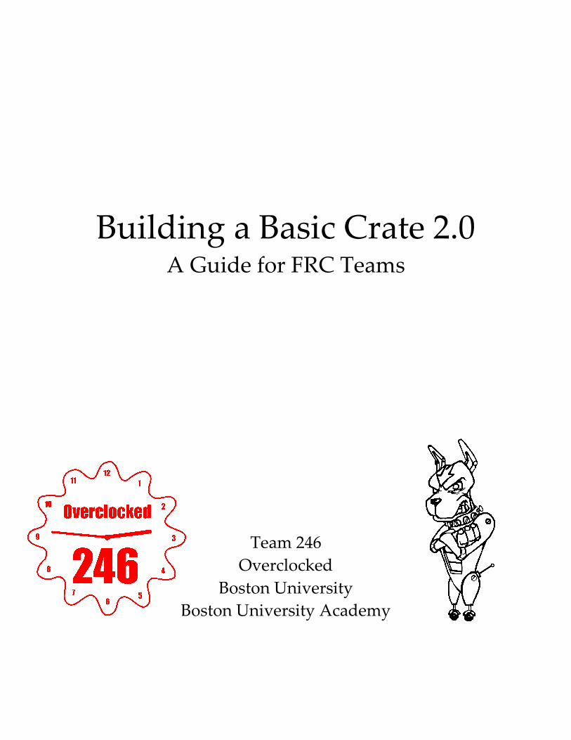
~50 ¼” 20 Wing Nuts
2 Pound box of standard deck screws
(1 ¼” length)
1 Pound box of standard deck screws
(2 1/2” length)
1 Roll of Clear Stretch Wrap (Stretch Film)
Notes about materials:
• Wing nuts are necessary to make crating/uncrating tool-less; use standard
hex nuts if you intend to use power-tools instead.
• Deck screws can be of a slightly different length, but not much since they
would protrude through or split the lumber.
• The thickness of the plywood is negotiable except that if you build using
all ½” plywood, your crate will likely be overweight. This will usually
cost you more than $100 each time you go to a competition. This is a
drayage cost, not shipping, so you cannot get around it with the free
FedEx shipping.

• You will also need packaging materials to prop up, pad and strap down
the robot within the crate. This is not covered by this crate design, though
there is plenty of space left within the inner dimensions for packaging.
We recommend using stiff foam (not Styrofoam) and cutting it to fit the
corners of your robot.
2.2 Tools Needed
Table Saw/Jig Saw/Circular Saw (only one of the three)
Power Drill
¼” Drill Bit
Phillips Screw Driver Bit
Hammer/Mallet

3.1 Plywood Pieces
Both piece A (called the Narrow Side) and B (called the Wide Side) are
made from 3/8” plywood. Piece C (called the Base and Top) is made from ½”
plywood. You need to make two of each of these three pieces. It’s not
important that they are flat, though you should take care to make them close to
the proper dimensions with squared edges.
Measure and cut the pieces using the table saw/jig saw/circular saw. You
won’t cut the pieces perfectly, so it’s best to try to make them a little smaller
rather than a little bigger. The dimensions and letters for the 3 pieces are below.
Again, you need two of each lettered piece.
64”
40.5”
44”
64”
46”
A B
C
46”

3.2 Lumber Pieces
Pieces D though G are made out of the 2” x 2” lumber and H is made out
of the 4” x 4” lumber. It is best if these pieces are slightly shorter than slightly
longer. However, you should take your time and try making these pieces nearly
perfect in length with square cuts and little or no bows in the wood.
Measure and cut the pieces using the table saw/jig saw/circular saw. You
will need multiples of each pieces – the quantities of each are indicated below the
diagrams below.
D E F G H
37.5” 40.5” 46” 61”
4 4
2
46”
4
2

4.1 Assembly
First you will attach the 5 2x2 pieces for side A to each other (pieces D, E
and G). Lay the pieces down as indicated on the diagram below (the D pieces
should be centered along the length of the G pieces). At each joint you will join
the two pieces with a single deck screw. To prevent splitting, you should drill a
pilot hole (use a 1/8” drill bit to make a hole where the screw will go). The red
arrows on the diagram below indicate the location and direction of these deck
screws.
Once you have the lumber frames for the A sides assembled, lie them
down and place the A plywood pieces over them. Use deck screws to attach the
plywood to the 2x2 lumber frames. You should put one screw at each corner and
then one about every 18” along the length of the 2x2 lumber pieces. You may
need to drill pilot holes for this step as well.
A G G
G G
E
E
D
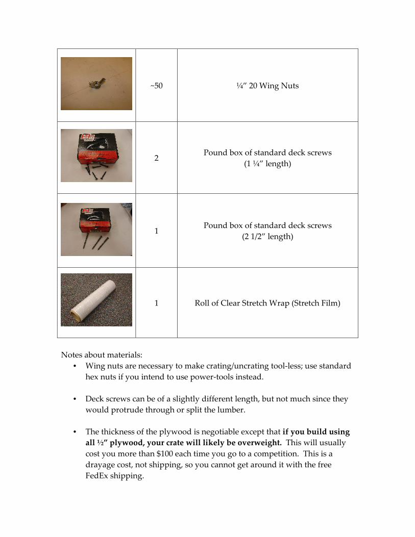
For the B sides, apply the same basic steps as the last paragraph using the
F 2x2 lumber pieces. As you can see, these pieces don’t form a frame, so you
don’t need to assemble the 2x2 pieces first.
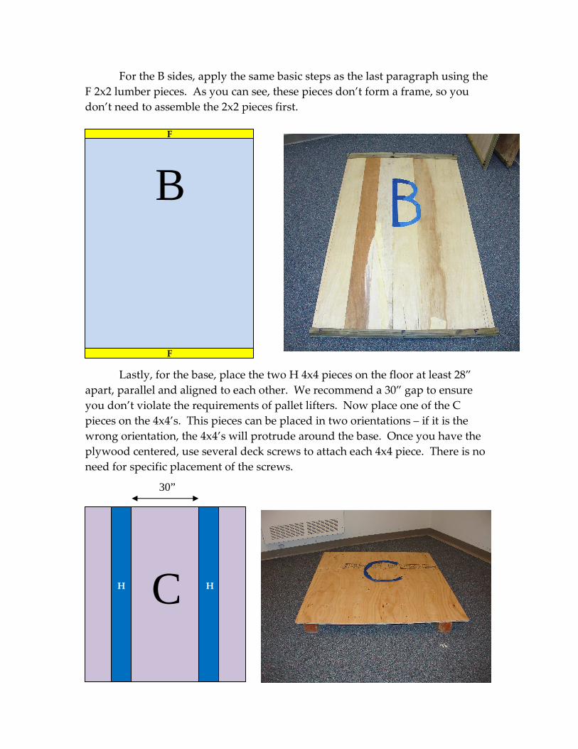
Lastly, for the base, place the two H 4x4 pieces on the floor at least 28”
apart, parallel and aligned to each other. We recommend a 30” gap to ensure
you don’t violate the requirements of pallet lifters. Now place one of the C
pieces on the 4x4’s. This pieces can be placed in two orientations – if it is the
wrong orientation, the 4x4’s will protrude around the base. Once you have the
plywood centered, use several deck screws to attach each 4x4 piece. There is no
need for specific placement of the screws.
B F
F
C
30”
H H

4.2 First-time Assembly of the Sides
Until this point, drawings and descriptions have been enough to instruct
the design. These last steps are important and tricky, so we encourage you to use
the video tutorial which you can get from our website (www.burobotics.org).
You should take your time finishing this part or you’ll always have headaches
trying to fit the box together and take it apart.
However, in case you cannot view the video, we will continue the
directions:
Stand the base on its edge so that the 4x4 pieces are vertical. Now stand
one of B sides on its long edge and place it against the base’s plywood on the side
opposite of the 4x4 lumber. The 2x2 lumber of the B side should be on the
outside of the crate. The edge of the 2x2 that meets with the plywood of the base
should be flush with its edges. You should now drill 4 holes through the
plywood of the base and then through the 2x2 lumber of the B side. Each hole
will be ¼” and they should be spaced evenly with one hole at each end of the 2x2
lumber. Once you complete a hole, place a carriage bolt in the hole and secure it
with a wing nut. The head of the carriage bolt should rest upon the plywood of
the base.
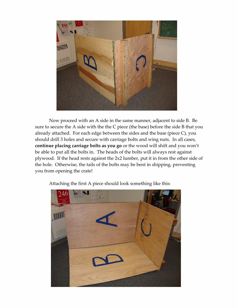
Now proceed with an A side in the same manner, adjacent to side B. Be
sure to secure the A side with the the C piece (the base) before the side B that you
already attached. For each edge between the sides and the base (piece C), you
should drill 3 holes and secure with carriage bolts and wing nuts. In all cases,
continue placing carriage bolts as you go or the wood will shift and you won’t
be able to put all the bolts in. The heads of the bolts will always rest against
plywood. If the head rests against the 2x2 lumber, put it in from the other side of
the hole. Otherwise, the tails of the bolts may be bent in shipping, preventing
you from opening the crate!
Attaching the first A piece should look something like this:

It may help to stand the crate up to attach piece A to piece B, as seen
below. For each of the edges between the A and B sides, you should make 6
carriage bolt holes, spaced evenly with one hole near each end.
Attach the other B side and the other A side just as you did the other two
pieces, rotating and/or standing the crate each time so that the B pieces are
opposite each other, as are the A pieces.

Once you have all the sides attached, tip the crate over and attach the top,
the other C piece (the one without the H-pieces attached). The holes in the edges
along the top should mimic the base: 4 hole per edge.
Finally, you should create unique marks on at least the edges between one
A side and one B side across both the side and the base. Also, you should put
one unique mark across an edge between one side and the top piece. These
marks will indicate which pieces go where when you disassemble and
reassemble the crate.

4.3 Tool-Less (Dis)Assembly of Completed Crate
When disassembled, the crate can be stored in sections against a wall,
behind shelves, or in a corner to save space. Assembly from this state begins by
placing the base of the crate on the floor with the 4x4’s on the bottom. Do NOT
place the robot on this platform or walk across it. Base is not strong enough
without the sides attached to it.
Next, place a narrow side (side A) on the base with the 2x2 lumber facing
out. The side straddle the 4”x”4 lumber that’s under the plywood base. Now
secure it to the base with the ¼” carriage bolts and wing nuts. The heads of the
bolts should be facing the floor. That way, when the pallet lifter picks up the
crate, it won’t be lifting against the tail of the bolts. The heads of the carriage
bolts will always rest on plywood.
Continue placing the sides of the crate. You can proceed with either a side
B or the remaining side A. Of course, once you have three sides in place, you
should pack in the robot. Be sure to pad the robot from all 6 sides of the crate
and secure it to the base (it is ok to make a few holes in the base). It is also a
good idea to place the robot upon supports so that the drive train is not
supporting the robot. If you skip this step, the robot resting on its wheels for
weeks may warp the axles. Even with the robot supported on something beside
the wheels, you should also tie it down to the base. Drill holes as necessary in
the base, however be sure that you don’t create obstructions between the 4x4’s.

Once the robot is packed into crate, secure the remaining side and top.
Next, you need to wrap or bind the crate to meet shipping regulations. The crate
does NOT need to be sealed. Using the shrink wrap, make several circles around
the crate, stretching the film, to create this binding. The finished wrap only
needs to cover a few feet of the crate’s height, preferably near the middle. The
point of the binding is to provide a visual indication that the package has not
been opened during the shipping process. It is a requirement of shipping
regulations.