Embed Size (px)
Citation preview
Coordinate Measuring Machine6
In every industry, there are ever diversifying needs for measuring machines - high-accuracy measurement of parts
manufactured with increasingly high accuracy, reduction in measurement time during the inspection, improvement in
throughput, measurement of parts having complicated shapes, etc.
XYZAX AXCEL achieves higher accuracy, higher drive speed and a wider accuracy guarantee temperature range.
What’s more, it allows various types of probe system to be selected as appropriate for the intended purpose, making it
possible to deal with any kind of application.
XYZAX AXCEL - a machine that we have positioned as a new global standard - meets the increasingly diverse needs.
A global standard 3D coordinate measuring machine featuring high accuracy, high speed and high environmental resistance and supporting a variety of probe systems
Coordinate Measuring Machine 7
Coordinate Measuring Machine8
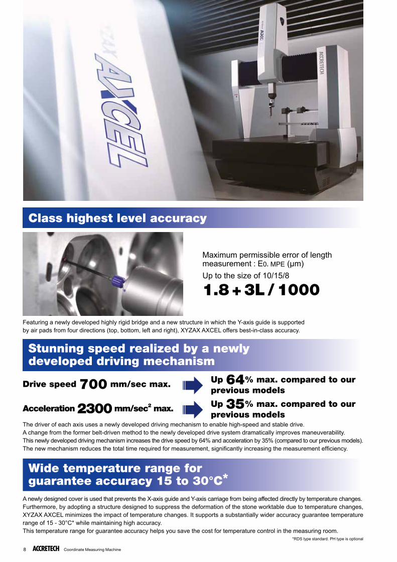
Maximum permissible error of length measurement : E0, MPE (µm)Up to the size of 10/15/8
1.8+3L /1000
The driver of each axis uses a newly developed driving mechanism to enable high-speed and stable drive.A change from the former belt-driven method to the newly developed drive system dramatically improves maneuverability.This newly developed driving mechanism increases the drive speed by 64% and acceleration by 35% (compared to our previous models).The new mechanism reduces the total time required for measurement, signifi cantly increasing the measurement effi ciency.
A newly designed cover is used that prevents the X-axis guide and Y-axis carriage from being affected directly by temperature changes.Furthermore, by adopting a structure designed to suppress the deformation of the stone worktable due to temperature changes, XYZAX AXCEL minimizes the impact of temperature changes. It supports a substantially wider accuracy guarantee temperature range of 15 - 30°C* while maintaining high accuracy.This temperature range for guarantee accuracy helps you save the cost for temperature control in the measuring room.
*RDS type standard. PH type is optional
Class highest level accuracy
Stunning speed realized by a newlydeveloped driving mechanism
Wide temperature range forguarantee accuracy 15 to 30°C*
Featuring a newly developed highly rigid bridge and a new structure in which the Y-axis guide is supported by air pads from four directions (top, bottom, left and right), XYZAX AXCEL offers best-in-class accuracy.
Drive speed 700 mm/sec max. Up 64% max. compared to our previous models
Acceleration 2300 mm/sec2 max. Up 35% max. compared to our previous models
Coordinate Measuring Machine 9
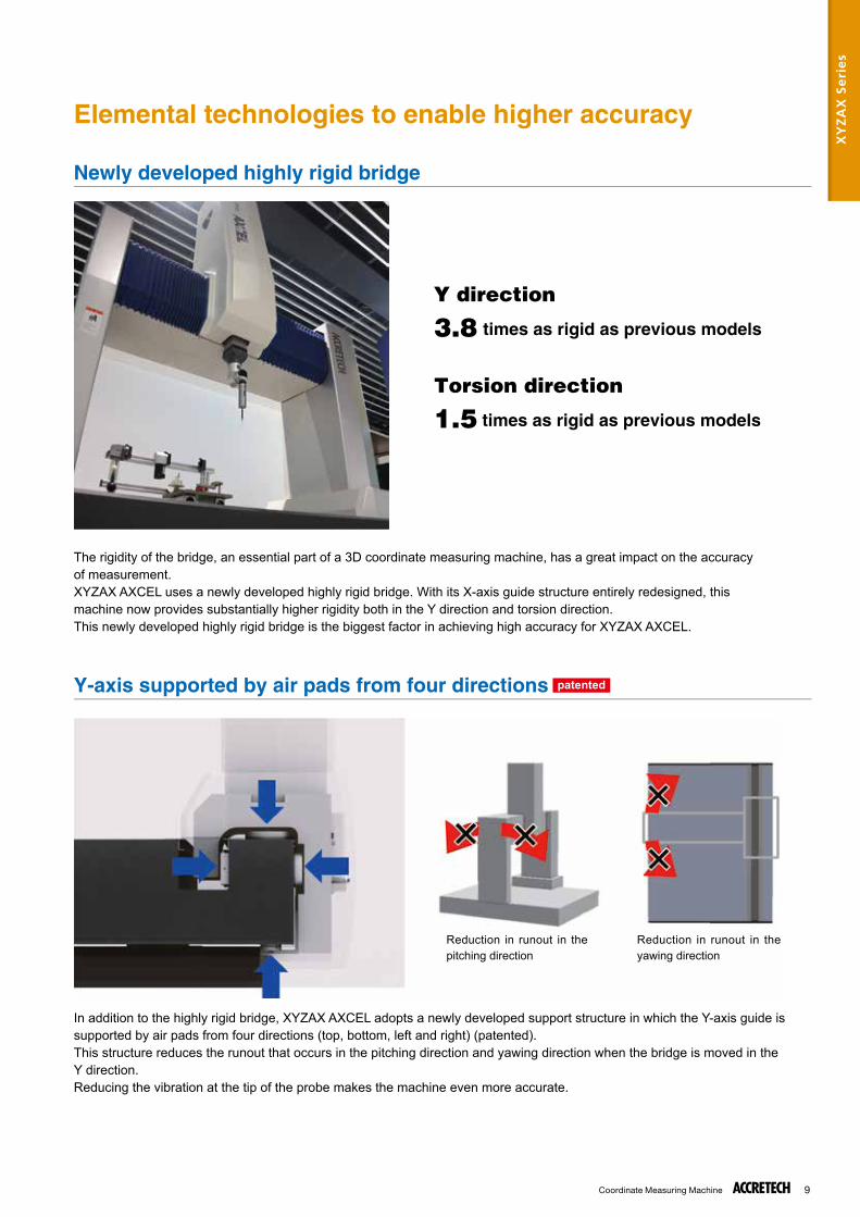
The rigidity of the bridge, an essential part of a 3D coordinate measuring machine, has a great impact on the accuracy of measurement.XYZAX AXCEL uses a newly developed highly rigid bridge. With its X-axis guide structure entirely redesigned, this machine now provides substantially higher rigidity both in the Y direction and torsion direction.This newly developed highly rigid bridge is the biggest factor in achieving high accuracy for XYZAX AXCEL.
In addition to the highly rigid bridge, XYZAX AXCEL adopts a newly developed support structure in which the Y-axis guide is supported by air pads from four directions (top, bottom, left and right) (patented).This structure reduces the runout that occurs in the pitching direction and yawing direction when the bridge is moved in the Y direction.Reducing the vibration at the tip of the probe makes the machine even more accurate.
Y direction
3.8 times as rigid as previous models
Torsion direction
1.5 times as rigid as previous models
Reduction in runout in the pitching direction
Reduction in runout in the yawing direction
Elemental technologies to enable higher accuracy
Newly developed highly rigid bridge
Y-axis supported by air pads from four directions patented
XY
ZA
X S
eri
es
Coordinate Measuring Machine10
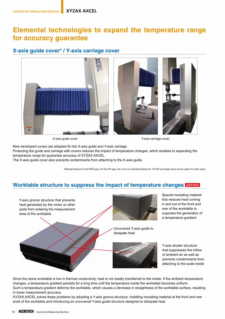
New developed covers are adopted for the X-axis guide and Y-axis carriage.Protecting the guide and carriage with covers reduces the impact of temperature changes, which enables to expanding the temperature range for guarantee accuracy of XYZAX AXCEL.The X-axis guide cover also prevents contaminants from attaching to the X-axis guide.
*Standard feature for the RDS type. For the PH type, the cover is a standard feature for 10/10/6 and larger sizes and an option for other sizes.
Since the stone worktable is low in thermal conductivity, heat is not readily transferred to the inside. If the ambient temperature changes, a temperature gradient persists for a long time until the temperature inside the worktable becomes uniform.Such a temperature gradient deforms the worktable, which causes a decrease in straightness of the worktable surface, resulting in lower measurement accuracy.XYZAX AXCEL solves these problems by adopting a Y-axis groove structure, installing insulating material at the front and rear ends of the worktable and introducing an uncovered Y-axis guide structure designed to dissipate heat.
X-axis guide cover Y-axis carriage cover
Y-axis groove structure that prevents heat generated by the motor or other parts from entering the measurement area of the worktable
Special insulating material that reduces heat coming in and out of the front and rear of the worktable to suppress the generation of a temperature gradient
Y-axis shutter structure that suppresses the infl ow of ambient air as well as prevents contaminants from attaching to the scale inside
Uncovered Y-axis guide to dissipate heat
Elemental technologies to expand the temperature range for accuracy guarantee
X-axis guide cover* / Y-axis carriage cover
Worktable structure to suppress the impact of temperature changes patented
Coordinate Measuring Machine XYZAX AXCEL
Coordinate Measuring Machine 11
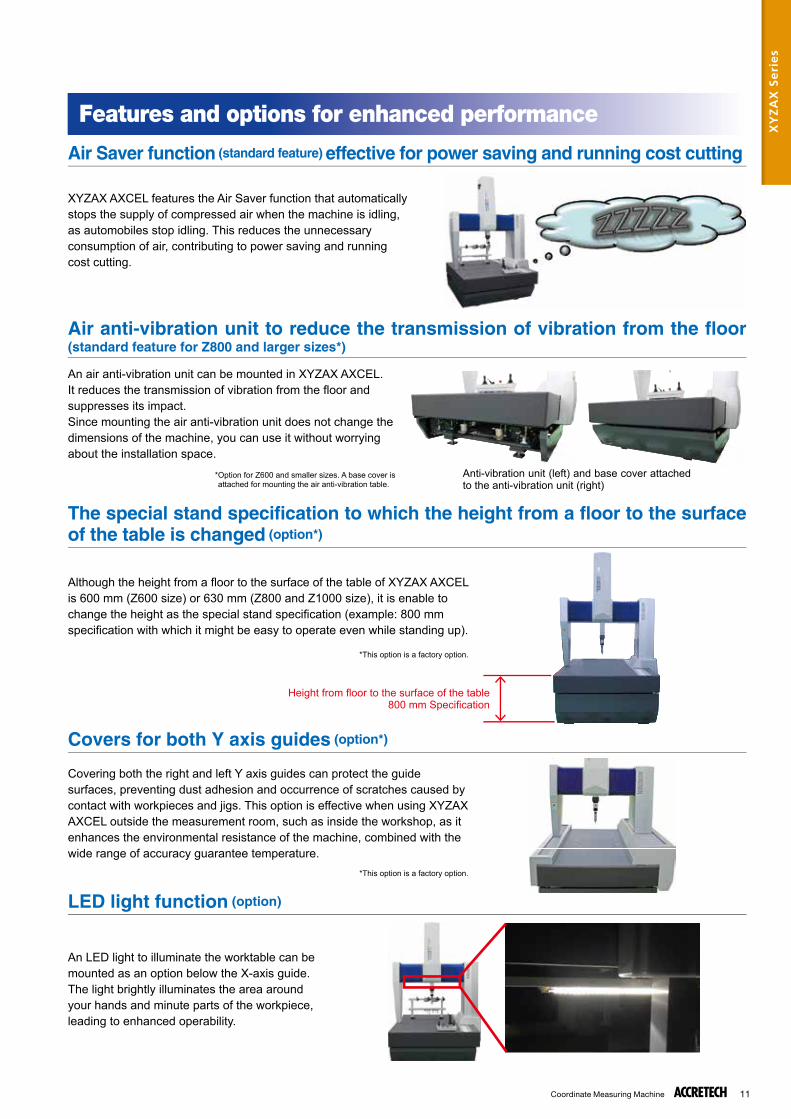
XYZAX AXCEL features the Air Saver function that automatically stops the supply of compressed air when the machine is idling, as automobiles stop idling. This reduces the unnecessary consumption of air, contributing to power saving and running cost cutting.
Although the height from a fl oor to the surface of the table of XYZAX AXCEL is 600 mm (Z600 size) or 630 mm (Z800 and Z1000 size), it is enable to change the height as the special stand specifi cation (example: 800 mm specifi cation with which it might be easy to operate even while standing up).
Covering both the right and left Y axis guides can protect the guide surfaces, preventing dust adhesion and occurrence of scratches caused by contact with workpieces and jigs. This option is effective when using XYZAX AXCEL outside the measurement room, such as inside the workshop, as it enhances the environmental resistance of the machine, combined with the wide range of accuracy guarantee temperature.
An LED light to illuminate the worktable can be mounted as an option below the X-axis guide.The light brightly illuminates the area around your hands and minute parts of the workpiece, leading to enhanced operability.
Anti-vibration unit (left) and base cover attached to the anti-vibration unit (right)
Height from fl oor to the surface of the table800 mm Specifi cation
Air Saver function (standard feature) effective for power saving and running cost cutting
Air anti-vibration unit to reduce the transmission of vibration from the floor(standard feature for Z800 and larger sizes*)
The special stand specification to which the height from a floor to the surface of the table is changed (option*)
Covers for both Y axis guides (option*)
LED light function (option)
Features and options for enhanced performance
An air anti-vibration unit can be mounted in XYZAX AXCEL. It reduces the transmission of vibration from the fl oor and suppresses its impact.Since mounting the air anti-vibration unit does not change the dimensions of the machine, you can use it without worrying about the installation space.
* Option for Z600 and smaller sizes. A base cover is attached for mounting the air anti-vibration table.
*This option is a factory option.
*This option is a factory option.
XY
ZA
X S
eri
es
Coordinate Measuring Machine12
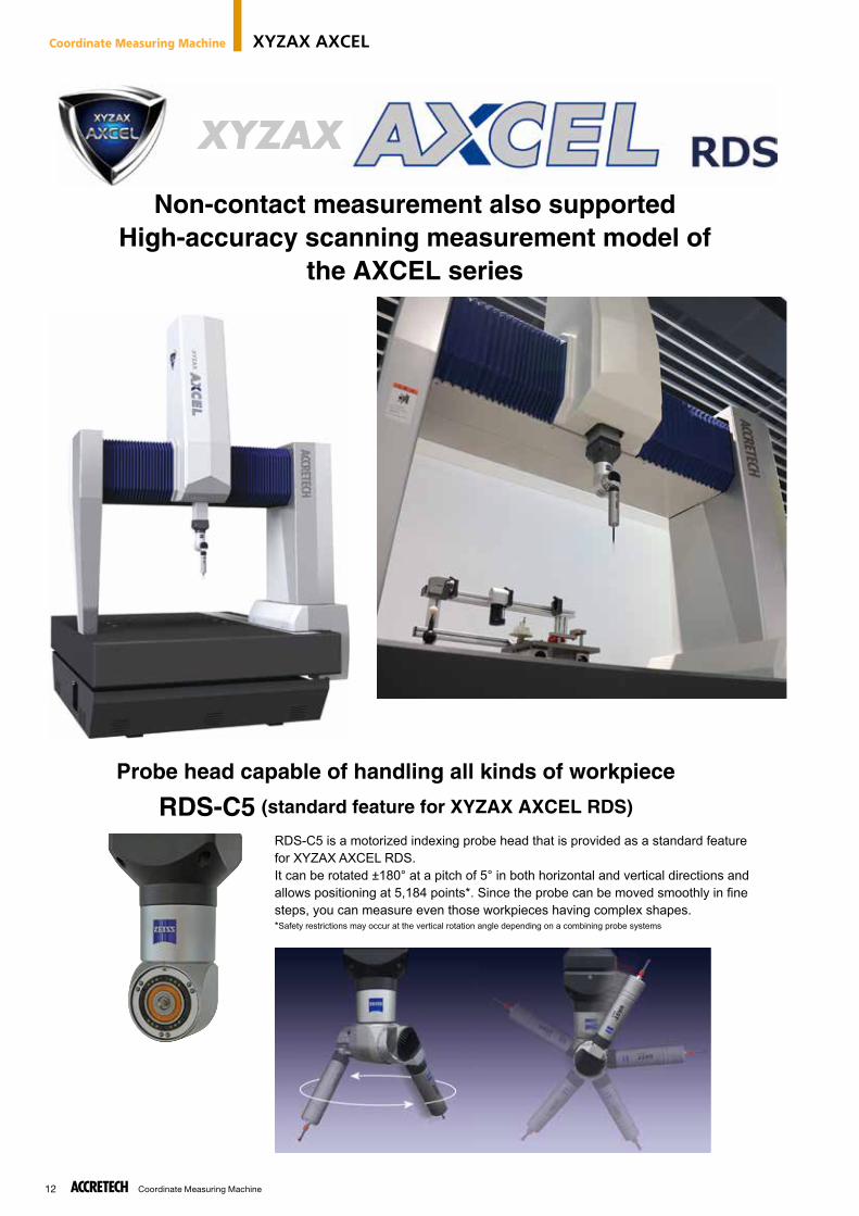
Non-contact measurement also supportedHigh-accuracy scanning measurement model of
the AXCEL series
Probe head capable of handling all kinds of workpiece
RDS-C5 (standard feature for XYZAX AXCEL RDS)
RDS-C5 is a motorized indexing probe head that is provided as a standard feature for XYZAX AXCEL RDS.It can be rotated ±180° at a pitch of 5° in both horizontal and vertical directions and allows positioning at 5,184 points*. Since the probe can be moved smoothly in fi ne steps, you can measure even those workpieces having complex shapes.*Safety restrictions may occur at the vertical rotation angle depending on a combining probe systems
Coordinate Measuring Machine XYZAX AXCEL
Coordinate Measuring Machine 13
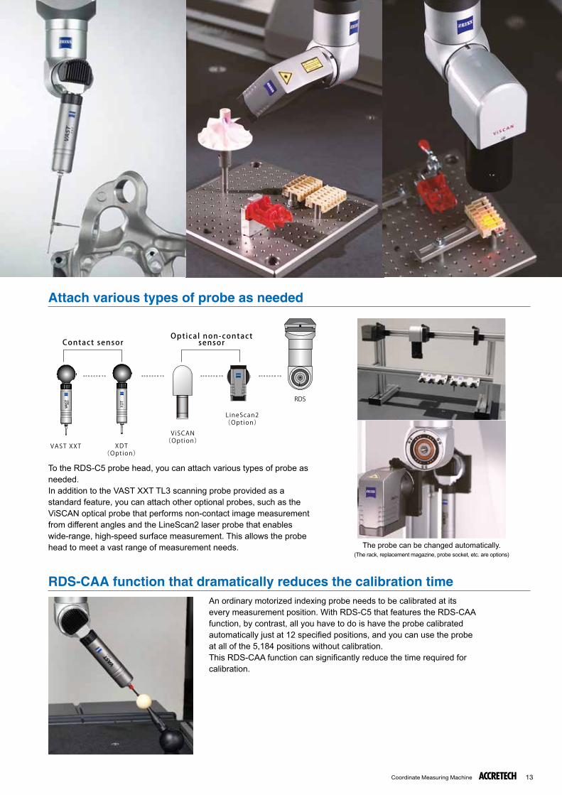
RDS
VAST XXT XDT(Option)
ViSCAN(Option)
LineScan2
Contact sensorOptical non-contact
sensor
(Option)
XDT
To the RDS-C5 probe head, you can attach various types of probe as needed.In addition to the VAST XXT TL3 scanning probe provided as a standard feature, you can attach other optional probes, such as the ViSCAN optical probe that performs non-contact image measurement from different angles and the LineScan2 laser probe that enables wide-range, high-speed surface measurement. This allows the probe head to meet a vast range of measurement needs.
An ordinary motorized indexing probe needs to be calibrated at its every measurement position. With RDS-C5 that features the RDS-CAA function, by contrast, all you have to do is have the probe calibrated automatically just at 12 specified positions, and you can use the probe at all of the 5,184 positions without calibration.This RDS-CAA function can significantly reduce the time required for calibration.
The probe can be changed automatically.(The rack, replacement magazine, probe socket, etc. are options)
Attach various types of probe as needed
RDS-CAA function that dramatically reduces the calibration time
Coordinate Measuring Machine14
Measurementmethod
Axial directionstylus length (mm)
Horizontal directionstylus length (mm)
Maximumstylus weight (g)
Minimum stylusball diameter (mm)
VAST XXT TL3 (standard)
Point / passivescanning 30 - 150 Max. 65 Max. 15
Φ 0.3VAST XXT TL4 (option)
Point / passivescanning 125 - 250 Max. 40 Max. 10
XDT (option) Point 30 - 150 Max. 65 Max. 15
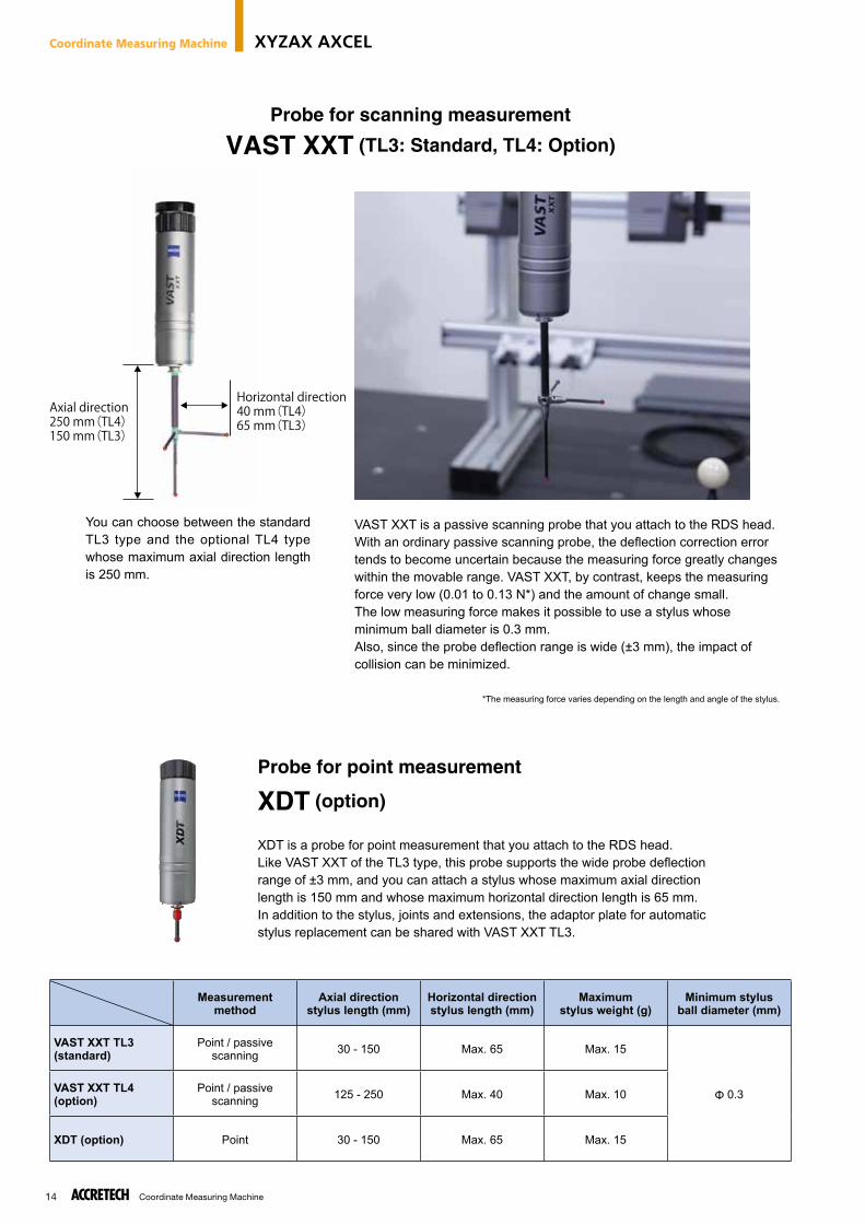
Horizontal direction40 mm(TL4)65 mm(TL3)
Axial direction250 mm(TL4)150 mm(TL3)
VAST XXT is a passive scanning probe that you attach to the RDS head.With an ordinary passive scanning probe, the deflection correction error tends to become uncertain because the measuring force greatly changes within the movable range. VAST XXT, by contrast, keeps the measuring force very low (0.01 to 0.13 N*) and the amount of change small.The low measuring force makes it possible to use a stylus whose minimum ball diameter is 0.3 mm.Also, since the probe deflection range is wide (±3 mm), the impact of collision can be minimized.
*The measuring force varies depending on the length and angle of the stylus.
XDT is a probe for point measurement that you attach to the RDS head.Like VAST XXT of the TL3 type, this probe supports the wide probe deflection range of ±3 mm, and you can attach a stylus whose maximum axial direction length is 150 mm and whose maximum horizontal direction length is 65 mm.In addition to the stylus, joints and extensions, the adaptor plate for automatic stylus replacement can be shared with VAST XXT TL3.
You can choose between the standard TL3 type and the optional TL4 type whose maximum axial direction length is 250 mm.
Probe for scanning measurement
VAST XXT (TL3: Standard, TL4: Option)
Probe for point measurement
XDT (option)
Coordinate Measuring Machine XYZAX AXCEL
Coordinate Measuring Machine 15
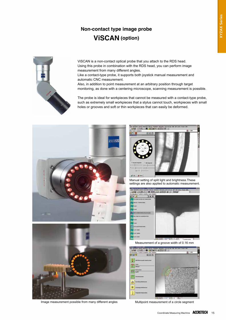
Non-contact type image probe
ViSCAN (option)
ViSCAN is a non-contact optical probe that you attach to the RDS head.Using this probe in combination with the RDS head, you can perform image measurement from many different angles.Like a contact-type probe, it supports both joystick manual measurement and automatic CNC measurement.Also, in addition to point measurement at an arbitrary position through target monitoring, as done with a centering microscope, scanning measurement is possible.
The probe is ideal for workpieces that cannot be measured with a contact-type probe, such as extremely small workpieces that a stylus cannot touch, workpieces with small holes or grooves and soft or thin workpieces that can easily be deformed.
Manual setting of split light and brightness.These settings are also applied to automatic measurement.
Measurement of a groove width of 0.16 mm
Multipoint measurement of a circle segmentImage measurement possible from many different angles
XY
ZA
X S
eri
es
Coordinate Measuring Machine16
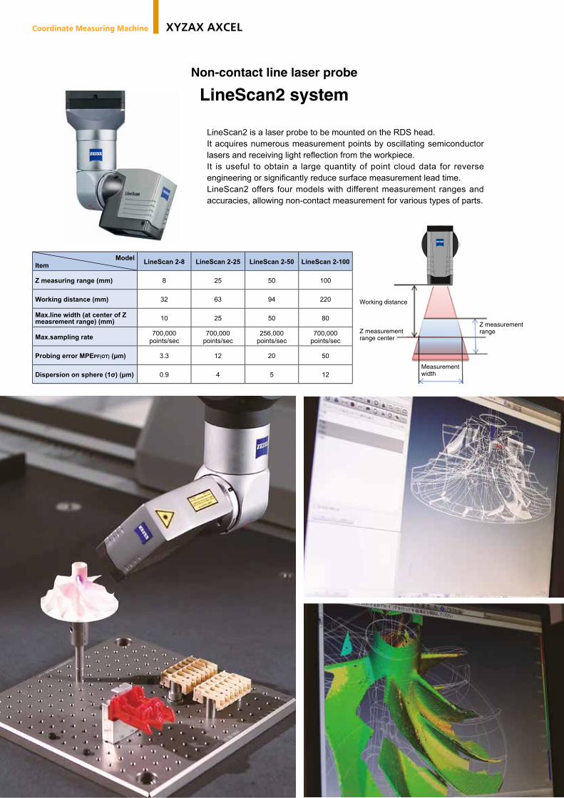
ModelItem LineScan 2-8 LineScan 2-25 LineScan 2-50 LineScan 2-100
Z measuring range (mm) 8 25 50 100
Working distance (mm) 32 63 94 220
Max.line width (at center of Z measrement range) (mm) 10 25 50 80
Max.sampling rate 700,000points/sec
700,000points/sec
256,000points/sec
700,000points/sec
Probing error MPEPF(OT) (μm) 3.3 12 20 50
Dispersion on sphere (1σ) (μm) 0.9 4 5 12
Working distance
Z measurementrange center
Z measurementrange
Measurementwidth
Non-contact line laser probe
LineScan2 system
LineScan2 is a laser probe to be mounted on the RDS head.It acquires numerous measurement points by oscillating semiconductor lasers and receiving light refl ection from the workpiece.It is useful to obtain a large quantity of point cloud data for reverse engineering or signifi cantly reduce surface measurement lead time.LineScan2 offers four models with different measurement ranges and accuracies, allowing non-contact measurement for various types of parts.
Coordinate Measuring Machine XYZAX AXCEL
Coordinate Measuring Machine 17
Measurement example of a specular fi nished surface with LineScan2-8
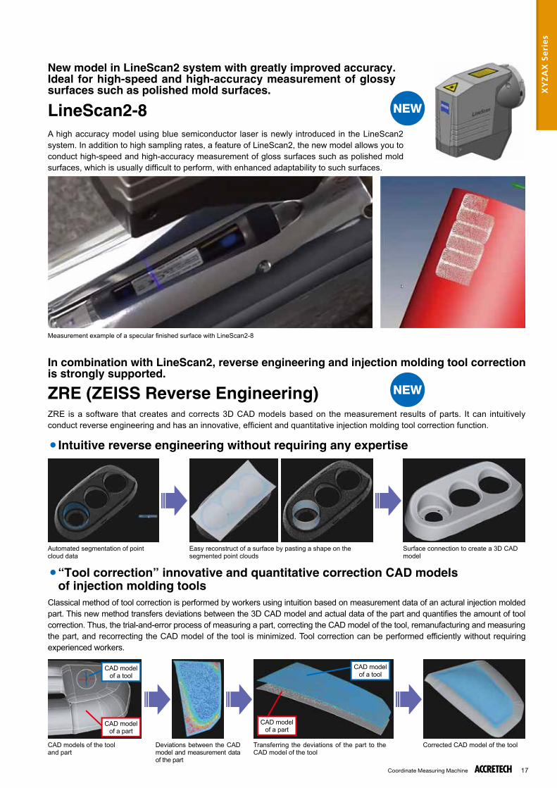
Automated segmentation of point cloud data
Surface connection to create a 3D CAD model
Easy reconstruct of a surface by pasting a shape on the segmented point clouds
CAD models of the tooland part
Corrected CAD model of the toolDeviations between the CAD model and measurement data of the part
Transferring the deviations of the part to the CAD model of the tool
CAD modelof a tool
CAD modelof a part
CAD modelof a part
CAD modelof a tool
New model in LineScan2 system with greatly improved accuracy.Ideal for high-speed and high-accuracy measurement of glossy surfaces such as polished mold surfaces.
In combination with LineScan2, reverse engineering and injection molding tool correctionis strongly supported.
ZRE (ZEISS Reverse Engineering)
LineScan2-8A high accuracy model using blue semiconductor laser is newly introduced in the LineScan2 system. In addition to high sampling rates, a feature of LineScan2, the new model allows you to conduct high-speed and high-accuracy measurement of gloss surfaces such as polished mold surfaces, which is usually diffi cult to perform, with enhanced adaptability to such surfaces.
ZRE is a software that creates and corrects 3D CAD models based on the measurement results of parts. It can intuitively conduct reverse engineering and has an innovative, effi cient and quantitative injection molding tool correction function.
Classical method of tool correction is performed by workers using intuition based on measurement data of an actural injection molded part. This new method transfers deviations between the 3D CAD model and actual data of the part and quantifi es the amount of tool correction. Thus, the trial-and-error process of measuring a part, correcting the CAD model of the tool, remanufacturing and measuring the part, and recorrecting the CAD model of the tool is minimized. Tool correction can be performed efficiently without requiring experienced workers.
● Intuitive reverse engineering without requiring any expertise
● “Tool correction” innovative and quantitative correction CAD modelsof injection molding tools
NEW
NEW
XY
ZA
X S
eri
es
Coordinate Measuring Machine18
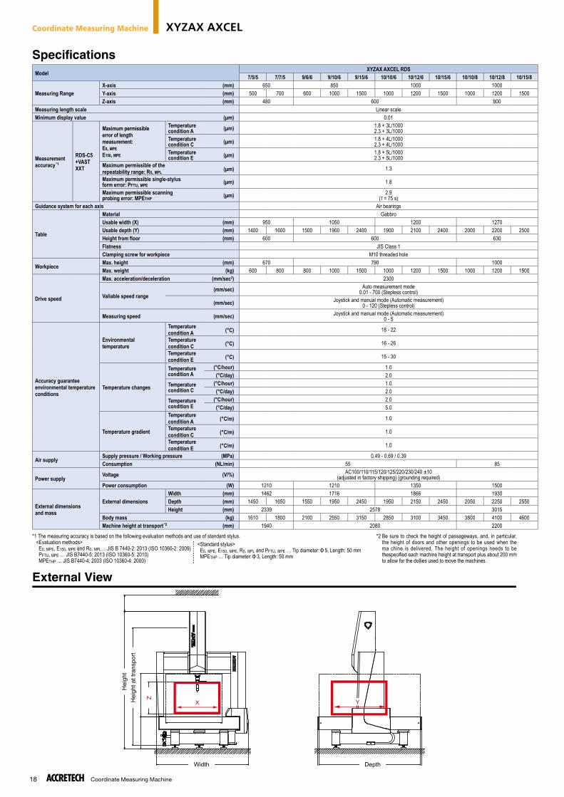
Specifications
External View
X Y
DepthWidth
Hei
ght
Hei
ght a
t tra
nspo
rt
Z
*2 Be sure to check the height of passageways, and, in particular, the height of doors and other openings to be used when the ma chine is delivered. The height of openings needs to be thespecifi ed each machine height at transport plus about 200 mm to allow for the dollies used to move the machines.
ModelXYZAX AXCEL RDS
7/5/5 7/7/5 9/6/6 9/10/6 9/15/6 10/10/6 10/12/6 10/15/6 10/10/8 10/12/8 10/15/8
Measuring RangeX-axis (mm) 650 850 1000 1000Y-axis (mm) 500 700 600 1000 1500 1000 1200 1500 1000 1200 1500Z-axis (mm) 480 600 800
Measuring length scale Linear scaleMinimum display value (µm) 0.01
Measurement accuracy *1
RDS-C5+VASTXXT
Maximum permissible error of length measurement:E0, MPEE150, MPE
Temperaturecondition A (µm) 1.8 + 3L/1000
2.3 + 3L/1000Temperaturecondition C (µm) 1.8 + 4L/1000
2.3 + 4L/1000Temperaturecondition E (µm) 1.8 + 5L/1000
2.3 + 5L/1000Maximum permissible of therepeatability range: R0, MPL (µm) 1.3
Maximum permissible single-stylusform error: PFTU, MPE (µm) 1.8
Maximum permissible scanningprobing error: MPETHP (µm) 2.9
(T = 75 s)Guidance system for each axis Air bearings
Table
Material GabbroUsable width (X) (mm) 950 1050 1200 1270Usable depth (Y) (mm) 1400 1600 1500 1900 2400 1900 2100 2400 2000 2200 2500Height from floor (mm) 600 600 630Flatness JIS Class 1Clamping screw for workpiece M10 threaded hole
WorkpieceMax. height (mm) 670 790 1000Max. weight (kg) 600 800 800 1000 1500 1000 1200 1500 1000 1200 1500
Drive speed
Max. acceleration/deceleration (mm/sec2) 2300
Valiable speed range (mm/sec) Auto measurement mode
0.01 - 700 (Stepless control)
(mm/sec) Joystick and manual mode (Automatic measurement)0 - 120 (Stepless control)
Measuring speed (mm/sec) Joystick and manual mode (Automatic measurement)0 - 5
Accuracy guarantee environmental temperatureconditions
Environmentaltemperature
Temperaturecondition A (°C) 18 - 22
Temperaturecondition C (°C) 16 - 26
Temperaturecondition E (°C) 15 - 30
Temperature changes
Temperaturecondition A
(°C/hour) 1.0 (°C/day) 2.0
Temperaturecondition C
(°C/hour) 1.0 (°C/day) 2.0
Temperaturecondition E
(°C/hour) 2.0 (°C/day) 5.0
Temperature gradient
Temperaturecondition A (°C/m) 1.0
Temperaturecondition C (°C/m) 1.0
Temperaturecondition E (°C/m) 1.0
Air supplySupply pressure / Working pressure (MPa) 0.49 - 0.69 / 0.39Consumption (NL/min) 55 85
Power supplyVoltage (V/%) AC100/110/115/120/125/220/230/240 ±10
(adjusted in factory shipping) (grounding required)Power consumption (W) 1210 1210 1350 1500
External dimensionsand mass
External dimensionsWidth (mm) 1462 1716 1866 1930Depth (mm) 1450 1650 1550 1950 2450 1950 2150 2450 2050 2250 2550Height (mm) 2339 2578 3015
Body mass (kg) 1610 1800 2100 2550 3150 2850 3100 3450 3800 4100 4600Machine height at transport *2 (mm) 1940 2080 2200
*1 The measuring accuracy is based on the following evaluation methods and use of standard stylus. <Evaluation methods> E0, MPE, E150, MPE and R0, MPL … JIS B 7440-2: 2013 (ISO 10360-2: 2009) PFTU, MPE … JIS B7440-5: 2013 (ISO 10360-5: 2010) MPETHP … JIS B7440-4: 2003 (ISO 10360-4: 2000)
<Standard stylus> E0, MPE, E150, MPE, R0, MPL and PFTU, MPE … Tip diameter: Φ 5, Length: 50 mm MPETHP … Tip diameter: Φ 3, Length: 50 mm
<Standard stylus> E MPE
Coordinate Measuring Machine XYZAX AXCEL
Coordinate Measuring Machine 19
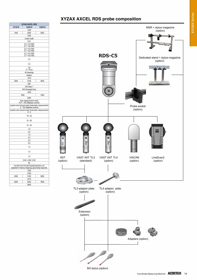
RDS-C5
XDT(option)
VAST XXT TL3(standard)
VAST XXT TL4(option)
ViSCAN(option)
LineScan2(option)
XYZAX AXCEL RDS プローブ構成MSR + stylus magazine
(option)
Dedicated stand + stylus magazine(option)
Probe socket(option)
TL3 adaptor plate(option)
TL4 adaptor plate(option)
Extension(option)
Adapters (option)
M3 stylus (option)
XYZAX AXCEL RDS probe compositionXYZAX AXCEL RDS
12/15/10 12/20/10 12/25/101200
1500 2000 25001000
Linear scale0.01
2.2 + 3L/10002.7 + 3L/10002.2 + 4L/10002.7 + 4L/10002.2 + 5L/10002.7 + 5L/1000
2.2
2.5
3.8(T = 75 s)
Air bearingsGabbro1470
2500 3100 3600630
JIS Class 1M10 threaded hole
12001500 1000
2300Auto measurement mode
0.01 - 700 (Stepless control)Joystick and manual mode (Automatic measurement)
0 - 120 (Stepless control)Joystick and manual mode (Automatic measurement)
0 - 5
18 - 22
16 - 26
15 - 30
1.02.01.02.02.05.0
1.0
1.0
1.0
0.49 - 0.69 / 0.3990
AC100/110/115/120/125/220/230/240 ±10(adjusted in factory shipping) (grounding required)
15002180
2550 3150 36503415
5200 6300 76002600
XY
ZA
X S
eri
es