Embed Size (px)
Citation preview
Available online at www.sciencedirect.com
www.elsevier.com/locate/compstruct
Composite Structures 84 (2008) 350–361
A global-local higher order theory for multilayered shellsand the analysis of laminated cylindrical shell panels
Wu Zhen a,b,*, Chen Wanji b,a
a State Key Laboratory for Structural Analysis of Industrial Equipment, Dalian University of Technology, Dalian 116023, Chinab Department of Aeronautics and Astronautics, Shenyang Institute of Aeronautical Engineering, Shenyang 110034, China
Available online 10 October 2007
Abstract
Based on the global-local superposition technique proposed by Li and Liu [Li XY, Liu D. Generalized laminate theories based ondouble superposition hypothesis. Int J Numer Meth Eng 1997;40:1197–212.], a global-local higher order laminated shell model is pro-posed for predicting both displacement and stress distributions through the thickness of laminated shells. This shell model satisfies trans-verse shear stress continuity conditions at interfaces as well as free surface conditions of transverse shear stresses. The merit of this modelis that transverse shear stresses can be accurately predicted directly from constitutive equations without smoothing techniques. Cylindri-cal bending of laminated and sandwich shell panels is chosen to assess the present model wherein the results from several 2D laminatedshell models and three-dimensional elasticity solution are available for comparison. In addition, thermal bending and thermal expansionof laminated cylindrical shell panels are also considered in this paper.� 2007 Elsevier Ltd. All rights reserved.
Keywords: Global-local superposition technique; Global-local higher order laminated shell model; Transverse shear stress continuity; Thermal stress
1. Introduction
Since laminated composite and sandwich shells due totheir high specific strength and low specific density werewidely used in the aeronautical and aerospace industries,numerous investigators have used a variety of models forthe analysis of laminated structures. Based on a seriesexpansion in term of the thickness coordinate, the first-order shear deformation shell theory [1] and the globalhigher order theories [2–5] are developed to predict the glo-bal response of laminated shells. However, these modelsare inadequate for accurately predicting the interlaminarstresses from the constitutive equations, as the continuityconditions of transverse stress at interfaces cannot be a pri-
0263-8223/$ - see front matter � 2007 Elsevier Ltd. All rights reserved.
doi:10.1016/j.compstruct.2007.10.006
* Corresponding author. Address: State Key Laboratory for StructuralAnalysis of Industrial Equipment, Dalian University of Technology,Dalian 116023, China.
E-mail address: [email protected] (W. Zhen).
ori satisfied. Further layerwise displacement model [6], lay-erwise mixed model [7] and three-dimensional models[8–11] are proposed to accurately calculate local stressesof laminated shells. However, these models require hugecomputational cost for multilayered structures with com-plicated geometry.
Di Sciuva [12] developed a linear zig-zag model whichcan guarantee the continuity of transverse shear stresses.Moreover, the number of variables in this model is inde-pendent of the number of layers. Further the improvedzig-zag model [13,14] are presented. In addition, Choet al. [15] proposed a third-order zig-zag model that canprovide parabolic variation through thickness of trans-verse shear stresses. Moreover, this model is further devel-oped to predict the deformation and stresses of thicksmart composite shell under mechanical, thermal andelectric loads by Oh and Cho [16]. Cho and Kim [17] alsopresented a postprocessing method to predict the throughthe thickness stresses of laminated shells. Subsequently a
W. Zhen, C. Wanji / Composite Structures 84 (2008) 350–361 351
nine-noded doubly curved shell element based on higherorder zig-zag model is presented by Cho and Kim [18],in conjunction with a processing method. Recently Icardi[19] proposed a third-order zig-zag shell model for theanalysis of laminated shells with general lay-up. Compar-ison of numerical results shows that the zig-zag modelsare more accurate in comparison with other global higherorder models. On the other hand, the effects of higherorder expansion of Lame’s coefficients across the thick-ness on transverse stresses of laminated shells have beenstudied by Icardi and Ruotolo [20]. Although these men-tioned zig-zag models can satisfy transverse shear stressescontinuity conditions at interfaces, the three-dimensionalequilibrium equations are usually adopted to reasonablypredict interlaminar stresses. Cho and Kim [21] have stud-ied in detailed the equilibrium equation approach. More-over, they have concluded that the constitutive equationapproach is more attractive because the equilibrium equa-tion approach requires the higher derivatives of transversedisplacement that results in a numerical problem in prac-tice. Moreover, numerical results [15,19,20] show thattransverse shear stresses obtained from postprocessingmethod are still not accurate enough in comparison withthree-dimensional elasticity solutions.
To the best knowledge of the authors, it can not befound that displacement-based laminated shell modelspublished are able to predict accurately transverse shearstresses directly from the constitutive equations withoutany postprocessing methods. To fill in the existing gap,an attempt is made in this paper to propose a laminatedshell model based on the global-local superposition tech-nique proposed by Li and Liu [22]. Initial displacementfields of the present laminated shell model are composedof both global displacements and local displacements. Byenforcing free conditions of the transverse shear stresseson the upper and lower surfaces, and displacementsand transverse shear stresses continuity conditions atinterfaces, the number of unknowns is independent ofnumber of layer of laminates. Significant characteristicof the present model is that transverse shear stressescan be accurately computed directly from the constitutiveequations without smoothing.
2. Mathematical formulation
2.1. Preliminaries [23]
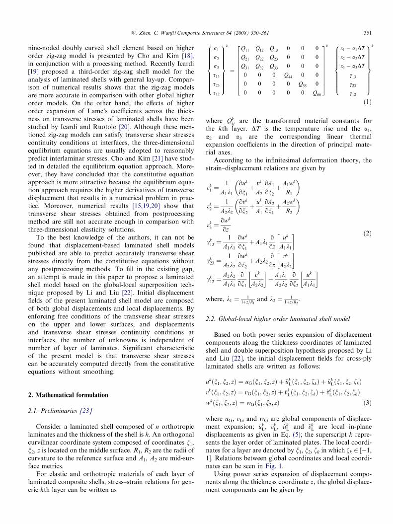
Consider a laminated shell composed of n orthotropiclaminates and the thickness of the shell is h. An orthogonalcurvilinear coordinate system composed of coordinates n1,n2, z is located on the middle surface. R1, R2 are the radii ofcurvature to the reference surface and A1, A2 are mid-sur-face metrics.
For elastic and orthotropic materials of each layer oflaminated composite shells, stress–strain relations for gen-eric kth layer can be written as
r1
r2
r3
s13
s23
s12
8>>>>>>>><>>>>>>>>:
9>>>>>>>>=>>>>>>>>;
k
¼
Q11 Q12 Q13 0 0 0
Q21 Q22 Q23 0 0 0
Q31 Q32 Q33 0 0 0
0 0 0 Q44 0 0
0 0 0 0 Q55 0
0 0 0 0 0 Q66
2666666664
3777777775
k e1 � a1DT
e2 � a2DT
e3 � a3DT
c13
c23
c12
8>>>>>>>><>>>>>>>>:
9>>>>>>>>=>>>>>>>>;
k
ð1Þ
where Qkij are the transformed material constants for
the kth layer. DT is the temperature rise and the a1,a2 and a3 are the corresponding linear thermalexpansion coefficients in the direction of principal mate-rial axes.
According to the infinitesimal deformation theory, thestrain–displacement relations are given by
ek1 ¼
1
A1k1
ouk
on1
þ vk
A2
oA1
on2
þ A1wk
R1
� �
ek2 ¼
1
A2k2
ovk
on2
þ uk
A1
oA2
on1
þ A2wk
R2
� �
ek3 ¼
owk
oz
ck13 ¼
1
A1k1
owk
on1
þ A1k1
o
ozuk
A1k1
� �
ck23 ¼
1
A2k2
owk
on2
þ A2k2
o
ozvk
A2k2
� �
ck12 ¼
A2k2
A1k1
o
on1
vk
A2k2
� �þ A1k1
A2k2
o
on2
uk
A1k1
� �
ð2Þ
where, k1 ¼ 11þz=R1
and k2 ¼ 11þz=R2
.
2.2. Global-local higher order laminated shell model
Based on both power series expansion of displacementcomponents along the thickness coordinates of laminatedshell and double superposition hypothesis proposed by Liand Liu [22], the initial displacement fields for cross-plylaminated shells are written as follows:
ukðn1; n2; zÞ ¼ uGðn1; n2; zÞ þ �ukLðn1; n2; fkÞ þ uk
Lðn1; n2; fkÞvkðn1; n2; zÞ ¼ vGðn1; n2; zÞ þ �vk
Lðn1; n2; fkÞ þ vkLðn1; n2; fkÞ
wkðn1; n2; zÞ ¼ wGðn1; n2; zÞ ð3Þ
where uG, vG and wG are global components of displace-ment expansion; �uk
L, �vkL, uk
L and vkL are local in-plane
displacements as given in Eq. (5); the superscript k repre-sents the layer order of laminated plates. The local coordi-nates for a layer are denoted by n1, n2, fk in which fk 2 [�1,1]. Relations between global coordinates and local coordi-nates can be seen in Fig. 1.
Using power series expansion of displacement compo-nents along the thickness coordinate z, the global displace-ment components can be given by
R
z
n
R
zL
h
φ
−nz
R
z
z
z
12
1
k
z
z
zθkζ
Fig. 1. Cylindrical shell panel geometry.
352 W. Zhen, C. Wanji / Composite Structures 84 (2008) 350–361
uGðn1; n2; zÞ ¼X5
i¼0
uiðn1; n2Þzi
vGðn1; n2; zÞ ¼X5
i¼0
viðn1; n2Þzi
wGðn1; n2; zÞ ¼X2
i¼0
wiðn1; n2Þzi
ð4Þ
The local displacement components can be written asfollows:
�ukLðn1; n2; fkÞ ¼ fkuk
1ðn1; n2Þ þ f2kuk
2ðn1; n2Þ�vk
Lðn1; n2; fkÞ ¼ fkvk1ðn1; n2Þ þ f2
kvk2ðn1; n2Þ
ukLðn1; n2; fkÞ ¼ f3
kuk3ðn1; n2Þ
vkLðn1; n2; fkÞ ¼ f3
kvk3ðn1; n2Þ
ð5Þ
where fk = akz � bk; ak ¼ 2zkþ1�zk
; bk ¼ zkþ1þzkzkþ1�zk
.
2.3. Displacement continuity conditions at interfaces
At present, the initial displacement fields include 6n + 15unknown variables, in which n denotes the total number oflayers in the laminated shells. It shows that the number ofvariables depends on the number of layers. Using displace-ment continuity conditions proposed by Li and Liu [22],4(n � 1) variables can be eliminated. This continuity condi-tions can be expressed by
�ukLðn1; n2; zkÞ ¼ �uk�1
L ðn1; n2; zkÞuk
Lðn1; n2; zkÞ ¼ uk�1L ðn1; n2; zkÞ
�vkLðn1; n2; zkÞ ¼ �vk�1
L ðn1; n2; zkÞvk
Lðn1; n2; zkÞ ¼ vk�1L ðn1; n2; zkÞ
ð6Þ
in which k = 2, 3, 4, . . ., n.
Nh ¼1
Rk2Wk
1ooh Wk
2ooh � � � Wk
6ooh Wk
7ooh Wk
8o2
oh2 þ 1 Wk9
o2
oh2
hNz ¼ 0 0 0 0 0 0 0 0 1 2z½ �Nw ¼ 0 0 0 0 0 0 0 1 z z2
� �Nhz ¼ oWk
1
oz �Wk
1
Rk2� � � oWk
7
oz �Wk
7
Rk2
oWk8
oz �Wk
8
Rk2þ 1
Rk2
� ooh � � � oW
oz
�hU ¼ v0 v1
1 v1 v2 v3 v4 v5 w0 w1 w2
�T:
2.4. Transverse shear stress continuity conditions at
interfaces
By enforcing the continuity conditions of transverseshear stresses at interfaces, 2(n � 1) degrees of freedomcan be eliminated. The transverse shear stress continuityconditions are given by
sk13ðn1; n2; zkÞ ¼ sk�1
13 ðn1; n2; zkÞsk
23ðn1; n2; zkÞ ¼ sk�123 ðn1; n2; zkÞ
ð7Þ
Using the free conditions of the transverse shear stresses onthe upper and lower surfaces, the number of the indepen-dent unknowns is reduced to 17. The final displacementfields for cross-ply laminated plates are
uk ¼ Uk1u0 þ Uk
2u11 þ Uk
3u1 þ Uk4u2 þ Uk
5u3
þ Uk6u4 þ Uk
7u5 þ Uk8
ow0
on1
þ Uk9
ow1
on1
þ Uk10
ow2
on1
vk ¼ Wk1v0 þWk
2v11 þWk
3v1 þWk4v2 þWk
5v3
þWk6v4 þWk
7v5 þWk8
ow0
on2
þWk9
ow1
on2
þWk10
ow2
on2
wk ¼ w0 þ zw1 þ z2w2
ð8Þ
in which, the expression of Uki and Wk
i can be found inAppendix.
3. Analytical solutions for laminated cylindrical shell panels
To conveniently compare the proposed model and otheravailable two-dimensional models, the cylindrical bendingof cross-ply laminated cylindrical shell panels subject tosinusoidal loading distribution q = q0 sin(ph//) on the topsurface is mainly considered herein. For cylindrical shellpanel, coordinates and radii are defined as follows:
ðn1; n2; zÞ ¼ ðx; h; zÞ; R1 ¼ 1; R2 ¼ R; A1 ¼ 1; A2 ¼ R
According to strain–displacement relations in Eq. (2) anddisplacement fields of present model in (8), the detailedexpression of strains can be written by
e ¼eh
ez
chz
8><>:
9>=>; ¼
Nh
Nz
Nhz
264
375U ð9Þ
Transverse displacement can be written by
w ¼ NwU ð10Þin which
þ z Wk10
o2
oh2 þ z2i
k10 � Wk
10
Rk2þ z2
Rk2
ooh
i
W. Zhen, C. Wanji / Composite Structures 84 (2008) 350–361 353
For a simply supported, infinitely long laminated shellpanel under cylindrical bending, the loads can be expressedas q = q0 sin(ph//) where, p = p//. By assuming
v0 ¼ V 0 cos ph; v11 ¼ V 1
1 cos ph; v1 ¼ V 1 cos ph;
v2 ¼ V 2 cos ph; v3 ¼ V 3 cos ph;
v4 ¼ V 4 cos ph; v5 ¼ V 5 cos ph; w0 ¼ W 0 sin ph;
w1 ¼ W 1 sin ph; w2 ¼ W 2 sin ph ð11Þ
the simply supported boundary conditions are automati-cally satisfied.
By substituting Eq. (11) into Eqs. (9) and (10), strainsand transverse displacement can be respectively written asfollows:
e ¼eh
ez
chz
8><>:
9>=>; ¼
Nh sin ph
Nz sin ph
Nhz cos ph
264
375U ð12Þ
w ¼ Nw sin phU ð13Þ
in which
Nh ¼�1
Rk2Wk
1p Wk2p � � � Wk
6p Wk7p Wk
8p2 þ 1 Wk9p2 þ z Wk
10p2 þ z2� �
Nz ¼ 0 0 0 0 0 0 0 0 1 2z½ �
Nhz ¼ oWk1
oz �Wk
1
Rk2� � � oWk
7
oz �Wk
7
Rk2p
oWk8
oz �Wk
8
Rk2þ 1
Rk2
� � � � p
oWk10
oz �Wk
10
Rk2þ z2
Rk2
� h iNw ¼ 0 0 0 0 0 0 0 1 z z2
� �U ¼ V 0 V 1
1 V 1 V 2 V 3 V 4 V 5 W 0 W 1 W 2
�T
The principle of virtual displacement can be written asZA
Xn
k¼1
Z zkþ1
zk
deTr dz
!dA ¼
ZA
dwq dA ð14Þ
Substituting Eqs. (12) and (13) into Eq. (14), followingequation can be obtained
Xn
k¼1
Z zkþ1
zk
N h N z N hz
� �Qk
N h
N z
N hz
264
375Udz ¼ qþ0 Nþw
� �T ð15Þ
where Qk ¼Q11 Q13 0Q13 Q33 00 0 Q44
24
35
k
. By solving Eq. (15), V0,
V 11, V1, V2, V3, V4, V5, W0, W1 and W2 can be obtained.
Moreover, in-plane and transverse shear stresses may becalculated from Eqs. (1) and (2).
4. Numerical examples
To assess present shell model, three typical problems ofcross-ply composite laminated cylindrical shell panels sub-jected to thermal/mechanical loadings are analyzed. At the
same time, we select several typical analytical results forcomparison with results of present theory.
Matsunaga[5]:
Based on global ninth-order model, in-planestress is predicted from constitutiveequation whereas transverse shear stress iscalculated from equilibrium equation.
Exact [8]:
Three-dimensional elasticity solution. ZZT-C [19]: Based on zig-zag theory, result is predictedfrom constitutive equations.
RHSDST-C[19]:
Based on refined higher order sheardeformation laminated shell theory, result ispredicted from constitutive equations.RHSDST-E[20]:
Based on refined higher order sheardeformation laminated shell theory, result ispredicted from equilibrium equations.
HSDST-E[20]:
Based on global higher order sheardeformation laminated shell theory, result ispresented from equilibrium equations.
Line missing
FSDST-E[20]:
Based on first-order shear deformationlaminated shell theory, result is predictedfrom equilibrium equations.
ZZT-E [15]:
Based on third-order zig-zag theory, resultis given from equilibrium equations.Present:
Present results as predicted fromconstitutive equations.where -C and -E denote constitutive equation and equilib-rium equation, respectively. Other acronyms in figures canbe obtained by using the same method.
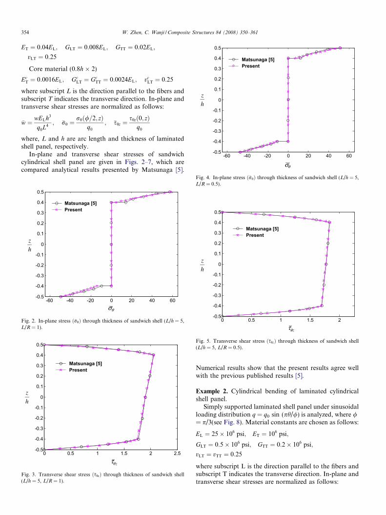
Example 1. Cylindrical bending of sandwich cylindricalshell panel.
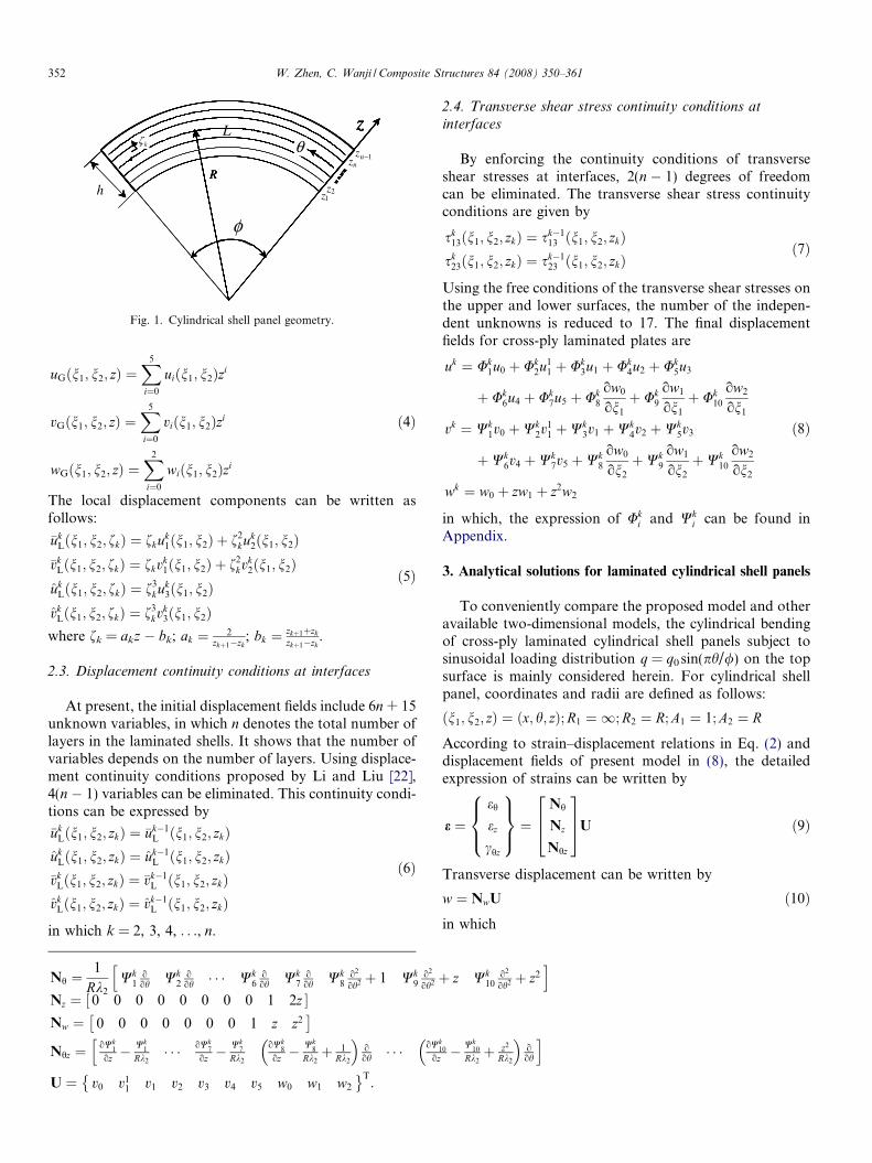
Sandwich cylindrical shell panels, simply supportedalong coordinate x and subjected to sinusoidalloading distribution q = q0 sin (ph//) on the top surface,are analyzed in this example (see Fig. 1), where / = L/Rand L is the arc length. Based on global ninth-order model, Matsunaga [5] has presented analyticalresults of this example. Material constants are chosen asfollows
Face sheets (0.1h � 2)
-60 -40 -20 0 20 40 60-0.5
-0.4
-0.3
-0.2
-0.1
0
0.1
0.2
0.3
0.4
0.5
Matsunaga [5]Present
θσ
h
z
354 W. Zhen, C. Wanji / Composite Structures 84 (2008) 350–361
ET ¼ 0:04EL; GLT ¼ 0:008EL; GTT ¼ 0:02EL;
vLT ¼ 0:25
Core material (0.8h � 2)
EcT ¼ 0:0016EL; Gc
LT ¼ GcTT ¼ 0:0024EL; vc
LT ¼ 0:25
where subscript L is the direction parallel to the fibers andsubscript T indicates the transverse direction. In-plane andtransverse shear stresses are normalized as follows:
�w ¼ wELh3
q0L4; �rh ¼
rhð/=2; zÞq0
; �shz ¼shzð0; zÞ
q0
where, L and h are arc length and thickness of laminatedshell panel, respectively.
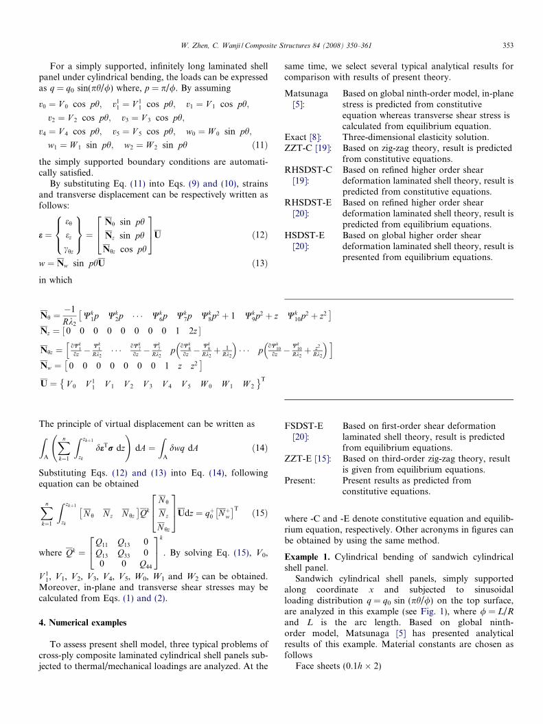
In-plane and transverse shear stresses of sandwichcylindrical shell panel are given in Figs. 2–7, which arecompared analytical results presented by Matsunaga [5].
-60 -40 -20 0 20 40 60-0.5
-0.4
-0.3
-0.2
-0.1
0
0.1
0.2
0.3
0.4
0.5
Matsunaga [5]Present
h
z
θσ
Fig. 2. In-plane stress ð�rhÞ through thickness of sandwich shell (L/h = 5,L/R = 1).
0 0.5 1 1.5 2 2.5-0.5
-0.4
-0.3
-0.2
-0.1
0
0.1
0.2
0.3
0.4
0.5
Matsunaga [5]Present
h
z
zθτ
Fig. 3. Transverse shear stress ð�shzÞ through thickness of sandwich shell(L/h = 5, L/R = 1).
Fig. 4. In-plane stress ð�rhÞ through thickness of sandwich shell (L/h = 5,L/R = 0.5).
0 0.5 1 1.5 2-0.5
-0.4
-0.3
-0.2
-0.1
0
0.1
0.2
0.3
0.4
0.5
Matsunaga [5]Present
zθτ
h
z
Fig. 5. Transverse shear stress ð�shzÞ through thickness of sandwich shell(L/h = 5, L/R = 0.5).
Numerical results show that the present results agree wellwith the previous published results [5].
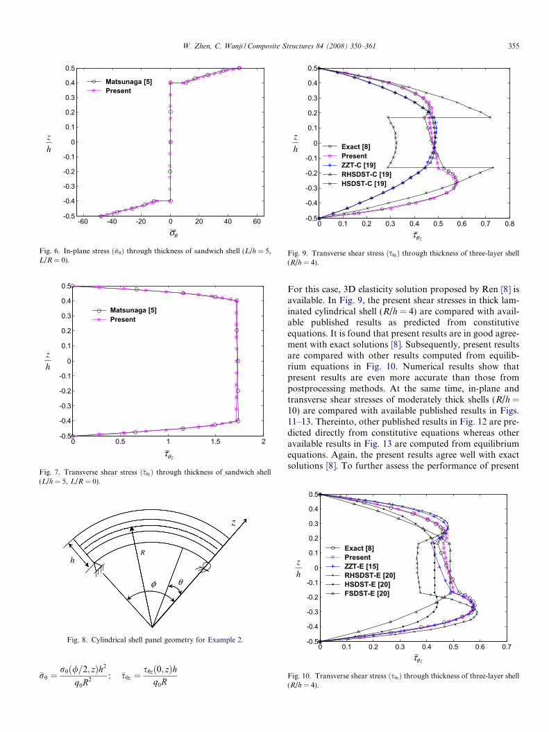
Example 2. Cylindrical bending of laminated cylindricalshell panel.
Simply supported laminated shell panel under sinusoidalloading distribution q = q0 sin (ph//) is analyzed, where /= p/3(see Fig. 8). Material constants are chosen as follows:
EL ¼ 25� 106 psi; ET ¼ 106 psi;
GLT ¼ 0:5� 106 psi; GTT ¼ 0:2� 106 psi;
vLT ¼ vTT ¼ 0:25
where subscript L is the direction parallel to the fibers andsubscript T indicates the transverse direction. In-plane andtransverse shear stresses are normalized as follows:
-60 -40 -20 0 20 40 60-0.5
-0.4
-0.3
-0.2
-0.1
0
0.1
0.2
0.3
0.4
0.5
Matsunaga [5]Present
h
z
θσ
Fig. 6. In-plane stress ð�rhÞ through thickness of sandwich shell (L/h = 5,L/R = 0).
0 0.5 1 1.5 2-0.5
-0.4
-0.3
-0.2
-0.1
0
0.1
0.2
0.3
0.4
0.5
Matsunaga [5]Present
zθτ
h
z
Fig. 7. Transverse shear stress ð�shzÞ through thickness of sandwich shell(L/h = 5, L/R = 0).
θ
Rh
φ
z
Fig. 8. Cylindrical shell panel geometry for Example 2.
0 0.1 0.2 0.3 0.4 0.5 0.6 0.7 0.8-0.5
-0.4
-0.3
-0.2
-0.1
0
0.1
0.2
0.3
0.4
0.5
Exact [8]PresentZZT-C [19]RHSDST-C [19]HSDST-C [19]
h
z
zθτ
Fig. 9. Transverse shear stress ð�shzÞ through thickness of three-layer shell(R/h = 4).
0 0.1 0.2 0.3 0.4 0.5 0.6 0.7-0.5
-0.4
-0.3
-0.2
-0.1
0
0.1
0.2
0.3
0.4
0.5
Exact [8]PresentZZT-E [15]RHSDST-E [20]HSDST-E [20]FSDST-E [20]
zθτ
h
z
Fig. 10. Transverse shear stress ð�shzÞ through thickness of three-layer shell(R/h = 4).
W. Zhen, C. Wanji / Composite Structures 84 (2008) 350–361 355
�rh ¼rhð/=2; zÞh2
q0R2; �shz ¼
shzð0; zÞhq0R
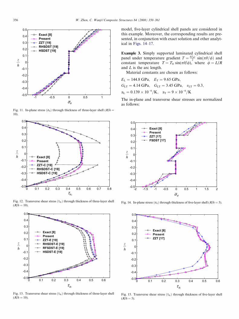
For this case, 3D elasticity solution proposed by Ren [8] isavailable. In Fig. 9, the present shear stresses in thick lam-inated cylindrical shell (R/h = 4) are compared with avail-able published results as predicted from constitutiveequations. It is found that present results are in good agree-ment with exact solutions [8]. Subsequently, present resultsare compared with other results computed from equilib-rium equations in Fig. 10. Numerical results show thatpresent results are even more accurate than those frompostprocessing methods. At the same time, in-plane andtransverse shear stresses of moderately thick shells (R/h =10) are compared with available published results in Figs.11–13. Thereinto, other published results in Fig. 12 are pre-dicted directly from constitutive equations whereas otheravailable results in Fig. 13 are computed from equilibriumequations. Again, the present results agree well with exactsolutions [8]. To further assess the performance of present
0 0.1 0.2 0.3 0.4 0.5 0.6 0.7 0.8-0.5
-0.4
-0.3
-0.2
-0.1
0
0.1
0.2
0.3
0.4
0.5
Exact [8]PresentZZT-C [19]RHSDST-C [19]HSDST-C [19]
h
z
zθτ
Fig. 12. Transverse shear stress ð�shzÞ through thickness of three-layer shell(R/h = 10).
0 0.1 0.2 0.3 0.4 0.5 0.6-0.5
-0.4
-0.3
-0.2
-0.1
0
0.1
0.2
0.3
0.4
0.5
Exact [8]PresentZZT-E [19]RHSDST-E [19]RFSDST-E [19]HSDST-E [19]
θzτ
h
z
Fig. 13. Transverse shear stress ð�shzÞ through thickness of three-layer shell(R/h = 10).
-1 -0.5 0 0.5 1-0.5
-0.4
-0.3
-0.2
-0.1
0
0.1
0.2
0.3
0.4
0.5Exact [8]PresentZZT [19] RHSDST [19]HSDST [19]
θσ
h
z
Fig. 11. In-plane stress ð�rhÞ through thickness of three-layer shell (R/h =10).
356 W. Zhen, C. Wanji / Composite Structures 84 (2008) 350–361
model, five-layer cylindrical shell panels are considered inthis example. Moreover, the corresponding results are pre-sented, in conjunction with exact solution and other analyt-ical in Figs. 14–17.
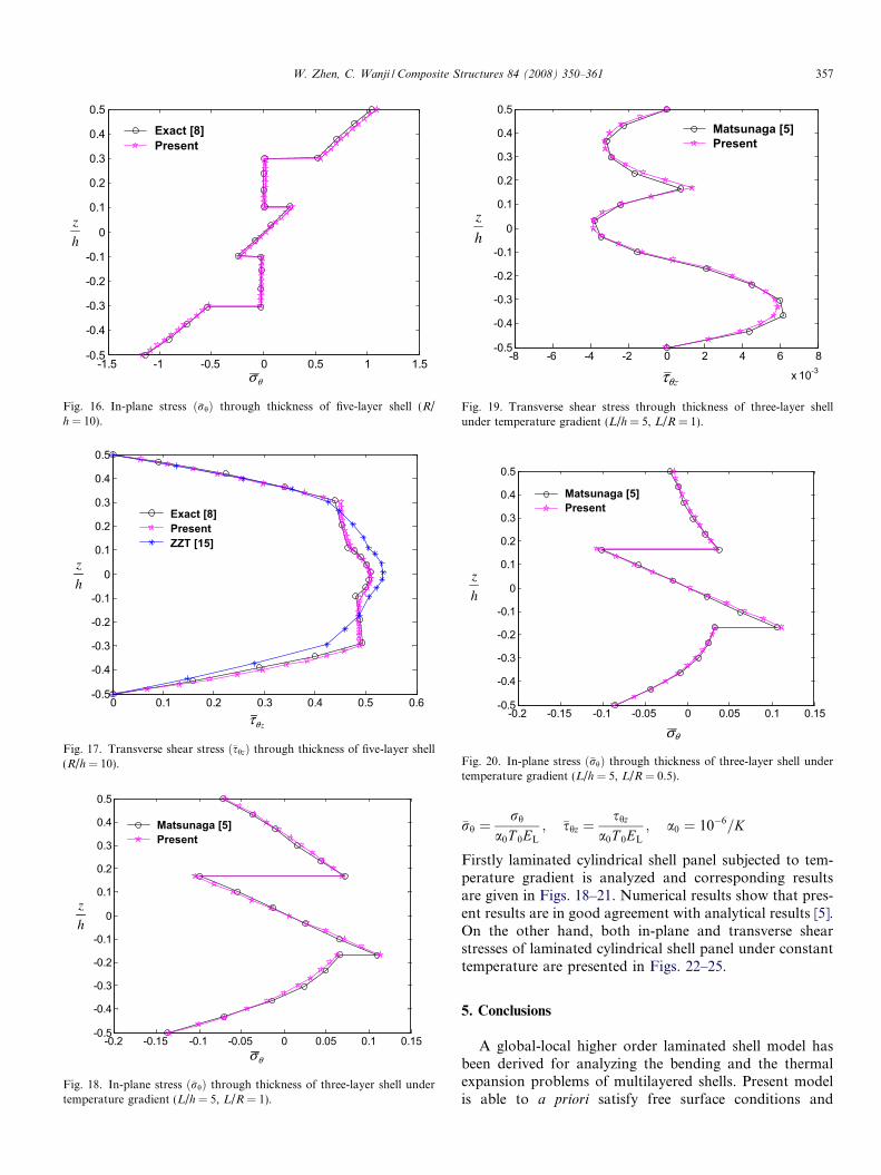
Example 3. Simply supported laminated cylindrical shellpanel under temperature gradient T ¼ hT 0z
2sinðph=/Þ and
constant temperature T = T0 sin(ph//), where / = L/Rand L is the arc length.
Material constants are chosen as follows:
EL ¼ 144:8 GPa; ET ¼ 9:65 GPa;
GLT ¼ 4:14 GPa; GLT ¼ 3:45 GPa; vLT ¼ 0:3;
aL ¼ 0:139� 10�6=K; aT ¼ 9� 10�6=K
The in-plane and transverse shear stresses are normalizedas follows:
-2 -1.5 -1 -0.5 0 0.5 1 1.5 2-0.5
-0.4
-0.3
-0.2
-0.1
0
0.1
0.2
0.3
0.4
0.5
Exact [8]PresentZZT [17]FSDST [17]
θσ
h
z
Fig. 14. In-plane stress ð�rhÞ through thickness of five-layer shell (R/h = 5).
0 0.1 0.2 0.3 0.4 0.5 0.6-0.5
-0.4
-0.3
-0.2
-0.1
0
0.1
0.2
0.3
0.4
0.5
Exact [8]PresentZZT [17]
h
z
zθτ
Fig. 15. Transverse shear stress ð�shzÞ through thickness of five-layer shell(R/h = 5).
-1.5 -1 -0.5 0 0.5 1 1.5-0.5
-0.4
-0.3
-0.2
-0.1
0
0.1
0.2
0.3
0.4
0.5
Exact [8]Present
θσ
h
z
Fig. 16. In-plane stress ð�rhÞ through thickness of five-layer shell (R/h = 10).
0 0.1 0.2 0.3 0.4 0.5 0.6-0.5
-0.4
-0.3
-0.2
-0.1
0
0.1
0.2
0.3
0.4
0.5
Exact [8]PresentZZT [15]
zθτ
h
z
Fig. 17. Transverse shear stress ð�shzÞ through thickness of five-layer shell(R/h = 10).
-0.2 -0.15 -0.1 -0.05 0 0.05 0.1 0.15-0.5
-0.4
-0.3
-0.2
-0.1
0
0.1
0.2
0.3
0.4
0.5
Matsunaga [5]Present
h
z
θσ
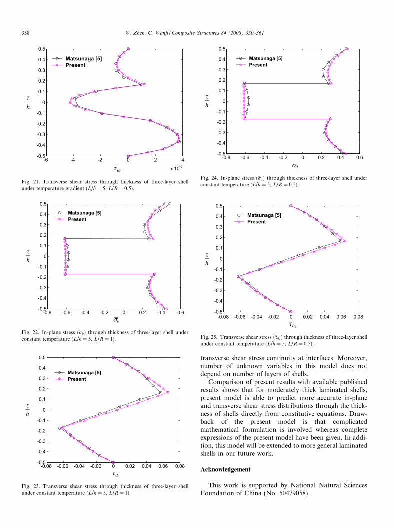
Fig. 18. In-plane stress ð�rhÞ through thickness of three-layer shell undertemperature gradient (L/h = 5, L/R = 1).
-8 -6 -4 -2 0 2 4 6 8
x 10-3
-0.5
-0.4
-0.3
-0.2
-0.1
0
0.1
0.2
0.3
0.4
0.5
Matsunaga [5]Present
θzτ
h
z
Fig. 19. Transverse shear stress through thickness of three-layer shellunder temperature gradient (L/h = 5, L/R = 1).
-0.2 -0.15 -0.1 -0.05 0 0.05 0.1 0.15-0.5
-0.4
-0.3
-0.2
-0.1
0
0.1
0.2
0.3
0.4
0.5
Matsunaga [5]Present
θσ
h
z
Fig. 20. In-plane stress ð�rhÞ through thickness of three-layer shell undertemperature gradient (L/h = 5, L/R = 0.5).
W. Zhen, C. Wanji / Composite Structures 84 (2008) 350–361 357
�rh ¼rh
a0T 0EL
; �shz ¼shz
a0T 0EL
; a0 ¼ 10�6=K
Firstly laminated cylindrical shell panel subjected to tem-perature gradient is analyzed and corresponding resultsare given in Figs. 18–21. Numerical results show that pres-ent results are in good agreement with analytical results [5].On the other hand, both in-plane and transverse shearstresses of laminated cylindrical shell panel under constanttemperature are presented in Figs. 22–25.
5. Conclusions
A global-local higher order laminated shell model hasbeen derived for analyzing the bending and the thermalexpansion problems of multilayered shells. Present modelis able to a priori satisfy free surface conditions and
h
z
-6 -4 -2 0 2 4
x 10-3
-0.5
-0.4
-0.3
-0.2
-0.1
0
0.1
0.2
0.3
0.4
0.5
Matsunaga [5]Present
θzτ
Fig. 21. Transverse shear stress through thickness of three-layer shellunder temperature gradient (L/h = 5, L/R = 0.5).
-0.8 -0.6 -0.4 -0.2 0 0.2 0.4 0.6-0.5
-0.4
-0.3
-0.2
-0.1
0
0.1
0.2
0.3
0.4
0.5
Matsunaga [5]Present
θσ
h
z
Fig. 22. In-plane stress ð�rhÞ through thickness of three-layer shell underconstant temperature (L/h = 5, L/R = 1).
-0.08 -0.06 -0.04 -0.02 0 0.02 0.04 0.06 0.08-0.5
-0.4
-0.3
-0.2
-0.1
0
0.1
0.2
0.3
0.4
0.5
Matsunaga [5]Present
zθτ
h
z
Fig. 23. Transverse shear stress through thickness of three-layer shellunder constant temperature (L/h = 5, L/R = 1).
-0.8 -0.6 -0.4 -0.2 0 0.2 0.4 0.6-0.5
-0.4
-0.3
-0.2
-0.1
0
0.1
0.2
0.3
0.4
0.5
Matsunaga [5]Present
h
z
θσ
Fig. 24. In-plane stress ð�rhÞ through thickness of three-layer shell underconstant temperature (L/h = 5, L/R = 0.5).
-0.08 -0.06 -0.04 -0.02 0 0.02 0.04 0.06 0.08-0.5
-0.4
-0.3
-0.2
-0.1
0
0.1
0.2
0.3
0.4
0.5
Matsunaga [5]Present
h
z
zθτ
Fig. 25. Transverse shear stress ð�shzÞ through thickness of three-layer shellunder constant temperature (L/h = 5, L/R = 0.5).
358 W. Zhen, C. Wanji / Composite Structures 84 (2008) 350–361
transverse shear stress continuity at interfaces. Moreover,number of unknown variables in this model does notdepend on number of layers of shells.
Comparison of present results with available publishedresults shows that for moderately thick laminated shells,present model is able to predict more accurate in-planeand transverse shear stress distributions through the thick-ness of shells directly from constitutive equations. Draw-back of the present model is that complicatedmathematical formulation is involved whereas completeexpressions of the present model have been given. In addi-tion, this model will be extended to more general laminatedshells in our future work.
Acknowledgement
This work is supported by National Natural SciencesFoundation of China (No. 50479058).
W. Zhen, C. Wanji / Composite Structures 84 (2008) 350–361 359
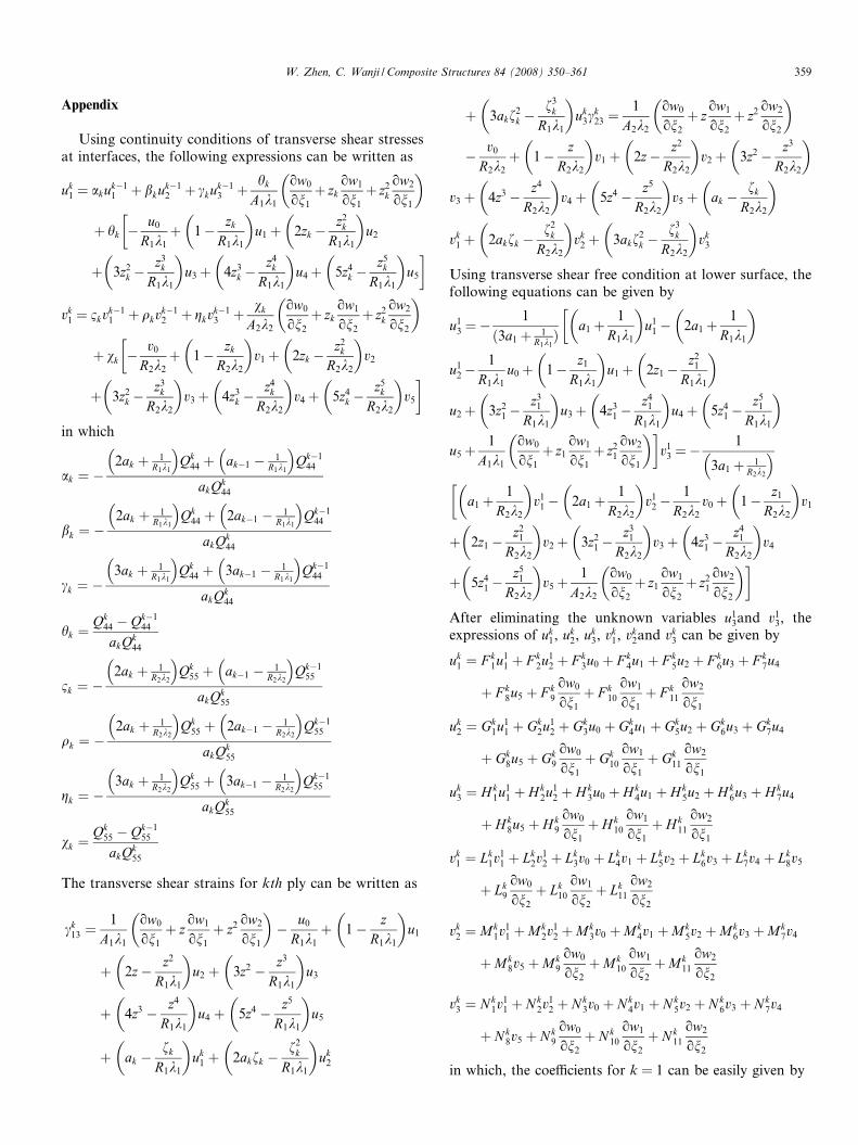
Appendix
Using continuity conditions of transverse shear stressesat interfaces, the following expressions can be written as
uk1 ¼ akuk�1
1 þ bkuk�12 þ ckuk�1
3 þ hk
A1k1
ow0
on1
þ zkow1
on1
þ z2k
ow2
on1
� �
þ hk �u0
R1k1
þ 1� zk
R1k1
� �u1 þ 2zk �
z2k
R1k1
� �u2
�
þ 3z2k �
z3k
R1k1
� �u3þ 4z3
k �z4
k
R1k1
� �u4þ 5z4
k �z5
k
R1k1
� �u5
�
vk1 ¼ 1kvk�1
1 þ qkvk�12 þ gkvk�1
3 þ vk
A2k2
ow0
on2
þ zkow1
on2
þ z2k
ow2
on2
� �
þ vk �v0
R2k2
þ 1� zk
R2k2
� �v1 þ 2zk �
z2k
R2k2
� �v2
�
þ 3z2k �
z3k
R2k2
� �v3þ 4z3
k �z4
k
R2k2
� �v4þ 5z4
k �z5
k
R2k2
� �v5
�
in which
ak ¼ �2ak þ 1
R1k1
� Qk
44 þ ak�1 � 1R1k1
� Qk�1
44
akQk44
bk ¼ �2ak þ 1
R1k1
� Qk
44 þ 2ak�1 � 1R1k1
� Qk�1
44
akQk44
ck ¼ �3ak þ 1
R1k1
� Qk
44 þ 3ak�1 � 1R1k1
� Qk�1
44
akQk44
hk ¼Qk
44 � Qk�144
akQk44
1k ¼ �2ak þ 1
R2k2
� Qk
55 þ ak�1 � 1R2k2
� Qk�1
55
akQk55
qk ¼ �2ak þ 1
R2k2
� Qk
55 þ 2ak�1 � 1R2k2
� Qk�1
55
akQk55
gk ¼ �3ak þ 1
R2k2
� Qk
55 þ 3ak�1 � 1R2k2
� Qk�1
55
akQk55
vk ¼Qk
55 � Qk�155
akQk55
The transverse shear strains for kth ply can be written as
ck13 ¼
1
A1k1
ow0
on1
þ zow1
on1
þ z2 ow2
on1
� �� u0
R1k1
þ 1� zR1k1
� �u1
þ 2z� z2
R1k1
� �u2 þ 3z2 � z3
R1k1
� �u3
þ 4z3 � z4
R1k1
� �u4 þ 5z4 � z5
R1k1
� �u5
þ ak �fk
R1k1
� �uk
1 þ 2akfk �f2
k
R1k1
� �uk
2
þ 3akf2k �
f3k
R1k1
� �uk
3ck23 ¼
1
A2k2
ow0
on2
þ zow1
on2
þ z2 ow2
on2
� �
� v0
R2k2
þ 1� zR2k2
� �v1 þ 2z� z2
R2k2
� �v2 þ 3z2 � z3
R2k2
� �
v3 þ 4z3 � z4
R2k2
� �v4 þ 5z4 � z5
R2k2
� �v5 þ ak �
fk
R2k2
� �
vk1 þ 2akfk �
f2k
R2k2
� �vk
2 þ 3akf2k �
f3k
R2k2
� �vk
3
Using transverse shear free condition at lower surface, thefollowing equations can be given by
u13 ¼�
1
ð3a1þ 1R1k1Þ a1 þ
1
R1k1
� �u1
1 � 2a1þ1
R1k1
� ��
u12�
1
R1k1
u0þ 1� z1
R1k1
� �u1þ 2z1�
z21
R1k1
� �
u2þ 3z21�
z31
R1k1
� �u3þ 4z3
1�z4
1
R1k1
� �u4 þ 5z4
1�z5
1
R1k1
� �
u5þ1
A1k1
ow0
on1
þ z1
ow1
on1
þ z21
ow2
on1
� ��v1
3 ¼�1
3a1þ 1R2k2
� a1þ
1
R2k2
� �v1
1� 2a1 þ1
R2k2
� �v1
2�1
R2k2
v0þ 1� z1
R2k2
� �v1
�
þ 2z1�z2
1
R2k2
� �v2þ 3z2
1�z3
1
R2k2
� �v3þ 4z3
1 �z4
1
R2k2
� �v4
þ 5z41�
z51
R2k2
� �v5þ
1
A2k2
ow0
on2
þ z1
ow1
on2
þ z21
ow2
on2
� ��
After eliminating the unknown variables u13and v1
3, theexpressions of uk
1, uk2, uk
3, vk1, vk
2and vk3 can be given by
uk1 ¼ F k
1u11 þ F k
2u12 þ F k
3u0 þ F k4u1 þ F k
5u2 þ F k6u3 þ F k
7u4
þ F k8u5 þ F k
9
ow0
on1
þ F k10
ow1
on1
þ F k11
ow2
on1
uk2 ¼ Gk
1u11 þ Gk
2u12 þ Gk
3u0 þ Gk4u1 þ Gk
5u2 þ Gk6u3 þ Gk
7u4
þ Gk8u5 þ Gk
9
ow0
on1
þ Gk10
ow1
on1
þ Gk11
ow2
on1
uk3 ¼ H k
1u11 þ Hk
2u12 þ H k
3u0 þ H k4u1 þ Hk
5u2 þ H k6u3 þ Hk
7u4
þ Hk8u5 þ H k
9
ow0
on1
þ H k10
ow1
on1
þ Hk11
ow2
on1
vk1 ¼ Lk
1v11 þ Lk
2v12 þ Lk
3v0 þ Lk4v1 þ Lk
5v2 þ Lk6v3 þ Lk
7v4 þ Lk8v5
þ Lk9
ow0
on2
þ Lk10
ow1
on2
þ Lk11
ow2
on2
vk2 ¼ Mk
1v11 þMk
2v12 þMk
3v0 þMk4v1 þMk
5v2 þMk6v3 þMk
7v4
þMk8v5 þMk
9
ow0
on2
þMk10
ow1
on2
þMk11
ow2
on2
vk3 ¼ N k
1v11 þ N k
2v12 þ Nk
3v0 þ Nk4v1 þ N k
5v2 þ N k6v3 þ Nk
7v4
þ Nk8v5 þ N k
9
ow0
on2
þ N k10
ow1
on2
þ N k11
ow2
on2
in which, the coefficients for k = 1 can be easily given by
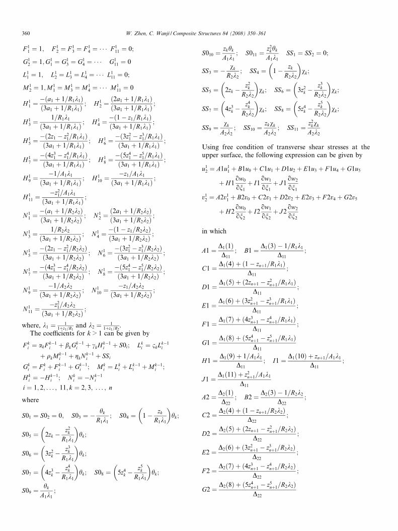
360 W. Zhen, C. Wanji / Composite Structures 84 (2008) 350–361
F 11 ¼ 1; F 1
2 ¼ F 13 ¼ F 1
4 ¼ � � � F 111 ¼ 0;
G12 ¼ 1;G1
1 ¼ G13 ¼ G1
4 ¼ � � � G111 ¼ 0
L11 ¼ 1; L1
2 ¼ L13 ¼ L1
4 ¼ � � � L111 ¼ 0;
M12 ¼ 1;M1
1 ¼ M13 ¼ M1
4 ¼ � � � M111 ¼ 0
H 11 ¼�ða1 þ 1=R1k1Þð3a1 þ 1=R1k1Þ
; H 12 ¼ð2a1 þ 1=R1k1Þð3a1 þ 1=R1k1Þ
;
H 13 ¼
1=R1k1
ð3a1 þ 1=R1k1Þ; H 1
4 ¼�ð1� z1=R1k1Þð3a1 þ 1=R1k1Þ
;
H 15 ¼�ð2z1 � z2
1=R1k1Þð3a1 þ 1=R1k1Þ
; H 16 ¼�ð3z2
1 � z31=R1k1Þ
ð3a1 þ 1=R1k1Þ;
H 17 ¼�ð4z3
1 � z41=R1k1Þ
ð3a1 þ 1=R1k1Þ; H 1
8 ¼�ð5z4
1 � z51=R1k1Þ
ð3a1 þ 1=R1k1Þ;
H 19 ¼
�1=A1k1
ð3a1 þ 1=R1k1Þ; H 1
10 ¼�z1=A1k1
ð3a1 þ 1=R1k1Þ;
H 111 ¼
�z21=A1k1
ð3a1 þ 1=R1k1Þ;
N 11 ¼�ða1 þ 1=R2k2Þð3a1 þ 1=R2k2Þ
; N 12 ¼ð2a1 þ 1=R2k2Þð3a1 þ 1=R2k2Þ
;
N 13 ¼
1=R2k2
ð3a1 þ 1=R2k2Þ; N 1
4 ¼�ð1� z1=R2k2Þð3a1 þ 1=R2k2Þ
;
N 15 ¼�ð2z1 � z2
1=R2k2Þð3a1 þ 1=R2k2Þ
; N 16 ¼�ð3z2
1 � z31=R2k2Þ
ð3a1 þ 1=R2k2Þ;
N 17 ¼�ð4z3
1 � z41=R2k2Þ
ð3a1 þ 1=R2k2Þ; N 1
8 ¼�ð5z4
1 � z51=R2k2Þ
ð3a1 þ 1=R2k2Þ;
N 19 ¼
�1=A2k2
ð3a1 þ 1=R2k2Þ; N 1
10 ¼�z1=A2k2
ð3a1 þ 1=R2k2Þ;
N 111 ¼
�z21=A2k2
ð3a1 þ 1=R2k2Þ;
where, k1 ¼ 11þz1=R1
and k2 ¼ 11þz1=R2
.The coefficients for k > 1 can be given by
F ki ¼ akF k�1
i þ bkGk�1i þ ckHk�1
i þ S0i; Lki ¼ 1kLk�1
i
þ qkMk�1i þ gkN k�1
i þ SSi
Gki ¼ F k
i þ F k�1i þ Gk�1
i ; Mki ¼ Lk
i þ Lk�1i þMk�1
i ;
H ki ¼ �Hk�1
i ; Nki ¼ �Nk�1
i
i ¼ 1; 2; . . . ; 11; k ¼ 2; 3; . . . ; n
where
S01 ¼ S02 ¼ 0; S03 ¼ �hk
R1k1
; S04 ¼ 1� zk
R1k1
� �hk;
S05 ¼ 2zk �z2
k
R1k1
� �hk;
S06 ¼ 3z2k �
z3k
R1k1
� �hk;
S07 ¼ 4z3k �
z4k
R1k1
� �hk; S08 ¼ 5z4
k �z5
k
R1k1
� �hk;
S09 ¼hk
A1k1
;
S010 ¼zkhk
A1k1
; S011 ¼z2
khk
A1k1
SS1 ¼ SS2 ¼ 0;
SS3 ¼ �vk
R2k2
; SS4 ¼ 1� zk
R2k2
� �vk;
SS5 ¼ 2zk �z2
k
R2k2
� �vk; SS6 ¼ 3z2
k �z3
k
R2k2
� �vk;
SS7 ¼ 4z3k �
z4k
R2k2
� �vk; SS8 ¼ 5z4
k �z5
k
R2k2
� �vk;
SS9 ¼vk
A2k2
; SS10 ¼zkvk
A2k2
; SS11 ¼z2
kvk
A2k2
Using free condition of transverse shear stresses at theupper surface, the following expression can be given by
u12 ¼ A1u1
1 þ B1u0 þ C1u1 þ D1u2 þ E1u3 þ F 1u4 þ G1u5
þ H1ow0
on1
þ I1ow1
on1
þ J1ow2
on1
v12 ¼ A2v1
1 þ B2v0 þ C2v1 þ D2v2 þ E2v3 þ F 2v4 þ G2v5
þ H2ow0
on2
þ I2ow1
on2
þ J2ow2
on2
in which
A1 ¼ D1ð1ÞD11
; B1 ¼ D1ð3Þ � 1=R1k1
D11
;
C1 ¼ D1ð4Þ þ ð1� znþ1=R1k1ÞD11
;
D1 ¼D1ð5Þ þ ð2znþ1 � z2
nþ1=R1k1ÞD11
;
E1 ¼D1ð6Þ þ ð3z2
nþ1 � z3nþ1=R1k1Þ
D11
;
F 1 ¼D1ð7Þ þ ð4z3
nþ1 � z4nþ1=R1k1Þ
D11
;
G1 ¼ D1ð8Þ þ ð5z4nþ1 � z5
nþ1=R1k1ÞD11
H1 ¼ D1ð9Þ þ 1=A1k1
D11
; I1 ¼ D1ð10Þ þ znþ1=A1k1
D11
;
J1 ¼ D1ð11Þ þ z2nþ1=A1k1
D11
A2 ¼ D2ð1ÞD22
; B2 ¼ D2ð3Þ � 1=R2k2
D22
;
C2 ¼ D2ð4Þ þ ð1� znþ1=R2k2ÞD22
;
D2 ¼D2ð5Þ þ ð2znþ1 � z2
nþ1=R2k2ÞD22
;
E2 ¼D2ð6Þ þ ð3z2
nþ1 � z3nþ1=R2k2Þ
D22
;
F 2 ¼D2ð7Þ þ ð4z3
nþ1 � z4nþ1=R2k2Þ
D22
;
G2 ¼D2ð8Þ þ ð5z4
nþ1 � z5nþ1=R2k2Þ
D22
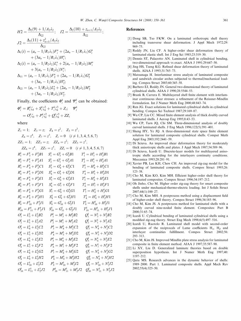
W. Zhen, C. Wanji / Composite Structures 84 (2008) 350–361 361
H2 ¼ D2ð9Þ þ 1=A2k2
D22
; I2 ¼ D2ð10Þ þ znþ1=A2k2
D22
;
J2 ¼ D2ð11Þ þ z2nþ1=A2k2
D22
D1ðiÞ ¼ ðan � 1=R1k1ÞF ni þ ð2an � 1=R1k1ÞGn
i
þ ð3an � 1=R1k1ÞH ni ;
D2ðiÞ ¼ ðan � 1=R2k2ÞLni þ 2ðan � 1=R2k2ÞMn
i
þ 3ðan � 1=R2k2ÞNni ;
D11 ¼ ðan � 1=R1k1ÞF n2 þ ð2an � 1=R1k1ÞGn
2
þ ð3an � 1=R1k1ÞH n2;
D22 ¼ ðan � 1=R2k2ÞLn2 þ ð2an � 1=R2k2ÞMn
2
þ ð3an � 1=R2k2ÞNn2:
Finally, the coefficients Uki and Wk
i can be obtained:
Uki ¼ Rk
i fk þ Ski f
2k þ T k
i f3k þ Zi; Wk
i
¼ Oki fk þ P k
i f2k þ Qk
i f3k þ ZZi
where
Z1 ¼ 1; Z3 ¼ z; Z4 ¼ z2; Z5 ¼ z3;
Z6 ¼ z4; Z7 ¼ z5; Zi ¼ 0 ði 6¼ 1; 3; 4; 5; 6; 7ÞZZ1 ¼ 1; ZZ3 ¼ z; ZZ4 ¼ z2; ZZ5 ¼ z3;
ZZ6 ¼ z4; ZZ7 ¼ z5; ZZi ¼ 0 ði 6¼ 1; 3; 4; 5; 6; 7ÞRk
1 ¼ F k3 þ F k
2B1 Sk1 ¼ Gk
3 þ Gk2B1 T k
1 ¼ Hk3 þ Hk
2B1
Rk2 ¼ F k
1 þ F k2A1 Sk
2 ¼ Gk1 þ Gk
2A1 T k2 ¼ Hk
1 þ Hk2A1
Rk3 ¼ F k
4 þ F k2C1 Sk
3 ¼ Gk4 þ Gk
2C1 T k3 ¼ Hk
4 þ Hk2C1
Rk4 ¼ F k
5 þ F k2D1 Sk
4 ¼ Gk5 þ Gk
2D1 T k4 ¼ Hk
5 þ Hk2D1
Rk5 ¼ F k
6 þ F k2E1 Sk
5 ¼ Gk6 þ Gk
2E1 T k5 ¼ Hk
6 þ Hk2E1
Rk6 ¼ F k
7 þ F k2F 1 Sk
6 ¼ Gk7 þ Gk
2F 1 T k6 ¼ H k
7 þ H k2F 1
Rk7 ¼ F k
8 þ F k2G1 Sk
7 ¼ Gk8 þ Gk
2G1 T k7 ¼ H k
8 þ Hk2G1
Rk8 ¼ F k
9 þ F k2H1 Sk
8 ¼ Gk9 þ Gk
2H1 T k8 ¼ Hk
9 þ Hk2H1
Rk9 ¼ F k
10 þ F k2I1 Sk
9 ¼ Gk10 þ Gk
2I1 T k9 ¼ Hk
10 þ Hk2I1
Rk10 ¼ F k
11 þ F k2J1 Sk
10 ¼ Gk11 þ Gk
2J1 T k10 ¼ Hk
11 þ Hk2J1
Ok1 ¼ Lk
3 þ Lk2B2 P k
1 ¼ Mk3 þMk
2B2 Qk1 ¼ N k
3 þ Nk2B2
Ok2 ¼ Lk
1 þ Lk2A2 P k
2 ¼ Mk1 þMk
2A2 Qk2 ¼ N k
1 þ Nk2A2
Ok3 ¼ Lk
4 þ Lk2C2 P k
3 ¼ Mk4 þMk
2C2 Qk3 ¼ Nk
4 þ N k2C2
Ok4 ¼ Lk
5 þ Lk2D2 P k
4 ¼ Mk5 þMk
2D2 Qk4 ¼ N k
5 þ N k2D2
Ok5 ¼ Lk
6 þ Lk2E2 P k
5 ¼ Mk6 þMk
2E2 Qk5 ¼ N k
6 þ N k2E2
Ok6 ¼ Lk
7 þ Lk2F 2 P k
6 ¼ Mk7 þMk
2F 2 Qk6 ¼ N k
7 þ N k2F 2
Ok7 ¼ Lk
8 þ Lk2G2 P k
7 ¼ Mk8 þMk
2G2 Qk7 ¼ N k
8 þ N k2G2
Ok8 ¼ Lk
9 þ Lk2H2 P k
8 ¼ Mk9 þMk
2H2 Qk8 ¼ N k
9 þ N k2H2
Ok9 ¼ Lk
10 þ Lk2I2 P k
9 ¼ Mk10 þMk
2I2 Qk9 ¼ Nk
10 þ N k2I2
Ok10 ¼ Lk
11 þ Lk2J2 P k
10 ¼ Mk11 þMk
2J2 Qk10 ¼ N k
11 þ N k2J2
References
[1] Dong SB, Tso FKW. On a laminated orthotropic shell theoryincluding transverse shear deformation. J Appl Mech 1972;29:969–75.
[2] Reddy JN, Liu CF. A higher-order shear deformation theory oflaminated elastic shell. Int J Eng Sci 1985;23:319–30.
[3] Dennis ST, Palazotto AN. Laminated shell in cylindrical bending,two-dimensional approach vs exact. AIAA J 1991;29:647–50.
[4] Jing HS, Tzeng KG. Refined shear deformation theory of laminatedshells. AIAA J 1993;31:765–73.
[5] Matsunaga H. Interlaminar stress analysis of laminated compositeand sandwich circular arches subjected to thermal/mechanical load-ing. Compos Struct 2003;60:345–58.
[6] Barbero EJ, Reddy JN. General two-dimensional theory of laminatedcylindrical shells. AIAA J 1990;28:5544–53.
[7] Brank B, Carrera E. Multilayered shell finite element with interlam-inar continuous shear stresses: a refinement of the Reissner-Mindlinformulation. Int J Numer Meth Eng 2000;48:843–74.
[8] Ren JG. Exact solutions for laminated cylindrical shells in cylindricalbending. Compos Sci Technol 1987;29:169–87.
[9] Wu CP, Liu CC. Mixed finite element analysis of thick doubly curvedlaminated shells. J Aerosp Eng 1995;8:43–53.
[10] Wu CP, Tarn JQ, Chi SM. Three-dimensional analysis of doublycurved laminated shells. J Eng Mech 1996;122(5):391–401.
[11] Sheng HY, Ye JQ. A three-dimensional state space finite elementsolution for laminated composite cylindrical shells. Comput MethAppl Eng 2003;192:2441–59.
[12] Di Sciuva. An improved shear deformation theory for moderatelythick anisotropic shells and plates. J Appl Mech 1987;54:589–96.
[13] Di Sciuva, Icardi U. Discrete-layer models for multilayered aniso-tropic shells according for the interlayers continuity conditions.Meccanica 1993;28:281–91.
[14] Xavier PB, Lee KH, Chew CH. An improved zig-zag model for thebending of laminated composite shells. Compos Struct 1993;26:123–38.
[15] Cho M, Kim KO, Kim MH. Efficient higher-order shell theory forlaminated composites. Compos Struct 1996;34:197–212.
[16] Oh Jinho, Cho M. Higher order zig-zag theory for smart compositeshells under mechanical-thermo-electric loading. Int J Solids Struct2007;44(1):100–27.
[17] Cho M, Kim MH. A postprocess method using a displacement fieldof higher-order shell theory. Compos Struct 1996;34:185–96.
[18] Cho M, Kim JS. A postprocess method for laminated shells with adoubly curved nine-noded finite element. Composites: Part B2000;31:65–74.
[19] Icardi U. Cylindrical bending of laminated cylindrical shells using amodified zig-zag theory. Struct Eng Mech 1998;6(5):497–516.
[20] Icardi U, Ruotolo R. Laminated shell model with second-orderexpansion of the reciprocals of Lame coefficients Ha, Hb andinterlayer continuities fulfillment. Compos Struct 2002;56:293–313.
[21] Cho M, Kim JS. Improved Mindlin plate stress analysis for laminatedcomposite in finite element method. AIAA J 1997;35:587–90.
[22] Li XY, Liu D. Generalized laminate theories based on doublesuperposition hypothesis. Int J Numer Meth Eng 1997;40:1197–212.
[23] Qatu MS. Research advances in the dynamic behavior of shells:1989–2000. Part 1. Laminated composite shells. Appl Mech Rev2002;55(4):325–50.