Embed Size (px)
Citation preview

A Gentle Introduction to
Model Predictive Control (MPC) Formulations
based on
Discrete Linear State Space Models
Sachin C. Patwardhan
Professor, Dept. of Chemical Engineering,
I. I. T. Bombay, Powai, Mumbai 400 076
Email: [email protected]
Contents
1 Introduction 2
2 Dynamic Model for Controller Synthesis 32.1 Linearization of First Principles / Grey Box Model . . . . . . . . . . . . . . . . 4
2.2 State Realization of Time Series Model . . . . . . . . . . . . . . . . . . . . . . . 5
3 Quadratic Optimal Control 53.1 Linear Quadratic Optimal State Regulator Design . . . . . . . . . . . . . . . . . 6
3.2 Linear Quadratic Optimal Output Regulator Design . . . . . . . . . . . . . . . . 9
3.3 Stability of LQ controller . . . . . . . . . . . . . . . . . . . . . . . . . . . . . . . 10
3.4 Linear Quadratic Gaussian (LQG) Control . . . . . . . . . . . . . . . . . . . . . 11
3.4.1 State Estimation . . . . . . . . . . . . . . . . . . . . . . . . . . . . . . . 11
3.4.2 Separation Principle and Nominal Closed Loop Stability . . . . . . . . . 13
3.5 Tracking and Regulation using Quadratic Optimal Controller . . . . . . . . . . . 14
3.5.1 Model Transformation for Output Regulation and Tracking . . . . . . . . 15
3.5.2 Dealing with Unmeasured Disturbances and Model Plant Mismatch . . . 17
1

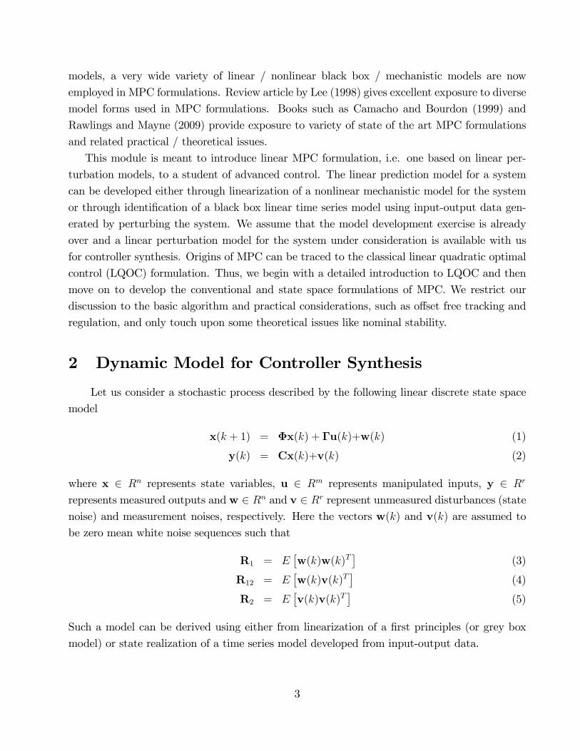
4 Model Predictive Control 224.1 Model Based Prediction of Future Behavior . . . . . . . . . . . . . . . . . . . . 23
4.1.1 Innovation Bias Approach . . . . . . . . . . . . . . . . . . . . . . . . . . 24
4.1.2 State Augmentation Approach . . . . . . . . . . . . . . . . . . . . . . . . 26
4.2 Conventional Formulation of MPC . . . . . . . . . . . . . . . . . . . . . . . . . 27
4.2.1 Tuning Parameters . . . . . . . . . . . . . . . . . . . . . . . . . . . . . . 29
4.2.2 Unconstrained MPC . . . . . . . . . . . . . . . . . . . . . . . . . . . . . 31
4.2.3 QP Formulation of MPC . . . . . . . . . . . . . . . . . . . . . . . . . . . 35
4.3 State Space Formulation of MPC . . . . . . . . . . . . . . . . . . . . . . . . . . 36
4.3.1 Generation of Target States . . . . . . . . . . . . . . . . . . . . . . . . . 36
4.4 State Space Formulation of MPC . . . . . . . . . . . . . . . . . . . . . . . . . . 37
4.5 Nominal Stability (Goodwin et al., 2009) . . . . . . . . . . . . . . . . . . . . . . 38
5 Summary 40
6 References 41
1 Introduction
Model Predictive Control (MPC) schemes developed in late 70�s, such as dynamic matrix
control (DMC) or model algorithmic control (MAC), have found wide acceptance in the process
industry (Qin and Badgwell, 2003). With availability of fast computers and microprocessors,
MPC is increasingly �nding application in many other engineering domains such as robotics,
automobiles, nuclear and aerospace industries. Major strengths of MPC are abilities to handle
multivariable interactions and operating constraints in systematic manner. MPC is formulated
as a constrained optimization problem, which is solved on-line repeatedly by carrying out model
based forecasting over a moving window of time. More importantly, MPC facilitates optimal
control of non-square systems, i.e. systems with unequal number of manipulated inputs and
measured outputs.
Unlike many other control schemes, MPC originated from the industrial practitioners with
the academia stepping in later to provide backbone of theory. Excellent reviews of MPC are
available in the literature such as Garcia et al. (1989), Morari and Lee (1999) and Qin and
Badgwell (2003). Yu et al. (1994) provide a tutorial introduction to linear model based MPC
(LMPC) formulation. The seminal contribution by Muske and Rawlings (1993) connects the
LMPC with the classical state space based linear quadratic optimal control and establishes
the nominal stability using Lyapunov�s method. Dynamic models are at the heart of MPC
formulations. While initial formulations were based on �nite impulse response or step response
2
models, a very wide variety of linear / nonlinear black box / mechanistic models are now
employed in MPC formulations. Review article by Lee (1998) gives excellent exposure to diverse
model forms used in MPC formulations. Books such as Camacho and Bourdon (1999) and
Rawlings and Mayne (2009) provide exposure to variety of state of the art MPC formulations
and related practical / theoretical issues.
This module is meant to introduce linear MPC formulation, i.e. one based on linear per-
turbation models, to a student of advanced control. The linear prediction model for a system
can be developed either through linearization of a nonlinear mechanistic model for the system
or through identi�cation of a black box linear time series model using input-output data gen-
erated by perturbing the system. We assume that the model development exercise is already
over and a linear perturbation model for the system under consideration is available with us
for controller synthesis. Origins of MPC can be traced to the classical linear quadratic optimal
control (LQOC) formulation. Thus, we begin with a detailed introduction to LQOC and then
move on to develop the conventional and state space formulations of MPC. We restrict our
discussion to the basic algorithm and practical considerations, such as o¤set free tracking and
regulation, and only touch upon some theoretical issues like nominal stability.
2 Dynamic Model for Controller Synthesis
Let us consider a stochastic process described by the following linear discrete state space
model
x(k + 1) = �x(k) + �u(k)+w(k) (1)
y(k) = Cx(k)+v(k) (2)
where x 2 Rn represents state variables, u 2 Rm represents manipulated inputs, y 2 Rr
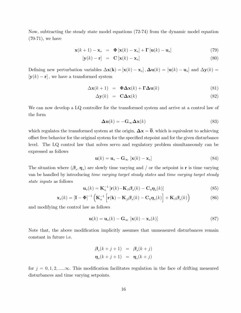
represents measured outputs and w 2 Rn and v 2 Rr represent unmeasured disturbances (statenoise) and measurement noises, respectively. Here the vectors w(k) and v(k) are assumed to
be zero mean white noise sequences such that
R1 = E�w(k)w(k)T
�(3)
R12 = E�w(k)v(k)T
�(4)
R2 = E�v(k)v(k)T
�(5)
Such a model can be derived using either from linearization of a �rst principles (or grey box
model) or state realization of a time series model developed from input-output data.
3

2.1 Linearization of First Principles / Grey Box Model
Linear discrete perturbation model of the form
x(k + 1) = �x(k) + �u(k)+�dd(k) (6)
y(k) = Cx(k)+v(k) (7)
can be developed in the neighborhood of an operating point starting from a nonlinear �rst
principles (or grey box) model. Here, d 2 Rd represents vector of (physical) unmeasured
disturbances, such as �uctuations in feed concentrations, feed �ows, feed temperature etc.,
which are assumed to be adequately represented by piecewise constant functions. If it is further
assumed that fd(k)g is a zero mean white noise sequence with known covariance matrix, sayQd; then we can de�ne state noise vector w(k) as follows
w(k) = �dd(k) (8)
E [w(k)] = 0 ; Cov [w(k)] = R1 = �dQd�Td (9)
The state and the measurement noise are assumed to be uncorrelated in this case i.e. R12 =
Cov [w(k);v(k)] is a null matrix of appropriate dimension.
When a state space model derived from �rst principles is used for inferential control, the
set of controlled outputs may di¤er from the set of measured output. Suppose we represent the
controlled outputs yr 2 Rr as follows
yr(k) = Crx(k)
then, in general, yr(k) need not be identical with y(k):
Example 1 Consider a CSTR in which the state variable vector is perturbations in reactor
concentration and reactor temperature
x =h�CA �T
iTIf reactor temperature is measured and it is desired to control reactor concentration, then
C =h0 1
iand
Cr =h1 0
iHowever, in the development that follows, we assume that the controlled output is same
as the measured output, i.e. yr(k) � y(k): Modi�cations necessary when yr(k) 6= y(k) are
relatively straightforward and are not discussed separately.
4

2.2 State Realization of Time Series Model
The innovations form of state space model of the form
x(k + 1) = �x(k) + �u(k) + Le(k) (10)
y(k) = Cx(k) + e(k) (11)
can be obtained from time series models (ARX/ARMAX/BJ) models identi�ed from input-
output data. Here, the innovations (or residuals) fe(k)g are a zero mean Gaussian white noisesequence with covariance matrix Ve and L represents the corresponding steady state Kalman
gain. The above model can be re-written as
x(k + 1) = �x(k) + �u(k) +w(k) (12)
y(k) = Cx(k) + v(k) (13)
where the vectors w(k) 2 Rnand v(k) 2 Rr are zero mean white noise sequences such that
R1 = E�w(k)w(k)T
�= LVT
e L (14)
R12 = E�w(k)v(k)T
�= LVe (15)
R2 = E�v(k)v(k)T
�= Ve (16)
It may be noted that, when a state space model is identi�ed from data, we have Cr= C, i.e.,
the set of outputs that can be controlled is identical to the set of measured outputs.
3 Quadratic Optimal Control
The above model is used as a basis for design of a state feedback controller. Steps involved in
design of any state feed-back controller are as follows
1. Solve regulator / controller design problem under the assumption that full state vector is
available for feedback
2. Design a state estimator and implement the state feedback control law using estimated
states.
For linear systems, the closed loop stability under the nominal conditions (i.e. no model
plant mismatch) is guaranteed by the separation principle.
In this section, we �rst describe the method for designing quadratic optimal state feedback
control law and later show how the control law can be implemented using an optimal state
5

observer (Kalman predictor). The separation principle is also brie�y described. While, from
a practical viewpoint, it is desirable to develop a state feedback control law which can reject
drifting unmeasured disturbances and track arbitrary setpoint changes, we begin the develop-
ment by considering a seemingly simplistic and idealized scenario i.e. regulation at the origin
of the state space using a state feedback control law. The simplifying assumptions are then
removed gradually and we move towards synthesizing a controller that achieves desired tracking
and regulation for arbitrary setpoint changes and arbitrary disturbances, respectively.
3.1 Linear Quadratic Optimal State Regulator Design
We �rst discuss the state regulator design problem, where it is desired to bring the system form
non-zero initial state to zero initial state (the origin of state space). Non-zero initial state can
result from impulse like disturbances, which are su¢ ciently spaced in time. We want to device
a state feedback regulator of type
u(k) = �Gx(k)
which will bring the system to the origin in a optimal fashion. For designing the regulator, we
only consider the deterministic part of the model, i.e.
x(k + 1) = �x(k) + �u(k) (17)
y(k) = Cx(k) (18)
The regulator design problem is posed as an optimization problem where it is desired to de-
termine control sequence u(0);u(1):::::u(N � 1) that takes the system to the origin in some
optimal manner. To achieve this goal, we need to formulate a performance objective. When
origin is the desired state and the system is at x(0) 6= 0; the prime objective is to move to
the origin as quickly as possible. This can be achieved by including a term in the performance
objective that penalizes distance from the origin
kx(k)k22 =�x(k)� 0
�T �x(k)� 0
�= x(k)Tx(k)
As individual elements of the states can have di¤erent ranges of magnitudes, it is often advan-
tageous to de�ne a weighted distance measure of the form
kx(k)k2Wx;2= x(k)TWxx(k)
whereWx is a positive de�nite matrix. Other important concern while designing any control
law is that it should not result in excessively large control moves. Also, di¤erent manipulated
inputs may have di¤erent costs associated with them and it may be desirable to use some of
6

them sparingly while manipulate the remaining in a liberal manner. This objective can be met
if we include a weighted distance measure of the form
ku(k)k2Wu;2= u(k)TWuu(k)
whereWu is a positive de�nite matrix, in the performance objective while designing the con-
troller. While de�ning these performance measures, we have used 2 -norm for obvious reasons
of analytical tractability of the resulting optimization problem. If one is not seeking a closed
form analytical solution, it is possible to express these performance measures using other norms
such as 1 norm or 1�norm.The performance measures mentioned above can be used to de�ne an quadratic objective
function of the form
J =N�1Xk=0
�x(k)TWxx(k) + u(k)
TWuu(k)�+ x(N)TWNx(N) (19)
where N(> n) is some arbitrary terminal / �nal sampling instant. The problem of designing an
optimal controller is posed as minimization of this objective function with respect to decision
variable {u(0);u(1):::::u(N � 1)g. Here, Wx;Wu and WN are symmetric positive de�nite
matrices. This optimization problem is solved using the Bellman�s method of dynamicprogramming: solve problem at instant (k) by assuming that problem up to time (k-1) has
been solved optimally. In order to derive the optimal control law, we start optimization from
time k = N and work backwards in time. Let us de�ne S(N) =WN and J(k)
J(k) = minu(k):::::u(N�1)
(N�1Xi=k
�x(i)TWxx(i) + u(i)
TWuu(i)�+ x(N)TWNx(N)
)(20)
Thus, for k = N; we have
J(N) = x(N)TWNx(N) (21)
Then, for k = N � 1;
J(N � 1) = minu(N�1)
�x(N � 1)TWxx(N � 1) + u(N � 1)TWuu(N � 1) + J(N)
(22)
Using
J(N) = x(N)TWNx(N)
= [�x(N � 1) + �u(N � 1)]T S(N) [�x(N � 1) + �u(N � 1)] (23)
7
it follows that
J(N�1) = minu(N�1)
(x(N � 1)T
�Wx + �
TS(N)��x(N � 1) + x(N � 1)T�TS(N)�u(N � 1)
+u(N � 1)T�TS(N)�x(N � 1) + u(N � 1)T��TS(N)� +Wu
�u(N � 1)
)(24)
Note that the �rst term x(N�1)T�Wx + �
TS(N)��x(N�1) in J(N�1)cannot be in�uenced
by u(N � 1). We solve the problem of minimizing the last three terms in J(N � 1) by methodof competing squares. In order to see how this can be achieved, consider a scalar quadratic
function
F (u) = uTAu+ zTu+ uTz (25)
= uTAu+ zTu+ uTz+ zTA�1z� zTA�1z (26)
=�u+A�1z
�TA�u+A�1z
�� zTA�1z (27)
whereA is a positive de�nite matrix. The �rst term on the right hand side in the above equation
is always non-negative. This implies that minimum of F (c)with respect to u is attained at
u = �A�1z (28)
and its minimum value is
Fmin (u) = �zTA�1z (29)
In the minimization problem at hand, with some rearrangement, we have
A ���TS(N)� +Wu
�(30)
z � �TS(N)�x(N � 1) (31)
and the optimal solution can be expressed as
u(N � 1) = �G(N � 1)x(N � 1) (32)
G(N � 1) =�Wu + �
TS(N)���1
�TS(N)� (33)
which gives minimum value of the loss function,
J(N � 1) = x(N � 1)TS(N � 1)x(N � 1) (34)
where,
S(N � 1) = �TS(N)� +Wx �G(N � 1)T�Wu + �
TS(N)��G(N � 1) (35)
Similar arguments yield the next optimization problem
J(N � 2) = minu(N�2)
�x(N � 2)TWxx(N � 2) + u(N � 2)TWuu(N � 2) + J(N � 1)
(36)
8

This minimization problem is similar to the earlier optimization problem, but with the time
argument shifted. As a consequence, the solution can be constructed in an identical manner by
repeating the procedure backward in time. Thus, at k�th instant, the optimal gain matrix can
be computed as
G(k) =�Wu + �
TS(k + 1)���1
�TS(k + 1)� (37)
and further used to compute
S(k) = [�� �G(k)]T S(k + 1) [�� �G(k)] +Wx +G(k)TWuG(k) (38)
The later equations is called as the discrete time Riccati equation. The matrices S(N) =WN
andWu are assumed to be positive de�nite and symmetric. This implies that S(k) is positive
de�nite/semi-de�nite and symmetric and this condition guarantees optimality at each stage.
When horizon N becomes large and the system matrices obey certain regularity conditions,
S(k) tends to a constant matrix, S(k)! S1, which can be computed by solving the algebraic
Riccati equation (ARE)
G1 =�Wu + �
TS1���1
�TS1� (39)
S1 = [�� �G1]T S1 [�� �G1] +Wx +G
T1WuG1 (40)
This ARE has several solutions. However, if (�;�) is reachable and if (�;�) is observable pair,
whereWu = �T�, then there exists a unique, symmetric, non-negative de�nite solution to the
ARE. The corresponding state feedback control law can be formulated as
u(k) = �G1 x(k) (41)
Further, when (�;�) is controllable and objective function is symmetric and positive de�nite,
the linear quadratic (LQ) controller will always give asymptotically stable closed loop behavior.
By selecting Wx and Wu appropriately, it is easy to compromise between speed of recovery
and magnitude of control signals.
3.2 Linear Quadratic Optimal Output Regulator Design
In many situations we are only interested in controlling certain outputs of a system. Moreover,
when the state space model is identi�ed from input-output data, the states may not have a
physical meaning and it is convenient to de�ne the regulatory control problem in terms of
measured outputs. In such situations, the objective function given by equation (19) can be
modi�ed as follows
J = E
(N�1Xk=0
�y(k)TWyy(k) + u(k)
TWuu(k)�+ y(N)TWyNy(N)
)(42)
9

The above modi�ed objective function can be rearranged as follows
J = E
(N�1Xk=0
�x(k)T
�CTWyC
�x(k) + u(k)TWuu(k)
�+ x(N)T
�CTWyNC
�x(N)
)(43)
and by setting
Wx =�CTWyC
�; WN =
�CTWyNC
�we can use the Riccati equations derived above for controller design.
3.3 Stability of LQ controller
Theorem 2 (Stability of the closed loop system) : Consider the time invariant systemgiven by equation
x(k + 1) = �x(k) + �u(k)
and the loss function for the optimal control is given by equation (19). Assume that a positive-
de�nite steady state solution S1 exists for Riccati equation (40). Then, the steady state optimal
strategy
u(k) = �G1x(k) = ��Wu + �
TS1���1
�TS1�x(k)
gives an asymptotically stable closed-loop system
x(k + 1) = (�� �G1)x(k)
Proof. Theorem A.3 in Appendix can be used to show that the closed loop system is asymp-
totically stable. To prove asymptotic stability, it is su¢ cient to show that the function
V (x(k)) = xT (k)S1x(k)
is a Lyapunov function and 4V (x(k)) is strictly -ve de�nite. Since S1 is +ve de�nite, V (x(k))is positive de�nite and
4V (x(k)) = xT (k + 1)S1x(k + 1)� xT (k)S1x(k)= xT (k)(�� �G1)
TS1(�� �G1)x(k)� xT (k)S1x(k)= �xT (k)[Wx +G
T1WuG1]x(k)
This follows from the ARE (i.e. equation (40)) that
4V (x(k)) = �xT (k)[Wx +GT1WuG1]x(k)
10

BecauseWx+GT1WuG1 is positive de�nite,4V is strictly negative de�nite. Thus, the closed
loop system is asymptotically stable for any choice of positive de�niteWx and positive semi-
de�niteWu.
The poles of the closed loop system can be obtained in several ways. When the design is
completed, the poles are obtained from
det(�I � � + �G1) = 0
It is possible to show that the poles are the n stable eigenvalues of the generalized eigenvalue
problem. ("I 0
Wx �T
#��
"� ��W�1
u �
0 I
#)= 0
This equation is called the Euler equation of the LQ problem. Theorem 1 shows that LQ
controller gives a stable closed loop system, i.e. all poles of � � �G1 are strictly inside unit
circle. Thus, a LQ controller optimal controller guarantees performance as well as asymptotic
stability under the nominal conditions.
3.4 Linear Quadratic Gaussian (LQG) Control
3.4.1 State Estimation
The model (1-2) can be used to develop the optimal state predictor as follows
e(k) = y(k)�Cbx(kjk � 1) (44)bx(k + 1jk) = �bx(kjk � 1) + �uu(k) + Lp;1e(k) (45)
where Lp is the solution of the steady state Riccati equation
Lp;1 =��P1C
T +R12
� �CP1C
T +R2
��1(46)
P1 = �P1�T +R1 � Lp;1
�CP1C
T +R2
�LTp (47)
Here, matrix P1 denotes steady state covariance of error in state estimation. It can be shown
that the residual (or innovation) fe(k)g is a zero mean Gaussian white noise process withcovariance matrix V1 =
�CP1C
T +R2
�. The state feedback LQ control law designed above
is implemented together with the Kalman predictor using estimated states as follows
u(k)= �G1bx(kjk � 1) (48)
It may be noted that
u(k) = �G1bx(kjk) = �G1 [x(k)� "(kjk � 1)]= �G1x(k) +G1"(kjk � 1) (49)
11

Thus, the state feedback control law (41) is now modi�ed to account for mismatch between the
true states and the estimated states. Before proceeding with the discussion about using the
estimator in combination with the observer, let us recall the following results discussed in the
notes on introduction to state estimation.
Theorem 3 Assume that pair (�;pQ) is stabilizable and pair (�;C) is detectable. Then, the
solution P(kjk � 1) of the Riccati equations
Lp(k) =��P(kjk � 1)CT +R12
� �CP1C
T +R2
��1(50)
P(k + 1jk) = �P(kjk� 1)�T +R1 � Lp (k)�CP(kjk� 1)CT +R2
�Lp(k)
T (51)
tends to P1 as k !1.
Theorem 4 Assume that pair (�;pQ) is reachable and R2 is non-singular. Then all eigen-
values of (�� Lp;1C) are inside the unit circle.
Alternatively, model (1-2) can be used to develop the optimal current state estimator as
follows
e(k) = y(k)�Cbx(kjk � 1) (52)bx(kjk � 1) = �bx(k � jk � 1) + �uu(k � 1) (53)bx(kjk) = bx(kjk � 1) + Lce(k) (54)
where Lc is the solution of the steady state Riccati equation
P1;1 = �P0;1�T +R1 (55)
Lc =��P1;1C
T +R12
� �CP1;1C
T +R2
��1(56)
P0;1 = [I� LcC]P1;1 (57)
We can then use Kalman �ler (current state estimator) to implement control law as follows
u(k)= �G1bx(kjk) (58)
Combination of LQ controller and Kalman �lter is referred to as linear quadratic Gaussian
(LQG) controller.
It may be noted that, if the state space model has been derived a realization of ARMAX /
BJ type time series model, then the identi�ed model (10-11) can be directly used to arrive at
the observer of the form (44-45).
12
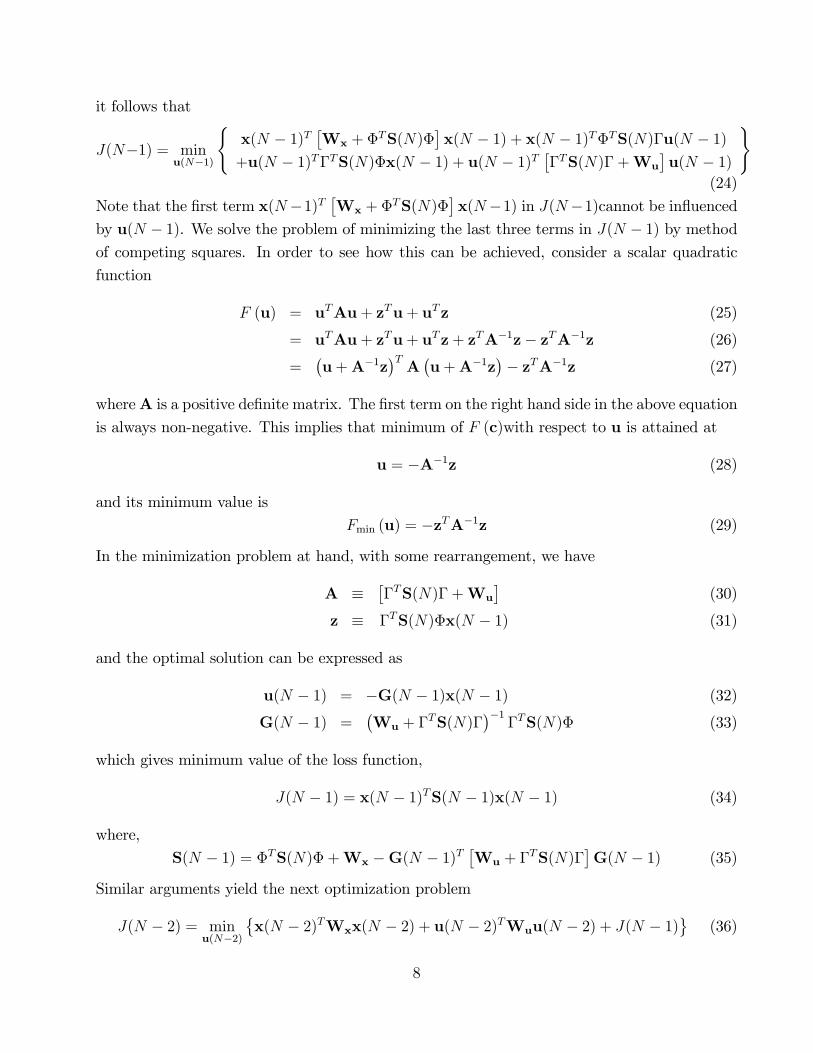
3.4.2 Separation Principle and Nominal Closed Loop Stability
To assess the nominal stability of the closed loop generated by observer - regulator pair, the
observer and the plant dynamics has be considered together. For example, the closed loop
system with Kalman predictor can be described by following set of equations
x(k + 1) = �x(k) + �u(k) +w(k) (59)
y(k) = Cx(k) + v(k) (60)
bx(k + 1jk) = �bx(kjk � 1) + �u(k) + L [y(k)�Cbx(kjk � 1)] (61)
Let us de�ne state estimation error
"(kjk � 1) = x(k)� bx(kjk � 1) (62)
It is easy to show that the dynamics of the estimation error is governed by
"(k + 1jk) = [�� LC]"(kjk � 1) +w(k)�Lv(k)
Combining the error dynamics with system dynamics and rearranging, we arrive at the following
equation governing the closed loop dynamics"x(k + 1)
"(k + 1jk)
#=
"[�� �G1] �G1
[0] [�� LC]
#"x(k)
"(kjk � 1)
#
+
"I
I
#w(k) +
"[0]
�L
#v(k) (63)
Thus, the unforced dynamics of LQG controller is determined by dynamics of LQ controller is
governed by eigenvalues of matrix
�c =
"[�� �G1] �G1
[0] [�� LC]
#(64)
Since
det [�I��c] = det [�I� (�� �G1)] det [�I� (�� LC)] (65)
it implies that the eigen values of matrices [�� �G1] and [�� LC] determine the stabilitycharacteristics of the nominal closed loop system. Thus, designing state feedback controller
and state observer to be individually stable ensures stability of the closed loop (separation
principle). As a consequence, if the system under consideration is observable and controllable,
then the resulting closed loop is guaranteed to be stable if weighting matrices in LQ formulation
13

are chosen to be positive de�nite / semi-de�nite and the Kalman predictor (or �lter) is used
for state estimation.
It may be noted that the separation principle does not restrict the type of observer used for
state estimation or the method used for designing the state feedback control law. For example,
the observer can be a Luenberger observer designed using the pole placement approach such
that
�[�� LC] < 1
Also, the feedback gain matrix G can be obtained using pole placement approach such that
�[�� �G] < 1
The nominal closed loop stability follows from the equation
det [�I��c] = det [�I� (�� �G)] det [�I� (�� LC)] (66)
which implies that designing a stable state feedback controller and a stable state observer
ensures stability of the closed loop. When the system under consideration is open loop stable,
one can also use the open loop observer
bx(k + 1jk) = �bx(kjk � 1) + �uu(k) (67)
and implement the state feedback control law while ensuring the nominal closed loop stability.
The main advantage of using LQ approach for designing the control law and Kalman predictor /
�lter for state estimation is that nominal stability and performance are ensured simultaneously.
3.5 Tracking and Regulation using Quadratic Optimal Controller
Linear quadratic regulator designed above can generate an o¤set if (a) the unmeasured distur-
bances are non-stationary, i.e. they have slowly drifting behavior (b) mismatch exists between
the plant and the model. Thus, it becomes necessary to introduce integral action in the control
to deal with plant-model mismatch and reject the drifting unmeasured disturbances. Also, the
regulator designed above only solves the restricted problem of moving the system from any
initial state to the origin. If it is desired to move the system from any initial condition to an
arbitrary setpoint, the state feedback control laws has to be modi�ed. The problem of regu-
lation in the face of unknown disturbances / plant-model mismatch and tracking an arbitrary
setpoint trajectory is solved by modifying the regulatory control law as follows
u(k)� us = �G1 [x(k)� xs] (68)
u(k) = us �G1 [x(k)� xs] (69)
14

where xs represent the steady state target corresponding to the setpoint, say r; and us represents
the steady state input necessary to reach this steady state target. This is equivalent to the
change of origin. In this section, we discuss various approaches to incorporate regulation in the
face of of drifting disturbances and tracking arbitrary setpoint changes.
3.5.1 Model Transformation for Output Regulation and Tracking
Before we move to handle unknown drifting disturbances and tracking arbitrary setpoint trajec-
tories, let us consider a simpli�ed scenario. Consider the problem of designing a LQ controller
for a system
x(k + 1) = �x(k) + �u(k) + ���s (70)
y(k) = Cx(k) +C��s (71)
where �srepresents input disturbance vector and �s represents additive output disturbance
vector. It is further assumed matrices (��;C�) and vectors (�s;�s) are known apriori. It is
desired to control this system at an arbitrarily speci�ed setpoint r�6= 0
�; i.e., y(k) = r as
k !1: The steady state behavior of this system is given by
xs = �xs + �us + ���s (72)
or
xs = [I��]�1 [�us + ���s] (73)
Since we require y(k) = r as k !1; it follows that at the steady state
r = Cxs +C��s (74)
r = C [I��]�1 [�us + ���s] +C��s (75)
= Kuus +K��s +C��s (76)
where
Ku = C [I��]�1 � and K� = C [I��]�1 ��
represent the steady state gain matrices. When the number of manipulated inputs equals the
number of controlled outputs and Ku is invertible, it follows that
us = K�1u [r�K��s �C��s] (77)
xs = [I��]�1�K�1u [r�K��s �C��s] +K��s
�(78)
15
Now, subtracting the steady state model equations (72-74) from the dynamic model equation
(70-71), we have
x(k + 1)� xs = � [x(k)� xs] + � [u(k)� us] (79)
[y(k)� r] = C [x(k)� xs] (80)
De�ning new perturbation variables �x(k) = [x(k)� xs] ;�u(k) = [u(k)� us] and �y(k) =[y(k)� r] ; we have a transformed system
�x(k + 1) = ��x(k) + ��u(k) (81)
�y(k) = C�x(k) (82)
We can now develop a LQ controller for the transformed system and arrive at a control law of
the form
�u(k) = �G1�x(k) (83)
which regulates the transformed system at the origin, �x = 0; which is equivalent to achieving
o¤set free behavior for the original system for the speci�ed stepoint and for the given disturbance
level. The LQ control law that solves servo and regulatory problem simultaneously can be
expressed as follows
u(k) = us �G1 [x(k)� xs] (84)
The situation where (�s;�s) are slowly time varying and / or the setpoint is r is time varying
van be handled by introducing time varying target steady states and time varying target steady
state inputs as follows
us(k) = K�1u [r(k)�K��s(k)�C��s(k)] (85)
xs(k) = [I��]�1�K�1u
hr(k)�K��s(k)�C��s(k)
i+K��s(k)
�(86)
and modifying the control law as follows
u(k) = us(k)�G1 [x(k)� xs(k)] (87)
Note that, the above modi�cation implicitly assumes that unmeasured disturbances remain
constant in future i.e.
�s(k + j + 1) = �s(k + j)
�s(k + j + 1) = �s(k + j)
for j = 0; 1; 2; ::::.1: This modi�cation facilitates regulation in the face of drifting measureddisturbances and time varying setpoints.
16

3.5.2 Dealing with Unmeasured Disturbances and Model Plant Mismatch
The formulation presented in the previous section caters to the case where the unmeasured dis-
turbances are measured. In practice, however, systems are invariably subjected to (additional)
drifting unmeasured disturbances and model plant mismatch. Let us assume that a Kalman
predictor is developed using the nominal set of model parameters as follows
e(k) = y(k)�Cbx(kjk � 1) (88)bx(k + 1jk) = �bx(kjk � 1) + �u(k) + Le(k) (89)
In the absence of model plant mismatch or drifting unmeasured disturbances, it can be shown
that the innovation signal e(k) is a zero mean Gaussian process. The innovation sequence,
however, is no longer a zero mean Gaussian process in the presence of following scenarios,
which are referred to as Model Plant Mismatch (MPM) in the rest of the text.
� Plant-model parameter mismatch: Plant dynamics evolves according to
ex(k + 1) = �ex(k) + �u(k) +w(k) (90)
y(k) = Cex(k) + v(k) (91)
where (�;�;C) are di¤erent from (�;�;C) used in the model
� Plant-model structural mismatch: Models for controller synthesis are often low orderapproximations of the plant dynamics in the desired operating range. This results in a
structural mismatch between the plant model. Thus, the system under consideration
could be evolving as
�(k + 1) = e��(k) + e�u(k) + ew(k) (92)
y(k) = eC�(k) + v(k) (93)
while the controller synthesis is based on (1-2). Here, dimensions of the plant state vector
(�) are di¤erent from the dimensions of the model state vector (x). As a consequence,
not just the entrees but the dimensions or (e�; e�; eC) are di¤erent from (�;�;C):
� Unmeasured drifting (colored) disturbances: Plant dynamics is a¤ected by someunknown drifting colored disturbance d(k)
ex(k + 1) = �ex(k) + �u(k) + �dd(k) +w(k) (94)
y(k) = Cex(k) + v(k) (95)
which is an autocorrelated (colored) stochastic process and which has not been accounted
for in the model.
17

� Nonlinear plant dynamics: Dynamics of most real systems are typically nonlinear andthis leads to errors due to approximation of dynamics using a local linear model
It is possible to modify the formulation presented in the previous section to deal with these
scenarios. There are two approaches to estimate the moving steady state targets and implement
the control law using a state observer:
� Innovation bias approach: Filtered innovation signal e(k) = y(k)� by(kjk � 1) is used asa proxy for the unmeasured disturbances
� State augmentation approach : By this approach disturbance vectors (�s(k);�s(k)) areestimated together with the states
We describe these approaches in detail.
Innovation Bias Approach In the presence of MPM, the sequence fe(k)g becomes coloredand has signi�cant power at the control relevant low frequency region. The low frequency
drifting mean of fe(k)g can be estimated using a simple unity gain �rst order �lter of the form
ef (k) = �e ef (k � 1) + [I��e]e(k) (96)
�e = diagh�1 �2 ::: �r
i0 � �i < 1 for i = 1; 2; :::; r are tuning parameters
where 0 � �i < 1 are tuning parameters. This �ltered signal can be taken as a proxy for thelow frequency unmeasured disturbances / model plant mismatch. Thus, we assume
� unmeasured disturbance in the state dynamics, �s(k) � ef (k) and �� � L
� unmeasured disturbance in the outputs, �s(k) � ef (k) and C� � Ir
and use control law (87) together with equations (86) and (85). It is also assumed that
these disturbances remain constant over the future, i.e. these disturbances behave according
the following linear di¤erence equations
�(k + j + 1) = �(k + j) for j = 1; 2; 3; :::: (97)
�(k) = ef (k) (98)
and
�(k + j + 1) = �(k + j) for j = 1; 2; 3; :::: (99)
�(k) = ef (k) (100)
18
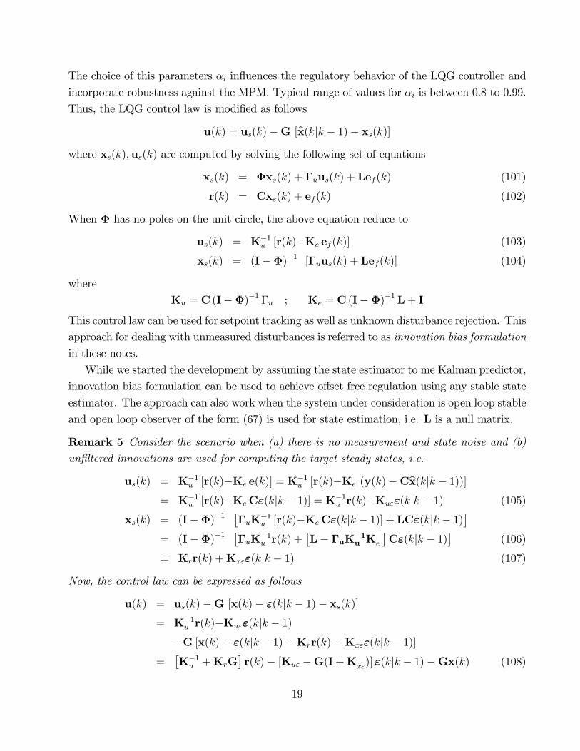
The choice of this parameters �i in�uences the regulatory behavior of the LQG controller and
incorporate robustness against the MPM. Typical range of values for �i is between 0.8 to 0.99.
Thus, the LQG control law is modi�ed as follows
u(k) = us(k)�G [bx(kjk � 1)� xs(k)]where xs(k);us(k) are computed by solving the following set of equations
xs(k) = �xs(k) + �uus(k) + Lef (k) (101)
r(k) = Cxs(k) + ef (k) (102)
When � has no poles on the unit circle, the above equation reduce to
us(k) = K�1u [r(k)�Ke ef (k)] (103)
xs(k) = (I��)�1 [�uus(k) + Lef (k)] (104)
where
Ku = C (I��)�1 �u ; Ke = C (I��)�1 L+ I
This control law can be used for setpoint tracking as well as unknown disturbance rejection. This
approach for dealing with unmeasured disturbances is referred to as innovation bias formulation
in these notes.
While we started the development by assuming the state estimator to me Kalman predictor,
innovation bias formulation can be used to achieve o¤set free regulation using any stable state
estimator. The approach can also work when the system under consideration is open loop stable
and open loop observer of the form (67) is used for state estimation, i.e. L is a null matrix.
Remark 5 Consider the scenario when (a) there is no measurement and state noise and (b)un�ltered innovations are used for computing the target steady states, i.e.
us(k) = K�1u [r(k)�Ke e(k)] = K
�1u [r(k)�Ke (y(k)�Cbx(kjk � 1))]
= K�1u [r(k)�KeC"(kjk � 1)] = K�1
u r(k)�Ku""(kjk � 1) (105)
xs(k) = (I��)�1��uK
�1u [r(k)�KeC"(kjk � 1)] + LC"(kjk � 1)
�= (I��)�1
��uK
�1u r(k) +
�L� �uK�1
u Ke
�C"(kjk � 1)
�(106)
= Krr(k) +Kx""(kjk � 1) (107)
Now, the control law can be expressed as follows
u(k) = us(k)�G [x(k)� "(kjk � 1)� xs(k)]= K�1
u r(k)�Ku""(kjk � 1)�G [x(k)� "(kjk � 1)�Krr(k)�Kx""(kjk � 1)]
=�K�1u +KrG
�r(k)� [Ku" �G(I+Kx")] "(kjk � 1)�Gx(k) (108)
19

State Augmentation Approach By this approach, the state space model (1-2) is aug-
mented with extra arti�cial states as follows
x(k + 1) = �x(k) + �uu(k) + �� �(k) +w(k) (109)
�(k + 1) = �(k) +w�(k) (110)
�(k + 1) = �(k) +w�(k) (111)
y(k) = Cx(k) +C��(k) + v(k) (112)
where � 2 Rs and � 2 Rt are input and output disturbance vectors while vectorsw� 2Rsand w� 2 Rt are zero mean white noise sequences with covariances Q� and Q�; respectively.
The model coe¢ cient matrices (��, C�) and noise covariances matrices (Q�, Q�) are treated
as tuning parameters, which can be chosen to achieve the desired closed loop disturbance
rejection characteristics. Note that the total number of extra states cannot exceed the number
of measurements due to the requirement that the additional states should be observable. Typical
choices of the arti�cial state variables and the corresponding coupling matrices are as follows
� Output bias formulation: A simple approach is to view the drifting disturbances ascausing a bias in the measured outputs, i.e., we can choose
�� = [0] ;Q� = [0] ; C� = I ; Q� = �2I
� Input Bias Formulation: The elements of vector � can be viewed as bias in r manip-
ulated inputs. When the number of manipulated inputs equals the number of measured
outputs (r = m), then we can choose
�� = �u ;Q� = �2I ; C� = [0] ; Q� = [0]
If number of manipulated inputs exceeds the number of measurements, then r linearly
independent columns of �u can be selected as ��:
� Disturbance bias formulation: When the state space model is derived from �rst
principles, it is possible to choose
�� = �d ;Q� = �2I
provided number of disturbance variables (d) = r: If d > r; then r linearly independent
columns of �d can be chosen as ��:
In all the above cases, �2 is treated as a tuning parameter. The above set of equations can
be combined into an augmented state space model of the form
xa(k + 1) = �axa(k) + �uau(k) +wa(k) (113)
y(k) = Caxa(k) + v(k) (114)
20

where
xa(k) =
264 x(k)�(k)
�k)
375 ; wa(k) =
264 w(k)w�(k)
w�k)
375�a =
264 � �� [0]
[0] I� [0]
[0] [0] I�
375 ; �ua =
"�u
0
#
Ca =hC [0] C�
i
R1a = E�wa(k)wa(k)
T�=
264 R1 [0] [0]
[0] Q� [0]
[0] [0] Q�
375R12a = E
�wa(k)v(k)
T�=
"R12
[0]
#R2a = E
�v(k)v(k)T
�= R2
This augmented model can be used for developing a Kalman predictor of the form
ea(k) = y(k)�Cbxa(kjk � 1) (115)bxa(k + 1jk) = �abxa(kjk � 1) + �uau(k � 1) + Laea(k) (116)
where the steady state Kalman gain is obtained by solving the corresponding steady state
Riccati equations
La =��aPa1C
Ta +R12a
� �CaPa1C
Ta +R2
��1(117)
Pa1 = �aPa1�Ta +R1 � La
�CaPa1C
Ta +R2
�LTa (118)
In order to maintain the observability of the arti�cially introduced states, the number of ad-
ditional states introduced in the augmented model should not exceed the number of measured
outputs . When the state space model (10-11) is observable and stable with no integrating
modes, the augmented state space model will be observable (detectable) in most of the cases.
The control law (87) is now implemented using the estimates of �(k) and �(k): Thus,
when number of inputs (m) equals the number of controlled outputs (r), the target states are
estimated as follows
us(k) = K�1u
hr(k)�K�
b�(kjk � 1)�C�b�(kjk � 1)i (119)
xs(k) = (I��)�1h�uK
�1u [r(k)�C�b�(kjk � 1)] + ��� � �uK�1
u K�
� b�(kjk � 1)i (120)For the case m = r; two special cases of quadratic optimal tracking control law are
21

� Output bias formulation: In this case we have �� = [0] ; C� = I; which implies thatK� = [0] and computation for xs(k);us(k) reduces to
us(k) = K�1u [r(k)� b�(kjk � 1)] (121)
xs(k) = (I��)�1 �uK�1u [r(k) � b�(kjk � 1)] (122)
� Input Bias Formulation: In this case we have �� = �u ; C� = [0];which implies that
K� = Ku and computation for xs(k);us(k) reduces to
us(k) = K�1u r(k)� b�(kjk � 1) (123)
xs(k) = (I��)�1 �uK�1u r(k) (124)
When number of the manipulated inputs (m) is not equal to number of controlled outputs
(r), matrix K�1u in the above expression should be replaced by Ky
u; i.e., pseudo-inverse of the
steady state gain matrix Ku:
4 Model Predictive Control
LQG formulation described above provides a systematic approach to designing a control law
for linear multi-variable systems. However, main di¢ culty associated with the classical LQG
formulation is inability to handle operating constraints explicitly. Operating constraints, such
as limits on manipulated inputs or on their rates of change, limits on controlled outputs aris-
ing out of product quality or safety considerations, are commonly encountered in any control
application. Model Predictive Control (MPC) refers to a class of control algorithms originally
developed in the process industry for dealing with operating constraints and multi-variable in-
teractions. MPC can be viewed as modi�ed versions of LQ (or LQG) formulation, which can
deal with the operating constraints in a systematic manner. This approach was �rst proposed
independently by two industrial groups
� Dynamic Matrix Control (DMC): Proposed by Cutler and Ramaker from Shell, USA in
1978.
� Model Algorithmic Control (MAC): proposed by Richalet (1978, France)
An MPC formulation is based on the following premise: given a reasonably accurate model
for system dynamics (and a su¢ ciently powerful computer), possible consequences of the current
and future manipulated input moves on the future plant behavior (such as possible constraint
22

violations in future etc.) can be forecasted on-line and used while deciding the input moves
in some optimal manner. To facilitate computational tractability, on-line forecasting is carried
out over a moving window of time. In this section, we develop a version of MPC formulation
based on the Kalman predictor.
4.1 Model Based Prediction of Future Behavior
At the centre of an MPC formulation is the state estimator, which is used to carry out on-line
forecasting. Let us assume that we have developed a Kalman predictor using model equations
(1-2) and used it to predict the current state
bx(kjk � 1)=�bx(k � 1jk � 2) + �u(k � 1) + Le(k � 1) (125)
and innovation
e(k) = y(k)�Cbx(kjk � 1)At each sampling instant, the Kalman predictor is used for predicting future behavior of the
plant over a �nite future time horizon of length p (called as the prediction horizon) starting
from the current time instant k: Let us assume that at any instant k; we are free to choose p
future manipulated input moves, which are denoted as follows
fu(kjk);u(k + 1jk)::::::u(k + p� 1jk)g
Since, in the absence of model plant mismatch (MPM), {e(k)}, is a whine noise sequence,
expected values of the future innovations is zero i.e. E [e(k + i)] = 0 for i = 1; 2; :::: . Thus, in
the absence of MPM (here abbreviation MPM includes the unmeasured drifting disturbances),
the observer can be used for forecasting over the future as follows
bx(k + 1jk) = �bx(kjk � 1) + �uu(kjk) + Le(k) (126)bx(k + j + 1jk) = �bx(k + jjk) + �uu(k + jjk) (127)
(for j = 1::::p� 1)
Such an ideal scenario, i.e. absence of MPM, rarely exists in practice and, as mentioned in the
previous section, the innovation sequence is a colored noise, which carries signatures of MPM
and drifting unmeasured disturbances. As a consequence, it becomes necessary to compensate
the future predictions for the MPM. Here, we describe two approaches to deal with this problem:
(a) innovation bias approach and (b) state augmentation approach.
23
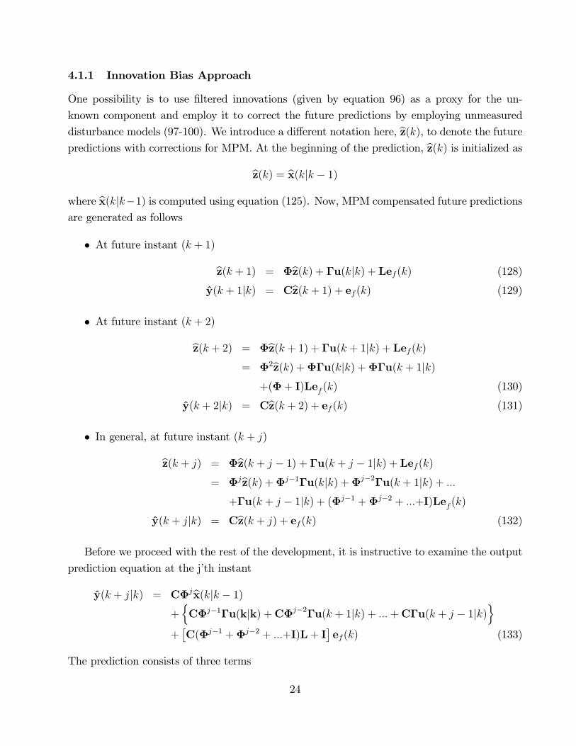
4.1.1 Innovation Bias Approach
One possibility is to use �ltered innovations (given by equation 96) as a proxy for the un-
known component and employ it to correct the future predictions by employing unmeasured
disturbance models (97-100). We introduce a di¤erent notation here, bz(k), to denote the futurepredictions with corrections for MPM. At the beginning of the prediction, bz(k) is initialized as
bz(k) = bx(kjk � 1)where bx(kjk�1) is computed using equation (125). Now, MPM compensated future predictions
are generated as follows
� At future instant (k + 1)
bz(k + 1) = �bz(k) + �u(kjk) + Lef (k) (128)
y(k + 1jk) = Cbz(k + 1) + ef (k) (129)
� At future instant (k + 2)
bz(k + 2) = �bz(k + 1) + �u(k + 1jk) + Lef (k)= �2bz(k) +��u(kjk) +��u(k + 1jk)
+(�+ I)Lef (k) (130)
y(k + 2jk) = Cbz(k + 2) + ef (k) (131)
� In general, at future instant (k + j)
bz(k + j) = �bz(k + j � 1) + �u(k + j � 1jk) + Lef (k)= �jbz(k) +�j�1�u(kjk) +�j�2�u(k + 1jk) + :::
+�u(k + j � 1jk) + (�j�1 +�j�2 + :::+I)Lef (k)
y(k + jjk) = Cbz(k + j) + ef (k) (132)
Before we proceed with the rest of the development, it is instructive to examine the output
prediction equation at the j�th instant
y(k + jjk) = C�jbx(kjk � 1)+nC�j�1�u(kjk) +C�j�2�u(k + 1jk) + :::+C�u(k + j � 1jk)
o+�C(�j�1 +�j�2 + :::+I)L+ I
�ef (k) (133)
The prediction consists of three terms
24

� TermC�jbx(kjk�1) signi�es e¤ect of the current state estimate over the future dynamics.� Term
�C�j�1�u(kjk) + ::::+C�u(k + j � 1jk)
quanti�es e¤ects of current and future
input moves over the predictions
� Term [(�j�1 + :::+I)L+ I] ef (k) attempts to quantify e¤ect or MPM over the predictions
It may be noted that, at a given instant k, the �rst and the third term are invariant. We
can only choose the current and future manipulated input moves, fu(kjk); :::;u(k + p� 1jk)g ;to in�uence the future dynamic behavior.
Remark 6 For an open loop stable system, predictions can be carried out using open loopobserver of the form bx(kjk � 1)=�bx(k � 1jk � 2) + �u(k � 1) (134)
The model predictions in such scenario are carried out as follows
bz(k + j) = �bz(k + j � 1) + �u(k + j � 1jk) (135)
y(k + jjk) = Cbz(k + j) + ef (k) (136)bz(k) = bx(kjk � 1) (137)
for j = 1; 2; :::p; where ef (k) represnts residuals
e(k) = y(k)�Cbx(kjk � 1)�ltered using equation (96). The resulting predictions are qualitatively similar to the DMC
formulation.
Remark 7 The initial MPC formulations, such as DMC or MAC, employed �nite impulse
response (FIR) or step response models for dynamic modeling and predictions. Many industrial
versions of MPC still use these model forms for modeling and predictions. The predictions
carried out using the state space model (125) are not di¤erent from the predictions carried out
using an FIR model. To see the connection, consider the state space model given by equation
(17)-(18) subjected to impulse input (with zero order hold) at k = 0; i.e.
u(0) =h1 1 :::: 1
iTu(k) = 0 for k > 0
with x(0) = 0 .The output of the system is given by
y(k) = H(k)u(0) where H(k) = C�k�1� for k > 0 (138)
25

where H(k) : k = 1; 2; :::: represent the impulse response coe¢ cients. Thus, assuming L = [0];
the output prediction equation (133) can be expressed as follows
y(k + jjk) = C�jbx(kjk � 1) + ef (k)+ fH(j)u(kjk) +H(j � 1)u(k + 1jk) + :::+H(1)u(k + j � 1jk)g (139)
which is similar to the prediction equation used in industrial MPC formulations.
4.1.2 State Augmentation Approach
Alternate approach to account for MPM is to augment the state space model with arti�cially
introduced input and / or output disturbance variables, which behave as integrated white noise
sequences, as given by equations (109-112). Typical choices of the arti�cial state variables and
the corresponding coupling matrices have been discussed in Section 2.3. This augmented model
can be used for developing a Kalman predictor of the form
bxa(kjk � 1) = �abxa(k � 1jk � 2) + �uau(k � 1) + Laea(k � 1) (140)
ea(k) = y(k)�Cbxa(kjk � 1) (141)
where La represents the steady state Kalman gain is obtained by solving the corresponding
steady state Riccati equations. Since the augmented observer accounts for MPM through
explicit estimation of drifting disturbance terms, it may be expected that the fea(k)g is zeromean white noise process. The optimal predictions of the states based on the augmented state
space model can be generated as follows
bxa(k + 1jk) = �abxa(kjk � 1) + �uau(kjk) + Laea(k) (142)bxa(k + j + 1jk) = �abxa(k + jjk) + �uau(k + jjk) (143)
(for j = 0; 1::::p� 1) (144)by(k + jjk) = Cabxa(k + jjk) (for j = 1::::p) (145)
Remark 8 A common modi�cation to the above formulation is to restrict the future degrees offreedom to q future manipulated input moves
fu(kjk);u(k + 1jk)::::::u(k + q � 1jk)g
and impose constraints on the remaining of the future input moves as follows
u(k + qjk) = u(k + q + 1jk) = :::::: = u(k + p� 1jk) = u(k + q � 1jk) (146)
26

Here, q is called as the �control horizon�. Alternatively, q degrees of freedom over the future are
spread over the horizon using the concept of �input blocking�as follows
u(k + jjk) = u(kjk) :for j = m0 + 1; :::m1 � 1 (147)
u(k + jjk) = u(k +m1jk) :for j = m1 + 1;m2 � 1 (148)
::::::
u(k + jjk) = u(k +mijk) :for j = mi + 1;mi+1 � 1 (149)
:::::::::::
u(k + jjk) = u(k +mq�1jk) :for j = mq�1 + 1;mq � 1 (150)
where mj are selected such that
m0 = 0 < m1 < m2 < :::: < mq�1 < mq = p (151)
4.2 Conventional Formulation of MPC
The model used for developing an industrial MPC scheme is often developed from the operating
data and the state vector may not have any physical meaning. In such cases, MPC is formulated
as an output control scheme as follows. During this development, we assume that only q future
manipulated input moves (i.e. equal to the control horizon) are to be decided.
Let us assume that fyr(k + jjk) : j = 1; 2; ::::pg denotes future desired setpoint trajectory atinstant k:Given the setpoint trajectory, the model predictive control problem at the sampling
instant k is de�ned as a constrained optimization problem whereby the future manipulated
input moves u(kjk);u(k + 1jk)......u(k + q � 1jk) are determined by minimizing an objectivefunction J de�ned as follows
J = E(k + pjk)Tw1E(k + pjk) +pXj=1
E(k + jjk)TweE(k + jjk)
+
q�1Xj=0
�u(k + jjk)Tw�u�u(k + jjk) (152)
where
E(k + jjk) = yr(k + jjk)� by(k + jjk) for j = 1; 2; ::::p (153)
represents predicted control error and
�u(k + jjk) = u(k + jjk)� u(k + j � 1jk) (154)
j = 1; :::q � 1�u(kjk) = u(kjk)� u(k � 1) (155)
27
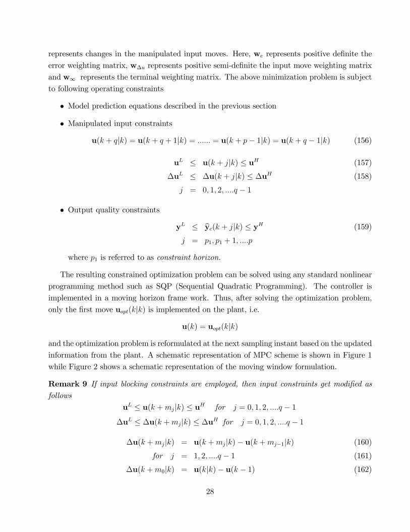
represents changes in the manipulated input moves. Here, we represents positive de�nite the
error weighting matrix, w�u represents positive semi-de�nite the input move weighting matrix
and w1 represents the terminal weighting matrix. The above minimization problem is subject
to following operating constraints
� Model prediction equations described in the previous section
� Manipulated input constraints
u(k + qjk) = u(k + q + 1jk) = :::::: = u(k + p� 1jk) = u(k + q � 1jk) (156)
uL � u(k + jjk) � uH (157)
�uL � �u(k + jjk) � �uH (158)
j = 0; 1; 2; ::::q � 1
� Output quality constraints
yL � byc(k + jjk) � yH (159)
j = p1; p1 + 1; ::::p
where p1 is referred to as constraint horizon.
The resulting constrained optimization problem can be solved using any standard nonlinear
programming method such as SQP (Sequential Quadratic Programming). The controller is
implemented in a moving horizon frame work. Thus, after solving the optimization problem,
only the �rst move uopt(kjk) is implemented on the plant, i.e.
u(k) = uopt(kjk)
and the optimization problem is reformulated at the next sampling instant based on the updated
information from the plant. A schematic representation of MPC scheme is shown in Figure 1
while Figure 2 shows a schematic representation of the moving window formulation.
Remark 9 If input blocking constraints are employed, then input constraints get modi�ed asfollows
uL � u(k +mjjk) � uH for j = 0; 1; 2; ::::q � 1
�uL � �u(k +mjjk) � �uH for j = 0; 1; 2; ::::q � 1
�u(k +mjjk) = u(k +mjjk)� u(k +mj�1jk) (160)
for j = 1; 2; ::::q � 1 (161)
�u(k +m0jk) = u(kjk)� u(k � 1) (162)
28

Figure 1: Schematic Representation of MPC Scheme
Remark 10 When the number of controlled outputs exceeds the number of manipulated inputs,then it is possible to specify setpoints only for the number of outputs equal to or less than the
number of manipulated inputs. For the remaining controlled outputs, it is possible to de�ne
only ranges or zones in which they should lie by imposing bounds on the predicted outputs. Such
outputs are often referred to as zone control variables in the MPC parlance.
Remark 11 When the number of manipulated inputs (m) exceeds the number of controlledoutput (r), then it is possible to specify (m � r) inputs through optimization and leave only mdegrees of freedom to MPC. Many commercial MPC implementations solve a separate linear
programming (LP) problem, which employes linear steady state model with a suitable economic
objective function, online to independently decide these (m� r) inputs.
4.2.1 Tuning Parameters
The predictive control formulation has many parameters that need to be judiciously chosen by
the control system designer.
� Prediction Horizon (p) and Control Horizon (q) : The closed loop stability and thedesired closed loop performance can be achieved by judiciously selecting the prediction
horizon p; control horizon q. Typically, prediction horizon is selected close to the open
loop settling time while control horizon (q) is chosen signi�cantly smaller (say between
1 to 5). Since the moving horizon formulation implies that a constrained optimization
problem has to be solved on-line at each sampling instant, time required for solving the
29

Figure 2: Schematic Representation of Moving Window Formulation (Kothare et al., 2000)
optimization problem is a major concern while developing an MPC scheme. The choice
of relatively smaller control horizon reduces the dimension of the optimization problem
at each sampling instant and thereby reduces the time for on-line computations.
� Weighting matrices: The weighting matrices we and w�u are typically chosen to be
diagonal and can be e¤ectively used to specify relative importance of elements of control
error vectors and elements of manipulated input vectors, respectively.
� Future Setpoint Trajectory: In addition to predicting the future output trajectory,at each instant, a �ltered future setpoint trajectory is generated using a reference system
of the form
xr(k + j + 1jk) = �rxr(k + jjk) + [I��r] [r(k)� y(k)] (163)
yr(k + j + 1jk) = y(k) + xr(k + j + 1jk) (164)
for j = 0; 1; ::::p� 1
�r = diagh 1 2 ::: r
i0 � i < 1 for i = 1; 2; :::; r are tuning parameters
with initial condition xr(kjk) = 0: Here, r(k) 2 Rr represents the setpoint vector. Thecoe¢ cient matrices of the reference system are tuning parameters which can be selected
30

to achieve the desired closed loop tracking performance. Typical range of values for i is
between 0.8 to 0.99. In order to ensure the free servo responses for step changes in the
setpoint, the coe¢ cient matrices of the reference system should be selected such that the
steady state gain of the reference system is equal to the identity matrix, i.e.
Crf (I��r)�1�r = I
Typically, the reference system is selected such that its transfer function matrix is diagonal
with unit gain �rst (or higher) order low pass �lters on the main diagonal.
� Robustness against MPM: If the innovation bias formulation is employed for gener-ating the output predictions, then the diagonal elements of matrix �e in equation (96)
can be chosen to incorporate robustness against MPM. Typical range of values for �i is
between 0.8 to 0.99. In the state augmentation based formulation approach, the choice
of covariance matrices Q� and Q� decides the quality of the estimates of the arti�cially
introduced disturbance variables and thereby in�uences the quality of the regulatory re-
sponses.
4.2.2 Unconstrained MPC
To see connection between the conventional MPC formulation and state feedback controller,
we derive unconstrained MPC control law using innovation bias formulation. To begin with,
we assume that the control horizon (q) is equal to the prediction horizon (p) and later show
how to modify the formulation for (q < p) and input blocking. De�ning the future input vector
Up(k) and the predicted output vector bY(k) over the future horizon asUp(k) =
hu(kjk)T u(k + 1jk)T ::::::: u(k + p� 1jk)T
iT(165)
Us(k) =hus(k)
T us(k)T ::::::: us(k)
TiT
(166)
bY(k) =h by(k + 1jk)T by(k + 2jk)T ::::: by(k + pjk)T iT (167)
the prediction model
y(k + jjk) = C�jbx(kjk � 1)+nC�j�1�u(kjk) +C�j�2�u(k + 1jk) + :::+C�u(k + j � 1jk)
o+�C(�j�1 +�j�2 + :::+I)L+ I
�ef (k) (168)
for j = 1; 2; :::p can be expressed as a single vector equation
bY(k) = Sxbx(kjk � 1) + SuUp(k) + Seef (k) (169)
31

where
Sx =
26664C�
C�2
::::::
C�p
37775 ; Se =
26664CL+ Ir
C(�+ In)L+ Ir::::::
C(�p�1 +�p�2 + :::+In)L+ Ir
37775 (170)
Su =
26664C�u [0] [0] :::: [0]
C��u C�u [0] :::: [0]
::::: ::::: :::: ::: [0]
C�p�1�u C�p�2�u :::: ::: C�u
37775
=
26664H(1) [0] [0] :::: [0]
H(2) H(1) [0] :::: [0]
::::: ::::: :::: ::: [0]
H(p) H(p� 1) :::: ::: H(1)
37775 (171)
where H(j) represent the impulse response coe¢ cients as de�ned by equation (138). Here,
matrix Su is often referred to as dynamic matrix of the system.
If it is desired to implement input blocking constraints, then Su matrix needs to be modi�ed
as follows. Consider matrices {Imi: i = 1; 2; :::; q}, each of dimension (mi �mi�1 + 1)m �m
and de�ned as follows
Imi=
26664Im
Im
::::
Im
37775(mi�mi�1+1)m�m
Now, de�ne a matrix
pq = block diaghIm1 Im2 :::: Imq
i(pm�pm)
Now, let us de�ne a vector for future q manipulated input moves
Uq(k) =hu(kjk)T u(k +m1jk)T ::::::: u(k +mq�1jk)T
iT(172)
Then, it is easy to construct vector Up(k) de�ned by equation (165) starting from Uq(k) as
follows
Up(k) = pqUq(k)
Up(k) =hu(kjk)T ::: u(kjk)T ::: u(k +mq�1jk)T ::: u(k +mq�1jk)T
iT(173)
32

The vector form of prediction equation (165) is now modi�ed as follows
bY(k) = Sxbx(kjk � 1) + SuUq(k) + Seef (k) (174)
where
Su =
26664C�u [0] [0] :::: [0]
C��u C�u [0] :::: [0]
::::: ::::: :::: ::: [0]
C�p�1�u C�p�2�u :::: ::: C�u
37775pq (175)
De�ning the future reference trajectory vector R(k) as
R(k) =hyr(k + 1jk)T yr(k + 2jk)T ::::: yr(k + pjk)T
iT(176)
the predicted control error vector E(k) at instant k can be de�ned as follows
E(k) = R(k)� bY(k) (177)
The unconstrained version of the MPC control problem can be re-cast as follows
minUf (k)
(E(k)TWEE(k) + �Up(k)
TW�U �Up(k)
+ [Uq(k)�Us(k)]T WU [Uq(k)�Us(k)]
)(178)
whereWE andWU represents error weighting and input move weighting matrices, respectively,
and are de�ned as
WE = block diaghwe we :::: w1
i(pn�pn)
(179)
W�U = block diaghw�u w�u :::: w�u
i(qm�qm)
(180)
WU = block diaghwu wu :::: wu
i(qm�qm)
(181)
Here, �Up(k) is de�ned as
�Uq(k) =
26664u(kjk)� u(k � 1)u(k +m1jk)� u(kjk)::::::
u(k +mq�1jk)� u(k +mq�2jk)
37775 = Uq(k)�0u(k � 1) (182)
where
=
26664Im [0] [0] [0]
�Im Im [0] [0]
::: ::: ::: :::
[0] :::: �Im Im
37775(qm�qm)
; 0 =
26664Im
[0]
:::
[0]
37775(qm�m)
(183)
33

Here, Im represents m�m identity matrix. Now, let us examine the �rst term in the objective
function
E(k)TWEE(k) =hR(k)� bY(k)iTWE
hR(k)� bY(k)i
De�ning estimation error compensated setpoint trajectory
�(k) = [R(k)� Sxbx(kjk � 1)� Seef (k)]we have
R(k)� bY(k) = �(k)� SuUp(k)
E(k)TWEE(k) = �T (k)WE�(k) +UTq (k)S
TuWESuUq(k)� 2UT
q (k)STuWE�(k) (184)
Similarly, considering term
�Uq(k)TW�U �Uq(k) = [Up(k)�0u(k � 1)]TW�U [Up(k)�0u(k � 1)]
= UTq (k)
�TW�U
�Uq(k)� 2UT
q (k)�TW�U0
�u(k � 1)
+uT (k � 1)�T0W�U0
�u(k � 1) (185)
Similarly, we have
[Uq(k)�Us(k)]T WU [Uq(k)�Us(k)] = UT
q (k)WUUq(k)� 2UTq (k)WUUs(k)
+UTs (k)WUUs(k)
De�ning matrix
u =
26664Im
Im
:::
Im
37775(qm�m)
Us(k) = uus(k)
which consists of Im stacked q times, this term reduces to
[Uq(k)�Us(k)]T WU [Uq(k)�Us(k)] = UT
q (k)WUUq(k)� 2UTq (k)WUuus(k)
+uTs (k)TuWUuus(k) (186)
Using equations (184), (185) and (186), the unconstrained optimization problem (178) can be
reformulated as minimization of a quadratic objective function as follows
minUq(k)
1
2Uq(k)
THUq(k) +z(k)TUq(k) (187)
34

where
H = 2(STuWESu +TW�U+WU) (188)
z(k) = �2��STuWE
��(k) +
�TW�U0
�u(k � 1) +WUuus(k)
�(189)
This unconstrained problem can be solved analytically to compute a closed form control law.
The least square solution to above minimization problem is
[Uq(k)]opt = �H�1z(k) (190)
Since only the �rst input move is implemented on the process
uopt(kjk) = T0 [Uq(k)]opt = �
T0H
�1z(k) (191)
With some algebraic manipulations, control law (191) can be rearranged as follows
uopt(kjk) = �Gxbx(kjk � 1) +Guu(k � 1) +Gusus(k) +Geef (k) +GrR(k) (192)
where (Gu;Gus;Gx;Ge;Gr) are matrices of appropriate dimension derived by combining equa-
tions (188-189) with equation (191). From equation (191), it is easy to see that the uncon-
strained MPC control law can be viewed as a type of state feedback controller.
4.2.3 QP Formulation of MPC
The conventional MPC formulation with constraints on manipulated inputs and predicted out-
puts can now be re-cast as follows:
minUq(k)
(E(k)TWEE(k) + �Uq(k)
TW�U �Uq(k)
+ [Uq(k)�Us(k)]T WU [Uq(k)�Us(k)]
)(193)
subject to the following constraints
bY(k) = Sxbx(kjk � 1) + SuUp(k) + Seef (k) (194)
YL � bY(k) � YH (195)
uuL � Uq(k) � uuH (196)
u�uL � �Uq(k) � u�uH (197)
Note that above formulation has a quadratic objective function and linear constraints. Thus,
for improving the computational e¢ ciency, the above problem can be transformed into an
equivalent quadratic programming (QP) formulation as follows
35

minUq(k)
1
2Uq(k)
THUq(k) + +z(k)TUq(k) (198)
Subject to AUp(k) � B (199)
where
Ap =
2666666664
Iqm
�Iqm
�Su
�Su
3777777775; Bp =
2666666664
uuH
�uuL
u�uH +0uk�1
�u�uL �0uk�1
YH � Sxbx(kjk � 1)� Seef (k)Sxbx(kjk � 1) + Seef (k)�YL
3777777775Here, Ipm represents identity matrix of dimension p�m:The QP formulation is more suitable for on-line implementation as e¢ cient algorithms exist
for solving QP in polynomial time.
4.3 State Space Formulation of MPC
In this section, we present a state space formulation of MPC controller. For the sake of brevity,
a formulation is based on the input bias approach for future trajectory predictions is developed.
It is possible to develop a similar formulation based on state augmentation approach. This is
left as an exercise to the reader.
Thus, it is assumed that state predictions are generated as follows
bz(k + j) = �bz(k + j � 1) + �u(k + j � 1jk) + Lef (k) (200)bz(k) = bx(kjk � 1) (201)
for j = 1; 2; ::::p
where bx(kjk�1) represents estimate of the state generated using a suitable prediction estimator.4.3.1 Generation of Target States
First task is to generate target states, zs(k); and target inputs, us(k): It may be noted that
MPC formulation takes into account bounds on the manipulated inputs. Thus, unlike the LQG
case, target state computation is carried out by solving a constrained minimization problem.
If the number of controlled outputs exceeds or is equal to the number of manipulated inputs,
the target state can be computed by solving the following optimization problem
Min
us(k)[r(k)� ys(k)]we [r(k)� ys(k)]
36
Subject to
[I��)] zs(k) = �uus(k) + Lef (k) (202)
ys(k) = Czs(k) + ef (k) (203)
uL � us(k) � uH (204)
If the number of manipulated inputs is more than the number of controlled outputs, then
time-varying target state can be computed by solving the following optimization problem
min
us(k)us(k)
TwUus(k) (205)
subject to,
[I��)] zs(k) = �uus(k) + Lef (k) (206)
r(k) = Czs(k) + ef (k) (207)
uL � us(k) � uH (208)
4.4 State Space Formulation of MPC
Given the target states, the model predictive control problem at the sampling instant k is
de�ned as a constrained optimization problem whereby the future manipulated input moves
u(kjk);u(k + 1jk)......u(k + q � 1jk) are determined by minimizing an objective function Jde�ned as follows
J = [bz(k + p)� zs(k)]T w1 [bz(k + p)� zs(k)]+
pXj=1
[bz(k + j)� zs(k)]T wx [bz(k + j)� zs(k)] (209)
+
q�1Xj=0
[u(k + jjk)� us(k)]T wu [u(k + jjk)� us(k)] (210)
Here, wx represents positive de�nite state error weighting matrix and wu represents positive
de�nite the input weighting matrix. The terminal state weighting matrix w1 can be found by
solving discrete Lyapunov equation. When poles of � are inside the unit circle, the terminal
state weighting matrix w1 can be found by solving discrete Lyapunov equation given as
w1 = wx +�Tw1� (211)
When some poles of � are outside unit circle, the procedure for computing the terminal weight-
ing matrix is given in Muske and Rawlings (1993). The above minimization problem is subject
to following operating constraints
37

� Model prediction equations (200-201)
� Manipulated input constraints
u(k + qjk) = u(k + q + 1jk) = :::::: = u(k + p� 1jk) = u(k + q � 1jk) (212)
uL � u(k + jjk) � uH (213)
�uL � �u(k + jjk) � �uH (214)
j = 0; 1; 2; ::::q � 1
� If linearized version of a mechanistic model is used for developing the MPC scheme, thenit is possible to impose constraints on the predicted states as well
xL � bz(k + j) � xH (215)
j = p1; p1 + 1; ::::p
where p1 denotes the constraint horizon.
4.5 Nominal Stability (Goodwin et al., 2009)
Similar to LQ formulation, MPC formulation is based on minimization of a performance mea-
sure. The question that naturally arises is whether the resulting formulation guarantee stable
closed loop behavior. It is relatively easy to answer this question under the nominal conditions
i.e. in absence of MPM and under the deterministic settings. In this sub-section, we examine
nominal stability of a deterministic version of MPC under the following simplifying assumptions
� There is no model plant mismatch or unmeasured disturbances are absent and bothinternal model (i.e. observer) and plant evolve according to
x(k + 1) = �x(k) + �u(k) (216)
� The true states are perfectly measurable
� It is desired to control the system at the origin.
With the above assumptions, the MPC formulation developed in the previous section can
be posed as minimization of a loss function of the form
J(x(k);Up(k)) = x(k + p)Tw1x(k + j) +
pXj=1
x(k + j)Twxx(k + j)
+
p�1Xj=0
u(k + jjk)Twuu(k + jjk) (217)
38

with respect to Up(k): Though we have formulated MPC as minimization of a quadratic loss
function for the sake of keeping the development simple and facilitate connection with LQOC,
the MPC objective function can be formulated using any other suitable positive function of the
vectors involved. Thus, let us formulate MPC in terms of a generalized loss function
J�x(k);Up(k)
�= ' [x(k + p)] +
pXj=1
� [x(k + j);u(k + jjk)] (218)
where ' [x(k + p)] and � [x(k + j);u(k + jjk)] are positive functions of their respective argu-ments such that J
�x(k);Up(k)
�! 1 as kx(k)k ! 1. Thus, J
�x(k);Up(k)
�is a candidate
Lyapunov function. It is desired to minimize J�x(k);Up(k)
�subject to
Up(k) 2 �U
where �U is a closed and bounded set. Let us assume that an additional constraint of the form
x(k + p) = 0
is placed on the moving horizon optimization problem each time. Let us denote the optimal
solution of the resulting constrained optimization problem at instant k as
U�p(k) =
hu�(kjk)T u�(k + 1jk)T ::::::: u�(k + p� 1jk)T
iT(219)
In MPC formulation, we set u(k) = u�(kjk) and the optimization problem is solved again
over window [k + 1; k + p + 1]. It may be noted that u�(kjk) is some function of x(k), sayu�(kjk) = h [x(k)]. Let
x(k + 1) = �x(k) + �u�(kjk) = �x(k) + �h [x(k)] (220)
and x(k + p) = 0 be terminal state resulting from application of U�p(k) on the system (216).
Now, let
U�p(k + 1) =
hu�(k + 1jk + 1)T :::: u�(k + p� 1jk + 1)T u�(k + pjk + 1)T
iT(221)
represent the optimum solution of the MPC problem over the window [k+1; k+ p+1] and we
want to examine
�J�x;Uf
�= J
�x(k + 1);U�
p(k + 1)�� J
�x(k);U�
p(k)�
(222)
A non-optimal but feasible solution for the optimization problem over window [k+1; k+ p+1]
is
Up(k + 1) =hu�(k + 1jk)T u�(k + 2jk)T :::: u�(k + p� 1jk)T 0
iT(223)
39
for this feasible solution, the following inequality holds
J�x(k + 1);U�
p(k + 1)�� J
�x(k + 1);Up(k + 1)
�Thus, it follows that
J�x(k + 1);U�
p(k + 1)�� J
�x(k);U�
p(k)�� J
�x(k + 1);Up(k + 1)
�� J
�x(k);U�
p(k)�(224)
Now, since x(k+p) = 0 (by assumption), with application of the last element of Up(k+1) (i.e.
0) on (216) yields
x(k + p+ 1) = 0
and consequently
��x(k + p+ 1);0
�= 0
This, together with the fact that U�p(k) and Up(k + 1) share (p-1) sub-vectors, it follows that
J�x(k + 1);Uf (k + 1)
�� J
�x(k);U�
f (k)�
=
pXj=2
� [x(k + j);u�(k + jjk)]�pXj=1
� [x(k + j);u�(k + jjk)]
= �� [x(k); h [x(k)]] < 0 if x(k) 6= 0 (225)
Thus, it follows that
�J�x;Up
�= J
�x(k + 1);U�
p(k + 1)�� J
�x(k);U�
p(k)�� �� [x(k); h [x(k)]] < 0 if x(k) 6= 0
and the nominal closed loop system is globally asymptotically stable.
It is remarkable that we are able to construct a Lyapunov function using the MPC loss
function. Thus, under the nominal conditions, MPC controller guarantees global asymptotic
stability and optimal performance.
5 Summary
These lecture notes introduce various facets of model predictive control, which is formulation
derived from a discrete linear state space model. To begin with, linear quadratic optimal
regulator is developed and the resulting control law is implemented using states estimated from
a state estimator. Stability of the closed loop system, consisting of the observer and the plant,
is established under the nominal conditions by establishing the separation principle. The LQ
formulation is further modi�ed by introducing time varying target states and target inputs to
deal with the model plant mismatch and drifting unmeasured disturbances and to track changing
40
setpoints. We later move to develop the conventional MPC formulation, which is aimed at
dealing with the operating constraints. Unconstrained MPC formulation is shown to be a form
of state feedback controller. Constrained MPC is later formulated as a quadratic programming
problem to enhance e¢ ciency of the on-line computations. We then develop a state space model
based formulation of MPC, which is similar to the LQ formulation with constraints. The closed
loop stability is established under the nominal conditions for the deterministic linear model
based MPC formulation.
These notes only touch upon tip of the iceberg called MPC and are only meant to be an
introduction to a novice. A lot remains to be discussed. For example, important issue of robust
stability and robust design under MPM is not touched. Extensions, such as explicit MPC or
adaptive MPC, are not discussed. MPC formulations based on nonlinear dynamic models is
another well developed area. Meadows and Rawlings (1997) provide a tutorial introduction
to nonlinear model based predictive control. Henson (1998) and Qin and Badgwell (2003)
have reviewed nonlinear model based MPC formulations. Interested reader is referred to the
literature cited if he / she wants to know more about this exciting area. Hope this gentle
introduction is su¢ cient to tread that path.
6 References
Astrom, K. J. and B. Wittenmark, Computer Controlled Systems, Prentice Hall, 1990.
Camacho, E. C. and C. Bourdons, 1999, �Model Predictive Control�, Springer Verlag, London.
Franklin, G. F. and J. D. Powell, Digital Control of Dynamic Systems, Addison-Wesley, 1989.
Garcia, C. E., Prett, D. M. , Morari, M. Model predictive control: Theory and practice - A
survey. Automatica, 25 (1989), 335-348.
Glad, T., Ljung, L. Control Theory: Multivariable and Nonlinear Methods, Taylor and Francis,
2000.
Goodwin, G., Graebe, S. F., Salgado, M. E., Control System Design, Phi Learning, 2009.
Henson, M.A. (1998). Nonlinear Model Predictive Control : Current status and future direc-
tions. Computers and Chemical Engg,23 , 187- 202.
Lee, J.H. (1998). Modeling and Identi�cation for Nonlinear Model Predictive control:Requirements
present status and future needs. International Symposium on Nonlinear Model Predictive
control,Ascona, Switzerland.
41

Kothare, M. V., B. Mettler, M. Morari and P. Bendotti (2000) Level Control in the Steam
Generator of a Nuclear Power Plant, IEEE Transactions On Control Systems Technology,
Vol. 8, No. 1, 55-69.
Meadows, E.S. , Rawlings, J. B. (1997) Nonlinear Process Control, ( M.A. Henson and D.E.
Seborg (eds.), New Jersey: Prentice Hall, Chapter 5.
Morari, M. , Lee, J.H., (1999), Model Predictive Control: Past, Present and Future, Comp.
Chem. Engg., 23, 667-682.
Muske, K. R. , Rawlings, J. B., (1993). Model Predictive control with linear models, AIChE
J., 39, 262-287.
Muske, K. R. ;Badgwell, T. A. Disturbance modeling for o¤set-free linear model predictive
control. Journal of Process Control, 12 (2002), 617-632.
Patwardhan S.C. and S.L. Shah (2005) From data to diagnosis and control using generalized
orthonormal basis �lters. Part I: Development of state observers, Journal of Process
Control,15,7, 819-835.
Qin, S.J., Badgwell, T.A. A survey of industrial model predictive control technology, Control
Engineering Practice 11 (2003) 733-764.
Rawlings, J. B. and D. Q. Mayne, (2009), Model Predictive Control Theory and Design, North
Hill Publication.
Ricker, N. L., 1990, Model Predictive Control with State Estimation, Ind. Eng. Chem. Res.,
29, 374-382.
Sodderstrom, T. Discrete Time Stochstic Systems. Springer, 2003.
Yu, Z. H. , Li , W., Lee, J.H. , Morari, M. (1994), State Estimation Based Model Predictive
Control applied to Shell Control Problem: A Case Study, Chem. Eng. Sci., 14-22.
42