Embed Size (px)
Citation preview
A Generic Peer-to-Peer Network SimulatorNyik San Ting
Department of Computer ScienceUniversity of Saskatchewan
Saskatoon, Saskatchewan, S7N [email protected]
ABSTRACTPeer-to-Peer (P2P) systems are emerging as a “new” form ofdistributed computing with a strong emphasis on self-organization, decentralization and autonomy of theparticipating nodes. Self-organization, autonomy anddecentralization allow for highly adaptive, robust and scalablenetworks making P2P an increasingly interesting way todesign distributed systems. Unfortunately it is still verydifficult to develop P2P applications due to the complex andill understanding of interdependencies between the users,application, protocol and physical network. Furthermore, theP2P topology and the underlying network topology cangreatly influence the behavior of the P2P system.
This paper provides an overview of P2P protocols and a reviewof existing simulators. Based on the shortcomings of existingsimulators a novel layered simulator for P2P networks i sintroduced and evaluated.
KeywordsP2P Networks, Simulator
1. INTRODUCTIONIn the middle of the 90’s, the computational resources ofordinary desktop computers began to exceed the needs of theirusers, creating an ever-growing growing pool of unusedcomputational resources. An Intel study [7] estimates that inthe average organization the combined computationalresources of the desktop machines are 2.5 times larger thanthose of their centralized servers and high-end compute nodes.The now famous SETI@Home [23] project demonstrates thatby using simple P2P techniques it is possible to harvest thescattered resources of thousands of desktop computers in anefficient way enabling the analysis of large data at virtuallynow costs. The success of the SETI@Home project, whichforms one of the most powerful compute-networks today, hasresulted in an increasing interest in the study and deploymentof P2P networks.The field of P2P networks is still in its infancy with newapplications and protocols emerging on a nearly daily basis.However, due to the difficulties in evaluating them prior to
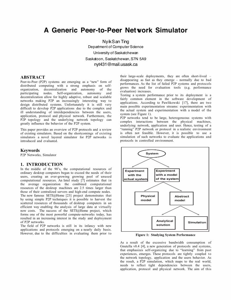
their large-scale deployments, they are often short-lived –disappearing as fast as they emerge – normally due to badperformances. As the list of failed P2P systems and protocolsgrows the need for evaluation tools (e.g. performanceevaluation) increases.Testing a system performance prior to its deployment is afairly common element in the software development ofapplications. According to Pawlikowski [17], there are twomain possible experimentation streams: experimentation withthe actual system and experimentation with a model of thesystem (see Figure 1).P2P networks tend to be large, heterogeneous systems withcomplex interactions between the physical machines,underlying network, application and user. Hence, testing of a“running” P2P network or protocol in a realistic environmentis often not feasible. However, it is possible to use asimulation of such networks to evaluate the applications andprotocols in controlled environment.
Figure 1: Studying System Performance
As a result of the excessive bandwidth consumption ofGnutella v0.4 [4], a new generation of protocols and systems,that emphasizes self-organizing due to “learning” from pastexperiences, emerges. These protocols are tightly coupled tothe network topology, application and the users behavior. Asthe result, a P2P simulation, which maps to the real world,needs to reflect tight dependencies between the users,application, protocol and physical network. The aim of this
paper is to motivate the need for generic P2P networksimulators. It is structured as follows: in section 2 the majorP2P protocols are presented. This is followed by an overviewand evaluation of the P2P simulators currently used. Based onthe shortcomings of existing simulators a new approach forsimulating P2P systems is presented in section 4. The paperconcludes with a summary and a presentation of future work.
2. Peer-to-Peer ProtocolsOver time, a variety of P2P protocols and systems haveemerged. This paper therefore focuses only on the mostprominent examples of certain types of P2P protocols.Resource allocation is one central element in every P2Pprotocol. Existing approaches can be grouped [13] into one ofthe following three basic categories:
2.1 Centralized directory model.This model is based on the availability of a server used as acentralized directory service, managing the information of allthe participating peers in the P2P network. In order to join andparticipate in the network, a peer must directly connect to thecentral server. While the peers mainly in full control of theirlocally owned resources, they need the server for advertisingtheir resources or locating needed resources of other peers.
This centralized approach solution provides good resourceallocation performance and network manageability. However,using a centralized component introduces a central point offailure.
2.1.1 Napster [14]Napster was a centralized P2P file-sharing network that wasforced to shut down as a result of copyright infringements. InNapster, a cluster of central servers maintained the informationof the content offered by the peers of the network. All the peersin the Napster network had to connect to the server, which alsohandled their resource request queries. Upon receiving theresults of the match from the central server, the peer,establishes a connection to the resource-providing peer andstarted to consume the resource e.g. downloads the filedirectly.
2.1.2 SETI@HomeSETI@Home was designed to aid the process of discoveringextraterrestrials by harvesting the unused processing power ofidle desktops via the Internet. A centralized server stores andpackages the signal data of radio telescopes into small chunksthat can be processed by an average desktop machine. Userswilling to participate in this “hunt for ET” have to downloadand install the signal processing data provided bySETI@Home. Depending on the OS, users download aSETI@Home screen-saver that is used as a means of detectingidle-cycles or software designed to run as a backgroundprocess. When the SETI@Home software recognizes that thehost has idle resources (based on the settings of the user), i tcontacts the central server of SETI@Home to download achunk of data (ca. 200 KB). Upon the successful download, thepeer starts a series of signal processing activities and sendsthe results (ca. 80 KB) back to the server requesting new dataand restarting the compute cycle.
Despite the impressive performance of the SETI@Homenetwork, it is important to point out that it can only handlesingle process multiple data (SPMD) compute problems due to
the inability of SETI@Home peers to communicate andtherefore coordinate their processing of data.
2.2 Flooded request modelThe flooded request model is a “pure” P2P model since it doesnot require any centralized infrastructure. Due to the absenceof any predefined structures, resource requests of a peer arehandled by use of message flooding.
Gnutella [4] is a good example for the flooded requestprotocols. Gnutella has been designed for information storageand searching in distributed system with decentralizedcontrol. Currently two main Gnutella protocols exist: 0.4 and0.6.
2.2.1.1 Overview of Gnutella v0.4A Gnutella 0.4 peer (X) connects to the network byestablishing a TCP/IP connection to a peer (Y) that is currentlyon the network. After connecting, X sends a request string(“GNUTELLA CONNECT/0.4\n\n”) to establish a link to peer Y.Peer Y can accept the connection, by sending “GNUTELLAOK\n\n”, or refuse the connection, by sending any responsesother than the accept connection string. Once the peer X i sconnected to the network, it can communicate with other peersby sending and receiving Gnutella messages (also calleddescriptors).
Every descriptor has 22 bytes of message headers consistingof: descriptor ID (byte 0 to 15), payload descriptor (byte 16),TTL (byte 17), Hops (byte 18), and payload_length (byte 19 to22). The descriptor ID is a unique identifier of the message inthe network and typically created by using a random generator.The Time-To-Live (TTL) is the number of times the messagewill be forwarded by Gnutella peers before being deleted. Hopsrepresent the number of times the message has been forwardedby peers. Each time a message is being forwarded, themessage’s TTL is being decremented by one and the hop i sincreased by one. The Payload descriptor contains the code forthe type of the message: 0x00 for Ping message, 0x01 for Pongmessage, 0x40 for Push message, 0x80 for Query message, and0x81 for a Query_Hit message. The payload_length containsthe length of the remainder message (payload) following afterthe header. Hence, a message’s total length is 22 bytes + thepayload_length; the next message is located exactlypayload_length after the current header.
A peer can discover the information (IP address and portnumber, number of resources, etc.) about other peers bysending a ping message. A ping message has payload_lengthof zero - no payload. Upon receiving a Ping message, a peer,will forward the ping messages to all the directly connectedpeers, except the peer who sent the ping message. At the sametime, the peer will send a pong message, which has the samedescriptor ID as the corresponding ping message, in responseto the peer who sent the ping message. A pong message has apayload that contains the number of files shared, the numberof kilobytes shared, IP address, and port number of theresponding peer.
While ping and pong messages are used for discovering otherpeers in the network, query and hit messages are used forlocating resources. To locate a resource, a peer sends a querymessage that has a payload containing the required minimumnetwork speed of a potential resource providing peers and asearch string for describing the requested resource. Similar tothe ping messages, a query received by a peer is broadcasted toall the directly connected peers (except the sender of the
GNUTELLA CONNECT/0.6<cr><lf>
User-Agemt:BearShare<cr><lf>
X-Ultrapeer:True<cr><lf>
Listen-IP:12.134.4.23:6349<cr><lf>
<cr><lf>
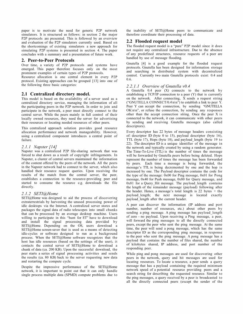
request). Similar to the ping/pong messages query messagesare also subject to hop increase and TTL decrease as a means oflimiting the range of the query message. Each message will bereplicated and propagated throughout the networks until i teither comes to a peer that matches the search criteria orexceeds its TTL value. Peers that are capable of offering therequested resource respond with a query_hit message. Aquery_hit message contains as payload information about theresource-providing peer.
Figure 2: The flat Gnutella 0.4 Network
Hence, a resource contained in the network is not searchable ifthe minimum distance (hops) between the peers is greater thanthe lifetime of the request. However, a resource located withinthe lifetime of the request might not be reachable as the resultof “short-circuiting” effect due to the latency of the network[11]. “Short-circuiting” effect occurs when there is a therequest with smaller lifetime arrived a node through thesmaller latency path, then when the same request with higherlifetime arrived through the higher latency path, this request i sdiscarded. (see Figure 2)
Pong messages, and query_hit, messages are routed along thesame path back to the peer that launched the original ping andquery messages. This is made possible by keeping a record of apredefined number of message descriptor Ids, and thecorresponding payload descriptors. When a peer received aresponse message (pong or query_hit), it will check if i tgenerated the original message (ping or query). If the peer i snot the destined receiver, it will check if it has seen such aping, or query, that has the descriptor id. If no such a ping, orquery, passed through the peer, the message will be dropped;else it will send the response message to the connection thatsent the corresponding ping, or query message. Once a peerreceived the Query_Hit message, generated by another peer, inresponse to its query message, it will access the resource usingthe http protocol.
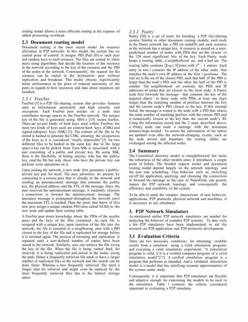
2.2.1.2 Gnutella v0.6 [12]Similar to Gnutella v0.4, a peer connects to the network byfirst establishing a link to another already connected peerthrough TCP/IP. The peer wishing to join sends the request toconnect string “GNUTELLA CONNECT/0.6<cr><lf>” andoptional data to describe itself thus making a connection morelikely.
Figure 3: Connection Request in 0.6.
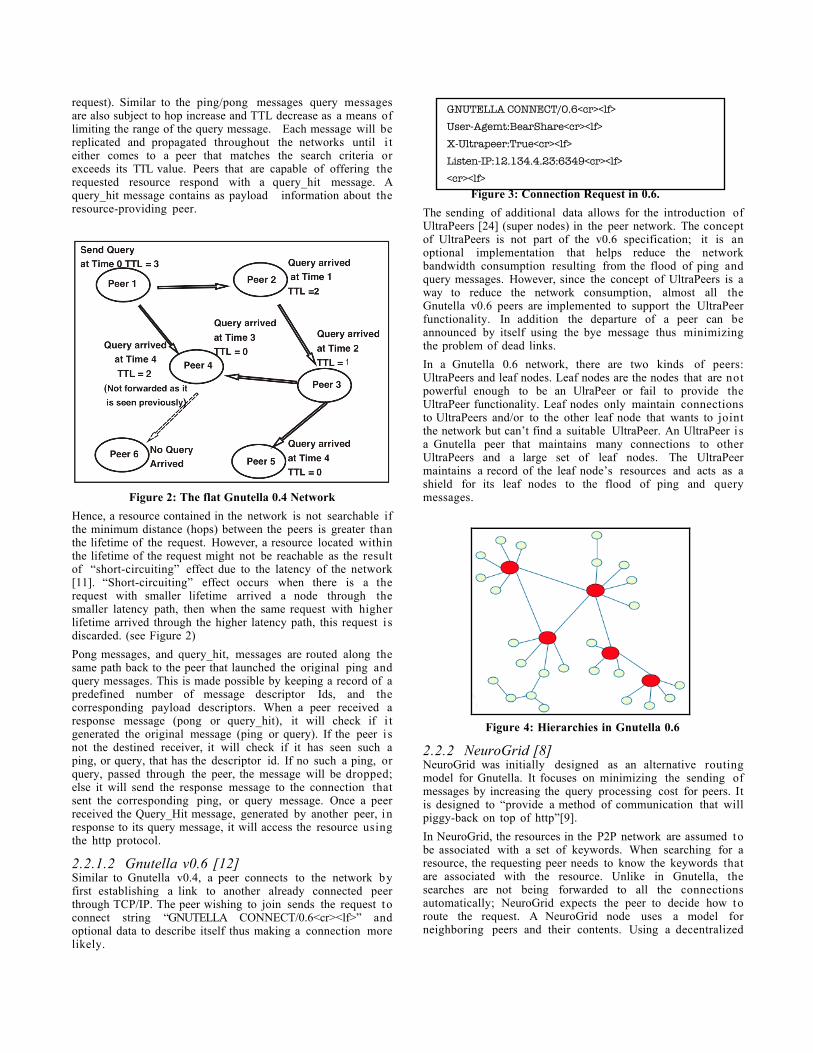
The sending of additional data allows for the introduction ofUltraPeers [24] (super nodes) in the peer network. The conceptof UltraPeers is not part of the v0.6 specification; it is anoptional implementation that helps reduce the networkbandwidth consumption resulting from the flood of ping andquery messages. However, since the concept of UltraPeers is away to reduce the network consumption, almost all theGnutella v0.6 peers are implemented to support the UltraPeerfunctionality. In addition the departure of a peer can beannounced by itself using the bye message thus minimizingthe problem of dead links.
In a Gnutella 0.6 network, there are two kinds of peers:UltraPeers and leaf nodes. Leaf nodes are the nodes that are notpowerful enough to be an UlraPeer or fail to provide theUltraPeer functionality. Leaf nodes only maintain connectionsto UltraPeers and/or to the other leaf node that wants to jointthe network but can’t find a suitable UltraPeer. An UltraPeer i sa Gnutella peer that maintains many connections to otherUltraPeers and a large set of leaf nodes. The UltraPeermaintains a record of the leaf node’s resources and acts as ashield for its leaf nodes to the flood of ping and querymessages.
Figure 4: Hierarchies in Gnutella 0.6
2.2.2 NeuroGrid [8]NeuroGrid was initially designed as an alternative routingmodel for Gnutella. It focuses on minimizing the sending ofmessages by increasing the query processing cost for peers. Itis designed to “provide a method of communication that willpiggy-back on top of http”[9].
In NeuroGrid, the resources in the P2P network are assumed tobe associated with a set of keywords. When searching for aresource, the requesting peer needs to know the keywords thatare associated with the resource. Unlike in Gnutella, thesearches are not being forwarded to all the connectionsautomatically; NeuroGrid expects the peer to decide how toroute the request. A NeuroGrid node uses a model forneighboring peers and their contents. Using a decentralized
routing model allows a more efficient routing at the expense ofadded processing overhead.
2.3 Document routing modelDocument routing is the most recent model for resourceallocation in P2P networks. In this model, the system has nocentral point of control. It assigns PID (Peer ID) to each peerand random keys to each resource. The files are routed to otherpeers using algorithms that decide the location of the resourcein the network according to the key of the resource and the PIDof the nodes in the network. Consequently, the request for theresource can be routed to the destination peer withoutreplication and broadcast. This model obtains significantlybetter performance at the price of reduced autonomy of thepeers in regards to how resources and data about resources arehandled.
2.3.1 FreeNetFreeNet [5] is a P2P file-sharing system that provides featuressuch as information anonymity and high security andencryption. Each FreeNet peer resides on a node thatcontributes storage spaces to the FreeNet network. The uniquekey of the file is generated using SHA-1 [15] secure hashes.There are several kinds of hash keys used within FreeNet; themain two kinds of keys used are content-hash keys (CHK) andsigned-subspace keys (SSK) [3]. The content of the file to bestored is hashed to generate the CHK, ensuring the uniquenessof the keys as it is considered “nearly impossible”[3] for twodifferent files to be hashed to the same key due to the largespace a key can be picked from. Each SSK is associated with apair consisting of a public and private key. By using SSK,there is the flexibility of letting anyone, who has the publickey, read the file but only those who have the private key canperform write operations on it.
Upon joining the network, a new node first generates a public-private key pair for itself. The peer advertises its present byconnecting to a remote peer that is already in the network andsending an announcement message that contains the publickey, the physical address, and the TTL of the message. Once thepeer received the announcement message, it randomly choosesa connection to forward the announcement message. Theannounce message is propagated throughout the network untilthe maximum TTL is reached. Then the peers that know of thisnew peer assign a unique random PID (also called GUID) to thenew node and update their routing table.
A FreeNet peer stores knowledge about the PIDs of the nearbypeers and the keys of the files contained. As each file i sassigned with a unique key, upon insertion of the file into thenetwork, the file is rerouted to a neighboring peer with a PIDclosest to the key of the file and is replicated for storage beforeit is rerouted again. The process of rerouting and replication i srepeated until a user-defined number of copies have beenstored in the network. Similarly, user can retrieve the file usingthe key of the file. When the file is being routed back forretrieval, it is being replicated and stored in the nodes alongthe path. Hence a frequently retrieved file tends to have a largernumber of replicated files in the network and the search can bedone faster. Whereas a less frequently retrieved file need alonger time for retrieval and might even be replaced by themore frequently retrieved files due to the limited storagespace.
2.3.2 PastryPastry [20] is a set of tools for building a P2P file-sharingsystem. Similar to other document routing models, each nodein the Pastry network has a PID (or nodeID) and each resourcein the network has a unique key. A resource is stored on a user-predefined number of nodes with PIDs that are the closest tothe 128 most significant bits of the key. Each Pastry nodekeeps a routing table, a neighborhood set, and a leaf set. Therouting table contains Èlog2b N˘ rows with 2b – 1 entries. Eachentry in row i contains the IP address of the other node, thatmatches the node’s own IP address in the first i positions. Theleaf set is the set of the closest PID, such that half of the PID i slarger than the node’s PID, and the other the half of the PID i ssmaller. The neighborhood set contains the PIDs and IPaddresses of nodes that are closest to the local node. A Pastrynode first forwards the message - that contains the key of thetargeted object - to those node with PIDs, at least one digitlonger than the matching number of prefixes between the keyand the current node’s PID, closest to the key. If this attemptfailed, the message is routed to the node with a PID that sharesthe same number of matching prefixes with the current PID andis numerically closest to the key than the current node’s ID.Using the information stored and the 2 steps described above,a Pastry node can route a message with the minimumdistance/hops needed. To ensure the information of the tablesare updated even after the network-changing events, such asthe node arrival and departure, the routing tables areexchanged among the affected nodes.
2.4 SummaryThe Centralized directory model is straightforward but lacksthe robustness of the other models since it introduces a singlepoint of failure. The flooded request model and documentrouting model depend largely on the network topology andthe user task scheduling. User behavior such as, switchingon/off the application, querying, and choosing the connectionto forward the message in the case of NeuroGrid, can greatlyimpact the P2P network topology and consequently theefficiency and scalability of the system.
To be able to study the complex interactions of user behavior,applications, P2P protocols, physical network and machines, i tis necessary to use simulators.
3. P2P Network SimulatorsAs mentioned earlier P2P network simulators are needed foranalyzing the behavior of complex P2P systems. To date onlya few P2P simulators have been implemented to aid theresearch on P2P-application and P2P-protocols development.
3.1 Evaluation CriteriaThere are two necessary conditions for obtaining credibleresults from a simulator: using a valid simulation program,and executing a valid simulation experiment. “A simulationprogram is valid, if it is a verified computer program of a validsimulation model”[17]. A verified simulation program is aprogram that performs as intended. And a validated simulationmodel is a model that has satisfying accurate approximation ofthe system under study.
Consequently it is important that P2P simulators are flexibleand adaptive enough for expressing the models to be used inthe simulation. Table 1 contains the criteria consideredimportant in evaluating a P2P simulator.
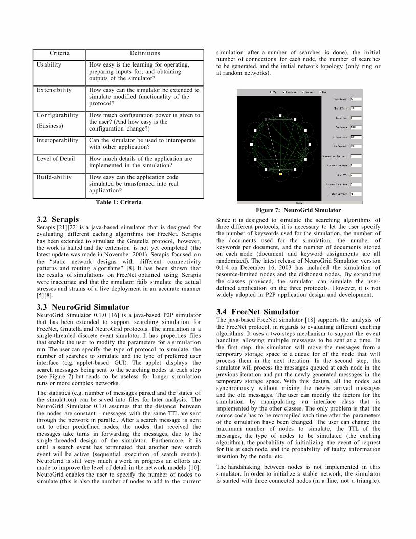
Criteria Definitions
Usability How easy is the learning for operating,preparing inputs for, and obtainingoutputs of the simulator?
Extensibility How easy can the simulator be extended tosimulate modified functionality of theprotocol?
Configurability
(Easiness)
How much configuration power is given tothe user? (And how easy is theconfiguration change?)
Interoperability Can the simulator be used to interoperatewith other application?
Level of Detail How much details of the application areimplemented in the simulation?
Build-ability How easy can the application codesimulated be transformed into realapplication?
Table 1: Criteria
3.2 SerapisSerapis [21][22] is a java-based simulator that is designed forevaluating different caching algorithms for FreeNet. Serapishas been extended to simulate the Gnutella protocol, however,the work is halted and the extension is not yet completed (thelatest update was made in November 2001). Serapis focused onthe “static network designs with different connectivitypatterns and routing algorithms” [8]. It has been shown thatthe results of simulations on FreeNet obtained using Serapiswere inaccurate and that the simulator fails simulate the actualstresses and strains of a live deployment in an accurate manner[5][8].
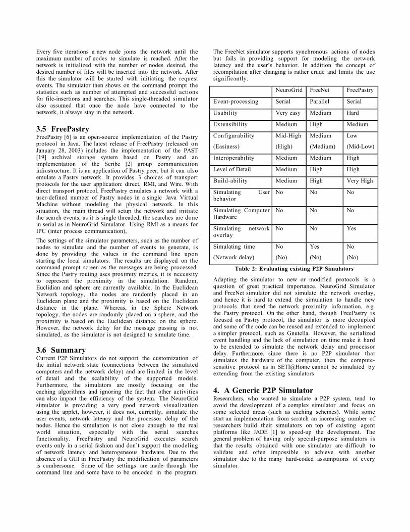
3.3 NeuroGrid SimulatorNeuroGrid Simulator 0.1.0 [16] is a java-based P2P simulatorthat has been extended to support searching simulation forFreeNet, Gnutella and NeuroGrid protocols. The simulation is asingle-threaded discrete event simulator. It has properties filesthat enable the user to modify the parameters for a simulationrun. The user can specify the type of protocol to simulate, thenumber of searches to simulate and the type of preferred userinterface (e.g. applet-based GUI). The applet displays thesearch messages being sent to the searching nodes at each step(see Figure 7) but tends to be useless for longer simulationruns or more complex networks.
The statistics (e.g. number of messages parsed and the states ofthe simulation) can be saved into files for later analysis. TheNeuroGrid Simulator 0.1.0 assumes that the distance betweenthe nodes are constant - messages with the same TTL are sentthrough the network in parallel. After a search message is sentout to other predefined nodes, the nodes that received themessages take turns in forwarding the messages, due to thesingle-threaded design of the simulator. Furthermore, it i suntil a search event has terminated that another new searchevent will be active (sequential execution of search events).NeuroGrid is still very much a work in progress an efforts aremade to improve the level of detail in the network models [10].NeuroGrid enables the user to specify the number of nodes tosimulate (this is also the number of nodes to add to the current
simulation after a number of searches is done), the initialnumber of connections for each node, the number of searchesto be generated, and the initial network topology (only ring orat random networks).
Figure 7: NeuroGrid Simulator
Since it is designed to simulate the searching algorithms ofthree different protocols, it is necessary to let the user specifythe number of keywords used for the simulation, the number ofthe documents used for the simulation, the number ofkeywords per document, and the number of documents storedon each node (document and keyword assignments are allrandomized). The latest release of NeuroGrid Simulator version0.1.4 on December 16, 2003 has included the simulation ofresource-limited nodes and the dishonest nodes. By extendingthe classes provided, the simulator can simulate the user-defined application on the three protocols. However, it is notwidely adopted in P2P application design and development.
3.4 FreeNet SimulatorThe java-based FreeNet simulator [18] supports the analysis ofthe FreeNet protocol, in regards to evaluating different cachingalgorithms. It uses a two-steps mechanism to support the eventhandling allowing multiple messages to be sent at a time. Inthe first step, the simulator will move the messages from atemporary storage space to a queue for of the node that willprocess them in the next iteration. In the second step, thesimulator will process the messages queued at each node in theprevious iteration and put the newly generated messages in thetemporary storage space. With this design, all the nodes actsynchronously without mixing the newly arrived messagesand the old messages. The user can modify the factors for thesimulation by manipulating an interface class that i simplemented by the other classes. The only problem is that thesource code has to be recompiled each time after the parametersof the simulation have been changed. The user can change themaximum number of nodes to simulate, the TTL of themessages, the type of nodes to be simulated (the cachingalgorithm), the probability of initializing the event of requestfor file at each node, and the probability of faulty informationinsertion by the node, etc.
The handshaking between nodes is not implemented in thissimulator. In order to initialize a stable network, the simulatoris started with three connected nodes (in a line, not a triangle).
Every five iterations a new node joins the network until themaximum number of nodes to simulate is reached. After thenetwork is initialized with the number of nodes desired, thedesired number of files will be inserted into the network. Afterthis the simulator will be started with initiating the requestevents. The simulator then shows on the command prompt thestatistics such as number of attempted and successful actionsfor file-insertions and searches. This single-threaded simulatoralso assumed that once the node have connected to thenetwork, it always stay in the network.
3.5 FreePastryFreePastry [6] is an open-source implementation of the Pastryprotocol in Java. The latest release of FreePastry (released onJanuary 28, 2003) includes the implementation of the PAST[19] archival storage system based on Pastry and animplementation of the Scribe [2] group communicationinfrastructure. It is an application of Pastry peer, but it can alsoemulate a Pastry network. It provides 3 choices of transportprotocols for the user application: direct, RMI, and Wire. Withdirect transport protocol, FreePastry emulates a network with auser-defined number of Pastry nodes in a single Java VirtualMachine without modeling the physical network. In thissituation, the main thread will setup the network and initiatethe search events, as it is single threaded, the searches are donein serial as in NeuroGrid Simulator. Using RMI as a means forIPC (inter process communication),
The settings of the simulator parameters, such as the number ofnodes to simulate and the number of events to generate, i sdone by providing the values in the command line uponstarting the local simulators. The results are displayed on thecommand prompt screen as the messages are being processed.Since the Pastry routing uses proximity metrics, it is necessityto represent the proximity in the simulation. Random,Euclidian and sphere are currently available. In the EuclideanNetwork topology, the nodes are randomly placed in anEuclidean plane and the proximity is based on the Euclideandistance in the plane. Whereas, in the Sphere Networktopology, the nodes are randomly placed on a sphere, and theproximity is based on the Euclidean distance on the sphere.However, the network delay for the message passing is notsimulated, as the simulator is not designed to simulate time.
3.6 SummaryCurrent P2P Simulators do not support the customization ofthe initial network state (connections between the simulatedcomputers and the network delay) and are limited in the levelof detail and the scalability of the supported models.Furthermore, the simulators are mostly focusing on thecaching algorithms and ignoring the fact that other activitiescan also impact the efficiency of the system. The NeuroGridsimulator is providing a very good network visualizationusing the applet, however, it does not, currently, simulate theuser events, network latency and the processor delay of thenodes. Hence the simulation is not close enough to the realworld situation, especially with the serial searchesfunctionality. FreePastry and NeuroGrid executes searchevents only in a serial fashion and don’t support the modelingof network latency and heterogeneous hardware. Due to theabsence of a GUI in FreePastry the modification of parametersis cumbersome. Some of the settings are made through thecommand line and some have to be encoded in the program.
The FreeNet simulator supports synchronous actions of nodesbut fails in providing support for modeling the networklatency and the user’s behavior. In addition the concept ofrecompilation after changing is rather crude and limits the usesignificantly.
NeuroGrid FreeNet FreePastry
Event-processing Serial Parallel Serial
Usability Very easy Medium Hard
Extensibility Medium High Medium
Configurability
(Easiness)
Mid-High
(High)
Medium
(Medium)
Low
(Mid-Low)
Interoperability Medium Medium High
Level of Detail Medium High High
Build-ability Medium High Very High
Simulating Userbehavior
No No No
Simulating ComputerHardware
No No No
Simulating networkoverlay
No No Yes
Simulating time
(Network delay)
No
(No)
Yes
(No)
No
(No)
Table 2: Evaluating existing P2P Simulators
Adapting the simulator to new or modified protocols is aquestion of great practical importance. NeuroGrid Simulatorand FreeNet simulator did not simulate the network overlay,and hence it is hard to extend the simulation to handle newprotocols that need the network proximity information, e.g.the Pastry protocol. On the other hand, though FreePastry i sfocused on Pastry protocol, the simulator is more decoupledand some of the code can be reused and extended to implementa simpler protocol, such as Gnutella. However, the serializedevent handling and the lack of simulation on time make it hardto be extended to simulate the network delay and processordelay. Furthermore, since there is no P2P simulator thatsimulates the hardware of the computer, then the compute-sensitive protocol as in SETI@Home cannot be simulated byextending from the existing simulators
4. A Generic P2P SimulatorResearchers, who wanted to simulate a P2P system, tend toavoid the development of a complex simulator and focus onsome selected areas (such as caching schemes). While somestart an implementation from scratch an increasing number ofresearchers build their simulators on top of existing agentplatforms like JADE [1] to speed-up the development. Thegeneral problem of having only special-purpose simulators i sthat the results obtained with one simulator are difficult tovalidate and often impossible to achieve with anothersimulator due to the many hard-coded assumptions of everysimulator.
In this section we present an architecture and implementationof a generic P2P simulator designed to overcome the problemsof existing simulators namely, extensibility, usability andlevel of detail.
4.1 GoalsThe criteria used to evaluate the simulators in section three areused as a guideline for the design of a more generic and opensimulator that will allow users to define models for thephysical network, physical machines, P2P topology, P2Pprotocol, P2P application and user behavior.
Gnutella v0.4 is being used for the example implementation ofthe protocol for simulation.
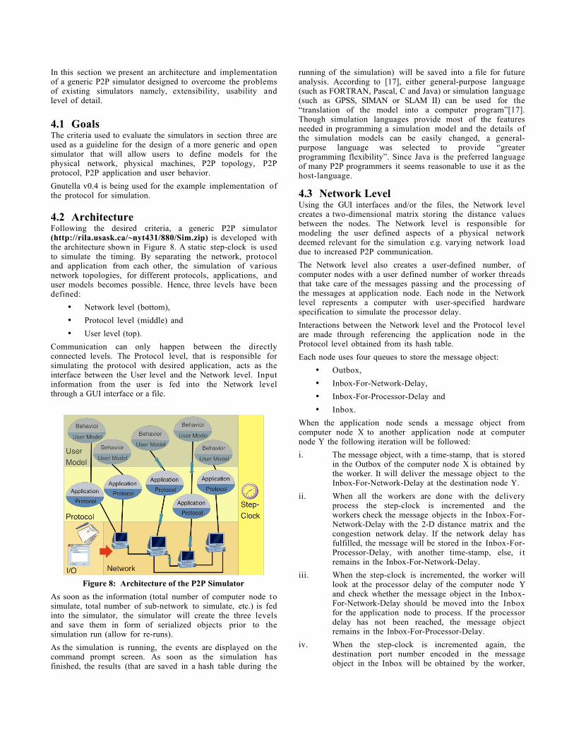
4.2 ArchitectureFollowing the desired criteria, a generic P2P simulator(http://rila.usask.ca/~nyt431/880/Sim.zip) is developed withthe architecture shown in Figure 8. A static step-clock is usedto simulate the timing. By separating the network, protocoland application from each other, the simulation of variousnetwork topologies, for different protocols, applications, anduser models becomes possible. Hence, three levels have beendefined:
• Network level (bottom),
• Protocol level (middle) and
• User level (top).
Communication can only happen between the directlyconnected levels. The Protocol level, that is responsible forsimulating the protocol with desired application, acts as theinterface between the User level and the Network level. Inputinformation from the user is fed into the Network levelthrough a GUI interface or a file.
Figure 8: Architecture of the P2P Simulator
As soon as the information (total number of computer node tosimulate, total number of sub-network to simulate, etc.) is fedinto the simulator, the simulator will create the three levelsand save them in form of serialized objects prior to thesimulation run (allow for re-runs).
As the simulation is running, the events are displayed on thecommand prompt screen. As soon as the simulation hasfinished, the results (that are saved in a hash table during the
running of the simulation) will be saved into a file for futureanalysis. According to [17], either general-purpose language(such as FORTRAN, Pascal, C and Java) or simulation language(such as GPSS, SIMAN or SLAM II) can be used for the“translation of the model into a computer program”[17].Though simulation languages provide most of the featuresneeded in programming a simulation model and the details ofthe simulation models can be easily changed, a general-purpose language was selected to provide “greaterprogramming flexibility”. Since Java is the preferred languageof many P2P programmers it seems reasonable to use it as thehost-language.
4.3 Network LevelUsing the GUI interfaces and/or the files, the Network levelcreates a two-dimensional matrix storing the distance valuesbetween the nodes. The Network level is responsible formodeling the user defined aspects of a physical networkdeemed relevant for the simulation e.g. varying network loaddue to increased P2P communication.
The Network level also creates a user-defined number, ofcomputer nodes with a user defined number of worker threadsthat take care of the messages passing and the processing ofthe messages at application node. Each node in the Networklevel represents a computer with user-specified hardwarespecification to simulate the processor delay.
Interactions between the Network level and the Protocol levelare made through referencing the application node in theProtocol level obtained from its hash table.
Each node uses four queues to store the message object:
• Outbox,
• Inbox-For-Network-Delay,
• Inbox-For-Processor-Delay and
• Inbox.
When the application node sends a message object fromcomputer node X to another application node at computernode Y the following iteration will be followed:
i. The message object, with a time-stamp, that is storedin the Outbox of the computer node X is obtained bythe worker. It will deliver the message object to theInbox-For-Network-Delay at the destination node Y.
ii. When all the workers are done with the deliveryprocess the step-clock is incremented and theworkers check the message objects in the Inbox-For-Network-Delay with the 2-D distance matrix and thecongestion network delay. If the network delay hasfulfilled, the message will be stored in the Inbox-For-Processor-Delay, with another time-stamp, else, i tremains in the Inbox-For-Network-Delay.
iii. When the step-clock is incremented, the worker willlook at the processor delay of the computer node Yand check whether the message object in the Inbox-For-Network-Delay should be moved into the Inboxfor the application node to process. If the processordelay has not been reached, the message objectremains in the Inbox-For-Processor-Delay.
iv. When the step-clock is incremented again, thedestination port number encoded in the messageobject in the Inbox will be obtained by the worker,
and the reference to the application node will beobtained to send the message object to theapplication node for process. After the applicationnode processed the received message object, it willcheck the hash table that contains the scheduled taskfor execution. Any created message object is storedin the Outbox and the iteration is repeated from (i)when the step clock is incremented again.
The simulator follows the 2-steps mechanism: for each unit ofuser-time, it takes 2 step-times in the simulation (the stepclock is incremented twice). Hence, in the first step-time,iteration step ii and iv are executed. In the second step-time,iteration step i and iii are executed. With this design, thenetwork delay and processor delay can be simulated, and thereis no mixing up of the order of the message arrived at eachbox. And most importantly, this enables several tasks (orevents) being carried out at any time.
4.4 Protocol LevelA Peer class is used to provide an interface for the workers inthe network level and to enable the sending of messages from acomputer node to an application node. Any protocolimplementation has to implement this Peer interface class.
In the example implementation the GnutellaPeer class takescare of the Gnutella v0.4 protocol level issues, such as keepingtrack of the connection between the peers by keeping a table ofthe IP address and the port number of the directly connectedpeers. Though it can be used as the application node, it is notproviding much for the application level. An application canbe easily built by extending the protocol class by overridingthe message processing methods.
Reflection is used for the creation of application nodes usingdata specified by the user. The user needs to specify the IPaddress and port number of the peers created. Upon beingcreated, the application node/peer can use the Registrationclass provided by the Network level to register itself to port ofthe computer node using the IP address provided.
The implementation of the message object is very important inthis simulator. The message object contains the time-stamp,reference to the message content object, the origin’s IP addressand port number, and the destination IP address and portnumber. An instance of the Communication class (messageobject) represents packet sent through the connectionsbetween the connected computer nodes. A Gnutella peer firstcreates an instance of the type of the message desired to besent and then creates an instance of the class Communicationto store the reference of the message instance. Then the peersends the Communication instance as a message object usingthe Registration class.
4.5 User LevelUnlike the other levels the User level has not beenimplemented in the current version of the generic P2Psimulator. A UserModel class contains the method signaturesfor the decision-making needed from the Protocol level. Itshould have a reference back to the Peer instance. Uponcreation and referenced to the associated Peer, it should addthe tasks into the tasks scheduler in the Peer instance. EachPeer instance should have an instance of the UserModel class,as the behavior of the user with the same UserModel can bedifferent due to the Peer’s performance. When the instance of
UserModel is consulted, it should check its states and when anevent is to be initiated, it should add the task into the taskscheduler in the Peer instance at the protocol level byreferencing the current time with the static step-clock.
4.6 EvaluationIn its current Java 1.3.1 implementation, the simulatorconsists of 29 classes with approximately 3599 lines of code.There are 10 classes (899 lines of code) for Platform level, 12classes (508 lines of code) for Gnutella Protocol with user taskscheduling, and 7 classes (2159 lines of code) for GUIinterfaces including the main method class.
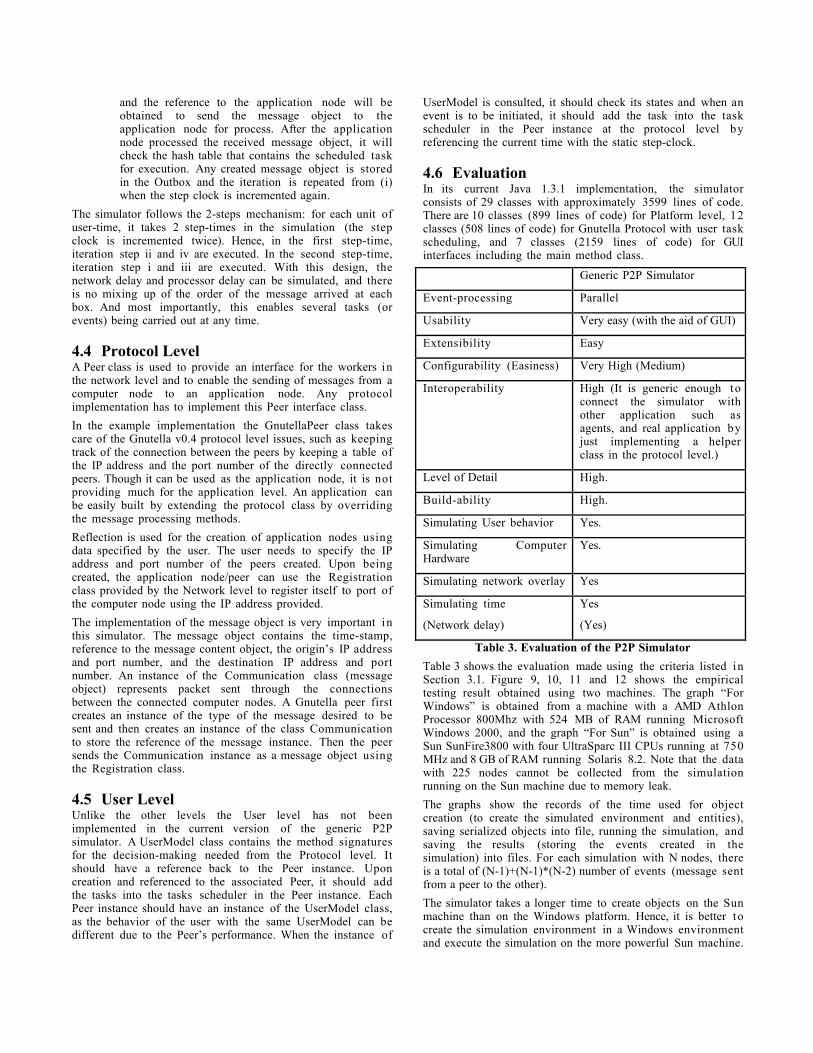
Generic P2P Simulator
Event-processing Parallel
Usability Very easy (with the aid of GUI)
Extensibility Easy
Configurability (Easiness) Very High (Medium)
Interoperability High (It is generic enough toconnect the simulator withother application such asagents, and real application byjust implementing a helperclass in the protocol level.)
Level of Detail High.
Build-ability High.
Simulating User behavior Yes.
Simulating ComputerHardware
Yes.
Simulating network overlay Yes
Simulating time
(Network delay)
Yes
(Yes)
Table 3. Evaluation of the P2P Simulator
Table 3 shows the evaluation made using the criteria listed inSection 3.1. Figure 9, 10, 11 and 12 shows the empiricaltesting result obtained using two machines. The graph “ForWindows” is obtained from a machine with a AMD AthlonProcessor 800Mhz with 524 MB of RAM running MicrosoftWindows 2000, and the graph “For Sun” is obtained using aSun SunFire3800 with four UltraSparc III CPUs running at 750MHz and 8 GB of RAM running Solaris 8.2. Note that the datawith 225 nodes cannot be collected from the simulationrunning on the Sun machine due to memory leak.
The graphs show the records of the time used for objectcreation (to create the simulated environment and entities),saving serialized objects into file, running the simulation, andsaving the results (storing the events created in thesimulation) into files. For each simulation with N nodes, thereis a total of (N-1)+(N-1)*(N-2) number of events (message sentfrom a peer to the other).
The simulator takes a longer time to create objects on the Sunmachine than on the Windows platform. Hence, it is better tocreate the simulation environment in a Windows environmentand execute the simulation on the more powerful Sun machine.
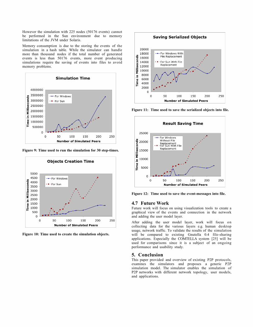
However the simulation with 225 nodes (50176 events) cannotbe performed in the Sun environment due to memorylimitations of the JVM under Solaris.
Memory consumption is due to the storing the events of thesimulation in a hash table. While the simulator can handlemore than thousand nodes if the total number of generatedevents is less than 50176 events, more event producingsimulations require the saving of events into files to avoidmemory problems.
Figure 9: Time used to run the simulation for 30 step-times.
Figure 10: Time used to create the simulation objects.
Figure 11: Time used to save the serialized objects into file.
Figure 12: Time used to save the event-messages into file.
4.7 Future WorkFuture work will focus on using visualization tools to create agraphical view of the events and connection in the networkand adding the user model layer.
After adding the user model layer, work will focus oncollecting data for the various layers e.g. human desktopusage, network traffic. To validate the results of the simulationwill be compared to existing Gnutella 0.4 file-sharingapplications. Especially the COMTELLA system [25] will beused for comparisons since it is a subject of an ongoingperformance and usability study.
5. ConclusionThis paper provided and overview of existing P2P protocols,examines the simulators and proposes a generic P2Psimulation model. The simulator enables the simulation ofP2P networks with different network topology, user models,and applications.
6. REFERENCES[1] Bellifemine, F., Poggi, A., Rimassa, G. JADE–A FIPA-
compliant agent framework In Proceedings of PAAM'99,London, April 1999, 97-108.
[2] Castro, M., Druschel, P. Kermarrec A-M., Rowstron A.SCRIBE: A large-scale and decentralised application-levelmulticast infrastructure. IEEE Journal on Selected Areas inCommunications (JSAC) (Special issue on NetworkSupport for Multicast Communications), to appear, 2002.
[3] Clarke, I., Miller, S. G., Hong, T. W., Sandberg, O., Wiley, B.Protecting Free Expression Online with Freenet. IEEEInternet Computing 6(1), 40-49 (2000).
http://freenetproject.org/twiki/Main/Papers/ieee-final.pdf
[4] Clip2. The Gnutella Protocol Specification v0.4.
http://rfc-gnutella.sourceforge.net/Development/GnutellaProtocol0_4-rev1_2.pdf
[5] FreeNet. The FreeNet homepage, freenet.sourceforge.net.
http://freenetproject.org/cgi-bin/twiki/view/Main/WhatIs
[6] FreePastry. The FreePastry homepage.
http://www.cs.rice.edu/CS/Systems/Pastry/FreePastry/
[7] Fried, I. Intel chip will be bigger, more expensive to make.Cnet News.com, June 2002.
http://news.com.com/2100-1001-241376.html?tag=mainstry
[8] Joseph, S.R.H. Adaptive Routing in DistributedDecentralized Systems: NeuroGrid, Gnutella, and Freenet.Proceedings of workshop on Infrastructure for Agents,MAS, and Scalable MAS, at Autonomous Agents,Montreal, Canada, 2001.
[9] Joseph, S.R.H. NeuroGrid Protocol.
http://www.neurogrid.net/ng-protocol.html.
[10] Joseph, S.R,H. Project:NeuroGrid -P2P BookmarkOrganiser:Mailing Lists. NeuroGrid Simulation MailingArchive, Jan 2003
http://sourceforge.net/mailarchive/forum.php?thread_id=1593250&forum_id=8271
[11] Jovanovic, M. A. Modeling Large-scale Peer-to-PeerNetworks and a Case Study of Gnutella. M. Sc. Thesis,University of Cincinnati, 2001.
[12] Klingberg, T., Manfredi, R. Gnutella 0.6.
http://rfc-gnutella.sourceforge.net/draft.txt
[13] Milojicic, D. S., Kalogeraki, V., Lukose, R., Nagaraja, K.,Pruyne J., and Richard, B. Peer-to-Peer Computing.Internal Report HP, March 8.
http://www.hpl.hp.com/techreports/2002/HPL-2002-57.html
[14] Napster. The Napster homepage.
http://www.napster.com
[15] National Institute of Standards and Technology. SecureHash Standard (SHS).
http://csrc.nist.gov/cryptval/shs.html
[16] NeuroGrid. The NeuroGrid homepage.
http://www.neurogrid.net/
[17] Pawlikowski, K. Simulation Modeling and Analysis withan emphasis on applications in performance evaluation oftelecommunication networks. Course 410, University ofCanterbury, August 2002.
http://www.cosc.canterbury.ac.nz/teaching/handouts/cosc410/02.410.notes1.pdf
[18] Pfeifer, J. Freenet Caching Algorithms Under High Load.
http://www.cs.usask.ca/classes/498/t1/898/W7/P2/freenet.pdf
[19] Rowstron, A., Druschel, P. PAST: A large-scale, persistentpeer-to-peer storage utility. HotOS VIII, Schoss Elmau,Germany, May 2001.
[20] Rowstron, A., Druschel, P. Pastry: Scalable, decentralizedobject location and routing for large-scale peer-to-peersystems IFIP/ACM international Conference onDistributed Systems Platforms (Middleware), Heidelberg,Germany, 329-350, November 2001.
http://research.microsoft.com/~antr/PAST/pastry.pdf
[21] Sandberg, O. The FreeNet-dev mailing list, March 2001
http://www.ultraviolet.org/mail-archives/freenet-chat.2001/0354.html
[22] Serapis. The Serapis homepage, cvs. Sourceforge.net.
http://cvs.sourceforge.net/cgi-bin/viewcvs.cgi/freenet/Serapis/
[23] SETI@Home. The SETI@Home homepage.
http://setiathome.ssl.berkeley.edu/
[24] Single, A., Rohrs, C. Ultrapeers: Another Step TowardsGnutella Scalability.
http://www.limewire.com/developer/Ultrapeers.html
[25] Vassileva, J. Motivating participation in Peer to PeerCommunities. Proceeding of Workshop on EmergentSocieties in the Agent World, ESAW’02, Madrid, 16-17September, 2002.
http://www.ai.univie.ac.at/%7Epaolo/conf/esaw02/preproc/E0029.pdf