Embed Size (px)
Citation preview

IMPACT LABORATORY
IMPROVING MANUFACTURING PRODUCTIVITY WITH ADVANCED COLLABORATION TECHNOLOGY
A Generic Collaborative Engineering Design Process Model for Conflict Management
By
Lu, S. C.-Y. and Cai, J.
Department of Aerospace and Mechanical Engineering University of Southern California
Los Angeles, CA 90089-1111
IMPACT WORKING PAPER No. WP00-03
2000
UNIVERSITY OF SOUTHERN CALIFORNIA
A Generic Collaborative Engineering Design Process Model for Conflict Management
Stephen. C-Y. Lu, Jian Cai1
The IMPACT Research Laboratory, University of Southern California, Los Angeles, CA 90089, USA
Fax: 1 (213) 740 6668, Email: [email protected]
Manuscript Pages: 32
Tables: 1
Figures: 13
1 Correspondence and reprint requests to: Jian Cai, The IMPACT Laboratory, Suite 101, Denney Research Building, University of Southern California, Los Angeles, CA90089-1111

Abstract
Collaborative engineering design involves various stakeholders with different perspectives. The design process is
relatively complex and difficult to handle. Various conflicts always happen among the design tasks and affect the
design team performance. Therefore, to represent collaborative design process and capture the evolution of design
perspectives in a structured way is critical to manage the design conflicts and improve the collaborative design
productivity. This paper provides a generic design collaborative design process representation model based on a
Socio-Technical design framework. This model has a topological format and adopts process analysis techniques
from Petri Nets. By addressing both the technical and social aspects of collaborative design activities, it provides a
mechanism to identify the interdependencies among design tasks and perspectives of different stakeholders. Based
on this design process model, a methodology of detecting and handling the design conflicts is developed to support
collaborative design coordination.
Keywords : Design Process Representation; Collaborative Design; Petri Nets; Conflict Management

1. Introduction
The increasing complexity of modern production makes design process more and more difficult to handle since
numerous technical and social issues are involved. The design activities are influenced not only by the technological
factors but also the interactions among various stakeholders with different perspectives. To deal with this
challenging problem requires an effective collaborative design process model, which can clearly depict the
characteristics of collaborative design activity and provide methodologies to improve design productivity.
Traditionally, there are a lot of approaches dealing with different elements of engineering design process from
various perspectives. They can be generally classified to three groups. The first group, which is mainly from the
engineering discipline, focuses on investigation of how the technical design decisions are made and generating
formalized design methodologies. Design process models are often implied in these design theories and
methodologies, such as Systematic design model (Paul & Beitz, 1996), Axiomatic design model (Suh, 1990), QFD
(Hauser & Clausing, 1988), General design theory (Yoshikawa, 1981), etc. Basically, these design methodologies
provide the guidelines for designer to make technical decisions more consciously and systematically (Jin & Lu,
1998). The second group views design process as workflow with task dependencies and information exchange.
Approaches in this category are mainly from the research of business operation and project management. From this
aspect, design is viewed as an information driven process among design activities. Design organization is viewed as
a stochastic processing network in which engineering resources are “workstations” and design tasks are “jobs” that
flow among them (Adler & Mandelbaum, 1995; Sanvido & Norton, 1994). Accordingly, a set of techniques to
manipulate the design activities has been developed, such as signal flow (Eppinger, 1997) and design process
network (Bras & Mistree, 1991). Besides the above two groups, several research approaches from CAD and CAE
areas view collaborative design as individuals and groups accessing data and sharing the design information. Design
process is accordingly specified as the managing of the product data in different abstraction levels. During this
process, the technological, scientific, and interdisciplinary dependencies of the information could be established and
maintained by handling the product model (Majumder et al., 1994). The information systems built by them are to
support the storage and processing of various types of data interested by designers (Sriram et al., 1997;
Krishnamurthy & Law, 1997).

These three classes of approach focus on different aspects of design and provide considerable contributions for
understanding design characteristics. Design theory research provides a clearer picture of design rationale and
decision making process. Design activity manipulation furnishes characterizing design operations and identifying
the dependencies of design tasks in the organization. Design data management supports information storage and
access typically in design automation. However, it is noticed that these traditional approaches have their own
limitations when applied in collaborative design. These approaches normally assume the indifference of perspectives
of different stakeholder and ignore their social interactions. Design process is accordingly viewed as a series of pure
technical activities, and the key issue “who” is not explicitly addressed. In fact, it is impossible to completely share
the knowledge and purpose among designers in collaborative design. Rather than being pure rationale, stakeholders
have an optimal or satisfied degree of consensus, which provides the desirable design result. Although design
methodologies and workflow management techniques are applied, designers still face some failures of coordination
due to their perspective differences and the inefficient design process management.
Therefore, a more comprehensive view is required to clarify the relationships among various technical and social
aspects of collaborative design. Collaborative design process model based on this perception will generate effective
coordination mechanisms for task planning, scheduling and monitoring, for detecting and managing design conflicts
and for tracking and controlling design roles of stakeholders. This paper describes a generic collaborative design
process model based on a Socio-Technical design framework, which is suitable to represent, analyze and evaluate
the collaborative design activities. We use Petri Nets as topological process modeling tools and adapts it for
collaborative design process modeling. A methodology of design conflict management is developed with the design
process representation model. The outline of this paper is as follows. In Section 2, we discuss the fundamental issues
of collaborative design process modeling and introduce a Socio-Technical design process modeling architecture.
Then the basics of collaborative design process representation model are described in Section 3. Section 4 presents a
methodology to manage design conflict by using the collaborative design process model. After that a prototype
collaborative design support system, which is a computer implementation of the methodology, is discussed. At the
end, Section 6 offers conclusion and future research issues.

2. Characteristics of Collaborative Design Process
The central objective of engineering design is to achieve the prospective artificial objects having desired
properties. As pointed by Herbert Simon, an artifact can be thought of as a meeting point – an “interface” between
an “inner” environment, the substance and organization of the artifact itself, and an “outer” environment, the
surroundings in which it operates (Simon, 1996). During the design process, it is design stakeholders’ task to define
the features within the inner environment of the product (e.g. form, structure, and behavior), which should be
appropriate to its outer environment. Due to the involvement of human being, design process is not only based on
the nature law of the artifact but also influenced by people’s goals, skills, and circumstances. Therefore, within the
collaborative design process, design information is driven by social, technological, scientific, and inter-disciplinary
dependencies. Design process is therefore should be modeled by revealing the complicated relationships among
them. We proposed a Socio-Technical Design framework to address the fundamental characteristics of collaborative
design process.
2.1 Technical decision and Social interaction
In collaborative design, stakeholders (e.g. customer, manager, and design engineer) participate into design
campaign with both technical roles and social roles. Based on their roles, the ways stakeholders understand design
and manipulate the activity are non-uniform. They usually adjust the attitudes based on the feedback from others.
Design process is thus consisted with not only technical decision making but also social interaction. That means the
representation of design process should consider the dynamics of perspectives of the individuals. Without realization
of variances of roles and perspectives among the stakeholders during design interaction, it is difficult to identify and
manage the various design conflicts. However, traditional design process models do not address design perspectives
and their social interaction. They either ignore the social features of design or assume designers are purely rationale
and simplify their preference as utility values.
The important negotiations among the collaborative design decisions are about “why” and “who” besides “what”
and “how”. We believe a well-formed collaborative design process model has to facilitate the stakeholders to realize
the perspective difference with each other and support them to detect and evaluate the inter-dependencies and
resolve conflicts. Besides keeping the product data integrity, design information system should provide the

“language” or “medium” for design participants to declare and depict their perspectives and aid their
communication. These will definitely affect the current design organization structure and design process. Therefore,
it is critical to generate a design process representation model, which can facilitate the describing, tracing, and
management of collaborative design interactions.
2.2 Design Perspectives
Defining design perspective is one of the essential issues in design process modeling. In collaborative design,
stakeholders’ perspectives can be visualized as “lenses” they wearing during design process. Each stakeholder has
his/her unique viewpoints and circumstances, which further define their roles in the design campaign. For the same
object, they may have different perceptions and make different decisions. In the Socio-Technical framework a
perspective is defined as the combination of:
• a purpose with which the stakeholder participates in an engineering design campaign;
• a context within which the stakeholder participates in an engineering design campaign; and
• a content relevant to the purpose and context, i.e., the experience, background, education, knowledge, an
insight that the stakeholder brings to bear within an engineering design campaign.
Collaborative design process is also a perspective evolution process. At the start of design, it is obvious that the
“what”, “how”, “when”, “where” and “why” are interpreted differently by different perspectives. During design, the
participants and the organization interact together and build the shared reality (Berger & Luckman, 1966) (i.e. the
institutional understanding of the world) in the social interaction process. While a technical design process model
(e.g. Axiomatic Design Model) may serve as a basis or starting point for technical decision making, it is always
dynamically adapted and modified by the participants during the course of the design campaign. The design
perspectives of the stakeholders are affected and the shared reality is formed while the function, form and behavior
of the product are being defined. It should be pointed out that most of the conflicts in the collaborative design are
caused by the discord among the stakeholders’ perspectives. Therefore, to represent the perspectives of the
stakeholders and investigate their influence to the design process is indispensable in design process modeling and
conflict management.
2.3 Coordination among stakeholders
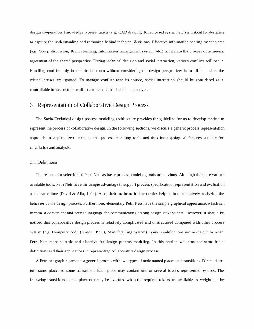
Collaborative design problems are usually complex and have to be decomposed to sub-problems, which are often
assigned to different individuals separately. Although some design methodologies suggest designers to increase the
probability of success by maintaining the independence of sub-problems (e.g. Axiomatic Deign Model), it is
difficult to achieve in collaborative design due to the various dependencies among tasks. On the other hand,
individuals normally have limited capability to identify the influences of their decisions to others. Due to lack of
coordination effort, the meanings about design objects might not be defined well, especially at the conceptual design
stage. All of the above makes the decomposition and integration of design sub-problems a rather complicated
analyzing and synthesizing process. In collaborative design, integration has to be achieved not only through the
communication of contents, but also through communication about the creation and evolution of shared meaning.
The shared meaning is always defined by the interaction of design perspectives. That reveals one of the essential
aspects of collaborative design process modeling, which is to represent and manage the interactions among the
individuals’ perspectives during this decomposition and synthesis process. In collaborative design process, the
influence of one’s decision making in specific domain to others’ decision making in different sub-problems should
be represented and evaluated. Furthermore, the design process representation model has to help design stakeholders
to detect and evaluate the inter-dependencies among their design activities and solve conflicts. Therefore, design
coordination relates to not only the dependency identification among the design decisions, but also the management
of changing and interaction of the design stakeholders’ perspectives.
2.4 Socio-Technical design process architecture We believe collaborative design process should be modeled in a comprehensive picture, which includes not only
the technical elements but also the social issues. It is necessary to have a design process model, which can represent
and keep track of the state of collaborative design (e.g. the solved problem and the coming problem, the changing
product model, and the evolving perspectives of different stakeholders). Also, the negotiation and interaction pattern
among the stakeholders’ design perspectives should be explicitly represented and captured. These requirements are
the major differences between the design process models dealing with collaboration and those for individual design.

Detection
Resolution
Intervention
Causes Effects Context
Perspective
Purpose Context Content
Technical Role
Social Role
KnowledgeRepresentation
Information sharing
Function Structure Behavior Norm/Culture Procedure Form
Meaning will be defined
Consist of
Inter-link
mutual influence mutual influence
responsible for
Mut
ual i
nflu
ence
manage
participate
play play
design
represent
has view of
drive/change within/
generate Organization IntegratedProduct Model
TechnicalDecisions
SocialInteraction
Stakeholder
Conflict
ConflictManagement
Figure 1 The Socio-Technical design process architecture
The Socio-Technical design process architecture provides a more comprehensive view to model collaborative
design process (Lu et al., 1999). In Figure 1, the different elements and their relationships in collaborative design are
clearly depicted. From the Socio-Technical viewpoint, technical decisions , social interaction, and conflict
management are the tree essential elements in collaborative design process. In a design campaign, stakeholders
perform both technical roles and social roles. The former is conducted in the technical decision-making process and
the latter is in the social interaction. Normally, the characteristics of the design problem and the perspectives of the
stakeholders predetermine their technical roles. However, they are not static during the design process. In most
situations, their roles are adaptive while the perspectives evolve. That will also go back to influence the technical
decision making process. By making technical decisions based on their technical roles, design stakeholders create,
modify and evaluate the product features. Since the involvement of social roles, which are normally influence by the
organization structure, norm, and culture, technical decisions are coupled with the social-interactions during the
design cooperation. Knowledge representation (e.g. CAD drawing, Ruled based system, etc.) is critical for designers
to capture the understanding and reasoning behind technical decisions. Effective information sharing mechanisms
(e.g. Group discussion, Brain storming, Information management system, etc.) accelerate the process of achieving
agreement of the shared perspective. During technical decision and social interaction, various conflicts will occur.
Handling conflict only in technical domain without considering the design perspectives is insufficient since the
critical causes are ignored. To manage conflict near its source, social interaction should be considered as a
controllable infrastructure to affect and handle the design perspectives.
3 Representation of Collaborative Design Process
The Socio-Technical design process modeling architecture provides the guideline for us to develop models to
represent the process of collaborative design. In the following sections, we discuss a generic process representation
approach. It applies Petri Nets as the process modeling tools and thus has topological features suitable for
calculation and analysis.
3.1 Definitions
The reasons for selection of Petri Nets as basic process modeling tools are obvious. Although there are various
available tools, Petri Nets have the unique advantage to support process specification, representation and evaluation
at the same time (David & Alla, 1992). Also, their mathematical properties help us in quantitatively analyzing the
behavior of the design process. Furthermore, elementary Petri Nets have the simple graphical appearance, which can
become a convenient and precise language for communicating among design stakeholders. However, it should be
noticed that collaborative design process is relatively complicated and unstructured compared with other process
system (e.g. Computer code (Jenson, 1996), Manufacturing system). Some modifications are necessary to make
Petri Nets more suitable and effective for design process modeling. In this section we introduce some basic
definitions and their applications in representing collaborative design process.
A Petri net graph represents a general process with two types of node named places and transitions. Directed arcs
join some places to some transitions. Each place may contain one or several tokens represented by dots. The
following transitions of one place can only be executed when the required tokens are available. A weight can be

associated with each transition, which is a positive number. The marking of the Petri net is a vector that contains the
values of marking in all places.
In collaborative design process, place and transition are equal to “event” and “task” respectively. Design process
is represented by an organization of places and transitions. The weights of the tasks can be used to represent their
resource consumption. The default value of the weight is one. The arcs represent the transform directions between
events and tasks during the design. The token denotes the state of each individual event. Event contains token if and
only if it is active (i.e. event is happening). Thus the whole state of design process can be expressed by a marking
M , which is a vector having the token numbers of each event in design process. Since different stakeholders can
conduct tasks, we introduce the “stakeholder” into the notation. Each task and event has a set of stakeholders
associated. Formally, a Collaborative Design Process can be represent by a Petri net graph with the following
definitions.
Definition 1: A Collaborative Design Process Net (CDPN) is a tuple ),,,,,( MWASTECDPN = with a
set of labels:
},...,,{ 21 neeeE = is a finite set of design events,
},...,,{ 21 qtttT = is a finite set of design tasks,
},...,,{ 21 msssS = is a finite set of design stakeholders,
)}(){( ETTEA ××⊆ U is a finite set of directed arc connecting event and task,
},...,,{: 21 pwwwTW → is weight function attached to the design task,
,...}2,1,0{:0 →EM is the initial marking.

E1
E2
E3
E6E5
E4
T1
T2
T3 T4
T5
Beginning marketinginvestigation
Start of environment design
Select Buildinglocation
S1, S2 S2 S1,S2
S1, S3 S3 S1, S3
Preliminary Building location Selected
Gather customer needs
Investigation reportsubmission
Identify building requirements Draw preliminary
building layout
Revise layout
Layout check
Start layout designS2, S4 S4
S1,S4
S1, S4
S1,S2,S4
Figure 2 An example of Collaborative Design Process Net
As shown in the example (Figure 2), a portion of building design process is represented in a graph with the
above elements. To explicitly address the stakeholders in design process, each event and task has a set of
stakeholders associated. We use 4321 ,,, SSSS to denote project manager, design consultant, market surveyor, and
architect respectively, which are marked on top of the events and tasks. At the beginning of design, the tokens are
only contained in the start events (E1 and E2). After stakeholders preformed the tasks, the tokens from the upward
events can be transferred to the downward events. 0M is defined as the initial marking of a CDPN, which is a
vector contains the token number for each events. For instance, at the beginning of design 0M = [1 1 0 0 0 0 0]
since only event 1 and 2 possess tokens. If 0M equals [0 0 0 0 0 0 1], that means the all of the tasks shown in the
graph have been conducted since the token is presented in the last event.
The input and output relationships between task and events are denoted as:
to the set of input events of task t, (i.e. the set of }),(|{ Atee ∈
ot the set of output events of task t, (i.e. the set of }),(|{ Aete ∈

eo the set of input tasks of event e, (i.e. the set of }),(|{ Aett ∈
oe the set of output tasks of event e, (i.e. the set of }),(|{ Atet ∈
It is clear that finishing a task t consists with transforming the initial marking 0M of the CDNP into a new
marking M . Firing a task Tt ∈ includes two operations, which are removing a token from each te o∈ and adding
a token to each ote ∈ (assuming each arc has weight one). It could be formally defined as follows:
Definition 2: A task can be fired in a state 0M iff 0)(: 0 >∈∀ eMte o . The firing of a task leads to the next
state M , which can be calculated by:
∈+∈−
=otherwise )(
if 1)( if 1)(
)(
0
0
0
eMteeMteeM
eM o
o
(3.1)
Thus the execution of design process are represented by a task firing sequence >=< ,..., 21 ttσ , which relates
to a transformation of the marking 0M àM .
Process incidence matrix ][ , jiuU = is defined to represent the relationship between tasks and events.
Definition 3: An incidence matrix ][ , jiuU = is defined over all of the events },...,,{ 21 neeeE = , and tasks
},...,,{ 21 qtttT = where
∈−∈
=otherwise 0
if 1 if 1
,o
o
ij
ij
ji etet
u (3.2)
For example the ( qn × ) incidence matrix of the above graph is
−−
−−
−−
=
110001110000110001010001000001
U
Incidence matrix captures the interdependencies among the tasks and events. The relationship between state
transformation and incidence matrix can be expressed in the following transformation equation:

Proposition 1: TTT VUMM σ•+= 0 (3.3)
Where ],...,,[ 21 qvvvV =σ is a counting vector for a task firing sequence defined as:
Definition 4: The counting vector of firing sequence σ is defined as ],...,,[ 21 qvvvV =σ , where iv is the
number of tasks it included in σ .
Given the firing sequence σ =< T1, T2, T3, T4, T5, T4> in the example, its counting vector σV equals
[1 1 1 2 1]. Based on the equation (3.3), the final marking can be calculated as follows.
=
−−
+
=
−−
−−
−−
+
=
100000
100011
000011
12111
110001110000110001010001000001
000011
TM
M =[0 0 0 0 0 0 1] shows only event 6 is active, which means the process shown in the graph might be
finished.
The task dependencies are also easy to be identified from a CDPN, which is denoted by task dependence matrix
][ ijdD = . If the one of output events of task i is within the set of task j ’s input events (i. e. task i is immediately
in front of task j , the dependency factor is set to 1. We call this situation “sequential dependency”. Another
situation is that two tasks are sharing the same input event or output event, which is named “joint dependency”. Its
dependency factor is set to 0.5. Otherwise, it is said that there is sequential or joint dependency between the two
tasks.
Definition 5: An task dependency matrix ][ ijdD = is defined over all of the tasks },...,,{ 21 qtttT = where
≠∨≠≠
=otherwise 0
)()( if 5.0 if 1
, φφφ
oooo
oo
III
iiji
ji
ji tttttt
d (3.5)
Also, to represent the assignment of stakeholders’ tasks from the CDPN, we define a task assignment matrix as:

Definition 6: A task assignment matrix ][ ijhH = is defined over the stakeholder set },...,,{ 21 msssS = task
set },...,,{ 21 qtttT = with the value
∉∈
= } perform|{ if 0
} perform|{ if 1, tstt
tstth
ij
ijji (3.6)
For example, the task dependence matrix and task assignment matrix of the above CDPN can be derived as:
=
5.0100015.0000015.0000015.0000105.0
D
=
11100000100010110000
H
3.2 Concurrency and Choice
It should be noticed that although two tasks may have no direct linkage (i.e. 0, =jid ), they might still have
indirect dependencies since one may transfer its influence through other tasks. For instance, although the 04,2 =d ,
the output of T2 will still be embedded into the input of T4. Thus, the task dependency matrix only shows the direct
linkage relationships among the tasks. If two tasks are parallel (e.g. T1 and T2 in Figure 2), they are allowed to be
concurrently executed. The firing sequence σ is changed to < (T1, T2), T3, T4, T5, T4> to denote the concurrent
execution of T1 and T2.
To represent the degree of concurrency of a design process, we define the concurrency ratio of a process as:
Definition 7: The concurrency ratio of a design process is the proportion of the paralleled tasks in a firing
sequence of CDPN.
σ
σNN
Rc p=)( , (3.7)
where pN is the number of tasks which are in parallel and σN is the number of tasks in σ .
For σ =< (T1, T2), T3, T4, T5, T4>, 33.062
)( ≈==σ
σNN
Rc p
In a CDPN, the situation of a design event e with more than one task in its output set oe indicates a “choice
situation”. For example, task E6 in Figure 2 may have two output tasks (one is T5 and another is not shown in
Figure 2). In this case, only one of the tasks can get the token and be fried at one time. In design process, an event
with “choice” represents a selection of following tasks (i.e. a decision point). Choice in CDPN implies design
iteration, which might be caused by conflict or reworking. Given the possibilities of the options for each choice and
required time for each task, the execution time of the whole design process can be estimated by other process
simulation techniques (e.g. signal flow analysis methods (Eppinger, 1997)).
3.3 Task decomposition and design coordination
In collaborative design, concurrency is normally encouraged since parallel task execution may reduce the design
time and save resource. However, the perspective differences and communication faults will cause contradictions
among the concurrent tasks. For instance, in original design, the lack of experiences and knowledge usually becomes
major obstacle of concurrent task execution. Even for routine design, as concurrency increase, failure of
coordination will raise conflicts and damage the whole design process. Thus there is a tradeoff between task
parallelism and minimizing coordination effort. There are two approaches dealing with this problem. One approach
is to use design methodology to reduce the dependencies among design tasks. For instance, Axiomatic Design
Theory suggests to de-couple or uncouple the product function requirements so that design tasks can be more
independent. The other approach is to effectively support the communication and manage the conflicts among
design tasks. The first is focusing on task decomposition and the second is considering task coordination.
Design task can be decomposed based on various issues, such as the features of product, organization structure,
or designers’ disciplines. The Socio-Technical design process architecture emphasizes the importance of three
groups of activities in collaborative design, which are technical decision making, social interaction and conflict
management. Technical decision making deals with the specification of product feature, such as customer needs
analysis, product functional structural developing, and CAD drawing. Social interaction consists of various
communications about the concept, meaning and reasoning involved in design process. Conflict management
includes conflict detection, resolution, and intervention. This classification provides a hierarchical structure of
design task. If the technical aspects of design are only considered, the task of technical decisions could be carefully
decomposed by selection of “uncoupled” functional requirements and design parameters so that the sub-tasks are

relatively independent. However, tasks of social interaction and conflict management are relatively complex and are
highly coupled. When conducting these tasks, people do not have precise predictions on the effects of their
decisions. Then, in collaborative design, it is impossible to totally remove the interdependencies among the design
tasks (e.g. technical decisions, social interactions, conflict management). Therefore, Coordination among design
tasks appears to be critical to support successful design process.
E1 E3T1
T2E2 E4
E5T3
E2
N
E1 E3T1 E5T3
T1
T2 E4
T3
S1:
S2:
N1
N2
T4
T5
E6
E6
E6
T5
T4
S1 S1,S2 S1,S2S1 S1,S2
S2 S2S2
S1
S1,S2
S2
Figure 3 Representation of task decomposition in design process
In our design process representation model, task decomposition could be explicitly depicted. As shown in Figure
3, a CDPN (e.g. 21 || NNN = ) can be viewed as an integration of several sub-processes (e.g. 1N , 2N ) and be
carefully decomposed to sub-nets. Each sub-net has only individual stakeholder associated. The inter-dependencies
among stakeholders’ local processes are represented by either task sharing or event sharing. After decomposition,
each stakeholder deals with a smaller network graph, which is much simpler for analysis. That could be easily
confirmed by comparing the dimensions of incidence matrix of original net ( 56× ) and decomposed nets
( 34 × , 43× ). Moreover, by looking at decomposed CDPNs, one can conveniently identify the synchronization
and priority relationship among individual tasks. Therefore CDPN have the ability to clearly represent the
decomposition or modularization of a complex process.

3.4 Process planning and scheduling
Design process planning is particularly critical to design collaboration, since the assignment and arrangement of
design tasks will affect the quality of product and the cost of design process itself. Various approaches are provided
to address the design process planing issues. They generate the design plan based on norm, by separating product
parts, by identification of critical tasks, or by noticing information dependencies. One of the popular approaches
adopted in engineering project management is using product working-structure as the base to decompose the task
and organize the design process. However, at the conceptual design stage, this product driven planing is not
sufficient. Its applicability is limited since product features are in fact defined and changed during design by group
decision making. One could hardly work on a component of product without interaction with others. The evolving
perspectives of the stakeholders will always require the adaptation of product and design process.
Planing
Scheduling
Execution
CoordinationInterfaces
Perspective Realization
Dependency Realization
Perspective Reconciliation
Perspective Evolving
Figure 4 Design plan, schedule and execution
One of the essential objectives of design planing should be realization of stakeholders’ perspectives (i.e. their
purpose, context, and content during the design process). Especially when the stakeholders are not familiar with
each other at the beginning of design, to realize the roles of “who” in design process is an indispensable step in
design planing. Then the way in which perspective evolution affect the product specification process can be

determined. After the realization of design perspectives, refining the design methodologies applied and evaluating
resources consumption become possible. Besides plan, short-term schedule is also necessary. It is different from
design plan since it specifically focuses on the dependencies among systems. In the CDPN graph, design schedule
can be represent by interconnected Petri Nets with coordination explicitly expressed. Information dependencies are
implied in the task and event linkages. During the execution of design process, individual stakeholders face more
granular process networks, which are built based on the design schedules. Discovery of conflicts and failures of the
previous design process reveals the deficiencies of the design plan and schedule. According to the feedback from
design task execution, the design plan and schedule for next period are recomputed and applied. Design process
continues in this “rolling-horizon” manner until the end.
Therefore, collaborative design process may be represented in three levels with different considerations (i.e.
Planning, Scheduling, and Execution). Design perspectives should be serious considered in each level (as shown in
Figure 4). Since we view collaborative design process as a perspective evolution process, a coordination interface to
clearly capture and support perspective reconciliation is vital to design process management. In the following
section, we introduce a conflict management methodology to realize perspective reconciliation in design process.
4 Managing Design Conflict by a Socio-technical Approach
Conflict can be treated as a significant issue to identify perspective dependencies, drive idea interaction and
therefore to improve design process. Traditionally, quite a few approaches are proposed to handle conflicts in design
by modeling conflict as the multi-objective decision problem (Kraus et al., 1995; Kannapan & Taylor, 1994; Lewis
& Mistree, 1997; Petrie et al., 1995). Most of them assume design stakeholders are purely reasonable and their
preferences can be represented by utility functions. However, utility theory has intrinsic limitations on conflict
management and collaboration support (Binmore, 1987). The critical reason is that in collaborative design, the
meanings and concepts are defined during the interaction rather than before the interaction. Many conflicts are
actually caused by the not-shared concepts in different perspectives. Only after the meanings are defined and shared
among the stakeholders, utility theory can take effect to handle conflict. To address this issue, we take a Socio-
technical approach to manage conflict by manipulating design perspectives.
4.1 Overview of methodology

Design conflict as a dynamic situation has its causes, contexts and effects (Wall & Calister, 1995), which could
be of technical nature, managerial nature or social-interaction nature. Conflicts of various types at different
abstraction levels might occur when inconsistent local realities (i.e. individual meanings) are merging to a shared
reality. To achieve a satisfying performance of the design team, conflicts should be effectively managed by
investigating, understanding, and manipulating the perspectives of stakeholders. When treating engineering design
as a purely technical process, conflicts are usually regarded as being abnormal and to be avoided as soon as possible
at all costs (Kannapan & Taylor, 1994; Klein, 1995; Peña-Mora et al., 1995). On the other hand, when treating
engineering design as a socio-technical process, conflicts might be systematically and explicitly dealt with as a
resource to drive the social construction process and design innovations. By realizing this, we take a more
comprehensive approach to manage collaborative design conflicts. In the early design stage, conflicts might be
treated as a motivation to identify the deficiency of the team and to generate new ideas, while at the late stage
conflicts should be prevented or resolved to achieve high efficiency.
A categorization of the different conflicts is derived from the Socio-Technical framework. Its aim is to find
mappings between the different types of conflicts in design, and conflict management strategies that have been
developed in the social, political and organizational management literatures. It should be emphasized that conflict
management may involve not just the detection, prevention and resolution/extinction of conflict, but also the
encouragement and control of conflicts in a desired manner. Of great significance is the development of tools to
measure and monitor the ‘rate’ at which conflict resolution occurs so that confluence of viewpoints in the socio-
technical construction process can be achieved. Consequently, to manage conflict, we need first to identify the roles
of the stakeholder and understand their perspectives. Then the conflict could be diagnosed and its causes and context
will be identified. By applying the intervention methods and adjusting stakeholders’ perspectives based on the
analysis, the conflict process is controlled.

Task Execution
Analyze Create/Change PSD
4
Manipulate PSDs and CDPN
Planning and Scheduling
Collaborative DesignProcess Net Diagram
Perspective State Diagram
Generate CDPN3 2
1
Conflict Management Strategies
Figure 5 Methodology of design process and conflict analysis
As showed in Figure 5, the methodology of conflict management in design process can be viewed as a
coordination interface between design plan and task execution. It has four basic steps:
1. Analyze the design plan and schedule;
2. Generate the collaborative design process net diagram (CDPN);
3. Create Perspective State Diagrams (PSD) for each of the stakeholders;
4. Manipulate PSD and CDPN.
In the following sections, the detail of each step will be discussed by illustrating an architecture design scenario.
4.2 Collaborative design process representation
Design process graphs can be generated from a preliminary design plan or design record, which can be simple
descriptive words or PERT diagrams. At the beginning of design, a plan could be very informal and may omit many
real-world necessary activities. Additional work has to be conducted to transfer the informal description to
structured forms. Consulting to the design group about detail information is sometime necessary to clarify important
issues.

S1:
S6:
S2:
S3:
S4:
S5:
S7:
E2 E5
E4
E6 E7 E8 E9T2 T7T 6T5 T8 E10T9
E13 T10
E14 T11 E16
T6 E8 T8 E10 T11 E16
E1 E3T1
T3
T4
E12 E15T10
E15
E11
Conceptual design Embodiment design
T12
Figure 6 CDPN of the design example
In the architecture design scenario, there are seven types of stakeholder considered in building design: Sponsor,
Client, Design Consultant, Architect, Engineering consultants, Building authority, and Building Users. They have
various perspectives and play various roles in the design process. Their perceptions of design tasks and events are
intensively different at the beginning of design. Figure 6 shows the CDPN graph covering the schedule of
preliminary design and early part of conceptual design. To make the stakeholder more explicit, tasks and events are
arranged in rows with each stakeholder assigned. Shared tasks and events are shown in all of related stakeholders’
rows and indicated by dot line linkages. It is clear that stakeholder S2 and S3 conduct most of the preliminary design
tasks, while others’ roles are to provide related information for their decision making. The incidence matrix, task
dependencies matrix and task assignment matrix are generated from above CDPN.

−−−−
−−−
−−
−−−
−−
−−
−−
=
110100000000101100000000
010100000000001100000000001100000000000100000000000110001000000011000000000001110000000000110000000000010100000000001010000000000111000000000001000000000010000000000001
U
T1 T2 T3 T4 T5 T6 T7 T8 T9 T10 T11 T12E1
E2
E3
E4
E5
E6
E7
E8
E9
E10
E11
E12
E13
E14
E15
E16
A loop dependency squarehas the format of:
1 ….-1: :-1…..1
Figure 7 Identification of design iteration of design process in incidence matrix
In the CDPN, design tasks iterations are depicted as a circular linkage from choice event to previous tasks. In
practice, design iteration might also imply occur of conflicts. If the opportunity of conflicts has been considered
during the scheduling, possible process iteration should be explicitly expressed in the graph. Task dependencies and
iterations are represented more obviously in the incidence matrix. As shown in Figure 7, design iteration could
happen if a loop dependency square exists in the incidence matrix among two tasks. Three iterations are easily
identified by finding loop dependency squares. The critical choice events in design process can be detected after
identification of design iteration. These events are viewed as the key nodes within the process graph.
4.3 Perspective state tracking
Due to the differences of the roles, experiences, and backgrounds, stakeholders’ perceptions of the design
campaign have various attributes. Their views of the product, the design organization and other stakeholders are
neither uniform nor static. To analyze the design perspectives of the stakeholders and the evolution of the
perspectives, we applied a systematic approach to capture the purposes, contexts and contents of the different
stakeholders. Purpose is the stakeholders’ goal or concern toward the objects in design campaign. Content is the
contained information of the perspective, which generates messages to be communicated. Context places the
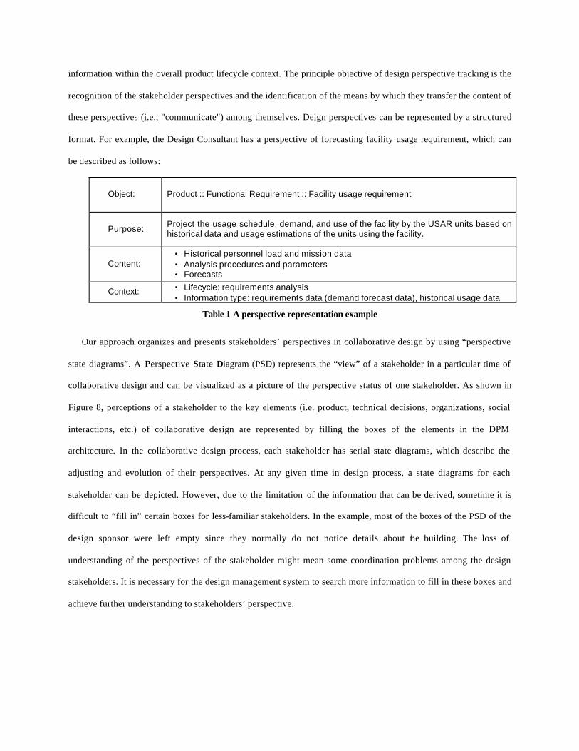
information within the overall product lifecycle context. The principle objective of design perspective tracking is the
recognition of the stakeholder perspectives and the identification of the means by which they transfer the content of
these perspectives (i.e., "communicate") among themselves. Deign perspectives can be represented by a structured
format. For example, the Design Consultant has a perspective of forecasting facility usage requirement, which can
be described as follows:
Object: Product :: Functional Requirement :: Facility usage requirement
Purpose: Project the usage schedule, demand, and use of the facility by the USAR units based on historical data and usage estimations of the units using the facility.
Content: • Historical personnel load and mission data • Analysis procedures and parameters • Forecasts
Context: • Lifecycle: requirements analysis • Information type: requirements data (demand forecast data), historical usage data
Table 1 A perspective representation example
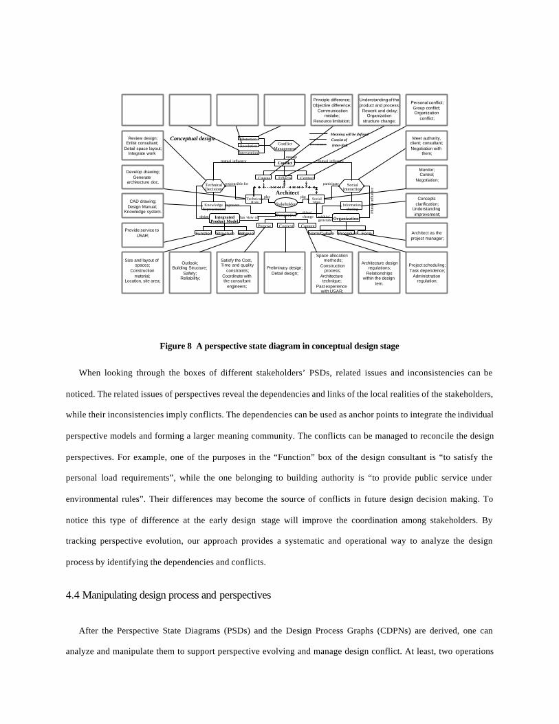
Our approach organizes and presents stakeholders’ perspectives in collaborative design by using “perspective
state diagrams”. A Perspective State Diagram (PSD) represents the “view” of a stakeholder in a particular time of
collaborative design and can be visualized as a picture of the perspective status of one stakeholder. As shown in
Figure 8, perceptions of a stakeholder to the key elements (i.e. product, technical decisions, organizations, social
interactions, etc.) of collaborative design are represented by filling the boxes of the elements in the DPM
architecture. In the collaborative design process, each stakeholder has serial state diagrams, which describe the
adjusting and evolution of their perspectives. At any given time in design process, a state diagrams for each
stakeholder can be depicted. However, due to the limitation of the information that can be derived, sometime it is
difficult to “fill in” certain boxes for less-familiar stakeholders. In the example, most of the boxes of the PSD of the
design sponsor were left empty since they normally do not notice details about the building. The loss of
understanding of the perspectives of the stakeholder might mean some coordination problems among the design
stakeholders. It is necessary for the design management system to search more information to fill in these boxes and
achieve further understanding to stakeholders’ perspective.
Detection
Resolution
Intervention
Causes Effects Context
Perspective
Purpose Context Content
Technical Role
Social Role
KnowledgeRepresentation
Information sharing
Function Structure Behavior Norm/Culture Procedure Form
Meaning will be definedConsist of Inter-link
mutual influence mutual influence
responsible for
Mut
ual i
nflu
ence
manage
participate
play play
design
represent
has view ofdrive/change within/
generate Organization IntegratedProduct Model
TechnicalDecisions
SocialInteraction
Stakeholder
Conflict
ConflictManagement
Outlook;Building Structure;
Safety;Reliability;
Satisfy the Cost, Time and quality
constraints;Coordinate with the consultant
engineers;
Size and layout of spaces;
Construction material;
Location, site area;
Preliminary design;Detail design;
Space allocation methods;
Construction process;
Architecture technique;
Past experience with USAR;
Architecture designregulations;
Relationships within the design
tem.
Project scheduling;Task dependence;
Administration regulation;
Architect as the project manager;
Principle difference;Objective difference;
Communicationmistake;
Resource limitation;
Understanding of the product and process;
Rework and delay;Organization
structure change;
Concepts clarification;
Understanding improvement;
Monitor;Control;
Negotiation;
Meet authority, client; consultant;Negotiation with
them;
Personal conflict;Group conflict;Organization
conflict;
Review design;Enlist consultant;
Detail space layout;Integrate work
Develop drawing;Generate
architecture doc.
Provide service to USAR;
CAD drawing;Design Manual;
Knowledge system.
Architect
Conceptual design
Figure 8 A perspective state diagram in conceptual design stage
When looking through the boxes of different stakeholders’ PSDs, related issues and inconsistencies can be
noticed. The related issues of perspectives reveal the dependencies and links of the local realities of the stakeholders,
while their inconsistencies imply conflicts. The dependencies can be used as anchor points to integrate the individual
perspective models and forming a larger meaning community. The conflicts can be managed to reconcile the design
perspectives. For example, one of the purposes in the “Function” box of the design consultant is “to satisfy the
personal load requirements”, while the one belonging to building authority is “to provide public service under
environmental rules”. Their differences may become the source of conflicts in future design decision making. To
notice this type of difference at the early design stage will improve the coordination among stakeholders. By
tracking perspective evolution, our approach provides a systematic and operational way to analyze the design
process by identifying the dependencies and conflicts.
4.4 Manipulating design process and perspectives
After the Perspective State Diagrams (PSDs) and the Design Process Graphs (CDPNs) are derived, one can
analyze and manipulate them to support perspective evolving and manage design conflict. At least, two operations

can be performed. The first is to examine the perspective state diagrams between/through adjacent points in time and
identify/reconcile conflicts in perspectives. The second is to iterate between step 2 and 3 to achieve the desired
effect (i.e., the desired conflict rate profile) by rearranging the design process to reconcile the contents of the
perspectives. While the design process is handled to control the conflict manner by applying these two approaches,
the efficiency of human design is improved by providing support to their negotiation.
As mentioned in the previous sections, at certain design stage, conflict can be detected by tracking and
comparing the “perspective states” of different stakeholders. If design perspectives are not tracked, due to the loss of
coordination, the chances of noticing difference and dependence are relatively low. Then, some design deficiencies
are not noticed until conflicts occur. For example, if tasks are executed according to the old schedule shown in
Figure 6 and design perspectives are not tracked, architect (i.e.S1) and design consultant (i.e. S2) might realize a
fatal conflict on the location selection after they discuss detail features of the building (after Task 9 in the schedule).
Since considerable jobs have already begun, that conflict will cause a lot of rework and waste time and money. As
shown in Figure 9, if perspectives are tracked and the PSDs of the design consultant and architect are depicted, an
inconsistency can be noticed by comparing the contents of the PSD elements for each stakeholder. Although there is
still no direct meeting between the stakeholders, a potential conflict on building location selection is identified much
earlier.
Gather client space usage information;
Space allocation requirement analysis;
Gather client space usage information;
Space allocation requirement analysis;
Technical Decision
Personnel schedule;Personnel loads;
Space usage;Building location;
Personnel schedule;Personnel loads;Space usage;
Building location;
Product
Space allocation;Space usage;
Building environment;Building regulation;
Building shape, material..
Space allocation;Space usage;
Building environment;Building regulation;
Building shape, material..
Technical Decision
Waiting for the layout from the design consultant
Waiting for the layout from the design consultant
Product
Report to owner;View clients as information
source;
Report to owner;View clients as information
source;
Organization
The role is not well defined yet The role is not well defined yet
Organization
Building location is chosen by users.
User prefer location A;
Building should not bevery near to road
intersection.Building location not
available
Design Consultant
Architect
Building space usage not available
Space usage;Personnel schedule;
Functionality;Looking;
Space usage;Personnel schedule;
Functionality;Looking;
Product
ClientOrganization
Matrix structure organization. Matrix structure organization.
location A is near road;location B is far from road;Only A and B and C are
feasible
Dependency noticed Inconsistency noticed
Figure 9 Comparing perspectives of three stakeholders

In this methodology, the formal algorithm of conflict detection is defined as:
ConflictManagement:: Detection(PSD_VariableA, PSD_VariableB, time) {
if (PSD_VariableA.type = PSD_Variable B. type) AND ( PSD_VariableA.value <> PSD_VariableB.value) Then (New Conflict) Else if (PSD_KnowledgeA RELATES PSD_VariableB) AND (PSD_KnowledgeA NOTsupport PSD_VariableB) Then (New Conflict) Else (No conflict detected) ….
}
Arranging the design process to a desired manner becomes an effective approach to coordinate the perspectives
of the stakeholders. The objective is to manipulate the PSDs as a way to converge them faster and therefore to
resolve conflict. The patterns of PSDs will largely depend on the interactions among the design tasks. For exa mple,
a new schedule can be proposed to let architect involve into the design campaign earlier so that he can identify the
key issues in layout design. After analyzing the task assignment matrix and task dependency matrix, a new task T8.1
is added to let the architect join the design and declare his concerns. Thus, the location decision conflict will be
prevented. A comparison of the old and new design process is showed in Figure 10. It is obvious the design
iterations are reduced while concurrency of process is increased.

DesignConsultant
Architect
Client
E8 E9T7 T8 E10T9
E13 T10
E14 T11 E16
E12 E15T10
E15
E11
T12
T8:Analyze personalloads
T9:Create layout T10:Review layout
T7:Create usage schedule
E8 E9T7 T8 E10T9
E13 T10
E14 T11 E16
E12 E15T10
E15
E11
T12
T8.1:Identify features related to layout
T9:Create layout T10:Review layout
DesignConsultant
Architect
Client
E9.1 T8.1 E9.2
Original Process
Revised Process
Figure 10 Rearrange design process to manage conflict
5 Information System to Support Collaborative Design
Several critical issues that arise in developing collaborative design support systems can be identified based on
the above discussion. First, it is necessary to have a system that can explicitly capture the perspectives of the
stakeholders and assist their interactions. For different stakeholders, the representation of their views of product and
organizations should capture individual attributes. Stakeholders’ goals, contexts and contents should be modeled in
the system in a structured way and be communicable to other stakeholders. Secondly, it is important for the system
to trace the merging of perspectives in the design process. Furthermore, by referencing to system knowledge base, it
might be able to evaluate the potential consequences of stakeholders’ decisions to collaborative design. Besides, it is
also critical to support design conflict management by facilitating both technical and social negotiations.

StakeholderStakeholder
Process dataProcess data Product dataProduct data Knowledge Repository
Knowledge Repository Organization dataOrganization data
Network Connection (www, TCP/IP, XML..)
Java/XML/HTML
SQL/AccessST/DPMS Infrastructure
Java application
Perspective Management
Conflict Management
Process Management
OrganizationManagement
Product Management
StakeholderStakeholder StakeholderStakeholder StakeholderStakeholder
Figure 11 STDPM system structure
The Socio-Technical Design Process Management (ST-DPM) system is a prototype implementation of the
methodology of manipulation of collaborative design process and conflict. It is quite different from the traditional
proposed information systems, which manage conflict by using exception handling approach (Klein, 1995) or by
eliminating data inconsistencies (Srirm et al., 1992). The objective of STDPMS is to provide a computerized
environment that supports the socio-technical coordination among stakeholders during conceptual design. The
system structure is shown in Figure 11. During design process, stakeholders’ perspectives are modeled in the system
and their various roles are depicted. Communication tools with network and server-client database access functions
enlighten the stakeholders located in different place to notify his and others’ perspectives. Several subsystems (e.g.
Conflict management, Process Management, Product Management, and Organization management) are provided to
support design interaction and manage design information. The system knowledge repository tracks the evolutions
of product and organization data. These changes will become feedback to the perspective models of the stakeholders
and influence the design process in the future.
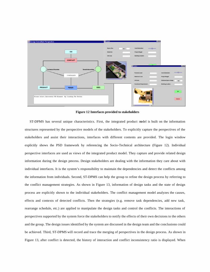
ST-DPMS has several unique characteristics. First, the integrated product model is built on the information
structures represented by the perspective models of the stakeholders. To explicitly capture the perspectives of the
stakeholders and assist their interactions, interfaces with different contents are provided. The login window
explicitly shows the PSD framework by referencing the Socio-Technical architecture (Figure 12). Individual
perspective interfaces are used as views of the integrated product model. They capture and provide related design
information during the design process. Design stakeholders are dealing with the information they care about with
individual interfaces. It is the system’s responsibility to maintain the dependencies and detect the conflicts among
the information from individuals. Second, ST-DPMS can help the group to refine the design process by referring to
the conflict management strategies. As shown in Figure 13, information of design tasks and the state of design
process are explicitly shown to the individual stakeholders. The conflict management model analyzes the causes,
effects and contexts of detected conflicts. Then the strategies (e.g. remove task dependencies, add new task,
rearrange schedule, etc.) are applied to manipulate the design tasks and control the conflicts. The interactions of
perspectives supported by the system force the stakeholders to notify the effects of their own decisions to the others
and the group. The design issues identified by the system are discussed in the design team and the conclusions could
be achieved. Third, ST-DPMS will record and trace the merging of perspectives in the design process. As shown in
Figure 13, after conflict is detected, the history of interaction and conflict inconsistency ratio is displayed. When
Figure 12 Interfaces provided to stakeholders

design issues and solutions are proposed during the design activities, the new concepts and ideas are captured by the
system. Consensus is treated as a common knowledge and stored in the system, which could be retrieved. That will
become very helpful to the future design. Fourth, when it is fully developed, the system can support the learning of
the rationale of the technical design decisions and conflict resolutions during the design process, like some proposed
systems such as iDCSS (Klein, 1995), and SHRAE-DRIM (Peña-Mora, 1995). The dynamic perspective mo dels are
supposed to capture the stakeholders’ local realities, their evolutions in design process can be also captured and
proposed to the team. That means the system is not only able to learn the design expertise and the design rationale,
but also can improve designers’ recognition and the organization structure, norm and culture.
Figure 13 Process view and conflict view in STDPM
6 Conclusions
This paper presents an original methodology for generic collaborative design process representation and conflicts
analysis with the belief that collaborative design process is not only a technical decision making process conducted
by a group of expertise, but a socio-technical interaction process among all of the stakeholders.
By using Petri Nets as convenient tools for topological and computational process illustration, a systematic
representation method of collaborative design process is developed. Several essential issues in collaborative design,
such as design state transformation, task dependencies, and task decomposition, can be clearly expressed by
applying the techniques of process modeling. This representation method provides the basics for collaborative

design process and conflict analysis. By investigating the relationship between perspective evolution and structure of
design process, conflicts can be effectively detected and analyzed. Managing design conflict becomes a coordination
infrastructure among design stakeholders to support the refinement of design process. By using conflict management
to identify the deficiencies of design process, this methodology realizes a feedback control mechanism to manipulate
collaborative design process, while the traditional approaches view it as an open loop system. The methodology also
provides a framework for information system development for collaborative design support. The aim of ST-DPMS
is to provide not only the design process management facility but also an integrated information support system for
collaborative design by capturing the perspective views of the stakeholders and handling the conflicts. Following
this direction, a series of design process management methodologies can be derived and implemented.
Our future research work will further refine the collaborative design process mo del by applying the advanced
analysis techniques of Petri Nets. Also, we hope to gain deep understanding of social interactions and their relations
to technical decisions occurred in more real-life collaborative design cases. Based on the further understanding of
the characteristics of design perspective interaction, the collaborative design process model and the design support
system can be improved significantly.
Acknowledgements Partially funding of this research was provided by the Construction Engineering Research Laboratories of the U. S.
Army, Corps of Engineers. We thank Mr. Eric Griffth and Dr. Mike Case for their continuous support. We are also
grateful for the help from Dr. F. Udwadia and Mr. W. Burkett, who have given us a lot of incentives to write this
paper.

References
1. Adler, P., & Mandelbaum, A.(1995). From Project to Process Management: An Empirically-Based Framework for Analyzing Product Development Time, Management Science, Vol. 41, No. 3, pp. 458-484.
2. Berger, P. & Luckman, T. (1966). The Social Construction of Reality A Treatise in the Sociology of Knowledge. Doubleday, New York, 1966.
3. Binmore, K. G. (1987). Why Game Theory “doesn’t work”?, Analyzing Conflict and Its Resolutions : Some Mathematical Contributions, P.G. Bennett.
4. Bras, B. A. & Mistree, F. (1991). Designing Design Process in Decision-Based Concurrent Engineering, SAE Transactions Journal of Materials &Manufacturing, Vol. 100, pp. 451-458.
5. David, R. & Alla, H. (1992). Petri Nets and Grafcet, Prentice Hall. 6. Eppinger D. S. (1997). Generalized Models of Design Iteration Using Signal Flow Graphs, Research in Engineering
Design. Vol. 9, pp. 112-123. 7. Jenson K. (1996). Coloured Petri Nets: Basic Concepts, Analysis Methods and Practical Use, Volume 1, Springer. 8. Jin Y., & Lu, S. C-Y. (1998). Toward a Better Understanding of Engineering Design Models, Proceedings of
Universal Design Theory Workshop, May 12-13. 9. Hauser, J. R. & Clausing, D.(1988). The House of Quality, Harvard Business Review, 63-73, May-June. 10. Kraus, S., Wilkenfeld, J., & Zlotkin, G.(1995). Multiagent Negotiation under Time Constraints, Artificial
Intelligence, Vol. 75, pp. 297-345. 11. Kannapan, S., & Taylor, D. (1994). The Interplay of Context, Process, and Conflict in Concurrent Engineering,
Journal of Concurrent Engineering Research and Applications, Vol. 2, pp. 183-196. 12. Klein, M. (1995). Conflict Management as a Part of an Integrated Exception Handing Approach, AIEDAM, Vol. 9,
pp. 259-267. 13. Krishnamurthy, K., & Law, H. K. (1997). A Data Management Model for Collaborative Design in a CAD
Environment, Engineering with Computers, Vol. 13, pp. 65-86, 1997. 14. Krishnan V. (1997) A Model-Based Framework to Overlap Product Development Activities, Management Science,
Vol.43, No. 4. 15. Lewis, K., & Mistree, F. (1997). Collaborative, Sequential and Isolated Decisions in Design. Proceedings of
DETC’97. 16. Lu, S. C-Y., Udwadia, F., Burkett, W., Cai, J. (1998) . Conflict Management in Collaborative Engineering Design
IMPACT Lab Technical Report. 17. Lu, S. C-Y, & Cai, J. (1999). Modeling Collaborative Design Process with a Socio-Technical Framework, Proceedings of 6th ISPE International Conference on Concurrent Engineering, Bath, United Kingdom, 1999.
18. Majumder D., Rangan, M. R., & Fulton, E. R. (1994). Information Management for Integrated Design Environments, Engineering with Computers, Vol. 11, pp. 227-245.
19. Paul, G. & Beitz, W. (1996). Engineering Design- A Systematic Approach, Second Edition, Springer, London. 20. Peña-Mora, F., Sriram, R.& Logcher, R.. (1995).Conflict Mitigation System for Collaborative Engineering,
AIEDAM, Vol.9, pp.101-124. 21. Petrie, C. J., et al. (1995). Using Pareto Optimality to Coordinate Distributed Agents, AIEDAM, Vol 9, pp269-281. 22. Sanvido, V. E., Norton, K. J., (1994). Integrated Design-Process Model, Journal of Management in Engineering,
Vol. 10, No. 5,pp. 55-62. 23. Simon, H. A., (1996). The Sciences of the artificial, Third Edition, MIT Press, Massachusetts. 24. Smith, P. R. & Eppinger, D. S. (1997). Identifying Controlling Features of Engineering Design Iteration,
Management Science, Vol. 43, No. 3. 25. Sowa,J.F. & Zachman, J. A. (1992). Extending and Formalizing the Framework for Information Systems
Architecture, IBM System Journal, Vol. 31,No 3. 26. Sriram, D., Ahmed, S. & Logcher, R. (1992). A Transaction Management Framework for Collaborative
Engineering, Engineering with Computers, Vol. 8, pp. 213-232. 27. Suh, N.P., (1990). The Principle of Design, Oxford Universtiy Press, Oxford. 28. Wall, J. A. & Calister, R. R. (1995). Conflict and Its Management, Journal of Management, Vol. 21, No.2, pp.
515-558. 29. Yoshikawa, H. (1981). General Design Theory and a CAD System, In Man-Machine Communication in
CAD/CAM, T. Sata, E. Warman. IFIP.