Embed Size (px)
Citation preview
1 Copyright © 2011 by ASME
A FUNCTION BASED APPROACH FOR PRODUCT INTEGRATION
Vishwa Kalyanasundaram Graduate Research Assistant
Department of Mechanical and Aerospace Engineering University at Buffalo – SUNY
Buffalo, NY 14260 [email protected]
Kemper Lewis Professor
Department of Mechanical and Aerospace Engineering University at Buffalo – SUNY
Buffalo, NY 14260 Corresponding Author: [email protected]
ABSTRACT Reconfigurable and multifunctional products are breeds of
products that cater to the increased diversification of customer
needs. Unlike single-state static products which can perform
only one primary function, these products cater to different
customer needs by performing more than one function with or
without changing their configuration. However, there is a lack
of systematic methods to support the conceptual task of
combining two existing single-state products into an integrated
product that provides multiple functions. In this paper, a
function based approach is proposed which provides more
rigorous support to assess the feasibility of integrating two
products. The function structures of the existing products are
combined to obtain the overall function structure of the
reconfigurable product. Function sharing, based on quantified
functional similarity, is proposed and applied to identify
functions that can be shared by the same component. The
information obtained from the function structure is then
mapped to the components of two existing products to analyze
their roles in the final reconfigurable product architecture. A
case study illustrates the proposed approach by analyzing the
integration of a power drill and a dust buster.
1.0 INTRODUCTION With the diversification of customer needs, the drawbacks of
single-state static systems are more evident. Their ability to
perform only one primary function has led to the emergence of
product types that perform multiple primary functions,
including reconfigurable systems and multifunction products..
Reconfigurable products have a broader functional repertoire
than the traditional single-state products [1]. They are designed
to perform a variety of functions, enhance performance or
execute the same function under different operating conditions
by changing its configuration. A reconfigurable aircraft shown
in Figure 1(a) can be converted into a car based on the
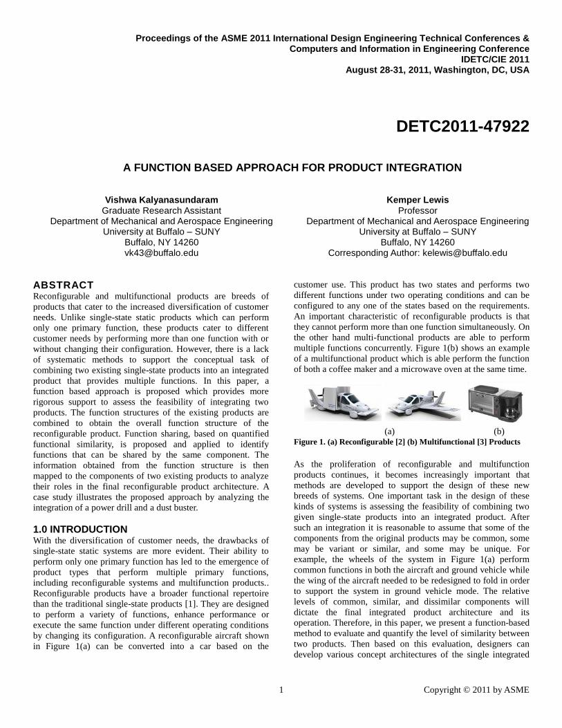
customer use. This product has two states and performs two
different functions under two operating conditions and can be
configured to any one of the states based on the requirements.
An important characteristic of reconfigurable products is that
they cannot perform more than one function simultaneously. On
the other hand multi-functional products are able to perform
multiple functions concurrently. Figure 1(b) shows an example
of a multifunctional product which is able perform the function
of both a coffee maker and a microwave oven at the same time.
As the proliferation of reconfigurable and multifunction
products continues, it becomes increasingly important that
methods are developed to support the design of these new
breeds of systems. One important task in the design of these
kinds of systems is assessing the feasibility of combining two
given single-state products into an integrated product. After
such an integration it is reasonable to assume that some of the
components from the original products may be common, some
may be variant or similar, and some may be unique. For
example, the wheels of the system in Figure 1(a) perform
common functions in both the aircraft and ground vehicle while
the wing of the aircraft needed to be redesigned to fold in order
to support the system in ground vehicle mode. The relative
levels of common, similar, and dissimilar components will
dictate the final integrated product architecture and its
operation. Therefore, in this paper, we present a function-based
method to evaluate and quantify the level of similarity between
two products. Then based on this evaluation, designers can
develop various concept architectures of the single integrated
(a) (b) Figure 1. (a) Reconfigurable [2] (b) Multifunctional [3] Products
Proceedings of the ASME 2011 International Design Engineering Technical Conferences & Computers and Information in Engineering Conference
IDETC/CIE 2011 August 28-31, 2011, Washington, DC, USA
DETC2011-47922
2 Copyright © 2011 by ASME
product. Thus far, a systematic approach to evaluate the
integration of two products has been missing from the design
literature.
In Section 2, related work on reconfigurable systems,
functional modeling, and function sharing is discussed along
with the fundamental background for the proposed approach. In
Section 3, we present the three phases of the approach and in
Section 4, the approach is applied to the integration of a power
drill and dust buster into a single product. Insights,
conclusions, limitations, and future work are discussed in
Section 5.
2 BACKGROUND With consumer preferences gaining the upper hand over mass
production, product proliferation is a new paradigm adopted
when designing a product [4]. With the large homogeneous
market shifting towards an increasingly heterogeneous market,
demand is being fragmented and the power is shifting to the
consumer [5]. This can be effectively addressed by providing
variety and customization in products through flexibility and
quick responsiveness.
2.1 Reconfigurable Products Reconfigurable products incorporate functionally different
products into a single product by allowing the customer to
configure the product to achieve the current desired
functionality. Reconfigurable manufacturing systems (RMS)
are predecessors of reconfigurable products which are
manufacturing systems that can be configured for different
operations for a given family of components [6]. In [7], four
primary aspects of changeable/reconfigurable systems are
presented: adaptability, flexibility, robustness and agility. In [8],
the use of flexibility is further delineated and quantified as an
engineering attribute in various fields. In [9], reconfigurable
systems are classified into multi-ability, evolution and
survivability based on their function, future capabilities, and
design and performance space requirements. These
classifications could be used to categorize possible outcomes of
the method presented in this paper.
Other research has looked at how the system can physically
reconfigure. An important part of the research in reconfigurable
systems that has emerged is the concept of transformation
principles [1, 10-11]. These principles were developed by
analyzing existing patents and reconfiguring systems, both
natural and manmade, to identify the primary methods that
systems transform from one form to another. The different
types of form transformations are called principles, which are
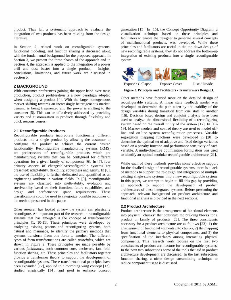
shown in Figure 2. These principles are made possible by
various facilitators, such common core, enclosure, fan, fold,
function sharing, etc. These principles and facilitators together
provide a transformer theory to support the development of
reconfigurable systems. These transformational principles have
been expanded [12], applied to a morphing wing concept [13],
studied empirically [14], and used to enhance concept
generation [15]. In [15], the Concept Opportunity Diagram, a
visualization technique based on these principles and
facilitators to enable the designer to generate several concepts
of multifunctional products, was developed. While these
principles and facilitators are useful in the top-down design of
new reconfigurable systems, they do not address the bottom-up
integration of existing products into a single reconfigurable
system.
Figure 2. Principles and Facilitators - Transformers Design [1]
Other methods have focused more on the detailed design of
reconfigurable systems. A linear state feedback model was
developed to determine the path taken by and stability of the
design variables during transition from one state to another
[16]. Decision based design and conjoint analysis have been
used to analyze the dimensional flexibility of a reconfiguring
system based on the overall utility of the system [17]. In [18-
19], Markov models and control theory are used to model off-
line and on-line system reconfiguration processes. Variable
segregation mapping functions were developed in [20] to
determine the optimal set of adaptive and fixed design variables
based on a penalty function and performance sensitivity of each
variable. A multi-objective optimization formulation was used
to identify an optimal modular reconfigurable architecture [21].
While each of these methods provides some effective support
for the detailed design of reconfigurable systems, there is a lack
of methods to support the re-design and integration of multiple
existing single-state systems into a new reconfigurable system.
In this paper, we attempt to begin to fill this gap by providing
an approach to support the development of product
architectures of these integrated systems. Before presenting the
approach, relevant background on product architecture and
functional analysis is provided in the next sections.
2.2 Product Architecture Product architecture is the arrangement of functional elements
into physical “chunks” that constitute the building blocks for a
product or family of products [22]. The three constituents
necessary for a product architecture are as follows [23]: 1) the
arrangement of functional elements into chunks, 2) the mapping
from functional elements to physical components, and 3) the
specification of the interfaces among interacting physical
components. This research work focuses on the first two
constituents of product architecture for reconfigurable systems.
In the next two subsections some of the tools that aid in product
architecture development are discussed. In the last subsection,
function sharing, a niche design streamlining technique to
reduce component usage is discussed.
Expose / Collapse Expose/ Cover Fuse / Divide
3 Copyright © 2011 by ASME
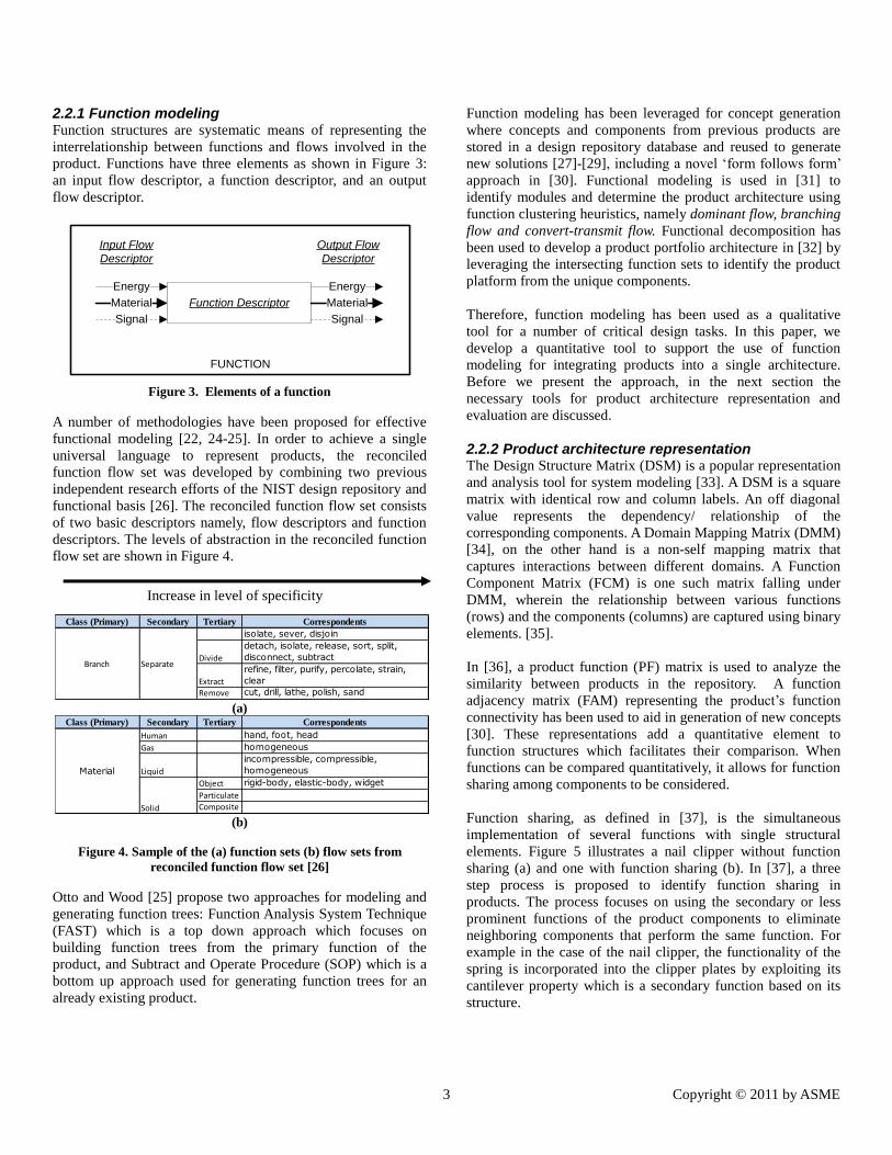
2.2.1 Function modeling Function structures are systematic means of representing the
interrelationship between functions and flows involved in the
product. Functions have three elements as shown in Figure 3:
an input flow descriptor, a function descriptor, and an output
flow descriptor.
Figure 3. Elements of a function
A number of methodologies have been proposed for effective
functional modeling [22, 24-25]. In order to achieve a single
universal language to represent products, the reconciled
function flow set was developed by combining two previous
independent research efforts of the NIST design repository and
functional basis [26]. The reconciled function flow set consists
of two basic descriptors namely, flow descriptors and function
descriptors. The levels of abstraction in the reconciled function
flow set are shown in Figure 4.
(a)
(b)
Figure 4. Sample of the (a) function sets (b) flow sets from
reconciled function flow set [26]
Otto and Wood [25] propose two approaches for modeling and
generating function trees: Function Analysis System Technique
(FAST) which is a top down approach which focuses on
building function trees from the primary function of the
product, and Subtract and Operate Procedure (SOP) which is a
bottom up approach used for generating function trees for an
already existing product.
Function modeling has been leveraged for concept generation
where concepts and components from previous products are
stored in a design repository database and reused to generate
new solutions [27]-[29], including a novel „form follows form‟
approach in [30]. Functional modeling is used in [31] to
identify modules and determine the product architecture using
function clustering heuristics, namely dominant flow, branching
flow and convert-transmit flow. Functional decomposition has
been used to develop a product portfolio architecture in [32] by
leveraging the intersecting function sets to identify the product
platform from the unique components.
Therefore, function modeling has been used as a qualitative
tool for a number of critical design tasks. In this paper, we
develop a quantitative tool to support the use of function
modeling for integrating products into a single architecture.
Before we present the approach, in the next section the
necessary tools for product architecture representation and
evaluation are discussed.
2.2.2 Product architecture representation The Design Structure Matrix (DSM) is a popular representation
and analysis tool for system modeling [33]. A DSM is a square
matrix with identical row and column labels. An off diagonal
value represents the dependency/ relationship of the
corresponding components. A Domain Mapping Matrix (DMM)
[34], on the other hand is a non-self mapping matrix that
captures interactions between different domains. A Function
Component Matrix (FCM) is one such matrix falling under
DMM, wherein the relationship between various functions
(rows) and the components (columns) are captured using binary
elements. [35].
In [36], a product function (PF) matrix is used to analyze the
similarity between products in the repository. A function
adjacency matrix (FAM) representing the product‟s function
connectivity has been used to aid in generation of new concepts
[30]. These representations add a quantitative element to
function structures which facilitates their comparison. When
functions can be compared quantitatively, it allows for function
sharing among components to be considered.
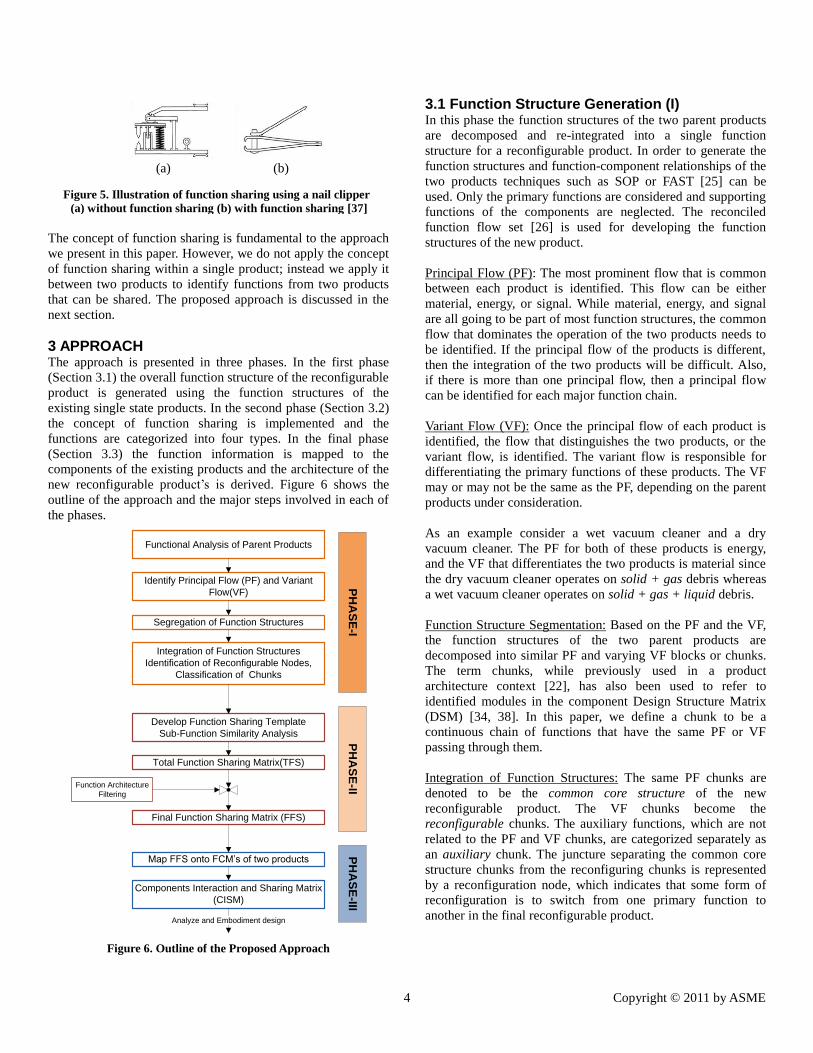
Function sharing, as defined in [37], is the simultaneous
implementation of several functions with single structural
elements. Figure 5 illustrates a nail clipper without function
sharing (a) and one with function sharing (b). In [37], a three
step process is proposed to identify function sharing in
products. The process focuses on using the secondary or less
prominent functions of the product components to eliminate
neighboring components that perform the same function. For
example in the case of the nail clipper, the functionality of the
spring is incorporated into the clipper plates by exploiting its
cantilever property which is a secondary function based on its
structure.
Function Descriptor
Energy
Material
Signal
Energy
Material
Signal
Input Flow
Descriptor
FUNCTION
Output Flow
Descriptor
Class (Primary) Secondary Tertiary Correspondents
isolate, sever, disjoin
Divide
detach, isolate, release, sort, split,
disconnect, subtract
Extract
refine, filter, purify, percolate, strain,
clear
Remove cut, drill, lathe, polish, sand
Branch Separate
Class (Primary) Secondary Tertiary Correspondents
Human hand, foot, head
Gas homogeneous
Liquid
incompressible, compressible,
homogeneous
Object rigid-body, elastic-body, widget
Particulate
CompositeSolid
Material
Increase in level of specificity
4 Copyright © 2011 by ASME
The concept of function sharing is fundamental to the approach
we present in this paper. However, we do not apply the concept
of function sharing within a single product; instead we apply it
between two products to identify functions from two products
that can be shared. The proposed approach is discussed in the
next section.
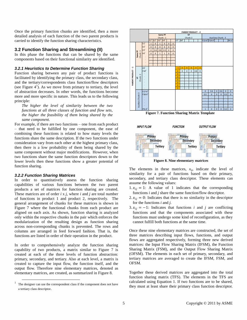
3 APPROACH The approach is presented in three phases. In the first phase
(Section 3.1) the overall function structure of the reconfigurable
product is generated using the function structures of the
existing single state products. In the second phase (Section 3.2)
the concept of function sharing is implemented and the
functions are categorized into four types. In the final phase
(Section 3.3) the function information is mapped to the
components of the existing products and the architecture of the
new reconfigurable product‟s is derived. Figure 6 shows the
outline of the approach and the major steps involved in each of
the phases.
Figure 6. Outline of the Proposed Approach
3.1 Function Structure Generation (I) In this phase the function structures of the two parent products
are decomposed and re-integrated into a single function
structure for a reconfigurable product. In order to generate the
function structures and function-component relationships of the
two products techniques such as SOP or FAST [25] can be
used. Only the primary functions are considered and supporting
functions of the components are neglected. The reconciled
function flow set [26] is used for developing the function
structures of the new product.
Principal Flow (PF): The most prominent flow that is common
between each product is identified. This flow can be either
material, energy, or signal. While material, energy, and signal
are all going to be part of most function structures, the common
flow that dominates the operation of the two products needs to
be identified. If the principal flow of the products is different,
then the integration of the two products will be difficult. Also,
if there is more than one principal flow, then a principal flow
can be identified for each major function chain.
Variant Flow (VF): Once the principal flow of each product is
identified, the flow that distinguishes the two products, or the
variant flow, is identified. The variant flow is responsible for
differentiating the primary functions of these products. The VF
may or may not be the same as the PF, depending on the parent
products under consideration.
As an example consider a wet vacuum cleaner and a dry
vacuum cleaner. The PF for both of these products is energy,
and the VF that differentiates the two products is material since
the dry vacuum cleaner operates on solid + gas debris whereas
a wet vacuum cleaner operates on solid + gas + liquid debris.
Function Structure Segmentation: Based on the PF and the VF,
the function structures of the two parent products are
decomposed into similar PF and varying VF blocks or chunks.
The term chunks, while previously used in a product
architecture context [22], has also been used to refer to
identified modules in the component Design Structure Matrix
(DSM) [34, 38]. In this paper, we define a chunk to be a
continuous chain of functions that have the same PF or VF
passing through them.
Integration of Function Structures: The same PF chunks are
denoted to be the common core structure of the new
reconfigurable product. The VF chunks become the
reconfigurable chunks. The auxiliary functions, which are not
related to the PF and VF chunks, are categorized separately as
an auxiliary chunk. The juncture separating the common core
structure chunks from the reconfiguring chunks is represented
by a reconfiguration node, which indicates that some form of
reconfiguration is to switch from one primary function to
another in the final reconfigurable product.
Functional Analysis of Parent Products
Identify Principal Flow (PF) and Variant
Flow(VF)
Integration of Function Structures
Identification of Reconfigurable Nodes,
Classification of Chunks
Develop Function Sharing Template
Sub-Function Similarity Analysis
Total Function Sharing Matrix(TFS)
Final Function Sharing Matrix (FFS)
Map FFS onto FCM’s of two products
Components Interaction and Sharing Matrix
(CISM)
Function Architecture
Filtering
PH
AS
E-I
PH
AS
E-II
PH
AS
E-III
Analyze and Embodiment design
Segregation of Function Structures
(b) (a)
Figure 5. Illustration of function sharing using a nail clipper
(a) without function sharing (b) with function sharing [37]
5 Copyright © 2011 by ASME
Once the primary function chunks are identified, then a more
detailed analysis of each function of the two parent products is
carried to identify the function sharing characteristics.
3.2 Function Sharing and Streamlining (II) In this phase the functions that can be shared by the same
components based on their functional similarity are identified.
3.2.1 Heuristics to Determine Function Sharing Function sharing between any pair of product functions is
facilitated by identifying the primary class, the secondary class,
and the tertiary/correspondents class function/flow descriptors
(see Figure 41). As we move from primary to tertiary, the level
of abstraction decreases. In other words, the functions become
more and more specific in nature. This leads us to the following
principle:
The higher the level of similarity between the two
functions at all three classes of function and flow sets,
the higher the feasibility of them being shared by the
same component.
For example, if there are two functions – one from each product
– that need to be fulfilled by one component, the ease of
combining these functions is related to how many levels the
functions share the same description. If the two functions under
consideration vary from each other at the highest primary class,
then there is a low probability of them being shared by the
same component without major modifications. However, when
two functions share the same function descriptors down to the
lower levels then these functions show a greater potential of
function sharing.
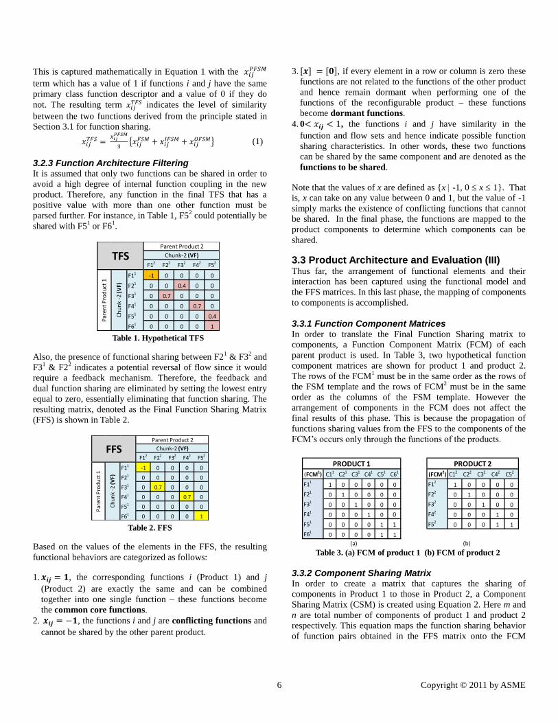
3.2.2 Function Sharing Matrices In order to quantitatively assess the function sharing
capabilities of various functions between the two parent
products a set of matrices for function sharing are created.
These matrices are of order i x j, where i and j are total number
of functions in product 1 and product 2, respectively. The
general arrangement of chunks for these matrices is shown in
Figure 7 where the functional chunks from each product are
aligned on each axis. As shown, function sharing is analyzed
only within the respective chunks in the pair which enforces the
modularization of the resulting design as function sharing
across non-corresponding chunks is prevented. The rows and
columns are arranged in feed forward fashion. That is, the
functions are listed in order of their operation in the product.
In order to comprehensively analyze the function sharing
capability of two products, a matrix similar to Figure 7 is
created at each of the three levels of function abstraction:
primary, secondary, and tertiary. Also at each level, a matrix is
created to capture the input flow, the function itself, and the
output flow. Therefore nine elementary matrices, denoted as
elementary matrices, are created, as summarized in Figure 8.
1 The designer can use the correspondent class if the component does not have
a tertiary class descriptor.
Figure 8. Nine elementary matrices
The elements in these matrices, xij, indicate the level of
similarity for a pair of functions based on their primary,
secondary, and tertiary class descriptor. These elements can
assume the following values:
1. : A value of 1 indicates that the corresponding
functions i and j share the same function/flow descriptor.
2. : Indicates that there is no similarity in the descriptor
for the functions i and j.
3. : Indicates that functions i and j are conflicting
functions and that the components associated with these
functions must undergo some kind of reconfiguration, as they
cannot fulfill both functions at the same time.
Once these nine elementary matrices are constructed, the set of
three matrices describing input flows, functions, and output
flows are aggregated respectively, forming three new derived
matrices: the Input Flow Sharing Matrix (IFSM), the Function
Sharing Matrix (FSM), and the Output Flow Sharing Matrix
(OFSM). The elements in each set of primary, secondary, and
tertiary matrices are averaged to create the IFSM, FSM, and
OFSM.
Together these derived matrices are aggregated into the total
function sharing matrix (TFS). The elements in the TFS are
calculated using Equation 1. If two functions are to be shared,
they must at least share their primary class function descriptor.
F12 F22 F32 F42. . F72 F82
. . . . F13-A2 F14-A2. . . FN-A2
F11 1 0 1 0 0 0
F21 0 0 0 0 0 0
F31 0 0.4 0.8 0.3 0 0
F41 0 0 1 1 0 0
. . . . . . .
. . . . . . .
. . . . . . .
. . . . . . .
F91 -1 0 0 0 0 0
F101 0 0 0 0 0.8 0
. 0 . . . . .
. 0 . . . . .
. 0 . . . . .
. 0 . . . . .
. 0 . . . . .
. 0 . . . . .
F17-A1 0 0.4 0 0.6 0 0
F18-A1 0.5 0 0 0 0.3 0
. . . . . . .
. . . . . . .
. . . . . . .
. . . . . . .
FN-A1 1 0 0 0 0.2 0
PARENT PRODUCT - 2
PA
REN
T P
RO
DU
CT
- 1
VF
Chunk-2
Au
xilia
ry C
hu
nk-
3
Auxiliary Chunk - 3
Same PF
Chunk - 1
Sam
e P
F
Ch
un
k -1
VF
Ch
un
k -2
Figure 7. Function Sharing Matrix Template
6 Copyright © 2011 by ASME
This is captured mathematically in Equation 1 with the
term which has a value of 1 if functions i and j have the same
primary class function descriptor and a value of 0 if they do
not. The resulting term indicates the level of similarity
between the two functions derived from the principle stated in
Section 3.1 for function sharing.
(1)
3.2.3 Function Architecture Filtering It is assumed that only two functions can be shared in order to
avoid a high degree of internal function coupling in the new
product. Therefore, any function in the final TFS that has a
positive value with more than one other function must be
parsed further. For instance, in Table 1, F52 could potentially be
shared with F51 or F6
1.
Table 1. Hypothetical TFS
Also, the presence of functional sharing between F21 & F3
2 and
F31 & F2
2 indicates a potential reversal of flow since it would
require a feedback mechanism. Therefore, the feedback and
dual function sharing are eliminated by setting the lowest entry
equal to zero, essentially eliminating that function sharing. The
resulting matrix, denoted as the Final Function Sharing Matrix
(FFS) is shown in Table 2.
Table 2. FFS
Based on the values of the elements in the FFS, the resulting
functional behaviors are categorized as follows:
1. , the corresponding functions i (Product 1) and j
(Product 2) are exactly the same and can be combined
together into one single function – these functions become
the common core functions. 2. , the functions i and j are conflicting functions and
cannot be shared by the other parent product.
3. , if every element in a row or column is zero these
functions are not related to the functions of the other product
and hence remain dormant when performing one of the
functions of the reconfigurable product – these functions
become dormant functions.
4. 0 , the functions i and j have similarity in the
function and flow sets and hence indicate possible function
sharing characteristics. In other words, these two functions
can be shared by the same component and are denoted as the
functions to be shared.
Note that the values of x are defined as {x -1, 0 x 1}. That
is, x can take on any value between 0 and 1, but the value of -1
simply marks the existence of conflicting functions that cannot
be shared. In the final phase, the functions are mapped to the
product components to determine which components can be
shared.
3.3 Product Architecture and Evaluation (III) Thus far, the arrangement of functional elements and their
interaction has been captured using the functional model and
the FFS matrices. In this last phase, the mapping of components
to components is accomplished.
3.3.1 Function Component Matrices In order to translate the Final Function Sharing matrix to
components, a Function Component Matrix (FCM) of each
parent product is used. In Table 3, two hypothetical function
component matrices are shown for product 1 and product 2.
The rows of the FCM1 must be in the same order as the rows of
the FSM template and the rows of FCM2 must be in the same
order as the columns of the FSM template. However the
arrangement of components in the FCM does not affect the
final results of this phase. This is because the propagation of
functions sharing values from the FFS to the components of the
FCM‟s occurs only through the functions of the products.
Table 3. (a) FCM of product 1 (b) FCM of product 2
3.3.2 Component Sharing Matrix In order to create a matrix that captures the sharing of
components in Product 1 to those in Product 2, a Component
Sharing Matrix (CSM) is created using Equation 2. Here m and
n are total number of components of product 1 and product 2
respectively. This equation maps the function sharing behavior
of function pairs obtained in the FFS matrix onto the FCM
F12 F22 F32 F42 F52
F11 -1 0 0 0 0
F21 0 0 0.4 0 0
F31 0 0.7 0 0 0
F41 0 0 0 0.7 0
F51 0 0 0 0 0.4
F61 0 0 0 0 1
TFSParent Product 2
Chunk-2 (VF)
Par
ent
Pro
du
ct 1
Ch
un
k -2
(VF)
F12 F22 F32 F42 F52
F11 -1 0 0 0 0
F21 0 0 0 0 0
F31 0 0.7 0 0 0
F41 0 0 0 0.7 0
F51 0 0 0 0 0
F61 0 0 0 0 1
FFSParent Product 2
Chunk-2 (VF)
Par
ent
Pro
du
ct 1
Ch
un
k -2
(VF) (FCM1) C11 C21 C31 C41 C51 C61 (FCM2) C12 C22 C32 C42 C52
F111 0 0 0 0 0 F12
1 0 0 0 0
F210 1 0 0 0 0 F22
0 1 0 0 0
F310 0 1 0 0 0 F32
0 0 1 0 0
F410 0 0 1 0 0 F42
0 0 0 1 0
F510 0 0 0 1 1 F52
0 0 0 1 1
F610 0 0 0 1 1
(a) (b)
PRODUCT 1 PRODUCT 2
7 Copyright © 2011 by ASME
matrices of product 1 and product 2, located to the left and right
side of FFS respectively
(2)
Note that the operator {*} in Equation 2 does not represent the
usual matrix multiplication. This is because if the standard
multiplication rules are used, the function sharing values would
be added which does not make conceptual sense. Therefore, the
{*} operator projects the FFS values onto FCM1 and FCM
2
while at the same time preserving the unit normalization. In
effect, it is an enhanced dot product of three matrices. The {*}
is two step process; the mechanics involved in this equation and
its multiplicative procedure are explained using simple
matrices.
Consider Table 4 which shows the operation {*} for the first
two matrices in Equation 2. The multiplication for the matrices
is modified in the following manner,
1. When row 1 (C11) [1,0,0,0,0,0] of (FCM
1)
T is multiplied with
column 1 (F12) [-1,0,0,0,0,0]
T of FFS, each element is
multiplied with the corresponding element and is stored in a
set Sxy as {1*-1,0*0,0*0,0*0,0*0} as denoted in Equation 3.
(3)
This is simply the projection of the function relationship in
the FFS onto the components of Product 1where M1
represents the elements of Matrix 1 and M2 the elements of
Matrix 2.
Table 4. (a) [FCM1]T of product 1 (b) FFS
2. Once the projection is obtained, we must identify the
dominating term of the set , denoted as aij. Equation 4
represents how this is carried out.
(4)
The first condition, an empty set Sxy, identifies dormant
components that bear no relation with components of the other
product. The second condition identifies the conflicting
components by detecting the presence of -1 in the set Sxy. The
third condition ensures that only the lowest possible number in
Sxy is taken into consideration when there are multiple positive
numbers present. The lowest number conservatively reflects the
minimum similarity exhibited by that component pair
indicating the maximum redesign effort required.
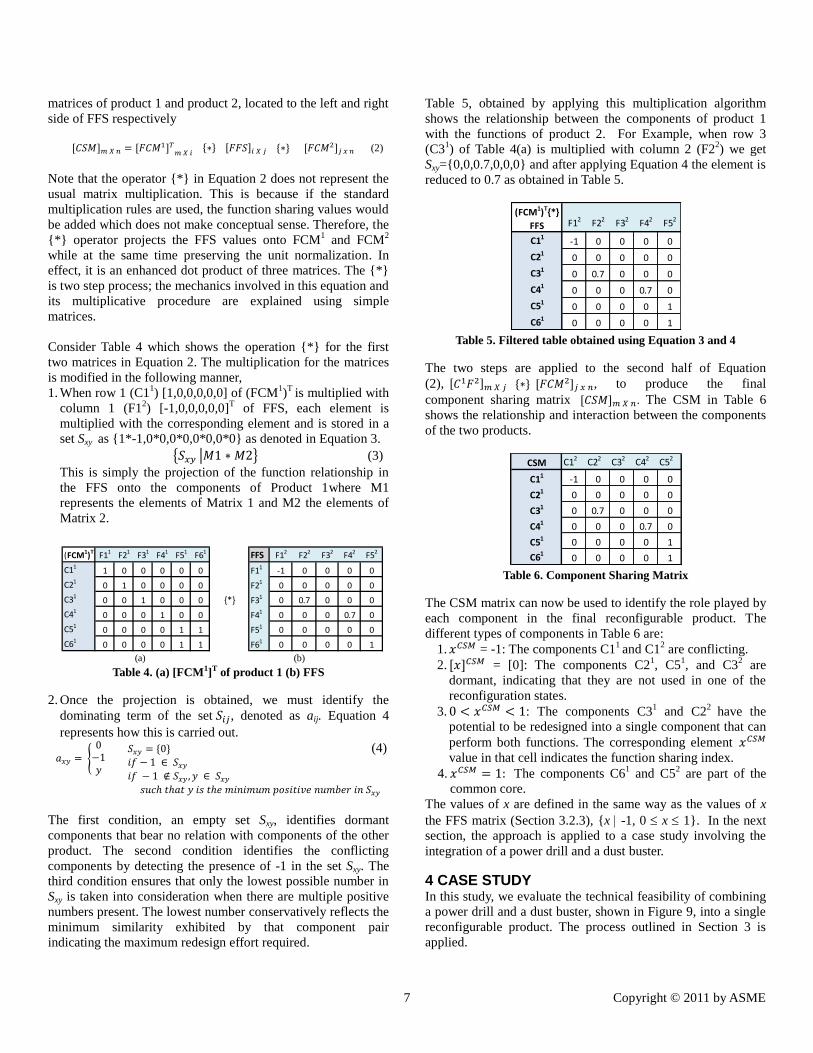
Table 5, obtained by applying this multiplication algorithm
shows the relationship between the components of product 1
with the functions of product 2. For Example, when row 3
(C31) of Table 4(a) is multiplied with column 2 (F2
2) we get
Sxy={0,0,0.7,0,0,0} and after applying Equation 4 the element is
reduced to 0.7 as obtained in Table 5.
Table 5. Filtered table obtained using Equation 3 and 4
The two steps are applied to the second half of Equation
(2), , to produce the final
component sharing matrix . The CSM in Table 6
shows the relationship and interaction between the components
of the two products.
Table 6. Component Sharing Matrix
The CSM matrix can now be used to identify the role played by
each component in the final reconfigurable product. The
different types of components in Table 6 are:
1. = -1: The components C11 and C1
2 are conflicting.
2. = [0]: The components C21, C5
1, and C3
2 are
dormant, indicating that they are not used in one of the
reconfiguration states.
3. : The components C31 and C2
2 have the
potential to be redesigned into a single component that can
perform both functions. The corresponding element
value in that cell indicates the function sharing index. 4. The components C6
1 and C5
2 are part of the
common core.
The values of x are defined in the same way as the values of x
the FFS matrix (Section 3.2.3), {x -1, 0 x 1}. In the next
section, the approach is applied to a case study involving the
integration of a power drill and a dust buster.
4 CASE STUDY In this study, we evaluate the technical feasibility of combining
a power drill and a dust buster, shown in Figure 9, into a single
reconfigurable product. The process outlined in Section 3 is
applied.
(FCM1)T F11 F21 F31 F41 F51 F61 FFS F12 F22 F32 F42 F52
C111 0 0 0 0 0 F11 -1 0 0 0 0
C210 1 0 0 0 0 F21 0 0 0 0 0
C310 0 1 0 0 0 {*} F31 0 0.7 0 0 0
C410 0 0 1 0 0 F41 0 0 0 0.7 0
C510 0 0 0 1 1 F51 0 0 0 0 0
C610 0 0 0 1 1 F61 0 0 0 0 1
(a) (b)
(FCM1)T{*}
FFS F12 F22 F32 F42 F52
C11-1 0 0 0 0
C210 0 0 0 0
C310 0.7 0 0 0
C410 0 0 0.7 0
C510 0 0 0 1
C610 0 0 0 1
CSM C12 C22 C32 C42 C52
C11 -1 0 0 0 0
C21 0 0 0 0 0
C31 0 0.7 0 0 0
C41 0 0 0 0.7 0
C51 0 0 0 0 1
C610 0 0 0 1
8 Copyright © 2011 by ASME
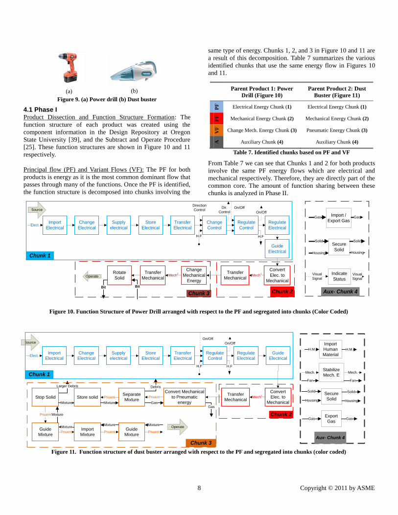
4.1 Phase I Product Dissection and Function Structure Formation: The
function structure of each product was created using the
component information in the Design Repository at Oregon
State University [39], and the Subtract and Operate Procedure
[25]. These function structures are shown in Figure 10 and 11
respectively.
Principal flow (PF) and Variant Flows (VF): The PF for both
products is energy as it is the most common dominant flow that
passes through many of the functions. Once the PF is identified,
the function structure is decomposed into chunks involving the
same type of energy. Chunks 1, 2, and 3 in Figure 10 and 11 are
a result of this decomposition. Table 7 summarizes the various
identified chunks that use the same energy flow in Figures 10
and 11.
Parent Product 1: Power
Drill (Figure 10)
Parent Product 2: Dust
Buster (Figure 11)
PF
Electrical Energy Chunk (1) Electrical Energy Chunk (1)
PF
Mechanical Energy Chunk (2) Mechanical Energy Chunk (2)
VF
Change Mech. Energy Chunk (3) Pneumatic Energy Chunk (3)
A
Auxiliary Chunk (4) Auxiliary Chunk (4)
Table 7. Identified chunks based on PF and VF
From Table 7 we can see that Chunks 1 and 2 for both products
involve the same PF energy flows which are electrical and
mechanical respectively. Therefore, they are directly part of the
common core. The amount of function sharing between these
chunks is analyzed in Phase II.
Figure 10. Function Structure of Power Drill arranged with respect to the PF and segregated into chunks (Color Coded)
Figure 11. Function structure of dust buster arranged with respect to the PF and segregated into chunks (color coded)
(a) (b)
Figure 9. (a) Power drill (b) Dust buster
Import
Electrical
Operate
Supply
electrical
Change
Electrical
Guide
Electrical
Regulate
Electrical
Regulate
Control
Change
Control
Transfer
Electrical
Store
Electrical
Convert
Elec. to
Mechanical
Transfer
Mechanical
Change
Mechanical
Energy
Transfer
Mechanical
Rotate
Solid
Elect.
Mech1
Mech2
BitBit
On/Off
On/Off
H.F H.F
Dir.
Control
Direction
Control
Visual
Signal
Import /
Export Gas
Secure
Solid
Indicate
Status
Solid Solid
Housing Housing
Visual
Signal
Gas Gas
Aux- Chunk 4
Chunk 1
Chunk 2Chunk 3
Source
Chunk 3
Operate
Source
Larger Debris Debris
GasGas
Import
Electrical
Supply
electrical
Change
Electrical
Guide
Electrical
Regulate
Electrical
Regulate
Control
Transfer
Electrical
Store
Electrical
Convert
Elec. to
Mechanical
Transfer
Mechanical
Elect.
Mech1
On/Off
On/Off
H.F H.F
Chunk 1
Chunk 2
Convert Mechanical
to Pneumatic
energy
Separate
MixtureStore solidStop Solid
Guide
Mixture
Import
Mixture
Guide
Mixture
Pnuem
Mixture
Pnuem
Pnuem
Mixture
Mixture
Mixture
Pnuem
Mixture
Pnuem
Mixture
Pnuem
Import
Human
Material
Stabilize
Mech. E
Secure
Solid
H.M.
Mech.
Fan Fan
Solid
Housing
Aux- Chunk 4
H.M.
Mech.
Solid
Housing
Export
GasGas Gas
9 Copyright © 2011 by ASME
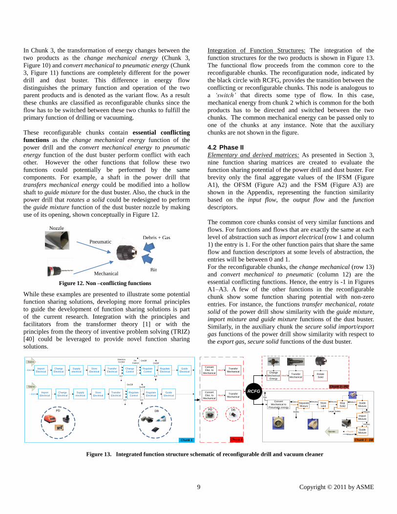
In Chunk 3, the transformation of energy changes between the
two products as the change mechanical energy (Chunk 3,
Figure 10) and convert mechanical to pneumatic energy (Chunk
3, Figure 11) functions are completely different for the power
drill and dust buster. This difference in energy flow
distinguishes the primary function and operation of the two
parent products and is denoted as the variant flow. As a result
these chunks are classified as reconfigurable chunks since the
flow has to be switched between these two chunks to fulfill the
primary function of drilling or vacuuming.
These reconfigurable chunks contain essential conflicting
functions as the change mechanical energy function of the
power drill and the convert mechanical energy to pneumatic
energy function of the dust buster perform conflict with each
other. However the other functions that follow these two
functions could potentially be performed by the same
components. For example, a shaft in the power drill that
transfers mechanical energy could be modified into a hollow
shaft to guide mixture for the dust buster. Also, the chuck in the
power drill that rotates a solid could be redesigned to perform
the guide mixture function of the dust buster nozzle by making
use of its opening, shown conceptually in Figure 12.
While these examples are presented to illustrate some potential
function sharing solutions, developing more formal principles
to guide the development of function sharing solutions is part
of the current research. Integration with the principles and
facilitators from the transformer theory [1] or with the
principles from the theory of inventive problem solving (TRIZ)
[40] could be leveraged to provide novel function sharing
solutions.
Integration of Function Structures: The integration of the
function structures for the two products is shown in Figure 13.
The functional flow proceeds from the common core to the
reconfigurable chunks. The reconfiguration node, indicated by
the black circle with RCFG, provides the transition between the
conflicting or reconfigurable chunks. This node is analogous to
a ‘switch’ that directs some type of flow. In this case,
mechanical energy from chunk 2 which is common for the both
products has to be directed and switched between the two
chunks. The common mechanical energy can be passed only to
one of the chunks at any instance. Note that the auxiliary
chunks are not shown in the figure.
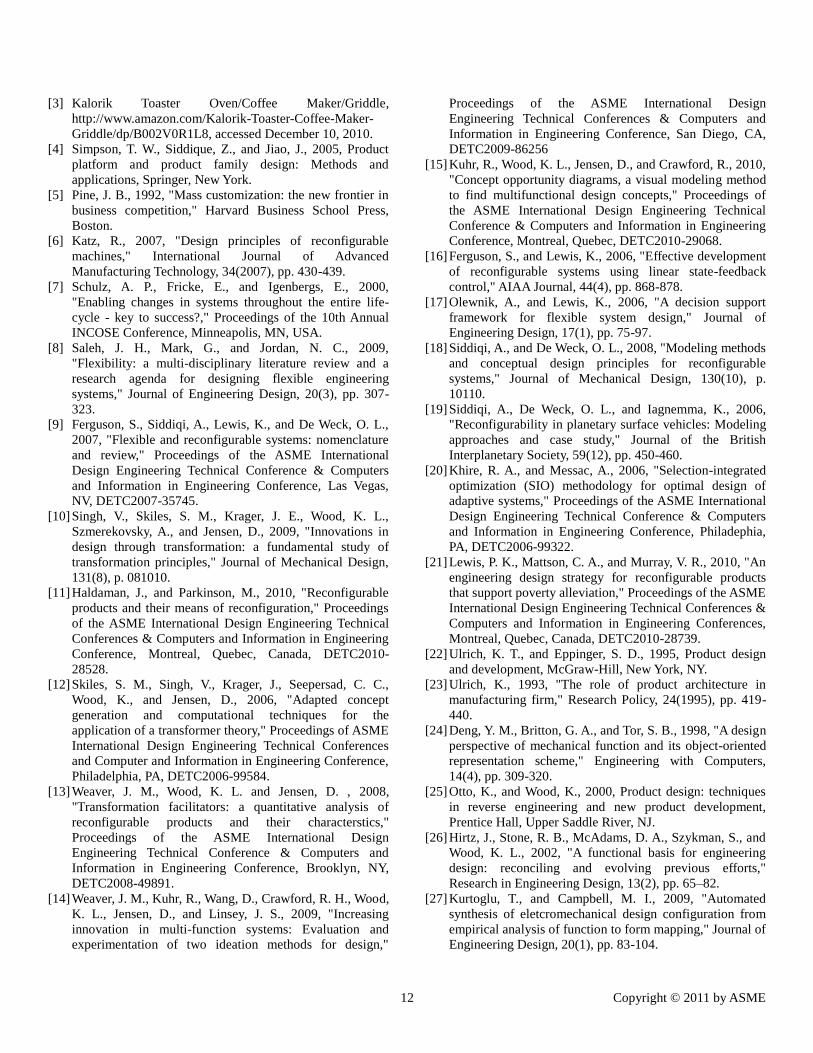
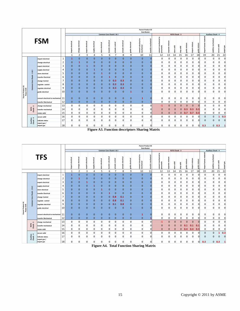
4.2 Phase II Elementary and derived matrices: As presented in Section 3,
nine function sharing matrices are created to evaluate the
function sharing potential of the power drill and dust buster. For
brevity only the final aggregate values of the IFSM (Figure
A1), the OFSM (Figure A2) and the FSM (Figure A3) are
shown in the Appendix, representing the function similarity
based on the input flow, the output flow and the function
descriptors.
The common core chunks consist of very similar functions and
flows. For functions and flows that are exactly the same at each
level of abstraction such as import electrical (row 1 and column
1) the entry is 1. For the other function pairs that share the same
flow and function descriptors at some levels of abstraction, the
entries will be between 0 and 1.
For the reconfigurable chunks, the change mechanical (row 13)
and convert mechanical to pneumatic (column 12) are the
essential conflicting functions. Hence, the entry is -1 in Figures
A1–A3. A few of the other functions in the reconfigurable
chunk show some function sharing potential with non-zero
entries. For instance, the functions transfer mechanical, rotate
solid of the power drill show similarity with the guide mixture,
import mixture and guide mixture functions of the dust buster.
Similarly, in the auxiliary chunk the secure solid import/export
gas functions of the power drill show similarity with respect to
the export gas, secure solid functions of the dust buster.
Figure 13. Integrated function structure schematic of reconfigurable drill and vacuum cleaner
Import
Electrical
Supply
electrical
Change
Electrical
Guide
Electrical
Regulate
Electrical
Regulate
Control
Change
Control
Transfer
Electrical
Store
Electrical
Convert
Elec. to
Mechanical
Transfer
Mechanical Change
Mechanical
Energy
Transfer
Mechanical
Rotate
Solid
Elect. Mech1
Mech2
On/Off
On/Off
H.F H.F
Dir.
Control
Direction
Control
Chunk 1 Chunk 2
Chunk 3 - PD
Source
Source
Import
Electrical
Supply
electrical
Change
Electrical
Guide
Electrical
Regulate
Electrical
Regulate
Control
Transfer
Electrical
Store
ElectricalElect.
On/Off
On/Off
H.F H.F
PD DB
Convert
Elec. to
Mechanical
Transfer
MechanicalMech
1
PD DB
Convert
Mechanical to
Pneumatic energy
Separate
Mixture
Store
solid
Guide
Mixture
Stop
Solid
Guide
Mixture
Import
Mixture
Chunk 3 - DB
Pnuem
Pnuem
Mixture
Mixture
Mixture
Larger Debris
MixtureMixture
Debris
Gas
Gas
Operate
Mixture
RCFG
Nozzle
Pneumatic Debris + Gas
Mechanical Bit
Figure 12. Non –conflicting functions
10 Copyright © 2011 by ASME
TFS and FFS: Figure A4 shows the total function sharing (TFS)
matrix which is the aggregation of the IFSM, OFSM, and FSM
matrices using Equation 1. This matrix captures the function
and flow similarity that exists between the functions of the two
products. Since there are multiple functions of both products
that could be shared, the most promising pairs of functions are
kept in the Final Function Sharing matrix as shown in Figure
A5. This is done to minimize the amount of functional coupling
in the final product. For example, the TFS recommends that the
functions change control, regulate control, regulate electrical
(rows 7-9) of the power drill are coupled with the functions
actuate control and actuate electrical (columns 7-8) of the dust
buster. While possible, redesigning the necessary components
to provide this level of function sharing may lead to very
complex and unpredictable behavior. Therefore, the TFS is
constructed to keep the sharing of functions as modularized as
possible.
4.3 Phase III The FCM
1 of the power drill is shown in Figure A6 and the
FCM2 of the dust buster is shown in Figure A7. The component
sharing matrix (CSM) is generated by using Equations 2-4
along with the FCM1, FCM
2, and FFS. The final CSM is shown
in Figure A8.
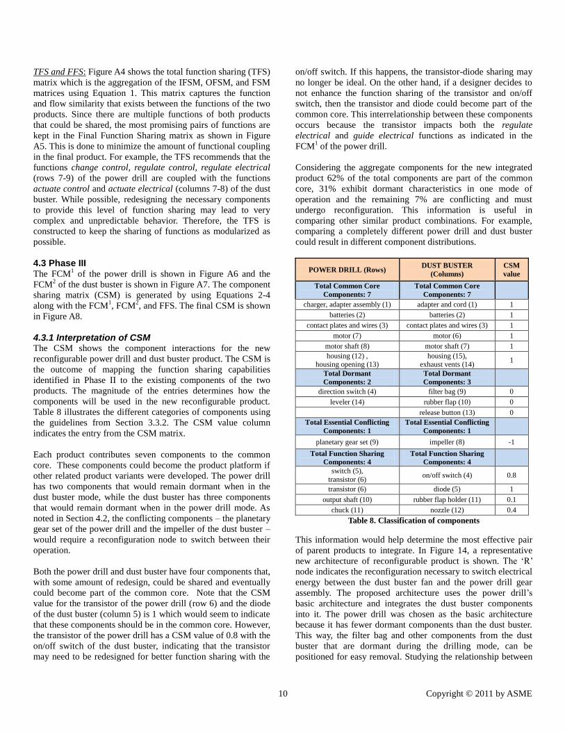
4.3.1 Interpretation of CSM The CSM shows the component interactions for the new
reconfigurable power drill and dust buster product. The CSM is
the outcome of mapping the function sharing capabilities
identified in Phase II to the existing components of the two
products. The magnitude of the entries determines how the
components will be used in the new reconfigurable product.
Table 8 illustrates the different categories of components using
the guidelines from Section 3.3.2. The CSM value column
indicates the entry from the CSM matrix.
Each product contributes seven components to the common
core. These components could become the product platform if
other related product variants were developed. The power drill
has two components that would remain dormant when in the
dust buster mode, while the dust buster has three components
that would remain dormant when in the power drill mode. As
noted in Section 4.2, the conflicting components – the planetary
gear set of the power drill and the impeller of the dust buster –
would require a reconfiguration node to switch between their
operation.
Both the power drill and dust buster have four components that,
with some amount of redesign, could be shared and eventually
could become part of the common core. Note that the CSM
value for the transistor of the power drill (row 6) and the diode
of the dust buster (column 5) is 1 which would seem to indicate
that these components should be in the common core. However,
the transistor of the power drill has a CSM value of 0.8 with the
on/off switch of the dust buster, indicating that the transistor
may need to be redesigned for better function sharing with the
on/off switch. If this happens, the transistor-diode sharing may
no longer be ideal. On the other hand, if a designer decides to
not enhance the function sharing of the transistor and on/off
switch, then the transistor and diode could become part of the
common core. This interrelationship between these components
occurs because the transistor impacts both the regulate
electrical and guide electrical functions as indicated in the
FCM1 of the power drill.
Considering the aggregate components for the new integrated
product 62% of the total components are part of the common
core, 31% exhibit dormant characteristics in one mode of
operation and the remaining 7% are conflicting and must
undergo reconfiguration. This information is useful in
comparing other similar product combinations. For example,
comparing a completely different power drill and dust buster
could result in different component distributions.
POWER DRILL (Rows) DUST BUSTER
(Columns)
CSM
value
Total Common Core
Components: 7
Total Common Core
Components: 7
charger, adapter assembly (1) adapter and cord (1) 1
batteries (2) batteries (2) 1
contact plates and wires (3) contact plates and wires (3) 1
motor (7) motor (6) 1
motor shaft (8) motor shaft (7) 1
housing (12) , housing opening (13)
housing (15), exhaust vents (14)
1
Total Dormant
Components: 2
Total Dormant
Components: 3
direction switch (4) filter bag (9) 0
leveler (14) rubber flap (10) 0
release button (13) 0
Total Essential Conflicting
Components: 1
Total Essential Conflicting
Components: 1
planetary gear set (9) impeller (8) -1
Total Function Sharing
Components: 4
Total Function Sharing
Components: 4
switch (5),
transistor (6) on/off switch (4) 0.8
transistor (6) diode (5) 1
output shaft (10) rubber flap holder (11) 0.1
chuck (11) nozzle (12) 0.4
Table 8. Classification of components
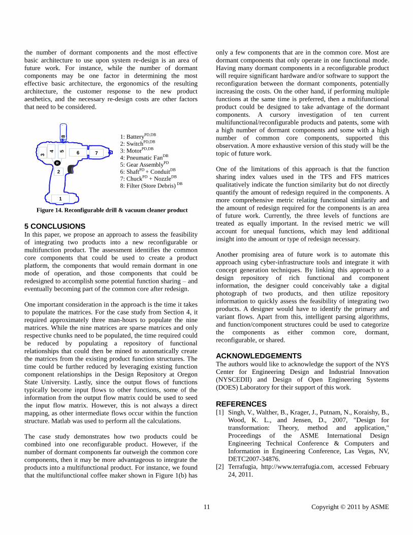
This information would help determine the most effective pair
of parent products to integrate. In Figure 14, a representative
new architecture of reconfigurable product is shown. The „R‟
node indicates the reconfiguration necessary to switch electrical
energy between the dust buster fan and the power drill gear
assembly. The proposed architecture uses the power drill‟s
basic architecture and integrates the dust buster components
into it. The power drill was chosen as the basic architecture
because it has fewer dormant components than the dust buster.
This way, the filter bag and other components from the dust
buster that are dormant during the drilling mode, can be
positioned for easy removal. Studying the relationship between
11 Copyright © 2011 by ASME
the number of dormant components and the most effective
basic architecture to use upon system re-design is an area of
future work. For instance, while the number of dormant
components may be one factor in determining the most
effective basic architecture, the ergonomics of the resulting
architecture, the customer response to the new product
aesthetics, and the necessary re-design costs are other factors
that need to be considered.
1: BatteryPD,DB
2: SwitchPD,DB
3: MotorPD,DB
4: Pneumatic FanDB
5: Gear AssemblyPD
6: ShaftPD + ConduitDB
7: ChuckPD + NozzleDB
8: Filter (Store Debris) DB
Figure 14. Reconfigurable drill & vacuum cleaner product
5 CONCLUSIONS In this paper, we propose an approach to assess the feasibility
of integrating two products into a new reconfigurable or
multifunction product. The assessment identifies the common
core components that could be used to create a product
platform, the components that would remain dormant in one
mode of operation, and those components that could be
redesigned to accomplish some potential function sharing – and
eventually becoming part of the common core after redesign.
One important consideration in the approach is the time it takes
to populate the matrices. For the case study from Section 4, it
required approximately three man-hours to populate the nine
matrices. While the nine matrices are sparse matrices and only
respective chunks need to be populated, the time required could
be reduced by populating a repository of functional
relationships that could then be mined to automatically create
the matrices from the existing product function structures. The
time could be further reduced by leveraging existing function
component relationships in the Design Repository at Oregon
State University. Lastly, since the output flows of functions
typically become input flows to other functions, some of the
information from the output flow matrix could be used to seed
the input flow matrix. However, this is not always a direct
mapping, as other intermediate flows occur within the function
structure. Matlab was used to perform all the calculations.
The case study demonstrates how two products could be
combined into one reconfigurable product. However, if the
number of dormant components far outweigh the common core
components, then it may be more advantageous to integrate the
products into a multifunctional product. For instance, we found
that the multifunctional coffee maker shown in Figure 1(b) has
only a few components that are in the common core. Most are
dormant components that only operate in one functional mode.
Having many dormant components in a reconfigurable product
will require significant hardware and/or software to support the
reconfiguration between the dormant components, potentially
increasing the costs. On the other hand, if performing multiple
functions at the same time is preferred, then a multifunctional
product could be designed to take advantage of the dormant
components. A cursory investigation of ten current
multifunctional/reconfigurable products and patents, some with
a high number of dormant components and some with a high
number of common core components, supported this
observation. A more exhaustive version of this study will be the
topic of future work.
One of the limitations of this approach is that the function
sharing index values used in the TFS and FFS matrices
qualitatively indicate the function similarity but do not directly
quantify the amount of redesign required in the components. A
more comprehensive metric relating functional similarity and
the amount of redesign required for the components is an area
of future work. Currently, the three levels of functions are
treated as equally important. In the revised metric we will
account for unequal functions, which may lend additional
insight into the amount or type of redesign necessary.
Another promising area of future work is to automate this
approach using cyber-infrastructure tools and integrate it with
concept generation techniques. By linking this approach to a
design repository of rich functional and component
information, the designer could conceivably take a digital
photograph of two products, and then utilize repository
information to quickly assess the feasibility of integrating two
products. A designer would have to identify the primary and
variant flows. Apart from this, intelligent parsing algorithms,
and function/component structures could be used to categorize
the components as either common core, dormant,
reconfigurable, or shared.
ACKNOWLEDGEMENTS The authors would like to acknowledge the support of the NYS
Center for Engineering Design and Industrial Innovation
(NYSCEDII) and Design of Open Engineering Systems
(DOES) Laboratory for their support of this work.
REFERENCES [1] Singh, V., Walther, B., Krager, J., Putnam, N., Koraishy, B.,
Wood, K. L., and Jensen, D., 2007, "Design for
transformation: Theory, method and application,"
Proceedings of the ASME International Design
Engineering Technical Conference & Computers and
Information in Engineering Conference, Las Vegas, NV,
DETC2007-34876.
[2] Terrafugia, http://www.terrafugia.com, accessed February
24, 2011.
1
3 4
R
65 7
8
2
12 Copyright © 2011 by ASME
[3] Kalorik Toaster Oven/Coffee Maker/Griddle,
http://www.amazon.com/Kalorik-Toaster-Coffee-Maker-
Griddle/dp/B002V0R1L8, accessed December 10, 2010.
[4] Simpson, T. W., Siddique, Z., and Jiao, J., 2005, Product
platform and product family design: Methods and
applications, Springer, New York.
[5] Pine, J. B., 1992, "Mass customization: the new frontier in
business competition," Harvard Business School Press,
Boston.
[6] Katz, R., 2007, "Design principles of reconfigurable
machines," International Journal of Advanced
Manufacturing Technology, 34(2007), pp. 430-439.
[7] Schulz, A. P., Fricke, E., and Igenbergs, E., 2000,
"Enabling changes in systems throughout the entire life-
cycle - key to success?," Proceedings of the 10th Annual
INCOSE Conference, Minneapolis, MN, USA.
[8] Saleh, J. H., Mark, G., and Jordan, N. C., 2009,
"Flexibility: a multi-disciplinary literature review and a
research agenda for designing flexible engineering
systems," Journal of Engineering Design, 20(3), pp. 307-
323.
[9] Ferguson, S., Siddiqi, A., Lewis, K., and De Weck, O. L.,
2007, "Flexible and reconfigurable systems: nomenclature
and review," Proceedings of the ASME International
Design Engineering Technical Conference & Computers
and Information in Engineering Conference, Las Vegas,
NV, DETC2007-35745.
[10] Singh, V., Skiles, S. M., Krager, J. E., Wood, K. L.,
Szmerekovsky, A., and Jensen, D., 2009, "Innovations in
design through transformation: a fundamental study of
transformation principles," Journal of Mechanical Design,
131(8), p. 081010.
[11] Haldaman, J., and Parkinson, M., 2010, "Reconfigurable
products and their means of reconfiguration," Proceedings
of the ASME International Design Engineering Technical
Conferences & Computers and Information in Engineering
Conference, Montreal, Quebec, Canada, DETC2010-
28528.
[12] Skiles, S. M., Singh, V., Krager, J., Seepersad, C. C.,
Wood, K., and Jensen, D., 2006, "Adapted concept
generation and computational techniques for the
application of a transformer theory," Proceedings of ASME
International Design Engineering Technical Conferences
and Computer and Information in Engineering Conference,
Philadelphia, PA, DETC2006-99584.
[13] Weaver, J. M., Wood, K. L. and Jensen, D. , 2008,
"Transformation facilitators: a quantitative analysis of
reconfigurable products and their characterstics,"
Proceedings of the ASME International Design
Engineering Technical Conference & Computers and
Information in Engineering Conference, Brooklyn, NY,
DETC2008-49891.
[14] Weaver, J. M., Kuhr, R., Wang, D., Crawford, R. H., Wood,
K. L., Jensen, D., and Linsey, J. S., 2009, "Increasing
innovation in multi-function systems: Evaluation and
experimentation of two ideation methods for design,"
Proceedings of the ASME International Design
Engineering Technical Conferences & Computers and
Information in Engineering Conference, San Diego, CA,
DETC2009-86256
[15] Kuhr, R., Wood, K. L., Jensen, D., and Crawford, R., 2010,
"Concept opportunity diagrams, a visual modeling method
to find multifunctional design concepts," Proceedings of
the ASME International Design Engineering Technical
Conference & Computers and Information in Engineering
Conference, Montreal, Quebec, DETC2010-29068.
[16] Ferguson, S., and Lewis, K., 2006, "Effective development
of reconfigurable systems using linear state-feedback
control," AIAA Journal, 44(4), pp. 868-878.
[17] Olewnik, A., and Lewis, K., 2006, "A decision support
framework for flexible system design," Journal of
Engineering Design, 17(1), pp. 75-97.
[18] Siddiqi, A., and De Weck, O. L., 2008, "Modeling methods
and conceptual design principles for reconfigurable
systems," Journal of Mechanical Design, 130(10), p.
10110.
[19] Siddiqi, A., De Weck, O. L., and Iagnemma, K., 2006,
"Reconfigurability in planetary surface vehicles: Modeling
approaches and case study," Journal of the British
Interplanetary Society, 59(12), pp. 450-460.
[20] Khire, R. A., and Messac, A., 2006, "Selection-integrated
optimization (SIO) methodology for optimal design of
adaptive systems," Proceedings of the ASME International
Design Engineering Technical Conference & Computers
and Information in Engineering Conference, Philadephia,
PA, DETC2006-99322.
[21] Lewis, P. K., Mattson, C. A., and Murray, V. R., 2010, "An
engineering design strategy for reconfigurable products
that support poverty alleviation," Proceedings of the ASME
International Design Engineering Technical Conferences &
Computers and Information in Engineering Conferences,
Montreal, Quebec, Canada, DETC2010-28739.
[22] Ulrich, K. T., and Eppinger, S. D., 1995, Product design
and development, McGraw-Hill, New York, NY.
[23] Ulrich, K., 1993, "The role of product architecture in
manufacturing firm," Research Policy, 24(1995), pp. 419-
440.
[24] Deng, Y. M., Britton, G. A., and Tor, S. B., 1998, "A design
perspective of mechanical function and its object-oriented
representation scheme," Engineering with Computers,
14(4), pp. 309-320.
[25] Otto, K., and Wood, K., 2000, Product design: techniques
in reverse engineering and new product development,
Prentice Hall, Upper Saddle River, NJ.
[26] Hirtz, J., Stone, R. B., McAdams, D. A., Szykman, S., and
Wood, K. L., 2002, "A functional basis for engineering
design: reconciling and evolving previous efforts,"
Research in Engineering Design, 13(2), pp. 65–82.
[27] Kurtoglu, T., and Campbell, M. I., 2009, "Automated
synthesis of eletcromechanical design configuration from
empirical analysis of function to form mapping," Journal of
Engineering Design, 20(1), pp. 83-104.
13 Copyright © 2011 by ASME
[28] Bryant, C. R., McAdams, D. A., Stone, R. B., Kurtoglu, T.,
and Campell, M. I., 2005, "A computational technique for
concept generation," Proceedings of the ASME
International Design Engineering Technical Conferences &
Computers and Information in Engineering Conference,
Long Beach, CA, DETC2005-85323.
[29] Kurtoglu, T., Campbell, M. I., Arnold, C. B., Stone, R., and
McAdams, D. A., 2009, "A component taxonomy as a
framework for computational design analysis," Journal of
Computing and Information Science in Engineering, 9(1),
p. 011007.
[30] Bohm, M. R., and Stone, R. B., 2010, "Form follows form
- fine tuning artificial intelligence method," Proceedings of
the ASME International Design Engineering Technical
Conferences & Computers and Information in Engineering
Conference, Montreal, Quebec, Canada, DETC2010-
28774.
[31] Stone, R. B., Wood, K. L., and Crawford, R. H., 2000, "A
heuristic method for identifying modules for product
architecture," Design Studies, 21(1), pp. 5-31.
[32] Zamirowski, E. J., and Otto, K. N., 1999, "Identifying
product portfolio architecture modularity using function
and variety heuristics," Proceedings of the 11th
International Conference on Design Theory and
Methodology ASME Design Engineering Technical
Conferences, Las Vegas, NV, DETC99/DTM-8790.
[33] Steward, D., 1981, "The design structure matrix: A method
for managing the design of complex systems," IEEE
Transactions on Engineering Management, EM-28(3), pp.
71-74.
[34] Browning, T. R., 2001, "Applying the design structure
matrix to system decomposition and integration problems:
A review and new directions," IEEE Transaction on
Engineering Management, 48(3), pp. 292-305.
[35] Vucovich, J., Bhardwaj, N., Hoi-Hei, H., Ramakrishna, M.,
Thakur, M., and Stone, R., 2006, "Concept generation
algorithms for repository-based early design," Proceedings
of the ASME International Design Engineering Technical
Conference & Computers and Information in Engineering
Conference, Philadephia, PA, DETC2006-99466.
[36] McAdams, D. A., and Wood, K. L., 2002, "A Quantitative
similarity metric for design-by-analogy," Journal of
Mechanical Design, 124(2), pp. 174-182.
[37] Ulrich, K., and Seering, W. P., 1988, "Function sharing in
mechanical design," AAAI-88 Proceedings, Common
Sense Reasoning, pp. 342-346.
[38] Yu, T. L., Yassine, A., and Goldberg, D. E., 2003, "A
genetic algorithm for developing modular product
architectures," Proceedings of ASME Design Engineering
Technical Conferences and Computers and Information in
Engineering Conference, Chicago, IL, DETC2003/DTM-
48657.
[39] Design Repository, Design Engineering Laboratory,
http://designengineeringlab.org/delabsite/repository.html,
accessed January 10, 2011.
[40] Altshuller G.S., 1984, Creativity as an exact science: The
theory of the solution of inventive problems, Gordon and
Breach, New York.
14 Copyright © 2011 by ASME
APPENDIX
Figure A1. Input flow descriptors sharing matrix
Figure A2. Output Flow descriptors Sharing Matrix
imp
ort
ele
ctri
cal
chan
ge e
lect
rica
l
exp
ort
ele
ctri
cal
sup
ply
ele
ctri
cal
sto
re e
lect
rica
l
tran
sfe
r e
lect
rica
l
actu
ate
co
ntr
ol
actu
ate
ele
ctri
cal
guid
e e
lect
rica
l
con
vert
ele
ctri
cal t
o
me
chan
ical
tran
sfe
r m
ech
anic
al
con
vert
me
chan
ical
to
pn
eu
mat
ic
sep
arat
e m
ixtu
re
sto
re s
olid
sto
p s
olid
guid
e m
ixtu
re
imp
ort
mix
ture
guid
e m
ixtu
re
imp
ort
hu
man
mat
eri
al
stab
ilize
me
chan
ical
secu
re s
olid
exp
ort
gas
1 2 3 4 5 6 7 8 9 10 11 12 13 14 15 16 17 18 19 20 21 22
import electrical 1 1 0 0 0 0 0 0 0 0 0 0 0 0 0 0 0 0 0 0 0 0 0
change electrical 2 0 1 0 0 0 0 0 0 0 0 0 0 0 0 0 0 0 0 0 0 0 0
export electrical 3 0 0 1 0 0 0 0 0 0 0 0 0 0 0 0 0 0 0 0 0 0 0
supply electrical 4 0 0 0 1 0 0 0 0 0 0 0 0 0 0 0 0 0 0 0 0 0 0
store electrical 5 0 0 0 0 1 0 0 0 0 0 0 0 0 0 0 0 0 0 0 0 0 0
transfer Electrical 6 0 0 0 0 0 1 0 0 0 0 0 0 0 0 0 0 0 0 0 0 0 0
change Control 7 0 0 0 0 0 0 1 0 0 0 0 0 0 0 0 0 0 0 0 0 0 0
regulate control 8 0 0 0 0 0 0 1 0 0 0 0 0 0 0 0 0 0 0 0 0 0 0
regulate electrical 9 0 0 0 0 0 0 0 1 0 0 0 0 0 0 0 0 0 0 0 0 0 0
guide electrical 10 0 0 0 0 0 0 0 0 1 0 0 0 0 0 0 0 0 0 0 0 0 0
convert electrical to mechanical 11 0 0 0 0 0 0 0 0 0 1 0 0 0 0 0 0 0 0 0 0 0 0
transfer Mechanical 12 0 0 0 0 0 0 0 0 0 0 1 0 0 0 0 0 0 0 0 0 0 0
change mechanical 13 0 0 0 0 0 0 0 0 0 0 0 -1 0 0 0 0 0 0 0 0 0 0
transfer mechanical 14 0 0 0 0 0 0 0 0 0 0 0 0 0 0 0 0 0 0 0 0 0 0
rotate solid 15 0 0 0 0 0 0 0 0 0 0 0 0 0.3 0.7 0.7 0.3 0.3 0.3 0 0 0 0
secure solid 16 0 0 0 0 0 0 0 0 0 0 0 0 0 0 0 0 0 0 0.3 0 1 0.3
indicate status 17 0 0 0 0 0 0 0 0 0 0 0 0 0 0 0 0 0 0 0 0 0 0export gas /
import gas 18 0 0 0 0 0 0 0 0 0 0 0 0 0 0 0 0 0 0 0.3 0 0.3 1
IFSM
Parent Product #2
Dust-Buster
Common Core Chunk-1 & 2 RCFG Chunk - 3 Auxiliary Chunk - 4
Par
en
t P
rod
uct
#1
Po
we
r D
rill
Co
mm
on
Co
re C
hu
nk
- 1
& 2
RC
FG
Ch
un
k -
3
Au
xilia
ry
Ch
un
k -
4
imp
ort
ele
ctri
cal
chan
ge e
lect
rica
l
exp
ort
ele
ctri
cal
sup
ply
ele
ctri
cal
sto
re e
lect
rica
l
tran
sfe
r e
lect
rica
l
actu
ate
co
ntr
ol
actu
ate
ele
ctri
cal
guid
e e
lect
rica
l
con
vert
ele
ctri
cal t
o
me
chan
ical
tran
sfe
r m
ech
anic
al
con
vert
me
chan
ical
to
pn
eu
mat
ic
sep
arat
e m
ixtu
re
sto
re s
olid
sto
p s
olid
guid
e m
ixtu
re
imp
ort
mix
ture
guid
e m
ixtu
re
imp
ort
hu
man
mat
eri
al
stab
ilize
me
chan
ical
secu
re s
olid
exp
ort
gas
1 2 3 4 5 6 7 8 9 10 11 12 13 14 15 16 17 18 19 20 21 22
import electrical 1 1 0 0 0 0 0 0 0 0 0 0 0 0 0 0 0 0 0 0 0 0 0
change electrical 2 0 1 0 0 0 0 0 0 0 0 0 0 0 0 0 0 0 0 0 0 0 0
export electrical 3 0 0 1 0 0 0 0 0 0 0 0 0 0 0 0 0 0 0 0 0 0 0
supply electrical 4 0 0 0 1 0 0 0 0 0 0 0 0 0 0 0 0 0 0 0 0 0 0
store electrical 5 0 0 0 0 1 0 0 0 0 0 0 0 0 0 0 0 0 0 0 0 0 0
transfer Electrical 6 0 0 0 0 0 1 0 0 0 0 0 0 0 0 0 0 0 0 0 0 0 0
change Control 7 0 0 0 0 0 0 1 0 0 0 0 0 0 0 0 0 0 0 0 0 0 0
regulate control 8 0 0 0 0 0 0 1 0 0 0 0 0 0 0 0 0 0 0 0 0 0 0
regulate electrical 9 0 0 0 0 0 0 0 1 0 0 0 0 0 0 0 0 0 0 0 0 0 0
guide electrical 10 0 0 0 0 0 0 0 0 1 0 0 0 0 0 0 0 0 0 0 0 0 0
convert electrical to mechanical 11 0 0 0 0 0 0 0 0 0 1 0 0 0 0 0 0 0 0 0 0 0 0
transfer Mechanical 12 0 0 0 0 0 0 0 0 0 0 1 0 0 0 0 0 0 0 0 0 0 0
change mechanical 13 0 0 0 0 0 0 0 0 0 0 0 -1 0 0 0 0 0 0 0 0 0 0
transfer mechanical 14 0 0 0 0 0 0 0 0 0 0 0 0 0 0 0 0 0 0 0 0 0 0
rotate solid 15 0 0 0 0 0 0 0 0 0 0 0 0 0.2 0.7 0.7 0.3 0.3 0.3 0 0 0 0
secure solid 16 0 0 0 0 0 0 0 0 0 0 0 0 0 0 0 0 0 0 0.3 0 1 0.3
indicate status 17 0 0 0 0 0 0 0 0 0 0 0 0 0 0 0 0 0 0 0 0 0 0export gas /
import gas 18 0 0 0 0 0 0 0 0 0 0 0 0 0 0 0 0 0 0 0.3 0 0.3 1
OFSM
Parent Product #2
Dust-Buster
Common Core Chunk-1 & 2 RCFG Chunk - 3 Auxiliary Chunk - 4
Par
en
t P
rod
uct
#1
Po
we
r D
rill
Co
mm
on
Co
re C
hu
nk
- 1
& 2
RC
FG
Ch
un
k -
3
Au
xilia
ry
Ch
un
k -
4
15 Copyright © 2011 by ASME
Figure A3. Function descriptors Sharing Matrix
Figure A4. Total Function Sharing Matrix
imp
ort
ele
ctri
cal
chan
ge e
lect
rica
l
exp
ort
ele
ctri
cal
sup
ply
ele
ctri
cal
sto
re e
lect
rica
l
tran
sfe
r e
lect
rica
l
actu
ate
co
ntr
ol
actu
ate
ele
ctri
cal
guid
e e
lect
rica
l
con
vert
ele
ctri
cal t
o
me
chan
ical
tran
sfe
r m
ech
anic
al
con
vert
me
chan
ical
to
pn
eu
mat
ic
sep
arat
e m
ixtu
re
sto
re s
olid
sto
p s
olid
guid
e m
ixtu
re
imp
ort
mix
ture
guid
e m
ixtu
re
imp
ort
hu
man
mat
eri
al
stab
ilize
me
chan
ical
secu
re s
olid
exp
ort
gas
1 2 3 4 5 6 7 8 9 10 11 12 13 14 15 16 17 18 19 20 21 22
import electrical 1 1 0 0 0 0 0 0 0 0 0 0 0 0 0 0 0 0 0 0 0 0 0
change electrical 2 0 1 0 0 0 0 0 0 0 0 0 0 0 0 0 0 0 0 0 0 0 0
export electrical 3 0 0 1 0 0 0 0 0 0 0 0 0 0 0 0 0 0 0 0 0 0 0
supply electrical 4 0 0 0 1 0 0 0 0 0 0 0 0 0 0 0 0 0 0 0 0 0 0
store electrical 5 0 0 0 0 1 0 0 0 0 0 0 0 0 0 0 0 0 0 0 0 0 0
transfer Electrical 6 0 0 0 0 0 1 0 0 0 0 0 0 0 0 0 0 0 0 0 0 0 0
change Control 7 0 0 0 0 0 0 0.3 0.3 0 0 0 0 0 0 0 0 0 0 0 0 0 0
regulate control 8 0 0 0 0 0 0 0.3 0.3 0 0 0 0 0 0 0 0 0 0 0 0 0 0
regulate electrical 9 0 0 0 0 0 0 0.3 0.3 0 0 0 0 0 0 0 0 0 0 0 0 0 0
guide electrical 10 0 0 0 0 0 0 0 0 1 0 0 0 0 0 0 0 0 0 0 0 0 0
convert electrical to mechanical 11 0 0 0 0 0 0 0 0 0 1 0 0 0 0 0 0 0 0 0 0 0 0
transfer Mechanical 12 0 0 0 0 0 0 0 0 0 0 1 0 0 0 0 0 0 0 0 0 0 0
change mechanical 13 0 0 0 0 0 0 0 0 0 0 0 -1 0 0 0 0 0 0 0 0 0 0
transfer mechanical 14 0 0 0 0 0 0 0 0 0 0 0 0 0 0 0 0.3 0.3 0.3 0 0 0 0
rotate solid 15 0 0 0 0 0 0 0 0 0 0 0 0 0 0 0 0.7 0.7 0.3 0 0 0 0
secure solid 16 0 0 0 0 0 0 0 0 0 0 0 0 0 0 0 0 0 0 0 0 1 0.3
indicate status 17 0 0 0 0 0 0 0 0 0 0 0 0 0 0 0 0 0 0 0 0 0 0export gas /
import gas 18 0 0 0 0 0 0 0 0 0 0 0 0 0 0 0 0 0 0 0.3 0 0.3 1
FSM
Parent Product #2
Dust-Buster
Common Core Chunk-1 & 2 RCFG Chunk - 3 Auxiliary Chunk - 4
Par
en
t P
rod
uct
#1
Po
we
r D
rill
Co
mm
on
Co
re C
hu
nk
- 1
& 2
RC
FG
Ch
un
k -
3
Au
xilia
ry
Ch
un
k -
4
imp
ort
ele
ctri
cal
chan
ge e
lect
rica
l
exp
ort
ele
ctri
cal
sup
ply
ele
ctri
cal
sto
re e
lect
rica
l
tran
sfe
r e
lect
rica
l
actu
ate
co
ntr
ol
actu
ate
ele
ctri
cal
guid
e e
lect
rica
l
con
vert
ele
ctri
cal t
o
me
chan
ical
tran
sfe
r m
ech
anic
al
con
vert
me
chan
ical
to
pn
eu
mat
ic
sep
arat
e m
ixtu
re
sto
re s
olid
sto
p s
olid
guid
e m
ixtu
re
imp
ort
mix
ture
guid
e m
ixtu
re
imp
ort
hu
man
mat
eri
al
stab
ilize
me
chan
ical
secu
re s
olid
exp
ort
gas
1 2 3 4 5 6 7 8 9 10 11 12 13 14 15 16 17 18 19 20 21 22
import electrical 1 1 0 0 0 0 0 0 0 0 0 0 0 0 0 0 0 0 0 0 0 0 0
change electrical 2 0 1 0 0 0 0 0 0 0 0 0 0 0 0 0 0 0 0 0 0 0 0
export electrical 3 0 0 1 0 0 0 0 0 0 0 0 0 0 0 0 0 0 0 0 0 0 0
supply electrical 4 0 0 0 1 0 0 0 0 0 0 0 0 0 0 0 0 0 0 0 0 0 0
store electrical 5 0 0 0 0 1 0 0 0 0 0 0 0 0 0 0 0 0 0 0 0 0 0
transfer Electrical 6 0 0 0 0 0 1 0 0 0 0 0 0 0 0 0 0 0 0 0 0 0 0
change Control 7 0 0 0 0 0 0 0.8 0.1 0 0 0 0 0 0 0 0 0 0 0 0 0 0
regulate control 8 0 0 0 0 0 0 0.8 0.1 0 0 0 0 0 0 0 0 0 0 0 0 0 0
regulate electrical 9 0 0 0 0 0 0 0.1 0.8 0 0 0 0 0 0 0 0 0 0 0 0 0 0
guide electrical 10 0 0 0 0 0 0 0 0 1 0 0 0 0 0 0 0 0 0 0 0 0 0
convert electrical to mechanical 11 0 0 0 0 0 0 0 0 0 1 0 0 0 0 0 0 0 0 0 0 0 0
transfer Mechanical 12 0 0 0 0 0 0 0 0 0 0 1 0 0 0 0 0 0 0 0 0 0 0
change mechanical 13 0 0 0 0 0 0 0 0 0 0 0 -1 0 0 0 0 0 0 0 0 0 0
transfer mechanical 14 0 0 0 0 0 0 0 0 0 0 0 0 0 0 0 0.1 0.1 0.1 0 0 0 0
rotate solid 15 0 0 0 0 0 0 0 0 0 0 0 0 0 0 0 0.4 0.4 0.3 0 0 0 0
secure solid 16 0 0 0 0 0 0 0 0 0 0 0 0 0 0 0 0 0 0 0 0 1 0.3
indicate status 17 0 0 0 0 0 0 0 0 0 0 0 0 0 0 0 0 0 0 0 0 0 0export gas /
import gas 18 0 0 0 0 0 0 0 0 0 0 0 0 0 0 0 0 0 0 0.3 0 0.3 1
TFS
Parent Product #2
Dust-Buster
Common Core Chunk-1 & 2 RCFG Chunk - 3 Auxiliary Chunk - 4
Par
en
t P
rod
uct
#1
Po
we
r D
rill
Co
mm
on
Co
re C
hu
nk
- 1
& 2
RC
FG
Ch
un
k -
3
Au
xilia
ry
Ch
un
k -
4
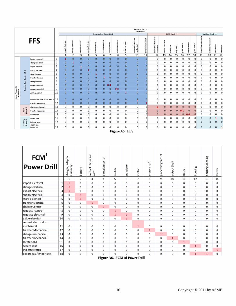
16 Copyright © 2011 by ASME
Figure A5. FFS
Figure A6. FCM of Power Drill
imp
ort
ele
ctri
cal
chan
ge e
lect
rica
l
exp
ort
ele
ctri
cal
sup
ply
ele
ctri
cal
sto
re e
lect
rica
l
tran
sfe
r e
lect
rica
l
actu
ate
co
ntr
ol
actu
ate
ele
ctri
cal
guid
e e
lect
rica
l
con
vert
ele
ctri
cal t
o
me
chan
ical
tran
sfe
r m
ech
anic
al
con
vert
me
chan
ical
to
pn
eu
mat
ic
sep
arat
e m
ixtu
re
sto
re s
olid
sto
p s
olid
guid
e m
ixtu
re
imp
ort
mix
ture
guid
e m
ixtu
re
imp
ort
hu
man
mat
eri
al
stab
ilize
me
chan
ical
secu
re s
olid
exp
ort
gas
1 2 3 4 5 6 7 8 9 10 11 12 13 14 15 16 17 18 19 20 21 22
import electrical 1 1 0 0 0 0 0 0 0 0 0 0 0 0 0 0 0 0 0 0 0 0 0
change electrical 2 0 1 0 0 0 0 0 0 0 0 0 0 0 0 0 0 0 0 0 0 0 0
export electrical 3 0 0 1 0 0 0 0 0 0 0 0 0 0 0 0 0 0 0 0 0 0 0
supply electrical 4 0 0 0 1 0 0 0 0 0 0 0 0 0 0 0 0 0 0 0 0 0 0
store electrical 5 0 0 0 0 1 0 0 0 0 0 0 0 0 0 0 0 0 0 0 0 0 0
transfer Electrical 6 0 0 0 0 0 1 0 0 0 0 0 0 0 0 0 0 0 0 0 0 0 0
change Control 7 0 0 0 0 0 0 0 0 0 0 0 0 0 0 0 0 0 0 0 0 0 0
regulate control 8 0 0 0 0 0 0 0.8 0 0 0 0 0 0 0 0 0 0 0 0 0 0 0
regulate electrical 9 0 0 0 0 0 0 0 0.8 0 0 0 0 0 0 0 0 0 0 0 0 0 0
guide electrical 10 0 0 0 0 0 0 0 0 1 0 0 0 0 0 0 0 0 0 0 0 0 0
convert electrical to mechanical 11 0 0 0 0 0 0 0 0 0 1 0 0 0 0 0 0 0 0 0 0 0 0
transfer Mechanical 12 0 0 0 0 0 0 0 0 0 0 1 0 0 0 0 0 0 0 0 0 0 0
change mechanical 13 0 0 0 0 0 0 0 0 0 0 0 -1 0 0 0 0 0 0 0 0 0 0
transfer mechanical 14 0 0 0 0 0 0 0 0 0 0 0 0 0 0 0 0.1 0 0 0 0 0 0
rotate solid 15 0 0 0 0 0 0 0 0 0 0 0 0 0 0 0 0 0.4 0 0 0 0 0
secure solid 16 0 0 0 0 0 0 0 0 0 0 0 0 0 0 0 0 0 0 0 0 1 0
indicate status 17 0 0 0 0 0 0 0 0 0 0 0 0 0 0 0 0 0 0 0 0 0 0export gas /
import gas 18 0 0 0 0 0 0 0 0 0 0 0 0 0 0 0 0 0 0 0 0 0 1
FFS
Parent Product #2
Dust-Buster
Common Core Chunk-1 & 2 RCFG Chunk - 3 Auxiliary Chunk - 4
Par
en
t P
rod
uct
#1
Po
we
r D
rill
Co
mm
on
Co
re C
hu
nk
- 1
& 2
RC
FG
Ch
un
k -
3
Au
xilia
ry
Ch
un
k -
4
FCM1
Power Drill
char
ger,
ad
apte
r
asse
mb
ly
bat
tery
con
tact
pla
tes
and
wir
es
dir
ecti
on
sw
itch
swit
ch
tran
sist
or
mo
tor
mo
tor
shaf
t
pla
net
ary
gear
set
ou
tpu
t Sh
aft
chu
ck
ho
usi
ng
ho
usi
ng
op
enin
g
leve
ler
1 2 3 4 5 6 7 8 9 10 11 12 13 14
import electrical 1 1 0 0 0 0 0 0 0 0 0 0 0 0 0
change electrical 2 1 0 0 0 0 0 0 0 0 0 0 0 0 0
export electrical 3 1 0 0 0 0 0 0 0 0 0 0 0 0 0
supply electrical 4 0 1 0 0 0 0 0 0 0 0 0 0 0 0
store electrical 5 0 1 0 0 0 0 0 0 0 0 0 0 0 0
transfer Electrical 6 0 0 1 0 0 0 0 0 0 0 0 0 0 0
change Control 7 0 0 0 1 0 0 0 0 0 0 0 0 0 0
regulate control 8 0 0 0 0 1 0 0 0 0 0 0 0 0 0
regulate electrical 9 0 0 0 0 1 1 0 0 0 0 0 0 0 0
guide electrical 10 0 0 0 0 0 1 0 0 0 0 0 0 0 0
convert electrical to
mechanical 11 0 0 0 0 0 0 1 0 0 0 0 0 0 0
transfer Mechanical 12 0 0 0 0 0 0 0 1 0 0 0 0 0 0
change mechanical 13 0 0 0 0 0 0 0 0 1 0 0 0 0 0
transfer mechancial 14 0 0 0 0 0 0 0 0 0 1 0 0 0 0
rotate solid 15 0 0 0 0 0 0 0 0 0 0 1 0 0 0
secure solid 16 0 0 0 0 0 0 0 0 0 0 0 1 0 0
indicate status 17 0 0 0 0 0 0 0 0 0 0 0 0 0 1
export gas / import gas 18 0 0 0 0 0 0 0 0 0 0 0 1 1 0
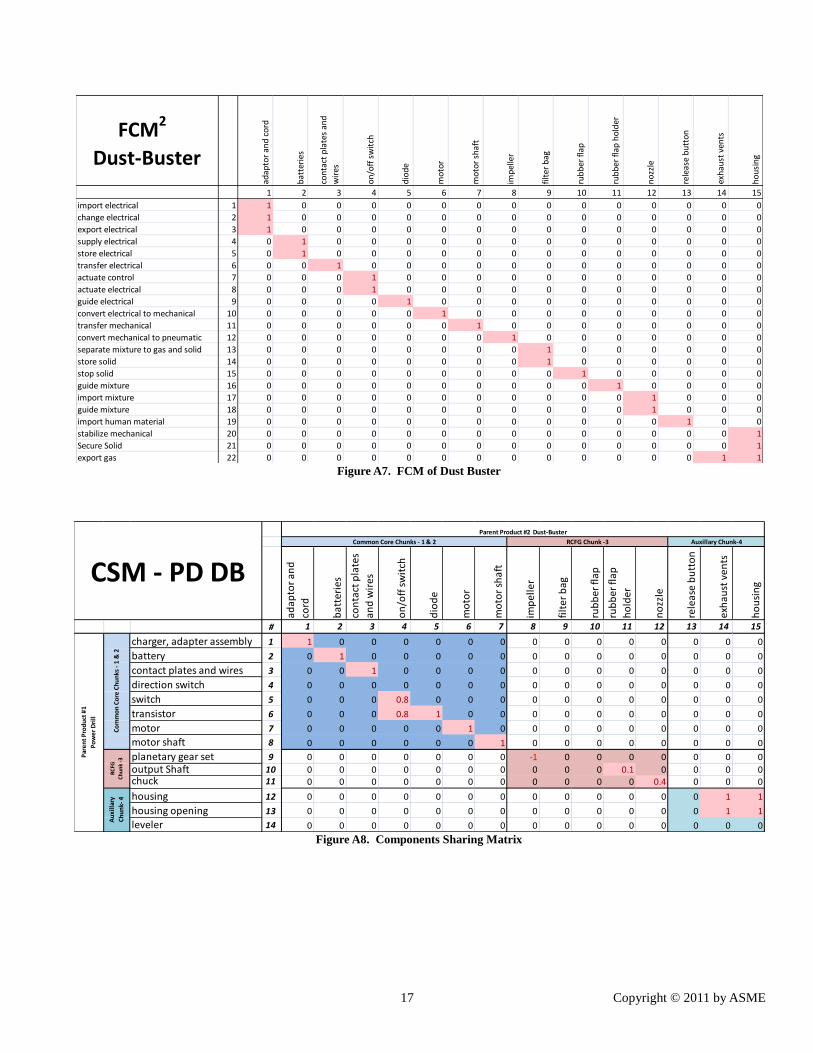
17 Copyright © 2011 by ASME
Figure A7. FCM of Dust Buster
Figure A8. Components Sharing Matrix
FCM2
Dust-Buster
adap
tor
and
co
rd
bat
teri
es
con
tact
pla
tes
and
wir
es
on
/off
sw
itch
dio
de
mo
tor
mo
tor
shaf
t
imp
elle
r
filt
er b
ag
rub
ber
fla
p
rub
ber
fla
p h
old
er
no
zzle
rele
ase
bu
tto
n
exh
aust
ven
ts
ho
usi
ng
1 2 3 4 5 6 7 8 9 10 11 12 13 14 15
import electrical 1 1 0 0 0 0 0 0 0 0 0 0 0 0 0 0
change electrical 2 1 0 0 0 0 0 0 0 0 0 0 0 0 0 0
export electrical 3 1 0 0 0 0 0 0 0 0 0 0 0 0 0 0
supply electrical 4 0 1 0 0 0 0 0 0 0 0 0 0 0 0 0
store electrical 5 0 1 0 0 0 0 0 0 0 0 0 0 0 0 0
transfer electrical 6 0 0 1 0 0 0 0 0 0 0 0 0 0 0 0
actuate control 7 0 0 0 1 0 0 0 0 0 0 0 0 0 0 0
actuate electrical 8 0 0 0 1 0 0 0 0 0 0 0 0 0 0 0
guide electrical 9 0 0 0 0 1 0 0 0 0 0 0 0 0 0 0
convert electrical to mechanical 10 0 0 0 0 0 1 0 0 0 0 0 0 0 0 0
transfer mechanical 11 0 0 0 0 0 0 1 0 0 0 0 0 0 0 0
convert mechanical to pneumatic 12 0 0 0 0 0 0 0 1 0 0 0 0 0 0 0
separate mixture to gas and solid 13 0 0 0 0 0 0 0 0 1 0 0 0 0 0 0
store solid 14 0 0 0 0 0 0 0 0 1 0 0 0 0 0 0
stop solid 15 0 0 0 0 0 0 0 0 0 1 0 0 0 0 0
guide mixture 16 0 0 0 0 0 0 0 0 0 0 1 0 0 0 0
import mixture 17 0 0 0 0 0 0 0 0 0 0 0 1 0 0 0
guide mixture 18 0 0 0 0 0 0 0 0 0 0 0 1 0 0 0
import human material 19 0 0 0 0 0 0 0 0 0 0 0 0 1 0 0
stabilize mechanical 20 0 0 0 0 0 0 0 0 0 0 0 0 0 0 1
Secure Solid 21 0 0 0 0 0 0 0 0 0 0 0 0 0 0 1
export gas 22 0 0 0 0 0 0 0 0 0 0 0 0 0 1 1
adap
tor
and
cord
bat
teri
es
con
tact
pla
tes
and
wir
es
on
/off
sw
itch
dio
de
mo
tor
mo
tor
shaf
t
imp
elle
r
filt
er b
ag
rub
ber
flap
rub
ber
flap
ho
lder
no
zzle
rele
ase
bu
tto
n
exh
aust
ven
ts
ho
usi
ng
# 1 2 3 4 5 6 7 8 9 10 11 12 13 14 15
charger, adapter assembly 1 1 0 0 0 0 0 0 0 0 0 0 0 0 0 0
battery 2 0 1 0 0 0 0 0 0 0 0 0 0 0 0 0
contact plates and wires 3 0 0 1 0 0 0 0 0 0 0 0 0 0 0 0
direction switch 4 0 0 0 0 0 0 0 0 0 0 0 0 0 0 0
switch 5 0 0 0 0.8 0 0 0 0 0 0 0 0 0 0 0
transistor 6 0 0 0 0.8 1 0 0 0 0 0 0 0 0 0 0
motor 7 0 0 0 0 0 1 0 0 0 0 0 0 0 0 0
motor shaft 8 0 0 0 0 0 0 1 0 0 0 0 0 0 0 0
planetary gear set 9 0 0 0 0 0 0 0 -1 0 0 0 0 0 0 0
output Shaft 10 0 0 0 0 0 0 0 0 0 0 0.1 0 0 0 0chuck 11 0 0 0 0 0 0 0 0 0 0 0 0.4 0 0 0
housing 12 0 0 0 0 0 0 0 0 0 0 0 0 0 1 1
housing opening 13 0 0 0 0 0 0 0 0 0 0 0 0 0 1 1
leveler 14 0 0 0 0 0 0 0 0 0 0 0 0 0 0 0
Parent Product #2 Dust-Buster
CSM - PD DB
Par
en
t P
rod
uct
#1
Po
we
r D
rill
Common Core Chunks - 1 & 2 RCFG Chunk -3 Auxillary Chunk-4
Au
xill
ary
Ch
un
k- 4
Co
mm
on
Co
re C
hu
nks
- 1
& 2
RC
FG
Ch
un
k -3


![Journal of Engineering Design - University at Buffalodoes.eng.buffalo.edu/DOES_Publications/2008/Dolan_Lewis...Downloaded By: [University at Buffalo (SUNY)] At: 13:33 27 May 2008 Journal](https://img.pdfslide.us/doc/110x75/5ec7d8ba721a6d486206c27a/journal-of-engineering-design-university-at-downloaded-by-university-at.jpg)