Embed Size (px)
Citation preview
A FULL ORDER SLIDING MODE TRACKING CONTROLLER
DESIGN FOR AN ELECTROHYDRAULIC CONTROL SYSTEM
RAFIDAH BTE NGADENGON @ NGADUNGON
UNVERSITI TEKNOLOGI MALAYSIA
A FULL ORDER SLIDING MODE TRACKING CONTROLLER DESIGN FOR AN ELECTROHYDRAULIC CONTROL SYSTEM
RAFIDAH BTE NGADENGON @ NGADUNGON
A project report submitted in partial fulfilment of the
requirements for a award of the degree of
Master of Engineering ( Electrical-Mechatronics and Automatic Control)
Faculty of Electrical Engineering
Universiti Teknologi Malaysia
APRIL 2005

iii
To my dearest father, mother and family for their encouragement and blessing
To my beloved fiance for his support and caring … … …

iv
ACKNOWLEDGEMENT
First of all, I am greatly indebted to ALLAH SWT on His blessing to make
this project successful.
I would like to express my gratitude to honourable Associate Professor Dr.
Mohamad Noh Ahmad, my supervisor of Master’s project. During the research, he
helped me a lot especially in guiding me, tried to give me encouragement and
assistance which finally leads me to the completion of this project.
I would like also to dedicate my appreciation to my parents, my family, my
fiance and my friends who helped me directly or indirectly help me in this project.
v
ABSTRACT
Electrohydraulic control system are widely use in industry due to continuous
operation, higher speed of response with fast motion etc. However, there is a
drawback that it is difficult to control because of the highly nonlinear and
parameters uncertainties. In this project, a Full Order Sliding Mode Controller is
design to control the system. First, the mathematical model of the electrohydraulic
servo control system is developed. Then the mathematic model will be transformed
into state space representation for the purposed of designing the controller. The
system will be treated as an uncertain system with bounded uncertainties where the
bounded are assumed known. The proposed controller will be designed based on
deterministic approach, such that the overall system is practically stable and tracks
the desired trajectory in spite the uncertainties and nonlinearities present in the
system. The performance and reliability of the proposal controller will be determined
by performing extensive simulation using MATLAB/SIMULINK. Lastly, the
performance of the controller is to be compared with Independent Joint Linear
Control and advanced deterministic controller.
vi
ABSTRAK
Sistem elektrohidraulik banyak digunakan secara meluas di industri kerana
operasi yang berterusan, tindakbalas halaju yang lebih tinggi dengan gerakan yang
pantas. Bagaimanapun kekurangan utama sistem ini ialah sukar untuk dikawal kerana
kadar ketaklelurusan yang tinggi dan wujudnya ketidak pastian parameter. Dalam
projek ini, sebuah pengawal ragam gelincir tertib penuh telah direkabentuk untuk
mengawal sistem. Tahap pertama melibatkan pembangunan model matematik
bersepadu yang mewakili sistem elektrohidraulik. Kemudian, model matematik
tersebut ditukar kepada perwakilan dalam bentuk keadaan ruang bagi tujuan
rekabentuk pengawal sepertimana telah dicadangkan. Sistem akan diperlakukan
sebagai sistem tidak pasti dengan ketidak pastian sempadan dimana had maksimum
sesetengah parameter dianggap diketahui. Pengawal yang dicadangkan akan
direkabentuk berdasarkan pada kaedah deterministic, dimana keseluruhan sistem
secara praktikalnya di anggap stabil dan mengikut kehendak trajektori. Walaupun
wujudnya ketidak pastian dan ketaklelurusan dalam sistem. Perlakuan atau simulasi
dan kebolehharapan cadangan kawalan akan ditentukan dengan bantuan perisian
MATLAB/SIMULINK. Akhir sekali, keupayaan diantara pengawal ragam gelincir
tertib penuh akan dibandingkan dengan kawalan lelurus bebas lipatan dan
deterministic kawalan termaju.
vii
CONTENTS
SUBJECT PAGE
TITLE i
DECLARATION ii
DEDICATION iii
ACKNOWLEDGEMENT iv
ABSTRACT v
ABSTRAK vi
CONTENTS vii
LIST OF FIGURES ix
LIST OF SYMBOLS x
LIST OF ABBREVIATIONS xii
CHAPTER 1 INTRODUCTION 1
1.1 Introduction 1
1.2 Objective 8
1.3 Scope of Project 9
1.4 Research Methodology 9
1.5 Literature Review 10
1.6 Thesis Layout 11
CHAPTER 2 MATHEMATICAL MODELLING 13
2.1 Introduction 13
2.2 Mathematical Modelling 14
2.3 System in State Space 16
viii
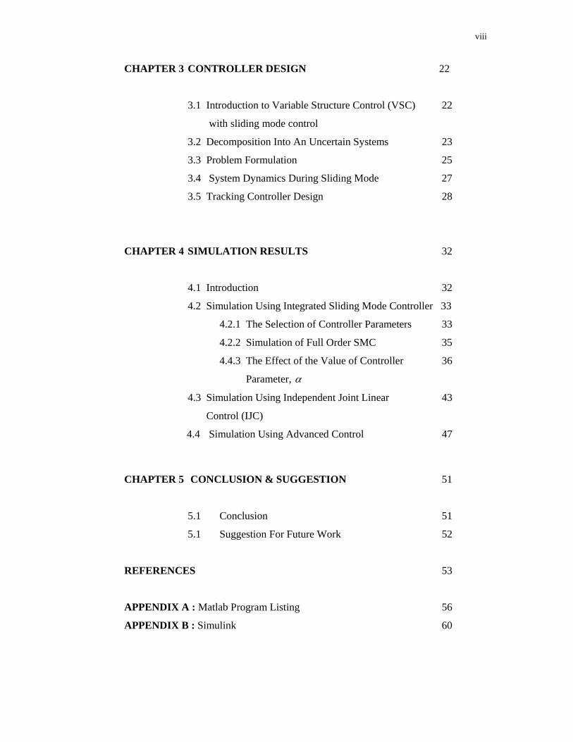
CHAPTER 3 CONTROLLER DESIGN 22
3.1 Introduction to Variable Structure Control (VSC) 22
with sliding mode control
3.2 Decomposition Into An Uncertain Systems 23
3.3 Problem Formulation 25
3.4 System Dynamics During Sliding Mode 27
3.5 Tracking Controller Design 28
CHAPTER 4 SIMULATION RESULTS 32
4.1 Introduction 32
4.2 Simulation Using Integrated Sliding Mode Controller 33
4.2.1 The Selection of Controller Parameters 33
4.2.2 Simulation of Full Order SMC 35
4.4.3 The Effect of the Value of Controller 36
Parameter, α
4.3 Simulation Using Independent Joint Linear 43
Control (IJC)
4.4 Simulation Using Advanced Control 47
CHAPTER 5 CONCLUSION & SUGGESTION 51
5.1 Conclusion 51
5.1 Suggestion For Future Work 52
REFERENCES 53
APPENDIX A : Matlab Program Listing 56
APPENDIX B : Simulink 60
ix
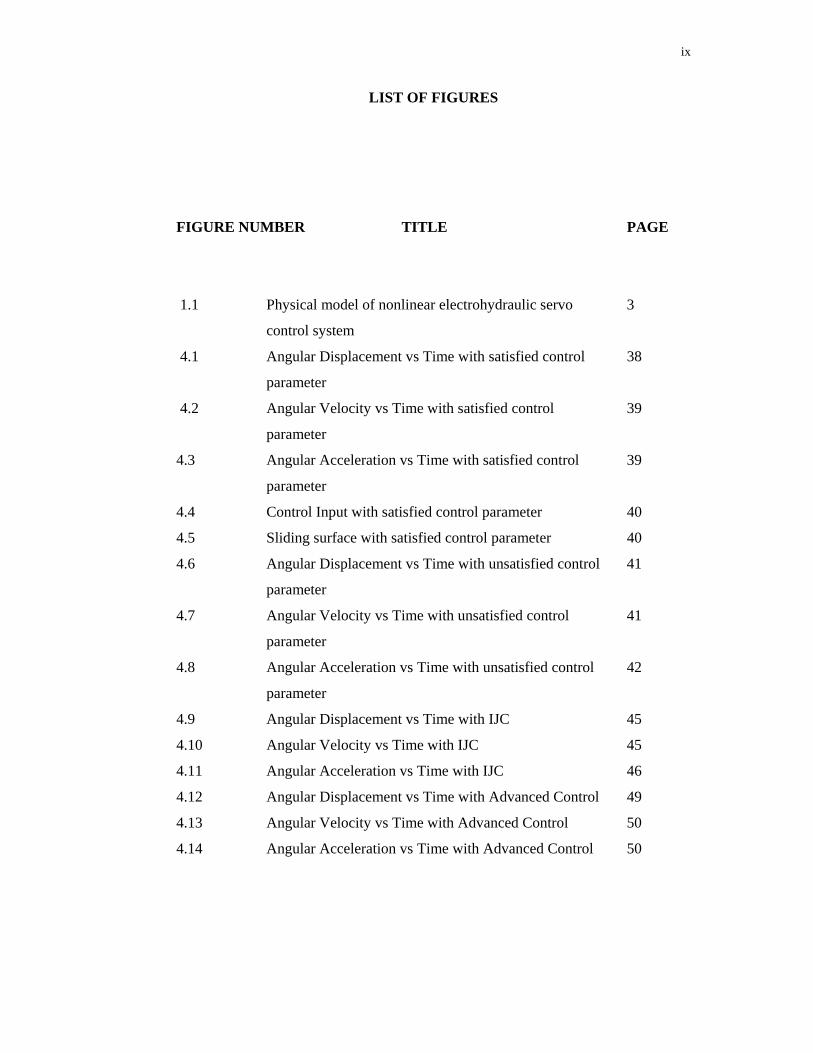
LIST OF FIGURES
FIGURE NUMBER TITLE PAGE
1.1 Physical model of nonlinear electrohydraulic servo 3
control system
4.1 Angular Displacement vs Time with satisfied control 38
parameter
4.2 Angular Velocity vs Time with satisfied control 39
parameter
4.3 Angular Acceleration vs Time with satisfied control 39
parameter
4.4 Control Input with satisfied control parameter 40
4.5 Sliding surface with satisfied control parameter 40
4.6 Angular Displacement vs Time with unsatisfied control 41
parameter
4.7 Angular Velocity vs Time with unsatisfied control 41
parameter
4.8 Angular Acceleration vs Time with unsatisfied control 42
parameter
4.9 Angular Displacement vs Time with IJC 45
4.10 Angular Velocity vs Time with IJC 45
4.11 Angular Acceleration vs Time with IJC 46
4.12 Angular Displacement vs Time with Advanced Control 49
4.13 Angular Velocity vs Time with Advanced Control 50
4.14 Angular Acceleration vs Time with Advanced Control 50
x
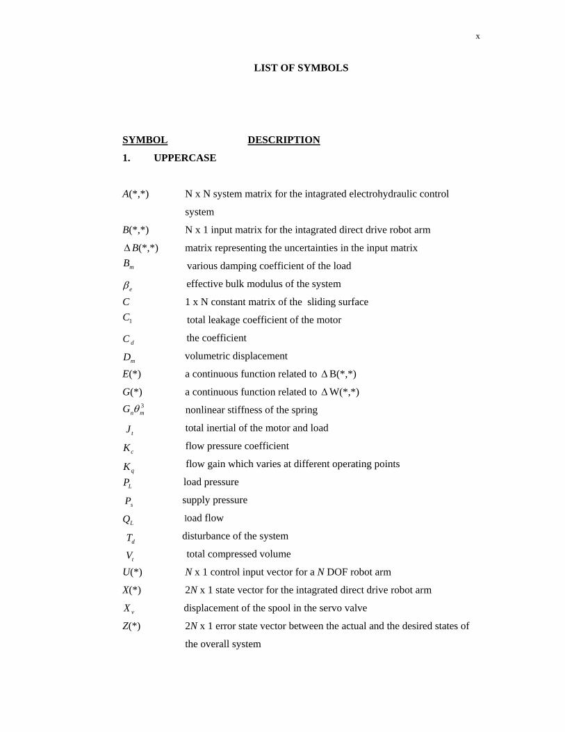
LIST OF SYMBOLS
SYMBOL DESCRIPTION
1. UPPERCASE
A(*,*) N x N system matrix for the intagrated electrohydraulic control
system
B(*,*) N x 1 input matrix for the intagrated direct drive robot arm
ΔB(*,*) matrix representing the uncertainties in the input matrix
various damping coefficient of the load
effective bulk modulus of the system
C 1 x N constant matrix of the sliding surface
total leakage coefficient of the motor
the coefficient
volumetric displacement
E(*) a continuous function related to ΔB(*,*)
G(*) a continuous function related to ΔW(*,*)
nonlinear stiffness of the spring
total inertial of the motor and load
flow pressure coefficient
flow gain which varies at different operating points
load pressure
supply pressure
load flow
disturbance of the system
total compressed volume
U(*) N x 1 control input vector for a N DOF robot arm
X(*) 2N x 1 state vector for the intagrated direct drive robot arm
displacement of the spool in the servo valve
Z(*) 2N x 1 error state vector between the actual and the desired states of
the overall system
1C
dC
mD
eβ
mB
qKcKtJ
LQ
LP
dT
tV
vX
3mnG θ
sP
xi
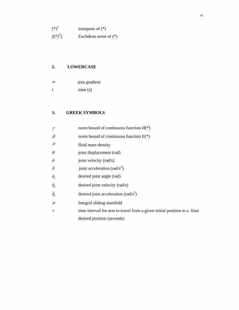
(*)T transpose of (*)
||(*)T|| Euclidean norm of (*)
2. LOWERCASE
area gradient
t time (s)
3. GREEK SYMBOLS
γ norm bound of continuous function H(*)
β norm bound of continuous function E(*)
fluid mass density
θ joint displacement (rad)
θ& joint velocity (rad/s)
θ&& joint acceleration (rad/s2)
dθ desired joint angle (rad)
dθ& desired joint velocity (rad/s)
dθ&& desired joint acceleration (rad/s2)
σ Integral sliding manifold
τ time interval for arm to travel from a given initial position to a final
desired position (seconds)
w
ρ
xii
LIST OF ABBREVIATIONS
IJC Independent Joint Control
LHP Left Half Plane
PI Proportional-Integral
PID Proportional-Integral-Derivative
SMC Sliding Mode Control
VSC Variable Structure Control
1
CHAPTER 1
INTRODUCTION
1.1 Introduction
Hydraulic servo system are widely used in industry due to their capabilities of
providing large driving force or torques, higher speed of response with fast motion and
possible speed reversals and continuous operation. Many industrial applications of
electrohydraulic servo systems are in a load condition application such as suspension
of electrohydraulic servo system, fly by wire system of aircraft, sheep steering gear
system and numerical machine tools. Electrohydraulic servo system combine together
the versatile and precision available from electrical technique of measurement and
signal processing with the superior performance which high pressure hydraulic
mechanism can provide when moving heavy loads and applying large forces. Servos
of this type are commonly used to operate the control surface of aircraft with actuators
which are very compact because they operate at high pressure.
2
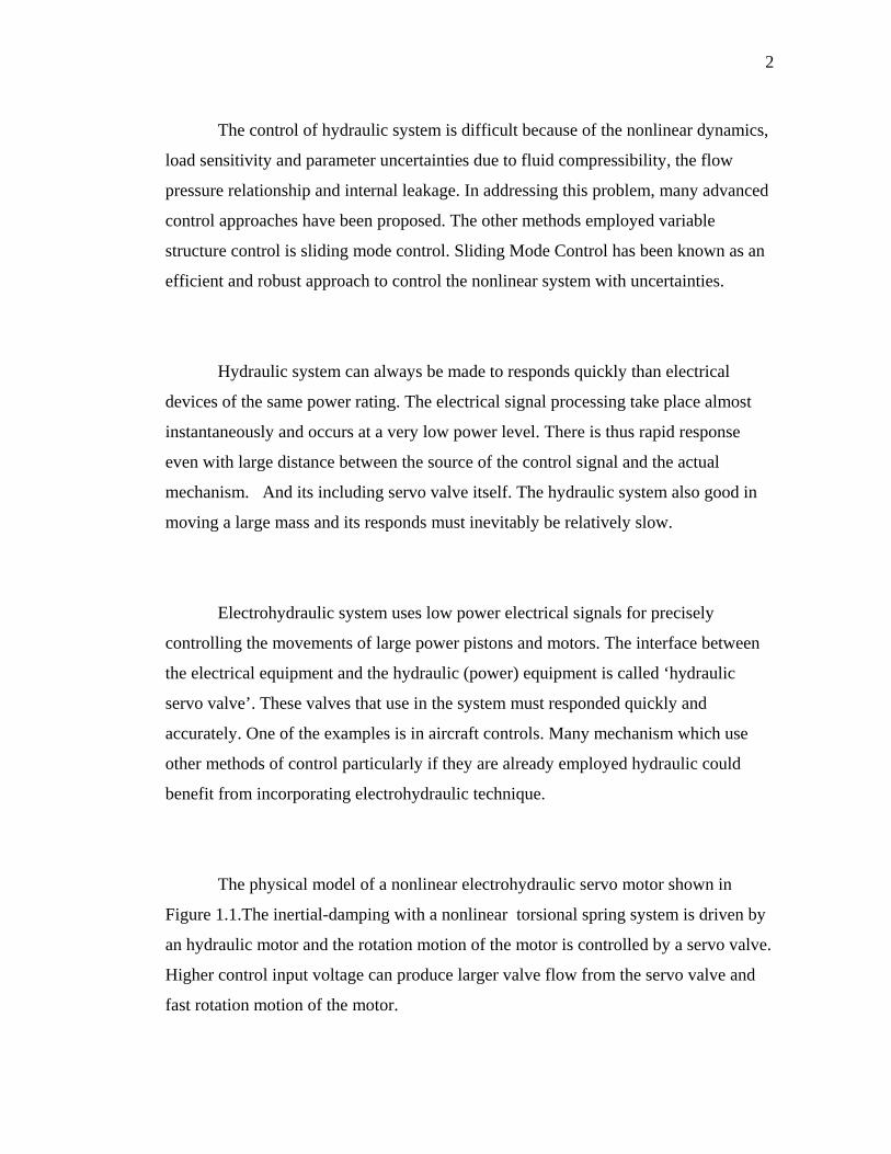
The control of hydraulic system is difficult because of the nonlinear dynamics,
load sensitivity and parameter uncertainties due to fluid compressibility, the flow
pressure relationship and internal leakage. In addressing this problem, many advanced
control approaches have been proposed. The other methods employed variable
structure control is sliding mode control. Sliding Mode Control has been known as an
efficient and robust approach to control the nonlinear system with uncertainties.
Hydraulic system can always be made to responds quickly than electrical
devices of the same power rating. The electrical signal processing take place almost
instantaneously and occurs at a very low power level. There is thus rapid response
even with large distance between the source of the control signal and the actual
mechanism. And its including servo valve itself. The hydraulic system also good in
moving a large mass and its responds must inevitably be relatively slow.
Electrohydraulic system uses low power electrical signals for precisely
controlling the movements of large power pistons and motors. The interface between
the electrical equipment and the hydraulic (power) equipment is called ‘hydraulic
servo valve’. These valves that use in the system must responded quickly and
accurately. One of the examples is in aircraft controls. Many mechanism which use
other methods of control particularly if they are already employed hydraulic could
benefit from incorporating electrohydraulic technique.
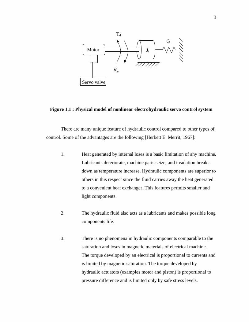
The physical model of a nonlinear electrohydraulic servo motor shown in
Figure 1.1.The inertial-damping with a nonlinear torsional spring system is driven by
an hydraulic motor and the rotation motion of the motor is controlled by a servo valve.
Higher control input voltage can produce larger valve flow from the servo valve and
fast rotation motion of the motor.
3
Figure 1.1 : Physical model of nonlinear electrohydraulic servo control system
There are many unique feature of hydraulic control compared to other types of
control. Some of the advantages are the following [Herbett E. Merrit, 1967]:
1. Heat generated by internal loses is a basic limitation of any machine.
Lubricants deteriorate, machine parts seize, and insulation breaks
down as temperature increase. Hydraulic components are superior to
others in this respect since the fluid carries away the heat generated
to a convenient heat exchanger. This features permits smaller and
light components.
2. The hydraulic fluid also acts as a lubricants and makes possible long
components life.
3. There is no phenomena in hydraulic components comparable to the
saturation and loses in magnetic materials of electrical machine.
The torque developed by an electrical is proportional to currents and
is limited by magnetic saturation. The torque developed by
hydraulic actuators (examples motor and piston) is proportional to
pressure difference and is limited only by safe stress levels.
Td
Motor
mθ
Servo valve
Jt
G
4
Therefore hydraulic actuators developed relatively large torques for
comparatively small devices.
4. Electrical motors are basically a simple lag device from applied
voltage to speed. Hydraulic actuators are basically a quadratic
resonance from flow to speed with a high natural frequency.
Therefore hydraulic actuators have a higher speed of response with
fast start, stop and speed reversal possible. Torque to inertia ratios
are large with resulting high acceleration capability. On the whole,
higher loop gains and bandwidths are possible with hydraulic
actuators in servo loops.
5. Hydraulic actuators may be operated under continuous, intermittent,
reversing and stalled condition without damage. With relief valve
protection, hydraulic actuators may be used for dynamics breaking.
Larger speed range are possible with hydraulic actuators. Both linear
and rotary actuators are available and add to the flexibility of
hydraulic power elements.
6. Hydraulic actuators have higher stiffness, that is inverse of slope of
speed-torque curves, compared to other drive deices since leakage
are low. There is a little drop in speed as loads are applied. In closed
loop system, this results in greater positional stiffness and less
position error.
7. Open and closed loop control of hydraulic actuators is relatively
simple using valve and pumps.
8. The transmission of power is moderately easy with hydraulic line.
Energy storage is relatively simple with accumulators.
5
Although hydraulic offers many distinct advantages, several advantages tend to
limit their use. Major disadvantages are the following [Herbett E. Merrit, 1967]:
1. Hydraulic power is not so readily available as that if electrical power.
This is not a serious threat to mobile and airborne application but most
certainly affect stationary application.
2. Small allowable tolerance results in high cost of hydraulic components.
3. The hydraulic fluid imposes an upper temperature limit. Fire and
explosion hazard exists if a hydraulic system is used near a source of
ignition. However, these situation have improved with the available of
high temperature and fire resistant fluids. Hydraulic systems are messy
because it is difficult to maintain a system free from leaks and there is
always a possibility of complete loss of fluid if a break in the system
occurs.
4. It is impossible to maintain the fluid free of dirt and contamination.
Contaminated oil can clog valve and actuators and, if the contaminant
is abrasive, cause a permanent loss in performance and failure.
Contaminated oil is the chief source of hydraulic control failure. Clean
oil and reliability are synonymous terms in hydraulic control.
5. Basic design procedure are lacking and difficult to obtain because of
the complexity of hydraulic control analysis. For example, the current
flow through a resistors is described by a simple law – Ohm’s law. In
contrast, no single law exists which describe the hydraulic resistance of
passages to flow. For this seemingly simple problem there are almost
endless details of Reynolds number, laminar or turbulent flow, passage
geometry, friction factors and discharge coefficients to cope with. This
factor limits the degree of sophistication of hydraulic control devices.
6
6. Hydraulics are not so flexible, linear, accurate and inexpensive as
electronics and electromechanical computation, error detection,
amplification, instrumentation and compensation. Therefore, hydraulic
devices are generally not desirable in the low power portions of control
systems.
The outstanding characteristic of hydraulic power elements have combined
with their comparative inflexibility at low power levels to make hydraulic control
attractive primarily in power portions of circuit and systems. The low power portions
of systems are usually accomplished by mechanical and electromechanical means.
All control system can be reduced to a few basic groups of elements, the
elements of each group performing a specific function in the system. The division into
group of elements can be carried out in a number of different ways, but selecting the
following four groups forms a convenient structure for the deviation of hydraulic and
electro-hydraulic system.
i) The power source.
ii) The control elements.
iii) The actuators.
iv) The data transmission elements.
The power source consists invariable of a pump or combination of pumps and
ancillary equipments, examples accumulators, relief valves, producing hydraulic
energy which is processed by the control elements to achieve the required operation of
the actuators. In system which have the supply pressure maintained at a constant level,
the hydraulic power source can be either a fixed or variable displacement pump.
The control elements control the output variable by manipulating the hydraulic
variables, pressure and flow. The input variable to the control elements are usually in
7
the form of mechanical, pneumatic, hydraulic or electrical signal. The input variable is
mostly a low power electrical or digital signal.
The actuator convert the hydraulic energy generated by the power source and
processed by the control elements into useful mechanical work. The actuator have
either a linear or rotary output, can be classified into cylinders or jacks, rotary
actuators and motors. The actuator producing linear output is referred as a cylinder or
jack.Cylinder can be either single acting or double acting. Single acting cylinders are
power driven in one direction only, while double acting cylinders are power driven in
both direction. Cylinder can be constructed as an single ended or double ended.
Double ended symmetric cylinder are frequently used for high performance servo
system, but have greater overall length and more expensive than single-ended
actuators. Single ended cylinder widely used for industrial and aerospace control
system cause of smaller size and lower cost.
Hydraulic motors are essentially hydraulic pumps in which the sense of energy
conversion has been reversed. While a pump converts mechanical energy supplied to
its drive shaft by a primary mover into hydraulic energy.The motor reconverts the
hydraulic energy provided by the pump into mechanical energy at its output shaft.
The control elements act on information received from the data transmission
elements. In a simple hydraulic control system the data transmission elements are
mechanical linkage or gears. But in complex systems data transmission can take at
many form for examples electrical, electronic, pneumatic and optical or combination
of these types of data transmission. The function of the data transmission elements is
to sense he controlled output quantity and to convert it to a signal which can be used
to either monitor the output or to act as a feedback devices in a closed loop control
8
system. The control output variable in a hydraulic operated force motion can be force,
velocity, position acceleration, pressure and flow.
1.2 Objective
The objectives of this research are as follows:
1. To transform the integrated nonlinear dynamic model of the Electrohydraulic
control system into a set of nonlinear uncertain model comprising the
nominal values and the bounded uncertainties. These structured uncertainties
exist due to the limit of the angular positions, speeds and accelerations.
2. To design a controller using the Full Order Sliding Mode Controll approach
and prove the stability of the system using Lyapunov approach.
3. To simulate the Electrohdraulic control system controlled by the Full Order
Sliding Mode Controller and to compare its performance with other
conventional controllers.
1.3 Scope of Project
The scopes of work for this project are
The electrohydraulic system considered is as described in [Rong-Fong Fung,
1997].
9
Design a controller using Full Order Sliding Mode Controller and prove that
the system is stable using Lyapunov approach.
A simulation study using MATLAB/Simulink as platform to prove the
effectiveness of this controller.
The performance of the Full Order Sliding Mode Controller is to be compared
with Independent Joint Linear Control (IJC) and advanced controller in [Yeoh
Aik Seng, 1998].
1.4 Research Methodology
The research work is undertaken in the following five developmental stages:
a) Decomposition of the complete model into an uncertain model.
b) Determination of the system dynamics during Sliding Mode.
c) Design a controller using Full Order Sliding Mode Control approach.
d) Prove the stability of the Full Order SMC controlled electrohydraulic system using
Lyapunov stability approach.
e) Perform simulation of this controller in controlling electroydraulic control system.
This simulation work will be carried out on MATLAB platform with Simulink as
it user interface.
f) Compare of the performance of Integral Sliding Mode Controller with
other controllers.
10
1.5 Literature Review
Electrohydraulic servomechanism is highly nonlinear with inherit parameter
uncertainties. Various type of Sliding Mode Control based on Variable Structure
Control has been proposed by researchers to control such a system. Some of the
existing results will be briefly outlined in this section.
In [ Rong-Fong Fung, 1997] a new technique of the variable structure control
is applied to an electrohydraulic servo control system which is described by third-
order nonlinear equation with time-varying coefficient. A two-phase variable structure
controller is designed to get the precise position control of an electrohydraulic servo
system. A reaching law method is implements to the control procedure, which make
fast response in the transient phase and good stability in the steady state of a nonlinear
hydraulic servo system.
Sliding mode control with time-varying switching gain and a time-varying
boundary level has been introduced in [L-C.Huang, 1996] to modify the traditional
sliding mode control with fixed switching gain and constant width bounded layer to
enhance the control performance of electrohydraulic position and different pressure.
Under certain condition, for a time-varying switching gain and boundary layer, the
combination of weighted position error and differential pressure can be asymptotically
tracked even when the system is subject to parameters uncertainties. One of the
important feature is to use only one input to simultaneously controls the angular
position and torque the electrohydraulic servo system in a different load condition.By
using this technique, the high frequency and large amplitude of control input are
attenuated.
11
An approach using variable structure control (VSC) with integral
compensation for an electrohydraulic position servo is presented in [Tzuen-Lih
Chern,1992]. The design involves the choice of the control function to guarantee the
existence of a sliding mode.The procedure include the determination of the switching
function and the control gain such that the system has an optimal motion with respect
to a quadratic performance index and the elimination of chattering of the control input.
[Miroslav Mihajlov, 2002] introduced a new technique of the sliding mode
control which is enhanced by fuzzy Proportional-Integral (PI) controller. The position
control problem in the presence of unmodelled dynamics, parametric uncertainties and
external disturbances was investigated. Fuzzy controller is added in the feedforward
branch of the closed loop in parallel with the Sliding Mode Controller with boundary
layer to improved the performance of the system.
1.6 Thesis Layout
This thesis contains five chapters. Chapter 2 deals with the mathematical
modelling of the Electrohydraulic control system. The formulation of the integrated
dynamic model of this electroydraulic is presented. The nonlinear differential equation
of the dynamics model of the system are derived then transform into state space
representations.
Chapter 3 presents the controller design using Full Order sliding mode control.
The Electrohydraulic control system is treated as an uncertain system. The model
comprising the nominal and bounded uncertain parts is computed, based on the
allowable range of the position, velocity and acceleration of the electrohydraulic servo
12
control system. It is shown mathematically that Full Order SMC is practically stable
using Lyapunov stability approach.
Chapter 4 shows some of the simulation results. The performance of the Full
Order sliding mode controller is evaluated by simulation study using Matlab/Simulink.
Chapter 5 conclude the work undertaken, suggestions for future are also
presented in this chapter.
53
REFERENCES
1. Ahmad M.N., Osman J.H. S., (2000). “A Controller Design for Electrohydraulic
Position Servo Control System”, Proc. TENCON, Vol.3, pp 314-318.
2. Ahmad M.N., Osman J.H. S., and Ghani M. R. A., (2002) “Sliding Mode Control
Of A Robot Manipulator Using Proportional Integral Switching Surface”, Proc.
IASTED Int. Conf. On Intelligent System and Control (ISC2002), Tsukuba, Japan,
pp 186-191.
3. Ahmad M.N., (2003). “Modelling And Control Of Direct Drive Robot
Manipulators”, Univerti Teknologi Malaysia , PhD Thesis.
4. Christopher Edwards and Sarah K. Spurgeon, (1998). “Sliding Mode Control:
Theory and Applications”, London: Taylor & Francis Group Ltd
5. F.D.Norvelle,(2000). “Electrohydraulic Control System”, Prantice Hall: New
Jersey.
54
6. Fung,R-H, Yang R-T., (1997). “Application of VSC in Position Control Of a
Nonlinear Electrohydraulic Servo System”, Pergamon, Vol 66, No 4, pp. 365-
372.
7. Fung,R-H., Wang Y-C., Yang R-T., and Huang H-H., (1997). “A variable
Structure Control with Proportional And Integral Compensation For
Electrohydraulic Position Servo Control System”, Mechatronics, 7, pp 67-81.
8. L-C-Hwang., (1996) “Sliding Mode Controller Using Time-varing Switching
Gain And Boundary Layer For Electrohydraulic Position And Different Pressure
Control”, IEEE. Proc-Control Theory Appl. Vol. 143, No 4.
9. Miroslav Mihajlov., (2002). “Position Control Of An Electrohydraulic Servo
System Using Sliding Mode Control Enhanced By Fuzzy PI Controller “, FACTA
UNIVERSITATIS, Series Mechanical Engineering, Vol 1, No 9, pp. 1217-123.
10. Q. P. Ha., H. Q. Nguyen., D.C. Rye., H.F. Durrant-Whyte., (1998). “Sliding
Mode Control with Fuzzy Tuning for an Electrohydraulic Position Servo System
“,IEEE Second International Conference on Knowledge-Based Intelligent
Electronic System, Vol 2, No 8, pp. 1516-873.
11. Tzuen-Lih Chern., (1992) “ An optimal Variable structure Control with Integral
Compensation For Electrohydraulic Position Servo Control Systems” IEEE
Transaction On Industrial Electronics, Vol 39, No 5.
55
12. Yeoh Aik Seng., (1998). “Advanced Control of Electrohydraulic Servo Control
System”, Universiti Teknologi Malaysia , PSM Thesis.
13. Young,K-K.D., (1988). “A variable Structure Model Following Control Design
for Robotics Application.” IEEE journal of Robotics and Automation, Vol 4, No
5, pp. 556-561.