Embed Size (px)
Citation preview
A Framework for the Metamodeling of Multi-variant Systems and
Reactive Simulation Model Generation and Execution
Thorsten Pawletta1, Artur Schmidt1, Umut Durak2, Bernard P. Zeigler3
1Hochschule Wismar – University of Applied Sciences, RG CEA, Wismar, Germany
2DLR Institute of Fligth Systems, Braunschweig, Germany
3RTSync Corp. and ACIMS Tucson/AZ, USA
The simulation-based study of Cyber-Physical Systems or complex production systems leads often to a vast
number of system variants. Each system variant is characterized by a particular model structure and parame-
ter settings, although system variants may also share common parts. There are two main approaches for
modeling such a set of system variants. On the one hand, all variants are mapped in a big model with varia-
tion points and on the other hand variants are specified on a higher level of abstraction using a metamodel
that is processed with appropriate transformation methods. This paper proposes an approach for modeling
system variants using the System Entity Structure (SES) Ontology. It introduces new concepts and advances
the SES by a procedural knowledge specification. Moreover, it proposes a software infrastructure for the au-
tomated and reactive generation and execution of simulation models based on a SES in combination with a
model base. Finally, it refers to a prototype implementation within MATLAB/Simulink and forward-looking
within Python.
1 Introduction
The study of multifaceted end user requirements of
Cyber-Physical Systems or of multi-variant produc-
tion systems leads to a vast number of system vari-
ants. Both problem types can be considered as a vari-
ability problem. Variability has been defined as the
ability of a system or an artefact to be configured,
customized or extended for employment in a particu-
lar context [1]. In software engineering Software
Product Lines (SPL) are widely employed for devel-
oping systems that are characterized by a high degree
of variability. SPL define variation points where dif-
ferent variants of products can be derived for varying
requirements [2]. Variability management has also
been introduced as a challenge to be tackled for mod-
el-based testing architectures [3], for model-based
concept development tools [4] and for studying multi-
variant production systems [5] or reactive robot con-
trols [6]. In this context the problem of reactiveness is
also discussed [5, 6, 7]. We will consider reactiveness
as the generation and execution of a new system
variant depending on current and previous results.
Variability mechanisms shall be defined at particular
levels of abstraction, ranging from metamodeling to
implementation of the source code. Using a meta-
model for variability modeling requires appropriate
model transformation methods for mapping to the
execution level. This is a particular challenge, be-
cause such methods are not supported by the estab-
lished modeling and simulation environments used in
the engineering or production system domain. Anoth-
er approach is the combination with software tools for
requirement or variant management [8] or with do-
main oriented tools [4]. However, in this case often
different kinds of models have to be maintained and
kept consistent.
For these are reasons, in engineering and production
system applications variability is still often encoded
within the executable system models. However, these
models are often hard to manage. Therefore, specific
modularization and configuration methods have been
developed to tackle the complexity. From the simula-
tion theory the approach of dynamic structure or
variable structure systems [9, 10] is known. On the
other side, rather pragmatic solutions have been de-
veloped, such as for the MATLAB/Simulink envi-
ronment in [11, 12].
For the modeling and simulation of modular, hierar-
chical systems, Zeigler introduced the System Entity
Structure (SES) for specifying a set of system config-
urations, called a family of systems. The SES ap-
proach has evolved steadily to an ontology for model
and data engineering [13, 14]. In combination with a
model base (MB), organizing a set of configurable
A Framework for the Metamodeling of Multi-variant Systems and Reactive Simulation Model Generation and Execution
basic models, the SES approach has been advanced to
a modeling and simulation framework (SES/MB)
[15]. In this paper, a reworked version of [16], we
extend the SES ontology by adding new features. In
addition, we advance the SES/MB framework to an
infrastructure for reactive model generation and simu-
lation execution and we refer to a prototype imple-
mentation. Using an exemplified multi-variant engi-
neering problem, a concrete SES model, which is a
metamodel, is developed. Based on the example,
fundamental elements and axioms of the baseline
SES ontology are briefly summarized. Next, some
extensions to the SES ontology are discussed. The
main new features are SESVariables and SESFunc-
tions, which expand the SES ontology by procedural
knowledge elements. After that, the selection of a
concrete system variant from an SES metamodel is
considered and the whole procedure for generating an
executable simulation model is depicted under the
aspect of reactiveness.
2 Multi-variant Engineering Example
The example is an extension of an application that
has been introduced by The MathWorks in [12] to
demonstrate features for variant modeling within
MATLAB/Simulink. We use that example to make
our approach comparable with The MathWorks solu-
tion for experienced users. The substantial problem
statement is illustrated in Figure 1a. Different control-
ler (ctrl) designs, based on a linear (lc) or a nonlinear
(nc) control structure, should be investigated using
different signal sources from a signal generator (sg).
In addition to the control structure, the signal types
{sine | ramp | step} and the number of signal sources
{1…3} may vary. Figure 1a shows the two control
approaches (lc_ctrl | nc_ctrl) as alternative submodels
of model ctrl. Due to the varying number of possible
input signals, both approaches lead to three different
internal model structures. The minimal internal struc-
ture of a ctrl model with one input signal is illustrated
with full lines. The extension for two or three input
signals is pictured with dashed lines. In the same
manner, the internal structure of the system generator
(sg) depends on the number and type of included
signal sources. Overall, the exemplary problem com-
prises (31+32+33)*2 various system structures. All
possible system structures can be aggregated using 7
basic systems. In this case, the basic systems are
blocks from the Simulink blockset, which represent a
model base (MB), as shown in Figure 1b.
Figure 1c illustrates as an example the model struc-
ture of a specific system variant, which we call a
model under study (MUS). In this case, the MUS
consists of an nc_ctrl model, which is influenced by a
sg model with three signal sources. Two sources are
of type sine and one of type step. For simplification
purposes, a separation between MUS and experi-
mental frame (EF) according to [15] is not consid-
ered.
Figure 1. (a) Overall engineering problem with a set
of system variants; (b) Blocks from the Simulink
blockset representing the MB; (c) Model structure of
a concrete system variant.
3 Metamodel-based Variant Modeling
This section describes the specification of the exem-
plary problem to demonstrate multi-variant modeling
using an SES. The specification is based on the base-
line SES definitions in [13], but it uses some modifi-
cations based on former works in [17] and introduces
some new concepts, such as the SESFunctions.

A Framework for the Metamodeling of Multi-variant Systems and Reactive Simulation Model Generation and Execution
3.1 SES fundamentals and SESVariables
The SES ontology supports the description of a fami-
ly of systems regarding their elements and the rela-
tions between them. It is axiomatically defined and
can be represented as a directed labeled tree. Nodes
are divided into two types, entity and descriptive
nodes, which can define specific attributes. Entity
nodes describe system elements and the system itself
(root node). The leaf nodes are always entity nodes,
whose attributes define a link to a basic model in the
MB (attribute mb) and possible parameter settings for
the referenced basic model. Descriptive nodes ex-
press relationships between entities and are subdivid-
ed into: aspect, specialization and multi-aspect nodes.
The SES axioms will be considered subsequently, as
necessary for the example. Figure 2 illustrates an SES
tree that maps the problem described in Section 2. In
the tree descriptive nodes are marked with name
suffixes: (i) DEC for aspect, (ii) SPEC for specializa-
tion and (iii) MULT for multi-aspect. At this point the
SES axiom alternating mode for entity and descrip-
tive nodes should be noted.
Figure 2. SES tree for the example in Figure 1a
Before describing the SES tree in detail, the new
concept of SESVariables as the input interface of an
SES is explained. This new feature was introduced to
support the integration of an SES metamodel, refer-
ring to the metamodel definition in [18], in the later
suggested infrastructure. In the infrastructure the
selection of a particular system variant depends on
the current settings of SESVariables. The selection
procedure itself is described in the next section.
SESVariables have a global scope and are written in
uppercase letters in the tree. Two SESVariables in the
tree in Figure 2 are defined as input arguments and a
third one as an auxiliary variable. They have the fol-
lowing definitions:
SESVariables={SPEC_CTRL,NSL} with
SPEC_CTRL ϵ {‘lc’,‘nc’}
NSL ϵ {(i),(i,j),(i,j,k)|
i ϵ {‘sine[x]’,‘ramp’,‘step’}˄
j ϵ {‘sine[x]’,‘ramp’,‘step’}˄
k ϵ {‘sine[x]’,‘ramp’,‘step’}˄
x ϵ {1,2,3}}
auxiliarySESVariable={NUM} with
NUM=numel(NSL)
According to the exemplary problem (see Fig. 1), the
variable SPEC_CTRL encodes the desired control
structure and the variable NSL specifies a list with the
signal sources to be selected. The index value x al-
lows the encoding of different parameter selections
for a sine signal. The auxiliary variable NUM calcu-
lates the current number of elements (numel) in
NSL. An example for an admissible value assignment
to SESVariables is given as follows.
NSL ={‘sine[1]’,‘sine[2]’,‘step’}
SPEC_CTRL={‘nc’}
NUM =3
3.2 Decomposition of systems with variable
coupling relations
The system itself (mus) is represented in the SES tree
with the root node. The subsequent aspect musDEC
and vertical lines define a decomposition of mus
(parent) in the entities sg, ctrl and scope (children).
The aspect attribute {cplg=…} defines the coupling
relations of mus. Model couplings can be divided into
internal couplings (IC) between children, and external
input as well as external output couplings (EIC, EOC)
between the parent and its children. However, a cou-
pling relationship always has the following structure:
{‘SrcEntity’,’FromPrt’,’SinkEntity’,’ToPrt’}
In the example some ICs of entity mus depend on the
number of signal sources defined by sg (see Fig. 1).
To express such dynamics with minimal effort and to
keep a lean SES tree, the concept of SESFunctions
has been introduced. The SESFunctions are like ordi-
nary functions. They extend the declarative specifica-
tion defined by the baseline SES by procedural
knowledge descriptions. SESFunctions are calculated
during the processing of an SES, called pruning, and
are described in the next section. This means that the
terms:
cplg=c_mus (Children,NUM)
cplg=c_ctrl(Children,Parent,NUM)

A Framework for the Metamodeling of Multi-variant Systems and Reactive Simulation Model Generation and Execution
represent ordinary function calls that return the cou-
pling relations, which depend on the current settings
of the input arguments. The variables Children and
Parent are implicit attributes of each tree node, which
save the names of the successor (left-to-right) and
predecessor nodes. Hence, the set of variable cou-
plings of entity mus, derived from the overall prob-
lem illustrated in Figure 1, can be defined using the
following SESFunction (in MATLAB syntax):
function cplg=c_mus(children,num)
%create empty data structure for couplings
cplg=cell(num+1,4);
%set variable ICs btwn sg & ctrl
for i=1:num %for 1 to num
cplg(i,1:4)={children{1},num2str(i),…
children{2},num2str(i)};
end
%set fixed IC btwn ctrl & scope
cplg(num+1,1:4)={children{2},’1’,
children{3},’1’ };
end
The children sg and ctrl of mus are composed entities,
while scope is an atomic entity. Leaf node scope
maps a basic system in the SES and defines with its
attribute mb=’scope’ a corresponding link to the MB.
The decomposition of entity ctrl in the entities var
and add is specified by its successor node ctrlDEC. In
both control approaches, the linear and nonlinear (see
Fig. 1), the coupling relations of ctrl depend on the
number of external inputs, which again depend on the
current number of signal sources. Thus, the coupling
relations at ctrlDEC are specified by an SESFunction
analogous to node musDEC.
3.3 Variable system attributes and the speciali-
zation of systems
Leaf node add represents a basic model, such as node
scope. In contrast to scope, it defines a variable at-
tribute for parameter settings, using the SESFunction
call inputs=add_fcn(NUM). As illustrated in
Figure 1, the configuration of add depends on the
number of inputs. This problem is specified with the
following SESFunction (MATLAB syntax):
function inputs=add_fcn(num)
inputs(1)=‘|’; inputs(2:num+1)=’+’;
end
The characteristic of entity node var is specified by
the succeeding specialization node varSPEC, marked
with double-line edges. A specialization describes an
is-a-relation concerning the succeeding nodes; in this
case, entity var can be dtfcn or ltable. While pro-
cessing an SES, the selection is controlled by evaluat-
ing selection rules that are specified as node attribute.
In this case the following rule is defined.
srule_ctrl={SPEC_CTRL==’lc’ dtfcn |
SPEC_CTRL==’nc’ ltable}
For specializations the specific SES axiom inher-
itance is defined. Its effects will be explained in the
next subsection. The leaf nodes dtfcn and ltable rep-
resent once again basic models. The node ltable
shows a further example for a variable attribute defi-
nition.
3.4 Variable decomposition of systems
According to the problem description in Section 2,
the node sg, following the aspect musDEC, represents
a system entity composed of a variable number of
signal sources of various types. Referring to the base-
line SES definition, such selection and composition
has to be specified using a combination of aspect or
multi-aspect and specialization nodes, possibly sup-
plemented by selection constraints. However, this
approach quickly leads to a confusing SES tree. In the
following, an approach for keeping a lean SES tree
will be described.
In former work [17] regarding concepts of SES, a
first idea for solving this specific problem was dis-
cussed under the constraint of relaxing the SES strict
hierarchy axiom. Based on this idea, we will suggest
a complete solution without the violation of the strict
hierarchy axiom. In Figure 2 the entity sg is charac-
terized by the succeeding multi-aspect sgMULT with
triple-line edges. According to the baseline SES defi-
nition, a multi-aspect is a special case of an aspect in
which the succeeding entities are homogeneous in
nature. Thus, it has only one succeeding entity node
and defines the number of replications of this node as
an attribute. Accordingly, the node sgMULT has one
succeeding entity node named s. However, the node
attribute definitions of the multi-aspect sgMULT and
the succeeding entity s are more complex referring to
the baseline SES definition. Node sgMULT specifies
in the SESVariable NSL a list of types for replication.
The number of replications is implicitly specified by
the number of list elements. Remember the example
NSL={‘sine[1]’,‘sine[2]’,‘step’}
stated at the end of Subsection 3.1. Furthermore,
sgMULT defines variable coupling relations using the
SESFunction call cplg=c_sg(…), analogous to the
aspect nodes musDEC and ctrlDEC.

A Framework for the Metamodeling of Multi-variant Systems and Reactive Simulation Model Generation and Execution
The entity s specifies an attribute type. The concrete
value of this attribute is determined by calling the
SESFunction s_fcn(NSL) when processing the
SES. The SESFunction s_fcn defines a simple itera-
tor.
function [type]=s_fcn(NSL)
persistent idx %static variable
if isempty(idx), idx=1; end %init iterator
type=NSL(idx); idx=idx+1;
if numel(NSL)==idx, idx=1; end %reinit iter
end
Thus, for each replication of entity s an individual
value assignment is made, such as in our supposed
case type=’sine[1]’, type=’sine[2]’ and type=’step’,
when processing the SES. Based on the setting of
attribute type, replications of entity s can be special-
ized using a succeeding specialization node. This is
specified in the SES tree with the node sSPEC, which
defines the various signal sources as succeeding enti-
ties and the following selection rule as its attribute.
srule_s={Parent.type==‘sine[x]’ sine[x]|
Parent.type==‘ramp’ ramp |
Parent.type==‘step’ step}
This means that the selection at sSPEC depends on
the value assignment to attribute type at the parent
node of sSPEC. Details of this subject will be dis-
cussed in the next section (see Fig. 4).
The leaf node entities sine, ramp and step once again
represent basic systems, which specify a link to the
MB and parameter configurations. The attribute
amp=#{1,2.5,3} of entity sine defines an ordered
multiset for different parameter configurations.
Therefore, specifications referring to a sine signal
source are extended by the index x to choose an ele-
ment from the multiset amp.
4 Selecting a Distinct System Variant
An SES, such as in Figure 2, codes a set of system
variants and is a metamodel referring to the definition
in [18]. For simulation studies a single or several
distinct system variants must be derived from the SES
metamodel. The selection of a particular model struc-
ture, including parameter settings for basic models,
depends on the current settings of SESVariables and
the selection itself is performed by graph pruning.
The result of pruning is a decision-free tree, called
Pruned Entity Structure (PES), which contains all of
the necessary knowledge for building a distinct simu-
lation model using basic models from the MB. Figure
3 shows one PES derived from the SES in Figure 2
using the described value assignments to the SESVar-
iables.
NSL={‘sine[1]’,‘sine[2]’,‘step’}
SPEC_CTRL={‘nc’}
NUM=3
Figure 3. PES derived from SES in Figure 2
This PES codes a system structure analogous to the
MUS in Figure 1c. Subsequently, we will describe the
pruning operation in detail.
Starting at the root node of the SES, the first decision
operation occurs at aspect musDEC. The SESFunc-
tion called cplg=c_mus(Children,3) is executed to
determine the coupling relations. The result is:
musDEC.cplg={‘sg’ , ’1’ , ’ctrl’ , ’1’;
‘sg’ , ’2’ , ’ctrl’ , ’2’;
‘sg’ , ’3’ , ’ctrl’ , ’3’;
‘ctrl’, ‘1’ , ‘scope’, ‘1’ }
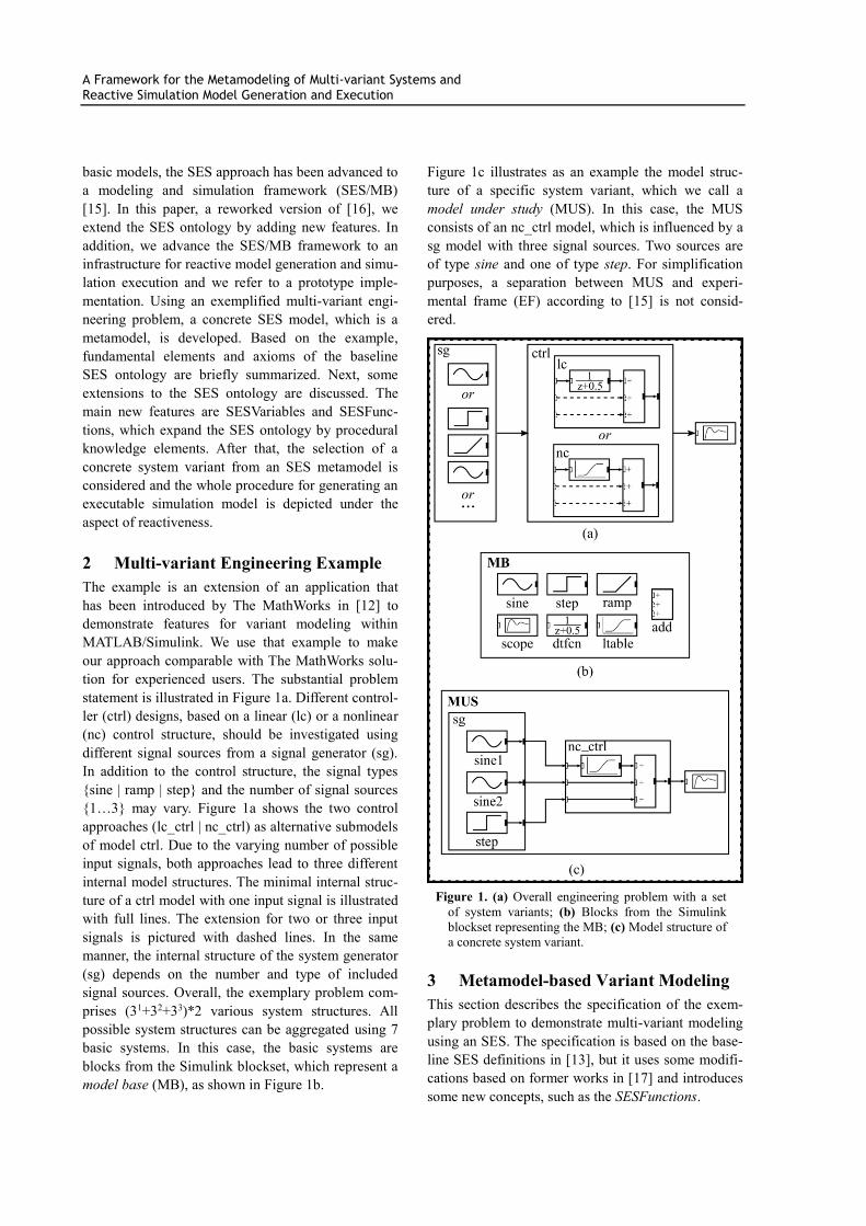
The next decision point is at multi-aspect sgMULT.
According to the number of elements in SESVariable
NSL, the entity s, including its following sub-tree, has
to be replicated three times. During this operation
replicas of s are renamed to comply with the valid
brothers axiom. Moreover, any replica is assigned an
exact value to its attribute type by executing the itera-
tor SESFunction s_fcn with the input argument
NSL={‘sine[1]’,‘sine[2]’,‘step’}. The results of this
operation are the replicated and renamed entities s1,
s2, s3 with their identical sub-trees but an individual
value assignment to their attribute type, as illustrated
in Figure 4. Now, for each entity si the replicated sub-
tree is evaluated. This means that the selection rule
srule_s is evaluated for each node sSPEC. In our
case, it delivers the following selection sine[1], si-
A Framework for the Metamodeling of Multi-variant Systems and Reactive Simulation Model Generation and Execution
ne[2] and step. Remember, the indices of sine denote
the parameter selection for the multiset of attribute
amp.
Figure 4. Part of ‘intermediate PES’ (sub-tree of sg)
during pruning of multi-aspect sgMULT
Next, the parent and child entity of each specializa-
tion relation is combined according to the inheritance
axiom. In this case, only the entity names and attrib-
utes have to be combined, e.g. sine_s1{mb=’sine’;…;
type=’sine[1]’}. Finally, the current coupling rela-
tions, specified at node sgMULT, are determined by
executing the SESFunction call cplg=c_sg(Children,
Parent, NUM). The result is:
sgMULT.cplg={‘sine_s1’, ‘1’, ’sg’, ‘1’;
‘sine_s2’, ‘1’, ’sg’, ‘2’;
‘step’ , ‘1’, ’sg’, ‘3’ }
The sub-tree of entity ctrl in Figure 2 is resolved in a
similar manner during pruning. The resulting cou-
pling relations for entity ctrlDEC are the following:
ctrlDEC.cplg ={‘ctrl’,‘1’,‘ltable_var’,‘1’;
‘ltable_var’,‘1’,‘add’ ,‘1’;
‘add’,‘1’,‘ctrl’ ,‘1’;
‘ctrl’,‘2’,‘add’ ,‘2’;
‘ctrl’,‘3’,‘add’ ,‘3’ }
As mentioned in the beginning, the PES contains all
of the necessary knowledge for building a simulation
model using basic models from the MB. Sometimes,
the PES contains unnecessary attributes due to the
pruning operation, such as type in the entities sine_s1
and sine_s2, which can be neglected when building
the simulation model. Moreover, referring to [15], the
PES can be flattened by restructuring. Then, in our
case the inner nodes sg, sgMULT, ctrl, ctrlDEC are
resolved and all coupling relations are restructured in
the cplg attribute of aspect musDEC.
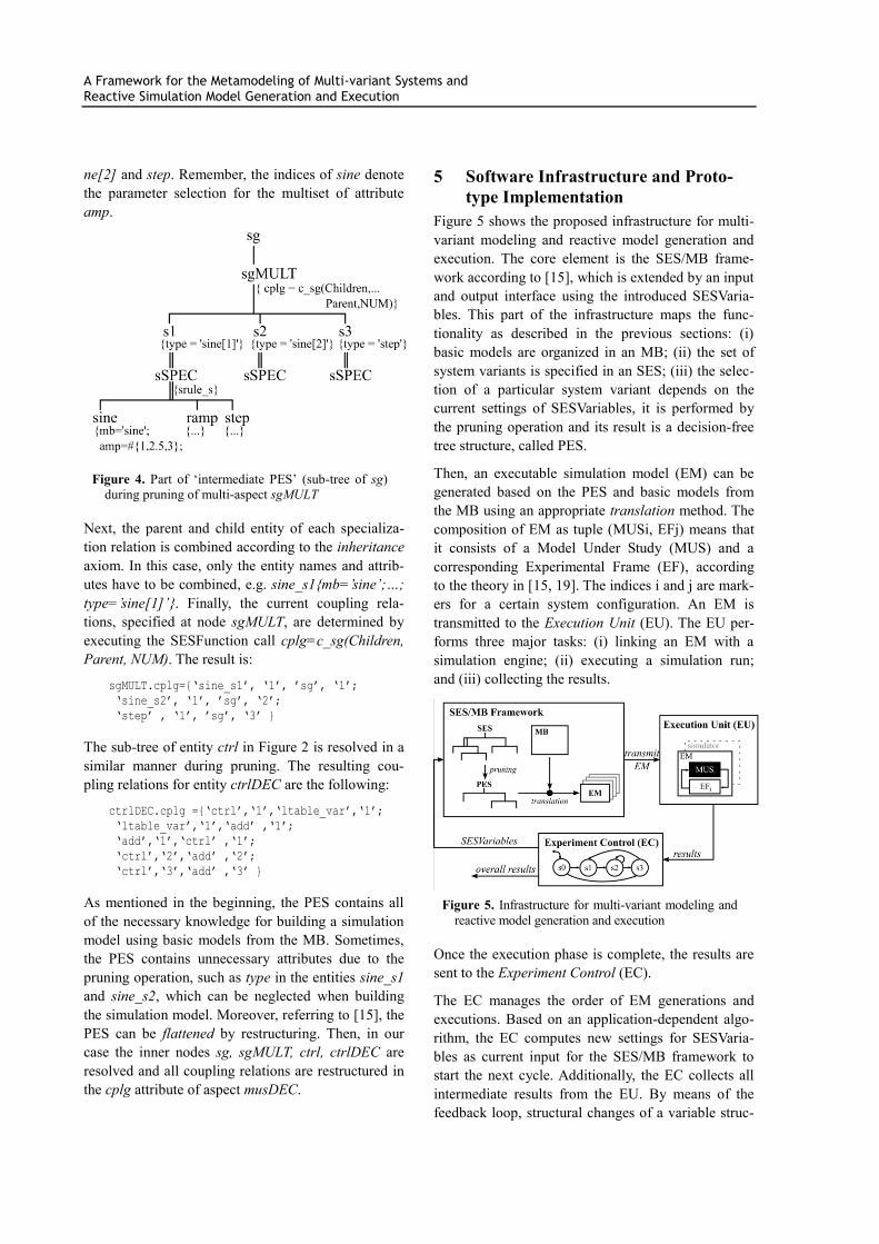
5 Software Infrastructure and Proto-
type Implementation
Figure 5 shows the proposed infrastructure for multi-
variant modeling and reactive model generation and
execution. The core element is the SES/MB frame-
work according to [15], which is extended by an input
and output interface using the introduced SESVaria-
bles. This part of the infrastructure maps the func-
tionality as described in the previous sections: (i)
basic models are organized in an MB; (ii) the set of
system variants is specified in an SES; (iii) the selec-
tion of a particular system variant depends on the
current settings of SESVariables, it is performed by
the pruning operation and its result is a decision-free
tree structure, called PES.
Then, an executable simulation model (EM) can be
generated based on the PES and basic models from
the MB using an appropriate translation method. The
composition of EM as tuple (MUSi, EFj) means that
it consists of a Model Under Study (MUS) and a
corresponding Experimental Frame (EF), according
to the theory in [15, 19]. The indices i and j are mark-
ers for a certain system configuration. An EM is
transmitted to the Execution Unit (EU). The EU per-
forms three major tasks: (i) linking an EM with a
simulation engine; (ii) executing a simulation run;
and (iii) collecting the results.
Figure 5. Infrastructure for multi-variant modeling and
reactive model generation and execution
Once the execution phase is complete, the results are
sent to the Experiment Control (EC).
The EC manages the order of EM generations and
executions. Based on an application-dependent algo-
rithm, the EC computes new settings for SESVaria-
bles as current input for the SES/MB framework to
start the next cycle. Additionally, the EC collects all
intermediate results from the EU. By means of the
feedback loop, structural changes of a variable struc-

A Framework for the Metamodeling of Multi-variant Systems and Reactive Simulation Model Generation and Execution
ture system or experiments with several system con-
figurations can be executed in a reactive manner.
Finally, the EC provides the overall results to the user
or another software component.
For the investigation of multiple system configura-
tions, such as in our introduced engineering example,
it can be useful to generate an EM suite, as illustrated
in Figure 5, and to execute it in a sequential or dis-
tributed manner by the EU.
The proposed infrastructure has been implemented in
the MATLAB/Simulink environment. Thus, a parallel
or distributed execution of EMs by the EU is directly
supported. Basic implementation aspects of the infra-
structure within MATLAB/Simulink and its usage for
solving a specific class of multi-variant problems are
discussed in [20]. A core element of the infrastructure
is the SES toolbox for MATLAB/Simulink, which has
been developed by the Research Group CEA [21, 22].
The toolbox provides a graphical SES editor and
several methods, such as: (i) merging to synthesize
various SESs’; (ii) pruning for deriving a PES; (iii)
flattening for the hierarchy reduction of a PES; (iv)
validity checking of an SES and PES; and (v) transla-
tion scripts or templates to build EM for Simulink or
MATLAB/DEVS [23]. Advanced engineering appli-
cations for deploying the SES toolbox for
MATLAB/Simulink in the field of model-based test-
ing can be found in [20]. Moreover, a new prototype
of the SES toolbox, implemented with Python and
supporting an XML interface, is in development to
open the way for investigating the approach in con-
junction with other simulation environments.
6 Conclusion
Multi-variant modeling and reactive model genera-
tion and execution is an important requirement in
systems and production engineering. This paper pre-
sented a metamodel-based approach using the SES
ontology and introduced an appropriate infrastructure
to solve this requirement. In addition to the baseline
SES definition, the approach uses some new exten-
sions which have been explained step by step based
on an engineering example. The introduced concept
of SESFunctions advances the declarative knowledge
representation through a procedural knowledge speci-
fication. Particularly for the modeling of systems with
a high degree of variability, the SESFunctions support
maintaining a lean SES even for complex problems.
In a next step, this assumption has to be proven by
applying the approach to more complex examples.
The discussed infrastructure, implemented within
MATLAB/Simulink, provides a basis for solving
more complex engineering problems. Currently, it is
used for developing the reactive and structure varia-
ble controls of interacting industrial robots and in the
field of objective fidelity evaluation of flight and
research simulators. Moreover, a new prototype of the
SES toolbox, implemented with Python and support-
ing an XML interface, is in development to open the
way for investigating the approach in conjunction
with other simulation environments.
ACKNOWLEDGMENTS
The authors, T. Pawletta and A. Schmidt, gratefully
acknowledge the grant from the German Science
Foundation DFG (PA 631/2).
References
[1] Capilla R., Bosch J., Kang K.-C. Systems and
Software Variability Management. Springer Pub.,
2013.
[2] Polzer A. et al. Managing complexity and varia-
bility of a model-based embedded software prod-
uct line. Innovations System Software Engineer-
ing. Vol. 8, 35-49, 2012.
[3] Sargardui G., Etxeberria L., Agirre J.A. Variabil-
ity management in testing architectures for em-
bedded control systems. In: The 4th Int. Conf. on
Advances in System Testing and Validation
Lifecycle (VALID 2012). IARIA Press, 73-78,
2012.
[4] Krausz M., Zimmer M., Reuss H.C. OverNight
Testing – The fully automated simulation envi-
ronment for evaluation of car concepts. SNE –
Simulation Notes Europe, Vol. 24(2), 87-94,
2014.
[5] Schmidt A., Pawletta T.: Ein Ontologie-basierter
Modellierungs- und Simulationsansatz am Bei-
spiel der ressourceneffizienten Planung spanen-
der Prozessketten. In: Proc. 15. ASIM Fachtagung
Simulation in Produktion und Logistik, Pader-
born, HNI-Verlagsschriftenreihe Bd. 316, 481-
490, 2013.
[6] Schwatinski T., Pawletta T., Pawletta S. Flexible
Task Oriented Robot Controls Using the System
Entity Structure and Model Base Approach. SNE
– Simulation Notes Europe, Vol. 22(2), 107-114,
2012.

A Framework for the Metamodeling of Multi-variant Systems and Reactive Simulation Model Generation and Execution
[7] Zander J. Model-based Testing of Real-Time Em-
bedded Systems in the Automotive Domain. PhD
Thesis, TU Berlin, 2008.
[8] Beuche D. Modeling and building software prod-
uct lines with pure::variants. In: Proc. 12th Int.
Software Product Line Conf., IEEE Comp. Soc.,
358-358, 2008.
[9] Barros, F.J. The dynamic structure discrete event
system specification formalism. Transactions of
the SCS International, No.1, 35-46, 1996.
[10] Pawletta T., Lampe B., Pawletta S., Drewelow, W.
A DEVS-based approach for modeling and simu-
lation of hybrid variable structure systems. In:
Modeling, Anlysis, and Design of Hybrid Sys-
tems, Lecture Notes in Control and Information
Sciences 279, Springer Pub. , 107-129, 2002.
[11] Haber A. et al. First-class variability modeling in
MATLAB/Simulink. In: Proc. of the 7th Int. Work-
shop on Variability Modelling of Software-
intensive Systems. ACM Press, 11-18, 2013.
[12] The MathWorks. Variant management.
http://de.mathworks.com/help/simulink/ug/variant
-management.html, Date of reading 12-Nov.
2015.
[13] Zeigler B.P., Hammonds P.E. Modeling and Simu-
lation-Based Data Engineering. Academic Press,
2007.
[14] Zeigler B.P., Sarjoughian H.S., Guide to Model-
ing and Simulation of Systems of Systems. Spring-
er Pub., 2012.
[15] Zeigler B.P., Prähofer H., Kim T.G., Theory of
Modeling and Simulation. Academic Press, 2000.
[16] Pawletta T., Schmidt A., Zeigler B.P, Durak U.
Extended Variability Modeling Using System En-
tity Structure Ontology within MATLAB/ Sim-
ulink. In: Proc. SprigSim-ANSS 2016, Pasade-
na/CA, USA, 62-69, 2016.
[17] Rozenblit, J.W., Zeigler, B.P. Representing and
constructing system specifications using the sys-
tem entity structure concepts. In: Proc. of the
1993 Winter Simulation Conf., 604-611, 1993.
[18] Pidcock W., Uschold M. What are the differences
between a vocabulary, a taxonomy, a thesaurus,
an ontology, and a meta-model? In: The Web
Graph Database, http://infogrid.org/trac/wiki/
Reference/PidcockArticle, Date of reading 7-July
2016.
[19] Traoré M., Muzy A. Capturing the dual relation-
ship between simulation models and their context.
Simulation Modelling Practice and Theory, No. 2,
126-142, 2006.
[20] Schmidt A., Durak U., Pawletta T. Model-based
testing methodology using system entity structures
for MATLAB/Simulink models. Simulation:
Transactions of SCS Int., Sage Pub., DOI:
10.1177/0037549716656791, 18 pp., 2016.
[21] Pawletta T., Pascheka D., Schmidt A., Pawletta S.
Ontology-assisted system modeling and simula-
tion within MATLAB/Simulink. SNE – Simulation
Notes Europe, Vol. 24(2), 59-68, 2014.
[22] Pawletta T., Schmidt A., Pascheka D. SES
Toolbox for MATLAB/Simulink. https://www.mb.
hs-wismar.de/cea/SES_Tbx/, Date of reading 12-
Nov. 2015.
[23] Deatcu C., Schwatinski T., Pawletta T. DEVS
Toolbox for MATLAB. https://www.mb.hs-
wismar.de/cea/SES_Tbx/, Date of reading 12-
Nov. 2015.


![AMVG: Adaptive Malware Variant Generation Framework ......perturbation applications similarly as in [6]. C. Genetic algorithm for malware variant generations GA has been used widely](https://img.pdfslide.us/doc/110x75/600c68fbf68b6b152e285354/amvg-adaptive-malware-variant-generation-framework-perturbation-applications.jpg)