Embed Size (px)
Citation preview

ÉCOLE POLYTECHNIQUE FÉDÉRALE DE LAUSANNE
IC Faculty - School of Computer Science
Master Project
A Framework for Automatic Generationof OSRA-compliant Applications in BIP
By
ALEXANDRE SIKIARIDIS
Supervised By
PR. JEAN-YVES LE BOUDEC
Co-Supervised By
DR. SIMON BLIUDZE
DR. ANTON IVANOV
JANUARY 2017

ABSTRACT
This Master Project designed and implemented a framework facilitating the design of OSRA-compliant BIP systems.Given a set of application components developed in BIP, the framework automates the
generation of a BIP system handling safe interactions between the components. The primary usefor such a system is simulation, verification and testing.The framework was successfully used to implement a BIP software model for the CubETHnanosatellite.
i

TABLE OF CONTENTS
Page
List of Figures v
1 Introduction 1
2 Overview of OSRA 32.1 Overview . . . . . . . . . . . . . . . . . . . . . . . . . . . . . . . . . . . . . . . . . . . . 3
2.2 Concept . . . . . . . . . . . . . . . . . . . . . . . . . . . . . . . . . . . . . . . . . . . . . 3
2.3 Reference Development Process . . . . . . . . . . . . . . . . . . . . . . . . . . . . . . . 4
2.4 Reference Architecture . . . . . . . . . . . . . . . . . . . . . . . . . . . . . . . . . . . . 6
2.4.1 Component Layer . . . . . . . . . . . . . . . . . . . . . . . . . . . . . . . . . . 6
2.4.2 Interaction Layer . . . . . . . . . . . . . . . . . . . . . . . . . . . . . . . . . . . 7
2.4.3 Execution Layer . . . . . . . . . . . . . . . . . . . . . . . . . . . . . . . . . . . 7
2.4.4 Interface Specification . . . . . . . . . . . . . . . . . . . . . . . . . . . . . . . . 8
3 Overview of BIP 113.1 Atoms . . . . . . . . . . . . . . . . . . . . . . . . . . . . . . . . . . . . . . . . . . . . . . 11
3.2 Compounds . . . . . . . . . . . . . . . . . . . . . . . . . . . . . . . . . . . . . . . . . . . 12
3.3 BIP Versions . . . . . . . . . . . . . . . . . . . . . . . . . . . . . . . . . . . . . . . . . . 13
4 Simulating OSRA Components in BIP 154.1 Motivation and Goals . . . . . . . . . . . . . . . . . . . . . . . . . . . . . . . . . . . . . 15
4.2 Component Layer . . . . . . . . . . . . . . . . . . . . . . . . . . . . . . . . . . . . . . . 16
4.2.1 Concepts . . . . . . . . . . . . . . . . . . . . . . . . . . . . . . . . . . . . . . . . 16
4.2.2 Additional Constraints when Implementing a COMPONENT . . . . . . . . . 21
4.2.3 Properties Definition . . . . . . . . . . . . . . . . . . . . . . . . . . . . . . . . . 22
4.3 Interaction Layer . . . . . . . . . . . . . . . . . . . . . . . . . . . . . . . . . . . . . . . 23
4.3.1 The Computational Model . . . . . . . . . . . . . . . . . . . . . . . . . . . . . 23
4.3.2 Activity Groups . . . . . . . . . . . . . . . . . . . . . . . . . . . . . . . . . . . . 24
4.3.3 Containers . . . . . . . . . . . . . . . . . . . . . . . . . . . . . . . . . . . . . . . 24
4.3.4 Thread . . . . . . . . . . . . . . . . . . . . . . . . . . . . . . . . . . . . . . . . . 29
iii

TABLE OF CONTENTS
4.3.5 Activator . . . . . . . . . . . . . . . . . . . . . . . . . . . . . . . . . . . . . . . . 29
4.3.6 Locks . . . . . . . . . . . . . . . . . . . . . . . . . . . . . . . . . . . . . . . . . . 30
4.3.7 HkIntermediary . . . . . . . . . . . . . . . . . . . . . . . . . . . . . . . . . . . 30
4.4 Execution Layer . . . . . . . . . . . . . . . . . . . . . . . . . . . . . . . . . . . . . . . . 30
4.4.1 LifeCycle . . . . . . . . . . . . . . . . . . . . . . . . . . . . . . . . . . . . . . . . 30
4.4.2 Scheduler . . . . . . . . . . . . . . . . . . . . . . . . . . . . . . . . . . . . . . . 31
4.4.3 Tasking . . . . . . . . . . . . . . . . . . . . . . . . . . . . . . . . . . . . . . . . . 32
4.4.4 Reporting . . . . . . . . . . . . . . . . . . . . . . . . . . . . . . . . . . . . . . . 34
4.4.5 Device Access . . . . . . . . . . . . . . . . . . . . . . . . . . . . . . . . . . . . . 35
4.4.6 Unimplemented services . . . . . . . . . . . . . . . . . . . . . . . . . . . . . . 36
5 CubETH Case Study 375.1 CubETH . . . . . . . . . . . . . . . . . . . . . . . . . . . . . . . . . . . . . . . . . . . . . 37
5.2 BIP Simulation . . . . . . . . . . . . . . . . . . . . . . . . . . . . . . . . . . . . . . . . 38
5.2.1 Service 13 . . . . . . . . . . . . . . . . . . . . . . . . . . . . . . . . . . . . . . . 38
5.2.2 Service 15_8 . . . . . . . . . . . . . . . . . . . . . . . . . . . . . . . . . . . . . . 40
5.2.3 Flash Memory . . . . . . . . . . . . . . . . . . . . . . . . . . . . . . . . . . . . . 42
5.2.4 I2C_Sat Bus . . . . . . . . . . . . . . . . . . . . . . . . . . . . . . . . . . . . . . 43
5.2.5 Housekeeping . . . . . . . . . . . . . . . . . . . . . . . . . . . . . . . . . . . . . 43
5.2.6 Non-functional Properties . . . . . . . . . . . . . . . . . . . . . . . . . . . . . 45
5.2.7 Connecting the System . . . . . . . . . . . . . . . . . . . . . . . . . . . . . . . 46
5.2.8 Output of a Simulation . . . . . . . . . . . . . . . . . . . . . . . . . . . . . . . 46
6 Future Work 51
7 Conclusion 53
8 Acknowledgements 55
A Interaction Layer Generation 57A.1 Scala . . . . . . . . . . . . . . . . . . . . . . . . . . . . . . . . . . . . . . . . . . . . . . . 57
A.1.1 The ParserCombinator Library . . . . . . . . . . . . . . . . . . . . . . . . . . 57
A.2 Interaction Layer Generation . . . . . . . . . . . . . . . . . . . . . . . . . . . . . . . . 58
A.2.1 Parsing . . . . . . . . . . . . . . . . . . . . . . . . . . . . . . . . . . . . . . . . . 58
A.2.2 Building Components . . . . . . . . . . . . . . . . . . . . . . . . . . . . . . . . 59
A.2.3 Building the System Compound . . . . . . . . . . . . . . . . . . . . . . . . . . 59
A.2.4 Writing to File . . . . . . . . . . . . . . . . . . . . . . . . . . . . . . . . . . . . 59
A.3 Definition of System Properties . . . . . . . . . . . . . . . . . . . . . . . . . . . . . . . 60
Bibliography 63
iv

LIST OF FIGURES
FIGURE Page
2.1 Containers . . . . . . . . . . . . . . . . . . . . . . . . . . . . . . . . . . . . . . . . . . . . . 5
2.2 OSRA Three-Layer Architecture . . . . . . . . . . . . . . . . . . . . . . . . . . . . . . . . 6
2.3 OSI primitives patterns . . . . . . . . . . . . . . . . . . . . . . . . . . . . . . . . . . . . . . 9
3.1 Diagram of an Atom . . . . . . . . . . . . . . . . . . . . . . . . . . . . . . . . . . . . . . . . 13
4.1 Models of simple COMPONENTS . . . . . . . . . . . . . . . . . . . . . . . . . . . . . . . . . 17
4.2 activity types . . . . . . . . . . . . . . . . . . . . . . . . . . . . . . . . . . . . . . . . . . . . 20
4.3 A diagram of the generated Container for the S15 COMPONENT. . . . . . . . . . . . . . 25
4.4 Diagram of the generated Container for the simplified I2C COMPONENT . . . . . . . . 28
4.5 Thread component . . . . . . . . . . . . . . . . . . . . . . . . . . . . . . . . . . . . . . . . . 29
4.6 Basic Activator component . . . . . . . . . . . . . . . . . . . . . . . . . . . . . . . . . . . . 29
4.7 Lock Component . . . . . . . . . . . . . . . . . . . . . . . . . . . . . . . . . . . . . . . . . . 29
4.8 A diagram of the implemented LifeCycle service . . . . . . . . . . . . . . . . . . . . . . . 31
4.9 Diagram of the Execution Layer’s Scheduler service . . . . . . . . . . . . . . . . . . . . 33
4.10 Diagram of the Execution Layer’s Tasking service . . . . . . . . . . . . . . . . . . . . . . 34
4.11 Diagram of the Execution Layer’s Reporting service . . . . . . . . . . . . . . . . . . . . 35
4.12 A diagram of the implemented Device Access service . . . . . . . . . . . . . . . . . . . . 36
5.1 Connections diagram for the CubETH Model . . . . . . . . . . . . . . . . . . . . . . . . . 39
5.2 Diagram of the S13 Component in the CubETH Model . . . . . . . . . . . . . . . . . . . 40
5.3 Diagram of the modified S13 Component . . . . . . . . . . . . . . . . . . . . . . . . . . . 40
5.4 Diagram of the S15 Component in the CubETH Model . . . . . . . . . . . . . . . . . . . 41
5.5 Diagram of the modified S15 Component . . . . . . . . . . . . . . . . . . . . . . . . . . . 41
5.6 Diagram of the Flash Memory Component in the CubETH Model . . . . . . . . . . . . 42
5.7 Diagram of the modified Flash Memory Component . . . . . . . . . . . . . . . . . . . . . 42
5.8 Diagram of the I2C Sat Component in the CubETH Model . . . . . . . . . . . . . . . . 44
5.9 Diagram of the modified I2C Sat Component . . . . . . . . . . . . . . . . . . . . . . . . . 44
5.10 Diagram of the Internal Housekeeping Component in the CubETH Model . . . . . . . 45
5.11 Diagram of the modified Housekeeping Component . . . . . . . . . . . . . . . . . . . . . 45
v

LIST OF FIGURES
5.12 Summary of Connector Blocks used in the diagram for the complete system . . . . . . 47
5.13 Diagram of the complete generated system, with Component Groups and Layers
indicated by coloured separations . . . . . . . . . . . . . . . . . . . . . . . . . . . . . . . . 48
5.14 Diagram of the complete generated system . . . . . . . . . . . . . . . . . . . . . . . . . . 49
vi

CH
AP
TE
R
1INTRODUCTION
The development of on-board software for satellite components introduces many difficulties
which engineers are tasked with solving. They range from project management issues -
such as reducing recurring costs and shortening software development time -, to downright
engineering matters - such as maintaining product quality, or ensuring correct integration within
larger systems.
The European Space Agency’s (ESA) On-board Software Reference Architecture (OSRA)
[10], is a bid to answer those questions. By defining a reference development process, and a
reference architecture, OSRA standardises spacecraft on-board software development by relying
on Component Based Software Engineering principles. This can simplify system integration and
sub-contracting of component implementations, as well as reduce verification and validation
efforts.
OSRA’s reliance on CBSE makes it well suited to an implementation in BIP - a framework
for rigorous system design based on similar principles. This project’s goal is to develop a frame-
work facilitating the design of OSRA-compliant BIP systems, which can be used for simulation,
verification and testing.
This report first describes key elements of the OSRA, and basics of the BIP language. We
then cover the framework itself, explaining implementation choices and design constraints,
before describing a case study in the context of which we adapted a BIP model of the CubETH
nanosatellite to this framework. We conclude with recommendation as to possible improvements
to the framework in future work.
1


CH
AP
TE
R
2OVERVIEW OF OSRA
This chapter gives a high-level overview of the the European Space Agency’s (ESA) On-
board Software Reference Architecture (OSRA), and details more particularly the parts
that were instrumental for the system described in this report.
2.1 Overview
The OSRA was conceived by ESA and its partners, as a response to growing complexity and costs
in spacecraft on-board software development [4, p. 4]. As a reference architecture, it describes a
general design for the implementation of typical spacecraft software, as well as offers guidelines
for the development of such a system.
It was written with the goal of answering a clear set of requirements [10, p. 15]. Those include
matters such as maintenance of product quality, or the reduction of development time, recurring
costs, and verification and validation efforts. To achieve those goals, it relies on the principles of
Component Based Software Engineering (CBSE) and Model Driven Architecture (MDA) to guide
software design. These choices make OSRA particularly well suited to an implementation in BIP,
which leverages the same principles.
We first describe the general design of the OSRA, before detailing elements selected for
implementation in this project.
2.2 Concept
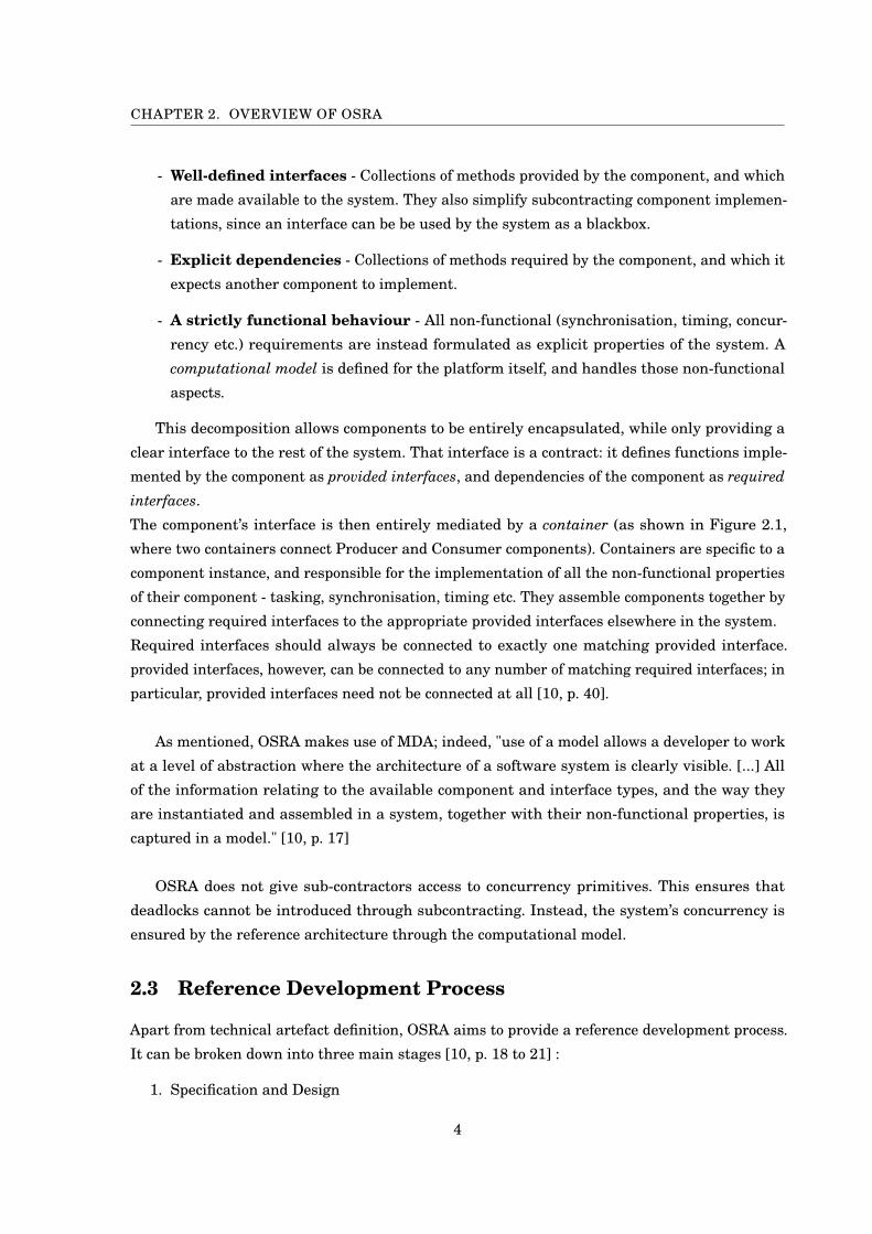
OSRA applications are decomposed into entities called components [10, p. 16]. A component has:
3
CHAPTER 2. OVERVIEW OF OSRA
- Well-defined interfaces - Collections of methods provided by the component, and which
are made available to the system. They also simplify subcontracting component implemen-
tations, since an interface can be be used by the system as a blackbox.
- Explicit dependencies - Collections of methods required by the component, and which it
expects another component to implement.
- A strictly functional behaviour - All non-functional (synchronisation, timing, concur-
rency etc.) requirements are instead formulated as explicit properties of the system. A
computational model is defined for the platform itself, and handles those non-functional
aspects.
This decomposition allows components to be entirely encapsulated, while only providing a
clear interface to the rest of the system. That interface is a contract: it defines functions imple-
mented by the component as provided interfaces, and dependencies of the component as required
interfaces.
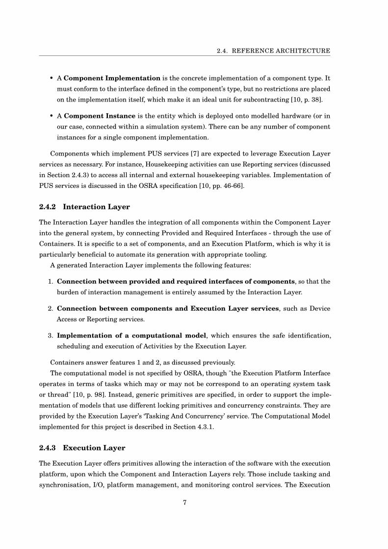
The component’s interface is then entirely mediated by a container (as shown in Figure 2.1,
where two containers connect Producer and Consumer components). Containers are specific to a
component instance, and responsible for the implementation of all the non-functional properties
of their component - tasking, synchronisation, timing etc. They assemble components together by
connecting required interfaces to the appropriate provided interfaces elsewhere in the system.
Required interfaces should always be connected to exactly one matching provided interface.
provided interfaces, however, can be connected to any number of matching required interfaces; in
particular, provided interfaces need not be connected at all [10, p. 40].
As mentioned, OSRA makes use of MDA; indeed, "use of a model allows a developer to work
at a level of abstraction where the architecture of a software system is clearly visible. [...] All
of the information relating to the available component and interface types, and the way they
are instantiated and assembled in a system, together with their non-functional properties, is
captured in a model." [10, p. 17]
OSRA does not give sub-contractors access to concurrency primitives. This ensures that
deadlocks cannot be introduced through subcontracting. Instead, the system’s concurrency is
ensured by the reference architecture through the computational model.
2.3 Reference Development Process
Apart from technical artefact definition, OSRA aims to provide a reference development process.
It can be broken down into three main stages [10, p. 18 to 21] :
1. Specification and Design
4
2.3. REFERENCE DEVELOPMENT PROCESS
Figure 2.1: Containers for Producer and Consumer Components mediate their interfaces andallow the Producer to call the Consumer’s ‘consume(c)’ function.
2. Software Construction
3. Software System Integration
One key advantage of this process is to distribute Verification and Validation efforts across all
three steps.
Specification and Design begins with analysing system requirements, and potentially
selecting elements of reuse - such as execution environments, or application components - from
previous missions. Designs of the software are made in terms of Components, and even the
earliest iterations can capture the structural aspects of the final system; resource and timing
constraints, execution environment elements etc. This allows early analyses of the system to be
conducted, and adaptations to the specification and design can be made early when they are less
costly to resolve, and with reduced validation efforts.
Software Construction involves implementing the functional aspects of the Components.
The contractual link between a Component’s functionality and its interface assists in distributing
implementation work, within a team or to subcontractors, and pushes non-functional issues to
the later stage of software integration.
Software System Integration finally is the step when the software system design in the
specification stage is populated with the implementations provided from the construction stage.
5

CHAPTER 2. OVERVIEW OF OSRA
Figure 2.2: OSRA Three-Layer Architecture
Because the interfaces and broad behaviour of each Component is known, it is possible to inte-
grate a system with only a subset of the Component Implementations ready, making an early
integration possible - further simplifying the validation effort.
OSRA also specifies that, "since the functional and non-functional requirements on the code
which is responsible for managing and assembling components [...] are fully captured by the
model, it is possible [...] to use appropriate tooling to automatically generate all of this code."
This greatly cuts down the integration time (particularly when iterating over a system), and
developing such tooling was a major part of the project described in this report (see Chapter ??).
2.4 Reference Architecture
The reference structure in OSRA is a three-layered architecture, as depicted in Figure 2.2 (see
also [10, p. 23-24]).
2.4.1 Component Layer
The Component Layer is where the application software is described, in the form of Components.
It is independent of the Execution Platform and the Computational Model - which defines the
Tasking model and other non-functional properties of the system. In essence, the Component
Layer is isolated from all platform concerns, so that software developers and suppliers may
operate within it exclusively.
The OSRA distinguishes different specification degrees for components:
• A Component Type represent the contractual specification of the component. It provides
a list of required and provided interfaces.
6
2.4. REFERENCE ARCHITECTURE
• A Component Implementation is the concrete implementation of a component type. It
must conform to the interface defined in the component’s type, but no restrictions are placed
on the implementation itself, which make it an ideal unit for subcontracting [10, p. 38].
• A Component Instance is the entity which is deployed onto modelled hardware (or in
our case, connected within a simulation system). There can be any number of component
instances for a single component implementation.
Components which implement PUS services [7] are expected to leverage Execution Layer
services as necessary. For instance, Housekeeping activities can use Reporting services (discussed
in Section 2.4.3) to access all internal and external housekeeping variables. Implementation of
PUS services is discussed in the OSRA specification [10, pp. 46-66].
2.4.2 Interaction Layer
The Interaction Layer handles the integration of all components within the Component Layer
into the general system, by connecting Provided and Required Interfaces - through the use of
Containers. It is specific to a set of components, and an Execution Platform, which is why it is
particularly beneficial to automate its generation with appropriate tooling.
A generated Interaction Layer implements the following features:
1. Connection between provided and required interfaces of components, so that the
burden of interaction management is entirely assumed by the Interaction Layer.
2. Connection between components and Execution Layer services, such as Device
Access or Reporting services.
3. Implementation of a computational model, which ensures the safe identification,
scheduling and execution of Activities by the Execution Layer.
Containers answer features 1 and 2, as discussed previously.
The computational model is not specified by OSRA, though "the Execution Platform Interface
operates in terms of tasks which may or may not be correspond to an operating system task
or thread" [10, p. 98]. Instead, generic primitives are specified, in order to support the imple-
mentation of models that use different locking primitives and concurrency constraints. They are
provided by the Execution Layer’s ‘Tasking And Concurrency’ service. The Computational Model
implemented for this project is described in Section 4.3.1.
2.4.3 Execution Layer
The Execution Layer offers primitives allowing the interaction of the software with the execution
platform, upon which the Component and Interaction Layers rely. Those include tasking and
synchronisation, I/O, platform management, and monitoring control services. The Execution
7

CHAPTER 2. OVERVIEW OF OSRA
Layer should be adapted to the underlying hardware, and its re-usability is therefore dependent
on appropriate configuration.
When Components need to use Execution Layer services, they interact with the Execution
Layer as if the services were themselves implemented at the Component Layer level ; those are
referred to in OSRA as Pseudo-Components [10, p. 46]. "Components interface with what appears
to be normal components [... though] this access is actually carried out through the Interaction
Layer".
The Execution Services that were used in the context of this project are listed here [10,
pp. 93-99].
• the Tasking And Concurrency service, which offers primitives for the management of
tasks and locks. Those include:
Task_execute.indication,
Task_execute.response ,
Resource_lockAcquire.request,
Resource_lockAcquire.confirmation,
Resource_lockRelease.request, and
Resource_lockRelease.confirmation
• the LifeCycle Management service, which includes primitives for system initialisation
and restart, and reporting of non-fatal errors. LifeCycle primitives that were implemented
for this project include:
Platform_init.indication
• the Reporting service, which collects reports of attribute data across the system.
Reporting primitives that were implemented for this project include:
ParameterReporting_getParameters.indication, and
ParameterReporting_getParameters.response
• the Device Access service, which uses CCSDS Spacecraft Onboard Interface Services
(SOIS), and Device Virtualisation Service (DVS) primitives to connect service users to
onboard devices. Device Access primitives that were implemented for this project include:
DVS_acquire.request, and
DVS_acquire.confirmation
2.4.4 Interface Specification
For the naming scheme of interfaces, OSRA uses ISO Open Systems Interconnected (OSI) service
primitives. [10, p. 25].
OSI primitives place architectural elements in the roles of service providers or users. Depending
8
2.4. REFERENCE ARCHITECTURE
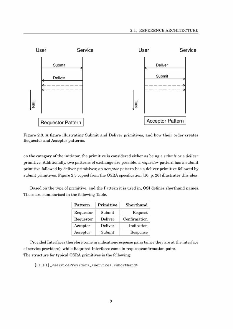
Figure 2.3: A figure illustrating Submit and Deliver primitives, and how their order createsRequestor and Acceptor patterns.
on the category of the initiator, the primitive is considered either as being a submit or a deliver
primitive. Additionally, two patterns of exchange are possible: a requestor pattern has a submit
primitive followed by deliver primitives; an acceptor pattern has a deliver primitive followed by
submit primitives. Figure 2.3 copied from the OSRA specification [10, p. 26] illustrates this idea.
Based on the type of primitive, and the Pattern it is used in, OSI defines shorthand names.
Those are summarised in the following Table.
Pattern Primitive Shorthand
Requestor Submit Request
Requestor Deliver Confirmation
Acceptor Deliver Indication
Acceptor Submit Response
Provided Interfaces therefore come in indication/response pairs (since they are at the interface
of service providers), while Required Interfaces come in request/confirmation pairs.
The structure for typical OSRA primitives is the following:
{RI,PI}_<serviceProvider>_<service>.<shorthand>
9


CH
AP
TE
R
3OVERVIEW OF BIP
B IP is a general framework for rigorous system design. It provides both the BIP language
- a notation for expressing complex systems in terms of atomic components and their
interaction - as well as a tool-set for verification and validation purposes [2] [11].
BIP stands for "Behaviour - Interaction - Priority". Indeed, BIP systems are described in
three layers:
1. A behaviour layer, which describes individual components as Petri Nets, and supports
implementation in C of functions and data.
2. An interaction layer, which describes the interactions between individual components.
3. A priority layer, which expresses scheduling policies between connections.
BIP components can be hierarchically assembled into compound components.
The BIP tool-set provides a compiler which generates C implementations of systems described
in the BIP language. A dedicated engine can then simulate the execution of the model, selecting
among enabled component interactions or interacting with the user to make the choice.
A detailed tutorial can be found at [1].
3.1 Atoms
An atomic component in BIP is called an atom. It is defined in terms of data parameters, places,
transitions and ports.
Data parameters are variables held by the atom. They rely on C data types, and can be used
to transfer information over connections.
11

CHAPTER 3. OVERVIEW OF BIP
Places - or states - are endpoints to transitions, and represent the state of the atom. Each
place has a name which must be unique to the atom.
If no transition exits a place, that place represents a deadlock - a state from which the atom can
no longer progress.
Transitions represent the atom’s action. Through transitions, an atom can move between
states and execute pieces of code.
A transition has two endpoints: a start and a finish state (possibly the same). It can also have a
guard - a boolean expression which blocks the transition if it evaluates to false -, as well as C
code to execute upon being activated.
An initial transition must always be provided, and is executed upon the atom’s initialisation. It
has no starting place (only a finish place) and no guard can be enforced on it, but a piece of code
can be associated to it - typically for data initialisation.
Ports are labels on transitions. They have a type, can hold data parameters, and can be
assigned a priority. A port is enabled if the transition it labels is available at the given time and
no other available transition has a higher priority.
Ports can be exported; they can then be connected to other components. This also has the effect of
making their data parameters visible to the connected ports.
Port types can be defined by the developer. They have a name, and specify the types of parame-
ters a port can hold.
Priorities are partial orderings on ports of an atom or compound. Based on that ordering,
available transitions can be prevented from firing if another of higher priority is available too.
Example
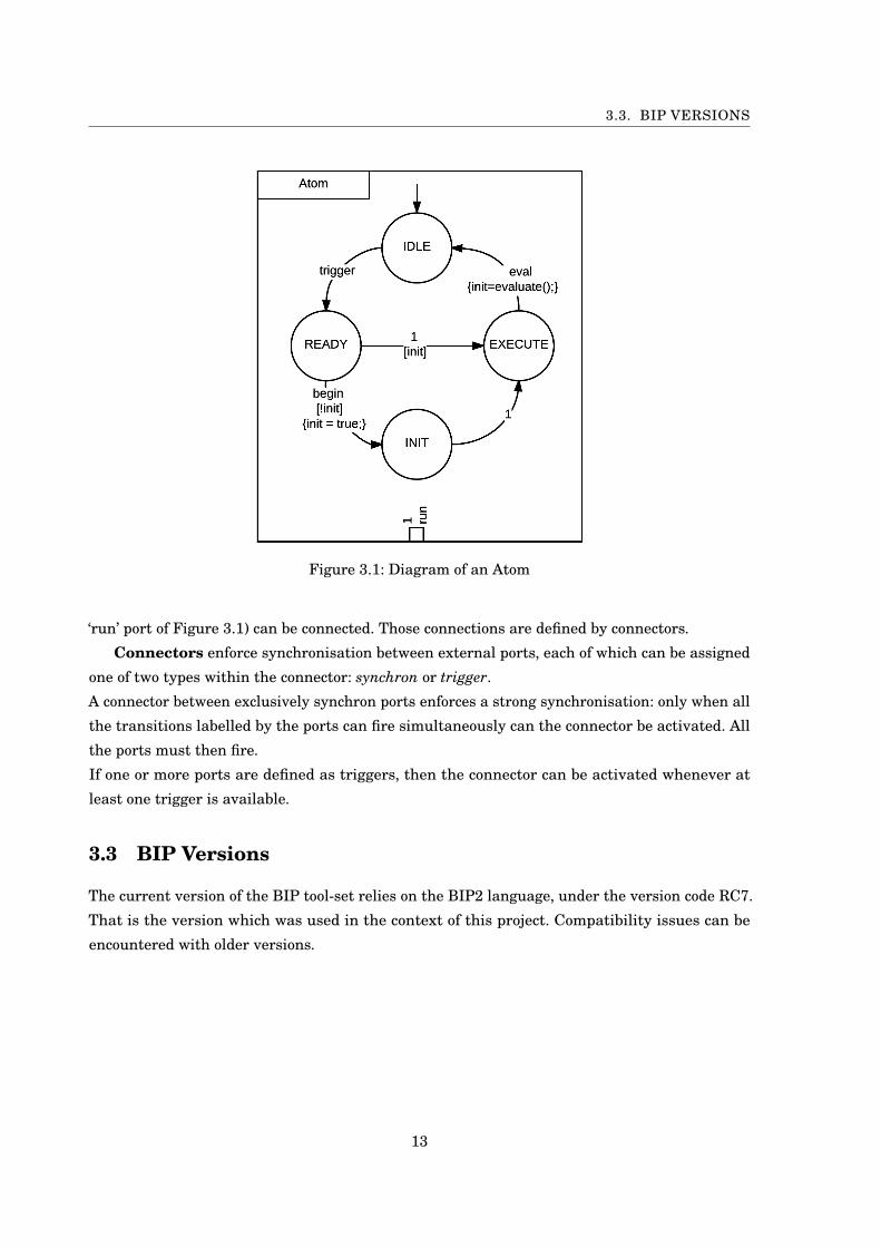
Figure 3.1 represents an atom. It has four places: IDLE, READY, INIT and EXECUTE. It has
four ports - only the ‘run’ port is exported (as represented by the white square at the atom’s
border) -, and five transitions - two of them being labelled with the same port.
The initial transition sends the atom to the INIT state, from which only the ‘trigger’ transition
can be activated, moving it to the READY state. There, it has a choice to make between firing
ports ‘begin’ or ‘run’; however, the ‘run’ port is guarded by the ‘init’ variable, which we can assume
is initialised to false (though this is not expressed in the diagram). Only the ’begin’ port can
therefore be fired, followed by the ‘run’ port from INIT to EXECUTE. Finally, the ‘eval’ port is
fired, sending the atom back to the IDLE state, and setting the value of the init variable with the
return value of the ‘evaluate()’ method call.
3.2 Compounds
Compounds combine atoms and other compounds into a larger system.
Within a compound, instances of components are declared, and their external ports (such as the
12
3.3. BIP VERSIONS
Figure 3.1: Diagram of an Atom
‘run’ port of Figure 3.1) can be connected. Those connections are defined by connectors.
Connectors enforce synchronisation between external ports, each of which can be assigned
one of two types within the connector: synchron or trigger.
A connector between exclusively synchron ports enforces a strong synchronisation: only when all
the transitions labelled by the ports can fire simultaneously can the connector be activated. All
the ports must then fire.
If one or more ports are defined as triggers, then the connector can be activated whenever at
least one trigger is available.
3.3 BIP Versions
The current version of the BIP tool-set relies on the BIP2 language, under the version code RC7.
That is the version which was used in the context of this project. Compatibility issues can be
encountered with older versions.
13

CH
AP
TE
R
4SIMULATING OSRA COMPONENTS IN BIP
This chapter describes a concrete design architecture implementing a simulation frame-
work in BIP for COMPONENTS with an OSRA interface. We first describe motivation and
goals for the system, and then delve deeper into each part of the architecture, and in par-
ticular the details regarding how OSRA specifications were interpreted to fit the implementation.
Throughout this chapter, we use SMALLCAPS FONTS when designating OSRA components, in
order to differentiate them from BIP components.
4.1 Motivation and Goals
As we mentioned in Section 2.1, the OSRA was developed in the hope of alleviating some
the challenges faced by space software development, through the standardisation of concepts.
The most prominent of these is the use of Component-Based Software Engineering (CBSE),
which means BIP is a very natural implementation framework. On top of that, BIP makes code
generation from the model definitions automatic, and provides support for the verification and
validation process through its tool-set.
The goal of the framework described here is to facilitate the design of OSRA-compliant BIP
systems by providing a parametrised implementation of the Execution Layer, as well as automated
generation of the Interaction Layer, based on a set of application components independently
developed in BIP. The primary use of such systems is for simulation, verification and testing.
However, the automatic generation of C++ code provided by the BIP framework also allows
the deployment of such systems on target platforms, for which C++11 compilers are available.
Given a set of COMPONENTS and properties for the system, as well as an implementation of an
Execution Layer, it is possible to generate an Interaction Layer connecting the COMPONENTS
into a valid, concurrent system. The system can then be simulated. A possible next step is to use
15

CHAPTER 4. SIMULATING OSRA COMPONENTS IN BIP
this framework for early validation of externally developed COMPONENTS, by wrapping them
inside corresponding BIP ones.
The overall design follows the OSRA’s three-layered architecture: Component Layer, Inter-
action Layer, and Execution Layer. We describe each layer in turn, and how they interact with
one-another.
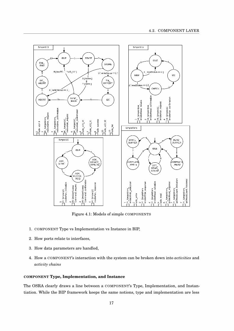
Throughout this chapter, we will use the following four COMPONENTS for our examples. They
are a simplified subset of the COMPONENTS presented in Chapter 5.
• a Memory COMPONENT. It provides read and write methods, through two loops around the
‘IDLE’ state. It also holds an ‘S15Count’ variable, which is made available with a provided
port.
• an I2C COMPONENT. It handles data exchanges over the I2C bus between satellite subsys-
tems, through a loop which receives requests and contacts the appropriate onboard device
using an Execution Layer service.
• a service 15 (s15) COMPONENT, which downlinks data present in the Flash Memory. It
does so by reading the data from memory (calling the Memory’s ‘Read’ method), and sending
it to the COM subsystem using the I2C bus (using the I2C’s ‘Ask’ method). Read failures
abort the service.
• a service 13 (s13) COMPONENT, which implements the large uplink service. It receives
data over the I2C bus (using the I2C’s ‘Ask’ method), and writes it to the Flash Memory
Figure 4.1 shows a graphical diagram of each. For readability, transitions were labelled with
numbers, and the associated ports declared at the bottom of the diagram.
4.2 Component Layer
The Component Layer is where individual software Components are described. It is a set of BIP
atoms and compounds, exclusively implementing their functional behaviour; properties may then
be added, describing the non-functional aspects of the software. For instance, lists of protected
activities (defined in Section 4.2.1) and housekeeping variables have to be provided separately.
We first describe how the various concepts important to the Component Layer were imple-
mented, before discussing the implementation of components themselves. Some concepts are not
part of the OSRA specification, but were introduced for a variety of reasons which we discuss on
a case-by-case basis.
4.2.1 Concepts
This section describes several concepts which underline the relation between OSRA COMPONENTS
and their BIP implementation :
16
4.2. COMPONENT LAYER
Figure 4.1: Models of simple COMPONENTS
1. COMPONENT Type vs Implementation vs Instance in BIP,
2. How ports relate to interfaces,
3. How data parameters are handled,
4. How a COMPONENT’s interaction with the system can be broken down into activities and
activity chains
COMPONENT Type, Implementation, and Instance
The OSRA clearly draws a line between a COMPONENT’s Type, Implementation, and Instan-
tiation. While the BIP framework keeps the same notions, type and implementation are less
17
CHAPTER 4. SIMULATING OSRA COMPONENTS IN BIP
distinguishable.
COMPONENT Types correspond to atom type or compound type definitions. As any BIP
component, they can declare any number of ports and data, which form their interface to the rest
of the system.
COMPONENT Implementations are also part of component definitions, in the form of places
and transitions (possibly with guards and triggers).
COMPONENT Instances are declared within the master file, when connecting all elements
of the system together, as instantiations of components.
Ports
Since COMPONENTS define exclusively functional aspects, they can do three things: call func-
tions from other COMPONENTS, provide functions for other COMPONENTS, or progress internally.
Therefore, their BIP ports can be of three types: required and provided interfaces - for interaction
with the system, as described in OSRA -, and all other ports which we call solo interfaces.
Required and Provided ports follow the OSRA syntax and purpose (Sections 2.4.4 and 2.2,
though the dot preceding their OSI shorthand is replaced with an underscore (since BIP ports
cannot contain dots in their name).
For example : RI_Mem_invokeWrite_request.
Solo interfaces, on the other hand, do not have a specific syntax, and do not come in request /
confirmation or indication / response pairs. Though they do not aim to synchronise with other
COMPONENTS, they must nevertheless be exported (in the BIP sense), as the Interaction Layer
will connect them to the thread run signal (further explained below) in order to control the
scheduling of COMPONENT execution.
Data
COMPONENTS can hold data parameters, which can also be specified as Housekeeping parame-
ters. In that case, the COMPONENT should declare a Provided Interface for each Housekeeping
parameter, allowing the Interaction Layer to query it. More details on Housekeeping are given in
section 4.4.4.
Activities
Activities are a means of breaking down a COMPONENT’s impact on the system as a sequence of
interface calls, briefly introduced in [14].
In our example above, the memory COMPONENT’s write operation would represent an activity,
while a read operation would be another one. S15 on the other hand would have a single activity,
consisting of the sequence of reading data followed by forwarding it for transmission.
18
4.2. COMPONENT LAYER
Activities loop between idle states - that is, states that are not in the middle of an activity’s
execution path. A COMPONENT might have a single idle state (such as our examples), or several,
if the COMPONENT supports different configuration modes between which it alternates and which
need to allow different activities to occur. Another approach which can be preferred is to have
only components with a single idle state, and a separate mode manager component that would
prevent components from running in wrong modes.
There is no limit to the number of activities a COMPONENT can implement, nor to the number
of operations within a single activity. Operations of a given activity must be carried by a single
COMPONENT; however, they may trigger the execution of other activities belonging to another
COMPONENT. So the transmission activity of s15 would consist of two activity calls (via its
Required Interfaces) to the Memory and the I2C COMPONENTS, each of these calls triggering
another activity within those COMPONENTS.
Two activities within a COMPONENT cannot execute in parallel. In our example, a memory read
cannot be simultaneous to a write, or another read. That limitation does not fundamentally
constrain the design space, since multiple instances of a COMPONENT can be generated as a
workaround - for instance, having two memory COMPONENTS would make two parallel reads
possible.
Finally, activities can be protected. In such cases, whenever the activity is called, a lock on the
COMPONENT implementing the activity is taken by the caller. More details on protected activities
are given in Sections 4.3.6 and 4.4.3.
Activity Chains
Because an activity can trigger another one, sequences of activities can occur, with a call pattern
taking the form of a tree. Through a pre-order traversal of that tree, we obtain a list of activities
in their order of execution (which is sufficiently expressive for our purposes). We refer to those
lists as activity chains.
In that sense, when S15 is executed, it will trigger an activity chain consisting of Memory’s Read
activity and I2C’s Ask activity.
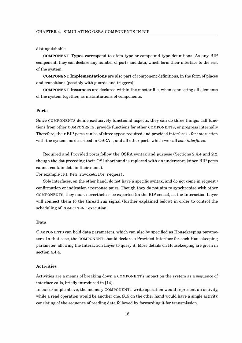
We distinguish three types of activities, depending on the transition patterns they are formed
of:
• Initial Activities, which begin activity chains - those correspond to transitions on a
sequence of one or more pairs of Required Ports. S15’s activity is an example.
• Extending Activities, which extend activity chains - those correspond to transitions on a
pair of Provided Ports with interleaving transitions on pairs of Required Ports. The I2C COM-
19
CHAPTER 4. SIMULATING OSRA COMPONENTS IN BIP
Figure 4.2: A summary of activity types
PONENT implements such an activity, since upon receiving a PI_SimpleI2C_invokeAsk_request
(transition 1), it calls the Execution Layer Device Access service (transitions 2 and 3) before
answering the initial request (transition 4).
• Terminating Activities, which end activity chains - those correspond to transitions on a
pair of Provided Ports without interleaving calls on a pair of Required Ports. The Memory
COMPONENT is an example, since its activities (Read and Write) are made up of Provided
ports and do not trigger other activities.
Figure 4.2 summarises those three patterns.
The only pattern which is not described is one interleaving transitions on pairs of Provided
Ports within a pair of Required Ports. Such a pattern would be useful to COMPONENTS which,
while waiting for an answer on a Required Port, would still make their Provided Ports available
to other COMPONENTS.
20

4.2. COMPONENT LAYER
We do not allow that pattern however, as it makes generating the Interaction Layer more com-
plicated (for reasons discussed in Section 4.3.3), with little benefit; the same behaviour can be
obtained by separating the provided service into another BIP component, and synchronising their
data.
We refer to COMPONENTS which implement initial activities as Initiating COMPONENTS, and
those which implement extending activities as Responding COMPONENTS. Both these types of
COMPONENTS can also implement terminating activities.
Making this distinction is useful when generating the Interaction Layer, as will be discussed
in Section 4.3.3. Indeed, containers ensure deadlock freedom by imposing an order on interactions;
they do so by making use of loop patterns for their transitions. Amongst other things, this ensures
that COMPONENTS do not communicate with the wrong container instance (as will be discussed in
Section 4.3.2, COMPONENTS can be connected to multiple instances of their container). However,
in order to allow extending activities while still ensuring proper coordination, containers must
be less restrictive in their transition patterns; we make up for it by using guards on specific
transitions which act as history variables (discussed in Section 4.3.3), and the knowledge that we
operate under a single-core computational model. That solution however is not compatible with
initial activities, so a container can only support one of both types of COMPONENTS.
Similar issues arise with COMPONENTS leveraging Execution Layer services. In that case however,
history variables are not sufficient. Instead, a way of ensuring that Execution Layer services
reply to the correct container must be implemented. The example described in Chapter 5 does
not have two COMPONENTS which use the same Execution Layer services, which is a sufficient
workaround this issue.
We do not provide a formal proof of the concept of initiating and responding COMPONENTS,
which is beyond the scope of this report.
Contrary to OSRA COMPONENT definitions, which specify only interfaces, BIP component
implementations comprise behaviour, i.e. states and transitions. Hence, the classification made
here relies on BIP concepts and not OSRA specifications.
4.2.2 Additional Constraints when Implementing a COMPONENT
When implementing COMPONENTS, care should be taken with regards to the following:
• It must be possible to classify the COMPONENT as an Initiating or Responding COMPONENT.
So it should not implement both activities which are made of sequences of calls to Required
ports, and activities which make calls to Required ports in between a pair of Provided ports.
• Activities should be identifiable, and should loop between idle states.
21
CHAPTER 4. SIMULATING OSRA COMPONENTS IN BIP
• The final transition of initial activities should be a signal to the Execution Layer that the
activity’s execution is complete. This can be done with the Scheduler_Terminate_indication
primitive, and does not require a response primitive.
• Calls to Execution Layer Services should use the PSEUDO-COMPONENT concept described
in Section (sec:osrael), and be done using regular Required Interface primitives.
• Any internal transition which should only be possible to trigger when the COMPONENT is
executing should be exported, effectively making it a Solo Interface. (See Section 4.3.4.)
• Port types are expected to follow a particular nomenclature, which we describe below.
Nomenclature of Port and Connector Types
A specific nomenclature for port and connector types was chosen, and must be respected for the
Interaction Layer Generation Program to work.
Ports which take no parameter should be of type SyncPort. Ports which do take parameters
should precede the word "Port" with the list of types of their parameters, in order. So a port with
an (int, string, int) signature would have a port type IntStringIntPort.
Regular primitive pairs will have the same signature, so binary connectors will connect ports
of the same type. The Connector’s type will then be "RDV2" followed by the list of upper-case
characters of the first letter for each type in the signature. So two IntStringIntPorts will
be connected by a RDV2ISI connector. Connectors between SyncPorts are simply typed RDV2.
Additionally, some primitive pairs are connected with extra SyncPorts that act as controllers; in
such cases, the connector type is preceded by "ControlledX", if there are X control Ports. Finally,
trigger connections are typed "TriggerN" with N the number of ports connected to the trigger.
These are simplifying restrictions, which can be easily removed by providing appropriate infor-
mation in a separate configuration file.
4.2.3 Properties Definition
Extra properties of the system help specify details such as names of COMPONENT files, Execution
Layer elements to be used, activity chains and more. We discuss the details as to how they should
be declared to the Interaction Layer Generator in Appendix A. The present section lists some of
the important properties which are required.
Components.txt lists all COMPONENT files to be considered by the Interaction Layer Gener-
ation Program, as well as the number of instances of each COMPONENT required.
RespondingAtoms.txt specifies which COMPONENTS are responding atoms.
ActivityChains.txt lists the different activity chains, as a set of intervening COMPONENTS.
ProtectedActivities.txt lists all protected activities.
22

4.3. INTERACTION LAYER
HKParameters.txt declares all parameters which should be included in Housekeeping
reports. They will be used when generating the HkIntermediary component (Section 4.3.7).
4.3 Interaction Layer
Looking back at the list of features mentioned in Section 2.4.2, we describe here the solutions
implemented to answer each of the features. The Interaction Layer hosts three main types of
components to do so :
1. Containers which mediate COMPONENT interfaces, and implement features 1 and 2.
2. Threads which are units of execution.
3. Activators which monitor the frequency of execution, to ensure cyclic, bursty or sporadic
executions of activities.
Threads and activators are combined to implement the computational model.
Additional elements such as locks and housekeeping support can also be present - we discuss
those in sections 4.2.1 and 4.3.7 respectively.
4.3.1 The Computational Model
At the heart of the Interaction Layer’s architecture lies its Computational Model. The OSRA
specification says the following: " The manner in which [the dynamic aspects of the system] are
implemented will depend on the computational model chosen for the system, and the facilities
available from the Execution Platform, which may be implemented with a specific computational
model in mind [10, p. 68-69]."
The model we implemented is inspired by the work described in [14]. We considered a single-
core, multi-thread model. Threads can therefore compete for execution rights, but only one at a
time can be executed. Threads can be assigned priorities, and the Execution Layer is expected to
provide a Scheduler (described in section 4.4.2) to select and signal threads.
Activities run within the context of a thread, and activity calls are exclusively synchronous;
when a new activity is called, it executes on the caller’s thread, while the caller itself waits for
the called activity to complete.
The Execution Layer is also expected to supply Locks for COMPONENTS implementing pro-
tected activities, as well as a mechanism to avoid deadlocks. Those are described in sections 4.3.6
(Locks) and 4.4.3 (Tasking component of the Execution Layer).
23

CHAPTER 4. SIMULATING OSRA COMPONENTS IN BIP
4.3.2 Activity Groups
Activity Groups are a concept which we introduce to handle activity calls within a Thread.
An activity group is a set of COMPONENTS that can be called within the context of the complete
execution of an activity chain. A group is therefore composed of one Initiating COMPONENT - such
as our S15 COMPONENT -, and the set of Responding COMPONENTS involved in the completion of
that activity - Memory by its Read activity, and I2C by its Ask activity.
In our example, we can identify two activity groups:
1. S15, Memory, I2C
2. S13, Memory, I2C
The general architecture of the Interaction Layer uses the notion of activity groups by assign-
ing each of them a thread, an activator, and a matching Container per COMPONENT in the group.
Thread components interact with the Execution Layer’s Scheduler to request and monitor execu-
tion of their group’s activities.
Activator components act as switches on their associated thread, by enabling or disabling execu-
tion. They can be adapted to ensure bursty, sporadic, or cyclic execution patterns.
At the level of the Interaction Layer, activity groups represent individual execution paths
as sequences of COMPONENT interventions. The fact that they are assigned to a single thread
ensures the Computational Model’s requirement that activity calls be executed on the same
thread.
Of course, this implies an overhead on the system size. In the context of a simulation system,
that overhead can however be disregarded. It could be problematic for actual onboard software,
in which case other, more involved approaches can be taken to ensure the same property. This
was not considered useful in the context of this project.
4.3.3 Containers
Containers serve as the interface between COMPONENTS and the rest of the system. Therefore,
copies of a COMPONENT’s Container have to be generated for each Instance of that COMPONENT.
Containers monitor calls from and to their COMPONENT Instance, interact with other containers
to connect required and provided interfaces, and facilitate coordination with the Execution Layer.
Containers are generated based on the parsed interfaces of the Component Layer, and the
non-functional properties specified on the system (Section 4.2.3). Figure 4.3 shows the Container
which was generated for the S15 COMPONENT. We describe each part of it.
24

4.3. INTERACTION LAYER
Figure 4.3: A diagram of the generated Container for the S15 COMPONENT.
Data
All data parameters held by a COMPONENT are copied in its Container. Those copies do not hold
reliable values of the data; they only help pass values through their ports, and are synchronised
when necessary.
Two data parameters are added for protected activity calls: an integer lockStatus and
a string <componentName>_lockID. The former holds the return value of the lock acquisition
request and determines whether or not the lock was obtained; the latter is an immutable value
which is sent to the Execution Layer when requesting a lock as an identification variable.
Containers for Responding COMPONENTS (described in Section 4.2.1) also hold a boolean
expecting_answer. Its use is explained below when discussing Container transitions.
Ports
A container has up to four types of ports:
• Required ports, which are copied from COMPONENTS, and keep the same name and data
parameters (and hence port type). They are connected to their corresponding port in the
COMPONENT.
In Figure 4.3, the pairs of ports numbered (1, 4) and (5, 12) are required ports.
25

CHAPTER 4. SIMULATING OSRA COMPONENTS IN BIP
• Provided ports, which are copied from COMPONENTS, and keep the same name and data
parameters (and hence port type). They are connected to their corresponding port in the
COMPONENT.
In Figure 4.3, the pair of ports numbered (14, 15) is a pair of provided ports.
• Interaction ports, which are generated for each Provided or Required port of the COM-
PONENT. They also work in request/confirmation or indication/response pairs, and are
connected between containers. When a COMPONENT triggers a transition on a Required
port, its Container is notified and will use an Interaction port to notify the appropriate
Container (the one representing the COMPONENT which provides the matching interface).
Thanks to the OSI nomenclature, the appropriate Container can be statically determined
from the Required or Provided primitive itself.
In Figure 4.3, the pairs of ports numbered (2, 3), (8, 9) and (13, 16) are interaction ports.
• Lock ports, which are generated for required ports to protected activities. Those ports are
generated in acquire/release/fail groups, and are used by the container to obtain a lock on
the COMPONENT before using the interaction port to forward the request.
In Figure 4.3, the pairs of ports numbered (6, 7) and (10, 11), as well as the internal
‘internal_fail’ port, are lock ports.
Places
Places of a container are generated based on the type of the ports previously computed for it.
• Required ports pairs : Three places are generated, <activityName>_signal,
<activityName>_fwd and <activityName>_reply.
In Figure 4.3, we have the sets
(read_signal, read_fwd, read_reply) and (ask_signal, ask_fwd, ask_reply).
• Provided ports pairs : If this container belongs to a Responding COMPONENT, two places
are generated, <activityName>_signal and <activityName>_reply. Otherwise, the
<activityName>_fwd place is generated too.
In Figure 4.3, we have the set
(get_s15count_signal, get_s15count_fwd, get_s15count_reply)
since S15 is an initiating COMPONENT.
• Lock ports sets : An additional four places are generated: lock_req, lock_done,
free_req and free_done.
In Figure 4.3, we have the set
(lock_ask_req, lock_ask_done, free_ask_req, free_ask_done).
26
4.3. INTERACTION LAYER
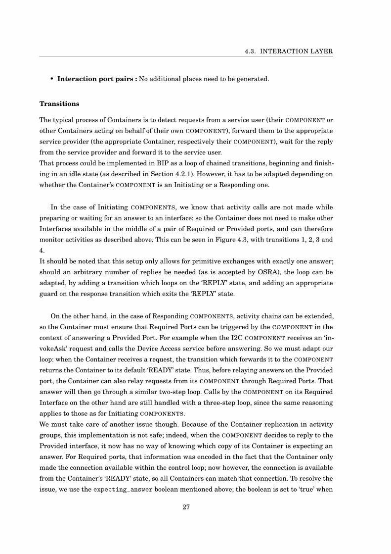
• Interaction port pairs : No additional places need to be generated.
Transitions
The typical process of Containers is to detect requests from a service user (their COMPONENT or
other Containers acting on behalf of their own COMPONENT), forward them to the appropriate
service provider (the appropriate Container, respectively their COMPONENT), wait for the reply
from the service provider and forward it to the service user.
That process could be implemented in BIP as a loop of chained transitions, beginning and finish-
ing in an idle state (as described in Section 4.2.1). However, it has to be adapted depending on
whether the Container’s COMPONENT is an Initiating or a Responding one.
In the case of Initiating COMPONENTS, we know that activity calls are not made while
preparing or waiting for an answer to an interface; so the Container does not need to make other
Interfaces available in the middle of a pair of Required or Provided ports, and can therefore
monitor activities as described above. This can be seen in Figure 4.3, with transitions 1, 2, 3 and
4.
It should be noted that this setup only allows for primitive exchanges with exactly one answer;
should an arbitrary number of replies be needed (as is accepted by OSRA), the loop can be
adapted, by adding a transition which loops on the ‘REPLY’ state, and adding an appropriate
guard on the response transition which exits the ‘REPLY’ state.
On the other hand, in the case of Responding COMPONENTS, activity chains can be extended,
so the Container must ensure that Required Ports can be triggered by the COMPONENT in the
context of answering a Provided Port. For example when the I2C COMPONENT receives an ‘in-
vokeAsk’ request and calls the Device Access service before answering. So we must adapt our
loop: when the Container receives a request, the transition which forwards it to the COMPONENT
returns the Container to its default ‘READY’ state. Thus, before relaying answers on the Provided
port, the Container can also relay requests from its COMPONENT through Required Ports. That
answer will then go through a similar two-step loop. Calls by the COMPONENT on its Required
Interface on the other hand are still handled with a three-step loop, since the same reasoning
applies to those as for Initiating COMPONENTS.
We must take care of another issue though. Because of the Container replication in activity
groups, this implementation is not safe; indeed, when the COMPONENT decides to reply to the
Provided interface, it now has no way of knowing which copy of its Container is expecting an
answer. For Required ports, that information was encoded in the fact that the Container only
made the connection available within the control loop; now however, the connection is available
from the Container’s ‘READY’ state, so all Containers can match that connection. To resolve the
issue, we use the expecting_answer boolean mentioned above; the boolean is set to ‘true’ when
27
CHAPTER 4. SIMULATING OSRA COMPONENTS IN BIP
Figure 4.4: Diagram of the generated Container for the simplified I2C COMPONENT
a request is forwarded to the COMPONENT, and the response transition is guarded with it. That
way, only the Container which received the request will make its transition available.
One should note that this works under the assumption of a single-core model, so only one
activity of a COMPONENT can be executed at a time, and only one Container can enable its
expecting_answer boolean at a time.
Use of the expecting_answer boolean can be seen on Figure 4.4 (where the shorthand ‘exp_ans’
was used for readability).
Dynamic BIP and History Variables
A mechanic similar to the one implemented here with the expecting_answer boolean has been
developed for BIP, under the name Dynamic BIP [6]. The concept is that of history variables;
components use history variables to keep trace of components they have interacted with in the
past, so that they can later rely on that information to make decisions, such as prioritising a
connection with a component with which they had recently interacted.
28
4.3. INTERACTION LAYER
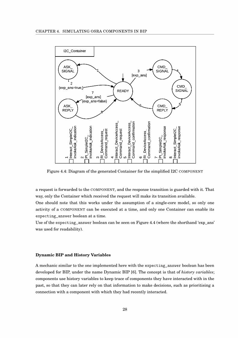
Figure 4.5: Thread component
Figure 4.6: Basic Activa-tor component
Figure 4.7: Lock Compo-nent
4.3.4 Thread
Threads monitor the execution of activities. They can request execution from the Scheduler,
which also has the option of preempting them if another thread of higher priority requests
execution. When a thread is in its ‘EXECUTE’ state (and only then), it provides a ‘run’ port which
is connected to all activity progress - Solo ports which represent COMPONENT progress, as well as
Interact ports which represent activity calls.
Figure 4.5 depicts our implementation of threads; it is based on the design in [14, p. 3], and
modified to suit the Scheduler modifications discussed in Section 4.4.2 - namely the removal of a
queue of threads awaiting execution. Instead, threads who are not granted execution are sent
back to their ‘IDLE’ state through the ‘untrigger’ port, and must request execution again. When
a thread is preempted, it is also sent to the ‘IDLE’ state, and must request execution in the same
way before calling ‘resume’.
This implementation of threads expects activity calls to be synchronous. An implementation
for threads described in [14] handles asynchronous Actactivitiesivities, and requires support for
queuing of activity calls. Since this was not necessary for our case study, we have decided to focus
exclusively on threads with synchronous activity calls.
4.3.5 Activator
Activators act as triggers to the thread they are associated with. Figure 4.6 depicts the most
basic activator: when initialised, it can call the op_start transition, which is connected to the
thread’s trigger port. It can also be stopped at any time.
Three types of activators are specified in [14]:
29
CHAPTER 4. SIMULATING OSRA COMPONENTS IN BIP
• Sporadic Activators have the guarantee that at most one request is released in P units
of time.
• Bursty Activators have the guarantee that a maximum of N request are released in P
units of time.
• Cyclic Activators release one request every P units of time.
4.3.6 Locks
Locks are very straightforward BIP implementations. They provide ‘begin’, ‘locked’ and ‘finish’
ports, and are used by the Tasking service of the Execution Layer (Section 4.4.3).
The Interaction Layer has a lock for each instance of COMPONENTS which provide protected
activities.
4.3.7 HkIntermediary
The HkIntermediary component is only necessary if housekeeping services are required.
OSRA specifies HK support as follows:
"Housekeeping is supported through the reporting interface, as applied to parameters.
The Interaction Layer is expected to map parameters to observable COMPONENT
attributes. [...] It is not possible, using the interface specified here, to control the
content or structure of housekeeping reports. [...]"
The purpose of HkIntermediary is to gather housekeeping reports from the various COMPO-
NENTS (based on the parameters listed in the HkParams.txt file described in Appendix A.3).
When requested by the Reporting service (HkIntermediary_getParameters_indication port), it
will contact all the necessary containers and compose a housekeeping report, which it will then
send back to the Reporting service.
4.4 Execution Layer
4.4.1 LifeCycle
The Lifecycle service described in OSRA provides three functionalities: system initialisation,
system restart, and non-fatal error management.
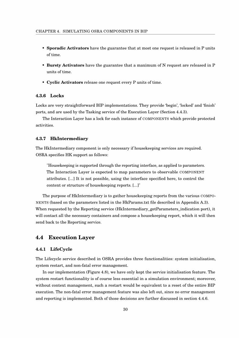
In our implementation (Figure 4.8), we have only kept the service initialisation feature. The
system restart functionality is of course less essential in a simulation environment; moreover,
without context management, such a restart would be equivalent to a reset of the entire BIP
execution. The non-fatal error management feature was also left out, since no error management
and reporting is implemented. Both of those decisions are further discussed in section 4.4.6.
30
4.4. EXECUTION LAYER
Service initialisation was simplified. Whilst OSRA defines initialisation in four steps (Execu-
tion Layer initialisation, Interaction Layer initialisation, Component Layer pre-initialisation,
Component Layer initialisation), the Interaction Layer Generation program will only consider
initialisation of the Interaction Layer; this is done by triggering the ‘init’ port of activators. This
is in particular a simplification to the Interaction Layer Generation, which allowed us to avoid
making the already complicated example described in chapter 5 more complex and hence less
demonstrative of how the framework functions as a whole; nevertheless, it would be straightfor-
ward to extend the script for it to generate the additional connections, along with the necessary
requirements to the design of COMPONENTS.
The LifeCycle service interacts with the Interaction Layer through the activators. Its primi-
tives are connected to the ‘init’ and ‘stop’ ports of the activators.
Figure 4.8: A diagram of the implemented LifeCycle service
4.4.2 Scheduler
OSRA assigns scheduling to the "Tasking And Concurrency" service of the Execution Layer,
which also handles lock allocations. We decided to separate those services for clarity between the
Scheduler and the Tasking components.
The Scheduler supports concurrent execution requests, and determines which thread to
execute based on priority assignments. In our implementation, priorities are handled by the
C code implementation. They could be brought forward into the BIP implementation itself as
discussed below.
Since the system supports both concurrency and locking mechanisms, we need to prevent
deadlocks from occurring. We can do so by implementing an Immediate Ceiling Priority Protocol
[12].
31

CHAPTER 4. SIMULATING OSRA COMPONENTS IN BIP
In ICPP, each lock is assigned the highest priority of all components which may acquire it;
whenever a COMPONENT does acquire the lock, its priority is immediately changed to that ceiling
priority. When the COMPONENT releases the lock, it returns to its original priority.
A formal application of ICPP requires support for dynamic priorities. This is not the case of our
implementation; thus as a workaround, we assign an absolute ceiling priority to any COMPONENT
which acquires a lock, effectively making it impossible to preempt it until it has released all the
locks it acquired. This is sufficient to ensure the safety property of ICPP (i.e. no deadlocks can
occur); however, it prevents processes with a priority higher than an active ceiling priority from
executing.
A Note on Support for Dynamic PrioritiesFor the system to support dynamic thread priorities, it would need a way to propagate
information on process priorities throughout the system. One way of doing so would
be to have a component which holds a table keeping track of the priorities of all the
threads. The Tasking service could then inform it of threads obtaining or releasing
locks, and the Scheduler service could query it for information on processes requesting
execution.
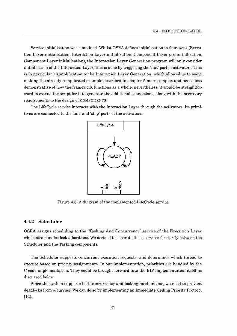
When a thread wants to run (‘trigger’ port), it will synchronise on the ‘request’ port of the
Scheduler (number 1 in Figure 4.9), passing along its ID. If no thread is currently executing, that
thread will be scheduled, and called. If another thread is executing, the Scheduler will compare
thread priorities using the ‘next()’ method in the ‘get_priorities’ transition (number 3); if the new
thread has a higher priority, the current thread is preempted (port number 4) and the new one
scheduled and called; otherwise, the new thread’s request is cancelled (port number 6), which
will send it back to its ‘IDLE’ state (connected to the Thread’s ‘untrigger’ port).
The ‘call_X’ port (number 5) is replicated for each thread in the system, and connected to a
single thread’s ‘exec’ port.
The ‘finish’ port (number 7) is connected to the threads’ ‘finish’ ports, and allows them to
notify the Scheduler when execution is completed.
The ‘icpp_start’ and ‘icpp_end’ ports are used to simulate the adapted ICPP as described
above. They act as a switch on the Scheduler, preventing it from detecting execution and requests,
and therefore from preempting a thread which acquired a lock. The Tasking service synchronises
lock acquisitions and releases with those ports; this is discussed in Section 4.4.3.
4.4.3 Tasking
The Execution Layer’s Tasking service is in charge of Lock assignment and release. The OSRA
definition also puts it in charge of scheduling threads, though we chose to break the two aspects
apart for clarity.
32
4.4. EXECUTION LAYER
Figure 4.9: Diagram of the Execution Layer’s Scheduler service
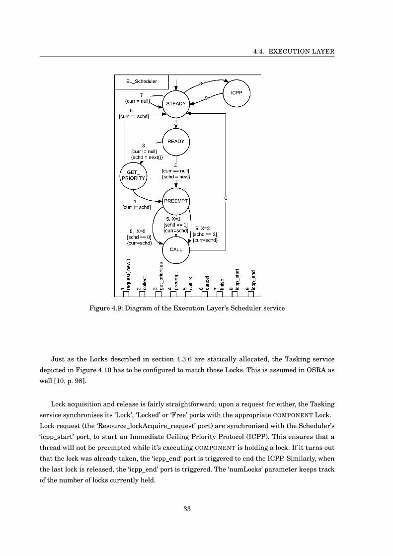
Just as the Locks described in section 4.3.6 are statically allocated, the Tasking service
depicted in Figure 4.10 has to be configured to match those Locks. This is assumed in OSRA as
well [10, p. 98].
Lock acquisition and release is fairly straightforward; upon a request for either, the Tasking
service synchronises its ‘Lock’, ‘Locked’ or ‘Free’ ports with the appropriate COMPONENT Lock.
Lock request (the ‘Resource_lockAcquire_request’ port) are synchronised with the Scheduler’s
‘icpp_start’ port, to start an Immediate Ceiling Priority Protocol (ICPP). This ensures that a
thread will not be preempted while it’s executing COMPONENT is holding a lock. If it turns out
that the lock was already taken, the ‘icpp_end’ port is triggered to end the ICPP. Similarly, when
the last lock is released, the ‘icpp_end’ port is triggered. The ‘numLocks’ parameter keeps track
of the number of locks currently held.
33
CHAPTER 4. SIMULATING OSRA COMPONENTS IN BIP
Figure 4.10: Diagram of the Execution Layer’s Tasking service
4.4.4 Reporting
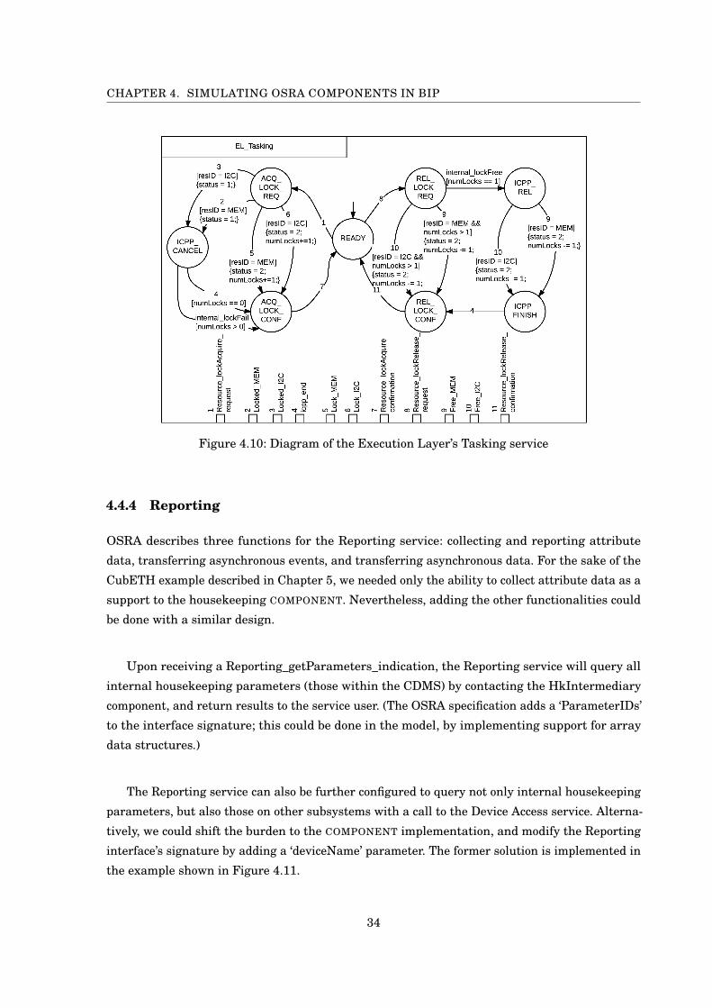
OSRA describes three functions for the Reporting service: collecting and reporting attribute
data, transferring asynchronous events, and transferring asynchronous data. For the sake of the
CubETH example described in Chapter 5, we needed only the ability to collect attribute data as a
support to the housekeeping COMPONENT. Nevertheless, adding the other functionalities could
be done with a similar design.
Upon receiving a Reporting_getParameters_indication, the Reporting service will query all
internal housekeeping parameters (those within the CDMS) by contacting the HkIntermediary
component, and return results to the service user. (The OSRA specification adds a ‘ParameterIDs’
to the interface signature; this could be done in the model, by implementing support for array
data structures.)
The Reporting service can also be further configured to query not only internal housekeeping
parameters, but also those on other subsystems with a call to the Device Access service. Alterna-
tively, we could shift the burden to the COMPONENT implementation, and modify the Reporting
interface’s signature by adding a ‘deviceName’ parameter. The former solution is implemented in
the example shown in Figure 4.11.
34
4.4. EXECUTION LAYER
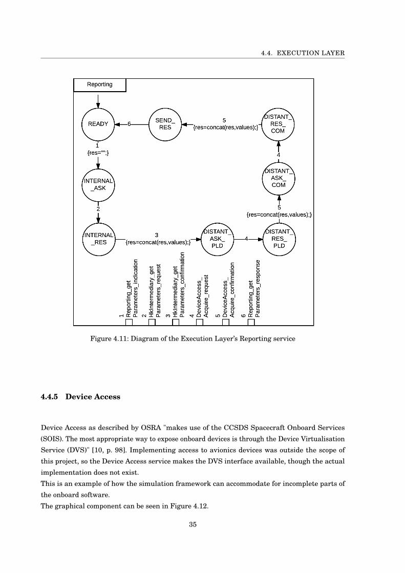
Figure 4.11: Diagram of the Execution Layer’s Reporting service
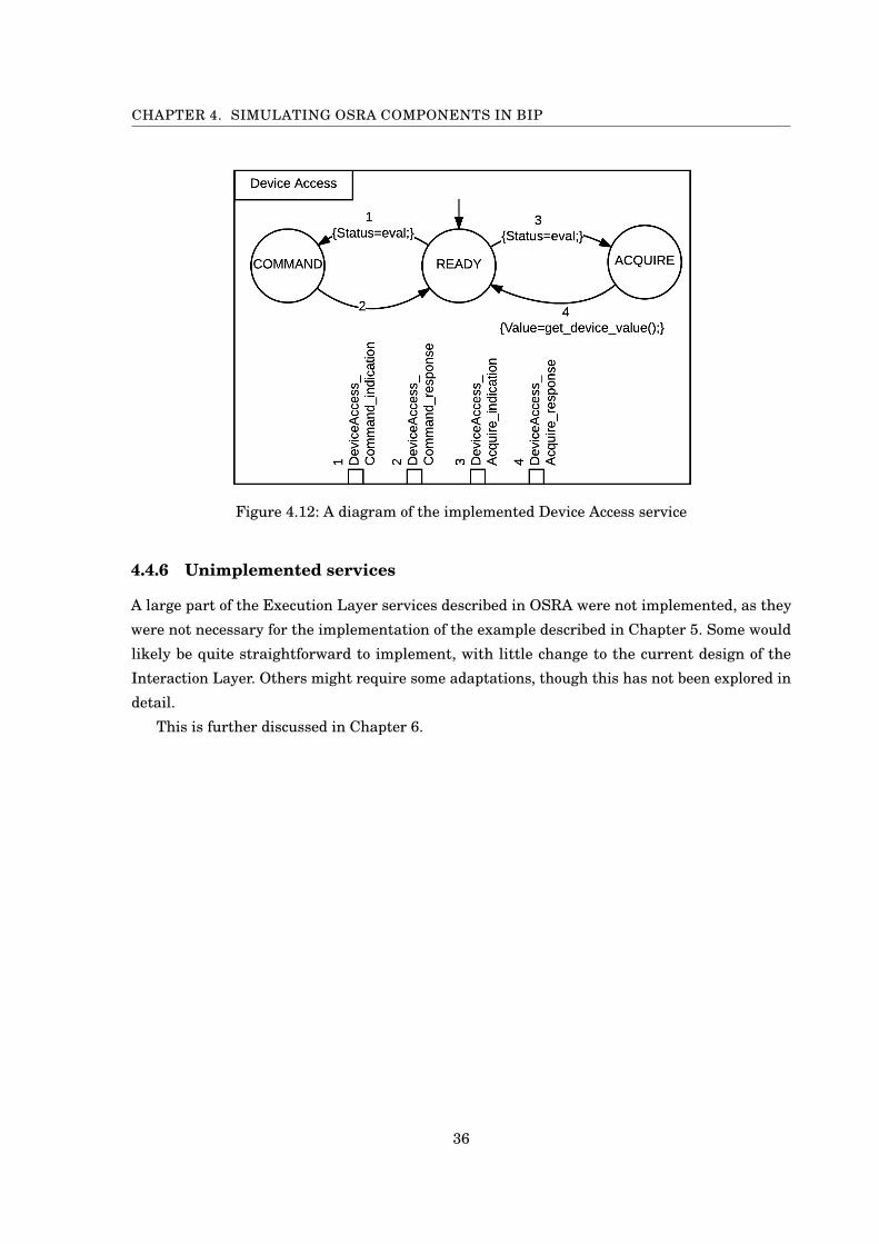
4.4.5 Device Access
Device Access as described by OSRA "makes use of the CCSDS Spacecraft Onboard Services
(SOIS). The most appropriate way to expose onboard devices is through the Device Virtualisation
Service (DVS)" [10, p. 98]. Implementing access to avionics devices was outside the scope of
this project, so the Device Access service makes the DVS interface available, though the actual
implementation does not exist.
This is an example of how the simulation framework can accommodate for incomplete parts of
the onboard software.
The graphical component can be seen in Figure 4.12.
35
CHAPTER 4. SIMULATING OSRA COMPONENTS IN BIP
Figure 4.12: A diagram of the implemented Device Access service
4.4.6 Unimplemented services
A large part of the Execution Layer services described in OSRA were not implemented, as they
were not necessary for the implementation of the example described in Chapter 5. Some would
likely be quite straightforward to implement, with little change to the current design of the
Interaction Layer. Others might require some adaptations, though this has not been explored in
detail.
This is further discussed in Chapter 6.
36

CH
AP
TE
R
5CUBETH CASE STUDY
This chapter describes implementing some of the functionality of the CubETH, using the
BIP simulation platform described in Chapter 4.
5.1 CubETH
CubETH is a nanosatellite of the cubesat family, developed in Switzerland. It is an iteration on
the Swisscube satellite, which has been in orbit for the past seven years, successfully monitoring
a set of parameters observable in a live feed. [3].
In the context of a project accomplished at EPFL’s Space Engineering Lab (eSpace), a BIP
model of the satellite’s Command and Data Management System (CDMS) was developed [11].
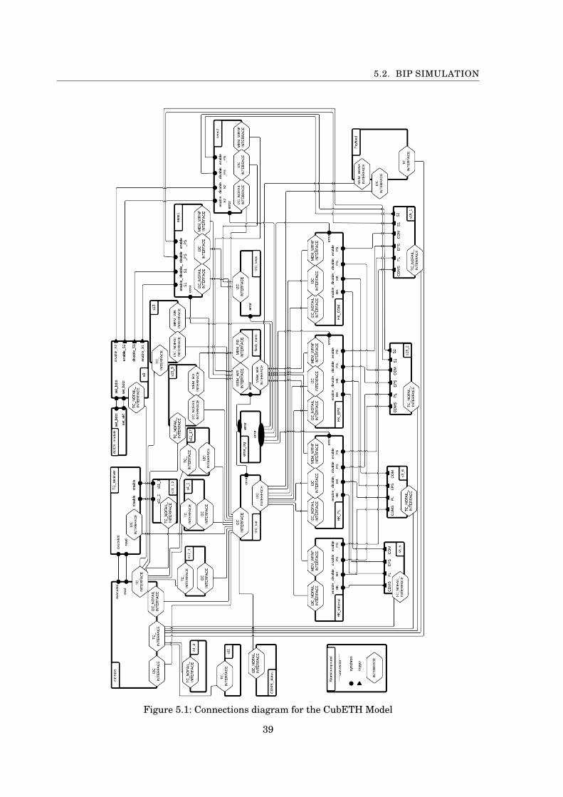
Within it, control of the different subsystems (Payload, Energy, ...) and overall management of the
satellite was clearly broken down into different components. Figure 5.1 (from [11, p. 34]) shows
the complete model’s connections. We refer to it as the CubETH Model.
The advantage stemming from the design of such a system in BIP was to simplify its vali-
dation: components can be proved correct by construction, isolating the verification efforts to
the interactions between them. Indeed, the complete system is a complex web of collaborating
services, one which is difficult to analyse, verify, and modify. A previous project explored feasible
ways of validating the design [13].
By using the platform developed in the present project, we were able to reuse a subset of the
components defined in the cubETH model, and to generate their interactions as an Interaction
Layer.
In this chapter, we describe the components that were reused, how they were adapted, and
37

CHAPTER 5. CUBETH CASE STUDY
how they could be connected as a single system by the Interaction Layer generation program.
5.2 BIP Simulation
In order to demonstrate some essential functionalities of the system implemented in the CubETH
Model, while also keeping the system simple enough for the purpose of this report, we selected
five components to reuse from the original model: Flash_Memory, I2C_Sat, Services 13 and 15,
and the global HK system. Those were then adapted to fit the design constraints explained
in Chapter 4, and their implementation was simplified when possible without fundamentally
altering the Component’s behaviour.
Simplified versions of some components were already introduced in Chapter 4.
We now go over each Component in detail, providing a diagram of each, and discussing the
Execution Layer functionalities which they leverage. In order to keep diagrams legible, port
signatures are provided separately, as they are important to understand the assigning of data
values throughout the system.
Finally, we give a complete diagram of the connected system, and an example of its output.
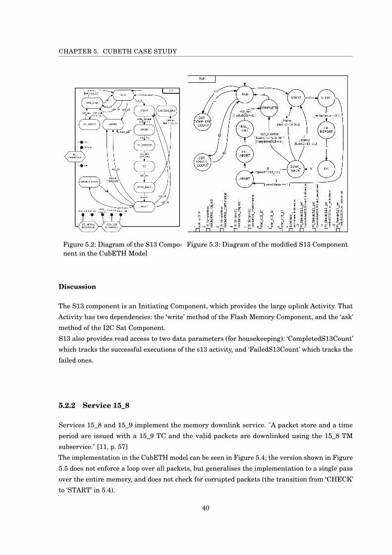
5.2.1 Service 13
Service 13 implements the large uplink service. "A large uplink is initiated by a 13_9 TC,
progressed by a 13_10 TC and terminated with a 13_11 TC. A 13_12 TC can be issued anytime to
abort the uplink." [11, p. 56]
The implementation in the CubETH model can be seen in Figure 5.2; the version implemented in
Figure 5.3 is very similar, losing only the tolerance to wrong starts for clarity purposes.
Ports
- SyncPort RI_SimpleMem_invokeWrite_request()
IntPort RI_SimpleMem_invokeWrite_confirmation(writeStatus)
- SyncPort RI_SimpleI2C_invokeAsk_request()
IntPort RI_SimpleI2C_invokeAsk_confirmation(I2CStatus)
- SyncPort Scheduler_terminate_indication()
- SyncPort PI_SimpleS13_getCompletedS13Count_indication()
IntPort PI_SimpleS13_getCompletedS13Count_response(CompletedS13Count)
- SyncPort PI_SimpleS13_getFailedS13Count_indication()
IntPort PI_SimpleS13_getFailedS13Count_response(FailedS13Count)
38
5.2. BIP SIMULATION
Figure 5.1: Connections diagram for the CubETH Model
39
CHAPTER 5. CUBETH CASE STUDY
Figure 5.2: Diagram of the S13 Compo-nent in the CubETH Model
Figure 5.3: Diagram of the modified S13 Component
Discussion
The S13 component is an Initiating Component, which provides the large uplink Activity. That
Activity has two dependencies: the ‘write’ method of the Flash Memory Component, and the ‘ask’
method of the I2C Sat Component.
S13 also provides read access to two data parameters (for housekeeping): ‘CompletedS13Count’
which tracks the successful executions of the s13 activity, and ‘FailedS13Count’ which tracks the
failed ones.
5.2.2 Service 15_8
Services 15_8 and 15_9 implement the memory downlink service. "A packet store and a time
period are issued with a 15_9 TC and the valid packets are downlinked using the 15_8 TM
subservice." [11, p. 57]
The implementation in the CubETH model can be seen in Figure 5.4; the version shown in Figure
5.5 does not enforce a loop over all packets, but generalises the implementation to a single pass
over the entire memory, and does not check for corrupted packets (the transition from ‘CHECK’
to ‘START’ in 5.4).
40

5.2. BIP SIMULATION
Figure 5.4: Diagram of the S15 Compo-nent in the CubETH Model
Figure 5.5: Diagram of the modified S15 Component
Ports
- SyncPort RI_SimpleMem_invokeRead_request()
IntPort RI_SimpleMem_invokeRead_confirmation(readStatus)
- SyncPort RI_SimpleI2C_invokeAsk_request()
IntPort RI_SimpleI2C_invokeAsk_confirmation(I2CStatus)
- SyncPort Scheduler_terminate_indication()
- SyncPort PI_SimpleS15_getCompletedS15Count_indication()
IntPort PI_SimpleS15_getCompletedS15Count_response(CompletedS15Count)
Discussion
The S15 component is an Initiating Component, which provides the memory downlink Activity.
That Activity has two dependencies: the ‘read’ method of the Flash Memory Component, and the
‘ask’ method of the I2C Sat Component.
41
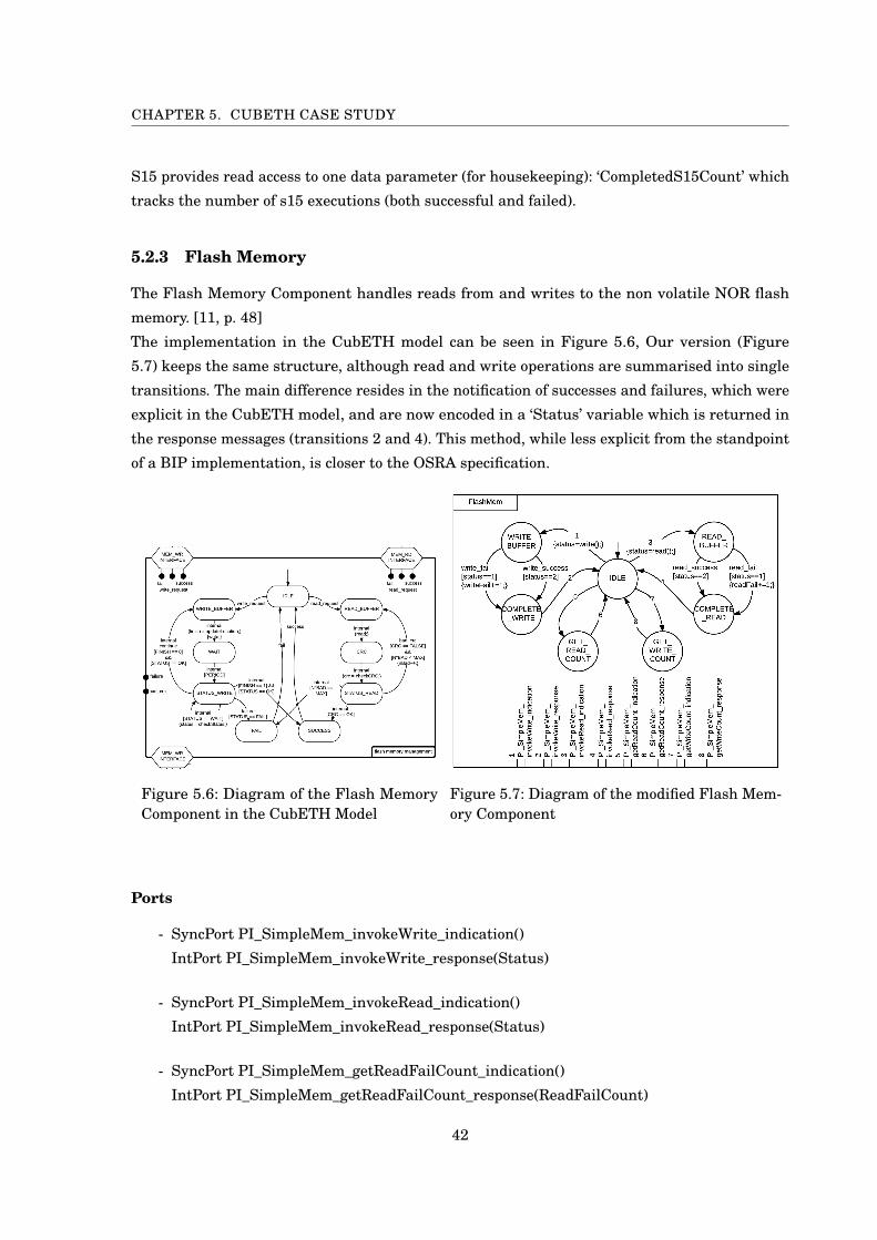
CHAPTER 5. CUBETH CASE STUDY
S15 provides read access to one data parameter (for housekeeping): ‘CompletedS15Count’ which
tracks the number of s15 executions (both successful and failed).
5.2.3 Flash Memory
The Flash Memory Component handles reads from and writes to the non volatile NOR flash
memory. [11, p. 48]
The implementation in the CubETH model can be seen in Figure 5.6, Our version (Figure
5.7) keeps the same structure, although read and write operations are summarised into single
transitions. The main difference resides in the notification of successes and failures, which were
explicit in the CubETH model, and are now encoded in a ‘Status’ variable which is returned in
the response messages (transitions 2 and 4). This method, while less explicit from the standpoint
of a BIP implementation, is closer to the OSRA specification.
Figure 5.6: Diagram of the Flash MemoryComponent in the CubETH Model
Figure 5.7: Diagram of the modified Flash Mem-ory Component
Ports
- SyncPort PI_SimpleMem_invokeWrite_indication()
IntPort PI_SimpleMem_invokeWrite_response(Status)
- SyncPort PI_SimpleMem_invokeRead_indication()
IntPort PI_SimpleMem_invokeRead_response(Status)
- SyncPort PI_SimpleMem_getReadFailCount_indication()
IntPort PI_SimpleMem_getReadFailCount_response(ReadFailCount)
42
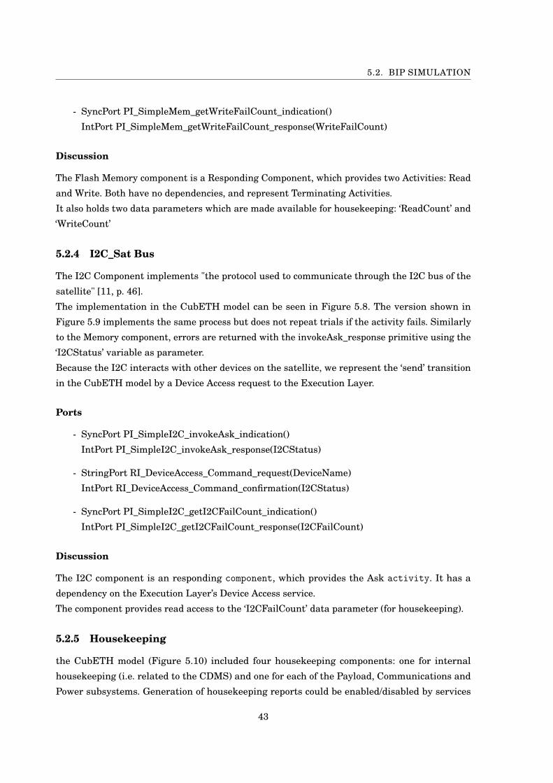
5.2. BIP SIMULATION
- SyncPort PI_SimpleMem_getWriteFailCount_indication()
IntPort PI_SimpleMem_getWriteFailCount_response(WriteFailCount)
Discussion
The Flash Memory component is a Responding Component, which provides two Activities: Read
and Write. Both have no dependencies, and represent Terminating Activities.
It also holds two data parameters which are made available for housekeeping: ‘ReadCount’ and
‘WriteCount’
5.2.4 I2C_Sat Bus
The I2C Component implements "the protocol used to communicate through the I2C bus of the
satellite" [11, p. 46].
The implementation in the CubETH model can be seen in Figure 5.8. The version shown in
Figure 5.9 implements the same process but does not repeat trials if the activity fails. Similarly
to the Memory component, errors are returned with the invokeAsk_response primitive using the
‘I2CStatus’ variable as parameter.
Because the I2C interacts with other devices on the satellite, we represent the ‘send’ transition
in the CubETH model by a Device Access request to the Execution Layer.
Ports
- SyncPort PI_SimpleI2C_invokeAsk_indication()
IntPort PI_SimpleI2C_invokeAsk_response(I2CStatus)
- StringPort RI_DeviceAccess_Command_request(DeviceName)
IntPort RI_DeviceAccess_Command_confirmation(I2CStatus)
- SyncPort PI_SimpleI2C_getI2CFailCount_indication()
IntPort PI_SimpleI2C_getI2CFailCount_response(I2CFailCount)
Discussion
The I2C component is an responding component, which provides the Ask activity. It has a
dependency on the Execution Layer’s Device Access service.
The component provides read access to the ‘I2CFailCount’ data parameter (for housekeeping).
5.2.5 Housekeeping
the CubETH model (Figure 5.10) included four housekeeping components: one for internal
housekeeping (i.e. related to the CDMS) and one for each of the Payload, Communications and
Power subsystems. Generation of housekeeping reports could be enabled/disabled by services
43
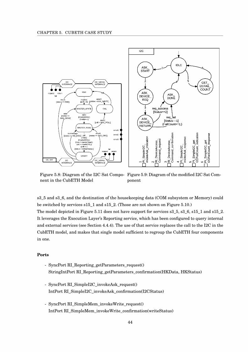
CHAPTER 5. CUBETH CASE STUDY
Figure 5.8: Diagram of the I2C Sat Compo-nent in the CubETH Model
Figure 5.9: Diagram of the modified I2C Sat Com-ponent
s3_5 and s3_6, and the destination of the housekeeping data (COM subsystem or Memory) could
be switched by services s15_1 and s15_2. (Those are not shown on Figure 5.10.)
The model depicted in Figure 5.11 does not have support for services s3_5, s3_6, s15_1 and s15_2.
It leverages the Execution Layer’s Reporting service, which has been configured to query internal
and external services (see Section 4.4.4). The use of that service replaces the call to the I2C in the
CubETH model, and makes that single model sufficient to regroup the CubETH four components
in one.
Ports
- SyncPort RI_Reporting_getParameters_request()
StringIntPort RI_Reporting_getParameters_confirmation(HKData, HKStatus)
- SyncPort RI_SimpleI2C_invokeAsk_request()
IntPort RI_SimpleI2C_invokeAsk_confirmation(I2CStatus)
- SyncPort RI_SimpleMem_invokeWrite_request()
IntPort RI_SimpleMem_invokeWrite_confirmation(writeStatus)
44
5.2. BIP SIMULATION
Figure 5.10: Diagram of the InternalHousekeeping Component in the Cu-bETH Model
Figure 5.11: Diagram of the modified HousekeepingComponent
- SyncPort Scheduler_terminate_indication()
Discussion
The Housekeeping component is an Initiating Component, which provides the housekeeping Ac-
tivity. It has three dependencies: the ‘getParameters’ method of the Execution Layer’s Reporting
service, the ‘write’ method of the Flash Memory Component, and the ‘ask’ method of the I2C Sat
Component.
5.2.6 Non-functional Properties
The following non-functional properties were declared for the system.
Housekeeping Parameters:
45
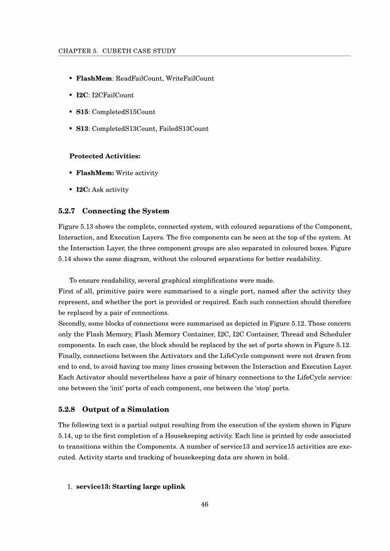
CHAPTER 5. CUBETH CASE STUDY
• FlashMem: ReadFailCount, WriteFailCount
• I2C: I2CFailCount
• S15: CompletedS15Count
• S13: CompletedS13Count, FailedS13Count
Protected Activities:
• FlashMem: Write activity
• I2C: Ask activity
5.2.7 Connecting the System
Figure 5.13 shows the complete, connected system, with coloured separations of the Component,
Interaction, and Execution Layers. The five components can be seen at the top of the system. At
the Interaction Layer, the three component groups are also separated in coloured boxes. Figure
5.14 shows the same diagram, without the coloured separations for better readability.
To ensure readability, several graphical simplifications were made.
First of all, primitive pairs were summarised to a single port, named after the activity they
represent, and whether the port is provided or required. Each such connection should therefore
be replaced by a pair of connections.
Secondly, some blocks of connections were summarised as depicted in Figure 5.12. Those concern
only the Flash Memory, Flash Memory Container, I2C, I2C Container, Thread and Scheduler
components. In each case, the block should be replaced by the set of ports shown in Figure 5.12.
Finally, connections between the Activators and the LifeCycle component were not drawn from
end to end, to avoid having too many lines crossing between the Interaction and Execution Layer.
Each Activator should nevertheless have a pair of binary connections to the LifeCycle service:
one between the ‘init’ ports of each component, one between the ‘stop’ ports.
5.2.8 Output of a Simulation
The following text is a partial output resulting from the execution of the system shown in Figure
5.14, up to the first completion of a Housekeeping activity. Each line is printed by code associated
to transitions within the Components. A number of service13 and service15 activities are exe-
cuted. Activity starts and tracking of housekeeping data are shown in bold.
1. service13: Starting large uplink
46
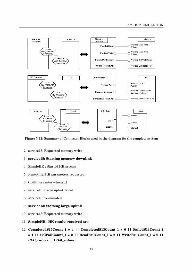
5.2. BIP SIMULATION
Figure 5.12: Summary of Connector Blocks used in the diagram for the complete system
2. service13: Requested memory write
3. service15: Starting memory downlink
4. SimpleHK : Started HK process
5. Reporting: HK parameters requested
6. (...40 more interactions...)
7. service13: Large uplink failed
8. service13: Terminated
9. service13: Starting large uplink
10. service13: Requested memory write
11. SimpleHK : HK results received are:
12. CompletedS15Count_1 = 4 || CompletedS13Count_1 = 0 || FailedS13Count_1= 1 || I2CFailCount_1 = 2 || ReadFailCount_1 = 2 || WriteFailCount_1 = 0 ||PLD_values || COM_values
47
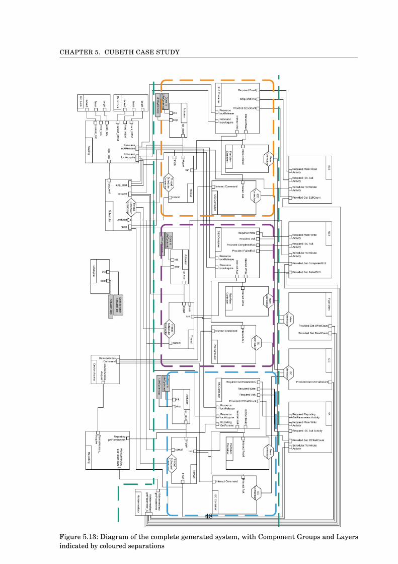
CHAPTER 5. CUBETH CASE STUDY
Figure 5.13: Diagram of the complete generated system, with Component Groups and Layersindicated by coloured separations
48
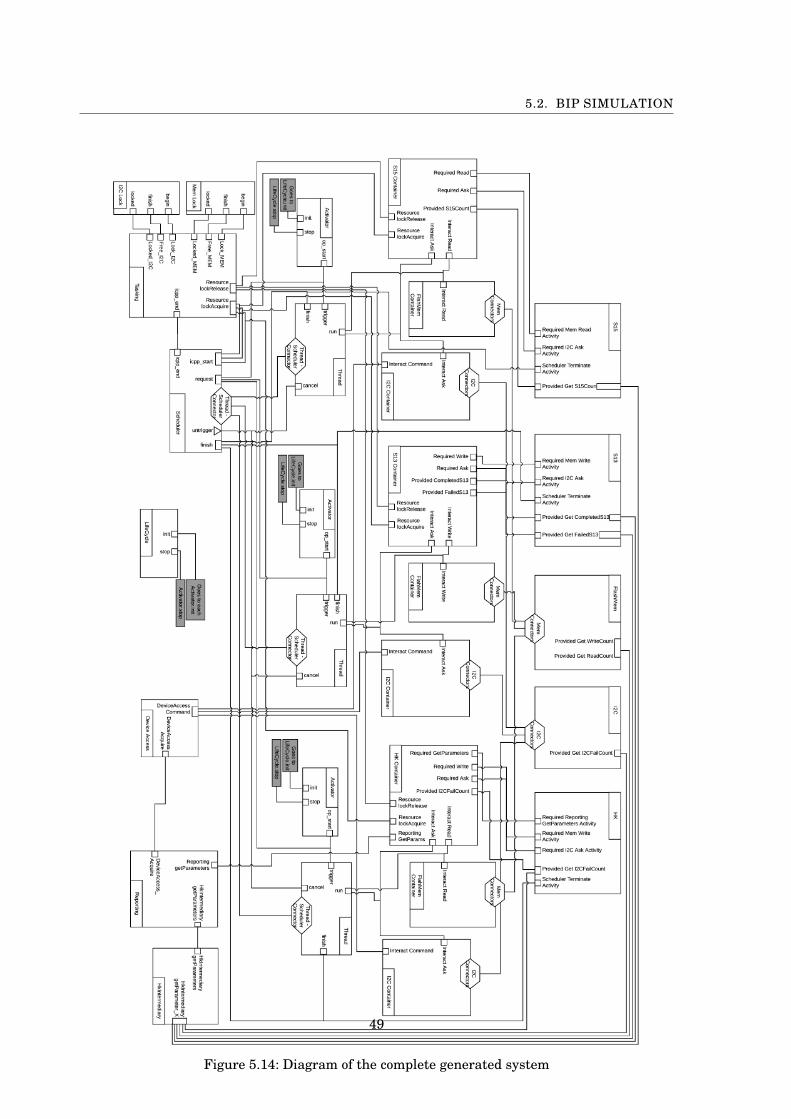
5.2. BIP SIMULATION
Figure 5.14: Diagram of the complete generated system
49

CHAPTER 5. CUBETH CASE STUDY
13. Flash_Mem: Write was successful.
14. service13: Memory write succeeded
15. SimpleHK : Completed successfully
50
CH
AP
TE
R
6FUTURE WORK
In order to bring the framework described in this report to a higher level of maturity, the next
steps to perform can go in two directions: either extending the framework’s functionality,
or further validating its design and evaluating its performance.
Extending the framework’s functionality would involve implementing more of the OSRA elements.
In particular, Execution Layer services that were left out or only partially implemented. In turn,
this would allow to support more of the services used by the CubETH Model. Indeed, the
Reporting services would have to be extended for components s3 and s4, Commanding services
would be required for s8, and Automation services for s11 [10, p. 99]. Components S13, s15 and
s17 "are expected to be entirely internal to the Execution Platform" [10, p. 100], and should be
implemented along those lines.
The performance of the generated code should be evaluated, in order to determine the impact
of some of the design decisions (activity groups in particular) that were made. That would
help determine modifications which are necessary should we want to use the framework in a
different context (validation, deployment etc.). Depending on the performance results observed,
the Interaction Layer generation should be optimised. It would then be interesting to explore
possible synergies with Architecture Based Design principles [5] [9], which could help with
validation efforts of the design.
51


CH
AP
TE
R
7CONCLUSION
We designed and implemented a framework facilitating the design of OSRA-compliant
BIP systems. Given a set of application components developed in BIP, the framework
provides a parametrised implementation of the Execution Layer, and automates the
generation of the Interaction Layer. It relies on a single-core, multi-threaded computational
model.
The primary use for such a system is simulation, verification and testing, although the automatic
generation of C++ code provided by the BIP framework makes deployment on target platforms
possible.
To the best of our knowledge, this is the first published implementation of a framework leveraging
the OSRA’s reference architecture to automate the generation of an Interaction Layer. It removes
the burden of considering concurrency issues from the software engineer, and can considerably
improve the development speed of systems, since the Interaction Layer does not need to be
adapted "by hand" upon each iteration.
We were able to successfully use the framework in order to implement a subset of the functionali-
ties implemented in a previously designed model for the CubETH. Based on an adapted set of
components and an implementation of the Execution Layer, the Interaction Layer generation
program was able to build a complete executable BIP system.
53


CH
AP
TE
R
8ACKNOWLEDGEMENTS
Special thanks to Jean-Yves Le Boudec, for agreeing to supervise this project. To Anton Ivanov
for his invaluable help providing information in the field of space engineering.
Very special thanks to Simon Bliudze for offering advice on the report, and for keeping his door
open at all times.
55

AP
PE
ND
IX
AINTERACTION LAYER GENERATION
We describe in this chapter the process of generating the Interaction Layer. This is
done using a program written in Scala, which takes as input the set of Components
from the Component Layer, as well as all extra non-functional properties required. We
first provide a short description of the Scala programming language and the ParserCombinator
Library. We then describe how the program works.
A.1 Scala
Scala is an acronym for "Scalable Language". It is a programming language which compiles
to java bytecode, allowing it to run on the Java Virtual Machine (JVM) and providing it with
a strong interoperability with Java. Most importantly, it is a hybrid programming language,
providing both object-oriented and functional programming paradigms. This versatility makes it
both a strong scripting language - for quick writing of short, efficient bits of code -, as well as one
that provides a rigorous structure to code and a strong typing system.
Scala’s scalability property motivated its choice for the development of the Interaction Layer
Generator; for the sake of this project, the generator was not expected to be vastly detailed, and
the functional programming capabilities of Scala made it possible to develop it quickly, while also
preparing for future developments thanks to the language’s ability to cleanly expand on an initial
iteration of the program.
A.1.1 The ParserCombinator Library
Scala provides a ParserCombinator library - a set of tools that helps with parsing code and
generating tokens. This library was instrumental in this project, as the Interaction Layer can be
57

APPENDIX A. INTERACTION LAYER GENERATION
entirely inferred through parsing interfaces and data of the Component Layer, as discussed in
Chapter 4.
The library offers two main concepts: Parsers, which are methods that can be configured
to recognise certain parts of a text they are applied to (regular expressions for example); and
Combinators, which combine several Parsers into a new one. A detailed tutorial can be found at
[8], amongst many others online.
A.2 Interaction Layer Generation
The code which generates the Interaction Layer expects the following input:
- A valid BIP implementation of the component layer, into different bip files. Each component
is expected to be a single atom or compound.
- A complete list of resource files, as specified in Section A.3.
The generation itself is then done in five steps:
1. Parse all components and provided resources
2. Build the Interaction Layer components using the results of parsing
3. Build the system by connecting all the layers.
4. Generate the appropriate files from all the computed data
We give a brief description of each step in turn. Detailed comments are attached to the
program’s code.
A.2.1 Parsing
The parsing step consists of two parts: building the parser, and applying it to our files.
A.2.1.1 Building the Parser
Building the parser begins with defining tokens for the different types of constructs we need to
recognise. Those tokens are simple Scala case classes which we later use to determine the type of
token we are dealing with. Each token type is associated with a Parser method, as described in
section A.1.1. Those methods are then used by the parser to generate a list of tokens out of the
entire code.
We only need to parse the data and ports of the BIP components, though we have to distinguish
three different types of ports.
We therefore define parsers for four token types: data parameters, required interfaces, provided
interfaces, and solo interfaces, and combine them into a global parser, that returns a list of all
the recognised tokens.
58

A.2. INTERACTION LAYER GENERATION
A.2.1.2 Applying the Parser
The code that calls the parser applies it to all of the components declared in the ‘Components.txt’
file. Each list of Tokens obtained is attached to the instance name of the component it matches (or
the several instances if such is the case), and the pairs are then added to a Map, from instance
name to tokens. That Map is then passed to the refining step.
A.2.2 Building Components
With the list of Tokens generated by the parsing step, we now want to create the interaction layer
containers for the components.
The code contains a class representing BIP Atoms, which is used to store all the Atom’s
information before printing it to file in the later stages of the code generation:
1 case class AtomDecomp(2 componentName: String, // E.g. SimpleMem_Container3 atomName: String, // E.g. SimpleMem4 data: List[DataTokens],5 ports: List[PortToken],6 places: List[PlaceToken],7 transitions: List[TransitionToken],8 isProtected: Boolean, // Whether this component hold a protected activity9 additionalPorts: List[PortToken], // Holds all solo ports
10 initialPlace: String, // Place to which the atom initialises11 initialDataSetup: List[String] // Allows to provide code that will initialise data parameters12 )
We then sort all the tokens into separate lists, and infer the missing pieces to generate
AtomDecomps for our containers, as described in Section 4.3.3
A.2.3 Building the System Compound
The system compound, where all the components are connected, is generated last.
It starts by determining component groups, and adding threads, activators and locks as necessary.
The implementations for those are specified in another scala file: ComponentTemplates.scala.
That file also specifies the BIP implementation of the HkIntermediary component. It can be
extended to support other types of constructs as well.
Finally, the connections are created, as instances of a Connector class.
A.2.4 Writing to File
Each class used throughout the program has a ‘prettyprint’ method defined. Using those, it is
straightforward to generate the appropriate BIP implementations as individual files.
59
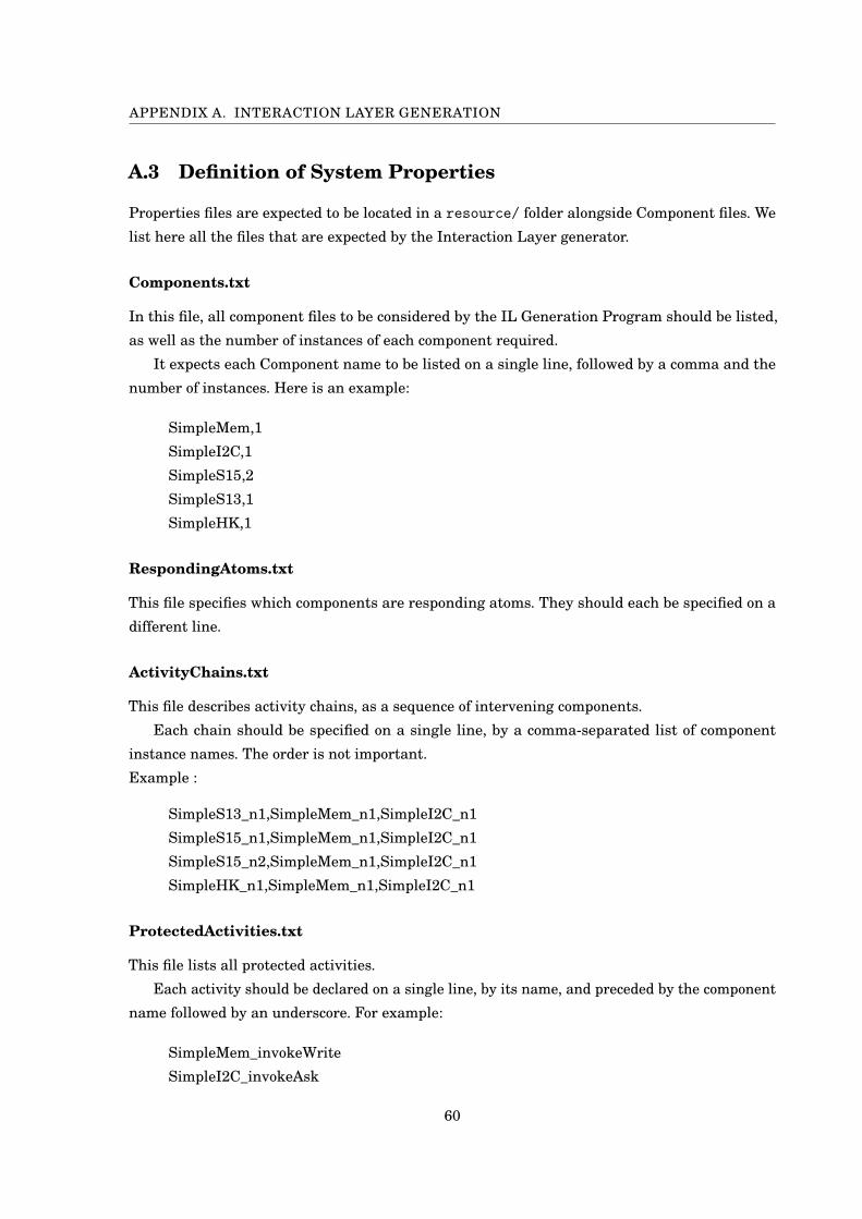
APPENDIX A. INTERACTION LAYER GENERATION
A.3 Definition of System Properties
Properties files are expected to be located in a resource/ folder alongside Component files. We
list here all the files that are expected by the Interaction Layer generator.
Components.txt
In this file, all component files to be considered by the IL Generation Program should be listed,
as well as the number of instances of each component required.
It expects each Component name to be listed on a single line, followed by a comma and the
number of instances. Here is an example:
SimpleMem,1
SimpleI2C,1
SimpleS15,2
SimpleS13,1
SimpleHK,1
RespondingAtoms.txt
This file specifies which components are responding atoms. They should each be specified on a
different line.
ActivityChains.txt
This file describes activity chains, as a sequence of intervening components.
Each chain should be specified on a single line, by a comma-separated list of component
instance names. The order is not important.
Example :
SimpleS13_n1,SimpleMem_n1,SimpleI2C_n1
SimpleS15_n1,SimpleMem_n1,SimpleI2C_n1
SimpleS15_n2,SimpleMem_n1,SimpleI2C_n1
SimpleHK_n1,SimpleMem_n1,SimpleI2C_n1
ProtectedActivities.txt
This file lists all protected activities.
Each activity should be declared on a single line, by its name, and preceded by the component
name followed by an underscore. For example:
SimpleMem_invokeWrite
SimpleI2C_invokeAsk
60
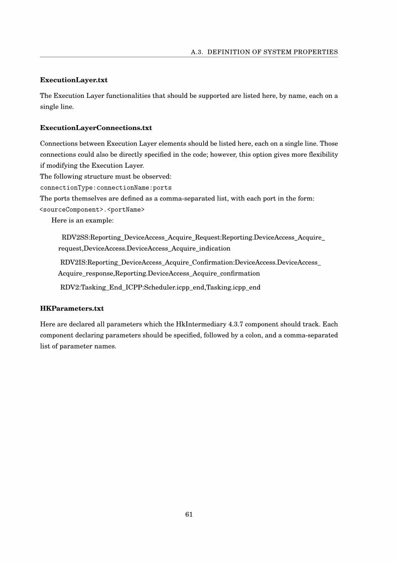
A.3. DEFINITION OF SYSTEM PROPERTIES
ExecutionLayer.txt
The Execution Layer functionalities that should be supported are listed here, by name, each on a
single line.
ExecutionLayerConnections.txt
Connections between Execution Layer elements should be listed here, each on a single line. Those
connections could also be directly specified in the code; however, this option gives more flexibility
if modifying the Execution Layer.
The following structure must be observed:
connectionType:connectionName:ports
The ports themselves are defined as a comma-separated list, with each port in the form:
<sourceComponent>.<portName>
Here is an example:
RDV2SS:Reporting_DeviceAccess_Acquire_Request:Reporting.DeviceAccess_Acquire_
request,DeviceAccess.DeviceAccess_Acquire_indication
RDV2IS:Reporting_DeviceAccess_Acquire_Confirmation:DeviceAccess.DeviceAccess_
Acquire_response,Reporting.DeviceAccess_Acquire_confirmation
RDV2:Tasking_End_ICPP:Scheduler.icpp_end,Tasking.icpp_end
HKParameters.txt
Here are declared all parameters which the HkIntermediary 4.3.7 component should track. Each
component declaring parameters should be specified, followed by a colon, and a comma-separated
list of parameter names.
61

BIBLIOGRAPHY
[1] BIP2 RC7 Language – Tutorial.
Visited in Jan. 2017. Available at: http://www-verimag.imag.fr/TOOLS/DCS/bip/doc/latest/
html/tutorial.html.
[2] Rigorous Design of Component-Based Systems — The BIP Component Framework.
Visited in Jan. 2017. Available at: http://www-verimag.imag.fr/Rigorous-Design-of-
Component-Based.html?lang=.
[3] Swisscube live data feed.
Visited in Jan. 2017. Available at: http://swisscube-live.ch/Home/OfficialData.
[4] ADCSS-CORDET-3, Concept, History of Activities and Logic, Structure of Deliverables,
(2014).
Visited in Jan. 2017. Available at: https://indico.esa.int/indico/event/53/session/5/ contribu-
tion/15/material/1/0.pdf.
[5] P. ATTIE, E. BARANOV, S. BLIUDZE, M. JABER, AND J. SIFAKIS, A General Framework for
Architecture Composability, Formal Aspects of Computing, 28 (2016), pp. 207–231.
[6] M. BOZGA, J. MOHAMAD, N. MARIS, AND J. SIFAKIS, Modeling dynamic architectures using
Dy-BIP, International Conference on Software Composition, (2012), pp. 1–16.
[7] EUROPEANSPACEAGENCY, ECSS-E-70-41A, 2003.
[8] J. LAWSON, Parser Combinators – Getting Started, Dec 2013.
Visited in Jan. 2017. Available at:
https://wiki.scala-lang.org/display/SW/Parser+Combinators–Getting+Started.
[9] A. MAVRIDOU, E. STACHTIARI, S. BLIUDZE, A. IVANOV, P. KATSAROS, AND J. SIFAKIS,
Architecture-based Design: A Satellite On-board Software Case Study, in 13th Interna-
tional Conference on Formal Aspects of Component Software (FACS 2016), 2016.
[10] P. MENDHAM, E. ALANA, AND S. URUENA, On-board Software Reference Architecture
(OSRA): Specification, (2014).
European Space Agency.
63
BIBLIOGRAPHY
[11] M. PAGNAMENTA, Rigorous software design for nano and micro satellites using BIP frame-
work.
Available at: https://infoscience.epfl.ch/record/218902/files/report.pdf, 2014.
[12] L. SHA AND J. GOODENOUGH, Real-time scheduling theory and ada, tech. rep., DTIC
Document, 1989.
[13] A. SIKIARIDIS, Definition and Implementation of Validation Strategies for Nanosatellite
Flight Control System, (2015).
Available at: https://infoscience.epfl.ch/record/224551.
[14] E. STACHTIARI, Proposal of a BIP model of an On-Board Software Architecture from an
industrial case study, (2015).
Unpublished.
64