Embed Size (px)
Citation preview
1
A fractal fragmentation model for rockfalls
Roger Ruiz-Carulla1, Jordi Corominas1, Olga Mavrouli1
1 Division of Geotechnical Engineering and Geosciences, Department of Civil and Environmental Engineering, Universitat Politècnica de Catalunya-BarcelonaTech, e-mail address: [email protected] ; [email protected] ; [email protected] ;
Abstract (150-250 words)
The impact-induced rock mass fragmentation in a rockfall is analyzed by comparing the In Situ Block Size Distribution (IBSD) of the rock mass detached from the cliff face and the resultant Rockfall Block Size Distribution (RBSD) of the rockfall fragments on the slope. The analysis of several inventoried rockfall events suggests that the volumes of the rockfall fragments can be characterized by a power law distribution. We propose the application of a three-parameter Rockfall Fractal Fragmentation Model (RFFM) for the transformation of the IBSD into the RBSD. A Discrete Fracture Network model is used to simulate the discontinuity pattern of the detached rock mass and to generate the IBSD. Each block of the IBSD of the detached rock mass is an initiator. A survival rate is included to express the proportion of the unbroken blocks after the impact on the ground surface. The model was calibrated using the volume distribution of a rockfall event in Vilanova de Banat in the Cadí Sierra, Eastern Pyrenees, Spain. The RBSD was obtained directly in the field, by measuring the rock blocks fragments deposited on the slope. The IBSD and the RBSD were fitted by exponential and power-law functions, respectively. The results show that the proposed fractal model can successfully generate the RBSD from the IBSD and indicate the model parameter values for the case study.
1. Introduction:
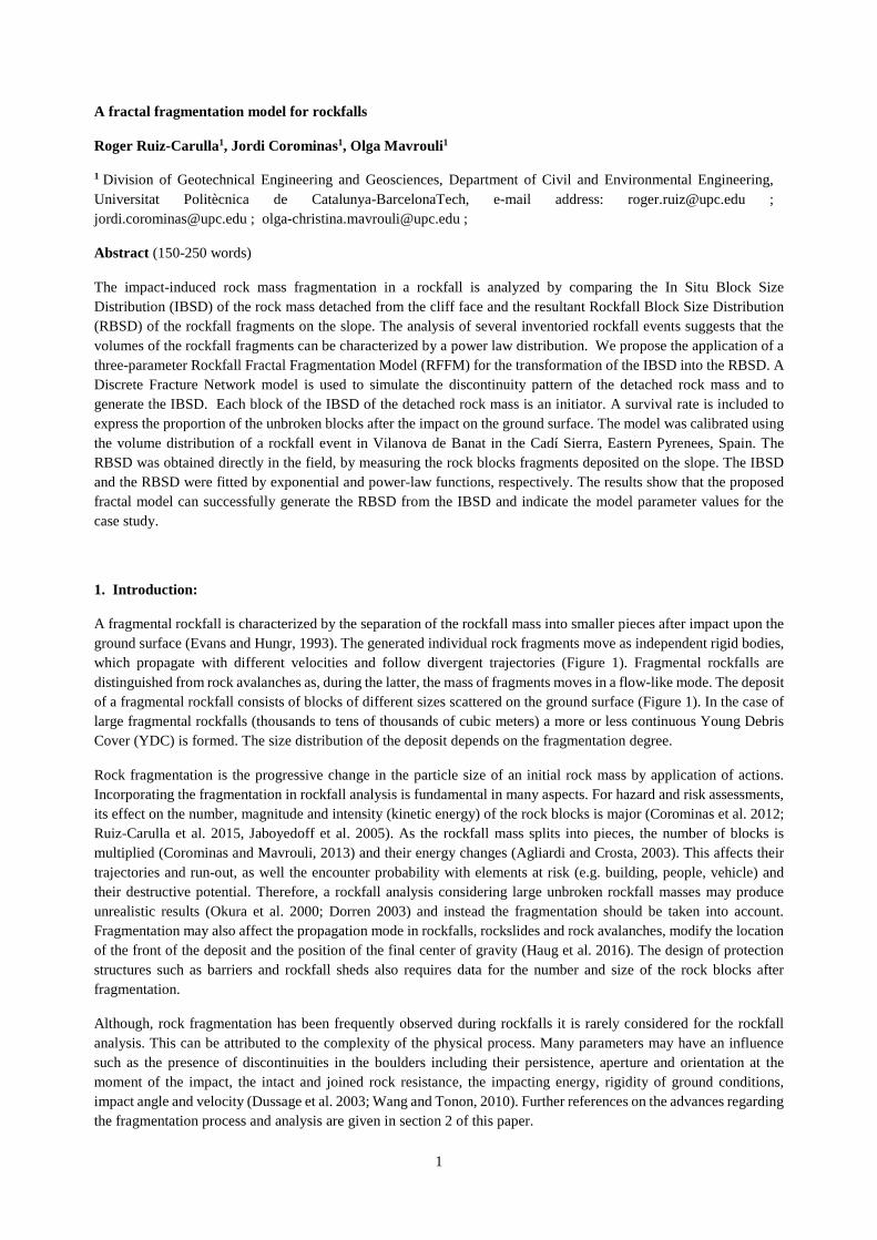
A fragmental rockfall is characterized by the separation of the rockfall mass into smaller pieces after impact upon the ground surface (Evans and Hungr, 1993). The generated individual rock fragments move as independent rigid bodies, which propagate with different velocities and follow divergent trajectories (Figure 1). Fragmental rockfalls are distinguished from rock avalanches as, during the latter, the mass of fragments moves in a flow-like mode. The deposit of a fragmental rockfall consists of blocks of different sizes scattered on the ground surface (Figure 1). In the case of large fragmental rockfalls (thousands to tens of thousands of cubic meters) a more or less continuous Young Debris Cover (YDC) is formed. The size distribution of the deposit depends on the fragmentation degree.
Rock fragmentation is the progressive change in the particle size of an initial rock mass by application of actions. Incorporating the fragmentation in rockfall analysis is fundamental in many aspects. For hazard and risk assessments, its effect on the number, magnitude and intensity (kinetic energy) of the rock blocks is major (Corominas et al. 2012; Ruiz-Carulla et al. 2015, Jaboyedoff et al. 2005). As the rockfall mass splits into pieces, the number of blocks is multiplied (Corominas and Mavrouli, 2013) and their energy changes (Agliardi and Crosta, 2003). This affects their trajectories and run-out, as well the encounter probability with elements at risk (e.g. building, people, vehicle) and their destructive potential. Therefore, a rockfall analysis considering large unbroken rockfall masses may produce unrealistic results (Okura et al. 2000; Dorren 2003) and instead the fragmentation should be taken into account. Fragmentation may also affect the propagation mode in rockfalls, rockslides and rock avalanches, modify the location of the front of the deposit and the position of the final center of gravity (Haug et al. 2016). The design of protection structures such as barriers and rockfall sheds also requires data for the number and size of the rock blocks after fragmentation.
Although, rock fragmentation has been frequently observed during rockfalls it is rarely considered for the rockfall analysis. This can be attributed to the complexity of the physical process. Many parameters may have an influence such as the presence of discontinuities in the boulders including their persistence, aperture and orientation at the moment of the impact, the intact and joined rock resistance, the impacting energy, rigidity of ground conditions, impact angle and velocity (Dussage et al. 2003; Wang and Tonon, 2010). Further references on the advances regarding the fragmentation process and analysis are given in section 2 of this paper.
2
Important contributions on the analysis of the rock fragmentation come from the field of blast design and rock avalanche analysis. To the knowledge of the authors, there are almost no rockfall kinematic models to simulate the fragmentation of the rock mass in the case of fragmental rockfalls. An exception is the model incorporated at the trajectory analysis software Hy-Stone (Wang, 2009), which applies a trained neural network to determine the mass and velocities of the fragments right after the impact.
This work aims to contribute to the modeling of the fragmentation of fragmental rockfalls, through the proposal of a three-parameter rockfall fractal fragmentation model, RFFM (section 3). The model is based on the assumption that the fragmentation can be considered as a transformation from the state with the In Situ Block Size Distribution (IBSD) at the cliff face (Lu and Latham, 1999) and the resultant Rockfall Block Size Distribution (RBSD) (Hantz, 2014; Ruiz-Carulla et al. 2015). This assumption is supported by the relationship between the intact rock properties and discontinuity structure of the rock mass, with the fragmentation degree and has been proved efficient for the characterization of the blastability of rocks (Lu, 1997). The proposed transition model from the IBSD to the RBSD is a three-parameter fractal model, based on that of Perfect (1997), where the resulting number-size distribution of fragments depends on the probability of failure, P(b); a survival rate, Sr; and a scaling factor, b.
Using field-obtained data from a large rockfall event that occurred in 2011 in Vilanova de Banat in the Cadí Sierra, Eastern Pyrenees, Spain, we explore the applicability of the proposed fragmentation model (section 4). We investigate the potential for calibration of the three parameters that are involved in the calculation of the RBSD using the proposed model, to fit the observed deposits.
Section 5 discusses the efficiency of the proposed model and the main controlling factors. It also casts a light on the points to focus on, for developing and advancing the model with a view to general application.
3
Fig. 1. Fragmental rockfall at Gurp, Central Pyrenees, Spain. A Young Debris Cover (YDC) is formed just below the rockfall source (purple polygon). Four large individual blocks (blue circles) followed both independent and divergent trajectories after the impact on the ground.
2. Rock Fragmentation
Rock fragmentation is a topic that has been addressed in a variety of scientific disciplines, such as in structural geology interested in the fracture pattern of rocks as the result of the tectonic activity (Molnar et al. 2007; Sammis and King, 2007); in fracture mechanics for the analysis of the response of cracks to both static and dynamic loading (Atkinson, 1987); in the assessment of the performance of the drilling equipment, mechanical excavators, tunnel boring machines (TBM), and for the consumption of disc cutters (Bakar et al. 2014); and in the mining industry, interested in the size distribution of muck piles after blasting and on the subsequent crushing and grinding (Aler et al. 1996; Morin et al. 2006; Kulatilake et al. 2010; Sanchidrián et al. 2014). At rock mass instabilities the fragmentation of the detached rock mass has been acknowledged by several researchers either for rockfalls (Dussauge 2003, Giacomini et al. 2009, Wang and Tonon 2010, Agliardi et al. 2009, Crosta et al. 2015) or for rock avalanches (Locat et al. 2006; Crosta et al. 2007; Davies et al. 1999; Hewitt, 1998, 1999; Hermanns et al. 2006; McSaveney and Davis, 2007; Weidinger et al. 2014).
Different types of mechanisms are invoked to explain the progressive change in grain size by application of actions. Crushing, grinding, comminution, fragmentation and dynamic fragmentation are the mechanisms usually quoted (Crosta et al. 2007). Fragmentation can occur as a result of dynamic crack propagation during compressive or tensile loading (dynamic fragmentation) or due to stress waves and their reflection during impact loading (ballistic fragmentation).
Davies et al. (1999) introduced the term fragmentation to describe the breaking of rocks into pieces smaller than those defined by the joint system of the parent rock mass. Nevertheless, for the purposes of this paper, fragmentation is used as a generic and inclusive term, meaning the division of an initial rock block or rock mass caused by either the breakage of the rock pieces, the disaggregation of joint-determined blocks, or both (Ruiz-Carulla et al. 2015). The breakage takes place under stresses that exceed the strength of the intact rock, resulting into new fractures.
2.1 Characterizing the fragmentation degree
The characterization of the rock fragmentations involves the measuring of the block size of the fragments. This is commonly performed either manually or by means of image analysis, the latter considering different assumptions for the extraction of block volumes from the image data (Locat et al. 2006, Crosta et al. 2007).
A range of descriptors can be used for the fragment size characterization. The d50 diameter or the mean size before and after the fragmentation are frequently used. In mine blasting, Kuznetsov (1973) associated the latter with the explosive energy and powder factors. Locat et al. (2006) also determined the degree of fragmentation for rock avalanches, by comparing the mean diameters of the blocks within the intact rock mass and the deposited fragments. Cunningham (1983 & 1987) further introduced a uniformity index “n”, depending on blast characteristics to describe the block size variation. Having obtained the mean size and the uniformity coefficient, statistical distributions can be fitted to the sizes of the fragmented blocks. The Rosin-Ramler model (Latham et al. 2006, Morin et al. 2006, Gheibie et al. 2009, Kulatilake et al. 2010 and Hudaverdi et al. 2010) is one of the most commonly used in rock blast fragmentation. Alternatively, if data are available, the characterization can be realized based on the block size distribution BSD of the entire fragmented deposit (Hardin, 1985). The BSD is typically represented as a grain size curve, in terms of percentage of material passing a certain size in a length unit as millimeters or meters, typically with 3 or 4 orders of magnitude of sizes.
The observation of different BSD has indicated that the fragments size follows a fractal distribution or power law (Turcotte 1986 & 1992, Poulton et al. 1990, Crum 1990, Hartmann 1969, Xu et al. 2016, and Peng et al. 2009. The power-law gradient is variable and it increases with the intensity of the fragmentation process (Hartmann 1969). Turcotte (1986) added that the fragmentation is often a scale invariant process, and the preexisting zones or planes of
4
weakness where failure occurs exist on all scales. Crosta et al. (2007) collecting data for the deposit of a rock avalanche indicated that its size distribution is characterized by a fractal dimension that was found consistent with other rock avalanche deposits (Dunning, 2006). Perfect (1997) discussed the use of the fractal theory and presented alternative models to analyze fragmentation in rock and soils.
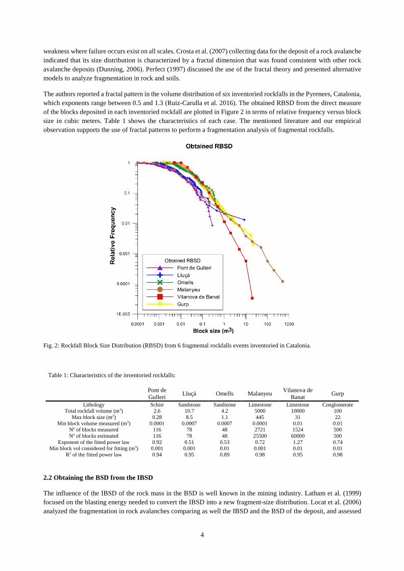
The authors reported a fractal pattern in the volume distribution of six inventoried rockfalls in the Pyrenees, Catalonia, which exponents range between 0.5 and 1.3 (Ruiz-Carulla et al. 2016). The obtained RBSD from the direct measure of the blocks deposited in each inventoried rockfall are plotted in Figure 2 in terms of relative frequency versus block size in cubic meters. Table 1 shows the characteristics of each case. The mentioned literature and our empirical observation supports the use of fractal patterns to perform a fragmentation analysis of fragmental rockfalls.
Fig. 2: Rockfall Block Size Distribution (RBSD) from 6 fragmental rockfalls events inventoried in Catalonia.
Table 1: Characteristics of the inventoried rockfalls:
Pont de Gulleri Lluçà Omells Malanyeu Vilanova de
Banat Gurp
Lithology Schist Sandstone Sandstone Limestone Limestone Conglomerate Total rockfall volume (m3) 2.6 10.7 4.2 5000 10000 100
Max block size (m3) 0.28 8.5 1.1 445 31 22 Min block volume measured (m3) 0.0001 0.0007 0.0007 0.0001 0.01 0.01
Nº of blocks measured 116 78 48 2721 1524 500 Nº of blocks estimated 116 78 48 25500 60000 500
Exponent of the fitted power law 0.92 0.51 0.53 0.72 1.27 0.74 Min block vol considered for fitting (m3) 0.001 0.001 0.01 0.001 0.01 0.01
R2 of the fitted power law 0.94 0.95 0.89 0.98 0.95 0.98
2.2 Obtaining the BSD from the IBSD The influence of the IBSD of the rock mass in the BSD is well known in the mining industry. Latham et al. (1999) focused on the blasting energy needed to convert the IBSD into a new fragment-size distribution. Locat et al. (2006) analyzed the fragmentation in rock avalanches comparing as well the IBSD and the BSD of the deposit, and assessed
5
the equivalent energy for the generation of the latter. To determine fragment sizes produced during a dynamic event, Grady (1982) and Grady and Kipp (1987) adopted an energy approach to the dynamic loading regime in which a balance between local kinetic energy and fracture energy is made. Lu (1997) proposed models for the transition of the size distribution of the initial rock mass to the size distribution of the fragments after blasting. Alternative approaches include the use of Rock Engineering Systems (RES) to study the influence of each controlling parameter of the fragmentation phenomenon by blasting and predict the resultant fragment size distribution (Faramarzi et al. 2013), multivariate analysis (Aler et al. 1996, Chakraborty et al. 2004 and Hudaverdi et al. 2010), Monte Carlo simulations (Morin and Ficarazzo, 2006) or neural network and artificial intelligence methods (Kutilake et al. 2010, Monjezi et al. 2009, Saavedra et al. 2006).
There is a scarcity of models for the prediction of fragmentation in the case of rock instabilities. Viero et al. (2012) carried out a mass balance of a rockfall case. They calculated that 80% of the material was converted in a cloud of dust. The real scale tests of Giacomini et al. (2009) and Gili et al. (2016) for fragmental rockfalls indicate the complexity in predicting the size distribution of the fragments based on impact energy thresholds. Wang & Tonon (2010) used a Discrete Element Method, DEM, code to simulate impact-induced rock fragmentation in rockfall analysis, and developed a trained neural network code that was integrated into the HY-STONE trajectory software (Crosta & Agliardi 2003). Bowman et al. (2014) studied the effect of the IBSD on the fragmentation and the runout of collapsed chalk cliffs. They performed several laboratory tests using different block assemblages and their findings for the amount of fragmentation showed consistency with use of Hardin (1985) breakage parameters for the definition of how much fragmentation has taken place during a breakage event related with the total runout of the rock mass. Charrière et al. (2015) also presented a model to calculate the successive block size distribution after fragmentation during a rock slide, which describes the breaking of a cubic block into two fragments with a random volume ratio, and in their turn their successive breaking in two more fragments each, for a chosen number of cycles. Further work is needed to develop transition models from the IBSD to the RBSD for fragmental rockfalls.
3. A Rockfall Fractal Fragmentation Model
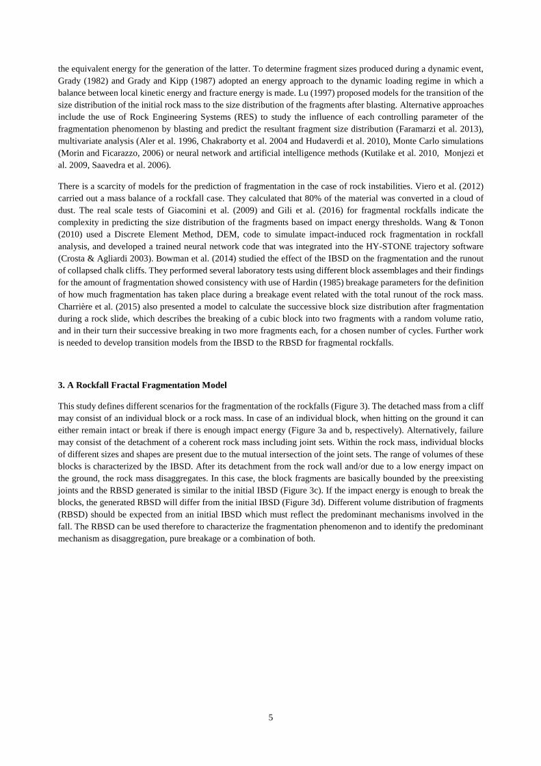
This study defines different scenarios for the fragmentation of the rockfalls (Figure 3). The detached mass from a cliff may consist of an individual block or a rock mass. In case of an individual block, when hitting on the ground it can either remain intact or break if there is enough impact energy (Figure 3a and b, respectively). Alternatively, failure may consist of the detachment of a coherent rock mass including joint sets. Within the rock mass, individual blocks of different sizes and shapes are present due to the mutual intersection of the joint sets. The range of volumes of these blocks is characterized by the IBSD. After its detachment from the rock wall and/or due to a low energy impact on the ground, the rock mass disaggregates. In this case, the block fragments are basically bounded by the preexisting joints and the RBSD generated is similar to the initial IBSD (Figure 3c). If the impact energy is enough to break the blocks, the generated RBSD will differ from the initial IBSD (Figure 3d). Different volume distribution of fragments (RBSD) should be expected from an initial IBSD which must reflect the predominant mechanisms involved in the fall. The RBSD can be used therefore to characterize the fragmentation phenomenon and to identify the predominant mechanism as disaggregation, pure breakage or a combination of both.
6
Fig. 3: Considered mechanisms in the fragmentation of falling rock blocks and rock masses. Conceptual schemes of changes in the block size distribution in the case of fragmentation by: a) lack of breakage of a single block; b) Breakage of a single block; c) Disaggregation of the rock mass through the preexisting joints; c) Disaggregation and breakage of the detached rock mass.
We proposed a Rockfall Fractal Fragmentation model RFFM that can express the aforementioned scenarios. In this model, the fragmentation of the rock mass initiates with the disaggregation of the rock mass along preexisting discontinuities and continues with the breakage of the rock blocks generating new fresh faces. Based on this, we consider the disaggregation of the mass, as controlled by the joint pattern, the first step for the fragmentation.
The RFFM proposed is based on the generic fractal fragmentation model of Perfect (1997). The model uses an initiator, which is either a single block or the individual blocks forming a rock mass. According to the model, if breakage does not takes place the initial volume distribution is preserved (Figure 3a and 3c). If the impact energy is high enough, the individual blocks will break either all of them or a percentage only (Figure 3b and 3d). Each broken block will produce a new distribution of fragments. The model is used to generate a RBSD from an initial IBSD. The fragmentation is assumed as scale-invariant, although the model may also perform as scale-variant.
The RFFM considers a cubic block of unit length that breaks into smaller pieces following a power law. Fractals are hierarchical, often highly irregular, geometric systems generated using iterative algorithms with relatively simple scaling rules (Mandelbrot, 1982). The size distribution of elements in a fractal system is given by (Eq.1):
7
(1/ ) 1/ ; 0,1, 2...Di iN b k b i
− = = ∞ Eq. 1
Where N(1/bi) is the total number of fragments at the ith level of hierarchy; k is the number of initiators of unit length; b is a scaling factor >1, that define the geometric proportion between the original block and the generated blocks; and D is the fractal dimension. N is rounded to the lower nearest integer.
The actual number of fragments produced depends on the probability of failure at the ith level, P(1/bi), which is defined as:
1(1/ ) / (1/ )(1/ ) ; 1
(1/ ) / (1/ )
j ii
i j i
N b N bP b n j i
N b N b
+ = = +
Eq. 2
and then 3(1/ ) /i
iP b n b= Eq. 3
Where ni is the number of fragments generated in the ith level. P(1/bi) is the proportion of block that breaks. The P(1/bi) can be physically related to subunit interfaces and their boundary strength, like in the case of fractured rocks, these interfaces represent preexisting planes of weakness, like anisotropy or non-persistent joints (Perfect, 1997). If the probability of failure is scale-invariant P(1/bi) = P(1/bi+1), it can be expressed as:
3(1/ )i DfP b b −= Eq. 4
or [ ]
[ ]log (1/ )
3log
if
P bD
b= + Eq. 5
Where Df is the fragmentation fractal dimension. The range for the probability of failure is b-3<P(1/bi)<1. When P(1/bi)=1 and Df=3 the whole block is fragmented, while for P(1/bi) ≤ b-3 the block remains unbroken.
The scale-invariant case is the simplest version of the fractal fragmentation model, where the parameters to be calibrated are the scaling factor b and the probability of failure P(1/bi). Looking for the physical interpretation of the probability of failure, if the block impact energy on the ground is low, the probability of failure is almost b-3, and in the opposite scenario, if the block impacts energy is high, the probability of failure is close to 1.
An example of how the model works is presented in the Figure 4. A simple cubic block is considered as the initiator (original block). Defining the geometric factor as b=2 the original block contains 8 possible breakables blocks. The probability of failure 1/8, defines the threshold for new block generation. For values of P(1/bi) below 1/8, the block will remain unbroken. For values just above 1/8, new blocks will be generated. The example shows the cases of: P(1/bi)=2/8=0.25, where 2 blocks are generated; P(1/bi)=3/8 where 3 blocks are generated and the case where P(1/bi)=4/8=0.5 where 4 blocks are generated. P(1/bi) can take values up to 8/8 or 1, where the whole original block will be fragmented generating 8 new blocks. The number of new blocks generated is a natural number. The example shows that the same generation rules over the blocks apply for successive iterations. This example is scale-invariant, where P(1/bi)= P(1/bi+1), then, P(1/b1)= P(1/b2).
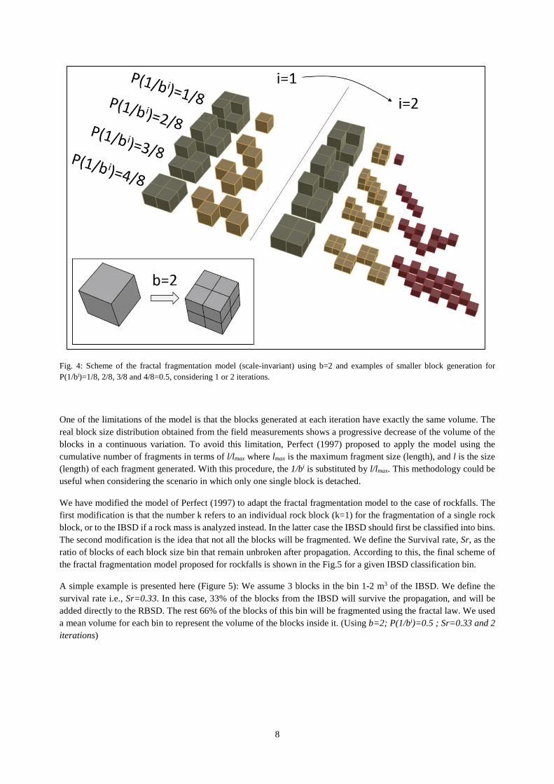
8
Fig. 4: Scheme of the fractal fragmentation model (scale-invariant) using b=2 and examples of smaller block generation for P(1/bi)=1/8, 2/8, 3/8 and 4/8=0.5, considering 1 or 2 iterations.
One of the limitations of the model is that the blocks generated at each iteration have exactly the same volume. The real block size distribution obtained from the field measurements shows a progressive decrease of the volume of the blocks in a continuous variation. To avoid this limitation, Perfect (1997) proposed to apply the model using the cumulative number of fragments in terms of l/lmax where lmax is the maximum fragment size (length), and l is the size (length) of each fragment generated. With this procedure, the 1/bi is substituted by l/lmax. This methodology could be useful when considering the scenario in which only one single block is detached.
We have modified the model of Perfect (1997) to adapt the fractal fragmentation model to the case of rockfalls. The first modification is that the number k refers to an individual rock block (k=1) for the fragmentation of a single rock block, or to the IBSD if a rock mass is analyzed instead. In the latter case the IBSD should first be classified into bins. The second modification is the idea that not all the blocks will be fragmented. We define the Survival rate, Sr, as the ratio of blocks of each block size bin that remain unbroken after propagation. According to this, the final scheme of the fractal fragmentation model proposed for rockfalls is shown in the Fig.5 for a given IBSD classification bin.
A simple example is presented here (Figure 5): We assume 3 blocks in the bin 1-2 m3 of the IBSD. We define the survival rate i.e., Sr=0.33. In this case, 33% of the blocks from the IBSD will survive the propagation, and will be added directly to the RBSD. The rest 66% of the blocks of this bin will be fragmented using the fractal law. We used a mean volume for each bin to represent the volume of the blocks inside it. (Using b=2; P(1/bi)=0.5 ; Sr=0.33 and 2 iterations)

9
Fig. 5: Scheme of the fractal fragmentation model applied over a bin 1-2 m3 with 3 blocks (average size 1.5m3) from the IBSD with a survival rate Sr=0.33, probability of failure P(1/bi)=0.5, scaling factor b=2 and using 2 iterations.
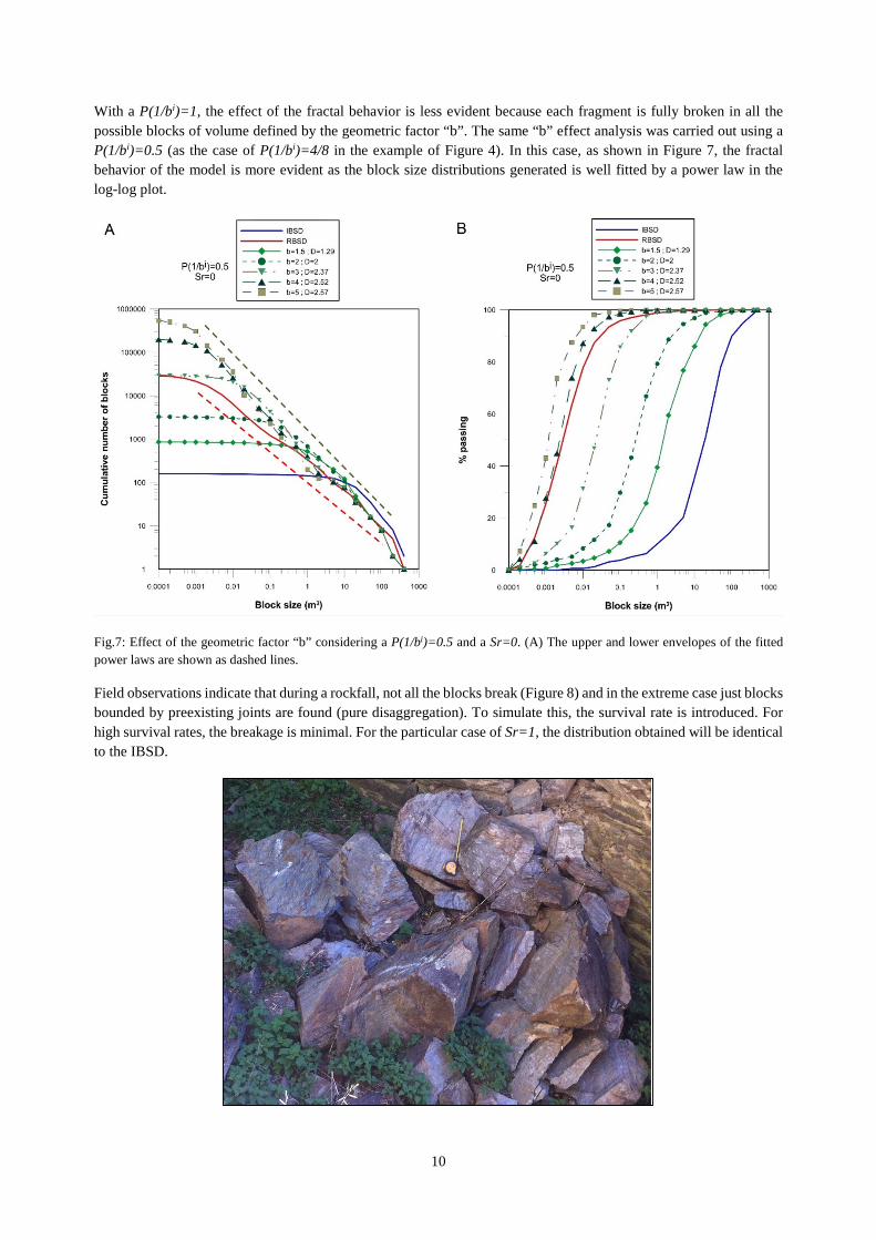
The geometric factor “b” controls the change of the average size. The number of blocks increases when the geometric factor “b” increases, allowing the generation of a larger number of fragments with two or three orders of magnitude smaller than the original blocks (Figure 6 A), also due to the use of two iterations. When “b” increases, the d50 (median) of the generated block size distributions decreases, as Figure 6 shows, (B plot in terms of % of material passing versus block size in cubic meters). The comparison of the geometric factor influence shown in Figure 6 is realized using two iterations, and considering the P(1/bi)=1, that implies a D=3, and a Sr=0.
Fig.6: Effect of the geometric factor b considering a P(1/bi)=1, that implies a D=3, and a Sr=0. Notice that the increase of the b-factor generates the increase of the number of blocks (A) and the reduction of the d50 size (B).
10
With a P(1/bi)=1, the effect of the fractal behavior is less evident because each fragment is fully broken in all the possible blocks of volume defined by the geometric factor “b”. The same “b” effect analysis was carried out using a P(1/bi)=0.5 (as the case of P(1/bi)=4/8 in the example of Figure 4). In this case, as shown in Figure 7, the fractal behavior of the model is more evident as the block size distributions generated is well fitted by a power law in the log-log plot.
Fig.7: Effect of the geometric factor “b” considering a P(1/bi)=0.5 and a Sr=0. (A) The upper and lower envelopes of the fitted power laws are shown as dashed lines.
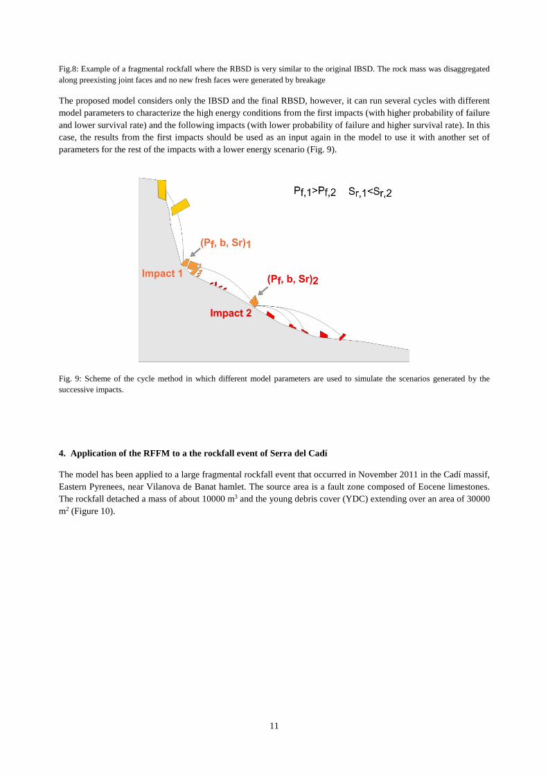
Field observations indicate that during a rockfall, not all the blocks break (Figure 8) and in the extreme case just blocks bounded by preexisting joints are found (pure disaggregation). To simulate this, the survival rate is introduced. For high survival rates, the breakage is minimal. For the particular case of Sr=1, the distribution obtained will be identical to the IBSD.
11
Fig.8: Example of a fragmental rockfall where the RBSD is very similar to the original IBSD. The rock mass was disaggregated along preexisting joint faces and no new fresh faces were generated by breakage
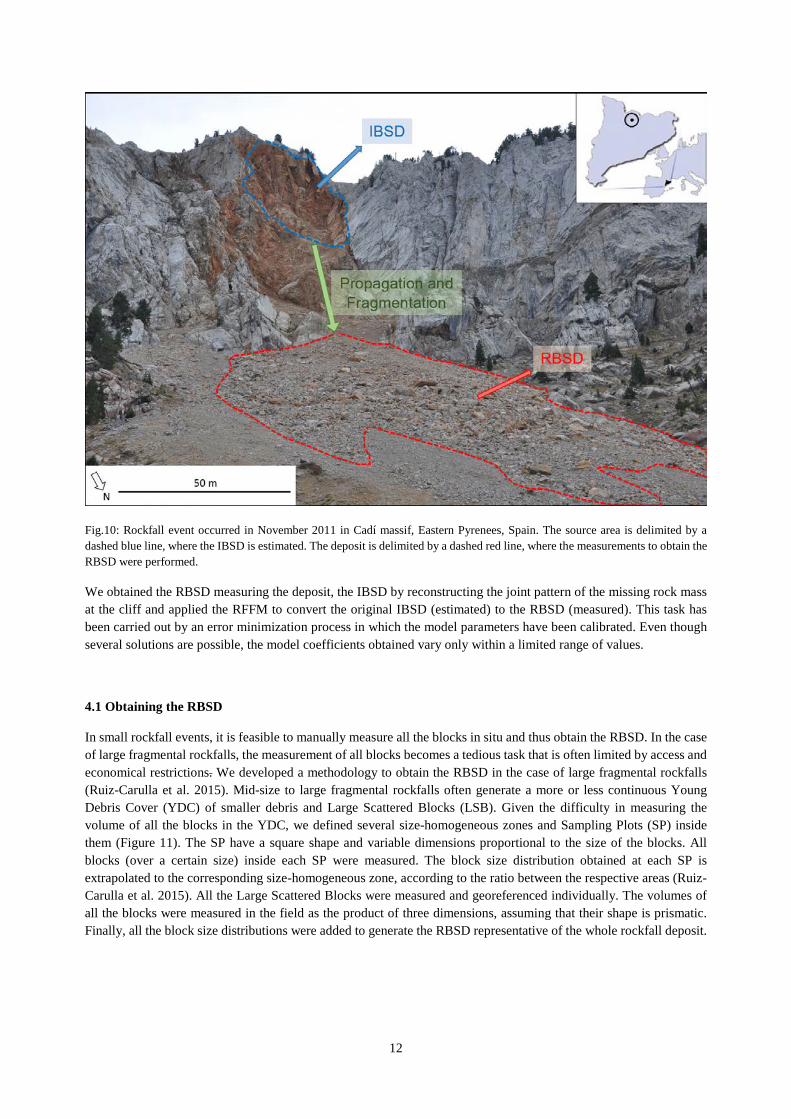
The proposed model considers only the IBSD and the final RBSD, however, it can run several cycles with different model parameters to characterize the high energy conditions from the first impacts (with higher probability of failure and lower survival rate) and the following impacts (with lower probability of failure and higher survival rate). In this case, the results from the first impacts should be used as an input again in the model to use it with another set of parameters for the rest of the impacts with a lower energy scenario (Fig. 9).
Fig. 9: Scheme of the cycle method in which different model parameters are used to simulate the scenarios generated by the successive impacts.
4. Application of the RFFM to a the rockfall event of Serra del Cadí
The model has been applied to a large fragmental rockfall event that occurred in November 2011 in the Cadí massif, Eastern Pyrenees, near Vilanova de Banat hamlet. The source area is a fault zone composed of Eocene limestones. The rockfall detached a mass of about 10000 m3 and the young debris cover (YDC) extending over an area of 30000 m2 (Figure 10).
12
Fig.10: Rockfall event occurred in November 2011 in Cadí massif, Eastern Pyrenees, Spain. The source area is delimited by a dashed blue line, where the IBSD is estimated. The deposit is delimited by a dashed red line, where the measurements to obtain the RBSD were performed.
We obtained the RBSD measuring the deposit, the IBSD by reconstructing the joint pattern of the missing rock mass at the cliff and applied the RFFM to convert the original IBSD (estimated) to the RBSD (measured). This task has been carried out by an error minimization process in which the model parameters have been calibrated. Even though several solutions are possible, the model coefficients obtained vary only within a limited range of values.
4.1 Obtaining the RBSD
In small rockfall events, it is feasible to manually measure all the blocks in situ and thus obtain the RBSD. In the case of large fragmental rockfalls, the measurement of all blocks becomes a tedious task that is often limited by access and economical restrictions. We developed a methodology to obtain the RBSD in the case of large fragmental rockfalls (Ruiz-Carulla et al. 2015). Mid-size to large fragmental rockfalls often generate a more or less continuous Young Debris Cover (YDC) of smaller debris and Large Scattered Blocks (LSB). Given the difficulty in measuring the volume of all the blocks in the YDC, we defined several size-homogeneous zones and Sampling Plots (SP) inside them (Figure 11). The SP have a square shape and variable dimensions proportional to the size of the blocks. All blocks (over a certain size) inside each SP were measured. The block size distribution obtained at each SP is extrapolated to the corresponding size-homogeneous zone, according to the ratio between the respective areas (Ruiz-Carulla et al. 2015). All the Large Scattered Blocks were measured and georeferenced individually. The volumes of all the blocks were measured in the field as the product of three dimensions, assuming that their shape is prismatic. Finally, all the block size distributions were added to generate the RBSD representative of the whole rockfall deposit.
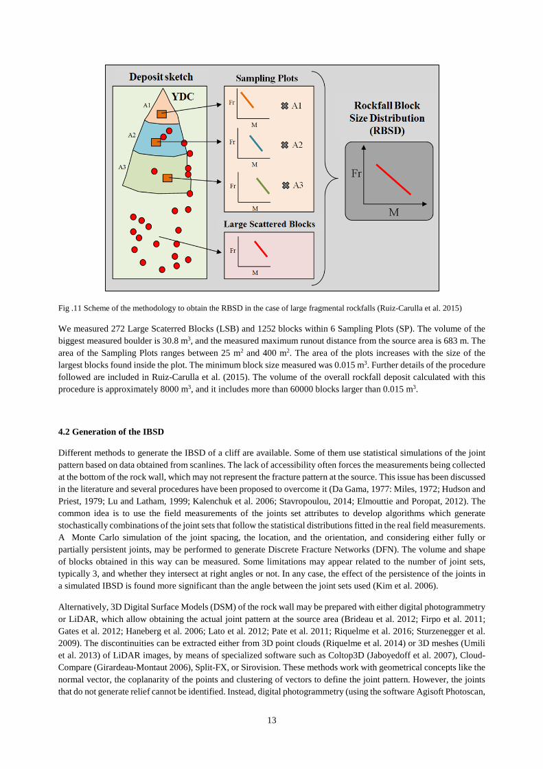
13
Fig .11 Scheme of the methodology to obtain the RBSD in the case of large fragmental rockfalls (Ruiz-Carulla et al. 2015)
We measured 272 Large Scaterred Blocks (LSB) and 1252 blocks within 6 Sampling Plots (SP). The volume of the biggest measured boulder is 30.8 m3, and the measured maximum runout distance from the source area is 683 m. The area of the Sampling Plots ranges between 25 m2 and 400 m2. The area of the plots increases with the size of the largest blocks found inside the plot. The minimum block size measured was 0.015 m3. Further details of the procedure followed are included in Ruiz-Carulla et al. (2015). The volume of the overall rockfall deposit calculated with this procedure is approximately 8000 m3, and it includes more than 60000 blocks larger than 0.015 m3.
4.2 Generation of the IBSD
Different methods to generate the IBSD of a cliff are available. Some of them use statistical simulations of the joint pattern based on data obtained from scanlines. The lack of accessibility often forces the measurements being collected at the bottom of the rock wall, which may not represent the fracture pattern at the source. This issue has been discussed in the literature and several procedures have been proposed to overcome it (Da Gama, 1977: Miles, 1972; Hudson and Priest, 1979; Lu and Latham, 1999; Kalenchuk et al. 2006; Stavropoulou, 2014; Elmouttie and Poropat, 2012). The common idea is to use the field measurements of the joints set attributes to develop algorithms which generate stochastically combinations of the joint sets that follow the statistical distributions fitted in the real field measurements. A Monte Carlo simulation of the joint spacing, the location, and the orientation, and considering either fully or partially persistent joints, may be performed to generate Discrete Fracture Networks (DFN). The volume and shape of blocks obtained in this way can be measured. Some limitations may appear related to the number of joint sets, typically 3, and whether they intersect at right angles or not. In any case, the effect of the persistence of the joints in a simulated IBSD is found more significant than the angle between the joint sets used (Kim et al. 2006).
Alternatively, 3D Digital Surface Models (DSM) of the rock wall may be prepared with either digital photogrammetry or LiDAR, which allow obtaining the actual joint pattern at the source area (Brideau et al. 2012; Firpo et al. 2011; Gates et al. 2012; Haneberg et al. 2006; Lato et al. 2012; Pate et al. 2011; Riquelme et al. 2016; Sturzenegger et al. 2009). The discontinuities can be extracted either from 3D point clouds (Riquelme et al. 2014) or 3D meshes (Umili et al. 2013) of LiDAR images, by means of specialized software such as Coltop3D (Jaboyedoff et al. 2007), Cloud-Compare (Girardeau-Montaut 2006), Split-FX, or Sirovision. These methods work with geometrical concepts like the normal vector, the coplanarity of the points and clustering of vectors to define the joint pattern. However, the joints that do not generate relief cannot be identified. Instead, digital photogrammetry (using the software Agisoft Photoscan,
14
http://www.agisoft.com) generates DSM that have the geometrical information and also the texture, thus allowing the visual identification of traces of joints in a rock wall (Ferrero et al. 2011, Firpo et al. 2011, Haneberg et al. 2006, Gates and Haneberg 2012, Lato et al. 2012, Sturzenegger et al. 2009)
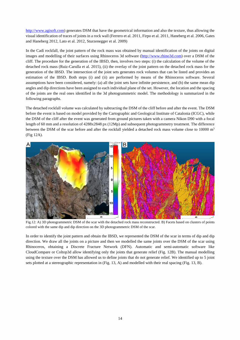
In the Cadí rockfall, the joint pattern of the rock mass was obtained by manual identification of the joints on digital images and modelling of their surfaces using Rhinoceros 3d software (http://www.rhino3d.com) over a DSM of the cliff. The procedure for the generation of the IBSD, then, involves two steps: (i) the calculation of the volume of the detached rock mass (Ruiz-Carulla et al. 2015), (ii) the overlay of the joint pattern on the detached rock mass for the generation of the IBSD. The intersection of the joint sets generates rock volumes that can be listed and provides an estimation of the IBSD. Both steps (i) and (ii) are performed by means of the Rhinoceros software. Several assumptions have been considered, namely: (a) all the joint sets have infinite persistence, and (b) the same mean dip angles and dip directions have been assigned to each individual plane of the set. However, the location and the spacing of the joints are the real ones identified in the 3d photogrammetric model. The methodology is summarized in the following paragraphs.
The detached rockfall volume was calculated by subtracting the DSM of the cliff before and after the event. The DSM before the event is based on model provided by the Cartographic and Geological Institute of Catalonia (ICGC), while the DSM of the cliff after the event was generated from ground pictures taken with a camera Nikon D90 with a focal length of 60 mm and a resolution of 4288x2848 px (12Mp) and subsequent photogrammetry treatment. The difference between the DSM of the scar before and after the rockfall yielded a detached rock mass volume close to 10000 m3
(Fig 12A).
Fig.12: A) 3D photogrammetric DSM of the scar with the detached rock mass reconstructed. B) Facets based on clusters of points colored with the same dip and dip direction on the 3D photogrammetric DSM of the scar.
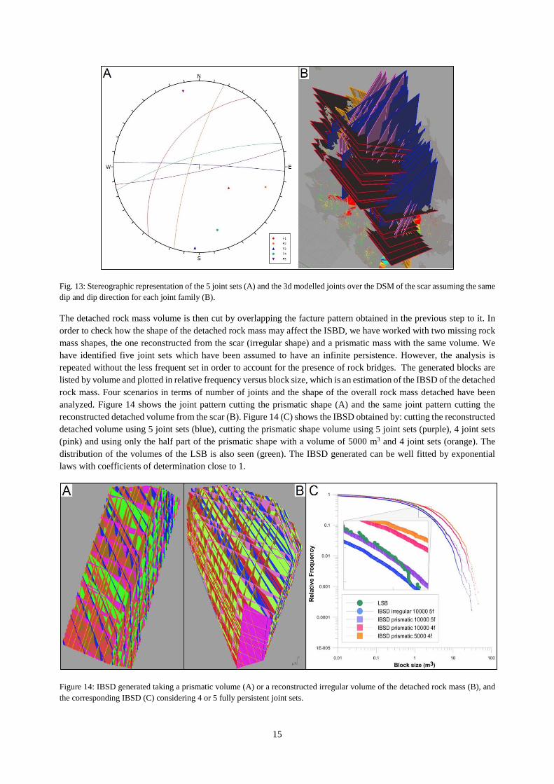
In order to identify the joint pattern and obtain the IBSD, we represented the DSM of the scar in terms of dip and dip direction. We draw all the joints on a picture and then we modelled the same joints over the DSM of the scar using Rhinoceros, obtaining a Discrete Fracture Network (DFN). Automatic and semi-automatic software like CloudCompare or Coltop3d allow identifying only the joints that generate relief (Fig. 12B). The manual modelling using the texture over the DSM has allowed us to define joints that do not generate relief. We identified up to 5 joint sets plotted at a stereographic representation in (Fig. 13, A) and modelled with their real spacing (Fig. 13, B).
15
Fig. 13: Stereographic representation of the 5 joint sets (A) and the 3d modelled joints over the DSM of the scar assuming the same dip and dip direction for each joint family (B).
The detached rock mass volume is then cut by overlapping the facture pattern obtained in the previous step to it. In order to check how the shape of the detached rock mass may affect the ISBD, we have worked with two missing rock mass shapes, the one reconstructed from the scar (irregular shape) and a prismatic mass with the same volume. We have identified five joint sets which have been assumed to have an infinite persistence. However, the analysis is repeated without the less frequent set in order to account for the presence of rock bridges. The generated blocks are listed by volume and plotted in relative frequency versus block size, which is an estimation of the IBSD of the detached rock mass. Four scenarios in terms of number of joints and the shape of the overall rock mass detached have been analyzed. Figure 14 shows the joint pattern cutting the prismatic shape (A) and the same joint pattern cutting the reconstructed detached volume from the scar (B). Figure 14 (C) shows the IBSD obtained by: cutting the reconstructed detached volume using 5 joint sets (blue), cutting the prismatic shape volume using 5 joint sets (purple), 4 joint sets (pink) and using only the half part of the prismatic shape with a volume of 5000 m3 and 4 joint sets (orange). The distribution of the volumes of the LSB is also seen (green). The IBSD generated can be well fitted by exponential laws with coefficients of determination close to 1.
Figure 14: IBSD generated taking a prismatic volume (A) or a reconstructed irregular volume of the detached rock mass (B), and the corresponding IBSD (C) considering 4 or 5 fully persistent joint sets.
16
4.3 Comparison of the IBSD and RBSD
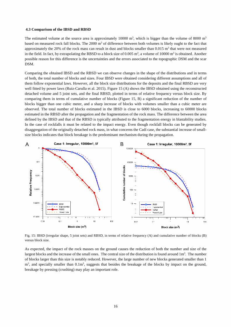
The estimated volume at the source area is approximately 10000 m3, which is bigger than the volume of 8000 m3
based on measured rock fall blocks. The 2000 m3 of difference between both volumes is likely ought to the fact that approximately the 20% of the rock mass can result in dust and blocks smaller than 0.015 m3 that were not measured in the field. In fact, by extrapolating the RBSD to a block size of 0.005 m3, a volume of 10000 m3 is obtained. Another possible reason for this difference is the uncertainties and the errors associated to the topographic DSM and the scar DSM.
Comparing the obtained IBSD and the RBSD we can observe changes in the shape of the distributions and in terms of both, the total number of blocks and sizes. Four IBSD were obtained considering different assumptions and all of them follow exponential laws. However, all the block size distributions for the deposits and the final RBSD are very well fitted by power laws (Ruiz-Carulla et al. 2015). Figure 15 (A) shows the IBSD obtained using the reconstructed detached volume and 5 joint sets, and the final RBSD, plotted in terms of relative frequency versus block size. By comparing them in terms of cumulative number of blocks (Figure 15, B) a significant reduction of the number of blocks bigger than one cubic meter, and a sharp increase of blocks with volumes smaller than a cubic meter are observed. The total number of blocks estimated in the IBSD is close to 6000 blocks, increasing to 60000 blocks estimated in the RBSD after the propagation and the fragmentation of the rock mass. The difference between the area defined by the IBSD and that of the RBSD is typically attributed to the fragmentation energy in blastability studies. In the case of rockfalls it must be related to the impact energy. Even though rockfall blocks can be generated by disaggregation of the originally detached rock mass, in what concerns the Cadí case, the substantial increase of small-size blocks indicates that block breakage is the predominant mechanism during the propagation.
Fig. 15: IBSD (irregular shape, 5 joint sets) and RBSD, in terms of relative frequency (A) and cumulative number of blocks (B) versus block size.
As expected, the impact of the rock masses on the ground causes the reduction of both the number and size of the largest blocks and the increase of the small ones. The central size of the distribution is found around 1m3. The number of blocks larger than this size is notably reduced. However, the large number of new blocks generated smaller than 1 m3, and specially smaller than 0.1m3, suggests that besides the breakage of the blocks by impact on the ground, breakage by pressing (crushing) may play an important role.
17
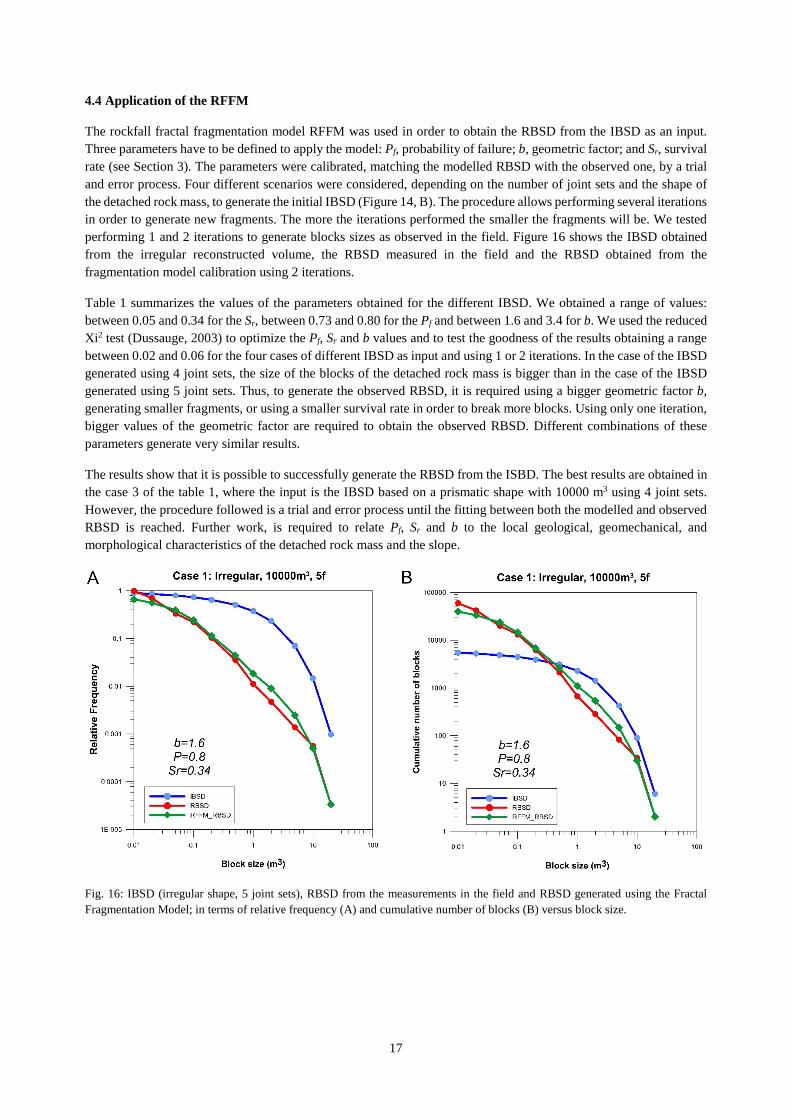
4.4 Application of the RFFM
The rockfall fractal fragmentation model RFFM was used in order to obtain the RBSD from the IBSD as an input. Three parameters have to be defined to apply the model: Pf, probability of failure; b, geometric factor; and Sr, survival rate (see Section 3). The parameters were calibrated, matching the modelled RBSD with the observed one, by a trial and error process. Four different scenarios were considered, depending on the number of joint sets and the shape of the detached rock mass, to generate the initial IBSD (Figure 14, B). The procedure allows performing several iterations in order to generate new fragments. The more the iterations performed the smaller the fragments will be. We tested performing 1 and 2 iterations to generate blocks sizes as observed in the field. Figure 16 shows the IBSD obtained from the irregular reconstructed volume, the RBSD measured in the field and the RBSD obtained from the fragmentation model calibration using 2 iterations.
Table 1 summarizes the values of the parameters obtained for the different IBSD. We obtained a range of values: between 0.05 and 0.34 for the Sr, between 0.73 and 0.80 for the Pf and between 1.6 and 3.4 for b. We used the reduced Xi2 test (Dussauge, 2003) to optimize the Pf, Sr and b values and to test the goodness of the results obtaining a range between 0.02 and 0.06 for the four cases of different IBSD as input and using 1 or 2 iterations. In the case of the IBSD generated using 4 joint sets, the size of the blocks of the detached rock mass is bigger than in the case of the IBSD generated using 5 joint sets. Thus, to generate the observed RBSD, it is required using a bigger geometric factor b, generating smaller fragments, or using a smaller survival rate in order to break more blocks. Using only one iteration, bigger values of the geometric factor are required to obtain the observed RBSD. Different combinations of these parameters generate very similar results.
The results show that it is possible to successfully generate the RBSD from the ISBD. The best results are obtained in the case 3 of the table 1, where the input is the IBSD based on a prismatic shape with 10000 m3 using 4 joint sets. However, the procedure followed is a trial and error process until the fitting between both the modelled and observed RBSD is reached. Further work, is required to relate Pf, Sr and b to the local geological, geomechanical, and morphological characteristics of the detached rock mass and the slope.
Fig. 16: IBSD (irregular shape, 5 joint sets), RBSD from the measurements in the field and RBSD generated using the Fractal Fragmentation Model; in terms of relative frequency (A) and cumulative number of blocks (B) versus block size.
18
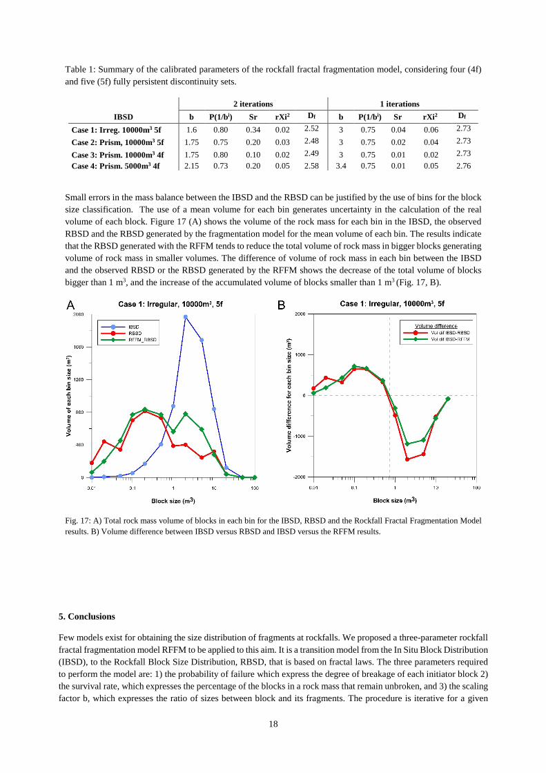
Table 1: Summary of the calibrated parameters of the rockfall fractal fragmentation model, considering four (4f) and five (5f) fully persistent discontinuity sets.
2 iterations 1 iterations IBSD b P(1/bi) Sr rXi2 Df b P(1/bi) Sr rXi2 Df
Case 1: Irreg. 10000m3 5f 1.6 0.80 0.34 0.02 2.52 3 0.75 0.04 0.06 2.73
Case 2: Prism, 10000m3 5f 1.75 0.75 0.20 0.03 2.48 3 0.75 0.02 0.04 2.73
Case 3: Prism. 10000m3 4f 1.75 0.80 0.10 0.02 2.49 3 0.75 0.01 0.02 2.73 Case 4: Prism. 5000m3 4f 2.15 0.73 0.20 0.05 2.58 3.4 0.75 0.01 0.05 2.76
Small errors in the mass balance between the IBSD and the RBSD can be justified by the use of bins for the block size classification. The use of a mean volume for each bin generates uncertainty in the calculation of the real volume of each block. Figure 17 (A) shows the volume of the rock mass for each bin in the IBSD, the observed RBSD and the RBSD generated by the fragmentation model for the mean volume of each bin. The results indicate that the RBSD generated with the RFFM tends to reduce the total volume of rock mass in bigger blocks generating volume of rock mass in smaller volumes. The difference of volume of rock mass in each bin between the IBSD and the observed RBSD or the RBSD generated by the RFFM shows the decrease of the total volume of blocks bigger than 1 m3, and the increase of the accumulated volume of blocks smaller than 1 m3 (Fig. 17, B).
Fig. 17: A) Total rock mass volume of blocks in each bin for the IBSD, RBSD and the Rockfall Fractal Fragmentation Model results. B) Volume difference between IBSD versus RBSD and IBSD versus the RFFM results.
5. Conclusions
Few models exist for obtaining the size distribution of fragments at rockfalls. We proposed a three-parameter rockfall fractal fragmentation model RFFM to be applied to this aim. It is a transition model from the In Situ Block Distribution (IBSD), to the Rockfall Block Size Distribution, RBSD, that is based on fractal laws. The three parameters required to perform the model are: 1) the probability of failure which express the degree of breakage of each initiator block 2) the survival rate, which expresses the percentage of the blocks in a rock mass that remain unbroken, and 3) the scaling factor b, which expresses the ratio of sizes between block and its fragments. The procedure is iterative for a given

19
number i of hierarchies. Successive iterations result in a progressively smaller fragment sizes. The fragmentation is assumed scale-invariant, although the model may also perform as scale-variant. For Sr=1, the RBSD reproduces the IBSD, as only disaggregation and no breakage takes place. The model allows the reproduction of two fragmentation mechanism defined as disaggregation and pure breakage.
An advantage of this model is that it is simple enough to be incorporated into rockfall trajectory analyses. Additionally, the proposed RFFM allows the possibility of considering different model parameters according to the energetic scenario of each impact. The minimum size of the deposit can be efficiently reproduced using proper number of iterations i.
At the proposed model, the mass balance is not fulfilled. This is due to the classification of the fragmented block sizes into bins, and the use of the lower, average and upper bin values for the calculation of the total volume after fragmentation. To overcome this problem it is possible to work with all the listed volumes from the IBSD avoiding the use of the classification in bins.
The application of the RFFM to the rockfall event of 2011 to the Sierra del Cadí, in the East Pyrenees, Spain, has shown that the model is efficient in providing with sufficient accuracy the RBSD, provided that the IBSD is known beforehand. The results of the model may vary depending on the assumptions made for the joint pattern at the rockfall source as well as the strength of the rock, the impact energy and the ground rigidity. The obtained ranges of values for the parameters were: between 0.05 and 0.34 for the Sr, between 0.73 and 0.80 for the Pf and between 1.6 and 3.4 for b. The application of the model to the case study of Sierra del Cadí has also shown that two iterations are sufficient for reproducing the block size distribution was observed in the field.
Despite of this performance, further work including more rockfall events, lithologies, heights of fall, ground surface rigidity and joint patterns, is needed before assigning beforehand values to the model parameters, in order to be able to use it as a forward predictive model.
Acknowledgments
The authors acknowledge the support of the Spanish Economy and Competitiveness Ministry to the Rockrisk research project (BIA2013-42582-P) and the support of the Ministry of Education to the first author (grant code FPU13/04252), and the support of the fellowship “Ayudas Fundación BBVA a Investigadores, Innovadores y Creadores Culturales” by the Foundation BBVA to the third author.
References
Agliardi F, Crosta G (2003) High resolution three-dimensional numerical modelling of rockfalls. International Journal of Rock Mechanics and Mining Sciences vol. 40, 4, pp. 455-471
Agliardi F, Crosta G, Frattini P (2009) Integrating rockfall risk assessment and countermeasure design by 3D modelling techniques Nat. Hazards Earth Syst. Sci., 9 , pp. 1059–1073 http://dx.doi.org/10.5194/nhess-9-1059-2009
Aler J, Du Mouza J, Arnould M (1996) Measurement of the Fragmentation Efficiency of Rock Mass Blasting and its Mining Applications. Int. J. Rock Mech. Min. Sci. & Geomech. Abstr., 33: 125-139
Atkinson BK (1987) Fracture mechanics of rock. Academic Press Inc, London. 534 pp
Bakar MZ, Gertsch LS, Rostami J (2014) Evaluation of Fragments from Disc Cutting of Dry and Saturated Sandstone. Rock Mech Rock Eng, 47:1891–1903
Bowman ET, Andrew Take W (2014) The Runout of Chalk Cliff Collapses in England and France — Case Studies and Physical Model Experiments.” Landslides, Volume 12 (2), pp: 225-239. doi: 10.1007/s10346-014-0472-2

20
Brideau M, Sturzenegger M, Stead D, Jaboyedoff M, Lawrence M, Roberts N, Ward B, Millard T, Clague J (2012) “Stability Analysis of the 2007 Chehalis Lake Landslide Based on Long-Range Terrestrial Photogrammetry and Airborne LiDAR Data.” Landslides 9: 75–91. doi:10.1007/s10346-011-0286-4.
Chakraborty AK, Raina AK, Ramulu M, Choudhury PB, Haldar A, Sahu P (2004) Parametric study to develop guidelines for blast fragmentation improvement in jointed and massive formations. Eng Geol, 73: 105–16.
Charrière M, Humair F, Froese C, Jaboyedoff M, Pedrazzini A, Longchamp C (2015) From the source are to the deposit: Collapse, fragmentation, and propagation of the Frank Slide. Geological Society of America Bulletin. doi: 10.1130/B31243.1
Corominas J, Mavrouli O, Santana D, Moya J (2012) Simplified approach for obtaining the block volume distribution of fragmental rockfalls. A: International Symposium on Landslides. "Landslides and Engineered Slopes". Banff: CRC Press. Taylor & Francies Group, 2013, p. 1159-1164.
Corominas, J, Mavrouli O (2013) Estimation quantitative du risque (QRA) pour les bâtiments induit par des éboulements rocheux: état des lieux. Mémoire Societé Vadoise des Sciences Naturelles, 25: 229-242
Crosta GB, Frattini P, Fusi F (2007) Fragmentation in the Val Pola rock avalanche, Italian Alps. Journal of Geophysical Research, 112: p. F01006
Crosta GB, Agliardi F, Frattini P, Lari S, Lollino G (2015) Key Issues in Rock Fall Modeling, Hazard and Risk Assessment for Rockfall Protection. Engineering Geology for Society and Territory, Volume 2, pp: 43-58. doi: 10.1007/978-3-319-09057-3_4
Crum SV (1990) Fractal concepts applied to bench-blast fragmentation. in: Proc. 3rd US Rock Mech. Symp. Rotterdam: Balkema, pp. 913-919
Cunningham CVB, (1983) The Kuz-Ram model for prediction of fragmentation from blasting. In: Proceedings of the First International Symposium on Rock Fragmentation by Blasting, 22–26 August , Lulea, Sweden, pp. 439–454
Cunningham CVB (1987) Fragmentation estimations and Kuz-Ram model – four years on. Proceedings of second International Symposium on rock fragmentation by blasting, Keystone, Colorado, p.475–87
Da Gama C D (1977) Computer model for block size analysis of jointed rock masses. In 15th APCOM symposium, Brisbane, Australia, pp 305-315
Davies TR, McSaveney MJ, Hodgson KA (1999) A fragmentation-spreading model for long-runout rock avalanches. Canadian Geotechnical Journal, 36: 1096-1110
Dussauge C, Grasso J, Helmstetter A (2003) Statistical Analysis of Rock Fall Volume Distributions: Implications for Rock fall Dynamics. Journal of Geophysical Research B 108 (B6) 2286, doi: 10.1029/2001JB000650
Dorren LKA (2003) A review of rockfall mechanics and modeling approaches. Progress in Physical Geography 27 (1): 69– 87
Dunning, S. A. (2006), The grain-size distribution of rock avalanche deposits in valley-confined settings, Ital. J. Eng. Geol. Environ., 1,117 – 121
Elmouttie MK, Poropat GV (2012). A Method to Estimate In Situ Block Size Distribution. Rock Mechanics and Rock Engineering, 45(3), 401–407. doi:10.1007/s00603-011-0175-0
Evans S, Hungr O (1993) The assessment of rockfall hazard at the base of talus slopes. Canadian Geotechnical Journal 30 :620-636

21
Faramarzi F, Mansouri H, Ebrahimi Farsangi MA (2013) A Rock Engineering Systems Based Model to Predict Rock Fragmentation by Blasting. International Journal of Rock Mechanics and Mining Sciences 60: 82–94. doi:10.1016/j.ijrmms.2012.12.045.
Ferrero AM, Migliazza M, Roncella R, Segalini A (2011) Rock cliffs hazard analysis based on remote geostructural surveys: The Campione del Garda case study (Lake Garda, Northern Italy). Geomorphology 125: pp 457-471
Firpo G, Salvini R, Francioni M, Ranjith P (2011) Use of Digital Terrestrial Photogrammetry in rocky slope stability analysis by Distinct Elements Numerical Methods. International Journal of rock Mechanics and Mining Sciences 48:1045-1054
Gates WCB, Haneberg WC (2012) Comparison of Standard Structural Mapping Results to 3-D Photogrammetric Model Results : Boundary Transformer Banks Rockfall. American Rock Mechanics Association 12: 368.
Gheibie S, Aghababaei H, Hoseinie S H, Pourrahimian Y (2009) Modified Kuz – Ram fragmentation model and its use at the Sungun Copper Mine. International Journal od Rock Mechanics & Mining Sciences 46: 967-973. doi:10.1016/j.ijrmms.2009.05.003
Giacomini A, Buzzi O, Renard B & Giani, G P (2009) Experimental studies on fragmentation of rock falls on impact with rock surfaces. Int J Rock Mech Min Sci 46:708–715
Gili JA, Ruiz-Carulla R, Matas G, Corominas J, Lantada N, Núñez MA, Mavrouli O, Buill F, Moya J, Prades A, Moreno S (2016) Experimental study on rockfall fragmentation: in situ test design and firsts results. International Symposium Landslides 2016 (ISL2016), pp 983-990, Napoli (Italia)
Girardeau-Montaut (2006) Detection de Changement sur des Données Géométriques 3D", D. PhD manuscript (french), Signal & Images Processing, Telecom Paris
Grady DE (1982) Local inertial effects in dynamic fragmentation, Journal of Applied Physics, 53: pp 322-5.
Grady DE, Kipp ME (1987) Dynamic fragmentation of rock. Fracture Mechanics of Rock, Atkinson, B.K. Ed., Academic Press, San Diego, California, 429-475.
Haneberg WC, Norrish NI, Findley DP (2006) Digital Outcrop Characterization for 3-D Structural Mapping and Rock Slope Design along Interstate 90 near Snoqualmie Pass, Washington.” Proceedings 57th Annual Highway Geology Symposium, 1–14.
Hantz D, Rossetti JP, Servant F, D'Amato J (2014) Etude de la distribution des blocs dans un éboulement pour l’évaluation de l’aléa. Proceedings of Rock Slope Stability 2014, Marrakesh, Morocco
Hardin BO (1985) Crushing of soil particles. J Geotech Eng 111(10):1177–1191
Hartmann W K (1969) Terrestrial, lunar and interplanetary rock fragmentation. Icarus 10 (2): 201–213. doi:10.1016/0019-1035(69)90022-0
Hermanns RL, Blikra LH, Naumann M, Nilsen B, Panthi KK, Stromeyer D, Longva O (2006) Examples of multiple rock-slope collapses from Köfels (Ötz valley, Austria) and western Norway. Eng. Geol. 83, 94–108
Haug ØT, Rosenau M, Leever K, Oncken O (2016) On the energy budgets of fragmenting rockfalls and rockslides: Insights from experiments, J. Geophys. Res. Earth Surface, 121, 1310–1327, doi:10.1002/2014JF003406.
Hewitt K, (1998) Catastrophic landslides and their effects on the Upper Indus streams, Karakoram Himalaya, northern Pakistan. Geomorphology 26, 47–80
Hewitt K, (1999) Quaternary moraines vs catastrophic rock avalanches in the Karakoram Himalaya, Northern Pakistan. Quat. Res. 51, 220–237

22
Hudaverdi T, Kuzu C, Fisne A (2010) Investigation of the blast fragmentation using the mean fragment size and fragmentation index. International Journal Rock Mechanics & Minning Science, Volume 56, pp: 136-145. http://dx.doi.org/10.1016/j.ijrmms.2012.07.028.
Hudson JA, Priest SD (1979) Discontinuities and rock mass geometry. International Journal Rock Mechanics Minning Science Geomech Abstr 16: 339-362
Jaboyedoff M, Dudt JP, Labiouse V (2005) An attempt to refine rockfall hazard zoning based on the kinetic energy, frequency and fragmentation degree. Natural Hazards and Earth System Sciences 5: 621–632
Jaboyedoff M, Metzger R, Oppikofer T, Couture R, Derron MH, Locat J, Turmel D (2007) New insight techniques to analyze rock-slope relief using DEM and 3D-imaging cloud points: COLTOP-3D software, in: Rock mechanics: Meeting Society’s challenges and demands, Proceedings of the 1st Canada – U.S. Rock Mechanics Symposium, edited by: Eberhardt, E., Stead, D., and Morrison, T., Vancouver, Canada, 27–31 May, Taylor & Francis, London, UK, 1, 61–68
Kalenchuk KS, Diederichs MS, McKinnon S (2006) Characterizing block geometry in jointed rockmasses. International Journal of Rock Mechanics and Mining Sciences 43: 1212-1225
Kim BH, Cai M, Kaiser PK, Yang HS (2006) Estimation of Block Sizes for Rock Masses with Non-persistent Joints. Rock Mechanics and Rock Engineering, 40(2), 169–192. doi:10.1007/s00603-006-0093-8
Kulatilake PSHW, Qiong W, Hudaverdi T, Kuzu C (2010) Mean particle size prediction in rock blast fragmentation using neural networks. Engineering Geology, 114: 298–311 doi:10.1016/j.enggeo.2010.05.008
Kuznetsov VM (1973). The mean diameter of fragments formed by blasting rock. Journal of Mining Science. 9: 144–148.
Latham J, Meulen J, Dupray S (2006) Prediction of fragmentation and yield curves with reference to armourstone production. Engineering Geology 87: 60–74 doi:10.1016/j.enggeo.2006.05.005
Latham J, and Ping Lu. 1999. Development of an Assessment System for the Blastability of Rock Masses. International Journal of Rock Mechanics and Mining Sciences 36: 41–55.
Lato M, Kemeny J, Harrap R M, Bevan G. (2012) Rock Bench Establishing a Common Repository and Standars for Assessing Rockmass Characteristics Using LIDAR and Photogrammetry. Computers & Geosciences 50, pp:106–14.
Locat P, Couture R, Leroueil S, Locat S (2006) Fragmentation Energy in Rock Avalanches. Canadian Geotechnical Journal 851 (20060135): 830–51. doi:10.1139/T06-045
Lu P, Latham JP (1999) Developments in the assessment of in-situ block size distributions in rock masses. Rock Mechanics and Rock Engineering, 32: 29-49
Lu P (1997) The characterization and analysis of in-situ and blasted block-size distributions and the blastability of rock masses (Doctoral dissertation). Available at https://qmro.qmul.ac.uk/jspui/handle/123456789/1626. (last accessed on june 2016).
Mandelbrot B (1982) La geometría fractal de la naturaleza. Tusquets, ISBN 8483105497, 9788483105498
McSaveney M, Davies T (2007) Rockslides and their motion. In K.Sassa, H. Fukuoka, F. Wang and G. Wang (editors). Progress in Landslide Science, chapter 8: 113-133
Miles RE (1972) The random division of space. In: Advances in applied probability, supplement: proceedings of the symposium on statistical and probabilistic problems in metallurgy, Vol 4, pp 243-266
Molnar P, Anderson RS, Anderson SP (2007) Tectonics, fracturing of rock, and erosion. Journal of Geophysical Research, 112, F03014, doi:10.1029/2005JF000433
23
Monjezi M, Rezaee M, Yazdian Varjani A (2009) Prediction of rock fragmentation due to blasting in Gol-E-Gohar iron mine, using fuzzy logic. Int J Rock Mech Min Sci ; 46 : 1273–80
Morin MA, Ficarazzo F (2006) Monte Carlo simulation as a tool to predict blasting fragmentation based on the Kuz–Ram model. Computers & Geosciences, 32: 352–359 doi:10.1016/j.cageo.2005.06.022
Okura Y, Kitahara H, Sammori T, Kawanami A (2000) The effects of rockfall volume on runout distance. Engineering Geology 58(2):109–124
Pate K and Haneberg WC (2011) Photogrammetric and LiDAR 3-D Rock Slope Discontinuity Mapping and Interpretation Surveys to Improve Baseline Information for Supporting Design and Construction of Capital Improvement Projects at Hydroelectric Facilities.” American Rock Mechanics Association, 520
Peng S, Zhi-wei X, Hou-quan Z, Yong-nian He (2009) Evolution of Blast Induced Rock Damage and Fragmentation Prediction. In The 6th International Conference on Mining Science & Technology, 585–91
Perfect E (1997) Fractal models for the fragmentation of rocks and soils: a review. Engineering Geology 48:185-198
Poulton MM, Mojtabai N, Farmer IW (1990) Scale invariant behaviour of massive and fragments rock. mt J. Rock Mech. Mi Sci. & Geomech. Abstr., 27(3), pp. 219-221
Riquelme A, Abellán A, Tomás R, Jaboyedoff M (2014) A New Approach for Semi-Automatic Rock Mass Joints Recognition from 3D Point Clouds. Computers & Geosciences 68. Elsevier: 38–52. doi:10.1016/j.cageo.2014.03.014.
Riquelme A, Tomás R, Abellan A (2016) Characterization of Rock Slopes through Slope Mass Rating Using 3D Point Clouds. International Journal of Rock Mechanics and Mining Sciences, 84, pp: 165-176. doi:10.1016/j.ijrmms.2015.12.008.
Ruiz-Carulla R, Corominas J, Mavrouli O (2015) A Methodology to Obtain the Block Size Distribution of Fragmental Rockfall Deposits. Landslides 12 (4): 815–25. doi:10.1007/s10346-015-0600-7.
Ruiz-Carulla R, Corominas J, Mavrouli O (2016) Comparison of block size distribution in rockfalls. International Symposium on Landslides 2016 (ISL2016), pp: 1767-1774, Napoli (Italia).
Saavedra JC, Katsabanis PD, Pelley CW, Kelebek S (2006) A neural network model for fragmentation by blasting. In: Proceedings of the 8th international symposium on rock fragmentation by blasting. Santiago, Chile; p. 200–6
Sammis CG, King GCP (2007) Mechanical origin of power law scaling in fault zone rock. Geophysical Research Letters, 34. doi: 10.1029/2006GL028548
Sanchidrián JA, Ouchterlony F, Segarra P, Moser P (2014) Size distribution functions for rock fragments. International Journal of Rock Mechanics & Mining Sciences, 71: 381–394
Stavropoulou, M (2014) Discontinuity Frequency and Block Volume Distribution in Rock Masses. International Journal of Rock Mechanics and Mining Sciences 65. Elsevier: 62–74. doi:10.1016/j.ijrmms.2013.11.003
Sturzenegger M, Stead D (2009) Close-range terrestrial digital photogrammetry and terrestrial scanning for discontinuity characterization on rock cuts. Engineering Geology 106:163-182
Turcotte D (1986) Fractals and Fragmentation. Journal of Geophysical Research 91. NO B2: Pages 1921-1926
Turcotte D (1992) Fractals and Chaos in Geology and Geophysics, 221 pp. Cambridge, New York. Cambridge University Press.
Umili G, Ferrero A, Einstein HH (2013) Computers & Geosciences A New Method for Automatic Discontinuity Traces Sampling on Rock Mass 3D Model. Computers and Geosciences 51: 182–92. doi:10.1016/j.cageo.2012.07.026.

24
Viero A, Furlanis S, Squarzoni C, Teza G, Galgaro A, Gianola P (2012) Dynamics and mass balance of the Cima Una rockfall (Eastern Alps, Italy). Landslides 10:393-408 doi: 10.1007/s10346-012-0338-4
Wang, Y. (2009). Three-dimensional rock-fall analysis with impact fragmentation and fly-rock modeling. PhD Thesis, University of Austin, Texas.
Wang, Y, Tonon, F (2010) Discrete Element Modelling of Rock Fragmentation upon Impact in Rock Fall Analysis. Rock Mech Rock Eng 44: 23–35
Weidinger JT, Korup O, Munack H, Alternberger U, Dunning SA, Tippelt G, Lottermoser W (2014) Giant rockslides from the inside. Earth and Planetary Science Letters 389: 62–73
Xu Y, Song D, Chu F (2016) Approach to the Weibull modulus based on fractal fragmentation of particles. Powder Technology 292, Elseiver: 99-107. http://dx.doi.org/10.1016/j.powtec.2016.01.021