Embed Size (px)
Citation preview

A Formally Verified Hybrid System for theNext-Generation Airborne Collision Avoidance System?
Jean-Baptiste Jeannin1, Khalil Ghorbal1, Yanni Kouskoulas2, Ryan Gardner2,Aurora Schmidt2, Erik Zawadzki1, and Andre Platzer1
1 Carnegie Mellon University2 The Johns Hopkins University Applied Physics Laboratory
Abstract. The Next-Generation Airborne Collision Avoidance System (ACAS X)is intended to be installed on all large aircraft to give advice to pilots and preventmid-air collisions with other aircraft. It is currently being developed by the Fed-eral Aviation Administration (FAA). In this paper we determine the geometricconfigurations under which the advice given by ACAS X is safe under a preciseset of assumptions and formally verify these configurations using hybrid systemstheorem proving techniques. We conduct an initial examination of the currentversion of the real ACAS X system and discuss some cases where our safetytheorem conflicts with the actual advisory given by that version, demonstratinghow formal, hybrid approaches are helping ensure the safety of ACAS X. Ourapproach is general and could also be used to identify unsafe advice issued byother collision avoidance systems or confirm their safety.
1 Introduction
With growing air traffic, the airspace becomes more crowded, and the risk of airbornecollisions between aircraft increases. In the 1970s, after a series of mid-air collisions,the Federal Aviation Administration (FAA) decided to develop an onboard collisionavoidance system: the Traffic Alert and Collision Avoidance System (TCAS). This pro-gram had great success, and prevented many mid-air collisions over the years. Someaccidents still happened; for example, a collision over Uberlingen in 2002 occurred dueto conflicting orders between TCAS and air traffic control. Airspace management willevolve significantly over the next decade with the introduction of the next-generation airtraffic management system; this will create new requirements for collision avoidance.To meet these new requirements, the FAA has decided to develop a new system: theNext-Generation Airborne Collision Avoidance System, known as ACAS X [4,9,13].
Like TCAS, ACAS X avoids collisions by giving vertical guidance to an aircraft’spilot. A typical scenario involves two aircraft: the ownship where ACAS X is installed,and another aircraft called the intruder that is at risk of colliding with the ownship.
? This research was conducted under the sponsorship of the Federal Aviation AdministrationTraffic Alert & Collision Avoidance System (TCAS) Program Office (PO) AJM-233 undercontract number DTFAWA-11-C-00074. Additionally, support for the basic verification tech-nology used as a foundation for this research was provided by the National Science Foundationunder NSF CAREER Award CNS-1054246.
© Springer-Verlag Berlin Heidelberg 2015C. Baier and C. Tinelli (Eds.): TACAS 2015, LNCS 9035, pp. 21–36, 2015.DOI: 10.1007/978-3-662-46681-0 2

22 Jeannin, Ghorbal, Kouskoulas, Gardner, Schmidt, Zawadzki and Platzer
Table 1. Sample advisories and their modeling variables; full table in Technical Report [10]
ACAS X Specification [12] Our modelVertical Rate Range Strength Delay Sign Advisory
Advisory Min (ft/min) Max (ft/min) ar dp (s) w hf (ft/min)DNC −∞ 0 g/4 5 −1 0
MCL current +∞ g/4 5 +1 currentCL1500 +1500 +∞ g/4 5 +1 +1500
SCL2500 +2500 +∞ g/3 3 +1 +2500
COC −∞ +∞ Not applicable
ACAS X is designed to avoid Near Mid-Air Collisions (NMACs), situations where twoaircraft come within rp = 500 ft horizontally and hp = 100 ft vertically [13] of eachother. The NMAC definition describes a volume centered around the ownship, shapedlike a hockey puck of radius rp and half-height hp.
In order to be accepted by pilots, and thus operationally suitable, ACAS X needs tostrike a balance between giving advice that helps pilots avoid collisions but also mini-mizes interruptions. These goals oppose each other, and cannot both be perfectly met inthe presence of unknown pilot behavior. This paper focuses on precisely characterizingthe circumstances in which ACAS X gives advice that is safe. An integral part of theACAS X development process, this work is intended to help ensure that the design ofACAS X is correct, potentially by identifying ways it should be adjusted.
Airborne Collision Avoidance System ACAS X. In order to prevent an NMAC withother aircraft, ACAS X uses various sensors to determine the position of the ownship, aswell as the positions of any intruders [5]. It computes its estimate of the best pilot actionby linearly interpolating a precomputed table of actions, and, if appropriate, issuing anadvisory to avoid potential collisions [6] through a visual display and a voice message.
An advisory is a request to the pilot of the ownship to alter or maintain her ver-tical speed. ACAS X advisories are strictly vertical, and never request any horizontalmaneuvering. Table 1 shows a sample of the advisories ACAS X can issue. For exam-ple, Do-Not-Climb (DNC) requests that the pilot not climb, and Climb-1500 (CL1500)requests that the pilot climb at more than 1500 ft/min. ACAS X can issue a total of16 different advisories plus Clear-of-Conflict (COC), which indicates that no action isnecessary. To comply with an advisory, the pilot must adjust her vertical rate to fallwithin the corresponding vertical rate range. Based on previous research [12], the pilotis assumed to do so using a vertical acceleration of strength at least ar starting after adelay of at most dp after the advisory has been announced by ACAS X.
At the heart of ACAS X is a table whose domain describes possible configurationsfor the current state of an encounter, and whose range is a set of scores for each possibleaction [12,14]. The table is obtained from a Markov Decision Process (MDP) approxi-mating the dynamics of the system in a discretization of the state-space, and optimizedusing dynamic programming to maximize the expected value of events over all futurepaths for each action [12]. Near Mid-Air Collision events, for example, are associatedwith large negative values and issuing an advisory is associated with a small negativevalue. The policy is to choose the action with the highest expected value from a multi-linear interpolation of grid points in this table. ACAS X uses this table, along with someheuristics, to determine the best action to take for the geometry in which it finds itself.

A Formally Verified Hybrid System for ACAS X 23
Fig. 1. Trajectory of ownship (red) and safe region for the intruder (green), immediate response
Identifying Formally Verified Safe Regions. Since ACAS X involves both discreteadvisories to the pilot and continuous dynamics of aircraft, it is natural to formally ver-ify it using hybrid systems. However the complexity of ACAS X, which uses at its corea large lookup table—defining 29,212,664 interpolation regions within a 5-dimensionalstate-space—makes the direct use of hybrid systems verification techniques intractable.Our approach is different. It identifies safe regions in the state space of the system wherethe current positions and velocities of the aircraft ensure that a particular advisory, iffollowed, prevents all possible NMACs. Then it compares these regions to the configu-rations where the ACAS X table returns this same advisory. Moreover our safe regionsare symbolic in their parameters, and can thus be easily adapted to new parameters.
Our results provide independent characterizations of the ACAS X behavior to pro-vide a clear and complete picture of its performance. Our method can be used by theACAS X development team in two ways. It provides a mathematical proof—with re-spect to a model—that ACAS X is absolutely safe for some configurations of the air-craft. Additionally, when ACAS X is not safe, it is able to identify unsafe or unexpectedbehaviors and suggests ways of correcting them.
Our approach of formally deriving safe regions then comparing them to the behaviorof an industrial system is, as far as we are aware, the first of its kind in the formalverification of hybrid systems. The approach may be valuable for verifying or assessingproperties of other systems with similar complexities, or also using large lookup tables,which is a common challenge in practice. Finally, the constraints we identified for safetyare fairly general and could be used to analyze other collision avoidance systems.
The paper is organized as follows. After an overview of the method in Sect. 2, westart with a simple two-dimensional model assuming immediate reaction of the pilotin Sect. 3. We extend the model to account for the reaction time of the pilot in Sect. 4,and extend the results to a three-dimensional model in Sect. 5. In Sect. 6, we conductan initial analysis of ACAS X whereby we compare the advisory recommended by acore component of ACAS X with our safe regions, identifying the circumstances wheresafety of those ACAS X advisories is guaranteed within our model.
2 Overview of the ACAS X Modelling Approach
To construct a safe region of an advisory for an aircraft, imagine following all allow-able trajectories of the ownship relative to the intruder, accounting for every possibleposition of the ownship and its surrounding puck at every future moment in time. Theunion of all such positions of the puck describes a potentially unsafe region; for each

24 Jeannin, Ghorbal, Kouskoulas, Gardner, Schmidt, Zawadzki and Platzer
O
I
~rvrp
~r
O
I h0 h1
rp
hp
θv
M
Fig. 2. Top view (left) and side view (right) of an encounter, with NMAC puck in gray
point there exists a trajectory that results in an NMAC. Dually, if the intruder is outsidethis set, i.e., in the safe region, an NMAC cannot occur in the model.
Fig. 1 depicts an example of a head-on encounter and its associated safe region forthe advisory CL1500, projected in a vertical plane with both aircraft. It is plotted in aframe fixed to the intruder and centered at the initial position of the ownship. The own-ship, surrounded by the puck, starts at position 1 and traces out a trajectory followingthe red curve. It first accelerates vertically with g/4 until reaching the desired verti-cal velocity of +1500 ft/min at position 3. It then climbs at +1500 ft/min, respectingthe specification of Table 1. The green safe-region indicates starting points in the statespace for which the aircraft will remain safe for the duration of the encounter. Note thatno safe region exists above the trajectory since the ownship could accelerate verticallyat greater than g/4 or climb more than +1500 ft/min, in accordance with Table 1.
Model of Dynamics. Let us consider an encounter between two planes—ownship Oand intruder I , as portrayed in Fig. 2. Following the notation of the ACAS X commu-nity [12], let r be the horizontal distance between the aircraft and h the height of theintruder relative to the ownship. We assume that the relative horizontal velocity ~rv ofthe intruder with respect to the ownship is constant throughout the encounter. I.e., froma top view, the planes follow straight-line trajectories. Let θv be the non-directed anglebetween ~rv and the line segment ~r. In the vertical dimension, we assume that the own-ship’s vertical velocity h0 can vary at any moment, while the intruder’s vertical velocityh1 is fixed throughout the encounter. Moreover, we assume that the magnitude of thevertical acceleration of the ownship cannot exceed ad in absolute value.
For a typical encounter, r varies between 0 nmi and 7 nmi,3 h between −4,000 ftand 4,000 ft, rv between 0 kts and 1,000 kts, and h0 and h1 between −5,000 ft/minand +5,000 ft/min. The acceleration ad is usually g/2, where g is Earth’s gravitationalacceleration. The NMAC puck has radius rp = 500 ft and half-height hp = 100 ft.
Model of Advisories. Recall that ACAS X prevents NMACs by giving advisories tothe ownship’s pilot. Every advisory, except COC, has a vertical rate range of the form(−∞, hf ] or [hf ,+∞) for some vertical rate hf (Table 1), which we call the targetvertical velocity. We model any advisory by its corresponding target vertical velocityhf , and a binary variable w for its orientation, whose value is −1 if the vertical raterange of the advisory is (−∞, hf ] and +1 if it is [hf ,+∞). This symbolic encodingcan represent many advisories and is robust to changes in the ACAS X advisory set.
3 We use units most common in the aerospace community, even though they are not part of theinternational system, including nautical miles nmi (1,852metres), knots kts (nautical miles perhour), feet ft (0.3048meter) and minutes min (60 seconds).
A Formally Verified Hybrid System for ACAS X 25
Following ACAS X design work [12], we assume that the ownship pilot complieswith each advisory within dp seconds, and that she accelerates with acceleration at leastar to reach the target vertical velocity.
3 Safe Region for an Immediate Pilot Response
We present in this section a simplified version of the dynamics from Sect. 2. We give ahybrid model for this simplified system and prove its safety. The new assumptions willbe relaxed in later sections to achieve the safety verification of the full model of Sect. 2.
Model. In this section, we assume that the ownship and intruder are flying head-on (θv = 180◦). We also assume that the pilot reacts immediately to any advisory(dp = 0 s), and that the advisory COC is not allowed. These assumptions will be re-laxed in Sect. 4 and Sect. 5. We assume that r is a scalar: if r ≥ 0 then the ownship isflying towards the intruder, otherwise it is flying away from it. Both cases could requirean advisory. Since the ownship and intruder are flying head-on with straight line trajec-tories, there exists a vertical plane containing both their trajectories. In this plane, thepuck becomes a rectangle centered around the ownship, of width 2rp and height 2hp,and there is an NMAC if and only if the intruder is in this rectangle (in gray on Fig. 1).
Differential Dynamic Logic and KeYmaera. We model our system using Differen-tial Dynamic Logic dL [17,18,19], a logic for reasoning about hybrid programs. Thelogic dL allows discrete assignments, control structures, and execution of differentialequations. It is implemented in the theorem prover KeYmaera [21], that we use to ver-ify our safe regions with respect to our models. All the KeYmaera models and proofsof this paper can be found at http://www.ls.cs.cmu.edu/pub/acasx.zip,and statistics in Technical Report [10].
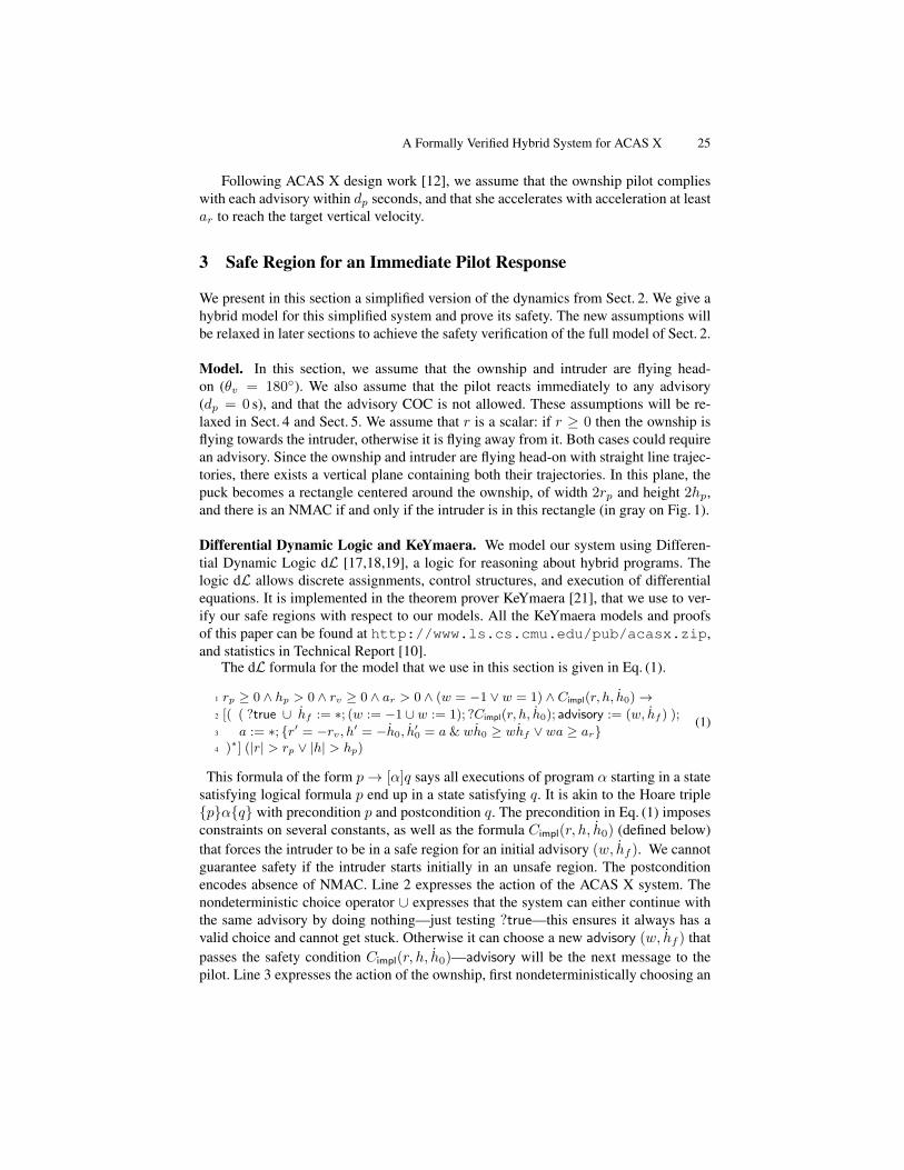
The dL formula for the model that we use in this section is given in Eq. (1).
1 rp ≥ 0 ∧ hp > 0 ∧ rv ≥ 0 ∧ ar > 0 ∧ (w = −1 ∨ w = 1) ∧ Cimpl(r, h, h0)→2 [( ( ?true ∪ hf := ∗; (w := −1 ∪ w := 1); ?Cimpl(r, h, h0); advisory := (w, hf ) );
3 a := ∗; {r′ = −rv, h′ = −h0, h′0 = a & wh0 ≥ whf ∨ wa ≥ ar}
4 )∗] (|r| > rp ∨ |h| > hp)
(1)
This formula of the form p→ [α]q says all executions of program α starting in a statesatisfying logical formula p end up in a state satisfying q. It is akin to the Hoare triple{p}α{q} with precondition p and postcondition q. The precondition in Eq. (1) imposesconstraints on several constants, as well as the formula Cimpl(r, h, h0) (defined below)that forces the intruder to be in a safe region for an initial advisory (w, hf ). We cannotguarantee safety if the intruder starts initially in an unsafe region. The postconditionencodes absence of NMAC. Line 2 expresses the action of the ACAS X system. Thenondeterministic choice operator ∪ expresses that the system can either continue withthe same advisory by doing nothing—just testing ?true—this ensures it always has avalid choice and cannot get stuck. Otherwise it can choose a new advisory (w, hf ) thatpasses the safety condition Cimpl(r, h, h0)—advisory will be the next message to thepilot. Line 3 expresses the action of the ownship, first nondeterministically choosing an

26 Jeannin, Ghorbal, Kouskoulas, Gardner, Schmidt, Zawadzki and Platzer
arbitrary acceleration (a := ∗) then following the continuous dynamics. The evolutionof the variables r, h and h0 is expressed by a differential equation, and requires (usingthe operator &) that the ownship evolves towards its target vertical velocity hf at ac-celeration ar (condition wa ≥ ar), unless it has already reached vertical velocity hf(condition wh0 ≥ whf ). Finally, the star ∗ on line 4 indicates that the program can berepeated any number of times, allowing the system to go through several advisories.
Implicit Formulation of the Safe Region. As explained in Sect. 2, we use a framefixed to the intruder and with its origin at the initial position of the ownship (see Fig. 1).
First case: if w = +1 and hf ≥ h0. Fig. 1 shows, in red, a possible trajectory ofan ownship following exactly the requirements of ACAS X. This nominal trajectoryof the ownship is denoted by N . The pilot reacts immediately, and the ownship startsaccelerating vertically with acceleration ar until reaching the target vertical velocityhf—describing a parabola—then climbs at vertical velocity hf along a straight line.Horizontally, the relative velocity rv remains constant. Integrating the differential equa-tions in Eq. (1) line 3, the ownship position (rt, ht) at time t along N is given by:
(rt, ht) =
(rvt ,
ar
2 t2 + h0t
)if 0 ≤ t < hf−h0
ar(a)(
rvt , hf t− (hf−h0)2
2ar
)if hf−h0
ar≤ t (b)
(2)
Recall that in the ACAS X specification, the ownship moves vertically with accel-eration of at least ar, then continues with vertical velocity of at least hf . Thereforeall possible future positions of the ownship are above the red nominal trajectory. Anintruder is safe if its position is always either to the side of or under any puck centeredon a point in N , that is:
∀t.∀rt.∀ht.((rt, ht) ∈ N → |r − rt| > rp ∨ h− ht < −hp
)(3)
We call this formulation the implicit formulation of the safe region. It does not giveexplicit equations for the safe region border, but expresses them instead implicitly withrespect to the nominal trajectory.
Generalization. The reasoning above is generalized to the case where hf < h0, andsymmetrically to the case w = −1. The most general implicit formulation of the saferegion is Cimpl in Fig. 3, and verified to be safe in KeYmaera:
Theorem 1 (Correctness of implicit safe regions). The dL formula given in Eq. (1) isvalid. That is as long as the advisories obey formula Cimpl there will be no NMAC.
Explicit Formulation of the Safe Region. The implicit formulation of the safe regiongives an intuitive understanding of where it is safe for the intruder to be. However,because it still contains quantifiers, its use comes at the extra cost of eliminating thequantifiers. An efficient comparison with the ACAS X table, as described in Sect. 6,can only be achieved with a quantifier-free, explicit formulation, that we present in thissection. We show that both formulations are equivalent. As for the implicit formulation,we derive the equations for one representative case before generalizing them.

A Formally Verified Hybrid System for ACAS X 27
Implicit formulation
A(t, ht, h0) ≡
(0 ≤ t < max(0, w(hf − h0))
ar∧ ht =
war2t2 + h0t
)
∨
(t ≥ max(0, w(hf − h0))
ar∧ ht = hf t−
wmax(0, w(hf − h0))2
2ar
)Cimpl(r, h, h0) ≡ ∀t.∀rt.∀ht.
(rt = rvt ∧A(t, ht, h0)
→ (|r − rt| > rp ∨ w(h− ht) < −hp)
)Explicit formulation
case1(r, h0) ≡ −rp ≤ r < −rp −rv min(0, wh0)
ar
bound1(r, h, h0) ≡ wr2vh <ar2(r + rp)
2 + wrvh0(r + rp)− r2vhp
case2(r, h0) ≡ −rp −rv min(0, wh0)
ar≤ r ≤ rp −
rv min(0, wh0)
ar
bound2(r, h, h0) ≡ wh < −min(0, wh0)
2
2ar− hp
case3(r, h0) ≡ rp −rv min(0, wh0)
ar< r ≤ rp +
rv max(0, w(hf − h0))
ar
bound3(r, h, h0) ≡ wr2vh <ar2(r − rp)2 + wrvh0(r − rp)− r2vhp
case4(r, h0) ≡ rp +rv max(0, w(hf − h0))
ar< r
bound4(r, h, h0) ≡ (rv = 0) ∨(wrvh < whf (r − rp)−
rv max(0, w(hf − h0))2
2ar− rvhp
)case5(r, h0) ≡ −rp ≤ r < −rp +
rv max(0, w(hf − h0))
ar
bound5(r, h, h0) ≡ wr2vh <ar2(r + rp)
2 + wrvh0(r + rp)− r2vhp
case6(r, h0) ≡ −rp +rv max(0, w(hf − h0))
ar≤ r
bound6(r, h, h0) ≡ (rv = 0 ∧ r > rp)
∨(wrvh < whf (r + rp)−
rv max(0, w(hf − h0))2
2ar− rvhp
)Cexpl(r, h, h0) ≡
(whf ≥ 0→
4∧i=1
(casei(r, h0)→ boundi(r, h, h0))
)
∧
(whf < 0→
6∧i=5
(casei(r, h0)→ boundi(r, h, h0))
)
Fig. 3. Implicit and explicit formulations of the safe region for an immediate response

28 Jeannin, Ghorbal, Kouskoulas, Gardner, Schmidt, Zawadzki and Platzer
First case: if w = +1, rv > 0, h0 < 0 and hf ≥ 0. We are in the case shown inFig. 1 and described in detail above. The nominal trajectory N is given by Eq. (2)(a)and Eq. (2)(b). The boundary of the (green) safe region in Fig. 1 is drawn by either thebottom left hand corner, the bottom side or the bottom right hand corner of the puck.This boundary can be characterized by a set of equations:
0. positions left of the puck’s initial position (r < −rp) are in the safe region;1. then the boundary follows the bottom left hand corner of the puck as it is going
down the parabola of Eq. (2)(a); therefore for −rp ≤ r < −rp − rvh0
ar, the position
(r, h) is safe if and only if h < ar
2r2v(r + rp)
2 + h0
rv(r + rp)− hp;
2. following this, the boundary is along the bottom side of the puck as it is at thebottom of the parabola of Eq. (2)(a); therefore for −rp − rvh0
a ≤ r ≤ rp − rvh0
ar,
the position (r, h) is in the safe region if and only if h < − h20
2ar− hp;
3. then the boundary follows the bottom right hand corner of the puck as it is goingup the parabola of Eq. (2)(a); therefore for rp − rvh0
ar< r ≤ rp +
rv(hf−h0)ar
, the
position (r, h) is safe if and only if h < ar
2r2v(r − rp)2 + h0
rv(r − rp)− hp;
4. finally the boundary follows the bottom right hand corner of the puck as it is goingup the straight line of Eq. (2)(b); therefore for rp +
rv(hf−h0)ar
< r, the position
(r, h) is in the safe region if and only if h < hf
rv(r − rp)− (hf−h0)
2
2ar− hp.
Generalization. The general case is given in the formula Cexpl of Fig. 3. The cases 1-4 and their associated bounds are for the case whf ≥ 0, whereas cases 5 and 6 andassociated bounds are for whf < 0. We again use KeYmaera to formally prove that thisexplicit safe region formulation is equivalent to its implicit counterpart.
Lemma 1 (Correctness of explicit safe regions). If w = ±1, rp ≥ 0, hp > 0, rv ≥ 0
and ar > 0, then the conditions Cimpl(r, h, h0) and Cexpl(r, h, h0) are equivalent.
4 Safe Region for a Delayed Pilot Response
We generalize the model of Sect. 3 to account for a non-deterministic, non-zero pilotdelay, and for periods of time where the system does not issue an advisory (i.e., COC).
Model. In this section, we still assume that the ownship and intruder are flying head-on (θv = 180◦). We use the same conventions as in Sect. 3 for r and rv . The modelincludes an initial period where there is no compliance with any advisory—the ownshipaccelerates non-deterministically (within limits) in the vertical direction. As before, wederive the safe regions by considering all possible positions of the ownship’s puck in allpossible trajectories that might evolve in the encounter. To represent pilot delay for anadvisory, the model assumes an immediate advisory, and period of non-compliance dp,representing the time it takes the pilot to respond. To represent COC, the model looks

A Formally Verified Hybrid System for ACAS X 29
Fig. 4. Trajectory of the ownship (red) and safe region for the intruder (green), delayed responsefor a safe advisory it can issue d` in the future if necessary, (d` being the system delay,and shortest COC) so the period of non-compliance is dp + d`.
1 rp ≥ 0 ∧ hp > 0 ∧ rv ≥ 0 ∧ ar > 0 ∧ ad ≥ ∧dp ≥ 0 ∧ d` ≥ 0
2 ∧(w = −1 ∨ w = 1) ∧Dimpl(r, h, h0, d)→3 [((?true ∪ hf := ∗; (w := −1 ∪ w := 1);
4 (d := dp; ?Dimpl(r, h, h0, d); advisory := (w, hf ) ∪5 d := dp + d`; ?Dimpl(r, h, h0, d); advisory := COC)
);
6 a := ∗; ?(wa ≥ −ad); t` := 0;
7 {r′ = −rv, h′ = −h0, h′0 = a,d′ = −1, t′` = 1 &
8 (t` ≤ d`) ∧ (d ≤ 0→ wh0 ≥ whf ∨ wa ≥ ar)}9 )∗] (|r| > rp ∨ |h| > hp)
(4)
We modify the model of Eq. (1) to capture these new ideas, and obtain the modelof Eq. (4), highlighting the differences in bold. The structure, precondition (lines 1 and2) and postcondition (line 9) are similar. The clock d, if positive, represents the amountof time until the ownship pilot must respond to the current advisory to remain safe.Lines 3 to 5 represent the actions of the ACAS X system. As before, the system cancontinue with the same advisory (?true). Otherwise it can select a safe advisory (w, hf )to be applied after at most delay dp; or it can safely remain silent, displaying COC, if itknows an advisory (w, hf ) that is safe if applied after delay dp + d`. In line 6, the pilotnon-deterministically chooses an acceleration (a := ∗), within some limit (wa ≥ −ad).The set of differential equations in line 7 describes the system’s dynamics, and theconditions in line 8 use the clock t` to ensure that continuous time does not evolvelonger than system delay d` without a system response (t` ≤ d`). Those conditionsalso ensure that when d ≤ 0 the pilot starts complying with the advisory. The modelis structured so that the pilot can safely delay responding to an advisory for up to dp,and to an advisory associated with COC for up to dp + d`—considering upper boundson the reaction delay is necessary to get a formal proof of safety. Because of the loopin our model (line 9), the safety guarantees of this theorem apply to encounters whoseadvisories change as the encounter evolves, encounters with periods of no advisory, andencounters where the pilot exhibits some non-deterministic behavior.
In the rest of the section we use the same approach as in Sect. 3: we first derivean implicit formulation, then an equivalent explicit formulation of the safe region, andprove that the safe region guarantees that the intruder cannot cause an NMAC.

30 Jeannin, Ghorbal, Kouskoulas, Gardner, Schmidt, Zawadzki and Platzer
Implicit formulation
B(t, ht, h0, d) ≡ 0 ≤ t < max(0, d) ∧ ht = −wad2t2 + h0t
const ≡ hd = −wad2
max(0, d)2 + h0 max(0, d) ∧ hd − h0 = −wad max(0, d)
Dimpl(r, h, h0, d) ≡ ∀t.∀rt.∀ht.∀hd.∀hd.(rt = rvt ∧ (B(t, ht, h0, d) ∨ const ∧A(t−max(0, d), ht − hd, hd))
→ (|r − rt| > rp ∨ w(h− ht) < −hp))
Explicit formulationrd = rv max(0, d) hd = h0 − wad max(0, d)
hd = −wad2
max(0, d)2 + h0 max(0, d)
case7(r) ≡ −rp ≤ r ≤ rp bound7(r, h) ≡ wh < −hp
case8(r) ≡ rp < r ≤ rd + rp case9(r) ≡ −rp ≤ r < rd − rp
bound8(r, h) ≡ wr2vh < −ad2(r − rp)2 + wrvh0(r − rp)− r2vhp
bound9(r, h) ≡ wr2vh < −ad2(r + rp)
2 + wrvh0(r + rp)− r2vhp
Dexpl(r, h, h0, d) ≡
(9∧
i=7
(casei(r)→ boundi(r, h))
)∧ Cexpl(r − rd, h− hd, hd)
Fig. 5. Implicit and explicit formulations of the safe region for a delayed response
Formulations of the Safe Region. As in Sect. 3, let us place ourselves in the referentialcentered on the current position of the ownship and where the intruder is fixed, and let usfirst assume that the ownship receives an advisory (w, hf ) such that w = +1, and thatd ≥ 0. Let us focus on the period of time before the pilot reacts, which we henceforthcall delay. During the delay, the ownship can take any vertical acceleration less than adin absolute value, therefore its nominal trajectory Nd is to accelerate the opposite wayof the advisory, at acceleration −ad. Horizontally, its speed is constant at rv . It thusdescribes a delay parabola, in red on Fig. 4, and its position (rt, ht) along the nominaltrajectory for 0 ≤ t < d is given by (rt, ht) =
(rvt,−ad
2 t2 + h0t
).
After the delay, i.e., after time d, the nominal trajectoryNd is the same as a nominaltrajectory N from Sect. 3, translated by time d and by its position at time d given byrd = rt(d) and hd = ht(d), and starting with vertical velocity hd = h0 − add. As inSect. 3, we can now express the implicit formulation of the safe region:
∀t.∀rt.∀ht.((rt, ht) ∈ Nd → |r − rt| > rp ∨ h− ht < −hp
)Symmetrically, the reasoning of this section extends to the case where w = −1. More-over, we can handle cases where d < 0, i.e., after the pilot has reacted, by replacing dby max(0, d). The generalized implicit formulation of the safe region is given as Dimpl
in Fig. 5. Note that it involves the expression A(t−max(0, d), ht−hd, hd) from Fig. 3capturing the implicit safe region of Sect. 3 translated by time max(0, d), vertical heighthd, and starting at vertical speed hd. It is proved correct in KeYmaera.

A Formally Verified Hybrid System for ACAS X 31
Theorem 2 (Correctness of delayed safe regions). The dL formula given in Eq. (4) isvalid. That is as long as the advisories obey formula Dimpl there will be no NMAC.
Similarly as in Sect. 4, we determine an explicit formulation of the safe region, calledDexpl in Fig. 5 based on Fig. 3, and prove it correct in KeYmaera.
Lemma 2 (Correctness of delayed explicit safe regions). If w = −1 or w = +1,rp ≥ 0, hp > 0, rv ≥ 0, ar > 0, ad ≥ 0, dp ≥ 0 and d` ≥ 0 then the two conditionsDimpl(r, h, h0, d) and Dexpl(r, h, h0, d) are equivalent.
5 Reduction from 3D Dynamics to 2D Dynamics
In this section, we show that, with respect to our assumptions, any 3-dimensional en-counter (Sect. 2) can be reduced to a 2-dimensional encounter (Sect. 3) without loss ofgenerality. This is done using a change of reference frame and a dimension reduction.
For the sake of clarity, let us use a reference frame (O,~i,~j,~k) fixed to the ownship(O). In this reference frame, the position of an intruder I is represented by the tuple(x, y, h), and the differential equation system that governs its motion is given by x =rx, y = ry , h = a, where rx, ry and a remain constant as time evolves. Therefore, themotion of the encounter can be decoupled into a 2-dimensional horizontal encounter inthe reference frame (O,~i,~j) (horizontal plane) and a 1-dimensional vertical encounterin the reference frame (O,~k). In what follows, we reduce the horizontal encounter froma 2-dimensional motion to a 1-dimensional motion, thereby simplifying the problemconceptually and computationally by reducing its number of variables.
Fig. 6 depicts a top view of a generic encounter. We denote by ~r the position, and~rv the velocity, of the intruder relative to the ownship, and by rv ≥ 0 the norm of ~rv .
O
I
~r
−~rv
~i
~j
~i′~j′
O′s
n
Fig. 6. Top view of the two reference frames
First suppose rv > 0. The idea isto choose a reference frame (O′,~i′,~j′)
in which one axis ~i′ is aligned with ~rv ,such that no relative motion happens inthe other direction ~j′. Its fixed center O′
is defined as the orthogonal projection ofpoint O on the direction of ~rv . The unitvector~i′ is defined as ~rv
rv, and ~j′ is a unit
such that (O′,~i′,~j′) is positively oriented.Let ~v|O (resp. ~v|O′ ) denote the coordi-
nates of a vector ~v relative to the referenceframe (O,~i,~j) (resp. (O′,~i′,~j′)). Then, the coordinates for ~r and ~rv are: ~r|O = (x, y),~rv|O = (rx, ry), ~r|O′ = (s, n) and ~rv|O′ = (−rv, 0). The scalar product ~r · ~rv and thecross product ~r × ~rv are independent of the horizontal reference frame, therefore:
xrx + yry = −srv xry − yrx = nrv (5)
Given rx and ry , Eqns. (5) imply that the coordinates (x, y) are uniquely determinedby the choice of (s, n), as long as rv 6= 0 (using r2v = r2x + r2y). For any 2-dimensionalconfiguration, the encounter can thus be considered a head-on encounter where s playsthe role of r and where a new puck radius, denoted sp, plays the role of rp.

32 Jeannin, Ghorbal, Kouskoulas, Gardner, Schmidt, Zawadzki and Platzer
Table 2. Summary of the points of the state space at which we examined ACAS X
Range Relative speed Angle Relative Vertical rates Previousr (ft) rv (ft/s) θv (degrees) altitude h (ft) h0, h1 (ft/s) advisory
Min value 1,500 100 180◦ -4,000 -41.67 NoneMax value 200,000 2,200 180◦ 4,000 41.67 NoneNumber of values 80 10 1 33 132 1
Let us now determine the radius sp of the dimension-reduced encounter, and provethat the absence of NMAC in (O,~i,~j)—characterized by r2 > r2p—is equivalent to theabsence of NMAC in (O′,~i′,~j′)—characterized by s2 > s2p. Using (5):
r2vr2 = r2v(x
2 + y2) = (xrx + yry)2 + (xry − yrx)2 = r2v(s
2 + n2) .
Since rv 6= 0, this implies r2 = s2+n2. Therefore, r2 > r2p if and only if s2+n2 > r2por equivalently s2 > r2p − n2. If r2p − n2 < 0, the direction of the vector ~rv does notintersect the puck, the inequality s2 > r2p−n2 is trivially true, and the encounter is safe.If r2p−n2 ≥ 0, we choose the new puck radius sp for the dimension-reduced encounteras sp =
√rp2 − n2 ≥ 0, and the safety condition in (O′,~i′,~j′) becomes s2 ≥ s2p.
When θv = 180◦, one has s = r, n = 0 and sp = rp as in Sect. 3–4.As the encounter evolves in (O,~i,~j) along x = rx, y = ry , its dimension-reduced
version evolves in (O′,~i′,~j′) along the differential equations s = −rv, n = 0, obtainedby differentiating Eqns. (5) and canceling rv . The following proposition, proved inKeYmaera, combines both dynamics and shows that the absence of an NMAC of radiusrp in (O,~i,~j) is equivalent to the absence of an NMAC of radius sp in (O′,~i′,~j′).
Proposition 1 (Horizontal Reduction). The following dL formula is valid(xrx + yry = −srv ∧ xry − yrx = nrv ∧ x2 + y2 = n2 + s2 ∧ r2v = r2x + r2y
)→ [x = rx, y = ry, s = −rv, n = 0]
(x2 + y2 > r2p ↔ s2 > r2p − n2
)(6)
Observe that the horizontal NMAC condition in (O′,~i′,~j′) only depends on the changeof one variable rather than two. The proposition also applies to the special case rv = 0.In this case the origin O′ is no longer defined, and Eqns. (5) are trivially true. Thevariables s and n are constants (s = 0, n = 0), their initial values are only restricted bythe condition n2 + s2 = x2 + y2 in the assumption of the proposition, but they are notunique. When the relative position between the two aircraft does not evolve over time,if the intruder is at a safe distance initially, the encounter is still safe for all time.
6 Initial Examination of the Safety of ACAS X
In this section, we use Theorem 1 to check the safety of advisories given by ACAS X.We focus on Run 12 (July 2014) of the optimized logic tables, a core component ofACAS X. The full policy of the system is built on these lookup tables and incorpo-rates additional components to handle various operational scenarios. We compare theACAS X table to the explicit regions where the pilot reacts immediately (Sect. 3). Fora given initial state of an encounter, we query the first advisory issued by ACAS Xand check its safety as identified in Theorem 1. In a real scenario, ACAS X could later

A Formally Verified Hybrid System for ACAS X 33
Fig. 7. Original ownship path (cyan) and intruder path (red) vs. ownship responding to a do-not-climb (DNC) advisory issued by the ACAS X tables in starting state: r = 4,000 ft, rv = 200 ft/s,θv = 180◦, h = 600 ft, h0 = 1,980 ft/min, h1 = −1,500 ft/min.
strengthen or reverse the first advisory as the encounter evolves. But the safety of thefirst advisory is critical from an operational prospective as later changes are undesirable.
Our initial analysis considers a nominal set of discrete states—summarized in Ta-ble 2—of the ACAS X MDP model where no advisory has yet been issued. All com-pared states are head-on encounters: in a sense, they are the most obviously dangerousconfigurations. For those states, the ACAS X advisories are compared against the saferegions stated in Fig. 3. Overall, 4,461,600 discrete states were examined, among which44,306 states (1.2%) did not meet the conditions of Fig. 3: 11,524 of these were unre-solvable, i.e., the intruder was too close for any advisory to avoid NMAC; while 32,782could have been resolved with a different safe advisory that satisfies Theorem 1.
Our analysis led to the identification of unexpected behavior in the ACAS X lookuptables. In some cases, the ACAS X advisory seems to induce an NMAC (Fig. 7), i.e.,if the initial advisory is not strengthened or reverted later, an NMAC will occur. Inother cases, the advisory does not seem to have any benefit, that is flying at verticalrates disallowed by the advisory would actually avoid NMAC while not all allowedvertical rates are safe. Of course, such unsafe advisories would be disallowed by oursafe regions. Notice that these behaviors are not necessarily all deemed undesirable,as ACAS X tries to minimize alerting the pilot unless it has to do so; for some cases,ACAS X will strengthen the advisory later and hence does not issue a disruptive alertimmediately. Fig. 7 depicts a typical example where the ACAS X advisory induces anNMAC. The ownship is flying from the left and the intruder from the right. As timecounts down, the intruder evolves towards the ownship and an NMAC happens at t = 0.The original path of the ownship does not lead to an NMAC. However, ACAS X gives aDo-Not-Climb advisory. If the pilot, following this advisory, decides to stop climbing,its trajectory will cause an NMAC. (Other examples are in Technical Report [10].)
The development of the safe regions gave an insight into possible improvements forthe ACAS X system. Although we are not analyzing the complete system, nor the subse-quent advisories, we automatically pointed out some subregions of the state space worthlooking at. Some of those problems were independently identified by the ACAS X teamusing simulation-based testing, and will be addressed in subsequent revisions of the sys-tem. When extended to check contiguous regions of the state space, our approach will
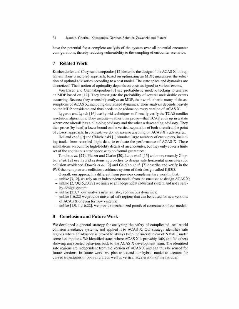
34 Jeannin, Ghorbal, Kouskoulas, Gardner, Schmidt, Zawadzki and Platzer
have the potential for a complete analysis of the system over all potential encounterconfigurations, thereby reducing vulnerability to the sampling of encounter scenarios.
7 Related Work
Kochenderfer and Chryssanthacopoulos [12] describe the design of the ACAS X lookup-tables. Their principled approach, based on optimizing an MDP, guarantees the selec-tion of optimal advisories according to a cost model. The state space and dynamics arediscretized. Their notion of optimality depends on costs assigned to various events.
Von Essen and Giannakopoulou [3] use probabilistic model-checking to analyzean MDP based on [12]. They investigate the probability of several undesirable eventsoccurring. Because they ostensibly analyze an MDP, their work inherits many of the as-sumptions of ACAS X, including discretized dynamics. Their analysis depends heavilyon the MDP considered and thus needs to be redone on every version of ACAS X.
Lygeros and Lynch [16] use hybrid techniques to formally verify the TCAS conflictresolution algorithms. They assume—rather than prove—that TCAS ends up in a statewhere one aircraft has a climbing advisory and the other a descending advisory. Theythen prove (by hand) a lower bound on the vertical separation of both aircraft at the pointof closest approach. In contrast, we do not assume anything on ACAS X’s advisories.
Holland et al. [9] and Chludzinski [1] simulate large numbers of encounters, includ-ing tracks from recorded flight data, to evaluate the performance of ACAS X. Thesesimulations account for high-fidelity details of an encounter, but they only cover a finiteset of the continuous state space with no formal guarantees.
Tomlin et al. [22], Platzer and Clarke [20], Loos et al. [15] and more recently Ghor-bal et al. [8] use hybrid systems approaches to design safe horizontal maneuvers forcollision avoidance. Dowek et al. [2] and Galdino et al. [7] describe and verify in thePVS theorem prover a collision avoidance system of their design called KB3D.
Overall, our approach is different from previous complementary work in that:– unlike [3,12], we rely on an independent model from the one used to design ACAS X;– unlike [2,7,8,15,20,22] we analyze an independent industrial system and not a safe-
by-design system;– unlike [2,3,7] our analysis uses realistic, continuous dynamics;– unlike [16,22] we provide universal safe regions that can be reused for new versions
of ACAS X or even for new systems;– unlike [1,9,11,16,22], we provide mechanized proofs of correctness of our model.
8 Conclusion and Future Work
We developed a general strategy for analyzing the safety of complicated, real-worldcollision avoidance systems, and applied it to ACAS X. Our strategy identifies saferegions where an advisory is proved to always keep the aircraft clear of NMAC, undersome assumptions. We identified states where ACAS X is provably safe, and fed othersshowing unexpected behaviors back to the ACAS X development team. The identifiedsafe regions are independent from the version of ACAS X and can thus be reused forfuture versions. In future work, we plan to extend our hybrid model to account forcurved trajectories of both aircraft as well as vertical acceleration of the intruder.

A Formally Verified Hybrid System for ACAS X 35
Acknowledgments. The authors would like to warmly thank Stefan Mitsch and Jan-David Quesel for their support of the KeYmaera tool. The authors would also like tothank Jeff Brush, Jessica Holland, Robert Klaus, Barbara Kobzik-Juul, Mykel Kochen-derfer, Ted Londner, Sarah Loos, Ed Morehouse, Wes Olson, Michael Owen, JoshuaSilbermann, Neal Suchy, and the ACAS X development team for interesting remarks.
References
1. Chludzinski, B.J.: Evaluation of TCAS II version 7.1 using the FAA fast-time encountergenerator model. Tech. Rep. ATC-346, MIT Lincoln Laboratory (April 2009)
2. Dowek, G., Munoz, C., Carreno, V.: Provably safe coordinated strategy for distributed con-flict resolution. In: AIAA Guidance Navigation, and Control Conference and Exhibit (2005)
3. von Essen, C., Giannakopoulou, D.: Analyzing the next generation airborne collision avoid-ance system. In: TACAS, LNCS, vol. 8413, pp. 620–635. Springer (2014)
4. Federal Aviation Administration: Introduction to TCAS II (February 2011), version 7.15. Federal Aviation Administration TCAS Program Office: Algorithm design description for
the surveillance and tracking module of ACAS X (July 2014), run126. Federal Aviation Administration TCAS Program Office: Algorithm design description for
the threat resolution module of ACAS X (May 2014), version 3 Rev. 17. Galdino, A., Munoz, C., Ayala, M.: Formal verification of an optimal air traffic conflict
resolution and recovery algorithm. In: WoLLIC. LNCS, vol. 4576. Springer (2007)8. Ghorbal, K., Jeannin, J.B., Zawadzki, E., Platzer, A., Gordon, G.J., Capell, P.: Hybrid theo-
rem proving of aerospace systems: Applications and challenges. Journal of Aerospace Infor-mation Systems (2014)
9. Holland, J.E., Kochenderfer, M.J., Olson, W.A.: Optimizing the next generation collisionavoidance system for safe, suitable, and acceptable operational performance. Air Traffic Con-trol Quarterly (2014)
10. Jeannin, J.B., Ghorbal, K., Kouskoulas, Y., Gardner, R., Schmidt, A., Zawadzki, E., Platzer,A.: A formally verified hybrid system for the next-generation airborne collision avoid-ance system. Tech. Rep. CMU-CS-14-138, School of Computer Science, Carnegie MellonUniversity, Pittsburgh, PA (2014), http://reports-archive.adm.cs.cmu.edu/anon/2014/CMU-CS-14-138.pdf, KeYmaera files available at http://www.ls.cs.cmu.edu/pub/acasx.zip
11. Kochenderfer, M.J., Espindle, L.P., Kuchar, J.K., Griffith, J.D.: Correlated encounter modelfor cooperative aircraft in the national airspace system version 1.0. Tech. Rep. ATC-344,MIT Lincoln Laboratory (October 2008)
12. Kochenderfer, M.J., Chryssanthacopoulos, J.P.: Robust airborne collision avoidance throughdynamic programming. Tech. Rep. ATC-371, MIT Lincoln Laboratory (January 2010)
13. Kochenderfer, M.J., Holland, J.E., Chryssanthacopoulos, J.P.: Next generation airborne col-lision avoidance system. Lincoln Laboratory Journal 19(1), 17–33 (2012)
14. Kochenderfer, M.J., Monath, N.: Compression of optimal value functions for Markov deci-sion processes. In: Data Compression Conference. Snowbird, Utah (2013)
15. Loos, S.M., Renshaw, D.W., Platzer, A.: Formal verification of distributed aircraft con-trollers. In: HSCC. pp. 125–130. ACM (2013)
16. Lygeros, J., Lynch, N.: On the formal verification of the TCAS conflict resolution algorithms.In: IEEE Decision and Control. vol. 2, pp. 1829–1834. IEEE (1997)
17. Platzer, A.: Differential dynamic logic for hybrid systems. J. Autom. Reas. 41(2), 143–189(2008)

36 Jeannin, Ghorbal, Kouskoulas, Gardner, Schmidt, Zawadzki and Platzer
18. Platzer, A.: Logical Analysis of Hybrid Systems: Proving Theorems for Complex Dynamics.Springer (2010)
19. Platzer, A.: Logics of dynamical systems. In: LICS. pp. 13–24. IEEE (2012)20. Platzer, A., Clarke, E.M.: Formal verification of curved flight collision avoidance maneuvers:
A case study. In: FM. LNCS, vol. 5850, pp. 547–562. Springer (2009)21. Platzer, A., Quesel, J.D.: KeYmaera: A hybrid theorem prover for hybrid systems. In: IJCAR.
LNCS, vol. 5195, pp. 171–178. Springer (2008)22. Tomlin, C., Pappas, G.J., Sastry, S.: Conflict resolution for air traffic management: A study in
multiagent hybrid systems. IEEE Transactions on Automatic Control 43(4), 509–521 (1998)