Embed Size (px)
Citation preview

Journal of Computer and Communications, 2017, 5, 62-73 http://www.scirp.org/journal/jcc
ISSN Online: 2327-5227 ISSN Print: 2327-5219
DOI: 10.4236/jcc.2017.55006 March 30, 2017
A Flat Mobile Core Network for Evolved Packet Core Based SAE Mobile Networks
Mohammad Al Shinwan, Trong-Dinh Huy, Kim Chul-Soo
Faculty of Computer Engineering, Inje University, Gimhae, Republic of Korea
Abstract In the current mobile IPv6 (MIPv6) systems for the System architecture eval-uation (SAE) networks, such as 4th generation (4G) mobile network, the data delivery is performed basing on a centralized mobility network anchor be-tween Evolved Node B (eNB) and Serving Gateways (S-GW), and also be-tween S-GW and Packet Data Network Gateway (P-GW). However, the exist-ing network has many obstacles, including suboptimal data routing, injection of unwanted data traffic into mobile core network and the requirement of capital expenditure. To handle these challenges, here we describe a flat mobile core network scheme donated by F-EPC, based SAE mobile network. In the proposed scheme, the P-GW and S-GW gateways are features as one node named Cellular Gateway (C-GW). Further, we proposed to distribute and in-crease the number of C-GW in mobile core network, the Mobility Manage-ment Entity (MME) functioned as centralizing mobility anchor and allocating the IP address for the User Entity (UE). In this paper, the explained results of a simulation analysis showed that the proposed scheme provides a superior performance compared with the current 4G architecture in terms of total transmission delay, handover delay and initial attach procedure.
Keywords SAE, EPC, F-EPC, Flat Network, DMM, Mobility
1. Introduction
One of the most challenging issues facing the mobile networks operators is how to design the future mobile network (i.e., 5th generation Network (5G)) [1]. The need for the mobile system is based on the huge traffic demand and the increase in the use of smart phones and other mobile devices. This trend appears likely to continue, and the volume of mobile data traffic will increase eight-fold be-tween 2015 and 2020 [2]. This growth in mobile data traffic places increasing
How to cite this paper: Shinwan, M.A., Huy, T.-D. and Chul-Soo, K. (2017) A Flat Mobile Core Network for Evolved Packet Core Based SAE Mobile Networks. Journal of Computer and Communications, 5, 62-73. https://doi.org/10.4236/jcc.2017.55006 Received: February 12, 2017 Accepted: March 27, 2017 Published: March 30, 2017 Copyright © 2017 by authors and Scientific Research Publishing Inc. This work is licensed under the Creative Commons Attribution International License (CC BY 4.0). http://creativecommons.org/licenses/by/4.0/
Open Access

M. A. Shinwan et al.
63
demands on wireless communication systems, and represents a major challenge for cellular providers in terms of upgrading their core networks to accommodate future network requirements and keeping up with increasing customer demand [3] [4].
The need for a new network architecture is essential to support growth in de-mand for broadband services of various kinds delivered over the networks, and to support Internet of Things (IoT) services and applications [5].
The System Architecture Evolution (SAE) [6] is defined as the non-radio core architecture of Long Term Evolution (LTE) networks developed by 3 GPP and aims to support low latency, high throughput and the mobility between mul-ti-heterogeneous networks. It is an evolution of the General Packet Radio Service (GPRS) network, the Evolved Packet Core (EPC) is the most important compo-nent. EPC networks are formed of several functional entities: 1) P-GWs, which provide mobile users an access to a PDN by allocating the IP addresses, and also provide IP routing and forwarding S-GWs; 2) Mobility Management Entities (MMEs) that provide several functions, including mobility management and handover management; 3) Home Subscriber Servers (HSSs) provide user profiles and authentication data and Policy and Charging Rules Function (PCRF) serv-ers; 4) S-GWs act as local mobility anchors for inter-eNB handover; 5) PCRF controls the charging rules and quality of service.
At an EPC network, data paths are established between eNBs and P-GWs via S-GWs, and uses GPRS Tunneling Protocol (GTP) for tunneling. P-GWs and S-GWs perform as centralized mobility anchors for data packets; consequently, all data traffic is forward through a centralized anchor S-GW and P-GW.
As shown in Figure 1, the EPC architecture composed from several interfaces to forward the data, including X2, S1-MME, S11, S5 and S1-U. The X2 interface protocol supports UE mobility by creating a GTP tunnel between eNBs.
Figure 1. 4 G mobile network model.

M. A. Shinwan et al.
64
S1-MME provides the initial UE context to MMEs, and is also responsible for establishing and controlling the GTP tunnel between MMEs and S-GWs. S5 provides GTP tunnel functionality between S-GWs and P-GWs. The S1-U inter-face provides GTP tunnel function between eNBs and S-GWs.
On the other hand, the 4G network has a number of limitations. First, there are load balance and latency issues; the growth in data traffic requires a reduc-tion in the transmission and connection delays. In addition; simplifying the mo-bile core and reducing the number of identifications can make mobile core net-works simpler and more efficient, and hence more cost-effective. The second problem is suboptimal routing; the uplink and downlink data packets are routed via mobility anchors, which often result in the suboptimal paths. For example, where a data packet is sent from one mobile device to another in the same net-work domain or local server, instead of taking the shortest path, the packet is routed via a P-GW and an S-GW. The last limitation is the required capital ex-penditure: The EPC network is simply not cost-effective, due to the huge num-ber of routers that are required to support the core network.
To overcome these issues, a variety of approaches have been proposed. A mo-bility data offloading approach uses femtocell, where the data traffic is forwarded to the mobile device without using the core network [7]. Another approach to distribute the mobility in 4G network is the Distributed Mobility Management (DMM) [8], proposed by Internet Engineering Task Force (IETF), which pro-vides mobility with localized mobility anchors that are distributed within the network, in combination with centralized anchors where the system is arranged in a hierarchical model [9].
Another approach to distribute mobility in 4G networks is the Ultra Flat Ar-chitecture (UFA). The key element of UFA is to decrease the number of the network nodes to one (i.e., a single base station), based on the distribution of user and control plane roles in the node. UFA provides improved performance and seamless handover [10].
However, the previous proposed architectures have some problems associated with mobility anchoring and suboptimal data routing. Moreover, from the pers-pective of capital expenditure, most of the proposed architectures are not cost-effective.
In this paper, we propose a flat mobile core network scheme in EPC for SAE mobile based network, termed F-EPC. In this proposed scheme, the P-GW and S-GW gateways work as one node named Cellular Gateway (C-GW). We also propose to distribute and increase the number of C-GWs in mobile core net-work and which will be transferred between both gateways. The Mobile Man-agement Entity (MME) will manage the control and the data plane, assign the IP addresses and control the C-GWs.
2. Mobility Management in 4G Networks 2.1. Initial Attach Procedure
Figure 2 shows the initial attach registration procedure for a 4G network. When

M. A. Shinwan et al.
65
Figure 2. Initial attach procedure in a 4G network.
the UE establishes radio link synchronization with an eNB, the UE creates a connection for data delivery via an Attach Request message sent to the eNB, the eNB then forwards the attach request to an MME, which in its turn sends an Update Location Request to an HSS. The HSS responds via an Update Location Answer, and then the MME performs the required security related-operations with UE. The MME sends a Create Session Request to an S-GW to build a transmission path. The S-GW now sends a Create Session Request to a P-GW, which responds by sending a Create Session Request Response message. The S-GW then sends a Create Session Response to the MME, and the MME sends an Attach Accept message to the UE. The MME now performs an Initial Context Setup with the eNB, and the eNB sends an Initial Context Setup Response mes-sage to the MME. The UE then sends an Attach Complete message to the MME, which sends a Modify Bearer Request to the S-GW, which responds by sending a Modify Bearer Response message to the MME.
2.2. Initial Handover Procedure
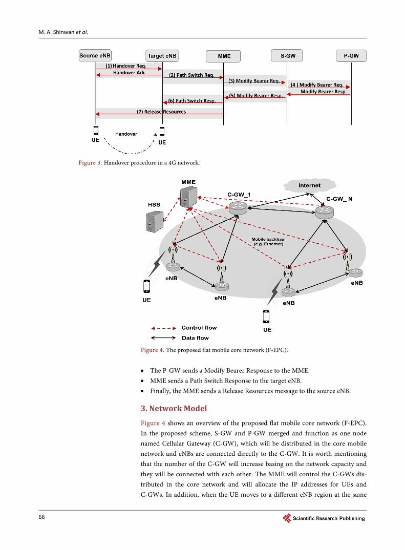
Figure 3 shows handover procedure in 4G network, which takes the following steps: • When the UE moves to another eNB region, the source eNB sends a Han-
dover Request to the target eNB, which responds with a Handover Acknowl-edgment.
• The target eNB then sends a Path Switch Request to the MME. • MME sends a Modify Bearer Request to the S-GW. • The S-GW exchanges the modify bearer messages with the P-GW via a Mod-
ify Bearer Request and a Modify Bearer Response.
M. A. Shinwan et al.
66
Figure 3. Handover procedure in a 4G network.
Figure 4. The proposed flat mobile core network (F-EPC).
• The P-GW sends a Modify Bearer Response to the MME. • MME sends a Path Switch Response to the target eNB. • Finally, the MME sends a Release Resources message to the source eNB.
3. Network Model
Figure 4 shows an overview of the proposed flat mobile core network (F-EPC). In the proposed scheme, S-GW and P-GW merged and function as one node named Cellular Gateway (C-GW), which will be distributed in the core mobile network and eNBs are connected directly to the C-GW. It is worth mentioning that the number of the C-GW will increase basing on the network capacity and they will be connected with each other. The MME will control the C-GWs dis-tributed in the core network and will allocate the IP addresses for UEs and C-GWs. In addition, when the UE moves to a different eNB region at the same

M. A. Shinwan et al.
67
network or different network, MME will select another C-GW. MME with HSS is used for UE registration and to obtain subscription information on the UE. MME with HSS is also used to register the MME ID and indicate in which MME the UE is located.
3.1. F-EPC Initial Attach Procedure
Figure 5 shows the initial attach registration procedure used with F-EPC scheme, which explained on the following steps: • When the UE establishes radio link synchronization with the eNB, the UE
sends an Attach Request message to the eNB. • The eNB sends the Attach Request to the MME, which sends an Authentica-
tion Information to the HSS, as well as a Network Attach Storage (NAS) re-quest. Once these authentications and NAS security procedures are accom-plished, the MME sends an Update Location Request to the HSS, which in-dicates in which MME the UE is located. The HSS responds by sending an Update Location Answer.
• In step 3, the MME sends a request to the C-GW to allocate a gateway ad-dress for the UE via the exchanging of Switch Control Request and Switch Control Response messages.
• An IP address is then allocated to the UE by the eNB via exchange of a Switch Control Request and a Switch Control Response.
Figure 5. The initial attach procedure.

M. A. Shinwan et al.
68
• Following allocation of the IP address and establishment of a gateway, the MME responds to the eNB with an Attach Accept message, which contains the IP addresses of the UE IP.
• The eNB then sends an Attach Accept message to the UE. • The UE sends an Attach Complete message to the eNB.
3.2. F-EPCH and Over Procedure
Figure 6 shows the F-EBCH handover procedure, during which the following steps are taken: • UE moves from the source eNB to the target eNB. • The source eNB sends a Handover Request to the target eNB, which responds
with a Handover Acknowledgment. • The target eNB sends a Path Switch Request to the MME. • The MME then sends a Path Control Request to the C-GW to inform the
C-GW that the UE has moved to a new eNB. • The C-GW sends a Path Control Response to the MME. • The MME sends a Path Switch Response to the target eNB. • Finally, the target eNB sends a Release Resources message to the source eNB.
4. Simulation Result
We evaluate the performance of the F-EPC model by using NS-3 simulation [11]. For the 4G network many simulations have been proposed i.e. LENA project [12] where the simulation composed of two models, LTE model and EPC model. The LTE model operates the lower and upper protocol stack, whereas the EPC model features mobile core network. However, LENA simulation has nu-merous drawbacks. First, S-GW and P-GW are combined within a single node. Thus, gateway relocation mobility and S5/S8 interfaces are not supported. Se-condly, current 4G network uses GTP protocol version 2 (GTPv2), nerveless LENA simulation build up by the old version GTPv1. Finally, the socket trans-mission used for data plane (GTP-U) disregarding the control plane (GTP-C).
Figure 6. Handover procedure.

M. A. Shinwan et al.
69
Consequently, these issues give inaccurate results to compare with the proposed work.
To overcome these challenges, we rebuild the current LENA simulation as follow: first decouple the S-GW and P-GW, by creating a separated S-GW node and modify the P-GW. Secondly, implement the latest version of GTP protocol GTP (GTPv2) with full features instead of the old version GTPv1. Third, we create a S5/S8 interface connection between S-GW and P-GW as well as imple-menting fully signaling messages between the two nodes (S-GW and P-GW). Finally, create a socket transmission to support both control plane (GTP-C) and data plane (GTP-U).
Moreover, we used the implementation, previously described, to run the F-EPC scheme simulation. The NS-3 version 3.22 in Linux environment has been used. The programming of proposed approach consists of building UE, eNB, MME and C-GW. Control plane and data plane implemented into corres-ponding interface. A remote host node is created to act as Internet server, which is able to send packets to other nodes. The rest of simulation parameters are configured as shown in Table 1.
This simulation is built to measure the performance between 4G network and the proposed F-EPC model as follow: total transmission delay for the data pack-ets delivered from the UE to remote host, Handover delay and initial attach procedure delay. To measure the performance of the F-EPC, we will compare four different scenarios as follow:
First scenario: the first scenario presents the current 4G network as described previously in Figure 1.
Second scenario: Figure 7 depicts the second scenario, where we combine S-GW and P-GW in C-GW node. Also, we use two different C-GWs and each C-GW is connected with ten eNBs, and each eNB is connected with one UE.
Third scenario: Figure 8 explains the third scenario, where we create five C-GWs and each C-GW is connected with four eNBs and each eNB is connected with one UE.
Fourth scenario: Figure 9 shows this scenario, it illustrates F-EPC model, where we create 10 C-GWs, each C-GW is connected with two different eNBs and each eNB is connected with one UE.
Table 1. Simulation Parameters.
Parameter Setting
Number of UE One node
Speed of UE Varies from 5 to 120 km/h
eNBTx power 46 dBm
Distance between eNB 100 meters
EPS Bearer NGBR-VIDEO-TCP
QCI 9
Bandwidth 5 MHz
Data rate 10 Gbps

M. A. Shinwan et al.
70
Figure 7. Second scenario.
Figure 8. Third scenario.
Figure 9. F-EPC Model.

M. A. Shinwan et al.
71
Figure 10 shows the transmission delay between the UE and the remote host. The transmission delay for the first scenario is significantly increasing with the data path because the data packets are delivered by centralized anchor P-GW and S-GW. The second scenario increased too because the data packets are deli-vered to the remote host by two C-GWs. The third scenario has a better result comparing with the previous scenarios because the data packets are delivered via one C-GW for each four eNBs. Finally, the fourth scenario shows a superior performance because the data packets are delivered by one C-GWs for each two eNBs.
Figure 11 and Figure 12 shows the handover delay and initial attach delay for each signaling message. The simulation results for both procedures show that there is no big difference between the proposed scheme and 4G network. How-
Figure 10. Total transmission delay.
Figure 11. Handover delay.

M. A. Shinwan et al.
72
Figure 12. Initial attach delay.
ever, the number of signaling messages for the proposed work in handover delay and initial attach are less than those at the 4G network.
5. Conclusion
The current 4G mobile packet core (i.e., EPC) is complex and expensive. We have described a flat mobile network basing on the merge of the S-GW and P-GW in one node and the increase of the C-GW amount. The proposed scheme (F-EPC) achieves better performance than 4G network particularly in total transmission delay for data delivery form the user equipment to the remote host. We compare our work with the existing 4G network architecture using NS-3 simulation. The results show that the proposed scheme results in better perfor-mance than 4G network in term of total transmission delay, the handover delay and initial attach procedure.
References [1] Shinwan, M.A. and Chul-Soo, K. (2017) Enhanced Mobile Packet Core Network
Scheme for Next-Generation Mobile Communication Systems. International Jour-nal of Electronics Communication and Computer Engineering (IJECCE), 8, 56-61.
[2] Cisco (2016) Visual Networking Index: Global Mobile Data Traffic Forecast Update, 2015 - 2020. White Paper.
[3] Ayanoglu, E. (2016) Fifth Generation (5G) Cellular Wireless: Vision, Goals, and Challenges. IEEE 35th International Performance Computing and Communications Conference (IPCCC), Las Vegas, 9-11 December 2016, 1-3. https://doi.org/10.1109/pccc.2016.7820594
[4] FP7 METIS Project (2013) Mobile and Wireless Communications Enablers for the 2020 Information Society. http://www.metis2020.com
[5] Ericsson, Huawei and Qualcomm (2015) The Road to 5G: Drivers, Applications, Requirements and Technical Development. Technical Report.
[6] 3gpp.TS 23.401 (2016) General Packet Radio Service (GPRS) Enhancements for Evolved Universal.
[7] Rebecchi, F., de Amorim, M.D., Conan, V., Passarella, A., Bruno, R. and Conti, M.
M. A. Shinwan et al.
73
(2015) Data Offloading Techniques in Cellular Networks: A survey. IEEE Commu-nications Surveys and Tutorials, 17, 580-603. https://doi.org/10.1109/COMST.2014.2369742
[8] Seite, P. and Bertin, P. (2010) Dynamic Mobility Anchoring. Internet Engineering Task Force (IETF). https://tools.ietf.org/html/draft-seite-netext-dma-00
[9] Chan, H., Liu, D., Seite, P., Yokota, H. and Korhonen, J. (2014) Requirements for Distributed Mobility Management. IETF, RFC 7333. https://doi.org/10.17487/rfc7333
[10] Daoud, K., Herbelin, P. and Crespi, N. (2008) UFA: Ultra Flat Architecture for High Bitrate Services in Mobile Networks. IEEE 19th International Symposium on Per-sonal, Indoor and Mobile Radio Communications, Cannes, 2008, 1-6. https://doi.org/10.1109/pimrc.2008.4699577
[11] Ns-3 Open Source Network Simulator. https://www.nsnam.org/
[12] Baldo, N., Miozzo, M., Requena-Esteso, M. and Nin-Guerrero, J. (2011) An Open Source Product-Oriented LTE Network Simulator Based on Ns-3. Proceedings of the 14th ACM International Conference on Modeling, Analysis and Simulation of Wireless and Mobile Systems-MSWiM 11, Miami, 31 October-4 November, 2011, 293-298. https://doi.org/10.1145/2068897.2068948
Submit or recommend next manuscript to SCIRP and we will provide best service for you:
Accepting pre-submission inquiries through Email, Facebook, LinkedIn, Twitter, etc. A wide selection of journals (inclusive of 9 subjects, more than 200 journals) Providing 24-hour high-quality service User-friendly online submission system Fair and swift peer-review system Efficient typesetting and proofreading procedure Display of the result of downloads and visits, as well as the number of cited articles Maximum dissemination of your research work
Submit your manuscript at: http://papersubmission.scirp.org/ Or contact [email protected]