Embed Size (px)
Citation preview
Cleveland State University Cleveland State University
EngagedScholarship@CSU EngagedScholarship@CSU
ETD Archive
2012
A Finite Element Approach to Stress Analysis of Face Gears A Finite Element Approach to Stress Analysis of Face Gears
Lokamanya Siva Manohar Rampilla Cleveland State University
Follow this and additional works at: https://engagedscholarship.csuohio.edu/etdarchive
Part of the Mechanical Engineering Commons
How does access to this work benefit you? Let us know! How does access to this work benefit you? Let us know!
Recommended Citation Recommended Citation Rampilla, Lokamanya Siva Manohar, "A Finite Element Approach to Stress Analysis of Face Gears" (2012). ETD Archive. 637. https://engagedscholarship.csuohio.edu/etdarchive/637
This Thesis is brought to you for free and open access by EngagedScholarship@CSU. It has been accepted for inclusion in ETD Archive by an authorized administrator of EngagedScholarship@CSU. For more information, please contact [email protected].
A FINITE ELEMENT APPROACH TO STRESS ANALYSIS OF FACE GEARS
LOKAMANYA SIVA MANOHAR RAMPILLA
Bachelor of Mechanical Engineering
Jawaharlal Nehru Technological University, India
May, 2008
submitted in partial fulfillment of requirements for the degree
MASTER OF SCIENCE IN MECHANICAL ENGINEERING
at the
CLEVELAND STATE UNIVERSITY
May, 2012

This thesis has been approved
for the Department of MECHANICAL ENGINEERING
and the College of Graduate Studies by
________________________________________________
Thesis Committee Chairperson, Dr. Majid Rashidi
________________________________
Department/Date
________________________________________________
Dr. Rama S. R. Gorla
________________________________
Department/Date
________________________________________________
Dr. Asuquo Ebiana
________________________________
Department/Date

ACKNOWLEDGEMENT
Foremost, I would like to express my sincere gratitude to my advisor Dr. Majid
Rashidi for the continuous support of my thesis, for his patience, motivation, enthusiasm,
and immense knowledge. His guidance helped me in all the time of my research and
writing of this thesis. I could not have imagined having a better advisor and mentor for
my thesis.
Besides my advisor, I would like to thank my thesis committee members: Dr.
Rama Gorla and Dr. Asuquo Ebiana, for their encouragement, insightful comments, and
helpful questions.
My sincere thanks also goes to Dr. Claude Gosslin for helping me with his
HyGears software, which is the best software I have ever seen. I could not imagine how
tough it would be without his support.
I thank my friends Sowmya Reddy Narala, Deepak Ravipati, Prabhu Saran
Konduru for the stimulating discussions, and their continuous push and for all the fun we
have had in the last two years.
Last but not the least, I would like to thank my family: my parents Rama Mohan
Rao and Lavanya Sundari, for giving birth to me at the first place and my brother
Bhargav Venkata Manohar for supporting me throughout my life.
iv
A FINITE ELEMENT APPROACH TO STRESS ANALYSIS OF FACE GEARS
LOKAMANYA SIVA MANOHAR RAMPILLA
ABSTRACT
Face Gears have alternative gear-teeth configuration compared to Bevel Gears. Face Gear have a
standard spur pinion as opposed to a bevel Gear. This work concentrates on modeling of a Face-
gear, Meshed with a spur gear, using CAD Software and Finite Elements Analysis. The bending
stress developed at the gear teeth is determined. Numerical results are validated using the bending
stress developed between two involute spur gears.
v
TABLE OF CONTENTS
Page
ABSTRACT ..................................................................................................................... IV
LIST OF FIGURES ........................................................................................................ VI
I INTRODUCTION ....................................................................................................... 1
1.1 Previous Works ................................................................................................. 4
1.2 Advantages of Face Gears over Bevel Gears .................................................... 5
1.3 My Contribution................................................................................................ 6
II VALIDATION of results for bending stress offace gear.......................................... 7
2.1 Validation Of Bending Stress Results Using Lewis Formula And
Solidworks Simulation AS Per AGMA Standards .................................................. 7
III HYGEARS ................................................................................................................. 11
3.1 Introduction To HyGears ................................................................................ 11
3.2 Gear Design .................................................................................................... 13
IV RESULTS ................................................................................................................... 19
V CONCLUSION AND FUTURE SCOPE ................................................................ 44
5.1 Conclusion ...................................................................................................... 44
5.2 Future Scope ................................................................................................... 45
BIBLIOGRAPHY ........................................................................................................... 46
vi
LIST OF FIGURES
Figure Page
Figure 1: Face gear set terminology ........................................................................... 1
Figure 2: Off-set Face gear set ................................................................................... 2
Figure 3: Face gear teeth ............................................................................................ 3
Figure 4: Planet gear developed using Hygears ....................................................... 12
Figure 5: Helical Bevel Gear .................................................................................... 12
Figure 6: Bevel gear compared to the real manufactured gear with the gear
generated using hygear ..................................................................................................... 14
CHAPTER I
INTRODUCTION
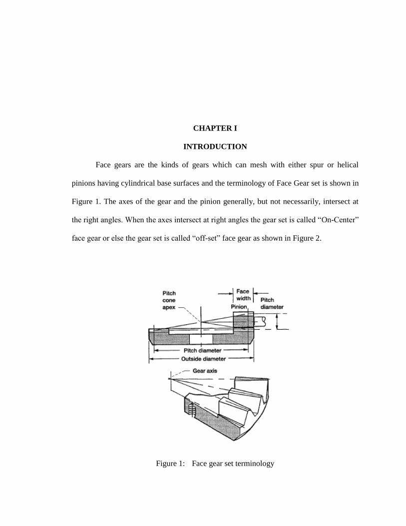
Face gears are the kinds of gears which can mesh with either spur or helical
pinions having cylindrical base surfaces and the terminology of Face Gear set is shown in
Figure 1. The axes of the gear and the pinion generally, but not necessarily, intersect at
the right angles. When the axes intersect at right angles the gear set is called “On-Center”
face gear or else the gear set is called “off-set” face gear as shown in Figure 2.
Figure 1: Face gear set terminology
2
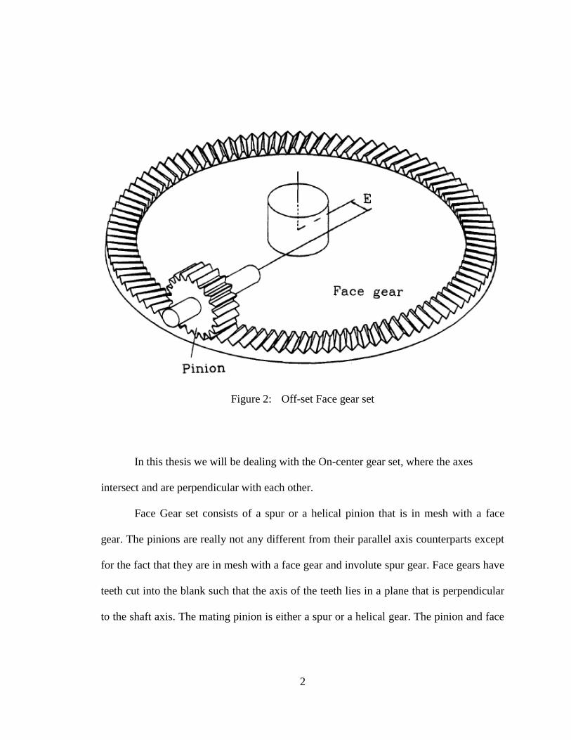
Figure 2: Off-set Face gear set
In this thesis we will be dealing with the On-center gear set, where the axes
intersect and are perpendicular with each other.
Face Gear set consists of a spur or a helical pinion that is in mesh with a face
gear. The pinions are really not any different from their parallel axis counterparts except
for the fact that they are in mesh with a face gear and involute spur gear. Face gears have
teeth cut into the blank such that the axis of the teeth lies in a plane that is perpendicular
to the shaft axis. The mating pinion is either a spur or a helical gear. The pinion and face

3
gear axes most often form a 90ᵒ
are possible. In operation, this type of gear is similar to
an equivalent set of straight gears.
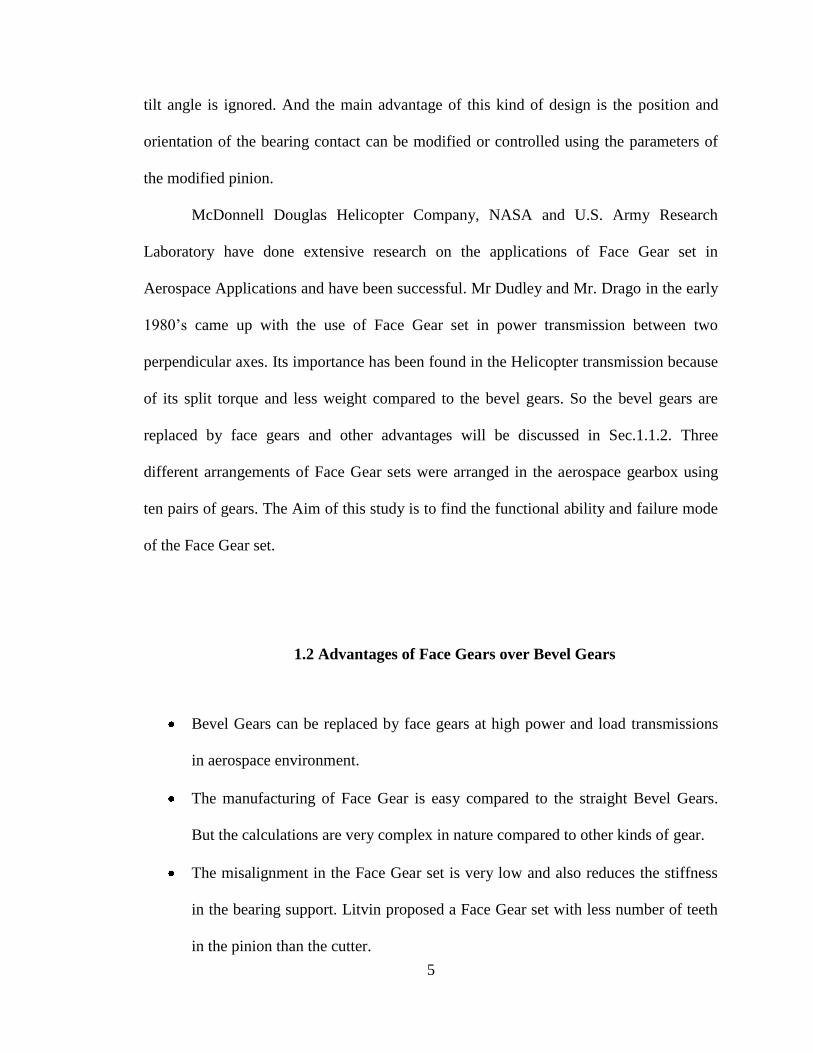
The face gear tooth changes shape from one end of the tooth along the radius of
the face of the gear as shown in Fig 3. The load capacity of face gearset, compared with
that of bevel gears, is less, thus they are used mostly used as motion transmission gears
rather than as power gears. Face gearsets arerelatively easy to make and less expensive
compared to the bevel gears. But the calculations involved in designing the face gear set
are more complex in nature, because of the change in face width, undercutting and
pointing. There were some initial works done in 1950's and 1960's in Russia [1] [2]. Also
a mojor contribution was done by Dudley in 1960's giving the formulaes which will be
discussed in the section 1.1.
Figure 3: Face gear teeth

4
1.1 Previous Works
Face gears were used for centuries in wagons by Chinese and power generation
by Romans [3, 4]. The invention if the modern type of face gear set was an invention of
the Fellows Company. The importance of face gears was recognized when it is proposed
to use in helicopter transmission because of its split torque and its less weight, which is a
major advantage for the flying objects.
Fellows Company has invented the face gear drive and it is initially called
“Cylkro Gear” by a Dutch company [4]. Darle W. Dudley[6][5], F.L.Litvin [2] [6] [7] [8]
[4], Bloomfield B. [11] [12] has contributed a lot in the development of Face Gear in
early stages. Which are followed by J.Chakraborty [13] [14], B.S Bhadoria [14] [13],
David G. Lewicki [15], Aleksandar M. Egelja [10]. The advanced research on Face Gears
was done by Crown Gear B.V. Company in Netherlands. The research was followed in
United States, Germany and Japan.
Litvin has published many works on Face Gear includingdesign of Face Gear
cutters, theoretical study of face gears by dividing into elemental parts and also designed
and performed stress analysis on symmetric and asymmetric face gear drives
[9].Litvinalso designed computer programs to perform design and analysis on any kind of
symmetric or asymmetric Face Gear drives.
Claudio Zanzi and Jose I. Pedrero [16] has also developed a modified geometry
and performed tooth contact analysis and stress analysis on the Face Gear set with a
double crowned pinion. These analyses are performed to find the bearing contact and
stresses throughout meshing of the pinion with the Face Gear, but during the analyses the
5
tilt angle is ignored. And the main advantage of this kind of design is the position and
orientation of the bearing contact can be modified or controlled using the parameters of
the modified pinion.
McDonnell Douglas Helicopter Company, NASA and U.S. Army Research
Laboratory have done extensive research on the applications of Face Gear set in
Aerospace Applications and have been successful. Mr Dudley and Mr. Drago in the early
1980‟s came up with the use of Face Gear set in power transmission between two
perpendicular axes. Its importance has been found in the Helicopter transmission because
of its split torque and less weight compared to the bevel gears. So the bevel gears are
replaced by face gears and other advantages will be discussed in Sec.1.1.2. Three
different arrangements of Face Gear sets were arranged in the aerospace gearbox using
ten pairs of gears. The Aim of this study is to find the functional ability and failure mode
of the Face Gear set.
1.2 Advantages of Face Gears over Bevel Gears
Bevel Gears can be replaced by face gears at high power and load transmissions
in aerospace environment.
The manufacturing of Face Gear is easy compared to the straight Bevel Gears.
But the calculations are very complex in nature compared to other kinds of gear.
The misalignment in the Face Gear set is very low and also reduces the stiffness
in the bearing support. Litvin proposed a Face Gear set with less number of teeth
in the pinion than the cutter.
6
Due to less weight if the Face Gears over bevel gears, the use of Face Gear has
been increased in the helicopter transmission.
1.3 My Contribution
As there are no standard formulae to obtain the Face Gear geometry named HyGears
has been used to generate the geometry of the Face Gear set. Using these geometrical
values from the HyGear, Face Gear tooth has been designed in Solidworks software.
After designing the Face Gear tooth the load was applied to the tip of the tooth and
bending stress was obtained using Solidworks simulation. The numerical results are
validated according to AGMA standards.
7
CHAPTER II
VALIDATION OF RESULTS FOR BENDING STRESS OFFACE GEAR
2.1 Validation Of Bending Stress Results Using Lewis Formula And Solidworks
Simulation AS Per AGMA Standards
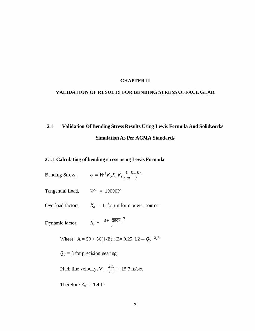
2.1.1 Calculating of bending stress using Lewis Formula
Bending Stress,
Tangential Load, = 10000N
Overload factors, = 1, for uniform power source
Dynamic factor, =
Where, A = 50 + 56(1-B) ; B= 0.25
= 8 for precision gearing
Pitch line velocity, V = = 15.7 m/sec
Therefore
8
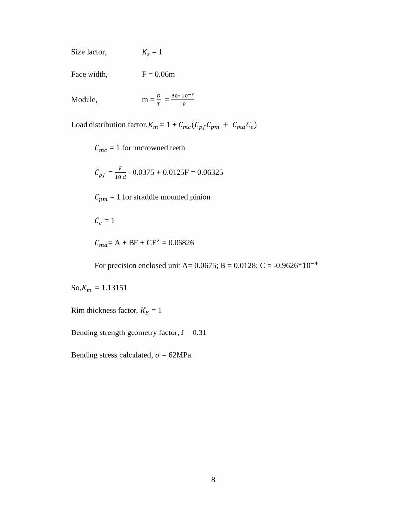
Size factor, = 1
Face width, F = 0.06m
Module, m = =
Load distribution factor, = 1 +
= 1 for uncrowned teeth
= - 0.0375 + 0.0125F = 0.06325
= 1 for straddle mounted pinion
= 1
= A + BF + C = 0.06826
For precision enclosed unit A= 0.0675; B = 0.0128; C = -0.9626*
So, = 1.13151
Rim thickness factor, = 1
Bending strength geometry factor, J = 0.31
Bending stress calculated, = 62MPa

9
2.1.2 Results from Solidworks Simulation
Maximum intensity stress from solidworks simulation = 66.6Mpa

10
2.1.3 Error percentage
Percentage error between the stress calculated from Lewis formula and Solidworks
Simulation,
Error Percentage = 7.4%
CHAPTER III
HYGEARS
3.1 Introduction To HyGears
HyGears is the Gear Processor(The High Performance Software for Gear
Engineering, Analysis and Production Control)
HyGears is an advanced and a 30 year old user friendly, 3D gear modeling
software that has been extensively tested in industry. Developed by Claude Gosselin,
Ph.D president of Involute Simulation Software Inc. and was initially developed in
September 1982 on a text only display main frame. It was first released to public in 1994
in Japan.
HyGears supports :
Spiral and hypoid gears for the Face Milling - Fixed Setting, Duplex Helical,
Modified Roll, Spread Blade, Formate and Helixform - cutting processes (all, The
Gleason Works)
It can also model the Face Hobbing process (Klingelnberg and Gleason)

12
Straight bevel gears (external and internal); straight bevels which can be „forged‟
and thus used to create forging dies
Spur and helical gears, external and internal, in planetary or offset arrangements
Involute splines and face gears
Figure 4: Planet gear developed using Hygears
Figure 5: Helical Bevel Gear
13
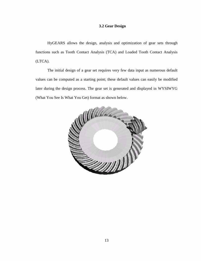
3.2 Gear Design
HyGEARS allows the design, analysis and optimization of gear sets through
functions such as Tooth Contact Analysis (TCA) and Loaded Tooth Contact Analysis
(LTCA).
The initial design of a gear set requires very few data input as numerous default
values can be computed as a starting point; these default values can easily be modified
later during the design process. The gear set is generated and displayed in WYSIWYG
(What You See Is What You Get) format as shown below.

14
Figure 6: Bevel gear compared to the real manufactured gear with the gear generated
using hygear
TCA ANALYSIS
The Transmission Error (TE) and the actual extent of the Bearing Pattern (BP),
unloaded and loaded, are readily accessed in graphic form, as shown below. E, P, G,
runout, alignment and shaft angle values may also be changed to see how a gear pair will
behave in different operating positions as imposed by manufacturing tolerances or
housing deformation under load.
In addition, E, P, G, alignment and shaft angle values may be modified in pairs to
produce a “map” of the expected behavior of a given gear pair over, say, a given
tolerance range.
Shown below is such a grid where E and P are modified in combinations.
Obviously, the E-P combinations along the diagonal from top-left to bottom-right are not
a problem; however, the E-P combinations along the top-right to bottom-left diagonal are
to be avoided.
15
LTCA ANALYSIS
The load and torque transmitted by neighbouring tooth pairs in mesh can be
established through the LTCA optional module. The associated bending and contact
stresses, bearing reactions, thermal-EHD oil film thickness, temperature increase and
scoring factor can be calculated and assessed in real time to ensure a sound design.
The axial and radial positions of meshing gear pairs, their alignment and shaft
angle can be modified to analyze “worst case” conditions, or to automatically produce
grid-like projections of the loaded behavior of a gear pair.
For example, in the figure below, the E and P values of a gear pair are modified to
produce E-P combinations allowing prediction of the Hertz contact stresses as the pinion
and gear relative position, because of gearbox deflection, manufacturing tolerances, or
else, displaces the contact pattern.
This Grid-like output can be applied to several combinations of relative positions
for gear pairs under load (LTCA). Support bearings and gearbox housing stiffness can be
accounted for in the LTCA such that the TE, BP, contact and fillet stresses are calculated
at the actual location under load.
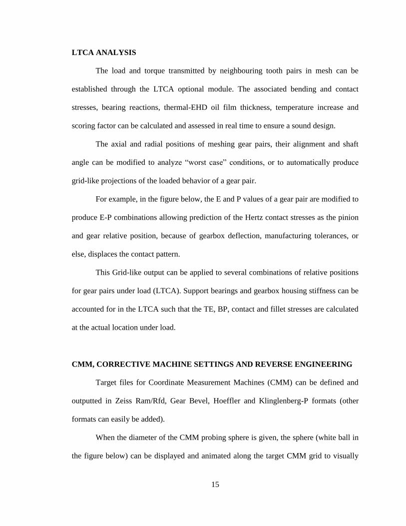
CMM, CORRECTIVE MACHINE SETTINGS AND REVERSE ENGINEERING
Target files for Coordinate Measurement Machines (CMM) can be defined and
outputted in Zeiss Ram/Rfd, Gear Bevel, Hoeffler and Klinglenberg-P formats (other
formats can easily be added).
When the diameter of the CMM probing sphere is given, the sphere (white ball in
the figure below) can be displayed and animated along the target CMM grid to visually

16
detect possible interference with the opposite tooth flank, or the toot root, as
measurement proceeds.
HyGEARS can import any text based CMM output file to calculate Corrective
Machine Settings, or to Reverse Engineer existing gearsets.
CMM results can also be used to estimate the TCA and LTCA behaviour of a real gear
pair, and thus allows the troubleshooting and improvement of problematic gear sets.
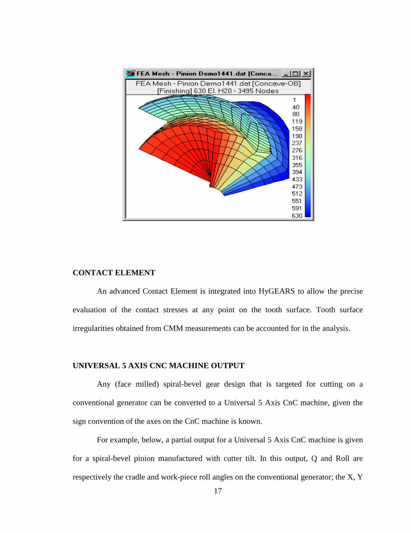
FEA PRE-PROCESSING AND FINITE STRIPS
HyGEARS offers advanced functions such as Finite Element Analysis pre-
processing (meshing and load application, left figure below), or the analysis of the gears
under load using the integrated Finite Strips (right figure below), a subset of the FEA.
17
CONTACT ELEMENT
An advanced Contact Element is integrated into HyGEARS to allow the precise
evaluation of the contact stresses at any point on the tooth surface. Tooth surface
irregularities obtained from CMM measurements can be accounted for in the analysis.
UNIVERSAL 5 AXIS CNC MACHINE OUTPUT
Any (face milled) spiral-bevel gear design that is targeted for cutting on a
conventional generator can be converted to a Universal 5 Axis CnC machine, given the
sign convention of the axes on the CnC machine is known.
For example, below, a partial output for a Universal 5 Axis CnC machine is given
for a spiral-bevel pinion manufactured with cutter tilt. In this output, Q and Roll are
respectively the cradle and work-piece roll angles on the conventional generator; the X, Y

18
and Z axis are conventional, i.e. X is horizontal and + towards the right when facing the
machine, Z is vertical and + upwards, and Y is perpendicular to X and Z and + going into
the machine; the B axis supports the turntable, and the C axis is the turntable holding the
work piece, and thus provides the roll angle of the work-piece on the CnC machine.
“STEP” OUTPUT
HyGEARS can directly export the topography of the pinion and gear teeth to any
STEP capable CAD/CAM system.
Thus, molds for plastic gears, electrodes for sintered gears, or simply CAD
models, can conveniently be obtained using the exact tooth topography.
For example, the left figure below shows a spiral-bevel pinion tooth in the
HyGEARS display; the topography of this tooth was exported in STEP format to a CAD
system, which is displayed in the right figure below.
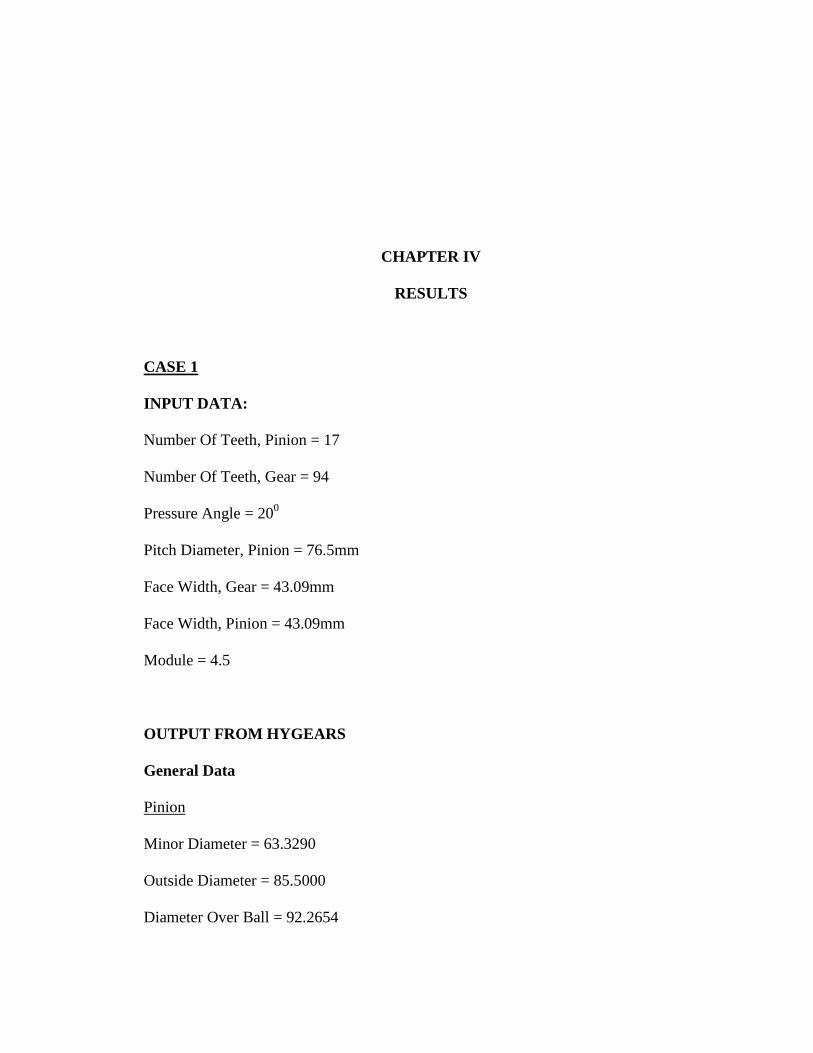
CHAPTER IV
RESULTS
CASE 1
INPUT DATA:
Number Of Teeth, Pinion = 17
Number Of Teeth, Gear = 94
Pressure Angle = 200
Pitch Diameter, Pinion = 76.5mm
Face Width, Gear = 43.09mm
Face Width, Pinion = 43.09mm
Module = 4.5
OUTPUT FROM HYGEARS
General Data
Pinion
Minor Diameter = 63.3290
Outside Diameter = 85.5000
Diameter Over Ball = 92.2654

20
Roller-Ball Diameter = 9.5250
Addendum Factor = 1.0000
Dedendum Factor = 1.1500
Fillet Factor = 0.2500
Addendum = 4.5000
Dedendum = 6.5856
Gear
Number Of Teeth = 94
Face Width = 43.0931
Inner Diameter = 398.04
Pitch Diameter = 423.0000
Outside Diameter = 498.2230
Addendum Factor = 1.0000
Dedendum Factor = 1.2500
Fillet Factor = 0.2500
Addendum = 4.4998
Dedendum = 6.3506

21
Blank Data
Pinion
Mean Helix Angle (Right) = 0.00.00
Mean Helix Angle (Left) = 0.00.00
Mean Press Angle (Right) = 19.59.28
Mean Press Angle (Left) = 19.59.27
Gear
Mean Helix Angle (Right) = 1.18.30
Mean Helix Angle (Left) = 1.18.29
Mean Press Angle (Right) = 29.07.19
Mean Press Angle (Left) = 29.07.19
Tooth Data
Pinion
Calculated Tooth Depths (Chordal):
Form Depth (Mid-F) = 7.0142
Whole Depth (Mid-F) = 11.6541
Calculated Tooth Depths (Circular):
Form Depth (Mid-F) = 6.8362
Whole Depth (Mid-F) = 11.0856
22
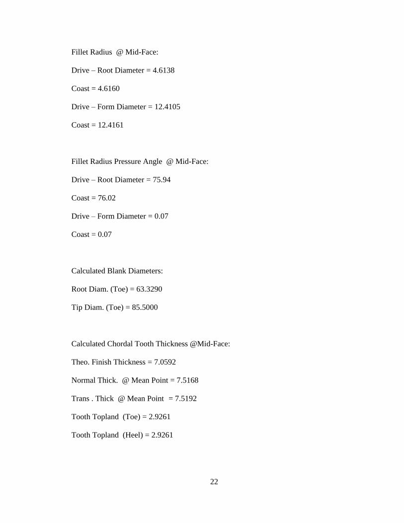
Fillet Radius @ Mid-Face:
Drive – Root Diameter = 4.6138
Coast = 4.6160
Drive – Form Diameter = 12.4105
Coast = 12.4161
Fillet Radius Pressure Angle @ Mid-Face:
Drive – Root Diameter = 75.94
Coast = 76.02
Drive – Form Diameter = 0.07
Coast = 0.07
Calculated Blank Diameters:
Root Diam. (Toe) = 63.3290
Tip Diam. (Toe) = 85.5000
Calculated Chordal Tooth Thickness @Mid-Face:
Theo. Finish Thickness = 7.0592
Normal Thick. @ Mean Point = 7.5168
Trans . Thick @ Mean Point = 7.5192
Tooth Topland (Toe) = 2.9261
Tooth Topland (Heel) = 2.9261

23
Gear
Calculated Tooth Depths (Chordal):
Form Depth (Mid-F) = 11.6627
Whole Depth (Mid-F) = 12.6810
Calculated Tooth Depths (Circular):
Form Depth (Mid-F) = 11.6620
Whole Depth (Mid-F) = 12.6799
Fillet Radius @ Mid-Face:
Drive – Root Diameter = 1.7199
Coast = 1.7199
Drive – Form Diameter = 9.7158
Coast = 9.7150
Fillet Radius Pressure Angle @ Mid-Face:
Drive – Root Diameter = 72.84
Coast = 72.84
Drive – Form Diameter = 29.11
Coast = 29.11
Calculated Chordal Tooth Thickness @Mid-Face:
Thoe . Finish Thickness = 14.0902
24
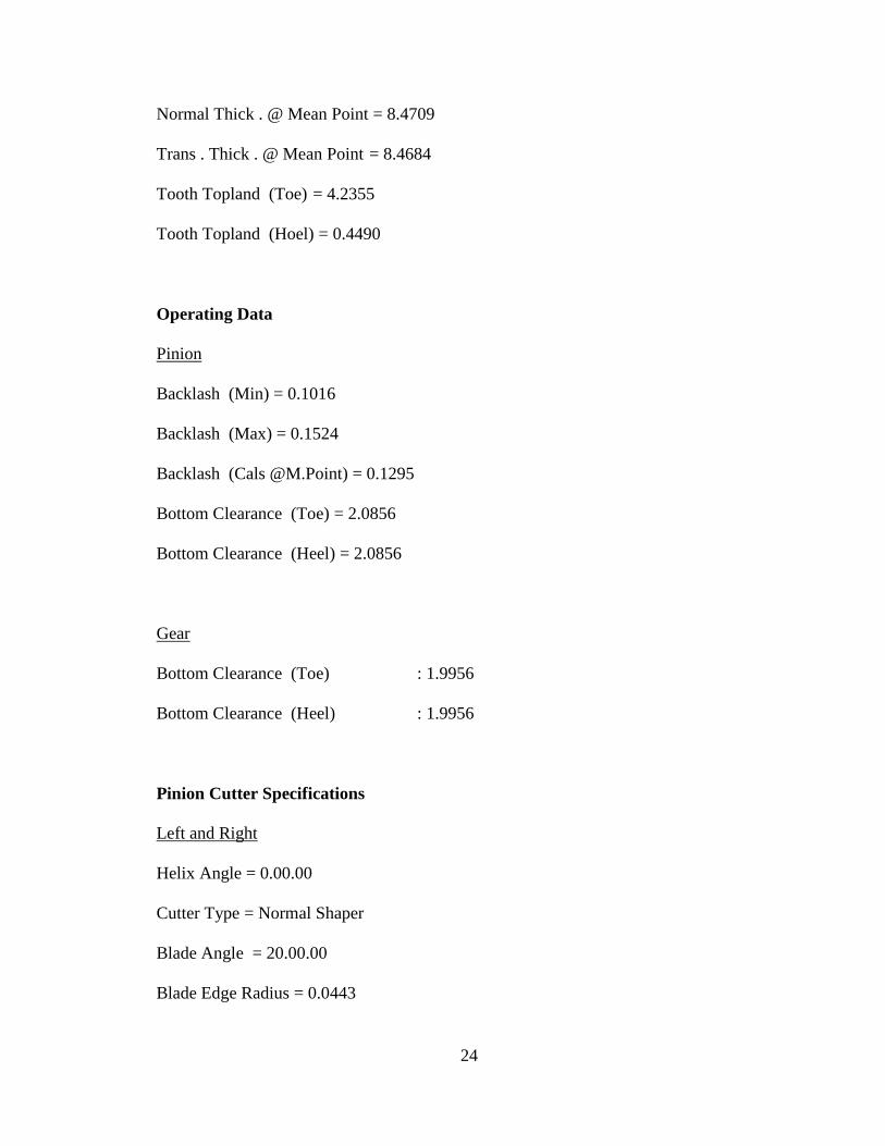
Normal Thick . @ Mean Point = 8.4709
Trans . Thick . @ Mean Point = 8.4684
Tooth Topland (Toe) = 4.2355
Tooth Topland (Hoel) = 0.4490
Operating Data
Pinion
Backlash (Min) = 0.1016
Backlash (Max) = 0.1524
Backlash (Cals @M.Point) = 0.1295
Bottom Clearance (Toe) = 2.0856
Bottom Clearance (Heel) = 2.0856
Gear
Bottom Clearance (Toe) : 1.9956
Bottom Clearance (Heel) : 1.9956
Pinion Cutter Specifications
Left and Right
Helix Angle = 0.00.00
Cutter Type = Normal Shaper
Blade Angle = 20.00.00
Blade Edge Radius = 0.0443
25
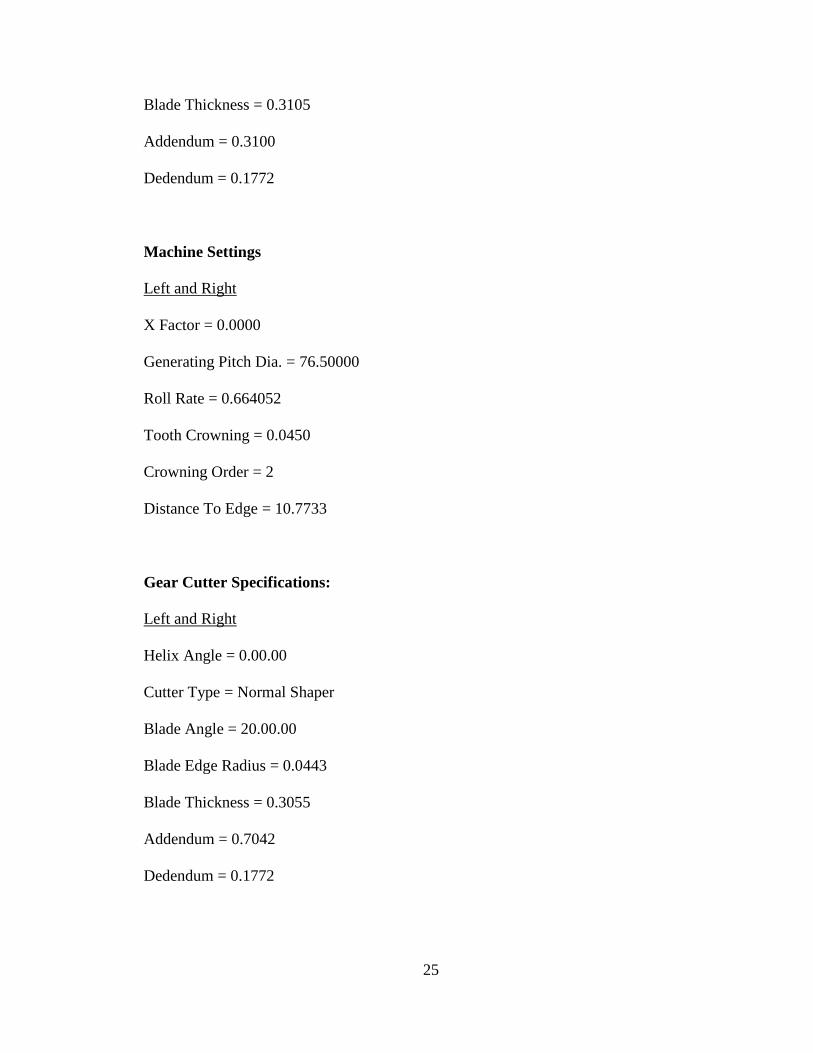
Blade Thickness = 0.3105
Addendum = 0.3100
Dedendum = 0.1772
Machine Settings
Left and Right
X Factor = 0.0000
Generating Pitch Dia. = 76.50000
Roll Rate = 0.664052
Tooth Crowning = 0.0450
Crowning Order = 2
Distance To Edge = 10.7733
Gear Cutter Specifications:
Left and Right
Helix Angle = 0.00.00
Cutter Type = Normal Shaper
Blade Angle = 20.00.00
Blade Edge Radius = 0.0443
Blade Thickness = 0.3055
Addendum = 0.7042
Dedendum = 0.1772

26
Machine Settings:
X Factor = 0.0000
Generating Pitch Dia. = 455.1299
Roll Rate = 0.111617
Tooth Crowning = 0.0000
Crowning Order = 1
Distance To Edge = 0.0000

27
28
29
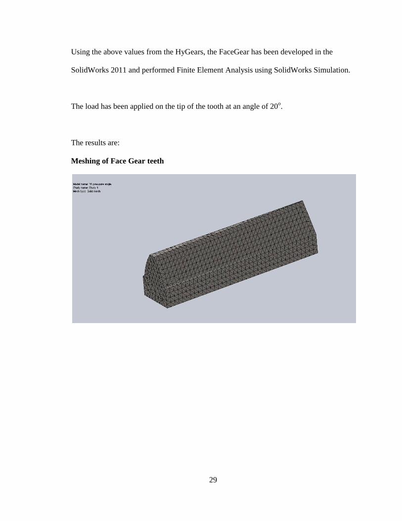
Using the above values from the HyGears, the FaceGear has been developed in the
SolidWorks 2011 and performed Finite Element Analysis using SolidWorks Simulation.
The load has been applied on the tip of the tooth at an angle of 20o.
The results are:
Meshing of Face Gear teeth
30
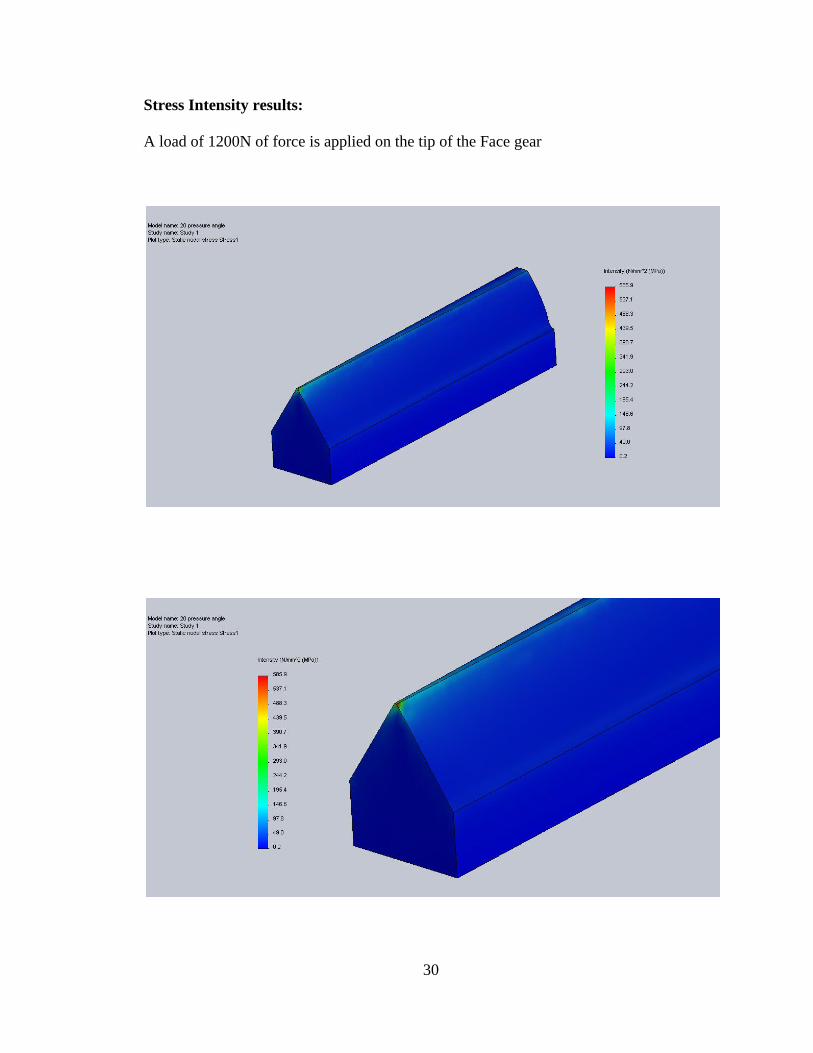
Stress Intensity results:
A load of 1200N of force is applied on the tip of the Face gear
31
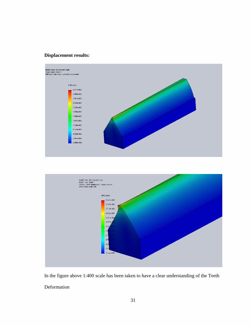
Displacement results:
In the figure above 1:400 scale has been taken to have a clear understanding of the Teeth
Deformation
32
CASE 2
INPUT DATA:
Number Of Teeth, Pinion = 17
Number Of Teeth, Gear = 94
Pressure Angle = 250
Pitch Diameter, Pinion = 76.5mm
Face Width, Gear = 43.09mm
Face Width, Pinion = 43.09mm
Module = 4.5
OUTPUT DATA FROM HYGEARS:
Pinion
Minor Diameter = 64.8907
Pitch Diameter = 76.5000
Out Side Diameter = 85.5000
Diameter Over Ball = 92.6465
Roller-Ball Diameter = 9.7790
Addendum Factor = 1.0000
Dedendum Factor = 1.1500
Fillet Factor = 0.2500
Addendum = 4.5000

33
Dedendum= 5.8048
Gear
Inside Diameter = 398.04
Pitch Diameter = 423.0000
Out Side Diameter = 484.2216
Addendum Factor = 1.0000
Dedendum Factor = 1.2500
Fillet Factor = 0.2500
Addendum = 4.5001
Dedendum = 5.4498
Blank Data
Pinion
Mean Helix Angle (Right) = 0.00.00
Mean Helix Angle (Left) = 0.00.00
Mean Helix Angle (Right) = 24.59.32
Mean Press Angle (Left) = 24.59.31
Gear
Mean Helix Angle (Right) = 0.44.48
Mean Helix Angle (Left) = 0.44.49
Mean Helix Angle (Right) = 29.38.29
34
Mean Press Angle (Left) = 29.38.29
Tooth Data
Pinion
Calculated Tooth Depths (Chordal):
Form Depth (Mid - F) = 7.8586
Whole Depth (Mid - F) = 10.8479
Calculated Tooth Depths (Circular):
Form Depth (Mid – F) = 7.6189
Whole Depth (Mid – F) = 10.3048
Fillet Radius & Mid – Face:
Drive – Root Diameter = 3.7126
Coast = 3.7096
Drive – Form Diameter = 9.8940
Coast = 9.8953
Fillet Radius Pressure Angle & Mid – Face:
Drive – Root Diameter = 71.87
Coast = 71.80
Drive – Form Diameter = 9.47
Coast = 9.47

35
Calculated Blank Diameters:
Root Diam. (Toe) = 64.8907
Tip Diam. (Toe) = 85.5000
Calculated Chordal Tooth Thickness & Mid – Face:
Theo. Finish Thickness = 7.0588
Normal Thick . &Mean Point = 7.5092
Trans. Thick. & Mean Point = 7.5110
Tooth Topland (Toe) = 2.1006
Tooth Topland (Heel) = 2.1006
Gear
Calculated Tooth Depths (Chordal):
Form Depth (Mid - F) = 10.6913
Whole Depth (Mid - F) = 11.7642
Calculated Tooth Depths (Circular):
Form Depth (Mid – F) = 10.6908
Whole Depth (Mid – F) = 11.7632
Fillet Radius & Mid – Face:
Drive – Root Diameter =1.8584
Coast =1.8584

36
Drive – Form Diameter = 10.1929
Coast = 10.1950
Fillet Radius Pressure Angle & Mid – Face:
Drive – Root Diameter =72.23
Coast = 72.23
Drive – Form Diameter = 29.60
Coast =29.60
Calculated Chordal Tooth Thickness & Mid – Face:
Theo. Finish Thickness =13.8215
Normal Thick . &Mean Point = 7.5528
Trans. Thick. & Mean Point = 7.5502
Tooth Topland (Toe) = 3.6221
Tooth Topland (Heel) = 0.1341
Operating Data
Pinion
Backlash (Min) = 0.1016
Backlash (Max) = 0.1524
Backlash (Calc&M.Point) = 0.1337
Bottom Clearence (Toe) = 1.3046
Bottom Clearance (Heel) = 1.3046

37
Gear
Bottom Clearence (Toe) = 1.0961
Bottom Clearance (Heel) =1.0961
Pinion Cutter Specifications
Left and Right
Helix Angle = 0.00.00
Cutter Type = Normal Shaper
Blade Angle = 25.00.00
Blade Edge Radius = 0.0443
Blade Thickness = 0.3196
Addendum = 0.3100
Dedendum = 0.1772
Machine Settings
X Factor = 0.0000
Generating Pitch Dia. = 76.5000
Roll Rate = 0.664052
Tooth Crowning = 0.0450
Crowning Order = 2
Distance To Edge = 10.7733

38
Gear Cutter Specifications
Left and Right
Helix Angle = 0.00.00
Cutter Type = Normal Shaper
Blade Angle = 25.00.00
Blade Edge Radius = 0.0443
Blade Thickness = 0.3146
Addendum = 0.7042
Dedendum = 0.1772
Machine Settings
X Factor = 0.0000
Generating Pitch Dia. = 441.1284
Roll Rate = 0.115159
Tooth Crowning = 0.0000
Crowning Order = 1
Distance To Edge = 0.0000
39
40

41
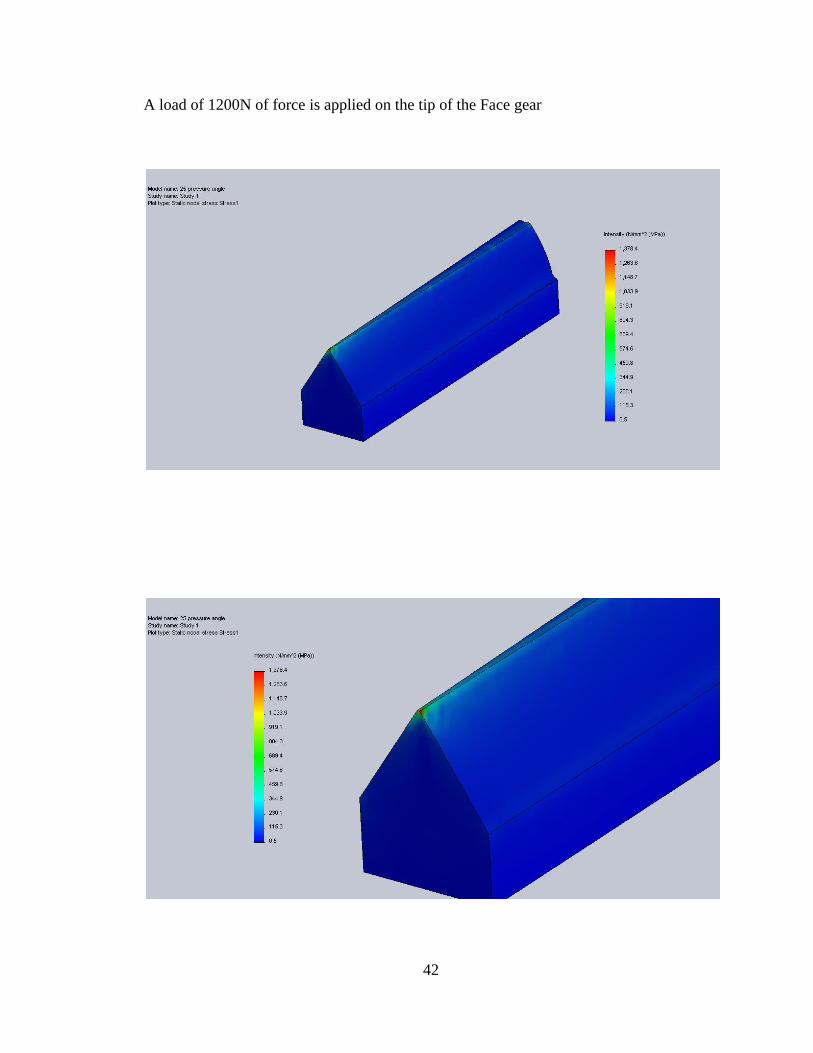
Using the above values from the HyGears, the FaceGear has been developed in the
SolidWorks and performed Finite Element Analysis using SolidWorks Simulation.
The load has been applied on the tip of the tooth at an angle of 25o.
The results are:
After Meshing:
42
A load of 1200N of force is applied on the tip of the Face gear

43
Displacement Results:
In the figure above 1:400 scale has been taken to have a clear understanding of the Teeth
Deformation

CHAPTER V
CONCLUSION AND FUTURE SCOPE
5.1 Conclusion
1. Finite Element method can be successfully used to predict bending stress of a typical
Face Gear set
2. The percentage error between AGMA formula and from solidworks for an involute
spur gear about 7.4%
3. The geometry can be generated with one face(inner face) of a regular involute spur
gear and a point edge on the other face(outer face)
4. The bending stress has been obtained from Solidworks Simulation for two different
gears of 20o and 25
o pressure angle.
5. The result of this study can be used to size a face gear set for a given operating
condition (transmitted power at a given speed) and the bending stress on the tooth
can be determined

45
5.2 Future Scope
1. Contact stress can also determined for the Facegear
2. Experimental validation of the results predicted by AGMA formula and the Finite
element analysis presented in this work
3. Because of the high torque and high loads during operation, considerable amounts of
heat is also dissipated. So the heat transfer condition can also be considered in the
future analysis of the Facegear.

46
BIBLIOGRAPHY
[1] Y. Davidov, Non-Involute Gears, Mashgis, 1950 (in Russian).
[2] F. L. Litvin, Theory of Gearing, Nauka, 1968 (in Russian).
[3] S. Beermann and U. Kissling, "Face Gears: Geometry and strength," Gear
Technology, pp. 54-61, Jan/ Feb 2007.
[4] F. L. Litvin, "Development of gear technology and theory of gearing," NASA
Reference Publication 1406, 1997.
[5] "Cylkro Face Gear," Nov/Dec 2010. [Online]. Available: www.geartechnology,com.
[Accessed July 2011].
[6] D. W. Dudley, Gear handbook. The design, manufacture, and the application of
gears, New York: McGraw- Hill , 1962.
[7] D. Dudley, Handbook of Practical Gear Design, McGraw-Hill, 1984.
[8] F. L. Litvin, Gear Geometry and Applied Theory, Prentice Hall, 1994.
[9] F. L. Litvin, "Handbook of Face Gear Drives with a Spur Involute Pinion," NASA
Final Contractor Report, 2000.
[10] L. F. Litvin and A. E. Aleksandra, "Computerized design, generation and simulation
of meshing of orthogonal offset face-gear drive with a spur involute pinion with
localized bearing contact," Mech. Math. Theory, vol. 33, no. 1/2, pp. 87-102, 1998.
47
[11] B. Bloomfield, "Design of Face Gears," Mach Des., vol. 19, no. 4, pp. 129-134,
1947.
[12] Bloomingfield, "Alignment charts of face gears," in Product Engineering, 1952, p.
187.
[13] J. Chakraborty and B. S. Bhadoria, "Some studies on Hypoid Face Gears,"
Mechanism and machine theory, vol. 8, pp. 339-349, 1973.
[14] J. Chakraborty and B. S. Bhadoria, "Design of Face Gears," Mechanisms, vol. 6, pp.
435-445, 1971.
[15] D. G. Lewicki and R. F. Handschuh, "Evaluation of Carburized and Ground Face
Gears," NASA; US ARL, Quebec, 1999.
[16] C. Zanzi and J. I. Pedrero, "Application od modified geometry of face gear drive,"
Elsevier, vol. 194, pp. 3047-3066, 2005.
[17] F. V. and S. J., "Face gear deisgn factors," in Gear design and applications, N. P.
Chironis, Ed., McGraw-Hill, 1967.