Embed Size (px)
Citation preview

A Fingerprint Identification System
By
Jean-Christophe Petkovich
A thesis proposal submitted to
the Faculty of Graduate Studies and Postdoctoral Affairs
in partial fulfilment of
the requirements for the degree of
Master of Computer Science
Ottawa-Carleton Institute for Computer Science
School of Computer Science
Carleton University
Ottawa, Ontario
November 2011
© Copyright
2011, Jean-Christophe Petkovich

Library and Archives Canada
Published Heritage Branch
Bibliotheque et Archives Canada
Direction du Patrimoine de I'edition
395 Wellington Street Ottawa ON K1A0N4 Canada
395, rue Wellington Ottawa ON K1A 0N4 Canada
Your file Votre reference
ISBN: 978-0-494-87824-8
Our file Notre reference
ISBN: 978-0-494-87824-8
NOTICE:
The author has granted a nonexclusive license allowing Library and Archives Canada to reproduce, publish, archive, preserve, conserve, communicate to the public by telecommunication or on the Internet, loan, distrbute and sell theses worldwide, for commercial or noncommercial purposes, in microform, paper, electronic and/or any other formats.
AVIS:
L'auteur a accorde une licence non exclusive permettant a la Bibliotheque et Archives Canada de reproduire, publier, archiver, sauvegarder, conserver, transmettre au public par telecommunication ou par I'lnternet, preter, distribuer et vendre des theses partout dans le monde, a des fins commerciales ou autres, sur support microforme, papier, electronique et/ou autres formats.
The author retains copyright ownership and moral rights in this thesis. Neither the thesis nor substantial extracts from it may be printed or otherwise reproduced without the author's permission.
L'auteur conserve la propriete du droit d'auteur et des droits moraux qui protege cette these. Ni la these ni des extraits substantiels de celle-ci ne doivent etre imprimes ou autrement reproduits sans son autorisation.
In compliance with the Canadian Privacy Act some supporting forms may have been removed from this thesis.
While these forms may be included in the document page count, their removal does not represent any loss of content from the thesis.
Conformement a la loi canadienne sur la protection de la vie privee, quelques formulaires secondaires ont ete enleves de cette these.
Bien que ces formulaires aient inclus dans la pagination, il n'y aura aucun contenu manquant.
Canada
Abstract
Identification and authentication are extremely important tasks as we continue to
move into a more information-oriented age. Authentication is becoming necessary for
two of the main devices used by nearly everyone today, i.e., laptops/netbooks and
cellphones. Identification is becoming an increasingly difficult problem as more and
more methods become available to falsify identity.
The use of biometrics is one potential (or partial) solution to both these problems.
There are several different possible biometrics that could be of use for either of the
above tasks, but few of them have been as widely used, or as closely studied, as
fingerprints. This is due to their excellent metrics when it concerns many biometric
performance criteria. The permanence, uniqueness and universality of fingerprints
make them ideal candidates for use as biometrics.
Fingerprint matching and recognition are extremely difficult problems. Several
different important factors are to be considered when attempting to find a fingerprint
match, and of them, the most important are distortions. These potential distortions
significantly increase the complexity of matching or recognition. A noisy fingerprint
can contain a number of different types of distortion including rotation, displacement,
distortion due to skin plasticity, variance in pressure when the print is taken, condition
of the skin when the print is taken, and the noise caused by the equipment (for
example, as a result of the use of older fingerprint collection techniques).
Fingerprint matching, along with other biometric matching techniques, follows a
relatively well-established process streamlined as follows: collection, pre-processing,
extraction, and finally matching. The focus of this thesis is the comparison of different
techniques centered around the matching of minutiae. In this research endeavor, we
have studied all the associated processes with achieving this. Besides, we have also
developed a fully-functioning prototype system to collect fingerprints, pre-process
them, extract minutiae, and to finally compare and combine several different matching
techniques. Finally, we will be able to accomplish a comparison of existing techniques

based on the minutia-matching paradigm that also incorporates noisy subsequence
tree comparisons.
ii

Acknowledgments
Firstly, I would like to thank Prof. John Oommen for accepting me into his lab, for
his support and expertise. His experience and methodical approach were invaluable
in the development of this thesis.
I would also like to thank my family for all their love and support, without which I
would surely not have been able to complete this thesis. In particular, I would like to
thank my mother and father for their encouragement and valuable guidance. I would
also like to thank my sister for her support and her assistance during this period.
Finally, I would like to thank Carleton's School of Computer Science. I have met
some brilliant and exceptional people, and I have also learned much since my arrival
here two years ago. The people I have met here have shaped both my interests and
ambitions, and will likely have a great impact on the rest of my life.
i
Contents
1 Introduction 1
1.1 Motivations and Objectives 1
1.2 Problem Statement 2
1.3 Contributions 4
1.4 Scope 7
1.5 Outline 7
2 Background: Survey of the Field 9
2.1 What is a Biometric System? 9
2.2 Significant Properties and Trade-offs of Biometric Systems 11
2.2.1 Verification vs. Identification 12
2.2.2 Automated vs. Attended 13
2.2.3 Trade-off: Matching Speed vs Accuracy 13
2.2.4 Trade-off: Biometric Types 14
2.3 Why Fingerprints are Effective Biometrics 16
2.4 Fingerprint Distinctiveness and Validity/Accuracy as a Biometric . . 17
2.4.1 Admissibility in Court 19
2.5 Biology of Fingerprint Uniqueness 19
2.6 The Fingerprint Identification Process 20
2.6.1 Raw Data Collection 20
2.6.2 Data Enhancement 24
2.6.3 Feature Extraction and Template Construction 25
2.6.4 Minutia Matching 30
ii
2.7 Non-Minutia-based Matching Techniques 33
2.7.1 Refining Results 34
2.8 Chapter Summary 34
3 Image Processing Aspects 36
3.1 Adding Artificial Noise 37
3.1.1 Convolution with Arbitrary Kernels 39
3.1.2 Pixel-Damage-Based Noise 39
3.1.3 Additive Gaussian Noise 40
3.2 Image Enhancement Methods 42
3.2.1 Gaussian Blur 42
3.2.2 Contrast Adjustment and Normalization 42
3.2.3 Gabor-Filtering-Based Fingerprint Image Enhancement .... 43
3.3 Additional Image Processing Tools Used 44
3.4 Chapter Summary 45
4 File Format Considerations 46
4.1 Importance of Compression 46
4.2 Problems with Pre-Existing Image Compression Techniques 47
4.3 Wavelet Scalar Quantization Compression 47
4.4 File Formats Used in The Developed System 50
4.5 Chapter Summary 51
5 Pattern Recognition Methods 52
5.1 Survey of Global Matching Techniques 52
5.1.1 Hough Transform 53
5.1.2 Ridge Feature Alignment Approach 53
5.2 Survey of Local Matching Techniques 54
5.2.1 Feature-Vector Based Matching 54
5.2.2 Adjacency Graph Matching 55
5.2.3 Geometric Clustering-Based Matching 55
5.3 Implemented Recognition Methods 56
iii
5.3.1 Development Notes 56
5.3.2 Global-Scheme: Hough Transform Alignment-based Matching 57
5.3.3 Local-Scheme: K-plet Representation Matching 64
5.3.4 Local-Scheme: Bozorth's Algorithm 68
5.4 Chapter Summary 70
6 Subsequence-Tree-Based Methods 71
6.1 Noisy Subsequence Tree Recognition Problem 71
6.1.1 NSTRP and Fingerprint Matching Problem Similarities .... 72
6.2 Adapting Noisy Subsequence Tree Recognition 76
6.2.1 Encoding Minutiae and Their Local-Spatial-Relationships ... 77
6.2.2 Noise Considerations 80
6.3 Subsequence Algorithm Performance 81
6.4 Using Artificial Noise 82
6.4.1 Results Analysis/Future Work 83
6.5 Chapter Summary 85
7 Overall System 86
7.1 System Features 88
7.2 Design Process/Rationale 88
7.2.1 Fingerprint Library 90
7.2.2 The Piping Mechanism 91
7.2.3 Combined Components 92
7.3 System Components 93
7.3.1 Raw Data Collection Phase 94
7.3.2 Data Enhancement Phase 94
7.3.3 Feature Extraction Phase and Template Construction 95
7.3.4 Minutia Matching Phase 96
7.4 Usage Examples 96
7.5 Chapter Summary 99
iv

8 Conclusions 100
8.1 Thesis Summary 100
8.2 Summary of Contributions 101
8.3 Summaxy of Conclusions 103
8.4 Future Work 104
Bibliography 105
v

List of Figures
2.1 General structure of a fingerprint scanner. Drawn from a description
reported in [1] 24
2.2 Illustration of an orientation window on a group of ridges with similar
6 values. Diagram similar to that in [2] 28
2.3 The different types of minutiae. Prom left to right, are the ridge bifur
cation minutia, the ridge-ending minutia, and the short ridge minutia. 30
2.4 The minutiae on this fingerprint have been highlighted with red squares,
the blue line indicates the direction of the most closely associated ridge,
this is known as the minutia's 6 value 31
3.1 Examples of the different types of noise which can be applied. Prom left
to right and top to bottom, we have the original image, the image with
Gaussian additive noise applied, the image with pixel damage (salt
and pepper) noise applied, and finally with Gaussian blur (convolution
with a Gaussian Kernel) applied 38
4.1 Examples showing the effects of two different image compression types.
In the left panel is a fingerprint image compressed using standard JPEG
compression and in the right panel the same image compressed using
the FBI's standard WSQ compression. The compression algorithms
were tuned to the same compression ratio. The magnified portion of
the left image shows the blocks produced by the JPEG compression
algorithm. (Note: The effect may not be as pronounced in some PDF-
readers due to image processing performed by these applications.) . . 49
vi
5.1 Diagram showing the alignment produced by Algorithm 5. The top
two images depict the two fingerprints, from the same digit, with their
detected minutiae, and the bottom image is the resulting alignment
between the two sets of minutiae. One set of the minutiae is coloured
green with its 9 indicator coloured orange, while the other set of minu
tiae is coloured red with its 0 indicator coloured blue 59
6.1 Diagram illustrating the concentric circles which define the levels of
the minutia tree. The minutiae are highlighted with red squares, the
angle of the most closely associated ridge is indicated with a blue line,
and the child-parent relationships are shown in green 78
6.2 Diagram illustrating what occurs when one of the bands formed by the
concentric circles is empty. The empty band is highlighted in pink,
and is joined with the next smallest concentric circle indicated with a
dot ted l ine . These two now form the f i r s t leve l ( root ) of the t ree . . . . 80
7.1 Diagram illustrating the overall system, shows each stage and the file-
type/state of the information as it moves through the system 87
7.2 Diagram of the fingerprint class, showing the main externally-visible
fields of the class 91
7.3 Usage examples of basic interactions with the "afis" command-line util
ity including: matching a file against a database, registering a file and
then matching it against the database and garbling the image prior to
matching 97
7.4 Usage examples of several more advanced options of the "afis" util
ity including: selection of the matching algorithm(s), specifying noise
options, specifying options to the garbling algorithms 98
7.5 Usage examples of supplying different algorithms for pre-processing
and feature extraction 98
vii
Chapter 1
Introduction
1.1 Motivations and Objectives
Fingerprint matching analysis has been a useful measure of identity and authenticity
for over 2,000 years, first in China as a method of authenticating documents [3].
Fingerprint identification and verification is based on the assumption that no two
individuals share identical fingerprint patterns [3]. Fingerprint ridge and pore pat
terns (in whole or in part) can be transferred to solid surfaces by deposition of contact
residue comprised of skin cells, oil, salt and moisture, or optically captured to provide
a two-dimensional representation [3]. Such representations can be stored indefinitely
in photographic or digital form, facilitating comparison against fingerprint archives.
The process of determining a fingerprint match entails the evaluation of spatially dis
tributed components of fingerprints that are in alignment as opposed to those that
are not.
The processes involved in the gathering and storage of prints generate distortions,
artifacts and noise which need to be managed so as to increase the accuracy and pre
cision of any fingerprint matching system [4]. Very often, only partial representations
of the prints are available, further increasing the complexity of the pattern matching
process. Although fingerprint recognition is a well-studied problem, matching highly
fragmented fingerprints is a very difficult problem, and is widely considered to be
unsolved [1].
1
CHAPTER 1. INTRODUCTION 2
The objectives of this thesis encompassed three main tasks. First, we decided
to develop a detailed study of biometric systems, including the design, specification
and construction of a complete fingerprint recognition system. Such a system could
be viewed as a "pipeline" of data which has a number of components characterizing
its functionality. We had to understand, then collect or design and implement all
the necessary components, or modules, of the final system. The modules involved in
cluded raw data collection, image processing and enhancement, feature extraction and
template construction, and finally minutia matching. In addition to the components
and functionality typically included in a fingerprint recognition system, we wished to
create a reusable and flexible fingerprint recognition system which could be extended
to the user's/developer's liking. The construction of a fingerprint recognition system,
as well as the task of studying and implementing several different algorithms available
in the literature, provided us with insight into the issues related to our next task -
the implementation of a new approach to fingerprint matching.
We wished to adapt the noisy subsequence recognition algorithm reported in [5]
to the fingerprint recognition problem. Previously, the noisy subsequence recognition
algorithm performed exceptionally well on a synthetic problem which bore a striking
resemblance to the fingerprint recognition problem. This motivated us to attempt to
adapt the algorithm to the fingerprint matching problem.
Third, and finally, we needed to evaluate the performance of our novel pioneering
algorithm against that of other well known fingerprint matching algorithms.
1.2 Problem Statement
Before we proceed, it is useful to precisely define the requirements and the components
of a fingerprint recognition system. These components represent different phases of
the fingerprint matching process, each of which play an important role in the accurate
matching of fingerprints. These components include the following:
1. Raw Data Collection: Given a physical finger, the component should be
able to produce either an image of the rolled or pressed impression of the finger,
referred to as a fingerprint image, I. I is often a simple array of pixel intensities.
CHAPTER 1. INTRODUCTION 3
2. Fingerprint Image Enhancement: From /, this component should be able
to produce an enhanced fingerprint image, E. E may either be masked with
a quality map or could have been enhanced for the purposes of fingerprint
matching. Enhancements which typically occur are either contrast adjustment
and ridge thinning, or ridge recovery through Gabor filtering.
3. Feature Extraction: Feature extraction involves the conversion of the en
hanced fingerprint image, E, into quantitative data regarding its ridge features.
This data is usually associated with specific locations referred to as minutiae.
The term "minutia" is used to refer to small ridge details found in fingerprints;
most often, they are a set of characterizing points described on ridge structures1.
The component should output a set of minutiae or similar features, M, which
is also commonly referred to as a template2.
4. Feature Matching3: The matching phase concerns itself with the fingerprint
matching problem, and is described in detail below.
The fingerprint matching problem itself is slightly more complex than the prob
lems tackled in the other phases listed above. As an understanding of the fingerprint
matching problem will be critical to the appreciation of the central problem of iden
tification/authentication through fingerprints, a definition of the problem is provided
below.
Given a database of fingerprint minutiae sets V = {Mi, M ? , . . . , M d } , determine
which fingerprints, if any, are from the same digit as a probe fingerprint minutiae set
V. Associated with this central question are a number of different sub-problems, or
approaches, which are more specific, the most common of which is the "fingerprint
minutia matching problem".
The fingerprint minutia-matching problem is given greater focus in this thesis as
it has become the ade facto standard" for fingerprint matching [4].
^he most common features and their associated metrics are detailed in Chapter 2 (Section 2.6.3). 2Fingerprint templates may also hold meta-data such as the known source of the fingerprint, but
this meta-data is not strictly necessary. 3Also referred to as the minutia-matching phase.
CHAPTER 1. INTRODUCTION 4
The minutia-matchlng problem can be defined as follows: Let V and Q be two
sets of minutiae each representing separate fingerprints:
"P = {Pi, where each ^ = {a!,a2,...,afc}
Q = {<7i, 92, •••, Q n } , where each = {&i, b 2 , . . . , b k } ,
where m is the number of minutiae discovered in the fingerprint associated with V,
n is the number of minutiae discovered in the fingerprint associated with Q, a and b
are minutia attributes, and k is the number of different minutia attributes.
Minutiae pi and $ are considered to match if their attributes are within a certain
threshold4. Further, two fingerprints are reckoned to be "matching" if their computed
"matching score", which is most often a function of the number of matched minutiae
between them, attains or exceeds a defined threshold.
While this is a basic formulation of the problem, one should understand that as
there is significant noise involved in fingerprint matching, there are many different
methods for computing whether two minutiae match, and further, if two fingerprints
themselves match.
For the purposes of this thesis, we will refer to the fingerprint matching problem
as the "general fingerprint matching problem" and to the more restricted fingerprint
minutiae matching problem as the "fingerprint matching problem"5.
1.3 Contributions
The research process reported in this thesis has led to a number of contributions.
The first is the design and implementation of a comprehensive, flexible, high-level
fingerprint recognition library. The library is composed of several different tools
4As we shall see later, this is an oversimplified model as there are a number of methods that do not conform to this problem specification, and so perform various transformations on the minutiae sets in order to match them together. However, this model remains useful as an illustration of the central fingerprint matching problem.
5There are a number of different physical features used to match fingerprints, but matching based on minutiae is, as mentioned, the de facto standard.

CHAPTER 1. INTRODUCTION 5
and modules. Where possible, the use of already-existing open source software tools
and libraries for use with fingerprint recognition were used, avoiding duplication of
previous efforts. The library is easily scriptable, providing a high-level interface to
the fingerprint recognition process, and is extensible through both calls to the system
shell and also the several dynamic library interfaces available in Python (e.g., ctypes).
All the details involving the conversion between image formats, the decoding of WSQ
files, and extracting minutia data are hidden from the user.
The processing that is hidden from the user by our library encompasses three out
of the four main components of a fingerprint matching system, namely, the collection
of the raw data, fingerprint image enhancement and feature extraction.
The raw data collection is handled by the library through the use of the open
source fingerprint scanner library "fprint". Although supported by our library, in
order to avoid the manual collection of large enough quantities of fingerprints for
testing, we procured several databases of fingerprints from the FVC2000 and FVC2002
fingerprint competitions. In addition to the collection of raw fingerprint images, it
is essential to be able to convert between different image formats in order to take
advantage of open source software6. Most of the available open source tools for
fingerprint recognition use either the WSQ, JPEG, TIFF, or PNG image files as their
input or output. We have used the "cwsq", "dwsq", and "PIL" tools/modules to
enable the conversion of our database images into the other formats. The details of
all these issues are described in Chapter 4 of the thesis.
The enhancement provided by our library includes contrast normalization and
a heuristic to determine the quality of disparate regions of the fingerprints. This
functionality was added through the use of the "mindtct" program.
Feature extraction is pivotal to the function and performance of a fingerprint
recognition system. The fingerprint ridge-features used by our library are primarily
the minutiae. Extraction is performed through the use of the "mindtct" program. In
our library, we support two different minutia file-types: XYT and MIN files. The XYT
files contain less information but are smaller, and consequently, they are simpler to
6As tools are often designed for a specific input format, the flexibility to convert between as many formats as possible permits choosing from a larger set of potential tools.

CHAPTER 1. INTRODUCTION 6
parse whereas MIN files store many diverse pieces of data about each minutia. These
details are again explained in Chapter 4.
The library also offers parallelism by executing individual matching processes
between two fingerprints in parallel. It is not necessary for the user to enable or
configure this feature as it is applicable to all fingerprint matching techniques.
In addition to the fingerprint library, we have created a complete fingerprint recog
nition system. As with the fingerprint library from which it was constructed, our
fingerprint recognition system is scriptable, extensible and capable of parallelism.
This fingerprint recognition system which we have developed is capable of con
structing arbitrary hierarchical fingerprint matching systems by permitting the "pip
ing" of results from one algorithm to another. This allows a user to take advantage of
different pre-processing techniques and the desirable properties from several different
fingerprint matching algorithms and/or compensating for the weaknesses in different
algorithms.
Our third contribution is the implementation of a novel and pioneering fingerprint
recognition algorithm based on a solution to the noisy subsequence tree recognition
problem (NSTRP) reported in [5]. This algorithm adapts the noisy subsequence tree
recognition algorithm (NSTRA) to compare fingerprint minutiae information encoded
into noise tolerant trees.
As part of our adaptation of the NSTRA, we have developed a method of encoding
fingerprint minutiae information into noise-tolerant trees. In addition to its use in the
NSTRA-based algorithm, we believe that it could prove effective when combined with
other matching techniques. A method similar (in concept) to this was earlier reported
in [6], which was intended for use with specialized graphs, and we believe that this
scheme could be adapted for use with the trees produced by our method. The specific
features of the noise-tolerant tree representations produced by our technique render
them to be useful for fingerprint recognition because of their elimination of rotation
distortion, and their dampening of the effects of displacement distortion associated
with matching fingerprints arising from different sources.
CHAPTER 1. INTRODUCTION 7
1.4 Scope
In this thesis we have described a broad perspective of the field of fingerprint recogni
tion. To achieve this, we have covered biometric systems in detail, the effectiveness of
fingerprints as biometrics, and the validity of using fingerprints to identify individuals.
We have thus discussed several pattern matching methods used for fingerprint recog
nition and developed implementations of several fingerprint recognition algorithms.
We have also implemented a novel and pioneering fingerprint matching method as
well as a complete fingerprint matching system with several unique and interesting
properties.
In a simulated environment our NSTRA-based fingerprint recognition was capable
of discriminating the source encoded tree of a highly noisy version from a database
of such trees. Performing this task, it achieved an accuracy of 98%. It is our opinion
that if appropriate metrics about the noise inherent in a specific fingerprint system
can be approximated, our NSTRA-based algorithm would be capable of providing
excellent accuracy in matching even highly-fragmented fingerprints.
1.5 Outline
We begin the thesis, in Chapter 2, with a detailed background of the field of fingerprint
recognition and an overview of the essential components which constitute a biometric
system. The goal of this chapter is to provide the reader with the appropriate context
and the necessary background in a concise manner.
Chapter 3 discusses the image processing aspects involved in the fingerprint iden
tification process. The purpose of this chapter is to introduce the reader to the image
processing techniques implemented and included into our fingerprint recognition sys
tem. There are a number of file format considerations, presented in Chapter 4, which
were required for the construction of our fingerprint recognition system.
Chapter 5 includes both a review of several fingerprint matching algorithms of
both historical and technological significance, and records the development of the
implemented pattern recognition methods. The purpose of this chapter is to give
CHAPTER 1. INTRODUCTION 8
the reader ins ight in to the des ign of f ingerpr in t recogni t ion techniques as wel l as
to provide a set of algorithms with which one can compare our novel pioneering
fingerprint matching method.
The relevant background and implementation details of our fingerprint recogni
tion algorithm are presented in Chapter 6. In addition, this chapter describes our
testing methodology and the performance metrics of our algorithm contrasted with
the algorithms described in Chapter 5.
In our concluding chapter, we summarize the findings and observations made
throughout our research. A catalogue of potential future directions is also included
in this chapter.
Chapter 2
Background: Survey of the Field
It is widely believed that all humans are unique. This premise underlies the develop
ment of methods with the potential to systematically identify each and every human
on the planet on the basis of biometrics such as DNA sequences, voice profiles, eye
patterning and fingerprints. Collection of these measures can be made with or without
our consent and used to provide evidence that we participated or did not participate
in some event or that we should be included or excluded from some grouping of peo
ple. Increasing populations and global movement of people has increased the need
for cheaper, faster and more accurate biometric systems. Such biometric evaluations
rely heavily on advances in computer hardware and software. The aim of this thesis
was to develop a complete fingerprint recognition system, and to evaluate a novel
approach to matching biometric fingerprint information using a noisy subsequence
tree matching algorithm. Our approach will be described following a background
discussion of fingerprint biometrics.
2.1 What is a Biometric System?
Biometric Systems can roughly be defined as systems which use biological characteris
tics of individuals for some specific purpose. The most common purpose of biometric
systems is to either establish or authenticate a person's identity based on the relevant
9
CHAPTER 2. BACKGROUND: SURVEY OF THE FIELD 10
biological characteristic. This characteristic is typically one of two types: physiologi
cal or behavioral [4].
Many different potential physiological and behavioral characteristics that could
be used by a biometric system for identification or authentication purposes, have
been reported in the literature. Of the two types of biometrics, the most commonly-
used ones are physiological, such as DNA, ear-shape, or fingerprints. Although less-
common, there are also many different types of behavioral characteristics that could
be used for identification or authentication purposes such as signatures, keystrokes,
or skill at a particular task [4].
The most common application of a biometric system is identification, although
this is changing with the widespread availability of inexpensive scanners for finger
prints and the biometric software required to use them. For the purposes of this thesis
"identification" refers to the determination of a person's identity from a database of
identity-to-biometric-characteristic pairs. It is obvious that in the case of identifica
tion, the whole available database must be compared against the query template. As
a result of the "1-to-N" comparisons that must be made, execution time is often a
constraint [4].
Another application for biometric systems is authentication/verification. For the
purposes of this thesis, verification or authentication refers to the verification of a
claimed identity, usually for security applications. In this case, it is sufficient to
achieve a comparison against only the biometric data associated with the claimed
identity. Since only a single comparison is required, the corresponding execution
time of the task is not usually a constraint. This allows authentication algorithms to
be much more discriminating in their analysis, and consequently they can be more
accurate in their claims [4].

CHAPTER 2. BACKGROUND: SURVEY OF THE FIELD 11
2.2 Significant Properties and Trade-offs of Bio-
metric Systems
There are some differences in the way that biometric systems operate when compared
to other identification and authentication systems. While some of these diflFerences
are beneficial, others are detrimental.
Unlike security passwords and key-cards, most biometric characteristics cannot
be forgotten or lost. The same phenomenon is also true of all physiological biometric
characteristics. This is a significant and useful property of biometric systems when
compared to their non-biometric equivalents. Another consideration of a biometric
system is the monetary cost. Indeed, this is very pertinent because the scanners
and software required to setup the infrastructure necessary to support a biometric
system can be more expensive than that of a simpler system involving passwords or
key-cards. This criterion is, however, changing since commercial fingerprint scanners
are becoming more affordable, as is the software required to use them.
Most authentication and recognition systems can only operate in what is gener
ally referred to as a "positive verification" mode. Positive recognition refers to the
confirmation that a person is who s/he claims to be, or that s/he is the person that
others claim. This leads us to a common idiom or paradigm in security applications:
biometric systems have the augmented benefit of being capable of operating in "pos
itive" and "negative" verification modes. Negative recognition involves refuting the
hypothesis that a person is who s/he claims to be, or that s/he is not the person who
others claim s/he is. In security applications this could be desirable since there is no
way to claim that a false negative occurred due to human error [4].
There are also several different important properties of biometric systems which
require consideration when they are being designed. Judging which features are re
quired or which should be given priority is fundamental for achieving the desired
results from a particular system.
These properties and trade-offs include: verification vs. identification, automated
vs attended, cost and storage requirements, operating speed and accuracy, and the
trade-offs between different types of biometric systems [7].
CHAPTER 2. BACKGROUND: SURVEY OF THE FIELD 12
2.2.1 Verification vs. Identification
One important consideration when designing a biometric system is to determine
whether the application requires identification or authentication.
Although the matching processes behind identification and authentication are
often identical, the other modules of the respective systems could be very different.
Identification and authentication have very different goals, and as a result, often have
very different sets of constraints on the characteristics of the desired biometric system.
The level of automation, quantity of storage, operating speed, overall accuracy, and
the type of biometric used are all affected by the choice of whether the system is
intended for identification or authentication.
Biometric systems designed for identification often have very large databases,
with up to 66 million templates in the case of the Integrated Automated Fingerprint
Identification System (IAFIS) [8]. Since their databases usually must be quite large,
their storage requirements and the cost of storage will be correspondingly high. The
storage requirements of authentication-based systems axe likely to be much smaller
and restricted, for example, a company desiring biometric authentication need only
store enough images to account for each of their employees, or a computer user who
desired biometric authentication need only store enough images to account for each
of those people s/he wished to have access to the their personal computer.
As mentioned briefly in Section 2.1, the operating speed and accuracy require
ments of identification and authentication systems are usually quite different. The
type of biometric used for identification-based systems is usually one which has al
ready been widely collected and used in previous systems, such as fingerprints. Au
thentication systems are, more often, able to experiment with other biometrics, and
developers can therefore choose one which is the most appropriate for the specific
application, as they do not have to deal with legacy issues.
CHAPTER 2. BACKGROUND: SURVEY OF THE FIELD 13
2.2.2 Automated vs. Attended
There are issues which must be considered when deciding which portions of the bio-
metric system should be automated or attended/supervised. It is important to de
termine whether the subjects are cooperative or non-cooperative, and whether the
system must operate covertly or non-covertly [7].
If the system is to be used in law enforcement, it is extremely important that it
be attended, especially in the registration phase of its operation. A witness of the
proper registration process is extremely important for verifying not only that official
and due process was used, but also to warrant that the subject being registered
has his/her identity properly represented. Another aspect of biometric systems used
in law enforcement is that it must be monitored closely in the final stage of the
identification process. Ultimately, a fingerprint identification expert must analyze
the system's results and make the final decision, since a judge's decision in a judicial
process may rest on the results of the identification process [7].
Depending on the level of security that an authentication system is designed for,
whether it be for personal or corporate use, it may or may not be attended. The cost
of having an attendant for the system may also come into play.
2.2.3 Trade-off: Matching Speed vs Accuracy
When designing a fingerprint identification or authentication system, there is always
a trade-off between speed vs. accuracy. As the speed requirements of the system
increases, one has to sacrifice more accuracy in order to achieve that operating speed.
Conversely, as the accuracy of the system increases, the longer it will take for it to
perform identification/authentication.
Redesigning the algorithm to be hierarchical in order to tune the speed and ac
curacy of a biometric system to the desired level, is quite common. Generally, the
operation of these hierarchical strategies progress by first running less accurate but
faster algorithms in order to reduce the number of candidates, and then by itera-
tively invoking slower but more discriminating algorithms until a threshold number
of candidates is reached.
CHAPTER 2. BACKGROUND: SURVEY OF THE FIELD 14
Two terms are widely used to discriminate between different common configura
tions of biometric systems, namely the terms "on-line" and "off-line" [1]. These two
are informally defined as follows:
• On-line: An "on-line" biometric system should be able to provide "immediate"
results. It should, essentially be able to act on its own in an unattended/super
vised manner. The biometrics are usually collected on site and the enrollment
process could potentially be unsupervised [1]. On-line biometric systems are
somewhat geared towards personal or commercial use.
• Off-line: An "off-line" biometric system is typically used when more accurate
results or a higher level of security is needed. "Off-line" systems usually take
a longer time to perform matching and enrollment, and often both of these
tasks must be supervised due to the nature of the system's use. There may be
additional restrictions on their use, e.g., high cost hardware requirements such
as those which provide support for massive parallelism and storage, or manual
supervision and human intervention at the final stages of identification to ensure
the lowest error rate possible [1]. Off-line biometric systems are suited for use
in high security and other critical applications like law enforcement.
2.2.4 Trade-off: Biometric Types
Other than when dealing with legacy issues, i.e., where the biometric used is virtually
"cast in stone"1, choosing the type of biometric to be used is another important con
sideration when designing a biometric system. There are a number of characteristics
commonly used to define, contrast and decide which type of biometric is pertinent
when designing a biometric system. These include: universality, distinctiveness, per
manence, collectability, performance, acceptability, and circumvention [1].
For the purposes of this thesis, we shall use the following definitions for these
biometric characteristics [1]:
1This is due to the prohibitively large quantity of work required for replacing legacy fingerprints with another biometric type.
CHAPTER 2. BACKGROUND: SURVEY OF THE FIELD 15
• Universality refers to how common the biometric is amongst the population,
at large. Usually, one desires a universal biometric (i.e., a biometric trait which
essentially everyone possesses).
• Distinctiveness refers to the ease with which two examples of the given bio
metric can be distinguished from each other by a human or a machine. In other
words it is a measure of the differences between two given people's biometric
identifiers for the given type.
• Permanence refers to how long the biometric remains recognizable in and of
itself. Normally, a relatively permanent biometric trait is desired for use in
biometric systems so that stored templates do not become quickly outdated.
• Acceptability refers to how willing people are to have this biometric trait
measured in daily life. A biometric system which is to be used in a non-covert
manner and which must be used often and in a cooperative manner will, obvi
ously, require a high acceptability. A system which is to be used covertly, on
the other-hand, may not have to be so "acceptable".
• Circumvention refers to how easily a biometric can be copied or spoofed in
order to cause a false positive response. It is obvious that the biometric chosen
should not be easily circumvented.
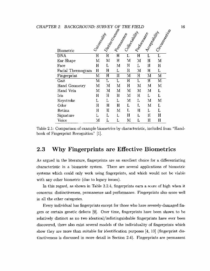
Different levels of most of these characteristics may be desirable for a particular
application. Careful consideration of what the application requires will aid in making
the best decision in designing a suitable system. Table 2.2.4 (taken from [1] with some
minor edits) describes the relative performance of several different common (and a
few uncommon) biometric types with regard to each of the characteristics described
in this section.
It is evident from Table 2.2.4 that fingerprints are an excellent choice when de
signing biometric systems. This assertion will be discussed in greater detail below.
Other reasonable choices include irises and retina.
CHAPTER 2. BACKGROUND: SURVEY OF THE FIELD 16
A $ <J> iP •# J? & £
;> & 2? & £ &
Biometric
./ O
£ £
C? £
ST
/ T C7
DNA H H H L H L L Ear Shape M M H M M H M Face H L M H L H H Facial Thermogram H H L H M H L Fingerprint M H H M H M M Gait M L L H L H M Hand Geometry M M M H M M M Hand Vein M M M M M M L Iris H H H M H L L Keystroke L L L M L M M Odor H H H L L M L Retina H H M L H L L Signature L L L H L H H Voice M L L M L H H
Table 2.1: Comparison of example biometrics by characteristic, included from "Handbook of Fingerprint Recognition" [1],
2.3 Why Fingerprints are Effective Biometrics
As argued in the literature, fingerprints are an excellent choice for a differentiating
characteristic in a biometric system. There are several applications of biometric
systems which could only work using fingerprints, and which would not be viable
with any other biometric (due to legacy issues).
In this regard, as shown in Table 2.2.4, fingerprints earn a score of high when it
concerns: distinctiveness, permanence and performance. Fingerprints also score well
in all the other categories.
Every individual has fingerprints except for those who have severely-damaged fin
gers or certain genetic defects [9]. Over time, fingerprints have been shown to be
relatively distinct as no two identical/indistinguishable fingerprints have ever been
discovered, there also exist several models of the individuality of fingerprints which
show they are more than suitable for identification purposes [4, 10] (fingerprint dis
tinctiveness is discussed in more detail in Section 2.4). Fingerprints are permanent
CHAPTER 2. BACKGROUND: SURVEY OF THE FIELD 17
unless the finger(s) have been damaged to the point that they will not heal; damaged
fingerprints may also possess sufficient information for identity differentiation.
There are numerous ways to collect fingerprints, and many modern techniques
only require that a finger be pressed against a sensor which prevents the need to
use the traditional ink-and-paper family of fingerprint collection methods, which are
often unpleasant. Many of the fingerprint-based biometric systems in use today are
extremely efficient, and can offer results in seconds (except in special cases like the
IAFIS which takes 10 minutes on average to retrieve results [8]).
One unfortunate aspect of using fingerprints is that there is a stigma associated
with their use. Because of their long history of use in law enforcement, people usually
associate having their fingerprints impressions collected with being treated as a crim
inal. A common complaint from individuals using systems which require fingerprints
being taken is that they feel like their privacy has been violated or that they are being
treated like criminals [11, 12, 13]. This taint of criminality is less evident in other
biometric systems such as retinal or iris scans which are increasingly used in airports.
Another unfortunate issue with using fingerprints in security (verification) is that
security measures built on fingerprints are relatively easily circumvented. If finger
prints from an individual can be obtained, with the proper "tools", there is nothing
stopping a person from accessing a system secured solely through fingerprints. How
ever, by combining fingerprints and some other type of verification, an acceptable
level of security can be reached [14].
There are several other acceptable choices for a biometric, as can be seen from
Table 2.2.4. Irises, ear shapes, or hand geometry would all be acceptable as biometrics,
although none of them have been as widely studied as fingerprints.
2.4 Fingerprint Distinctiveness and Validity/Ac-
curacy as a Biometric
The admissibility of fingerprint evidence in court is something that is generally ac
cepted today, although there has been some contention in the past.

CHAPTER 2. BACKGROUND: SURVEY OF THE FIELD 18
In order for fingerprints to be admissible for identification purposes in a courtroom,
the court requires that there has to be some proof of the "reliability" of fingerprints
as evidence as well as a notion of its "accuracy". The kind of "reliability" considered
in courtrooms is not equivalent to the definition of "reliability" used by the scientific
community [15]. Rather, a courtroom's definition of "reliability" is closer to the sci
entific definition of "validity" [15]. In order to ensure clarity the following definitions
of accuracy, reliability, and validity will be used in this work:
• Reliability is the repeatability and consistency of an experiment.
• Validity is a measure of how fairly an experiment tests its hypothesis.
• Accuracy is the difference between the experimental result and the "true"
accepted value. The stated uncertainty in an experimental result should always
be greater than this percentage accuracy. Accuracy is also associated with the
inherent uncertainty in a measurement.
To summarize, in order for a fingerprint-based identification scheme to be used in
court, one must demonstrate that the identification is both "valid" and "accurate"
[15]. Fingerprints have been used for identification for centuries [4]. The validity of
fingerprint-based identification is connected to the uniqueness of fingerprints. Al
though it is impossible to prove that all fingerprints are unique and distinguishable
[15], as mentioned above it can be empirically shown that it is valid for identifica
tion, since no two identical or indistinguishable fingerprints have been discovered [10].
The accuracy of fingerprint identification techniques, however, has been repeatedly
called into question in recent years [15], No study on the accuracy of the entire pro
cess of fingerprint identification has been reported, therefore, the accuracy of modern
fingerprint identification systems is unknown. Numerous studies of the accuracy of
the automated portion of fingerprint identification processes have been studied, the
portion that remains unstudied is the manual examination by expert witnesses. The
study of the accuracy of a full and applied fingerprint identification system is outside
CHAPTER 2. BACKGROUND: SURVEY OF THE FIELD 19
the scope of this thesis2.
2.4.1 Admissibility in Court
In the past, the admissibility of the match of a particular fingerprint as evidence
in court was decided by the number of minutiae which were successfully matched.
The requirement on this number was that it had to be at least between 8-12 There
were issues with this approach however, as the number of minutiae matched is not
directly correlated with the quality of the fingerprint matching phenomenon itself.
The quality of the area of the fingerprint image surrounding each minutiae is more
representative of the validity of each minutiae match, and consequently, of the fin
gerprint matching itself. If the fingerprint image is of low quality, it will also be
difficult for the human supervisor to determine with certainty whether or not the
match is correct. Fingerprint experts instead base the admissibility of the match on
several qualitative properties of the area surrounding the matched minutiae such as
smudging, inconsistencies in contrast, contaminants and other similar sources of noise
[!]•
2.5 Biology of Fingerprint Uniqueness
The pattern of ridges on the tips of our fingers defines our fingerprints. Formation
of fingerprint patterns have a genetic component, as evidenced in individuals with
genetic defects in epidermal ridge formation [9], but are strongly influenced by en
vironmental factors. Even identical twins who by definition share identical genomic
DNA sequences, possess fingerprints which bear similarity but not identity [16]. Fin
gerprints are fully formed prenatally and are retained throughout life. Although there
is some influence of genetics on overall patterning, environmental factors play a key
role in establishing the final patterns that an individual will carry throughout their
lifetime. The key characteristics of fingerprints first emerge when the fingertips begin
2In spite of this, it is fair to mention that the accuracy of an automated portion of a fingerprint identification system is discussed here.

CHAPTER 2. BACKGROUND: SURVEY OF THE FIELD 20
to form during embryonic gastrulation. It is believed that the unique microenviron-
ments both surrounding and within each digit influence the process of local epidermal
cell proliferation and migration. Ridge pattern formation is therefore the culmination
of many distinct local factors and forces which over the course of embryonic devel
opment are unique from digit to digit. Thus, the digits of each identical twin are
exposed to unique environments and therefore exhibit unique microdetails in finger
prints which allow for discrimination between them (see [1], and references therein).
The modern forensic use of fingerprints to identify individuals began in the 19th
century [17, 18] although as previously mentioned there are a number of reports
suggesting the awareness of fingerprint uniqueness many centuries previous [3, 19].
There are also many modern models of fingerprint uniqueness which can be used to
show that they are suitable for identification [10].
2.6 The Fingerprint Identification Process
All biometric systems follow a similar pattern in their construction and organization.
This is true for the phases up to and including the process by which they identify or
authenticate individuals.
The process begins with the data collection of raw biological data from the sub
jects). This includes pre-processing of the raw data (if necessary). This is followed
by the extraction of the useful features and the construction of the template. Match
ing based on the templates obtained from feature extraction is then involved. The
final tasks include the manual3 auditing of the results, and registration4.
2.6.1 Raw Data Collection
Collection of raw fingerprint data has changed significantly over time, starting from
simpler ink-based collection techniques to the use of much more convenient and less
error-prone fingerprint scanners. Although the standard techniques for fingerprint
3In most cases, identification systems are checked manually by an expert so as to ensure that no mistakes have been made, or to perform the final consolidation step.
4This phase is outside the scope of this thesis.
CHAPTER 2. BACKGROUND: SURVEY OF THE FIELD 21
collection have changed greatly, the use of older fingerprints in newer systems is a
necessity for several applied biometric systems. This is because fingerprints that were
collected using older techniques must still be used in some systems, and thus it is
important that the issues that are present in these collection techniques be taken into
consideration.
More recent collection techniques center around the concept of electronic finger
print scanners. These scanners use a wide variety of sensors, but all of them sub
sequently reduce the scanned fingerprint to an image of some kind. The primary
purpose of fingerprint scanners is to collect fingerprints. However, there are sev
eral electronic fingerprint scanners that include extra hardware which is capable of
performing different processing tasks up to and including matching [1].
Important Fingerprint Scanner Characteristics
In order to regulate the quality of fingerprint images produced by fingerprint scanners
and other fingerprint collection techniques, the FBI has set several restrictions on the
images produced by a fingerprint scanner. Only a scanner possessing these properties
can be used in their systems; and they in turn should have stringent requirements
with respect to geometric accuracy, fingerprint gray range, fingerprint artifacts and
anomalies, and fingerprint sharpness and detail rendition.
A summary of the requirements placed on the 500DPI fingerprint images [20] is
given below:
• Geometric Accuracy: The difference, A, between the actual value and the
measured value of distance between the test set of scanning material should not
exceed:
A < 0.0007, for 0.00 < X < 0.07
A < 0.01X, for 0.07 < X < 1.50,
where:
A = \ Y - X \ ,

CHAPTER 2. BACKGROUND: SURVEY OF THE FIELD 22
X = actual target distance,
Y = measured image distance,
A, X, Y are in inches.
• Fingerprint Gray Range: For the majority of the produced images, there
should be at least 200 gray-levels (before the conversion to a digital image).
• Fingerprint Artifacts and Anomalies: Artifacts or anomalies produced by
the scanner must not have a significant adverse affect on the corresponding
matching systems.
• Fingerprint Sharpness and Detail Rendition: The sharpness and detail
of the fingerprint images should be high enough to support conclusive finger
print comparisons, fingerprint classification, automatic feature detection, and
the overall Integrated Automated Fingerprint Identification System.
Off-line Fingerprint Sensing
Off-line fingerprint sensing includes the "ink-technique" as well as the collection of
latent fingerprints. The most commonly used technique for fingerprint collection in
law enforcement is known as the "ink-technique" [21, 22]. This technique is being
replaced by electronic scanners over time, but it is still used today [1]. As a result,
automated fingerprint identification systems must be able to handle both fingerprints
collected using the "ink-technique" style and those collected by electronic scanners.
We summarize below the procedures for collecting fingerprints via the "ink-technique"
[8]:
1. The subject is to wash his/her hands with soap and water or rubbing alcohol;
2. The height for recording fingerprints is approximately 39 inches (99.06cm) from
the floor.
3. The subject must be instructed to look away from the fingerprint device, and
not to assist in the process.
CHAPTER 2. BACKGROUND: SURVEY OF THE FIELD 23
4. The fingerprint pattern areas must be covered evenly with ink.
5. Each finger on the collection paper must be rolled from "nail-to-nail".
6. The paper must later be scanned and stored in a database.
Ink-based techniques are susceptible to error, and require great skill to perform
properly and without incident [8]. There are obvious advantages to developing fin
gerprint collection techniques which do not require training as extensive or as specific
as that required for ink-based techniques.
In addition to fingerprint collection in a controlled environment, collection tech
niques of latent fingerprints are extremely important, and is a subject of much re
search. As there axe a wide variety of possible surfaces where the fingerprints could
be located, there are also a wide variety of techniques for latent fingerprint extraction
from various substrates.
Latent fingerprints are the result of oil and moisture on the fingertips, which, in
turn, leave residue on various objects, which can be analyzed to get an impression
of a fingerprint. These fingerprint impressions are of notoriously low quality, and
as a result often require clever techniques to enhance their impression. Common
techniques for latent fingerprint collection include dusting, ninhydrin spraying, iodine
fuming, and silver nitrate fuming [21, 22].
On-line Fingerprint Sensing
On-line fingerprint sensing primarily consists of fingerprint scanners. These scanners,
usually, follow a pattern in their construction. All fingerprint scanners have a sensor
for collecting the analog data, and a method of converting this data into digital
information (see Figure 2.1).
Fingerprint scanners today most often operate using the principle of Frustrated
Total Internal Reflection (FTIR). FTIR is also one of the oldest techniques for on-line
fingerprint collection [23].
A glass prism is the surface touched by the finger. As a result of this, diffused light
is emitted from one side of the prism and reflected or absorbed by the fingerprint's
CHAPTER 2. BACKGROUND: SURVEY OF THE FIELD 24
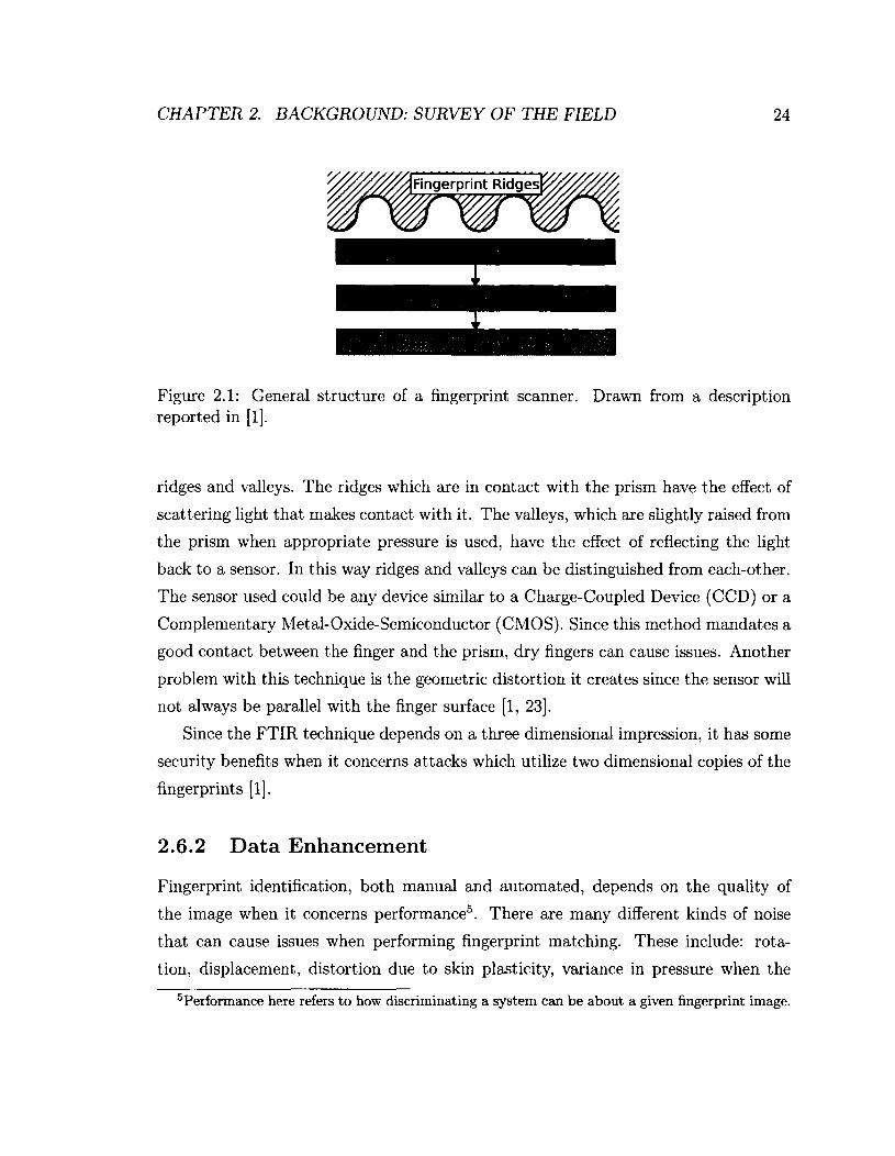
Fingerprint Ridges^
Figure 2.1: General structure of a fingerprint scanner. Drawn from a description reported in [1],
ridges and valleys. The ridges which are in contact with the prism have the effect of
scattering light that makes contact with it. The valleys, which are slightly raised from
the prism when appropriate pressure is used, have the effect of reflecting the light
back to a sensor. In this way ridges and valleys can be distinguished from each-other.
The sensor used could be any device similar to a Charge-Coupled Device (CCD) or a
Complementary Metal-Oxide-Semiconductor (CMOS). Since this method mandates a
good contact between the finger and the prism, dry fingers can cause issues. Another
problem with this technique is the geometric distortion it creates since the sensor will
not always be parallel with the finger surface [1, 23].
Since the FTIR technique depends on a three dimensional impression, it has some
security benefits when it concerns attacks which utilize two dimensional copies of the
fingerprints [1].
2.6.2 Data Enhancement
Fingerprint identification, both manual and automated, depends on the quality of
the image when it concerns performance5. There are many different kinds of noise
that can cause issues when performing fingerprint matching. These include: rota
tion, displacement, distortion due to skin plasticity, variance in pressure when the
Performance here refers to how discriminating a system can be about a given fingerprint image.
CHAPTER 2. BACKGROUND: SURVEY OF THE FIELD 25
print is taken, use of older fingerprint images, and differences in fingerprint collection
techniques.
There are a number of pre-processing techniques reported in the literature that
can be used to improve the relative quality of the raw fingerprint data so that the
relevant important features axe more easily extracted. These types of noise could
include pixel-damage, inconsistent contrast, discontinuities in ridges, and the lack of
depth in the gradient of the intensity between the ridges and valleys [4],
The different techniques that are often used to enhance a fingerprint image before
it is used by a matching algorithm include Gaussian blurring, contrast adjustment,
and the binarization of the image (using histogram analysis and thresholding). These
are explained in more detail in Chapter 3.
2.6.3 Feature Extraction and Template Construction
Feature extraction is the process of extracting useful features for identification and/or
authentication from the biometric. This phase is tied to the process of image enhance
ment, and it is difficult determine where the image enhancement process ceases and
the feature extraction begins [1]. The steps involved in feature extraction, especially
when it concerns minutiae, almost always involves all or a subset of the following as
outlined in [1]:
• Orientation estimation.
• Frequency estimation.
• Segmentation of the image into similar regions.
• Ridge detection and thinning.
• Minutia detection.
Orientation estimation, frequency estimation, ridge detection and thinning, and
image segmentation are also used in many types of fingerprint image enhancement
modules. This is what makes the distinction between the two stages difficult [24, 25].
CHAPTER 2. BACKGROUND: SURVEY OF THE FIELD 26
The feature most commonly extracted from fingerprints for analysis are the so-
called minutiae or singular points (see Figure 2.3). The exact definition of the term
"minutia" differs across the literature but it is most often used to refer to several
different types of ridge features in addition to a set of associated metrics. There are
three types of minutiae typically extracted by minutia-extraction algorithms. These
minutiae are known as ridge bifurcations, ridge endings and ridge islands or dots.
Minutiae are usually represented using their Cartesian coordinates, along with some
additional relevant data, for example, a quality score, the angle of the most closely-
associated ridge, and the minutia type6. Minutia are typically stored as a 3-tuple,
(.x,y,6), where x and y are the Cartesian coordinates, and 6 is the angle of the most
closely-associated ridge to the given minutia with the horizontal axis.
Most methods of minutia-extraction follow a similar pattern involving an orienta
tion estimation, segmentation of the fingerprint image, ridge detection and thinning,
and finally, the minutia detection itself.
Orientation Estimation
This phase of the minutia-extraction process is used later to determine the 6 value
of each minutia and is used in several different minutia-extraction algorithms. The
fingerprint image is typically separated into small regions and the gradient is analyzed
to estimate the average direction of the ridges contained within that particular section.
In order to make the estimate as accurate as possible the regions can be reduced in
size [26].
A simple method for accomplishing the analysis of the gradient in each region is by
sampling a set of pixels and determining the gradient at each pixel's location. Once
the gradient has been determined, the direction of the ridges should be perpendicular
to the angle of the gradient [1].
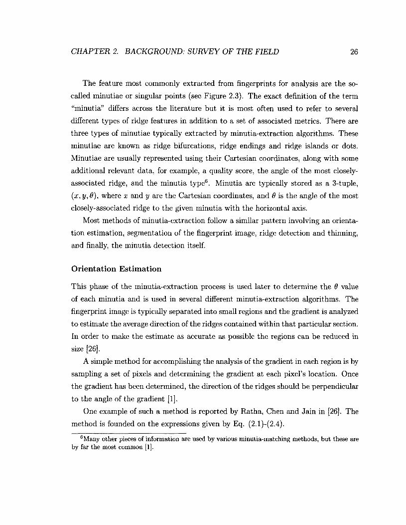
One example of such a method is reported by Ratha, Chen and Jain in [26]. The
method is founded on the expressions given by Eq. (2.1)-(2.4).
6Many other pieces of information are used by various minutia-matching methods, but these are by far the most common [1].
CHAPTER 2. BACKGROUND: SURVEY OF THE FIELD 27
1 2 G dij = 90° + - arctan ——, (2.1)
8 8
(*xy — ̂ ̂"] Vx(xj + /i, + fc) • Vy(xj + h,yj -t- A;), (2.2) h=—Sk=-8
8 8
£*XX ^ ^ + /i, Uj + k) , (2.3) h=—S fc=—8
8 8 8 8
^vv ~ ^ ^ ' VJ/(xj + /i, + A:) . (2.4) h=—8fc=—8
Frequency Estimation
Frequency estimation deals with the task of determining the approximate frequency of
the ridges in a certain region. Several different techniques make use of this information
including the Gabor filtering process described in Section 2.6.2.
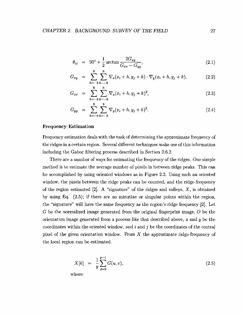
There are a number of ways for estimating the frequency of the ridges. One simple
method is to estimate the average number of pixels in between ridge peaks. This can
be accomplished by using oriented windows as in Figure 2.2. Using such an oriented
window, the pixels between the ridge peaks can be counted, and the ridge-frequency
of the region estimated [2]. A "signature" of the ridges and valleys, X, is obtained
by using Eq. (2.5); if there are no minutiae or singular points within the region,
the "signature" will have the same frequency as the region's ridge frequency [2]. Let
G be the normalized image generated from the original fingerprint image, O be the
orientation image generated from a process like that described above, x and y be the
coordinates within the oriented window, and i and j be the coordinates of the central
pixel of the given orientation window. From X the approximate ridge-frequency of
the local region can be estimated.
y-i (2.5)
where:

CHAPTER 2. BACKGROUND: SURVEY OF THE FIELD 28
Figure 2.2: Illustration of an orientation window on a group of ridges with similar 6 values. Diagram similar to that in [2].
Segmentation of the Image
Most fingerprint images will have areas which are not related to the fingerprint it
self, and instead, consist of blank space containing only noise. The noise could be
accumulated from several different sources: from dust, grease or from other contam
inants that have been left behind on the fingerprint scanner from previous subjects.
Besides these, other areas can be damaged or be highly distorted portions of the fin
gerprint impression itself, which are rendered unusably noisy as a result of smudging
or improper pressure. In order to prevent the collection of erroneous minutiae, it is
obviously desirable to mark off these sections which are too noisy or which are not
part of the fingerprint so that they may be ignored. The areas which do not contain
any useful information are generally referred to as the "background", and the areas
which contain useful fingerprint ridges are referred to as the "foreground" [2].
It is difficult to separate the foreground from the background by using only pixel
intensity and thresholding, since fingerprints themselves are striated patterns [27].
Because of noise, it may also be difficult to distinguish the areas which do not contain
fingerprint ridges from the foreground.
u
v
(2.6)
(2.7)
CHAPTER 2. BACKGROUND: SURVEY OF THE FIELD 29
One successful technique for separating the foreground from the background was
presented by Mehtre et al. [28]. This technique is based on achieving a segmentation
of the fingerprint image using the ridge orientations. By mapping locations based
on their ridge orientations, and by also using the histogram of the orientations, the
foreground can be distinguished by analyzing the peaks in the histograms.
Segmentation can also be achieved through another technique proposed in [26].
This method is able to segment the fingerprint image based on the so-called "areas of
interest". The algorithm is capable of determining which regions contain high noise
and/or which areas lack fingerprint ridges7 and to thereafter mask them. This is
accomplished by computing the variance in gray levels in the direction perpendicular
to the orientation field in each region or block that is visited. The "areas of interest"
are then the regions or blocks with the highest variance, where this conclusion is based
on the assumption that in any "areas of interest", there will be a great variance in
the pixel intensity in the direction perpendicular to the dominant ridge orientation.
Ridge Detection/Thinning and Minutia Detection
The final step in the minutia-extraction process is to perform the extraction itself.
Several different types of minutiae can be found in fingerprints, and the three most
common types are illustrated in Figure 2.3.
A common technique for minutia-extraction is the reduction of the remaining
fingerprint image to a skeletal representation, which, in turn, is achieved by finding
the peaks of the gradients between the ridges, and by marking them as the pixels
which represent the ridge-peaks [29]. By keeping only those pixels which represent
ridge-peaks, one can obtain an image which contains thinned-out representations of
these ridges. Once there are only single pixel wide representations of the ridges, simple
and straightforward minutia detection techniques can be used on the remaining image
skeleton. Although, at this stage, minutia detection can be performed, we believe that
filtering should be performed so as to remove any of the spurious ridges created from
the process of reducing the image to its skeleton [2]. Finally, once the image has been
appropriately filtered, the minutia detection can be performed.
7These regions are the empty regions or regions with only smudges and blurred areas.
CHAPTER 2. BACKGROUND: SURVEY OF THE FIELD 30
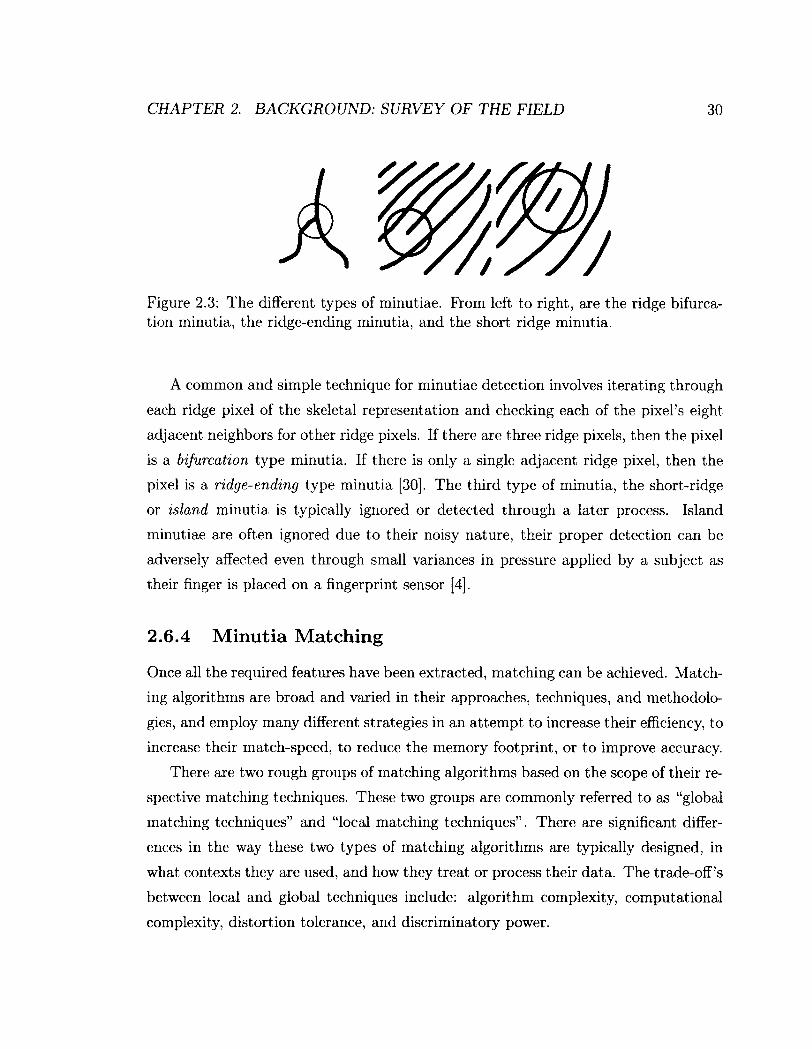
Figure 2.3: The different types of minutiae. Prom left to right, are the ridge bifurcation minutia, the ridge-ending minutia, and the short ridge minutia.
A common and simple technique for minutiae detection involves iterating through
each ridge pixel of the skeletal representation and checking each of the pixel's eight
adjacent neighbors for other ridge pixels. If there are three ridge pixels, then the pixel
is a bifurcation type minutia. If there is only a single adjacent ridge pixel, then the
pixel is a ridge-ending type minutia [30]. The third type of minutia, the short-ridge
or island minutia is typically ignored or detected through a later process. Island
minutiae are often ignored due to their noisy nature, their proper detection can be
adversely affected even through small variances in pressure applied by a subject as
their finger is placed on a fingerprint sensor [4],
2.6.4 Minutia Matching
Once all the required features have been extracted, matching can be achieved. Match
ing algorithms are broad and varied in their approaches, techniques, and methodolo
gies, and employ many different strategies in an attempt to increase their efficiency, to
increase their match-speed, to reduce the memory footprint, or to improve accuracy.
There are two rough groups of matching algorithms based on the scope of their re
spective matching techniques. These two groups are commonly referred to as "global
matching techniques" and "local matching techniques". There are significant differ
ences in the way these two types of matching algorithms are typically designed, in
what contexts they are used, and how they treat or process their data. The trade-off's
between local and global techniques include: algorithm complexity, computational
complexity, distortion tolerance, and discriminatory power.

CHAPTER 2. BACKGROUND: SURVEY OF THE FIELD 31
Figure 2.4: The minutiae on this fingerprint have been highlighted with red squares, the blue line indicates the direction of the most closely associated ridge, this is known as the minutia's 0 value.

CHAPTER 2. BACKGROUND: SURVEY OF THE FIELD 32
Global Schemes
Global techniques favor viewing the fingerprint as a whole by taking into account
all the global-spatial relationships between fingerprint features. Because the global-
spatial relationships hold a great deal of valuable distinctive information, it is clear
that global techniques are capable of greater discrimination between fingerprints [4].
A disadvantage of such global techniques, however, is that the same features that lead
to the global techniques providing improved accuracy and discrimination capabilities,
also give them a greater sensitivity to noise. Global spatial features and structures
are more affected by noise than the smaller and more local structures and features
which are used in locally-oriented algorithms [1].
Many global algorithms go through an extensive and detailed alignment process
in order to align the minutiae as closely as possible. This is because these algorithms
are often rotation dependent.
Local Schemes
Local techniques favor viewing the fingerprint as a group of localized structures or
clusters of structures. Local techniques, typically, differ in the way in which they en
code the information contained within local minutiae into structures. Local matching
works on the principle of testing for the presence of these different localized structures.
Although the structures themselves may not be unique to a particular fingerprint, a
particular combination of those structures may be. As a consequence of the nature
of local matching, more fingerprint images are usually required to match one physical
fingerprint to another. Another technique for ensuring accuracy and the elimination
of false positives (which are common in local matches) is a consolidation step [1, 25].
As a result of discarding the global-spatial relationships in favor of localized ones,
local matching algorithms are less sensitive to various types of noise (e.g., displace
ment, and distortion due to skin plasticity). Another result of eschewing global-spatial
relationships is the potential for creating rotationally independent algorithms. Indeed,
several of these algorithms have been reported in the literature [1].
CHAPTER 2. BACKGROUND: SURVEY OF THE FIELD 33
2.7 Non-Minutia-based Matching Techniques
In addition to minutiae, other features present in fingerprints have been used for
identification and authentication purposes. The different features of fingerprints have
been roughly divided into three levels [31]. The first level of features encompass the
ridge flow and the pattern shape of the fingerprint. The second level contains the
minutiae. The third level includes all the remaining attributes of the ridges (e.g.,
width, shape, edge contour, pores, and scars).
Minutiae have been studied in great detail in the literature and have been the
cornerstone of research in fingerprint-based identification and authentication [4], but
the third level features have been less popular as a subject of study due to the stringent
requirements on the level of detail required in the image (usually greater than 1,000
DPI) [31]. In spite of this, less popular algorithms, which make use of level three
features, do exist in the literature.
Pores have gained some interest in recent years as being features with which one
can discriminate fingerprints. The purpose of the pores on the finger are primarily to
excrete oil and sweat. They are present only on ridges and appear either open and
closed. Pores will not always be detected by scanners because of the varying level
of pressure applied by the subject. This results in an inconsistent number of pores
between fingerprint scans, which, obviously, poses a problem for matching using pores
[31].
As a feature for fingerprint identification they can be used to improve the discrim
inatory power of a fingerprint system. However, as with other level three features
they require a higher resolution fingerprint image than is standard8 in order to be
properly extracted.
One of the early techniques which used pores and other level three features for
identification/authentication was presented in [31]. Pore extraction was performed
by using a Gabor filter to extract only the ridges and to fill in all the pores. Once
extraction has been completed the Gabor-filtered image was added to the original to
allow for the use of a band pass filter to collect the high negative frequency response
8The most common format for fingerprint images is 500 DPI.
CHAPTER 2. BACKGROUND: SURVEY OF THE FIELD 34
of the change of the intensity of the pores. The frequency response is obtained using a
Mexican Hat wavelet transform. Once the pores are extracted, matching proceeds in
much the same manner as with minutia matching but with extra measures to handle
the unique characteristics of pores [31].
2.7.1 Refining Results
Biometric identification systems like those used by the FBI and RCMP have very
large databases [1, 8] and because of the nature of identification, "1-to-N" matches
are required. Each fingerprint matching process is inherently independent, and it is
obvious that the identification process's computation time grows linearly with the
size of the database.
In order to compensate for the massive amount of computation required for the
equally massive databases of the FBI and RCMP, there are several techniques which
can be exploited to reduce the amount of computation required. In addition, most of
the steps in fingerprint matching can be performed in advance of a query template.
As a result of this independence, it is obvious that the fingerprint matching process is
trivially parallelizable. A trade-off between the overall system cost and its matching
speed is a truism, permitting nearly arbitrary speed without the need to sacrifice
accuracy9.
Many systems use a hierarchical approach to matching in order to reduce the
amount of computation required. Using level one features, such as fingerprint patterns
(e.g., loop, and whorl), allows for the quick elimination of highly dissimilar fingerprints
to that of the template, which can greatly reduce the amount of processing necessary
[4].
2.8 Chapter Summary
In this chapter we have discussed a variety of topics related to fingerprint matching
in order to give context to the remaining chapters of this thesis. We have discussed:
9This, of course, implies "infinite" resources too!

CHAPTER 2. BACKGROUND: SURVEY OF THE FIELD 35
• Generic biometric systems and their relationship to fingerprint matching sys
tems.
• Important points of consideration when designing a biometric system.
• Why fingerprints are an appropriate choice for biometric systems.
• The validity of using fingerprints for identification.
• The biological aspects of fingerprint uniqueness.
• The Fingerprint matching process.
Knowledge of these areas is essential for building the necessary context with which
to understand and appreciate the remaining chapters.
Chapter 3
Image Processing Aspects
Image processing is fundamental to the fingerprint matching process, and is discussed
briefly in Chapter 2 (Section 2.6.2).
The ultimate goal of image processing, when it concerns fingerprint identifica
tion/verification, is the improvement of the overall quality of the input fingerprint
images. Ideally, an image processing phase would be able to take a very low quality
fingerprint and output a high quality one. The damage/noise that is typically present
in fingerprint images includes the following types [1]:
• Breaks in the continuity of the ridges.
• Shallow gradient between the ridges (caused by smudging or otherwise).
• Damage to the finger itself through cuts, creases, burns, and bruises.
• Damage or noise added through the measurement equipment itself.
Some of these are obvious to the human eye, and unsurprisingly, fingerprint experts
are able to repair "recoverable regions" of fingerprints by invoking fingerprint image-
preparation programs [1]. This has been used to support the argument that these
"recoverable regions" should be detectable and repairable by a machine [1]. Areas
which cannot be repaired can be removed or "masked" using segmentation techniques
as detailed in 2 (Section 2.6.3).
36

CHAPTER 3. IMAGE PROCESSING ASPECTS 37
The methods used to cope with such damage/noise include several different fil
tering techniques. Some of the more common techniques for fingerprint image en
hancement will be discussed in Section 3.2 including Gaussian blurring, contrast
adjustment, Gabor-based filtering, and fingerprint image binarization. Beyond the
techniques covered in Section 3.2, many schemes for image enhancement exist in the
literature, which can be used in an attempt to improve the quality of the fingerprint
images themselves.
Due to the greatly varying nature in which minutia matching algorithms operate,
image enhancement techniques which work well for a given matching algorithm may
not provide the same level of enhancement, for other matching algorithms. Rather,
they may even reduce the effectiveness of some matching techniques due to the loss of
certain features [1]. This will become increasingly pronounced as the use of features
other than minutiae become widespread.
In the following chapter, we will discuss the image processing techniques imple
mented for use in the developed system, all of which were for adding artificial noise.
We will also discuss methods of image enhancement commonly used in fingerprint
matching systems. Subsequently we will briefly discuss the additional tools used in
the developed system.
3.1 Adding Artificial Noise
For the purposes of testing the resistance to noise of the implemented algorithms,
three separate algorithms for adding noise were developed: an algorithm providing
two-dimensional convolution with an arbitrary square kernel, an algorithm provid
ing Gaussian additive noise, and finally, an algorithm providing randomized pixel-
damage. Each of these noise types are displayed in Figure 3.1. Any of these tech
niques can be used to apply noise before executing a matching algorithm to test for
its sensitivity to noise.
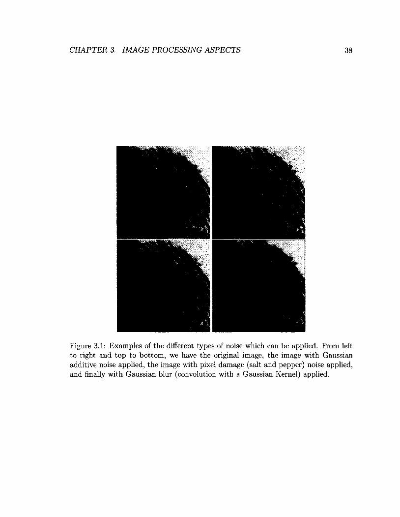
CHAPTER 3. IMAGE PROCESSING ASPECTS 38
Figure 3.1: Examples of the different types of noise which can be applied. From left to right and top to bottom, we have the original image, the image with Gaussian additive noise applied, the image with pixel damage (salt and pepper) noise applied, and finally with Gaussian blur (convolution with a Gaussian Kernel) applied.
CHAPTER 3. IMAGE PROCESSING ASPECTS 39
3.1.1 Convolution with Arbitrary Kernels
Convolution is a powerful technique in image processing/manipulation. With the aid
of a diverse set of kernels, convolution can provide a variety of different effects on the
target image.
The convolution technique is summarized in Algorithm 1. This is an overly-
simplified version of the actual algorithm used which, while optimized, is quite com
plex for illustrative purposes. The algorithm uses the input array of the raw image
data A, and the input array of the kernel data JC, and processes them to perform the
convolution.
Algorithm 1 Simplified Two Dimensional Convolution Algorithm Input 1: A: The input image. Input 2: JC: The kernel. Output: A: The convolved image. for m <— 0; m < rows; 4- + m do
for n <— 0; n < columns; + + n do
end for end for return A
An arbitrary kernel can be chosen for to be used in the convolution algorithm. If no
kernel is provided, the default is a 5 x 5 Gaussian kernel. Performing the convolution
with this kernel is equivalent to applying Gaussian blur to the target image. This
operation can either improve or reduce the quality of the image, this is dependent on
the state of the input image.
3.1.2 Pixel-Damage-Based Noise
Pixel-damage1 is a type of noise which is usually added at the raw input stage. If
the sensor array portion of the fingerprint scanner is damaged, it is possible for
lrThis type of noise is commonly referred to as "salt-and-pepper noise".
OO OO

CHAPTER 3. IMAGE PROCESSING ASPECTS 40
certain pixels to be "knocked-out" or inverted. The algorithm developed is intended
to simulate this type of noise, where pixels will get "flipped" with a certain probability.
Pixel-damage is performed by using Algorithm 2, where A is the one dimensional
array of the raw fingerprint-image data, |.4| is the size of A, and p is the probability
of causing pixel damage to each individual pixel. The pixel damage itself is caused
by setting a pixel Ai to 255 — A\ thus "flipping" its value.
Algorithm 2 Pixel Damage Algorithm Input: A: The input image. Output: A: The noisy image, garbled with pixel-based noise. for i 4- 0; i < |*4|; i 4- i + 1 do
r 4— rand() if r < p then
Ai 4— 255 — At end if
end for return A
3.1.3 Additive Gaussian Noise
In order to simulate additive noise due to sensor devices, another algorithm was
included which garbles the target image using Gaussian noise. Additive Gaussian
noise simulates a noisy sensor adding "white-noise" to the target image.
Gaussian additive noise was generated by adding a normally-distributed random
number to each of the pixels. The random number was generated using a Box Muller
Transform (BMT) random number generator (Algorithm 3), where a is the desired
standard deviation and n is the desired mean. Algorithm 4 describes how the numbers
generated by Algorithm 3 are added to the image data, A.
The additive Gaussian noise will cause the gradients between the ridges to become
rough and may cause the minutia-extraction algorithm to produce incorrect results.
This will, in turn, give the minutia matching algorithm spurious minutiae or prevent
it from finding some minutiae.

CHAPTER 3. IMAGE PROCESSING ASPECTS 41
Algorithm 3 Box Muller Random Number Generator Input 1: fi: the desired standard deviation of the random numbers generated. Input 2: a: the desired mean of the random numbers generated. Input 3: Although not a direct input initialization of the seed of the chosen random number generator may be required. This is dependent on the implementation language/runtime and random number generator selected. Output: Random Normally distributed number. static iii A— 0.0 static m2-saved <— false if not u2 -saved then
repeat x i— 2.0 • rand() — 1 y <— 2.0 • randQ — 1 r •f- x2 + y2
until r ^ 0.0 and r < 1 . 0
Ul x.
U2-saved <— true return U\ • a + n
else U2 -saved <— false return m2 • cr + ̂
end if
Algorithm 4 Additive Gaussian Noise Input: A: The input image. Output: A: The noisy output image, for i <r- 0; i < |-4|; + + i do
r <— Box_Muller(/i, a) if (temp 4- r + Ai) > 255 then
temp <- 255 else if temp < 0 then
temp <— 0 end if Ai 4— temp
end for return A
CHAPTER 3. IMAGE PROCESSING ASPECTS 42
3.2 Image Enhancement Methods
As previously mentioned there are a number of different techniques for improving
the quality of fingerprint images (with respect to fingerprint recognition). The most
common techniques are covered in this section.
3.2.1 Gaussian Blur
Gaussian blurring is a common technique used by many different fingerprint matching
algorithms since it effectively reduces Gaussian noise (also known as "white noise"),
which could have been added by virtue of the tools used to obtain the raw fingerprint
data.
Gaussian blur is performed fairly simply by performing a 2-dimensional convolu
tion with a Gaussian kernel given by Eq. (3.1).
<?(,,„)_ (3.1)
This process has the effect of reducing the amount of "white noise" or "Gaussian
noise" in the image.
3.2.2 Contrast Adjustment and Normalization
There are a number of different techniques for contrast adjustment and intensity
normalization. One of the more common techniques used is a pixel-wise normalization
using the actual mean and variance, n and a2, respectively, as well as the target
mean and variance, Hq and <7q, respectively. Each input pixel I(i,j) is converted to
its corresponding output pixel G(i,j) using Eq. (3.2) [2].
G ( i , j ) -M)2
a2
-M)2
+ i f W J ) > n ( 3 2 )

CHAPTER 3. IMAGE PROCESSING ASPECTS 43
3.2.3 Gabor-Filtering-Based Fingerprint Image Enhancement
A technique presented by Hong, Wan, and Jain [2] for recovering high noise areas
on fingerprint images uses an adaptive Gabor filtering scheme to significantly reduce
noise and to repair damage like broken ridges and disparity in contrast.
The technique has 5 stages that are similar to those used by other image enhance
ment methods:
1. Contrast Normalization
2. Local Orientation Estimation
3. Local Frequency Estimation
4. Region Mask Estimation
5. Filtering
Steps 4 and 5 are where this technique deviates from most other fingerprint image
enhancement methods. Step 4 creates a region mask by splitting the image into
classified regions which are either "recoverable", and which can be reconstructed or
filtered of noise, or "unrecoverable" in which case the noise or damage is too great
and the region should be ignored. Step 5 uses a bank of Gabor filters tuned to the
local ridge orientation and ridge frequency. By using the information provided by
the frequency and orientation of parallel ridges, a bandpass filter can be configured
to remove the unwanted noise in small local regions, and subsequently the entire
fingerprint image.
In order to apply a Gabor filter, given in Eq. (3.3), to the fingerprint image, three
parameters are required:
1. The frequency of the ridges in the given region, /.
2. The orientation of the ridges in the given region, 4>
3. The standard deviations of the Gaussian envelope, Sx and Sy.

CHAPTER 3. IMAGE PROCESSING ASPECTS 44
h ( x , y : ( f ) , f ) = e x p j-i ^ J cos(2irfx4>), (3.3)
where : = x cos (j> + y sin (j), (3.4)
y# = — x sin <f> + y cos (j). (3.5)
The frequency and orientation are obtained based on the current region being
filtered. The selection of the values of 8X and 5y involves a trade-off. The large the
values, the more robust the filter will be to noise; however the more likely is that
the filter will create spurious ridges and valleys [2]. Similarly, smaller values of these
parameters will create less spurious ridges, but be less effective in removing noise [2].
The enhanced image E is obtained using Eq. (3.6):
255 if R { i , j ) = 0,
jTjfa j\ = J wg/2 *"?/2
Y Y H u t v : 0 ( i , j ) , F ( i , j ) ) G ( i - u , j - v ) otherwise, U= — 1Vg/2 V=~Wg/2
(3.6)
where G is the normalized fingerprint image, O is the orientation image, F is the
frequency image, R is the recoverable mask obtained from step 4, and wg is the size
of the Gabor filter.
3.3 Additional Image Processing Tools Used
In the development of our thesis, we used several tools produced by the National
Institute of Standards and Technology (NIST) for image processing. These tools are
all part of the the NIST Biometric Image Software (NBIS) toolkit.
A Wavelet/Scalar Quantization (WSQ) compression algorithm, and the corre
sponding decompression algorithm ("cwsq" and "dwsq" respectively) were used as
part of the fingerprint identification system.
In order to convert images between different formats which are more widespread
(formats including JPEG and PNG), the Python Image Library (PIL) was used.

CHAPTER 3. IMAGE PROCESSING ASPECTS 45
These image manipulation tools were utilized to draw minutiae on fingerprint images,
and also to convert raw and WSQ format images into PNG for use with existing image
viewers.
3.4 Chapter Summary
In this chapter we have covered one of the most fundamental portions of the finger
print matching process, image processing. Specifically we have discussed the noise
inherent in the fingerprint matching problem, several methods of garbling fingerprint
images, several commonly used fingerprint image enhancement methods, and the im
age processing tools used throughout the study.

Chapter 4
File Format Considerations
Fingerprint image libraries exist which, without proper measures, would create im
practical storage requirements. The FBI's fingerprint database is upwards of 66 mil
lion templates, many with full ten-print cards1 and even multiple sets of prints [8].
The following chapter describes the measures which have been taken to solve this
particular problem: the creation of the WSQ image format for fingerprint images in
identification systems. In addition, this chapter will touch on the different file formats
which are used in the developed system.
4.1 Importance of Compression
Fingerprint data is most often stored as images. This not only preserves as much
information about the fingerprint as possible, it also permits the use of new feature
extraction and fingerprint matching techniques with legacy fingerprints, potentially
producing new and interesting results.
The disadvantage of storing fingerprints as images (instead of storing files as lists
of extracted features) is that images are quite large in comparison to the feature
information alone. Indeed, much of the fingerprint image is noise when it concerns
fingerprint matching algorithms [2]. For small databases of fingerprints this is not
an issue. But for large organizations like the FBI, the cost of maintaining loss-less
1For example ten-prints, which would include each of the subject's 10 fingerprints.
46

CHAPTER 4. FILE FORMAT CONSIDERATIONS 47
images is too prohibitive when the size of their database is taken into consideration
(upwards of 66 million templates) [8].
In order to solve this storage problem, it is obviously desirable to compress the
fingerprint image data as much as possible while still retaining all the useful feature
information.
4.2 Problems with Pre-Existing Image Compres
sion Techniques
A number of techniques for image compression are in use today. Both loss-less and
lossy compression techniques for the commonly used PNG, TIFF and JPEG formats
exist. While many of these techniques provide adequate compression ratios for finger
print images, it is often the case that a substantial portion of the useful information
contained within these fingerprints is lost [4].
Loss-less compression techniques provide a compression factor of approximately 2
on gray-scale images which was considered inadequate by the FBI [1], Other popular
compression techniques, when tuned to the FBI's compression requirements of 0.75
bits per pixel, remove too much information and produced interfering "block-effects"
which are visible in Figure 4.1 [1]. The effect of this type of distortion on minutia
collection is obviously detrimental. The "block" noise can "shear" ridges which, in
combination with the ridge thinning process, may cause spurious ridge-ending type
minutiae. The extent to which spurious minutiae are produced is dependent on the
severity of the "block" noise and the method used to thin the fingerprint ridges [1].
4.3 Wavelet Scalar Quantization Compression
In response to the lack of a suitable compression algorithm, particularly when the
lack of storage became a crucial issue for the FBI, research into alternatives became
necessary. The compression standard produced as a product of the research from
Hopper, Preston, Bradley and Brislawn, and the FBI, is known as the Wavelet/Scalar

CHAPTER 4. FILE FORMAT CONSIDERATIONS 48
Quantization (WSQ) compression scheme [1, 32, 33].
WSQ compression is based on an adaptive scalar quantization approach [33]. It
achieves the compression level required by the FBI standards and causes only small
loss in feature data.
The following steps summarize the WSQ compression algorithm:
1. A 2-dimensional discrete wavelet transform is applied to the fingerprint in order
to decompose it into 64 different spatial frequency bands.
2. The output of the transform is quantized into discrete values, which is one phase
of the actual compression portion of the algorithm. This is also the step that
cannot truly be reversed and leads to the data loss.
3. In order to produce the final compressed image, Huffman-coding is used on the
output of the quantization step.
WSQ compression is an excellent technique for fingerprint image compression. It
provides a compression ratio of up to 15 : 1 with an associated acceptable data loss
[1, 32, 33],
Figure 4.1 exemplifies the "block-effects" on the ridges which result from other
lossy compression techniques. In the JPEG compressed image, not only are the
ridges no longer smooth, but features like pores have been completely eliminated
from the JPEG compressed image. The "block-effects" that are present on the ridges
create issues for minutia detection as a result of the harsh gradient changes from
"block-to-block". Additional details like small outcroppings on the ridges are often
eliminated or rendered indistinguishable as a result of block-noise. In contrast, the
WSQ compressed image does not have any "block-effects" and its ridges are much
smoother. Pores are visible but still may be more difficult to extract from the WSQ
compressed image [1]. Each of the features which have been degraded or eliminated
by the JPEG compression technique axe all applicable in court [1].
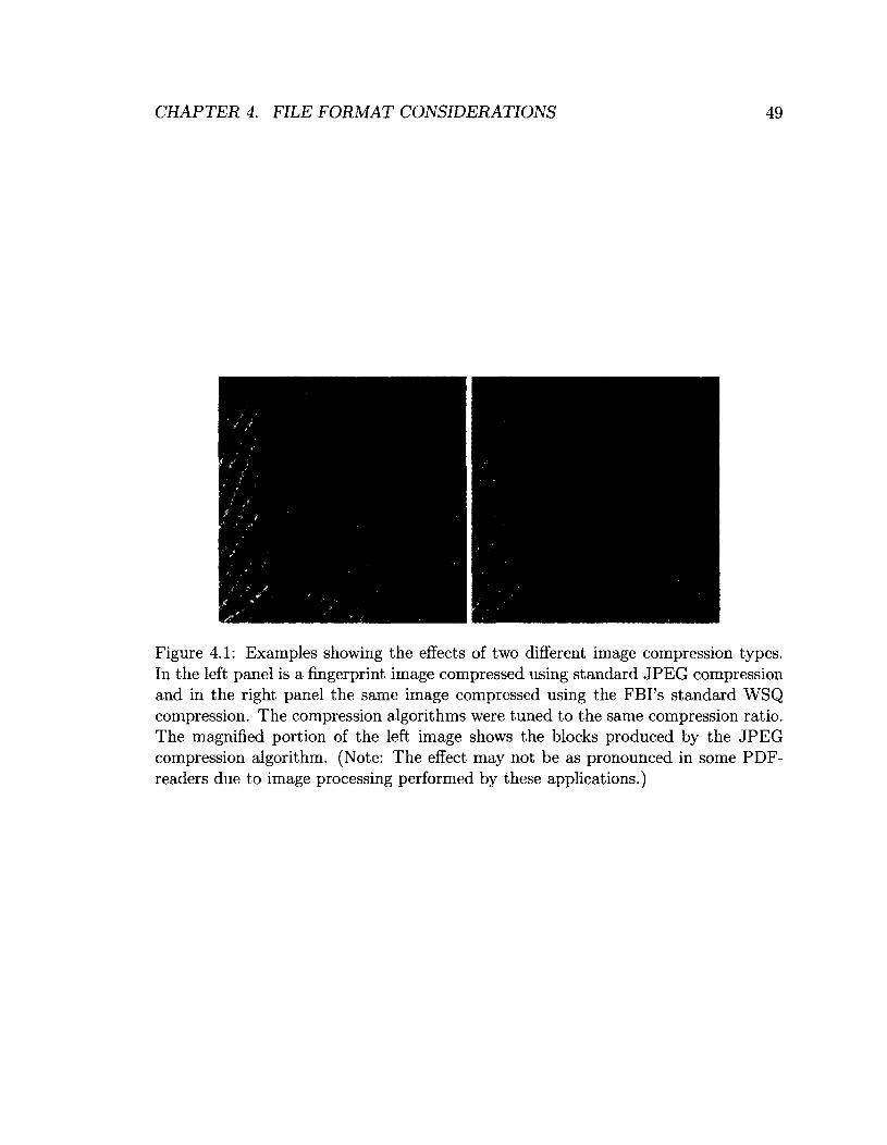
CHAPTER 4. FILE FORMAT CONSIDERATIONS 49
Figure 4.1: Examples showing the effects of two different image compression types. In the left panel is a fingerprint image compressed using standard JPEG compression and in the right panel the same image compressed using the FBI's standard WSQ compression. The compression algorithms were tuned to the same compression ratio. The magnified portion of the left image shows the blocks produced by the JPEG compression algorithm. (Note: The effect may not be as pronounced in some PDF-readers due to image processing performed by these applications.)

CHAPTER 4. FILE FORMAT CONSIDERATIONS 50
4.4 File Formats Used in The Developed System
In addition to the WSQ image format, several other file-formats which are not com
monly used in fields other than fingerprint recognition are used in the system. These
formats include the XYT and MIN file formats, both of which are of the plain-text
file-type.
The XYT file-format stores minutiae. Each line of an XYT file represents a
minutia, with space delimited Cartesian coordinates, x and y, as well as the angle
of that minutia's most closely associated ridge, 8, and finally the "quality" of that
minutia, u. This file format is used by many fingerprint recognition algorithms [25]
and is the primary output of the "mindtct" program (this program is discussed in
more detail in Chapter 7).
The MIN file-format also stores minutiae, however it stores more features and
detail on each minutia than the XYT file-format. Each line represents a minutia, as
with the XYT files. Instead of being space delimited MIN entries are colon delimited.
The data stored for each minutia includes:
• A minutia "id" number.
• The x and y Cartesian coordinates.
• A discretized ridge angle value.
• A "reliability" measure.
• The minutia's type (ridge ending or bifurcation).
• The Cartesian coordinates of the nearest neighboring minutia.
• The ridge count between the represented minutia and its nearest neighbor.
The MIN format is used when more details about the minutiae are required by the
matching algorithm, each representation of the fingerprint's minutiae are available to
algorithms which are added to the developed system.

CHAPTER 4. FILE FORMAT CONSIDERATIONS 51
4.5 Chapter Summary
In this chapter we have discussed the file format considerations in the construction of
a fingerprint matching system. Although file formats are a minor topic, in this thesis,
it is still important to understand the most common fingerprint image and minutia
file formats as well as the challenges involved in storing them. This will permit the
integration of biometric tools and algorithms.
Chapter 5
Pattern Recognition Methods
In the earlier chapters of this thesis, the components required to create a fingerprint
identification/verification system were described in detail, and various techniques for
accomplishing each step of the pertinent recognition phases were formulated. The
focus of the rest of this thesis is the matching phase of the fingerprint identification
process. This chapter covers the fingerprint matching algorithms that have been
implemented and used in the fingerprint identification system that we have developed.
These algorithms were chosen from the wide selection of methods reported in the
literature, and were implemented or procured through the use of open-source software.
The two main categories of minutiae matching algorithms were discussed in Sec
tion 2.6.4. In this regard, a brief survey of global and local techniques is provided in
Sections 5.1 and 5.2 respectively.
In this chapter, we will describe the operation of each of the algorithms which
have been implemented from previous works and subsequently integrated into the
fingerprint recognition system that we have developed.
5.1 Survey of Global Matching Techniques
The following is a brief survey of well-known global matching techniques. The in
tention of this section is to provide some background into the operation of these
acclaimed global matching algorithms.
52

CHAPTER 5. PATTERN RECOGNITION METHODS 53
5.1.1 Hough Transform
One of the most common global techniques are the group of Hough transform-based
matching algorithms. These techniques are often based on the Generalized Hough
Transform (GHT) analogous to the one reported in [34] (and mentioned in [1]), which
is used to adapt the fingerprint matching problem "onto" a simple noise-tolerant
point-to-point matching problem. An example usage of this technique can be found
in [24], and is also described in detail in Section 5.3.2.
5.1.2 Ridge Feature Alignment Approach
Another global technique reported by Jain et al. [30] uses a ridge-based feature align
ment approach, transforming the minutiae matching problem into a string matching
problem. The algorithm proceeds with the following steps:
1. Align the minutiae-based on their ridge features.
2. Convert the minutiae from each template into symbolic string representations:
Pp and (j)q.
3. Match the two strings using a dynamic programming algorithm.
4. Score the fingerprint based on the minimum edit distance between the two
strings.
The alignment, in turn, proceeds by using a property of a point-pattern and an
associated curve (in the case of a fingerprint, a ridge) to achieve an estimation of the
transformation parameters which align the two fingerprints [30]. The details of how
this achieved is omitted here to avoid confusion.
Conversion of the, now aligned, minutiae into strings is performed by sorting them
by using the increasing order of the angle of the most closely associated ridge. These
minutiae and their features are concatenated in this order to form symbolic strings
Pp and Qq.
An interesting feature of the matching process is that it uses adaptive bounding
boxes to tolerate distortion. The amount of distortion that it tolerates increases, as
CHAPTER 5. PATTERN RECOGNITION METHODS 54
necessary, at a given learning rate. This results in a slightly mobile bounding box
which can shift its location in order to accommodate local distortion due to skin
plasticity [30].
5.2 Survey of Local Matching Techniques
The following is a brief survey of some of the more well-known local-scheme matching
techniques. As with the section of global matching techniques, this section is intended
to provide some background in the area of local matching techniques.
5.2.1 Feature-Vector Based Matching
One of the oldest local-scheme algorithms for minutiae matching creates a feature
vector in order to represent each minutia, and was reported by Hrechak and Mchugh
[35]. This feature vector consists of information relating not only to the minutia
that the vector was created to represent, ra^, but also that minutia's neighbors. The
vector holds a series of numbers representing the quantity of each type of minutia
which is within the "neighborhood" of m*. The neighborhood is constructed by
collecting the minutiae which are within a radius r of wij. The feature vector is of
the form Vi = [vi) 1,1^2, • • • ,fi,s] where Vij represents the number of minutia of type j
found within the radius r of minutia rrii [35]. Eight different types of minutia were
considered, but we maintain that the type of minutia is considered an unstable feature,
as this feature (i.e., the type of a specific minutia) can be difficult to determine in an
automated fashion, and can be incorrectly recorded at even the image level as even
slight variance in pressure when the print is taken can change the interpreted type of
a minutia [1].
As mentioned in [1] and reported in [36], this feature vector technique can be
improved upon in several important ways. In addition to storing information about
the type of the minutiae in the local neighborhood of the central minutia m*; one
can store information about the distance from m* of each minutiae, the ridge count
between each minutiae and mthe direction in which the minutiae are relative to
CHAPTER 5. PATTERN RECOGNITION METHODS 55
r r i i , and the total number of nearby minutiae. This helps to counteract the instability
of the minutiae-type-feature, as well as compromise for different types of distortion
than accounted for by recording only the minutia type.
5.2.2 Adjacency Graph Matching
Another local technique reported by Ratha et al. [6] uses a "star-representation" of
minutiae, their local region and their structural relationships, to create a minutiae
adjacency graph. Once created, this adjacency graph would be used to perform
matching using weighted comparison techniques. In addition the algorithm uses two
phases for matching, a "strict matching" phase and an "extension phase".
The strict matching phase performs a weighted matching between minutiae pairs
with tolerances between each of their attributes. Angles of the edges from each star
are used, instead of the angles of the most closely associated ridge, in order to allow
the star minutia representation to be rotationally independent.
The "extension phase" involves improving the certainty of matches by accumu
lating more evidence. Matches obtained through the strict phase are extended using
matching techniques with relaxed thresholds.
This two phase matching system was designed primarily to mimic the way a
fingerprint expert might examine a fingerprint. By first selecting a minimum set of
minutiae (from both fingerprints) which can be reliably matched, he would employ
a basis for expanding the amount of evidence which corresponds between the two
fingerprints.
An improvement of this technique is reported in [25]. This improvement is known
as the "K-plet" representation, and is discussed in detail in Section 5.3.3.
5.2.3 Geometric Clustering-Based Matching
This matching technique is based on using a fuzzy bipartite graph to match the two
fingerprints and was reported by Fan et al. [37], The query fingerprint's minutiae
constitutes one of the independent sides of the bipartite graph, and the database
fingerprint's minutiae represents the other independent side of the bipartite graph.

CHAPTER 5. PATTERN RECOGNITION METHODS 56
The minutiae are clustered using the maximin algorithm reported in [38] into
bounded boxes. Important attributes of each of these clusters are then themselves
measured.
These characteristics are used to distinguish between different clusters and include
the following: NOB; which is the number of bifurcations in Cj, NOE; which is the
number of endpoints in c*, WH; which is the ratio of the width over the height of the
rectangular bounding box of c<, OT; which is the orientation angle of all ridge pixels
in Ci, and Sk; which are 20 different measurements based on the results from different
5x5 masks [37].
Each of these attributes, along with the minutiae clusters, are converted into repre
sentations of fuzzy sets, each possessing their own membership function to determine
a "degree of belonging". The optimal solution to the matching of the two fingerprints
using this technique is the minimum cost between the corresponding nodes in the
graph [37].
5.3 Implemented Recognition Methods
Several techniques were implemented in the system which we have developed. These
include a technique based on the GHT, one based on matching local graphs, and the
bozorth3 algorithm1. These methods were either implemented from fundamentals or
obtained from open-source software so as to be used with the system. This section
describes some of the major decisions made during the development and integra
tion process, as well as the operating details of the implemented/included matching
techniques.
5.3.1 Development Notes
The programming language chosen for the development of the algorithms was C++.
It was chosen because it is widely used, and produces very fast binaries, and it should
be beneficial in the event that another party should wish to use the implementation
1Also referred to as Bozorth's algorithm.

CHAPTER 5. PATTERN RECOGNITION METHODS 57
at a later time. The drawback of the language choice is that C++ is a poor choice for
prototyping due to its development cycle. As a result, for the purposes of prototyping,
we used the language Common Lisp. Common Lisp's highly dynamic runtime per
mitted rapid development and re-factoring on a "live" system. Once the prototypes
reached a level which indicated that the technique was implemented properly and
functioned as indicated in the relevant literature, they were translated to C++.
We also developed a complete library for parsing XYT and MIN files using the cl-
ppcre library, so as to accomplish the data extraction with regexps. This XYT/MIN
parser was later translated to C++ using the widely used Boost library collection for
regexp support.
5.3.2 Global-Scheme: Hough Transform Alignment-based Match
ing
Hough Transform techniques are often used in image processing and pattern match
ing algorithms. The Hough Transform is essentially a feature extraction technique,
frequently used for tasks such as line and edge detection. In a pattern matching al
gorithm, such as fingerprint matching, one can use the GHT to perform elastic point
pattern matching as described in [34] and used in [24],
Generalized Hough Transform
The regular Hough Transform can only be used to detect objects that can be described
with an equation2, whereas the GHT can be used to detect arbitrary objects described
with a template and with a set of appropriate transformations.
The GHT, as applied to the minutia matching problem, is simply a mapping of
one minutiae set to another [24]. The goal is to find an appropriate transformation
from the query template's minutiae to each database fingerprint template. Consider
two minutiae sets [24]:
2Hough Transforms have been used to detect lines, circles and other similar objects.

CHAPTER 5. PATTERN RECOGNITION METHODS 58
where V is one of the database template's fingerprint sets, and Q is the query
fingerprint template's minutiae set. In order to match these two sets of points to
gether, the space of all possible transformations (sometimes referred to as the Hough
Space) of the point-set are defined by the following transformation parameters: scale
(s), rotation (</>), and Cartesian displacement (Ax, and Ay). The Hough Space is
obviously infinitely large and must be restricted in order to deal with the complexity
of exploring it. The Hough Space is restricted based on knowledge of the problem
domain. For example, it has been empirically determined that rotational noise of fin
gerprints in a fingerprint database does not often exceed ±20% [39]. With restrictions
like this in place, the range of accepted transformation parameters is discretized. The
transformations themselves are all of the form shown in Eq. (5.1) [24]:
^ I x\ ( cos <t> sin d> \ ( x\ ( Ax \ FsrfAxAv ( ) = S ( f A)( ) + ( a J" ^
\ y ) \ - s m <j) COS0 J \ y J \ Ay J
In order to determine the best parameters to give the transformation from V into
Q we used Algorithm 5, which was reported in [24], The algorithm iterates through
all possible pairings of points between V and Q and subsequently uses each of the
discretized values of 0 G $ which will bring po to within tolerance of qe- Once it finds
these values of <j> it iterates through each of the possible values of s and solves for
Ax and Ay using Eq. (5.1). Once each of the values of s, <j>, Ax, and Ay have been
determined, a vote is cast into the bin representing these transformation parameters
within the Hough Space3, A [24],
Once each combination of minutia pairs from V and Q have been attempted, the
transformation with the most votes in its bin is chosen. Subsequently, the minutia
matching algorithm becomes a simple point-matching problem [34].
An example of the alignment transformation produced by Algorithm 5 between
two fingerprints from the FVC2002 database is shown in Figure 5.1.
3As well, votes are cast into nearby bins in order to reduce the algorithms sensitivity to noise and improve its overall results.

CHAPTER 5. PATTERN RECOGNITION METHODS 59
Figure 5.1: Diagram showing the alignment produced by Algorithm 5. The top two images depict the two fingerprints, from the same digit, with their detected minutiae, and the bottom image is the resulting alignment between the two sets of minutiae. One set of the minutiae is coloured green with its 6 indicator coloured orange, while the other set of minutiae is coloured red with its 6 indicator coloured blue.

CHAPTER 5. PATTERN RECOGNITION METHODS 60
Algorithm 5 Hough Transform to Determine Best Transformation Parameters. Input 1: V: First Minutiae set, which may either be from the query template or the database's template, image. Input 2: Q: Second Minutiae set, either from the query template or the database's template. Output: {s, <fi, Ax, Ay}: The transformation parameters required to transform minutiae set V into minutiae set Q. A(s, <j), Ax, Ay) 0 {Initialize Hough Array} S [smin => smax] {Array of discretized s values} $ {(pmin => <f>max\ {Array of discretized 4> values} for p e V do
for q G Q do for (/>£<$> do
cast_votes(s, <fi, Ax, Ay) end for
end if end for
end for end for return (index_of_maximum(^4))
if within_tolerance(pe + <p) then for s € S do

CHAPTER 5. PATTERN RECOGNITION METHODS 61
The Point-Matching Problem
Once transformed, all that must be done to fully match one fingerprint against the
other is to do an N x M comparison of the query template fingerprint's minutiae
against the database fingerprint's minutiae. Two minutia points are considered a
match if they satisfy the two requirements in Eq. (5.2) and Eq. (5.3) where r is
the similarity threshold between the angles of two different minutiae and 5 is the
threshold on the Euclidean distance between two different minutiae.
r > min(|pe + q6\, 360 - \pe - qe|) (5.2)
& > \ J ( Q x - P x f + ( q y ~ P y )2- (5.3)
The implemented point-matching algorithm uses a pseudo best-match algorithm.
The algorithm pairs each minutia with its "best-match" from the remaining set, and
then removes that match from the minutiae checked by subsequent point matches.
This will obviously not obtain the best matching pairs but will approximate the best.
This algorithm is summarized in Algorithm 6.
Once all the minutiae have been paired with their approximate "best" matches,
the match score is computed. The method of computing the match score is listed
in Eq. (5.4). This is a common method of computing the match score between two
particular fingerprints. The paired fingerprints which score above a certain threshold
are considered to be matching.
~5r3r -
where "results" is a vector containing the matched minutia pairs4.
Development Notes
When the algorithm was originally implemented it was found to take an average
of 30 seconds, on the available machines, to compute the match score between two
4We use the absolute value operators "||" indicate the size of a set when they are applied as such. Otherwise when applied to a normal value it is to indicate the "absolute value" of that value.
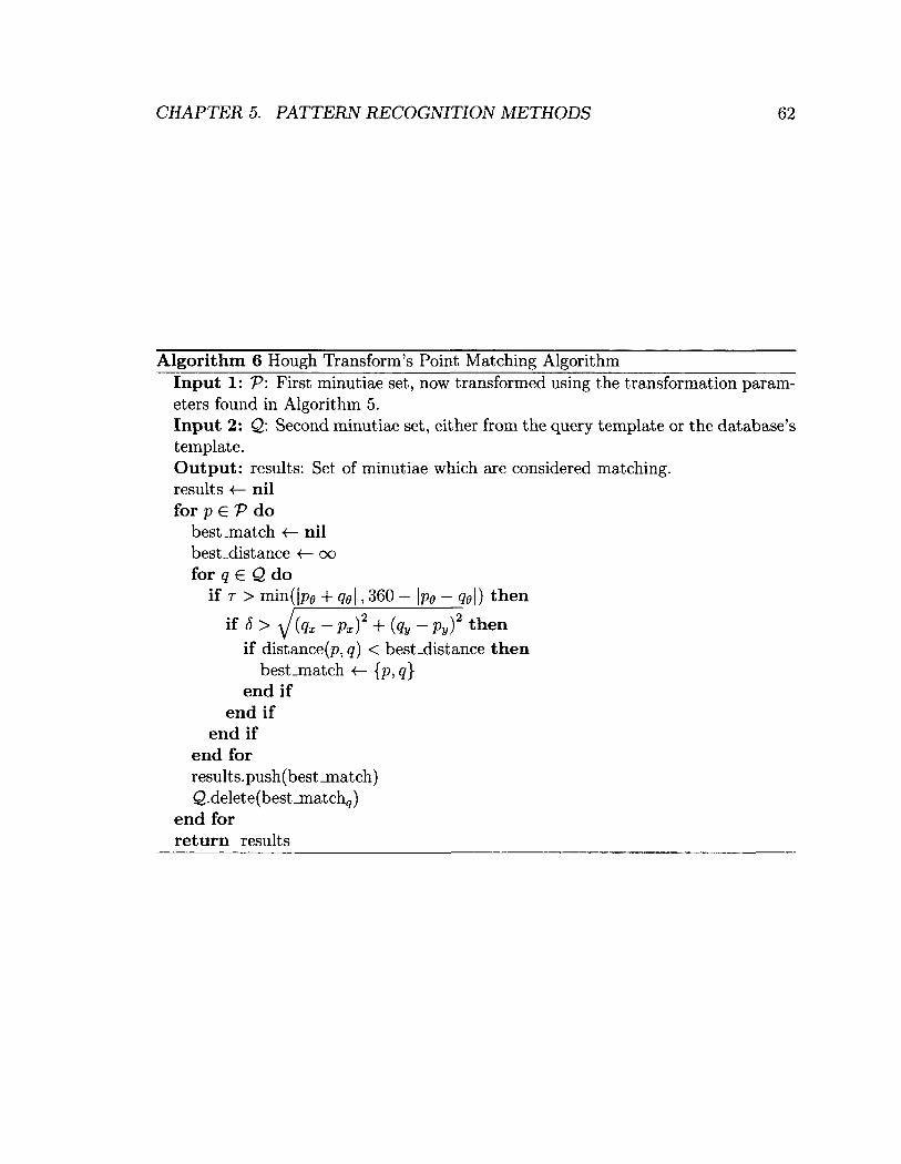
CHAPTER 5. PATTERN RECOGNITION METHODS 62
Algorithm 6 Hough Transform's Point Matching Algorithm Input 1: V: First minutiae set, now transformed using the transformation parameters found in Algorithm 5. Input 2: Q\ Second minutiae set, either from the query template or the database's template. Output: results: Set of minutiae which are considered matching. results <— nil for p EV do
best_match <— nil best_distance <— oo for q € Q do
if T > min(|PE + qg\, 360 - \p0 - q6\) then
end if end if
end for results. push (best _match) Q.delete(best_match9)
end for return results
if distance^, q) < best-distance then best_match 4— {p, q}
end if

CHAPTER 5. PATTERN RECOGNITION METHODS 63
fingerprints. This execution time is approximately two orders of magnitude larger
than that of the execution time of the bozorth3 algorithm from the NBIS package.
In an attempt to improve the speed of the Hough transform-based algorithm, the
parameters of the algorithm were adjusted. Observe that the adjustable parameters
of the Hough algorithm include the following:
• The maximum size, minimum size and resolution of the discretized scaling fac
tors smin, smax and sn respectively.
• The maximum and minimum rotation of the angle of the most-closely associated
ridge, fimin &nd <Pmax•
• The maximum and minimum horizontal displacements xmin and xmax.
• The maximum and minimum vertical displacements ymin and ymax •
These parameters define the size of the Hough array and are the constants affecting
the number of iterations required by Algorithm 5. The initial parameters were gener
ous and included scaling up to ±30% (smin = 0.7, smax = 1.3 and sn = 0.1), rotation
up to 360° in both directions (cf)min — —360, and 0maz = 360), and displacement up
to 300 pixels (xm{n ymin 300, xmax — ymax = 300).
The parameters which affect the number of iterations required by Algorithm 5
include smin, smax, sn, 4>min and <j)max. Fingerprint images vary in orientation by
approximately ±20° [8, 40], which gives (pmm = —20 and (j)max = 20. The rest of the
parameters were adjusted by observing the transformation parameters chosen by the
algorithm itself. The maximum parameters chosen for a matching pair of fingerprints
was used to choose appropriate values, giving: smin = 0.98, smaz = 1.02, sn = 5,
Xmin = -100, Xmax = 100, ymin = -100 and ymax = 100. By using these modified
parameters, the execution time of the algorithm was brought to be within milliseconds
of the speed of the bozorth3 algorithm.
During tuning we noted a distinct drop off point where the hough transform ceased
to produce suitable point alignments for matching. It was difficult to determine an
exact level of noise which produced this behavior but the phenomenon was noted
several times throughout the tuning process.
CHAPTER 5. PATTERN RECOGNITION METHODS 64
5.3.3 Local-Scheme: K-plet Representation Matching
The K-plet representation-based matching algorithm is similar to other local-scheme
minutia matching algorithms. As with other local-schemes, the K-plet algorithm
creates structures from localized minutiae and performs comparisons on the collection
of localized structures of the two fingerprints.
K-plet Representation
The K-plet representation is at the core of the algorithm. The representation is
like that of a similar algorithm which uses "star-like" graphs as local structures for
comparing fingerprint minutiae by Ratha et al. [6]. The K-plet representation uses a
central minutia m* and K neighbors {mi, ra2,. • •, ttik} to create a graph, referred to
as G. The minutiae are represented as three-tuples dij, rlv } where 4>l3 represents
the angle of the edge connecting mi and rrij relative to the horizontal, represents
the relative orientation of minutia r r i j with respect to the central minutia r r i i , and r i j
is the Euclidean distance between minutia m* and minutia r r i j .
Two methods are given by Ratha et al. [25] for the construction of the local K-plet
structures.
• The first method is based on determining the K neighbors in terms of their
Euclidean distances. This method was found to work fairly well and is simple
to implement [25]. The drawbacks of this method is that it does not spread the
minutiae contained within the K-plet structure across the fingerprint, reducing
the discriminating power of the structure [25].
• The second method was created to provide a "higher-connectivity" between
disparate portions of the fingerprint. K neighboring minutiae are selected such
that the nearest neighbor is picked from separate quadrants instead of being
chosen purely based on proximity [25].
Once a K-plet structure has been constructed for each of the minutia in the finger
p r i n t , t h e i r l o c a l s t r u c t u r a l r e l a t i o n s h i p s a r e c o m p o s e d i n t o a d i r e c t e d g r a p h G ( V , E ) .
Each vertex v represents a minutia and each edge (u, v) represents the neighboring

CHAPTER 5. PATTERN RECOGNITION METHODS 65
minutia as defined by that minutia's K-plet structure. Each vertex u is colored with
attributes (xu,yu,6u,tu), where xu and yu are the Cartesian coordinates, 9U is the
orientation of the minutia, and tu is the minutia type [25].
Graph Matching Algorithm
Once the graphs have been constructed for both of the fingerprints in question, the
actual task of matching the two graphs can be accomplished. Matching proceeds
through the use of a dynamic programming technique based on the string alignment
problem. Instead of matching the local K-plet structures (which are now represented
by nodes and their outward facing edges in the graph) separately, the structures (or
nodes of the graph) are matched simultaneously. This is important as it has been
determined that matching structures in greedy fashion is sub-optimal [6, 25].
In order to match the K-plets in a stable manner, the neighbors of the K-plet's
central minutia are sorted in increasing order of the magnitude of their Euclidean
distances from the central minutia. This transforms the graph matching problem to
that of matching two ordered sequences (as in the string alignment problem) [25].
The groups of K-plets can now be represented as two ordered sequences S and T.
To solve the alignment problem, the original sequences must be transformed into two
sequences S' and T" which have the following properties [25]:
1. S' is formed from S by adding spaces as necessary.
2. T" is formed from T by adding spaces as necessary.
3. |5'| = \T'\.
The dynamic programming-based approach to solving this problem is as follows:
Let the cost of aligning sub-strings S(l...i) and T(1... j) be given by Eq. (5.5).
The cost of aligning the entirety of both strings S and T can therefore be given by
D[M,N] [25].
D [ i , j ] : i € { 0 , 1 . . . M } , j £ { 0 , 1 . . . N } . (5.5)

CHAPTER 5. PATTERN RECOGNITION METHODS 66
The recurrence relation between D[i, j] and the already computed values is used
to reduce the run-time, where D[k,l] is optimal Vfc < i,l < j. Once all previous
sub-problems have been solved, Sj and tj can be matched in a number of ways [25]:
1. A cost of c(s[i],£[7']) can be introduced between the elements s[z] and t [ j ] .
2. A gap in the string T can be inserted with cost er(,s[i], _).
3. A gap in the string S can be inserted with cost cr(_, t [ j ] ) .
Consolidation Approach
Another important part of the K-plet algorithm is its associated consolidation algo
rithm, Coupled Breadth First Search (CBFS). The algorithm is based on a breadth
first search philosophy as its name suggests, except for two factors [25]. First, traver
sal occurs in two graphs G and H, which have been constructed from the K-plets,
simultaneously. Second, the standard breadth first search will visit each vertex in the
adjacency list, whereas the CBFS algorithm only visits vertices vq and vH from G
and H where Vq and vH have been successfully matched.
The CBFS is shown in Algorithm 7, where VQ and V H are the sets of vertices in
graphs G and H respectively, match_neighbors() attempts to matches neighbors and
returns the list of those matched neighbors, and color(-y) accesses the color of vertex
v.
Since the CBFS algorithm requires two starting nodes i and j, and the optimal
starting nodes are not known, the CBFS is run with all possible starting nodes in the
graphs. The pair of starting positions which yield the greatest number of matches are
stored and used to produce a matching score. Once the CBFS algorithm has com
pleted, the returned matched minutiae vector, M, is used to compute the matching
score [25]. The size of the matched minutiae vector, |M|, is used in Eq. (5.6) in a
similar manner to that used in the Hough-transform-based algorithm in Section 5.3.2
in Eq. (5.4).
score = \M\2
(5.6) I P I - I C I
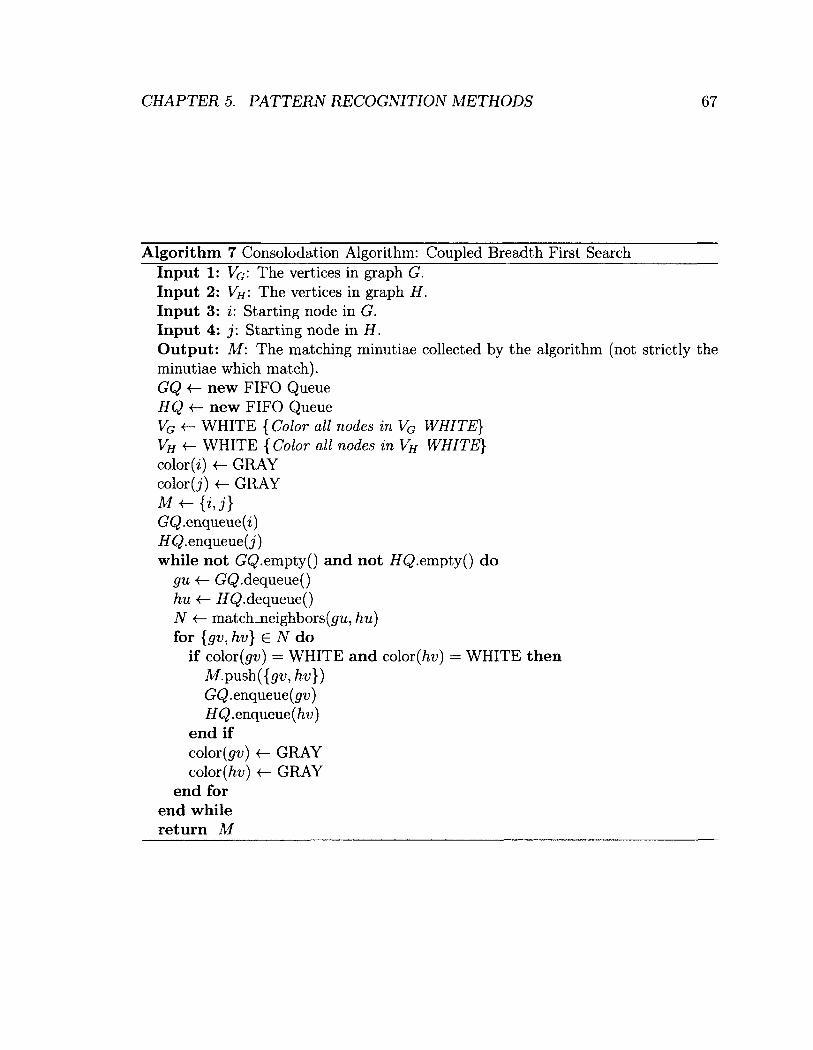
CHAPTER 5. PATTERN RECOGNITION METHODS 67
Algorithm 7 Consolodation Algorithm: Coupled Breadth First Search Input 1: Vq: The vertices in graph G. Input 2: VH: The vertices in graph H. Input 3: i: Starting node in G. Input 4: j: Starting node in H. Output: M: The matching minutiae collected by the algorithm (not strictly the minutiae which match). GQ -f- new FIFO Queue HQ new FIFO Queue VG «- WHITE {Color all nodes in VG WHITE} VH <- WHITE {Color all nodes m VH WHITE} color (i) GRAY color (j) <r- GRAY M + - { i , j } GQ.enqueue(i) HQ. enqueue (j) while not GQ-empty() and not HQ.empty() do
gu <— GQ.dequeue() hu <— HQ.dequeue() N •<— match_neighbors(g'u, hu) for { g v , h v } G N do
if color(^) = WHITE and color(H = WHITE then M . p u s h ( { ^ t ; , h v } ) GQ.enqaeue(gv) HQ. enqueue (hv)
end if color (pv) •<— GRAY color (/if) <— GRAY
end for end while return M
CHAPTER 5. PATTERN RECOGNITION METHODS 68
Development Notes
Much of the included implementation of the K-plet representation-based algorithm
is from the publicly available implementation developed by the original authors of
the algorithm, Chikkerur et al. In order to ensure fairness in the comparison of the
discriminating ability of the matching algorithms implemented as part of this thesis,
a number of changes had to be applied to the original K-plet algorithm. Adjustments
were made to the parameters of the algorithm to prevent it from using more distinctive
information than the other algorithms had available. The only information available
from the minutiae sets for all algorithms include the Cartesian coordinates of each
minutia and the angle of the most closely associated ridge. As mentioned in [25] the
source-code for the algorithm is available online. The only other significant changes
required involved the usage of the developed XYT/MIN parser.
5.3.4 Local-Scheme: Bozorth's Algorithm
The last algorithm used in the fingerprint recognition system that we developed is the
algorithm devised by Bozorth from the NIST. This was created as part of their NBIS
package for aiding in the production of standards in fingerprint identification/verifi
cation technology. This algorithm is known as "bozorth3", "the Bozorth algorithm"
or "Bozorth's Algorithm" and is a local-scheme.
The bozorth3 algorithm was developed as part of a demonstration to be used in
the National Crime Information center [39]. Although it was originally intended only
for demonstration purposes, it proved to be an effective method of distinguishing
fingerprints, and is now popularly used as a benchmark for fingerprinting technology
[39].
The only features which are used by the bozorth3 algorithm are the Cartesian
coordinates and the angle of the most closely associated ridge. This makes it another
good candidate for benchmarking the performance of the novel technique developed
as part of this thesis.
The steps involved in the algorithm are the following [39]:
CHAPTER 5. PATTERN RECOGNITION METHODS 69
1. Tables are constructed for both the query and database fingerprints. These ta
bles contain feature information about each minutia relative to all other minu
tiae. These tables are referred to as "Intra-Fingerprint Minutia Comparison
Tables".
2. Prom these two tables, a new "Inter-Fingerprint Compatibility Table" is con
structed. Feature information which was found to be compatible between the
two Intra-Fingerprint Minutia Comparison Tables is encoded within the Inter-
Fingerprint Compatibility Table.
3. The Inter-Fingerprint Compatibility Table is then traversed. The Inter-Fingerprint
Compatibility Table is analogous to a "compatibility graph", where the associ
ations between the two fingerprints represent edges in the graph. The longest
chain of these is used as the matching score of the fingerprint.
The feature information which is included in the Intra-Fingerprint Minutia Com
parison Tables is related to the relative position and 9 values of each possible minutia
pair. For each pair, six different measurements are used, which are the angle between
each minutia's most closely associated ridge and a line-segment drawn between the
two minutia, the angle between the line-segment and the horizontal axis, the Eu
clidean distance between the two minutiae, and the Cartesian coordinates of the two
minutiae [39].
The traversal in Step 3 can be achieved using an interesting approach to solve some
of the problems inherent with the compatibility graph constructed through invoking
Steps 1 and 2. Some of the issues which the designers had to overcome have been
outlined in [39], for example:
• The graph is very disjoint, consisting of many clusters which consist only of a
single edge connecting two verticies.
• The maximum potential number of edges for each node is very high, and grows
with the number of minutiae.
• The graph has the potential of being cyclic.
CHAPTER 5. PATTERN RECOGNITION METHODS 70
Several more issues associated with the algorithm are listed in [39], but the above
stand out as being the most difficult ones which have to be overcome. The solution
created by Bozorth (reported in [39]) is to begin the traversals of the graph from a
number of different starting locations, and creating additional edges between different
nodes as the algorithm progresses through the graph. The additional edges form
clusters of nodes which are combined in a consolidation step, resulting in a set of
unique clusters. The number of linked nodes in the clusters is used as the match
score [39].
5.4 Chapter Summary
In this chapter we have discussed several different pattern matching methods used in
the fingerprint matching field of study, as well as discussed all but one of the pattern
matching methods used in the fingerprint matching system developed as part of this
thesis.
Chapter 6
Subsequence-Tree-Based Methods
This chapter includes the relevant background information as well as the design pro
cess/rationale of a novel pioneering algorithm developed as part of this thesis. This
novel strategy to fingerprint matching was developed as a method of evaluating the
algorithm reported in [5], which itself was presented as a solution to the problem
of recognizing the source of noisy subsequence trees. We have adapted this for the
fingerprint matching problem.
First we will introduce and define the noisy subsequence tree recognition prob
lem (NSTRP). Subsequently the similarities between the NSTRP and the fingerprint
matching problem will be discussed. Finally, we will develop and evaluate a strat
egy for adapting the noisy subsequence tree recognition algorithm (NSTRA) to the
fingerprint matching problem.
6.1 Noisy Subsequence Tree Recognition Problem
The basis of this new approach to fingerprint matching, especially in noisy environ
ments, is the noisy subsequence tree recognition algorithm developed by Oommen et
al [5]. This algorithm was developed to solve a particular problem best described by
way of an example [5]:
Suppose we have a large database of ordered trees, H. Let X be an arbitrary
71

CHAPTER 6. SUBSEQUENCE-TREE-BASED METHODS 72
tree from H, and U be an arbitrary subsequence-tree obtained by randomly delet
ing nodes from X. The resultant tree (called a subsequence-tree or SuT of X) is
further subjected to substitution, insertion, and deletion errors yielding the Noisy
subsequence-tree (NSuT), Y. Our aim is then to identify the original tree, X, by
processing Y.
Since the noisy tree Y was produced, not from the original tree itself, but from
a subsequence-tree, it should be compared against the subsequence-tree from which
it was created. Such a solution strategy would add significant complexity, since the
source tree of Y is unknown, it would have to be compared with every possible
subsequence-tree of X, which is, indeed, an exponentially large number of configu
rations. One method of counteracting this complexity is to include the use of infor
mation about the nature of the noise itself in the recognition of the original trees [5].
In order to accomplish this, the problem is parametrized based on the number of re-
labellings or substitutions that are expected to occur, which is correspondingly based
on the noise affecting the transmission channel. In the original paper, the possible
source tree, X € H, of a given noisy subsequence tree, Y, is determined using the
technique displayed in Algorithm 8. This algorithm uses the constrained edit distance
calculated using Algorithm 9, which, itself, uses the Const_T_Wt array produced by
Algorithm 10. The details of Algorithms 8 to 11 are omitted here to avoid repetition.
They can be found in the original paper by Oommen et al. [5].
6.1.1 NSTRP and Fingerprint Matching Problem Similari
ties
The original goal of the noisy subsequence tree recognition algorithm was to effectively
match subsequence trees to their source trees despite their having been subjected to
a significant amount of garbling. A model of this problem which was utilized by
the authors of [5] was the following: A "transmitter" sends a tree X over a noisy
channel; but prior to sending it, the "transmitter" deletes random nodes from the
tree, thus producing a subsequence tree U, which is subsequently transmitted through
the noisy channel, producing a noisy version of U, Y. The goal of the "receiver", who

CHAPTER 6. SUBSEQUENCE-TREE-BASED METHODS 73
Algorithm 8 Algorithm RecognizeSubsequenceTrees Input 1: H: The finite dictionary of trees. Input 2: L: The expected number of substitutions that can take place per transmission. Input 3: Y: A noisy subsequence tree. Output: The estimated source tree, X + E H, of Y. for X E H do
if L is a feasible value then LP I— L
else L P closest feasible value of L
end if T 4 { ^ p 1 , L p , L p - ( - 1 } Compute D T (X ,Y) using Algorithm Constrained_Tree_Distance
end for return X+, the tree minimizing D R (X ,Y)
Algorithm 9 Algorithm Constrained_Tree_Distance Input: Const_T_Wt[]: The array computed by Algorithm T_Weights. Output: D T (T 1 ,T 2 ) : The constrained distance where r = { L p — 1, Lp, Lp + 1}. Dt{Ti,T2) <— oo for s e {Lp - l,Lp,Lp + l} do
D T {T U T 2) <r- min(DT(T1,T2),Const_T_Wt[|Ti|][|T2|][s]) end for return J9r(Ti,T2)
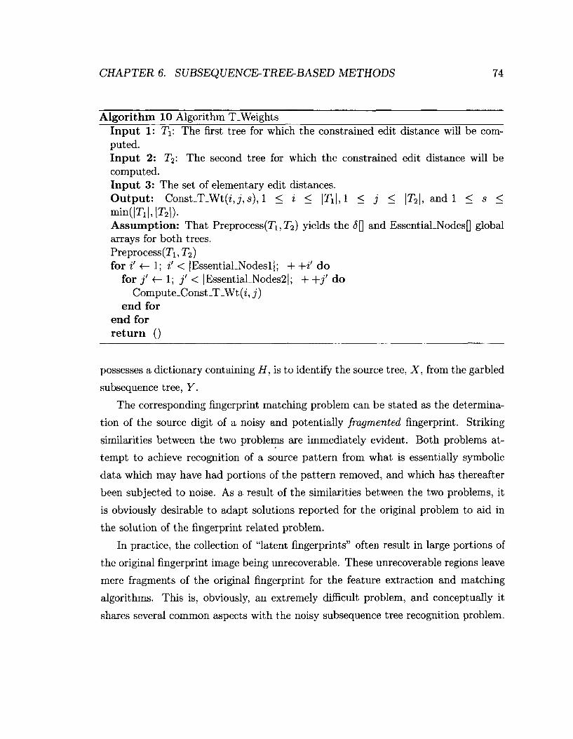
CHAPTER 6. SUBSEQUENCE-TREE-BASED METHODS 74
Algorithm 10 Algorithm T_Weights Input 1: T\: The first tree for which the constrained edit distance will be computed. Input 2: T2: The second tree for which the constrained edit distance will be computed. Input 3: The set of elementary edit distances. Output: Const_T_Wt(i,_;, s)> 1 < ^ < | JTI | , 1 < j < |T2|, and 1 < s < minflT.I.IT,!). Assumption: That Preprocess(Ti,T2) yields the 6[] and EssentiaLNodes[] global arrays for both trees. Preprocess(T\, T2) for i' 4— 1; i' < |Essential_Nodesl|; + +i' do
for j' <— 1; j' < |Essential_Nodes2|; + +j' do Compute_Const_T_Wt(2, j)
end for end for return ()
possesses a dictionary containing H, is to identify the source tree, X, from the garbled
subsequence t r ee , Y.
The corresponding fingerprint matching problem can be stated as the determina
tion of the source digit of a noisy and potentially fragmented fingerprint. Striking
similaxities between the two problems are immediately evident. Both problems at
tempt to achieve recognition of a source pattern from what is essentially symbolic
data which may have had portions of the pattern removed, and which has thereafter
been subjected to noise. As a result of the similarities between the two problems, it
is obviously desirable to adapt solutions reported for the original problem to aid in
the solution of the fingerprint related problem.
In practice, the collection of "latent fingerprints" often result in large portions of
the original fingerprint image being unrecoverable. These unrecoverable regions leave
mere fragments of the original fingerprint for the feature extraction and matching
algorithms. This is, obviously, an extremely difficult problem, and conceptually it
shares several common aspects with the noisy subsequence tree recognition problem.
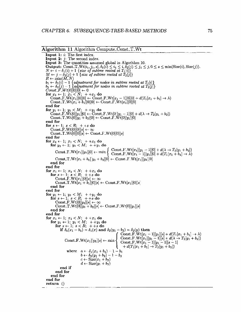
CHAPTER 6. SUBSEQUENCE-TREE-BASED METHODS 75
Algorithm 11 Algorithm Compute_Const_T_Wt The first index.
j: The second index. Input 1: Input 2: Input 3: The quantities assumed global in Algorithm 10. Output: Const_T_Wt[ii, ji, s], <5i(i) < i \ < i , f o i j ) < j i < j , 0 < s < min(Size(i),Size(j)). N <r- i — 6i(i) + 1 {size of subtree rooted at T\ [i]} M < - j — S 2 ( j ) + 1 { s i z e o f s u b t r e e r o o t e d a t T ^ f j ] } R «— min(M, N) bi «- Si(i) - 1 &2 — 1 Const-F-Wt{0}
1
adjustment for nodes in subtree rooted at Xi fi]} adjustment for nodes in subtree rooted at iVb'J}
. 'fo][o] <-o for x\ <- 1; ii < N; + +xj do
ConstJF_Wt[xi][0][01 Const_F_Wt[xj — 1][0][0] + d(T\ [xi + &i] ->• A) Const_T_Wt[xi 4- OiJ[0][0] <— Const J?_Wt[xi][0][0]
end for for yi «- 1; yx < M; + +t/i do
ConstJF.Wt[0l[j/i][0] 4- Const_F_Wt[0][yi - 1][0] + d ( A -4 T 2 [ y i + & 2 ] ) Co nst _T _Wt [0J \y \ + 62][0] Const _F_Wt[0][yij[0]
end for for s <— 1; s < R; + +s do
oo <- Const_F_Wt[0] [0] [s]
Const_F_Wt [01 [Oj is Const _T_Wt [0] [0j [s
end for for xi -<— 1; a?i < iV; + +x\ do
for yi <- 1; t/i < M; + +yi do
Const_F-Wt[xi][j/i][0] <— min |
• ^i] [j/i + ^2] [0]
' x i ] [ y i - 1 xi - l][j/l
Const _F_Wt [x 1 ] [yi ] [0
Const _F_Wt Const _F_Wt
Const_T_Wt[xj end for
end for for xi 1; Xi < iV; + +xi do
for s <— 1; s < R; + +s do Const_F-Wt[xi][0][sj <— 00 Const_T_Wt[xi + ] 1-
end for end for for yi <- 1; yi < M; + +yi do
f o r s «— 1 ; s < R; + + s d o Const J?_Wt[0lh/i][s] «— 00 Const_T-Wt[0][yi + 62] [s] «-
end for end for for xi «- 1; xi < N; + +xi do
for yi <r- I; yi < M; + +yi do for s <— 1; s < R; + +s do
if (Si(xi + b 1) = <5j(x) and <52(yi + 62) = S i ( y ) then
d ( A T 2 [ V l + f e 2 ] ) d(Ti [xi + 61] —^ A)
Const-F-Wt[xj] [0] [s]
Const _F.Wt[0] [t/i] [s]
Const_F_Wt[xi][j/i][s] «— min <
Const_F-Wt Const_F_Wt Const _F_Wt
xi - 1] [2/1 xi}[yi - 1
where
end if end for
end for end for return ()
CL I— <5I(XI &I) — 1 — BI b ^2(2/1 + b2) - 1 - 62 c <— Size(xi + 62) d <— Size(yi + 62)
Xi - 1] [j/1 - l][s - 1] 4- d{Ti\xi + 61] —• + 62])
+ d(T\ [x\ + f>x] —> A) + d { A - > T ^ l v i + ̂2 ] )
CHAPTER 6. SUBSEQUENCE-TREE-BASED METHODS 76
6.2 Adapting Noisy Subsequence Tree Recognition
The algorithm reported in [5] is a general purpose pattern recognition technique that
can be applied to several different application domains. The fingerprint recognition
(identification/verification) problem has the potential of being one of applications.
The algorithm for determining the source pattern for a noisy subsequence tree can
be regarded as a black box tree matching algorithm with high tolerance for noise in
the query subsequence tree.
The algorithm's reported robustness in the presence of large noise renders it to be
an ideal candidate for research in the area of latent fingerprint recognition. Recovery
of latent fingerprints often leads to large portions of the fingerprint being unusably
noisy. As already noted, this is analogous in spirit to the NSTRP in which unrecover
able information is randomly deleted from the fingerprint. The resultant fragmented
representation is further perturbed by the noise inherent in the fingerprint matching
problem.
The algorithm computes the so-called constrained edit distance between the orig
inal tree and the source tree, by taking into account what is known about the nature
of the "noisy channel" causing the errors. In order to utilize the algorithm in the
fingerprint matching problem, we must encode enough useful information from each
minutia and their local-spatial relationships into trees, which can then be matched
by the noisy subsequence tree recognition algorithm.
The task of encoding the minutiae and their local-spatial relationships into a
tree necessitates developing a method for symbolically representing a portion of this
information as the contents of the nodes of the tree, as well as determining how
the parent-child relationships between each of these nodes is generated. Ultimately
we must ensure that enough information is encoded within the tree's structure to
accurately match trees generated from the same finger. Both of these key design
decisions also require that the chosen features with which the trees are constructed
are resistant enough to noise so as to permit the stable encoding of their information
into trees. Choosing stable features ensures that the propagation of the instability of
known noisy features is kept to a minimum.
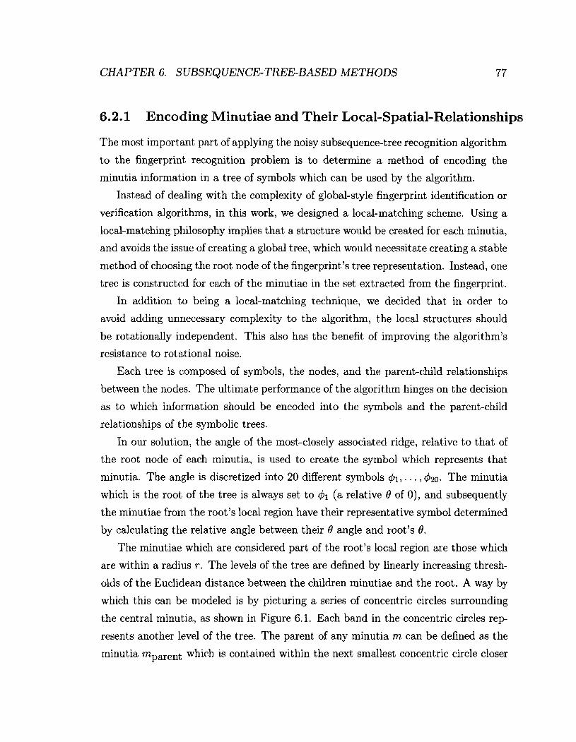
CHAPTER 6. SUBSEQUENCE-TREE-BASED METHODS 77
6.2.1 Encoding Minutiae and Their Local-Spatial-Relationships
The most important part of applying the noisy subsequence-tree recognition algorithm
to the fingerprint recognition problem is to determine a method of encoding the
minutia information in a tree of symbols which can be used by the algorithm.
Instead of dealing with the complexity of global-style fingerprint identification or
verification algorithms, in this work, we designed a local-matching scheme. Using a
local-matching philosophy implies that a structure would be created for each minutia,
and avoids the issue of creating a global tree, which would necessitate creating a stable
method of choosing the root node of the fingerprint's tree representation. Instead, one
tree is constructed for each of the minutiae in the set extracted from the fingerprint.
In addition to being a local-matching technique, we decided that in order to
avoid adding unnecessary complexity to the algorithm, the local structures should
be rotationally independent. This also has the benefit of improving the algorithm's
resistance to rotational noise.
Each tree is composed of symbols, the nodes, and the parent-child relationships
between the nodes. The ultimate performance of the algorithm hinges on the decision
as to which information should be encoded into the symbols and the parent-child
relationships of the symbolic trees.
In our solution, the angle of the most-closely associated ridge, relative to that of
the root node of each minutia, is used to create the symbol which represents that
minutia. The angle is discretized into 20 different symbols (j)i,..., 020- The minutia
which is the root of the tree is always set to <f>\ (a relative 0 of 0), and subsequently
the minutiae from the root's local region have their representative symbol determined
by calculating the relative angle between their 9 angle and root's 6.
The minutiae which are considered part of the root's local region are those which
are within a radius r. The levels of the tree are defined by linearly increasing thresh
olds of the Euclidean distance between the children minutiae and the root. A way by
which this can be modeled is by picturing a series of concentric circles surrounding
the central minutia, as shown in Figure 6.1. Each band in the concentric circles rep
resents another level of the tree. The parent of any minutia m can be defined as the
minutia "^parent which is contained within the next smallest concentric circle closer

CHAPTER 6. SUBSEQUENCE-TREE-BASED METHODS 78
Figure 6.1: Diagram illustrating the concentric circles which define the levels of the minutia tree. The minutiae are highlighted with red squares, the angle of the most closely associated ridge is indicated with a blue line, and the child-parent relationships are shown in green.
to minutia m. Any band of the concentric circles which is empty is joined with the
next smallest circle so as to prevent the creation of an empty level of the tree. This
is illustrated in Figure 6.2. The exact method used to construct the trees is shown in
Algorithm 12.
The determination of appropriate values for the MAX_RADIUS and BAND-WIDTH
constants was accomplished by manually adjusting the values and observing the size
of trees produced for several test fingerprint minutiae sets. The minutiae tree gener
ation algorithm was tuned until the average tree size was 15 nodes with the values of
MAX-RADIUS and BAND-WIDTH set to 120 and 10 respectively.
Once a tree has been constructed for each minutia, a vector of the query finger
print's trees is compared against a vector of the database fingerprint's trees. Compar
ison is achieved through the usage of the noisy subsequence-tree matching algorithm,
which results in a constrained edit distance. The best-match (one with the lowest
edit distance) is used for each tree to match the minutiae together, which results in
a vector of matched minutiae, M. The size of the vector M, \M\, is used to calculate
the match-score between the two fingerprints in a similar manner to that of the other

CHAPTER 6. SUBSEQUENCE-TREE-BASED METHODS 79
Algorithm 12 Tree Creation Algorithm Input 1: p: Minutia which is to be the root of the tree. Input 2: V: Set of minutiae which will be used to create the tree. Output: p: The root minutia, now endowed with its found children. treeJevels <- make_list_size(MAX_RADIUS/BAND_WIDTH) for m G (V — p) do
if euclidean_distance(m, p) < MAXJIADIUS then tree Jevels [euclidean-distance(m, p) /B ANDJWIDTH] .push(discretize_angle(m))
end if end for for level e treeJevels do
if level.size() = 0 then level, delete ()
end if end for for node £ treeJevels [0] do
p.push-child(node) end for for i <r- 1; i < |treeJevels|; + +i do
firstJevel 4— treeJevels [i — 1] secondJevel <— treeJevels [i] for child € second Jevel do
min_distance euclidean_distance(child, first Jevel[0]) minjnode <— first Jevel [0] for parent £ first Jevel do
if min_distance > euclidean_distance(child, parent) then min.distance <— euclidean_distance(child, parent) min_node <— parent
end if end for min .node .push .child (child)
end for end for return p
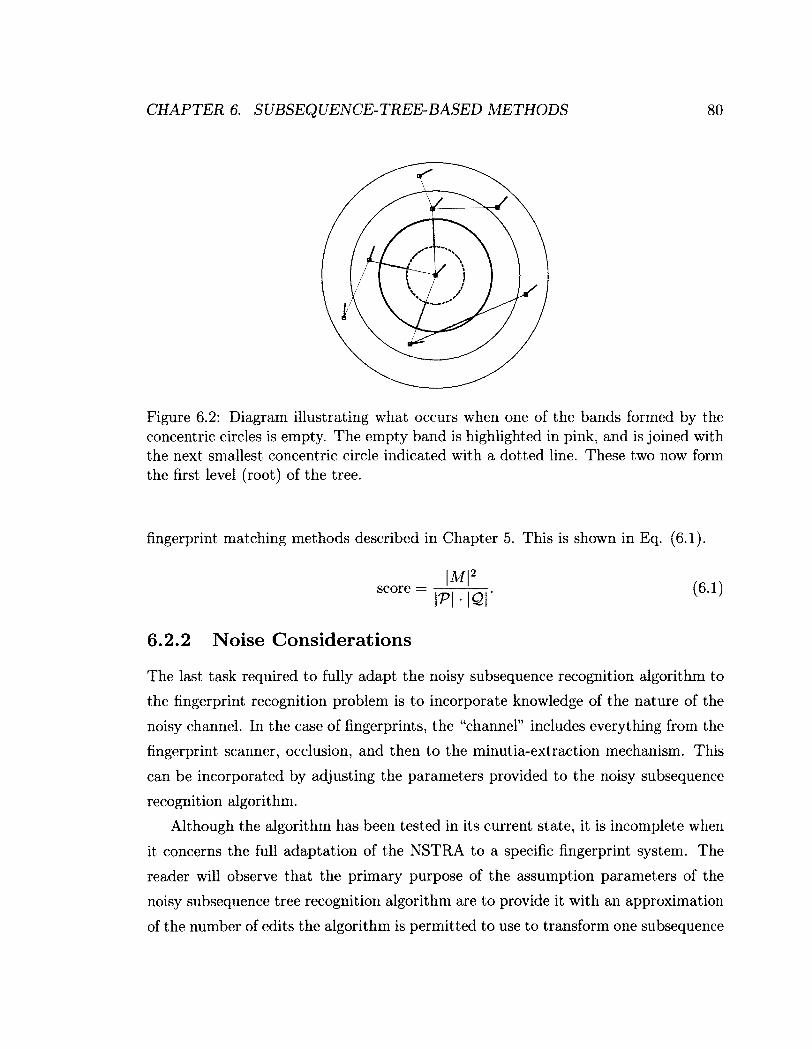
CHAPTER 6. SUBSEQUENCE-TREE-BASED METHODS 80
Figure 6.2: Diagram illustrating what occurs when one of the bands formed by the concentric circles is empty. The empty band is highlighted in pink, and is joined with the next smallest concentric circle indicated with a dotted line. These two now form the first level (root) of the tree.
fingerprint matching methods described in Chapter 5. This is shown in Eq. (6.1).
^ = iPMcr (fU)
6.2.2 Noise Considerations
The last task required to fully adapt the noisy subsequence recognition algorithm to
the fingerprint recognition problem is to incorporate knowledge of the nature of the
noisy channel. In the case of fingerprints, the "channel" includes everything from the
fingerprint scanner, occlusion, and then to the minutia-extraction mechanism. This
can be incorporated by adjusting the parameters provided to the noisy subsequence
recognition algorithm.
Although the algorithm has been tested in its current state, it is incomplete when
it concerns the full adaptation of the NSTRA to a specific fingerprint system. The
reader will observe that the primary purpose of the assumption parameters of the
noisy subsequence tree recognition algorithm are to provide it with an approximation
of the number of edits the algorithm is permitted to use to transform one subsequence

CHAPTER 6. SUBSEQUENCE-TREE-BASED METHODS 81
into another complete tree.
In order to choose the appropriate noise parameters for the algorithm, the noise
inherent in fingerprint recognition systems must be studied and understood. There
are a number of different sources of noise as already described in Chapter 2. In
summary these are:
• Rotation.
• Displacement.
• Distortion due to skin plasticity.
• Variance in pressure when the print is taken.
• Use of older fingerprint images.
• Differences in fingerprint collection techniques.
• Noise due to equipment operation or failure.
These sources of noise are modeled as affecting the unique subsequence fingerprint
as it is propagated through the "noisy channel", and which ultimately result in in
sertions, deletions, and substitutions in the tree representations of the minutiae. A
strategy for approaching this problem is elaborated upon in the discussion contained
in this Chapter.
6.3 Subsequence Algorithm Performance
Two main issues had to be taken into consideration when performing the experiments
to measure the performance of the developed algorithm. These involved eliminating
bias and mitigating the prohibitive runtimes involved.
Separate data was used for the training and the subsequent experimentation. This
ensured that there was no bias that resulted from the process of manually tuning each
of the algorithms.

CHAPTER 6. SUBSEQUENCE-TREE-BASED METHODS 82
Algorithm Accuracy Precision Recall FPR Bozorth's Algorithm 99.7% 98.7% 74.8% 0.00009 Hough Transform 99.3% 97.7% 34.5% 0.00007 K-plet 92.9% 10.1% 76.8% 0.07267 NSTRA-based 74.6% 2.7% 69.8% 0.17482
Table 6.1: Table outlining the overall Accuracy, Precision, Recall, and false positive rate of the implemented/procured algorithms.
In order to deal with the prohibitively high runtimes of "full runs" of the algo
rithms against the database of fingerprints1, a subset of cardinality 800 of the full
database was used for the experimentation. Also, in order to mitigate, as much as
possible, the influence on the results by our selection process, random images were
selected from the database to form this subset, and the same random subset was used
to test each of the fingerprint matching algorithms.
There are a number of metrics which can be used to compaxe the relative per
formance of one matching algorithm with respect to another. Ultimately, the per
formance of a particular fingerprint matching algorithm is highly dependent on the
quality of the fingerprints in question. The variance in the quality of the fingerprint,
as well as in the type of noise or damage afflicting a particular fingerprint, may have
a great impact on which fingerprint recognition algorithms perform best.
The overall percentage of correct matches produced by the algorithm, as well as
the false positive rate (FPR) metrics from the experiments are displayed in Table 6.1.
Implications of the results are discussed in Section 6.4.1.
6.4 Using Artificial Noise
As the NSTRA-based algorithm is fairly general in its scope, it is obviously desirable
to attempt to determine the discriminating power of the algorithm in its complete
form. The only portions of the algorithm which remains incomplete are the noise
1 Matching each fingerprint against the others would require 7,040 x 7,040 comparisons, each approximately a second in length, is a total runtime of approximately 573 days.
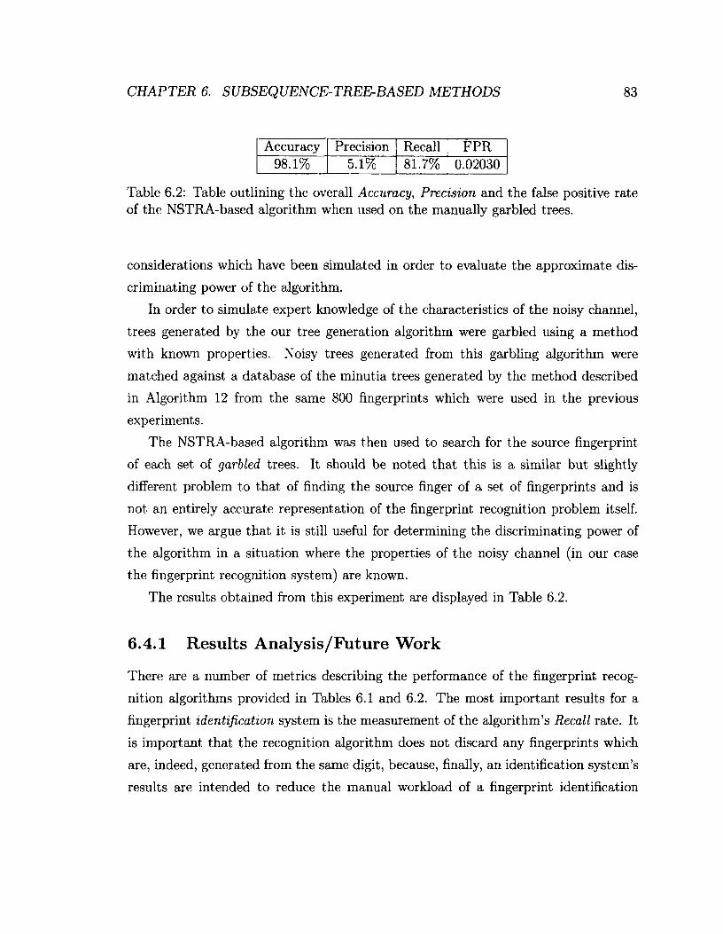
CHAPTER 6. SUBSEQUENCE-TREE-BASED METHODS 83
Accuracy Precision Recall FPR 98.1% 5.1% 81.7% 0.02030
Table 6.2: Table outlining the overall Accuracy, Precision and the false positive rate of the NSTRA-based algorithm when used on the manually garbled trees.
considerations which have been simulated in order to evaluate the approximate dis
criminating power of the algorithm.
In order to simulate expert knowledge of the characteristics of the noisy channel,
trees generated by the our tree generation algorithm were garbled using a method
with known properties. Noisy trees generated from this garbling algorithm were
matched against a database of the minutia trees generated by the method described
in Algorithm 12 from the same 800 fingerprints which were used in the previous
experiments.
The NSTRA-based algorithm was then used to search for the source fingerprint
of each set of garbled trees. It should be noted that this is a similar but slightly
different problem to that of finding the source finger of a set of fingerprints and is
not an entirely accurate representation of the fingerprint recognition problem itself.
However, we argue that it is still useful for determining the discriminating power of
the algorithm in a situation where the properties of the noisy channel (in our case
the fingerprint recognition system) are known.
The results obtained from this experiment are displayed in Table 6.2.
6.4.1 Results Analysis/Future Work
There are a number of metrics describing the performance of the fingerprint recog
nition algorithms provided in Tables 6.1 and 6.2. The most important results for a
fingerprint identification system is the measurement of the algorithm's Recall rate. It
is important that the recognition algorithm does not discard any fingerprints which
are, indeed, generated from the same digit, because, finally, an identification system's
results are intended to reduce the manual workload of a fingerprint identification
CHAPTER 6. SUBSEQ UENCE- TREE-BASED METHODS 84
expert. Accuracy is also important, but this is greatly influenced by the ratio of fin
gerprints corresponding to the probe fingerprint, and the total number of fingerprints
in the database. Since the total number of fingerprints in the database is often far
greater, the difference in Accuracy between different algorithms will appear to be
small. The Precision of the fingerprint recognition algorithm is also important, as it
indicates, in part, how many correct results will be contained within the returned set
of fingerprint matches.
Bozorth's Algorithm performs as reported in [39], with an overall Recall of ap
proximately 74.8% and with a very low false positive rate.
The Hough Transform-based algorithm does not perform particularly well overall,
but it is capable of matching fingerprints of high quality. This is as expected because
it is a relatively simple technique, and large quantities of noise prevent the algo
rithm from performing useful transformations on the minutiae "point sets". During
the tuning process it was noted that the Hough Transform alignment had difficulty
producing a suitable alignment for performing a point-to-point match once a modest
levels of noise was reached. This could explain its poor Recall when challenged with
levels of noise found in the fingerprints in the FVC2000/FVC2002 databases.
The K-plet-based algorithm performs excellently, obtaining an overall Recall of
76.8%. However, it has a low Precision rating of 10.1%, which results in a slightly
larger returned sets of fingerprint matches. Because of the local-scheme nature of the
algorithm, the K-plet-based algorithm has a much higher false positive rates than
either the Bozorth's Algorithm or the Hough Transform-based algorithm.
The NSTRA-based algorithm obtained a Recall rating of 69.6% which is com
parable to the algorithms it was competing with, although the false positive rate
(FPR) was much higher. There are several possible reasons for the high FPR. The
NSTRA-based algorithm is a local-scheme and is thus much more tolerant of dis
tortion and has a much lower discriminating power than a global-scheme algorithm
[1]. Also, as previously mentioned, the NSTRA-based algorithm, as it has currently
been implemented, has not yet fully incorporated the information about the noise in
the fingerprint's channel, which we believe, could be a source of both inaccuracy and
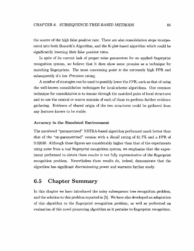
CHAPTER 6. SUBSEQUENCE-TREE-BASED METHODS 85
the source of the high false positive rate. There are also consolidation steps incorpo
rated into both Bozorth's Algorithm, and the K-plet-based algorithm which could be
significantly lowering their false positive rates.
In spite of its current lack of proper noise parameters for an applied fingerprint
recognition system, we believe that it does show some promise as a technique for
matching fingerprints. The most concerning point is the extremely high FPR and
subsequently it's low Precision rating.
A number of strategies can be used to possibly lower the FPR, such as that of using
the well-known consolidation techniques for local-scheme algorithms. One common
technique for consolidation is to iterate through the matched pairs of local structures
and to use the central or source minutia of each of them to perform further evidence
gathering. Evidence of shared origin of the two structures could be gathered from
any features known to be stable.
Accuracy in the Simulated Environment
The simulated "parametrized" NSTRA-based algorithm performed much better than
that of the "un-parametrized" version with a Recall rating of 81.7% and a FPR of
0.02030. Although these figures are considerably higher than that of the experiments
using noise from a real fingerprint recognition system, we emphasize that the exper
iment performed to obtain these results is not fully representative of the fingerprint
recognition problem. Nevertheless these results do, indeed, demonstrate that the
algorithm has significant discriminating power and warrants further study.
6.5 Chapter Summary
In this chapter we have introduced the noisy subsequence tree recognition problem,
and the solution to this problem reported in [5]. We have also developed an adaptation
of this algorithm to the fingerprint recognition problem, as well as performed an
evaluation of this novel pioneering algorithm as it pertains to fingerprint recognition.

Chapter 7
Overall System
In order for the reader to get a better picture of the project that we undertook, it
is important to overview the components of the system developed as part of this
thesis. This will also properly put into perspective the performance of each matching
algorithm, by providing a full and detailed picture of the environment in which the
algorithms were tested.
This chapter overviews the design and development process as well as the major
features of the system developed throughout the course of this study. The major
decisions made throughout the design will also be described and rationalized. The
implementation details are provided for each of the phases described in Chapter 2
(Section 2.6).
An illustration of the various parts of the system, as well as the state of the
data/information on its path through the system is given in Figure 7.1. The light
blue lines represent the flow of data through the system, and the red dotted-lines
represent manual redirection of the data-flow by its human supervisor.
The detailed overview that follows includes the design rationale, the main features
of the system, and the system's components as they pertain to the phases described
in Chapter 2. To illustrate the available interface some typical examples are also
included.
86
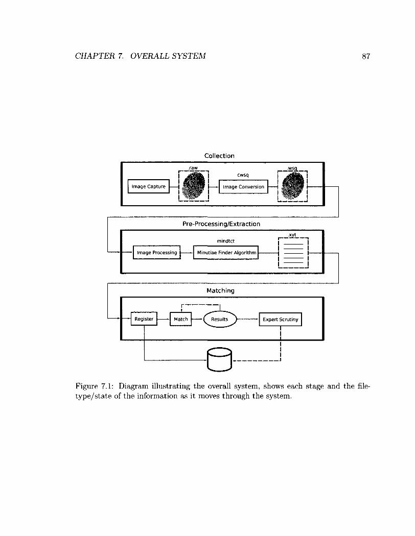
CHAPTER 7. OVERALL SYSTEM 87
Collection
I—— Image Conversion Image Capture
Pre-Processing/Extraction
Image Processing
mindtct ,xyt_
Minutiae Finder Algorithm
Register
Matching
Match Results Expert Scrutiny
T
J
Figure 7.1: Diagram illustrating the overall system, shows each stage and the file-type/state of the information as it moves through the system.
CHAPTER 7. OVERALL SYSTEM 88
7.1 System Features
First of all, it is pertinent to mention that the fingerprint recognition system was
developed keeping in mind specific fingerprint matching algorithms. We emphasize
though that we have incorporated built-in tools for the benchmarking of biometric
matching algorithms, including capabilities for adding noise, adding new algorithms,
and piping the results from one phase to another. In particular:
• Fingerprint matching can be performed with a number of different algorithms
including the Bozorth algorithm, a Hough Transform-based algorithm, a K-plet
representation-based algorithm, and a novel noisy subsequence tree recognition-
based algorithm.
• The system is not limited to the base set of matching algorithms. It is capable
of being easily extended with new techniques. Extensions can be added via
Python's system shell utilities or through the use of the "ctypes" extension
library for linking shared object files.
• Matching sets of prints can be fed from one algorithm to another, permitting
the construction of hierarchical matchers.
• The system components are all scriptable and have easy-to-use APIs.
7.2 Design Process/Rationale
A fingerprint recognition system, whether it is designed for identification, verification,
or both, is rooted in the transformation of RAW1 images collected from a fingerprint
scanner to a matching process between those RAW images. Thus, the ultimate goal
throughout the design of a fingerprint recognition system is to create the data pipeline
from the fingerprint scanning stage to the matching stage.
Although a complete system should have been able to collect fingerprints, it would
be impractical to collect a large enough set of fingerprints for testing when they are
xWhen referring to something as "RAW" (with all capital letters) we are not indicating that it is raw data, but rather information in one of the several existing raw image file formats.
CHAPTER 7. OVERALL SYSTEM 89
easily available elsewhere, and thus the first task was the collection of fingerprints
from existing fingerprint databases. In addition, we set out to obtain, from open
source software, as many of the components of the system as possible so as to not
repeat previously completed public efforts.
With respect to data collection, we were able to obtain access to two fingerprint
databases from the FVC2000 and FVC2002 international fingerprint verification com
petitions. These databases, collectively, included 7,040 individual fingerprint images
from a total of 880 unique digits. Each of these images were stored in the widely used
TIF image format.
Of the open source software components available in the fingerprint recognition
field, the toolkit from the NIST was determined to be the most comprehensive one.
The NIST toolkit had the additional advantage of explicitly not requiring a license.
This NIST fingerprint recognition software toolkit is known as the NIST Biometric
Image Software (NBIS) package. The tools included as part of the NBIS package are
primarily designed for working with RAW, WSQ, and JPEG images. In order to take
advantage of as much of the NBIS package's tools as possible, we needed to be able
to convert between the TIF format of our procured databases of images to formats
supported by the package.
The tool we were most interested in from the NBIS package was the "mindtct" pro
gram used to extract minutiae from fingerprint images. In order to use this program,
we needed the ability to convert our TIF database into the FBI's standard biometric
WSQ image format. Tools for converting, both from and to, RAW and WSQ images
were included with the NBIS package, namely "cwsq" and "dwsq". Although these
were programs for encoding and decoding WSQ images respectively, they were not
immediately usable. In order to utilize the NBIS package with our system we needed
to determine which RAW format the NBIS package supported. A number of different
RAW formats exist for raw image data, of these we determined that the RAW image
format used by the NBIS package was a plain one-dimensional array of bytes which
could be read directly into a c-style string and converted to-and-from various formats
by using tools like the Python Imaging Library. Therefore, we converted the TIF
images into the NBIS package's RAW format, which permitted the use of the "cwsq",

CHAPTER 7. OVERALL SYSTEM 90
"dwsq", and "mindtct" programs.
Once the complete usage of the NBIS package was achieved, much of the image
conversion, image processing, and minutia-extraction phases of the data pipeline in
Figure 7.1 could be constructed.
7.2.1 Fingerprint Library
The completed components necessary for constructing the data pipeline, as outlined
in Chapter 2 (Section 2.6), and illustrated in Figure 7.1, were conglomerated into
a cohesive and consistent wrapper library. In addition, this library contains useful
abstractions and features not provided by its constituent components.
We adopted an object-oriented approach which was centered around an abstrac
tion over all the files and processes that provided the pre-match information about
a fingerprint. The information we refer to here is predominantly that which is used
by various matching algorithms. This also includes the file formats: RAW, WSQ,
TIF, PNG, XYT, and MIN. A fingerprint object was designed for the tracking of a
particular fingerprint's files including its RAW, WSQ, PNG, XYT, and MIN files.
The TIF format was excluded since the fingerprint databases were converted entirely
into the FBI's WSQ format. The resulting fingerprint class is outlined in Figure 7.2.
Fingerprint objects would track the location of each of the files associated with the
individual fingerprints without needing to produce them or load them into memory
until it was absolutely necessary2, as well as being able to take an image of any of
the supported types and producing the rest of the files on-demand.
The primary functions for manipulating the fingerprint objects are the following:
move, match, wsq, xyt, min, image, register. With these functions available, a
developer can move the set of files representing fingerprint data all at once, register
the data in the database, request that a file and its associated data be generated,
or match that fingerprint against another with an existing or new algorithm entered
in "extensions.py". With respect to the components described in Chapter 2 as well
as the components highlighted in Figure 7.1, the fingerprint object handles image
2Although the information, such as minutiae, are extracted lazily (on demand), they can also be loaded from a previous session.
CHAPTER 7. OVERALL SYSTEM 91
Figure 7.2: Diagram of the fingerprint class, showing the main externally-visible fields of the class.
conversion, image processing, minutia-extraction, and to a lesser extent, hides the
complexity of dealing with matching utilities.
A developer should be able to use the library to create a fingerprint matching
system either with the fingerprint matching algorithm provided by the NBIS package
(bozorth3) or by supplying his/her own fingerprint matching algorithm. Extending
the library to include more fingerprint matching algorithms is a matter of using the
"ctypes" extension interface to call C shared object libraries or of running the match
ing utility by passing execution to the system shell, potentially requiring the place
ment of the algorithm on the system's "PATH" variable. Once fingerprint matching
algorithms have been added, using them to match fingerprints would merely involve
identifying the intended algorithm with a string argument to the fingerprint's match
function.
7.2.2 The Piping Mechanism
The ability of the system to pipe results from one algorithm to the other was imple
mented by abstracting the pipe to a linked list of algorithm names. Each name is a
unique string identifier of a fingerprint matching algorithm. Once a user has decided
to perform a piping operation, the results will be passed from one algorithm to the
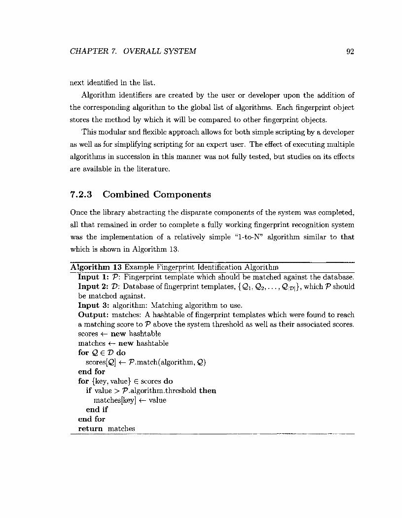
CHAPTER 7. OVERALL SYSTEM 92
next identified in the list.
Algorithm identifiers are created by the user or developer upon the addition of
the corresponding algorithm to the global list of algorithms. Each fingerprint object
stores the method by which it will be compared to other fingerprint objects.
This modular and flexible approach allows for both simple scripting by a developer
as well as for simplifying scripting for an expert user. The effect of executing multiple
algorithms in succession in this manner was not fully tested, but studies on its effects
are available in the literature.
7.2.3 Combined Components
Once the library abstracting the disparate components of the system was completed,
all that remained in order to complete a fully working fingerprint recognition system
was the implementation of a relatively simple "1-to-N" algorithm similar to that
which is shown in Algorithm 13.
Algorithm 13 Example Fingerprint Identification Algorithm Input 1: V: Fingerprint template which should be matched against the database. Input 2: T>: Database of fingerprint templates, {Qi, Q2, • • •, Q\T>\}> which V should be matched against. Input 3: algorithm: Matching algorithm to use. Output: matches: A hashtable of fingerprint templates which were found to reach a matching score to V above the system threshold as well as their associated scores, scores «— new hashtable matches <— new hashtable f o r Q e V d o
scores [Q] •<— P. match (algorithm, Q ) end for for {key, value} G scores do
if value > P.algorithm.threshold then matches [key] «— value
end if end for return matches

CHAPTER 7. OVERALL SYSTEM 93
The schematic strategy shown in Algorithm 13 would work, and would be accept
able in a number of applications. However, there is a more elegant way to accomplish
this same task using the built in piping mechanism shown in Algorithm 14. Both
approaches have their inherent advantages: interacting with the system on an ab
straction level similar to that of Algorithm 13 allows clarity while still being able to
manipulate the matching process in a meaningful way. A common practice specific
to the maintenance of a verification fingerprint matching system would involve the
accommodation for special cases, for example, an unusually low matching score for
particular individuals could be handled by adding a special case to the algorithm.
A simple solution to this example problem would be to lower the matching score
threshold when trying to verify the identity of this specific person. This could be
easily implemented by the user/administrator using the abstraction level shown in
Algorithm 13 without having to deal with the low level details of interacting with the
fingerprint images and extracted minutiae themselves.
Algorithm 14 Example Usage of the Piping Mechanism Input 1: V: Fingerprint template which should be matched against the database. Input 2: T>: Database of fingerprint templates, {Qi, Q2, • • •, Q\v |}5 which V should be matched against. Input 3: algorithms: A single algorithm identifier (string) or a list of algorithm identifiers. Output: matches: A hashtable of matching fingerprint template to match-score pairs. return matching.pipe^, £>, algorithms)
7.3 System Components
This section outlines the system components in the typical fingerprint recognition
system and how they relate to the system that we have developed in this thesis.

CHAPTER 7. OVERALL SYSTEM 94
7.3.1 Raw Data Collection Phase
Raw data collection is an important phase in fingerprint matching systems, and sup
port for it is included as part of the system. However, normal operation of the system
that we have developed implies the use of a pre-existing database since using new raw
data for consecutive tests would not provide enough statistical power to provide in
teresting results.
Raw data collection, when it is used, is accomplished through the use of a scanner.
The fingerprint scanner outputs a RAW image file which can be converted into a WSQ
image with the use of "cwsq" the WSQ compression program described above. Once
the image has been converted into the WSQ format, it is added to the fingerprint
database. An alternative digital fingerprint sensor can be used along with a set of
libraries for interfacing with them. An appropriate open-source library for use with
Linux and fingerprint scanners is the "fprint" fingerprint library, which is used in the
described system.
For the purposes of experimentation, we have not utilized the option of using
actual raw data collection. Rather, we have elected to use the same input WSQ
format images for each test to ensure consistency and to avoid adding additional
variables to the experimentation/test framework.
The data used in the system for the experimental analysis of the performance of
each of the matching algorithms are from the international fingerprint competitions
FVC2000 and FVC2002. In these sets, a collection of 7,040 fingerprints from the
NIST's database were obtained from 880 unique digits.
7.3.2 Data Enhancement Phase
Although it is critical to a production environment, data enhancement is largely
ignored in the developed system. This is partially because of the use of the NBIS
package, which handles minutia-extraction straight from WSQ images, and partially
as a result of the small effect that data-enhancement would have when comparing
the relative performance of different fingerprint matching algorithms against each-
other. In addition, extensive pre-processing of the image may add an unintended and

CHAPTER 7. OVERALL SYSTEM 95
undesirable bias to the performance of a specific algorithm.
The data enhancement that i s present is part of the "mindtct" algorithm obtained
from the NIST. The algorithm takes advantage of contrast adjustment for low contrast
images. Quality mapping is also performed in order to obtain quality-scores for each
extracted minutia so as to aid in the reliability of the respective algorithms.
7.3.3 Feature Extraction Phase and Template Construction
Feature extraction is obviously an essential component of the fingerprint identification
and verification processes. The developed system is no exception, and takes advantage
of the the widely used and open-source "mindtct" algorithm provided in the NBIS
package. The feature extraction is performed by binarizing the enhanced image, using
a fingerprint scanner to perform the actual collection of the minutiae.
The minutiae are extracted and presented along with the angle of their most-
closely associated ridge, the ridge count between them, their most-closely associated
neighbor minutia, and their type. There axe also a number of other qualities of the
minutia which axe stored upon execution of the "mindtct" algorithm but only the ones
listed are used by the implemented algorithms. Two of the several files produced by
the "mindtct" algorithm are used, which are the XYT and MIN files.
Once the system has extracted minutiae, the minutia data is stored in plain text
files formatted with the XYT format used by the NIST minutia matching algorithms,
as well as the MIN format produced by the "mindtct" program. The XYT files store
each minutia as one line in the file, with the Cartesian coordinates and the minutia
angles delimited by spaces. The MIN file contains significantly more information
including ridge counts between nearby minutiae and the type of minutiae.
The templates themselves are actually the fingerprint objects described in Section
7.2.1. The most important information which is required by fingerprint matching al
gorithms resides in the its template which consists of two types of minutia information
files: MIN and XYT.

CHAPTER 7. OVERALL SYSTEM 96
7.3.4 Minutia Matching Phase
Minutia matching is performed using one of the four different techniques developed
and obtained during the research performed in the production of this thesis: Bo-
zorth's algorithm provided by the NIST software package, the Hough Transform elas
tic matching technique, the K-plet graph-based matching technique, and a technique
based on the matching of noisy subsequence trees.
As explained earlier, additional matching techniques can be added. All that is re
quired to accomplish this is a "thin" layer of Python either through the "ctypes" for
eign function interface or simply by a scripted call to the system shell. The matching
algorithms can also be run in parallel by using a wrapper class for the "gnu-parallel"
utility or with Python threads.
Algorithms can use either the XYT or MIN files to obtain minutia information.
Although it is rare for a matching algorithm to work directly with the image itself,
this option is also supported by the fingerprint object's references to the image files
of its associated fingerprint.
Once an algorithm has been produced, it may be added to the system by editing
the "extensions.py" script. The algorithm should take the file-names (one or more of
the XYT, MIN, RAW, or WSQ files) it requires as arguments. The files are passed to
the function through the use of the Fingerprint object and are accessible by named
accessor methods. After the algorithm has an entry in the "extensions.py" file, it
may be called by the command-line interface to the fingerprint identification system,
or may be used in a script which uses the fingerprint systems libraries.
7.4 Usage Examples
In order to illustrate the usage of the available interface to our fingerprint recognition
system as well as to give an overview of the options supported by the interface, some
usage examples are included in this section. The format of the examples follows shell
syntax ("#" indicates a comment) and is also similar to that which is used in "man
pages" where square-brackets indicate the location of a token to be supplied by the
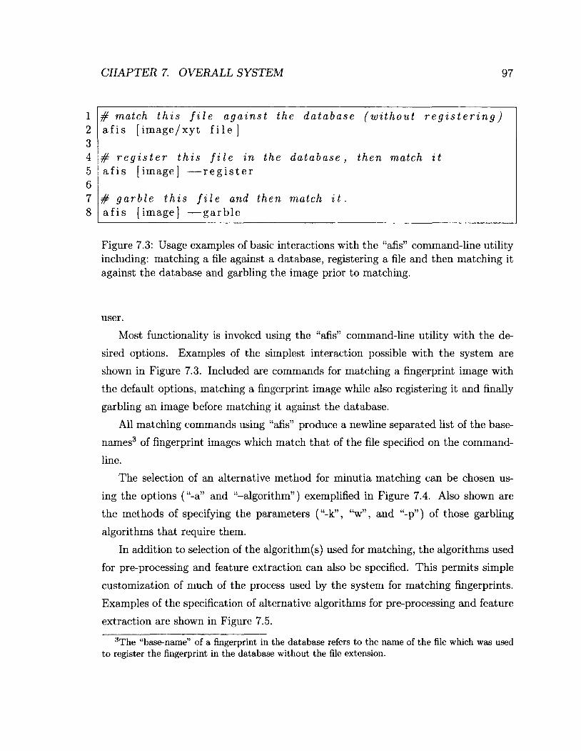
CHAPTER 7. OVERALL SYSTEM 97
1 2 3 4 5 6 7 8
# match this file against the database (without registering) a f i s [ i m a g e / x y t f i l e ]
# r e g i s t e r t h i s f i l e i n t h e d a t a b a s e , t h e n m a t c h i t a f i s [ i m a g e ] — r e g i s t e r
# g a r b l e t h i s f i l e a n d t h e n m a t c h i t . a f i s [ i m a g e ] — g a r b l e
Figure 7.3: Usage examples of basic interactions with the "afis" command-line utility including: matching a file against a database, registering a file and then matching it against the database and garbling the image prior to matching.
user.
Most functionality is invoked using the "afis" command-line utility with the de
sired options. Examples of the simplest interaction possible with the system are
shown in Figure 7.3. Included are commands for matching a fingerprint image with
the default options, matching a fingerprint image while also registering it and finally
garbling an image before matching it against the database.
All matching commands using "afis" produce a newline separated list of the base-
names3 of fingerprint images which match that of the file specified on the command-
line.
The selection of an alternative method for minutia matching can be chosen us
ing the options ("-a" and "-algorithm") exemplified in Figure 7.4. Also shown are
the methods of specifying the parameters ("-k", "w", and "-p") of those garbling
algorithms that require them.
In addition to selection of the algorithm(s) used for matching, the algorithms used
for pre-processing and feature extraction can also be specified. This permits simple
customization of much of the process used by the system for matching fingerprints.
Examples of the specification of alternative algorithms for pre-processing and feature
extraction are shown in Figure 7.5.
3The "base-name" of a fingerprint in the database refers to the name of the file which was used to register the fingerprint in the database without the file extension.

CHAPTER 7. OVERALL SYSTEM 98
1 2 3 4 5 6 7 8 9
10 11 12 13 14 15 16 17
# match this file against the database using a # s p e c i f i c a l g o r i t h m a f i s [ i m a g e / x y t f i l e ] — a [ a l g o r i t h m — s p e c i f i e r ]
# match this file against the database using a # s e r i e s o f c o m m a s e p a r a t e d a l g o r i t h m s a f i s [ i m a g e / x y t f i l e ] \
— a [ a l g o r i t h m — s p e c i f i e r [ , a l g o r i t h m — s p e c i f i e r ] ]
# g a r b l e u s i n g c o n v o l u t i o n w i t h a k e r n e l a f i s [ i m a g e ] — g a r b l e - m ' c o n v o l u t i o n ' \
— k [ b r a c e a n d c o m m a d e l i m i t e d k e r n e l ] \ — w [ w i d t h o f t h e k e r n e l ]
# g a r b l e t h i s f i l e u s i n g ' p i x e L d a m a g e ' w i t h a # p r o b a b i l i t y o f d a m a g e p e r p i x e l o f 1 0 % a f i s [ i m a g e ] — g - m ' p i x e l - d a m a g e ' — p 0 . 1 0
Figure 7.4: Usage examples of several more advanced options of the "afis" utility including: selection of the matching algorithm(s), specifying noise options, specifying options to the garbling algorithms.
1 2 3 4 5
# p e r f o r m p r e — p r o c e s s i n g w i t h a n a l g o r i t h m b e f o r e m a t c h i n g a f i s [ i m a g e ] — p r e — p r o c e s s i n g [ a l g o r i t h m — s p e c i f i e r ]
# match this file against the database using a a f i s [ i m a g e ] — f e a t u r e — e x t r a c t i o n [ a l g o r i t h m — s p e c i f i e r ]
Figure 7.5: Usage examples of supplying different algorithms for pre-processing and feature extraction.

CHAPTER 7. OVERALL SYSTEM 99
7.5 Chapter Summary
Through the course of this chapter we have covered the features of the system, in
cluding a detailed description of the fingerprint library and its implementation and
the piping mechanism which can be used to build hierarchical fingerprint matching
systems. Apart from presenting an example of how the fingerprint library could be
used, we also presented a description of how each component of the system relates to
the original structure of a typical biometric system. Finally we presented a series of
usage examples to illustrate a user's common interactions with the system.

Chapter 8
Conclusions
The aim of the work presented in this thesis was to develop a complete fingerprint
recognition system and to implement and test a novel approach to fingerprint recog
nition. To establish the necessary foundation for addressing this problem, throughout
the course of this thesis, we have included a detailed background of the field of fin
gerprint recognition, an overview of the components which constitute a biometric
system, and a review of several fingerprint matching algorithms of both historical
and technological significance. With this serving as a background, we developed and
evaluated a novel and pioneering NSTRA-based scheme, implemented a prototype
of the NSTRA-based algorithm, and realized a rational specification of the overall
implemented fingerprint recognition system.
8.1 Thesis Summary
In Chapter 2 we described the nature of biometric systems including their charac
teristics, and the trade-offs between various design decisions. We also discussed why
fingerprints are effective biometrics, and the issues related to their distinctiveness.
Finally, we presented, in detail, the process used by fingerprint recognition systems
for matching fingerprints.
In Chapter 3 we covered the image processing aspects involved in fingerprint
recognition. As well, we reviewed algorithms and tools used in typical applications
100
CHAPTER 8. CONCLUSIONS 101
of fingerprint recognition.
In Chapter 4 we discussed challenges faced when storing large fingerprint image
databases and the common approaches to overcoming them. We also discussed the
file formats supported and the tools and libraries used to accomplish the conversion
between different formats. Such aspects of file storage and retrieval are essential
for establishing a fingerprint recognition system that could be successfully integrated
with existing fingerprint libraries.
In Chapter 5 we reviewed several different algorithms of both historical and tech
nological significance, and discussed, in detail, the strategies and algorithms used in
each of the matching techniques included in our system, as well as the challenges
faced during the implementation phase.
In Chapter 6 we outlined the development of our novel and pioneering fingerprint
recognition algorithm based on the NSTRA. We described the reasoning and the
benefits of our approach, as well as the implementation details of the algorithm itself.
We also tested the algorithm's performance relative to that of the other algorithms
specified and implemented in Chapter 5, and provided a measure of the algorithm's
performance in a simulated system.
In Chapter 7 we described the overall features of our fingerprint recognition sys
tem. We covered the various aspects of its design and implementation, and the
rationale behind our design process. We also specified how each component of our
system matches with the abstract model of a biometric system presented in Chapter
2.
8.2 Summary of Contributions
The first contribution of this thesis is a comprehensive library for fingerprint recog
nition. It is a flexible, extensible, and high-level fingerprint recognition library per
mitting the quick assembly of a fingerprint recognition system while hiding the com
plexity of dealing with fingerprint images themselves. The details of the conversion
between appropriate file formats, image pre-processing and minutia-extraction are
all, by default, hidden from the developer. The library also provides parallelism and
CHAPTER 8. CONCLUSIONS 102
the construction of arbitrary hierarchical fingerprint matching algorithms.
Our library used the "fprint" library to interface with fingerprint scanners, and
the "cwsq" and "dwsq" programs to convert between the RAW formats provided
by fingerprint scanners into those used by other fingerprint recognition tools and
packages. Conversion to other supported formats (PNG, JPEG, TIFF) was achieved
through the use of the PIL. Image pre-processing was accomplished through both the
implemented garbling algorithms and through the "mindtct" program.
Our second contribution is a complete fingerprint recognition system created with
our fingerprint recognition library. As with the fingerprint library from which it was
constructed, our fingerprint recognition system is scriptable, extensible and capable
of parallelism.
Our fingerprint recognition system included a set of minutia matching algorithms
comprised of the Hough transform-based algorithm, the K-plet representation-based
algorithm and Bozorth's algorithm. The Hough transform-based algorithm was im
plemented from its specification in [34] and [24], the K-plet representation-based
algorithm was ported from a previous implementation reported in [6] to our system,
and finally, Bozorth's algorithm was obtained from the NBIS package.
As part of the development of this fingerprint recognition system we have im
plemented garbling algorithms based on additive Gaussian noise, convolution with
arbitrary kernels, and "salt-and-pepper" pixel damage. We have also implemented a
mechanism permitting the "piping" of results from one algorithm to another.
Our third contribution was the implementation of a novel and pioneering finger
print recognition algorithm based on a solution (the NSTRA) to the noisy subsequence
tree recognition problem (NSTRP) reported in [5]. We adapted the NSTRA to the
fingerprint recognition problem by encoding minutia information into noise tolerant
trees.
As part of our adaptation of the NSTRA, we also developed a method of encoding
fingerprint minutia information into these noise-tolerant trees. In addition to its use in
the NSTRA-based algorithm, we believe that it could prove effective when combined
with other matching techniques.

CHAPTER 8. CONCLUSIONS 103
8.3 Summary of Conclusions
The developed fingerprint matching system was complete in that it supported match
ing of fingerprint templates produced from fingerprint images. It was capable of
handling several different image types and was capable of matching fingerprints in
a hierarchical manner. While its functionality was complete enough for it to be
considered as a stand-alone fingerprint matching system, its only interface was a
command-line utility. This is certainly acceptable from the standpoint of a developer
or even an "expert" user, but is less desirable from the perspective of a "regular"
user. A graphical user interface is currently being developed for the system which,
we believe, would alleviate this usability problem.
Although our novel fingerprint matching technique is not yet fully complete as
it is missing appropriate noise compensation parameters for a specific application, it
does perform better than expected without data pertaining to the noise applied by its
environment. Although its false positive rate is high, it is still better than a scheme
that randomly discriminates between different fingerprints. The evaluation of the
complete algorithm using artificial noise and a simulated environment demonstrated
that the algorithm has significant discriminating power and certainly warrants further
study. By including noise considerations into the design, we expect improvements to
the performance of the algorithm when used in a real fingerprint recognition system.
In a closed fingerprint verification system, it could be possible to determine an ac
ceptable range of parameters for the algorithm's noise considerations in order to take
advantage of its discriminatory power.
In addition to the developed algorithm, the proposed method of constructing trees
from sets of minutiae may useful when combined with other matching techniques. A
method similar in spirit to that presented in [6] (which was intended for use with
specific graphs) could be adapted to the trees produced by our method. The features
of the trees produced by our method render it useful for fingerprint recognition since
it eliminates the effects of rotation, and dampens the effect of displacement distortion.
CHAPTER 8. CONCLUSIONS 104
8.4 Future Work
The fingerprint recognition system developed as part of this thesis supports the cre
ation of hierarchical matching techniques. One potential area of study could be the
determination of benefits of using hierarchical techniques. This could provide some
value or insight into the weaknesses/strengths of different fingerprint matching tech
niques, and potentially allow the synthesis of more schemes.
There are a number of improvements that could be made to the fingerprint recog
nition system developed in this thesis. The interface, although complete in its support
of the systems features, is rudimentary in the sense that it would only be usable by
a developer or expert user. A graphical user interface (GUI) is in development to
alleviate this issue. The GUI will be web-based and will support remote interaction
with the system.
As previously stated, the most concerning aspect of the NSTRA-based algorithm's
performance is its high FPR. If the cause of the high FPR is a result of discarding some
global spatial relationships, a consolidation step in which more evidence is gathered
and cross-referenced with previous conclusions, could significantly reduce the FPR. It
is also possible that the high FPR is a result of the incomplete state of the algorithm.
In this case, more detailed knowledge of the noise inherent in a fingerprint matching
system would permit increasing the performance of the algorithm.
The algorithm is, as of yet, complete but not perfected. It is our opinion that
the nature of the noise present in fingerprint images must be studied in order to
fully take advantage of the NSTRA-based algorithm's discriminatory power. The
experiments performed on the NSTRA-based algorithm, which utilized artificial noise,
indicated that it possessed a significant level of discriminatory power. It is difficult to
determine exactly where its performance lies when compared to the other algorithms
discussed in this thesis as the artificial noise experiments were performed in a very
different and controlled environment. Nevertheless, we believe that these results
warrant further study. The exact nature of the noise may not be necessary, because
an approximation would, in our opinion, improve the performance of the algorithm
in a complete fingerprint recognition system.

Bibliography
[1] A. K. Jain and D. Maltoni, Handbook of Fingerprint Recognition, Springer-Verlag
New York, Inc., Secaucus, NJ, USA, 2003.
[2] H. Lin, W. Yifei, and A. K. Jain, "Fingerprint Image Enhancement: Algorithm
and Performance Evaluation," IEEE Transactions on Pattern Analysis and Ma
chine Intelligence, vol. 20, no. 8, pp. 777 - 789, Aug 1998.
[3] A. Fareio, A History of Fingerprints, Interpol, Apr 2009.
[4] A. K. Jain, A. Ross, and S. Prabhakar, "An Introduction to Biometric Recog
nition," IEEE Transactions on Circuits and Systems for Video Technology, vol.
14, no. 1, pp. 4 - 20, Jan 2004.
[5] B. J. Oommen and R. K. S. Loke, "On the Pattern Recognition of Noisy Sub
sequence Trees," IEEE Transactions on Pattern Analysis and Machine Intelli
gence, vol. 23, no. 9, pp. 929 - 946, Aug 2001.
[6] N. K. Ratha, R. M. Bolle, V. D. Pandit, and V. Vaish, "Robust Fingerprint
Authentication Using Local Structural Similarity ," in Applications of Computer
Vision, 2000, Fifth IEEE Workshop on., 2000, pp. 29 - 34.
[7] J. L. Wayman, "Technical Testing and Evaluation of Biometric Identification
Devices," in Biometrics, A. K. Jain, R. Bolle, and S. Pankanti, Eds., pp. 345 -
368. Springer US, 2002.
105
BIBLIOGRAPHY 106
[8] Federal Bureau of Investigation, "The Integrated Automated Finger
print Identification System," Online http://www.fbi.gov/about-us/cjis/
fingerprints_biometrics/iafis/iafis, Apr 2011.
[9] B. Burger, D. Fuchs, E. Sprecher, and P. Itin, "The Immigration Delay Dis
ease: Adermatoglyphia-Inherited Absence of Epidermal Ridges," Journal of the
American Academy of Dermatology, vol. 64, no. 5, pp. 974 - 980, May 2011.
[10] S. Pankanti, S. Prabhakar, and A. K. Jain, "On the Individuality of Finger
prints," IEEE Transactions on Pattern Analysis and Machine Intelligence, vol.
24, pp. 1010 - 1025, Aug 2002.
[11] C. Doctorow, "Walt Disney World Fingerprints Visitors," Online http://
boingboing.net/2006/09/01/walt-disney-world-fi.html, Apr 2011.
[12] L. Spadanuta, K. Harmel, and Associated Press, "Disney World Scans Fin
gerprint Details of Park Visitors," Online http://www.boston.com/news/
nation/axticles/2006/09/03/disney_world_scans_fingerprint_details_
of_park_visitors/, Apr 2011.
[13] K. Harmel, "Walt Disney World: The Government's Tomorrowland?," Online
http://newsinitiative.org/story/2006/09/01/walt_disney_world_the_
governments, Apr 2011.
[14] Mythbusters, "Crimes and Myth-Demeanors 2," TV, Beyond Television Pro
ductions, Aug 2006, Season 04, Episode 04, A well reputed fingerprint security
system is put to the test.
[15] S. A. Cole, "Is Fingerprint Identification Valid? Rhetorics of Reliability in
Fingerprint Proponents Discourse," Law & Policy, vol. 28, no. 1, pp. 109 - 135,
2006.
[16] A. K. Jain, S. Prabhakar, and S. Pankanti, "On the Similarity of Identical Twin
Fingerprints," Pattern Recognition, vol. 35, no. 11, pp. 2653 - 2663, Nov 2002.
BIBLIOGRAPHY 107
[17] F. Galton, "Personal Identification and Description," The Journal of the An
thropological Institute of Great Britain and Ireland, vol. 18, pp. 177 - 191, 1889.
[18] W. J. Herschel, "Skin Furrows of the Hand," Nature, vol. 23, no. 578, pp. 76,
Nov 1880.
[19] N. Grew, "The Description and Use of the Pores in the Skin of the Hands and
Feet, by the Learned and Ingenious Nehemiah Grew, M. D. Fellow of the College
of Physicians and of the Royal Society," Philosophical Transactions, vol. 14, no.
155-166, pp. 566 - 567, Jan 1684.
[20] Federal Bureau of Investigation, "Electronic Biometric Transmission Specifica
tion," Criminal Justice Information Services, May 2010.
[21] T. Reed and R. Meier, "Taking Dermatoglyphic Prints. A Self-Instruction Man
ual.," Amer Dermatologlyphic Assoc Newsletter Suppl, pp. 1 - 45, 1990.
[22] H. C. Lee and R. E. Gaensslen, "Advances in Fingerprint Technology," Elsevier
Science, p. 290, 2001.
[23] R. D. Bahuguna and T. Corboline, "Prism Fingerprint Sensor That Uses a
Holographic Optical Element," Applied Optics, vol. 35, no. 26, pp. 5242 - 5245,
Sep 1996.
[24] N. K. Ratha, K. Kara, C. Shaoyun and A. K. Jain, "A Real-Time Matching Sys
tem for Large Fingerprint Databases," IEEE Transactions on Pattern Analysis
and Machine Intelligence, vol. 18, no. 8, pp. 799 - 813, Aug 1996.
[25] S. Chikkerur, A. Cartwright, and V. Govindaraju, "K-Plet and Coupled BFS: A
Graph Based Fingerprint Representation and Matching Algorithm," in Advances
in Biometrics, D. Zhang and A. K. Jain, Eds., vol. 3832, pp. 309 - 315. Springer
Berlin / Heidelberg, 2005.
[26] N. K. Ratha, S. Chen, and A. K. Jain, "Adaptive Flow Orientation-Based
Feature Extraction in Fingerprint Images," Pattern Recognition, vol. 28, no. 11,
pp. 1657 - 1672, Nov 1995.

BIBLIOGRAPHY 108
[27] R. C. Gonzalez and R. E. Woods, Digital Image Processing, Prentice Hall, Upper
Saddle River, NJ, USA, 2nd edition, 2002.
[28] B. M. Mehtre, N, N. Murthy, S. Kapoor, and B. Chatterjee, "Segmentation of
Fingerprint Images Using the Directional Image," Pattern Recognition, vol. 20,
no. 4, pp. 429 - 435, 1987.
[29] A. K. Jain, S. Lin, H. Pankanti, and R. Bolle, "An Identity-Authentication
System Using Fingerprints," Proceedings of the IEEE, vol. 85, no. 9, pp. 1365 -
1388, Sep 1997.
[30] A. K. Jain and H. Lin, "On-Line Fingerprint Verification," in Pattern Recog
nition, 1996., Proceedings of the 13th International Conference on, Aug 1996,
vol. 3, pp. 596 - 600.
[31] A. K. Jain, Y. Chen, and M. Demirkus, "Pores and Ridges: High-Resolution
Fingerprint Matching Using Level 3 Features," IEEE Transactions on Pattern
Analysis and Machine Intelligence, vol. 29, no. 1, pp. 15 - 27, Jan 2007.
[32] C. M. Brislawn, J. N. Bradley, R. J. Onyshczak, and T. Hopper, "FBI Compres
sion Standard for Digitized Fingerprint Images," Spie, vol. 2847, no. 344, pp.
344 - 355, Nov 1996.
[33] T. Hopper, C. Brislawn, and J. Bradley, "WSQ Gray-Scale Fingerprint Image
Compression Specification," IAFIS-IC-0110-V2, vol. 2, Feb 1993.
[34] D. H. Ballard and C. M. Brown, Computer Vision, Prentice-Hall, Englewood
Cliffs, NJ, 1982.
[35] A. K. Hrechak and J. A. McHugh, "Automated Fingerprint Recognition Using
Structural Matching," Pattern Recognition, vol. 23, no. 8, pp. 893 - 904, 1990.
[36] Z. Chen and C. H. Kuo, "A Topology-Based Matching Algorithm for Fingerprint
Authentication," in 25th Annual 1991 IEEE International Carnahan Conference
on Security Technology, 1991. Proceedings., Oct 1991, pp. 84 - 87.

BIBLIOGRAPHY 109
[37] K. C. Fan, C. W. Liu, and Y. K. Wang, "A Randomized Approach with Geo
metric Constraints to Fingerprint Verification," Pattern Recognition, vol. 33, no.
11, pp. 1793- 1803, 2000.
[38] J. T. Tou and R. C. Gonzalez, "Pattern Recognition Principles," Image Rochester
NY., vol. 7, pp. 377, 1974.
[39] C. I. Watson, M. D. Garris, E. Tabassi, C. L. Wilson, R. M. McCabe, S. Janet,
and K. Ko, User's Guide to Export Controlled Distribution of Nist Biometric
Image Software, National Institute of Standards and Technology, Gaithersburg,
MD, USA, Sep 2004.
[40] The National Institute of Standards and Technology, "Nist FAQ," Online http:
//www.nist .gov/itl/iad/ig/slapseg04_faq.cfm, Jan 2011.