Embed Size (px)
Citation preview

A FEASIBILITY STUD OF
USING MICROPROCESSORS FOR
TELEPHONE TUAFFIC MONITORING
by
PI:IZOUZ R.. PIENNIA
Thesis submitted for the Degree of
Master of Philosophy in the Faculty of
Engineering of the University of London
Department of Electrical Engineering
Imperial College of Science and Technology.
London; September 1 97R

0 AB ST.RACT
In order to provide information upon which system planning •
can be based and future growth forecasting can be Wade, measurement
of telephone traffic is necessary. This traffic is primarily composed
of calls originated by subscribers and is, at present, periodically
measured by electromechanical traffic recorders situated at the exchange.
The recent introduction of exchanges employing sophisticated
common control has extended the need for more detailed measurements.
Studies are also needed on the manner of how subscribers use the
services, and to ascertain the influence that the systems• responses
have upon the caller9 s behaviour. Call Detail Analysis (CDA) has been
successfully carried out, using. electronic data loggers and mini-
computers, although on a small scale due to the relatively high cost
of measuring equipment.
Recent advances in microprocessor technology have brought a
low cost and flexible CDA into the realms of possibility.
The work reported in this thesis is an investigation into
the problems and the feasibility of applying microprocessors to tele—
traffic data collection. During the course of the project an Intel
8080 microprocessor system was built and support software developed.
To investigate the problems in teletraffic recording two
of the most commonly used types of telephone exchange were studied.
However, due to the legal restrictions on the tapping of telephone
lines the College internal exchange was used as the model test exchange.
A telephone monitoring programme was developed, using
machine language (Octal format), which can scan up to 96 telephone
lines and collect information from a group of active lines.

The programme and the interface circuit ;•sere tested for
an actual line and the effect of a group of lines was simulated in
order to test the operation of the program applied to multiple
lines. A main—frame computer program was then written to process
the collected data obtained from the microprocessor analyser, so
providing comprehensive printout of information on each call.
3.

To my Father and Mother

5. CONTENTS
P
Chapter 1: Introduction 10
1.1 Microprocessor Architecture 12
1.2 Microprocessor Technology 111
1.3 Telephone Traffic 14
1.3.1 Types of Traffic 15
1.3.2 The Importance of Traffic Recorders 16
Chapter 2: The Design of a. Microprocessor 20
2.1 'Introduction 20
2.2 The Choice of the•Microprocessor 21
2.3. Intel 8080 Microprocessor 23
2.3.1 CPU Signals and their Use 25
2.3.2 Ina - rrupt Structure of the 8080 28
2.4 Hardware Design 29
2.4.1 Interface to the Operator 30
The front panel as seen by the operator 31
(ii) The front panel as seen by the microprocessor 32
2.4.2 The SPU Support Units 33
2.4.3 The Memory Units 34
2.4.4 Interface to the External World 36
2.5 Software Design 36
2.5.1 The-Main Features of the Operating Program 38
2.6 Conclusion 41
Chapter 3: Telephone System Overview 51
3.1 Introduction 51
3.2 Subscriber°s Telephone Instrument 52
3.2.1 Pay—on—Answer Coin—Box Telephones 53
3.3 Common British Post Office Exchanges 55
3.3.1 Strowger System 56
3.3.2 TXhl Crossbar System 57
3.4 Siemens No. 17 Exchange 58
3.4.1 Line Finder Circuit 59
3,4.2 First Selector 60
(i) One ]igit Selection 61
ii) Two Digit Selection 61 (iii) Final Selector 62
3.5 Conclusion 66
(1)

6.
Page
Chapter 4: Telephone Traffic Measurement
4.1 Introduction • 80
4.2 Measurement of Traffic Flow 80
4.2.1 Time—consistent Busy Hour Traffic 81 recording
4.3 Measurement of Grade of Service 82
(i) Overflow meters 82
(ii) Late Choice Call Meters (LOCM) and Late 83 Choice Traffic Unit Meters (LCUM)
(iii Group Occupancy Time Meters 83
(iv) Call Counting Meters 83
4.4 Types of Conventional Traffic Recorders 83
4.4.1 Trunk Traffic Analysis Equipment. 84
• 4.4.2 Traffic Measurement by Computer 87
(i) Operation 87
(ii) Analysis of Traffic Records 88
(iii) Cost Effectiveness of the System 90
4.5 Call Information Logging Equipment (CILE) 90
4.5.1 Technical Description 91
4.5.2 Analysis of Recorded Data 93
4.5.3 Usefulness of the Equipment 93
4.6 Traffic.Engineering by Simulation Methods 94
4.7 Microprocessor—controlled Telephone Traffic 95 Recorders
4.7.1 A Portable Electronic Traffic Recorder 95
4.7.2 A Call Detail Analyser 96
4.8 Conclusions 98
Chapter 5: The Design of an Interface Circuit
5.1 Introduction 103
5.2 Basic Requirements 103
5.3 Effect of Line Conditions on,Dial Pulsing 104
5.3.1 The Effect of a Resistive Load across 105 the Lines
5.3.2 The effect of a Series RC Load across 106 the Line
5.4 Effect-of Contact Bounce 107
5.5 Line Characteristics dūring a Call Setup 108
5.6 Description of the Designed Interface • 110
5.6.1 Performance of the Circuit 1.12
5.7 Multiplexing Arrangements 114
5.7.1 The Overall Interfacing Arrangement 117

7.
Page
Chapter 6: A Program for Teletraffic Data Collection
6.1 Introduction 130
6.2 The Program Structure 130
6.3 Definition of Events. 131
6.4 Method of Data Acquisition 133
6.4.1 The Scan Rate 133 6.4.2 Time Information 134
6.5 Work Scheduling 135
6.6 Definition of Terms 136
6.6.1 Data Storage Structure 137
6.6.2 - Tables 138
6.7 Details of the Teletraffic Monitoring Program 139
6.7.1 On—Line Data Analysis 139
(i) Pre—dialling states 141
(ii) Data validity check 142
(iii)- A method of merging data and time 142 information
(iv) Break pulses on the line 143
(v) A called line 144
(vi) Tone on the line 144
(vii) Answer 148
(viii) Clear. 149
6.7.2 Search for non—registered Active Lines 150
6.8 Particulars of the Program 151
6.9 An Example of the Operation of the Program 152
6.10 Off—Line Translation of Call Details 158
6.11 Experimental Results
159
6.12 An Estimation of the Run—Time of the Teletraffic 161 Monitoring Program
6.12.1 Minimum Analysis Time 162
6.12.2 Typical Analysis Time 163
6.12.3 Overall Program Execution Time 163
Chapter 7: Conclusion and Suggestions for Further Work
7.1 Conclusions 181
7.2 Suggestions for Further Work 185'
7.2.1 A Permanent Storage Medium 186
7.2.2 Further Work on the Results 188

8.
Page
Appendix 1: Flow Charts for Microprocessor Operating 189 Program
Appendix 2: Flow Charts for Modified MCS-80 Kit 197 Monitoring Program
Appendix 3: Strowger and TXKl Exchanges
A3.1 Strowger System 213
A3.2 Crossbar System 218
Appendix 4: Supervisory Tones 232
Appendix 5: Flow Charts of Teletraffic Monitoring Program 236
Appendix 6: Details of the Main—Frame Computer Program 266 for further Processing of the Final Results
Appendix 7: Digidek P.70 Cassette 'Tape Recorder 273
References 275

9. AClNOWLEDGEMt NTS
The work presented in this thesis was carried out under
the supervision of Dr. G.J. Hawkins of the Electrical Engineering
Department, Imperial College. I am grateful to Dr. Hawkins for
his conscientious supervision, encouragement and advice during the
course of this work. I would like to thank him also for the care
and concern he always shows for the general well—being of his
students.
I wish I could express my gratitude for the support and
encouragement I have received from my parents throughout my studies,
The help and technical assistance offered and provided
by the members of staff and my colleagues in the Communication
Laboratories of the Department is very much appreciated.
Finally, my thanks are due to Mrs Shelagh Murdock who
typed the text conscientiously and accurately.

10. CFT/U.PTIR 1
INt ?OMJCTTON
The number of transistors which can be made on a given
area of silicon has undergone a rapid increase in the last fifteen
years. Integrated circuit technology now makes it possible to pack
hundreds of logic elements onto a small silicon wafer. Large Scale
Integration (LSI), as it is called, can compete with those based
upon the logic module families, provided the production quantities
are sufficient to offset the high cost of LSI chip development.
In 1970 Intel Corporation started work on a standard
universal programmable logic element which resulted in the intrōduction
of the first commercial microprocessor Intel 4004 in 1970 (Ref. 10).
Microprocessors provided the means to replace dedicated
logic circuits with a sequence of software instructions known as a
program. The universal nature of the microprocessors leads to huge
production volumes, which is generally required for an economical
LSI production line.
The rapid acceptance of the microprocessors by manufacturers
and designers has been brought about by their versatility and low
cost, which leads to higher production reliability, improved
performance with a lower production time and cost in various
applications. Through LSI utilization it is now possible to embark
on systems where development cost or production time would have
previously made it unfeasible.
One area in which the application of microprocessors is
going to have an impact is telephony. The move towards a complete

software—controlled telephone system has encountered various problems
including the need for a cheap and flexible processing unit which can
be used in order to decentralise the required control system and,
hence, overcome the reliability and security problems.
Active research has been going on in order to explore the
potentials of microprocessors for applications in all areas of
telephony including teletraffic engineering. While most of the
available teletraffic recorders do not meet the expectations of Post
Office teletraffic engineers, the cost of sophisticated electronic
equipment has not justified their wider contemplation.
The work presented in.this thesis is an attempt at
developing a microcomputer system and exploring its application in ' •
the field of teletraffic engineering. A brief summary of the
material in each chapter of the thesis is given below:
The remainder of this chapter gives a brief introduction to
microprocessor architecture and technology. It also introduces the
nature of telephone traffic and the importance of teletraffic
measurement.
In Chapter 2 the development of a microcomputer based
around Intel 8080 microprocessor is described.
Chapter 3 briefly reviews the telephone system in the U.K.
and details the operation of a Siemens No. 17 exchange which was used
as the model exchange for the experimental tests.
Chapter 4 is devoted to a survey of various traffic recorders
and call analysers. The problems involved in traffic data collection
are also discussed.
11.

Chapter 5 is concerned with design considerations involved
in tapping a telephone line for the purpose of teletraffic data
collection. It then continues to describe an interface circuit
developed for the purpose of the experimental work carried out on the
model exchange. Some problems involved in multiplexing of telephone
lines are also considered.
Chapter 6 studies the test results obtained from the model
exchange and describes a program which was developed to collect call
details from the College exchange. It continues with the analysis
of the results and, hence, the performance of the developed micro-
processor—controlled call detail analyser.
Chapter 7 expresses the final conclusions drawn from the
thesis and a few suggestions for possible further work.
Each chapter is supported with diagrams or flow charts
which are accumulated at the end of the chapter. The thesis also
contains several appendices for further support of the material.
1.1 MICROPROCESSOR ARCHITECTURE
A microprocessor is basically a miniaturised one—chip
LSI processing unit typically consisting of an Arithmetic and
Logic Unit (ALU), a set of registers, an instruction decoder, hnd
a timing and control unit (lief. 1). The internal sub—components
are linked together with an internal bus which is usually extended,
through buffers, to the external peripherals. Fig. 1.1 shows the
basic elements of a microprocessor .supported with external memory
and input/output devices.
12.

The ALU consists of a parallel adder and logic circuits
for arithmetic and logic operations to be carried out under the
supervision of control unit.
The registers include an instruction register which stores
the next instruction to be executed, also the program counter which
holds the address of the next instruction.
The timing and control unit maintains the proper sequence
of operation throughout the system by providing synchronised signal
pulses driven from a standard clock. It also responds to external
signals such as an interrupt.
The instruction decoder translates the machine instruction
codes into micro-instructions which are executed by the processor.
A sequence of instructions (a Program) is stored external to the
microprocessor in the memory unit.
The microprocessors often use time multiplexing methods to
transfer information on their bus system at different times. This
reduces the number of pins used in a package, by making a more
efficient use of the available bus; however, the consequence of
resource sharing is the frequent need for auxiliary hardware to
capture the required information.
Microprocessors can appear.on multichip implementation
usually providing richer functions and more flexibility at an
increased cost. The instruction decoder of these systems can be in
the form of an external read only memory chip containing user-defined
micro-instructions resulting in a faster execution time in
specialised applications.-
13.

14.
1.2 MICROPROCESSOR TECNTOLOGY
The first generation of microprocessors, typified by the
Intel 4004 or 8008, used the p-channel MOS technology because of
its availability (Ref. 1). The n-channel MOS technology was used
in the second generation of microprocessors (e.g. Intel 8080,
Motorola M6800) which were also characterised by their large
instructions sets (up to 80 instructions). The new technology also
improved the speed of operation.
The third generation of microprocessors (e.g. Intel 3002)
use sophisticated architecture and bipolar technology which achieve
higher performance at the cost of higher power dissipation and lower
packaging density. The gate propagation delay of many emitter-coupled
logic products is lower than 1 ns compared with 50-100 ns for MOS
products.
The best of MOS and bipolar technologies have been
combined in integrated injection logic (I-L) technology used for
the production of highly sophisticated microprocessors of the fourth
generation (e.g. Ti. SBP 0400). This technology demonstrates speeds
comparable to bipolar TTL with low power dissipation in the region
of that of CMOS (Ref. 11).
1.3 TELEPHONE TRAFFIC
Telephone traffic is primarily composed of the calls
originated by subscribers and is defined as the aggregate of calls
passing over a group of circuits or trunks.

15.
The average nunfroer of simultaneous calls in progress during
a period is known as the traffic flow, or intensity, and is measured
in the unit known as the "Erlang". The unit provides information on
the portion of the specified period "T" for which a circuit is
occupied and the number of calls which originate during a period "t"
where "t" is the average holding time of the calls occurring during
the period T. Traffic flow = A = C t/T. C = No. of calls during period T.
1.3.1 Types of Traffic
The actual number of calls in progress depends on the time
of origin and the duration of each call. The traffic in which a call
can be originated at any instant of time with an "equally likely"_.
probability, is defined as the "pure chance" traffic. In practice the
number of sources from which a call is originated is finite and
therefore the telephone traffic, strictly speaking, cannot be called
a pure chance traffic. However, the proportion of the number of
calls in progress to the number of sources is very small and
consequently the assumption of pure chance traffic for the telephone
system is acceptable in practice. Such assumption allows probability
theory to be applied to the problems of telephone traffic engineering,
yielding a definition for the "grade of service" for a given group
of circuits as the ratio of the traffic lost to the traffic offered
(Ref. 16).
If the traffic on a group of circuits does not, at any time,
differ greatly from the average traffic, then it is said to be
"smooth". This condition applies to high traffic levels from a small
number of subscribers, or at a particular stage where the peaks.of

the traffic have been spread over a number of circuits, The smoother
the traffic the fewer the number of circuits required to deal with a
given volume of traffic at the same grade of service.
1.3.2 The Importance of Traffic Recorders
There are about 20 million telephones in Britain making
about 16,000 million calls per annum. This means that, on average,
a telephone call is made every 2 ms and, in the busiest period of
the day, calls are made at an average rate of one every 0.3 ms, with
up to 1,500,000 conversations taking place at once (Ref. 5).
About 300 million Pounds per annum are spent on trunk,
junction and internal—equipment provision. When the investment of-
such large sums is being decided, small errors in equipment provision
can be very costly. Although some of the assumptions used in
predicting the future needs may not turn out to be perfectly true,
errors must be minimised wherever possible.
In the field of planning, traffic recorders are used
extensively by service and planning staff to ensure that existing
plant is deployed to the best advantage, and that yearly increments
of plant are provided in time and in the right place. This is also of
particular interest to the manufacturers of the equipment, as such
equipment can rarely become available at short notice.
Data about the trunk network traffic is required for
planning future routes, tariffs and plant growth. Forecasting future
requirements is not easy because it involves assessing growth
potential, the effects of changes in tariff policy, and changes in
16.

17.
social structure and so on. A balance between conflicting customer
expectation of good service on the one hand and cheap service on the
other is continuously being sought. Under-provision of equipment
causes congestion, and could lead to the complete collapse of the
telephone system, over-provision of equipment leads to inefficient
use of resources and requires high tariff rates, which mean that many
people do not avail themselves of the facilities and can lead to even
higher tariffs.
Congestion at present is not a critical determinant of
telephone usefulness; however, the congestion component of the
quality of service influences the equipment provisioning policies.
Statistics show that about 3 per cent of call failures are caused by
congestion, giving a loss of about £6 million/annum in revenue, the
bulk of which is in trunk calls. Zero congestion is never economical
and the annual cost of removing congestion from local or trunk calls
does not justify its contemplation. On the other hand, surveys of
customer dissatisfaction with the service suggest that the system
has more congestion than is shown by statistical surveys. Although
there can be many psychological reasons for that, the issue can be
settled by surveying the actual congestion experienced by the
customer.
With modern telephone systems which incorporate such
facilities as "second attempt", other measures of quality are becoming
more salient. Post-Dialling-Delay, for example, is becoming an
important factor during the transition to new generations of exchanges.
The response of individual users to such relatively new experiences
needs to be analysed.

18.
While the conventional traffic measurements are essential,
their scope needs to be widened to cover new areas of traffic studies
required for modern telephony.

6:^a 6157 C4:D e . 417139 690 resz, R' - Osa OW! IMO 6340 it",, arm, WM 1219 tle
External Clock or 0 Control Signal
MICROPROCESSOR
MEMORY
19.
Fig„ 1.1 Microprocessor Architecture Plus
External Support Circuit

20.
CHAPTER 2
THE DESIGN OF A MICRO-CO 4PUTEEZ
2.1 INTRODUCTION
A digital micro-computer is a machine which manipulates
numerical data using a microprocessor as its Central Processing Unit
(CPU), a set of memory devices, Input/Output (I/0) devices, and
interface components (Ref. 1). The prefix micro- to the words computer
and processor should be interpreted in terms of size and cost and not
capabilities.
The microcomputer is called upon to process three tykes of
information - data, status and control. The nature of the data strongly
influences the microcomputers optimum word length. The status
information describes the states of the peripherals and other input/
output devices and can be transferred in either decoded or encoded
form (Ref. 12).
Control information flows in the opposite direction to
status words, from the microcomputer to the peripherals and other
I/O devices. Every microcomputer instruction to I/O devices includes
selection, or routing, of information in the form of an address.
The form of presentation of the information depends upon the type
of the CPU and has a marked effect on the design and the overall
efficiency of the system.
To design a commercial microcomputer system several
points such as cost, size, reliability, flexibility, compatability
with the. other existing systems, the life cycle of the system
(before obsolescence), and the development time (hardware and

software) should be carefully considered. The overall design is a
balance between the customerls requirements and the feasibility of
meeting these requirements.
This chapter describes the steps involved in the development
of a non-commercial general purpose microcomputer system for
university studies and applications. The particular environment in
which the microcomputer was to be used, mainly the university,
relaxed some of the design considerations. For example, the require-
ments for the number of power supplies and power dissipation were not
stringent and also certain familiarity of the potential users with a
typical computer hardware and software could be taken for, granted.
On the other hand, costly support hardware and software to reduce
design and development time were not readily available and the time
factor was often influenced by the cost factor.
9 9 THE CHOICE OF THE MICROPROCESSOR
The choice of the microprocessor is often the most crucial
step in the microprocessor system design procedure. The available
microprocessors should be surveyed and their capabilities should be
weighed against the system requirements. Although the choice of a
particular category of the processors is a relatively straightforward
decision based on the basic requirements, the selection of a
particular microprocessor is often influenced by the previous
experience as well as other considerations (Ref. 13).
A simple program or routine (Benchmark Program) can be used
to compare the performance of different processors in execution time
and memory requirements. But the benchmark program should not be
21.

22.
taken as the absolute proof as a user cannot predict the most
executable codes and whether he will be able to use the instruction
set efficiently.
Hardware benchmarks can also be of considerable use. The
number of I/O ports, the interrupt structure and other special •
functions (such as Direct Memory Access) should receive careful
attention. The availability of the family parts and their computability
with other existing logic circuits (such as TTL) is also important.
One other important item to be considered before the hard-
ware selection is the software support available to the microprocessor.
Among these are assemblers or cross-assemblers or simulators (see
footnote) which can considerably reduce the software development
time and effort. The manufacturers have, unfortunately, been
relatively slow in backing their products with widespread software
support. The development of the college microcomputer did not
benefit from the present (May 1978) available hardware and software
kits on offer by most leading manufacturers.
The choice to be made for the microcomputer design was
narrowed down to the two then most popular microprocessors, i.e.
Motorola M6800 and Intel 8080. The latter was considered to have
some slight execution speed advantages (Ref. 14) over its very
competitive rival. The 8080 was selected so that the previous
experience gained from the already available Intel 8008 could be
The assembler is a program that converts the mnemonics into binary codes ready for execution.
The cross-assembler is an assembler program run on another machine.
The simulator is a program which runs on a host machine program to simulate the action of the target microprocessor.

called upon. The existing 8008 was considered already out of date
and slow in operation. The complexity involved in using its time-
multiplexed 8-bit bus for data and address transfers and its
relatively few input/output ports and its limited stack depth, as
well as other design shortcomings (Refs. 1, 2) wade 8008 highly
inferior to its successor, 8080.
2.3 INTEL 8080 MICROPROCESSOR
The Intel 8080 is an 8-bit n-channel MOS single-chip
microprocessor organised around an internal 8-bit data bus.
Advances in packaging technology following the introduction of the
first microprocessors resulted in a 40-pin package as the standard
for second generation microprocessors (including the 8080). The
large number of pins offered the possibility of using separate
unidirectional address and bi-directional data busses. However,
the economy associated with time-multiplexing (as in 8008 address
presentation) forced the retention of some aspects of this feature
in other generations of microprocessors. Since no data flow can
occur until the target address had been set up , the data bus is
available for the flow of other information (such as status
information) prior to the presentation of the data (Ref. 2).
Fig. 2.1 shows the basic blc-2k design of the architecture
of the 8080. Data transfer between the internal registers and, the
memory (RAM) needs 16 bits of address, 2 bits of op-code and 3 bits
for internal register address. The overall 21 bits of information
would have occupied three bytes of instruction storage, requiring
three memory fetch cycles. This was avoided by using two of the six
23.
24.
accessible internal registers as memory address holders. Therefore
a single instruction can repeatedly refer to a location in the
memory whose address had been pre-loaded into the H-L register pair
(Register-Indirect addressing mode). The fastest way of changing
the pre-loaded address would then be by incrementing the content of
H-L implying the need for sequential storage of the required data.
This has been one of the weak points of 8008 and 8080 microprocessors
(Ref. 2).
The Arithmetic Logic Unit allows logical and arithmetic
transformation of data. A one-byte instruction is not enough to
specify the source register, the operation, and the destination
register. Since these operations are common, a two byte instruction
would have been costly in terms of memory. Therefore, the generality
of the instruction was sacrificed to allow a one byte instruction to
operate only on one register and accumulate the result in the same
register called the "Accumulator".
Condition flags, or status flip-flops, are generally set as
a result of an operation performed on the content of the accumulator.
These flags can be tested by the following instructions to alter the
program flow using "transfer of control" instructions (e.g. JUMP or
CALL instructions).
The processor should be able to record where the transfer
occurred so that a return to the main instruction sequence may be
effected. If the return address was stored in the RAM, the return
instruction would require at least two address bytes as well as the
op-code information. To avoid this sequential order mechanism in
space, the equivalent sequential order in time (known as the order

25.
of occurence) is used in a Last-Tn-First Out stack mechanism
(Refs. 2, 3) .
The number of stored addresses is, then, meaningless until the
stack capacity is exceeded and only the order of occurence has
meaning. The use of a 16-bit stack pointer in the CPU, to refer to
a user-appointed stack region in the RAM, ensures a virtually
unlimited stack capacity.
The flow of the program into the processor can also be
altered using an external interrupt signal. An interrupt instruction
can be jammed into the CPU only during the times when the CPU is
requesting the first byte of a new instruction. Therefore, the last
instruction is always finished before any action is taken to service
an interrupt request.
2.3.1 CPU Signals and their use
The processor does its job by executing a series of
instructions forming a program. An instruction cycle is defined
as the time required to fetch and execute an instruction (Ref. 3).
Every instruction cycle consists of up to five machine cycles which,
in turn, includes between three to five states (T1 to T5).
In order to synchronize the operation of the CPU, a master
clock provides two-phase non-overlapping clock pulses, known as 01
and 02. A complete cycle of the 01 clock is known as a state of a
machine cycle.
The mechanism by which the CPU knows how many states are
needed for each instruction is the feedback shift register, where

26.
the output of each stage is a function of the previous stage and other
following stages.
The 8-bit status information appears on the data bus at the
beginning of each machine cycle where status strobe (SYNC) signal is
given to enable the external latching of the system select bits. The
internally decoded bits divide the total system into five subsystems
(input, output, interrupt, memory, and stack) and can be used to
prepare the appropriate subsystem to receive or transmit the data
during the subsequent states (Fig. 2.2).
Following the address presentation to the system, the 8080
generates a timing signal, Data Bus IN (DBIN), that tells the
selected subsystem to gate the data onto the data bus. Fig. 2.3 shows
a simplified timing waveform during the first machine cycle of an
input instruction cycle (Ref. 3).
A logical combination of the DBIN signal and the appropriate
status bit (or bits) provides a READ signal for the memory, I/O,
and interrupt; subsystems. A similar combination of status word with
the Write Control signal (WR) from the CPU can result in "WRITE"
timing signal for the memory and input/output units.
Each source of the data must, therefore, have two enable
lines, one for the timing pulse and another for the subsystem select
line. Subsystem selection can also be performed. by Memory Mapped
techniques, where one or more of the address bits are used to
select a particular subsystem. This avoids the use of input or
output instructions, and hence improves the execution efficiency, but
at the Expense of a reduced memory capacity.

Apart from the normal states in a machine cycle, a "WAIT"
state can be forced upon the CPU, following the To state, if the
READY signal indicates the need for the prolongation of the processing
cycle. During the "WAIT" state both the address and the data on the
output lines remain stable and the processing cycle will not proceed
Lentil the READY line again goes high. It should be noted that this
is different from the HOLD state during which the processor
relinquishes the control of the address and data busses to allow for
uses such as the Direct Memory Access (DMA).
The functions carried out during a machine cycle is
therefore as follows (Ref. 3):
State T1: Address is placed on the address bus and status word is
put on the data bus.
State T2: READY and HOLD inputs are sampled and the halt instruction
is checked. The Program Counter is incremented if it was
used during the T1 state.
State T: The processor enter=s wait state if it is required either
due to RPY signal or a HALT instruction.
State T3: DBIN or t i3' timing signals are issued for data flow to/from.
the CPU.
27.
States T4 and T5: Internal Processing is carried out ifneeded.
28.
2.3.2 Interrupt Structure of the 8080
In order to enable the microcomputers to communicate with
• the I/O devices, typical systems use pulled I/O, interrupts, direct
memory access, or any combination of these techniques.
When the interrupt technique is used, the I/O device attracts
the microcomputer's attention by activating a control line (INTERRUPT).
In the polled I/O sequence, the microcomputer initiates the transfer
of information in synchronisation with the program. A high priority
I/O, then, cannot override a lower priority port. In the interrupt
system the I/O port, has the initiative and priority interrupt can be
used at all times whenever "nesting" is permitted Ref. 12).
The interrupt system can be of the "polled" or "vector"
type. The former transfers the Program Counter to a common location
where a routine polls status bits of the I/O devices which could have
been arranged in a priority chain formation. The "vector" interrupt,
however, transfers the PC to one of the several possible locations
(eight in the case of 8080) where a specific routine associated to
that particular interrupt can be executed. This is a more efficient
means of using the interrupt facility where a large number of
devices is likely to request the CPU's attention.
The 8080 uses a "vector" type of interrupt request which
is re-clocked by the internal logic of the CPU so.that the last
state of the progressing instruction cycle can be completed. This
logic disables the interrupt system, sets the interrupt acknowledge
bit (INTA) in the status word while resetting the Memory Read bit, and
inhibits the store of the incremented PC so that the address of the
next selected, but not accessed, instruction can be stacked.

29.
The interrupt cycle is otherwise indistinguishable from an
ordinary FETCH cycle that brings in the next instruction. It is the
responsibility of the system designer to use the INTA bit and DBIN
signal. (during the state T3) to generate a signal which removes the
interrupt request and disables MEMORY READ signal so that the user9 s
own interrupt instruction (generally a special one-byte CALL
instruction) can be "jammed" on the data bus (Refs. 3, 2). The
content of the PC is then automatically saved in the stack region of
the RAM (see footnote) and can be used for a return to the interrupted
program.
The priority encoding of the interrupt levels must be
performed externally to the CPU and is discussed later.
HARDWARE DESIGN
The choice of the microprocessor sets the basic require-
ments of the hardware. Among these requirements are the specified
maximum loading of the CPU lines so that the timing constraints
can be met, thus ensuring the correct data transfer in and out of
the CPU. To avoid any compatibility problem between the external
TTL chips and the n-MOS CPU, and ensure adequate design margins, the
manufacturers suggestions on the layout and the useable family
parts were observed wherever applicable. This saved design and
testing time by reducing the possible sources of error.
This region can be separated from the memory region by using the stack subsystem select bit which appears during.the Ti state of every stack operation.

30.
2.4.1 Interface to the Operator
An interface had to be developed to enable man-machine
communication. The foremost consideration was the type of the
language to be used. The choice (see Section 2.5) was between
different formats of machine language programming, mainly binary,-
Octal or hexa-decimal. The Octal format was selected as it avoided
the cumbersome and time-wasting handling of the binary language while
preserving the basic coding format of instructions (two bits of
op-code, three bits of destination register, and three bits of source
register).
Therefore eight push-button keys (0 to 7) and a data/address
select key are provided to enable Octal inputting of the instructions,
Each key entry is translated into a 3-bit binary code, by hardware
logic which is shifted into a predefined RAM location whose address
and content can be displayed on the front panel, again in Octal
format (six Octal digits for higher and lower address bytes with a
further three Octal digits showing the data content of the memory).
A latch mechanism for a continuous display is used for
simplicity of the design. This has the disadvantage ofincreasing the
power consumption and the current requirements of the system
(Maximum of 2 Amps on +5 volt supply).
In order to facilitate program debugging and the control
of the microcomputer, eight functions are provided - to include:
RUN : Runs the program from a predefined location.
STOP : Stops the program and enables the front panel.
31.
•:EXM.FORW. Allows forward examination of the memory locations and •
their control.
EKM.BACK Allows backward stepping through the memory locations
and their content..
Read Internal :Displays the content of the internal registers and. the Registers (RIR)
flags.
Load Address Is used as an extra bit of information to allow the of Single Step (LAD.SSTP) selection between the user-defined and the software-
defined address for single step executions.
S.STP
Is used to execute one instruction at a time (Single Step).
CONTINUE Runs the program from where it was last stopped.
A CLEAR key is also included to clear the display and reset
address input counter (to be discussed later).
(i) The front panel as seen the operator
Fig. 2.4 shows the logic circuit designed to interface the
front panel keys with the microprocessor using two three-state
buffers (one for the keyboard and the other for the control keys).
Three NAND gates (IA, 1B, 2A) are used to translate each
Octal digit into three binary bits representing 3 bits of data or
address according to the position of data/address select key. A
high to low pulse transition at Al or A2 input of the 74121 mono-stable
(Chip no. 3 ) initiates a strobe pulse to the three-state 8212 buffer
(Chip no. 10) which latches the keyboard information and issues an

32.
interrupt request to the processor. The mono-stable time constant is
set to allow for contact bounces to settle before the information is
latched into the buffer.
A similar arrangement is used for the control keys where
a second buffer (chip no. 11) is strobed by an independent mono-stable
(chip no. 4). A flip-flop (chip no. 6) is used to disable the
keyboard mono-stable (chip no. 3) and block the path to Al input of
chip no. 4 whenever one of the main control keys (RUN, CONTINUE and S.STP)
is activated. Therefore the other panel keys are unable to interrupt .
a running program unless the STOP key was first used in a willing
attempt to terminate the program and enable the path of the strobe
pulses to the buffers.
The strobe pulses are also suppressed, for a period
determined by R2 and C2 of a third mono-stable (chip no. 8), in an
attempt to eliminate the effect of contact bounce during the release
period of a key (the contact bounce from the CLEAR key is considered
unimportant).
(ii) The front panel as seen by the microprocessor
The outputs of the input buffers (Fig. 2.4) are coupled to
the data bus of the microprocessor (Fig. 2.5). The use of three
state buffers in the input mode allows for the maximum decoupling of
the input device from the bus when the device is not used.
The interrupt request signal, issued by the input buffer,
enters the priority interrupt control unit (Intel 8214) and its level
of priority is compared with any other simultaneous interrupt request

as well as a software controlled interrupt threshold (which can be
disabled if so desired).
On receipt of a valid interrupt request, the priority
interrupt control unit repeats the request by issuing an active low
pulse of the same width as the ¢2 clock pulse. This pulse is used
to latch a RESTART instruction into another buffer which will then
proceed to force the CPU into an interrupt cycle and put its single
byte CALL instruction on the data bus after the acknowledgement of
the interrupt request (Ref. 3).
In order to input the latched data, the processor enables
the input buffers, under the control of software instructions which
presents the correct port address and a READ timing signal (see
footnote). A special output instruction is used to re-enable the
priority interrupt control unit for further interrupts.
To output the content of the data bus, the output buffers
(chip nos. 12, 13 and 14) are clocked by a WRITE timing signal and an
address select signal (coming from the 8205 one out of eight decoder).
The latched data is fed to a series of 7-segment LED displays via
their appropriate drivers (Ti - 7447).
2.4.2 The CPU support units
The requirements for high-level clock drivers, synchronising
flip-flops, various timing signals. and bi-directional data bus
drivers led to the development of special purpose support chips
for the 8080.
Correct timing signals for I/O READ or WRITE were derived from the status word and WR and DBL signals. The moans to drive these signals is discussed later in this chapter.
33.

The Intel 8224 clock driver provides a 12 V swing clock
pulse and a synchronising latch for the READY and RESET lines. A
status strobe for strobing the status latch is also available.
The Intel 8228 bus controller provides bi-directional
buffering for the 8080 data bus meeting the voltage and current loading
requirements of the CPU. It also contains a latch for capturing
the status bits at the beginning of each cycle. These bits are
then combined with the•DBIN, WR and IIOLDA signals from the CPU to
provide Memory Read (MEMR), Memory Write (1w7), Input/output Read
and Write (TUT, TN), and Interrupt Acknowledge (INTA) signals
(Ref. 3).
The overall arrangement of the CPU support chips is shown
in Fig. 2.6. To improve the fan out capability of the address bus
lines, bus drivers were introduced with three-state output capability
so that DMA can take place if required at a later stage.
2.4.3 The Memory Units
The microcomputer has the theoretical capacity for up to
64 k bytes of memory. For the basic system two kilo bytes of RAM
and one kilo byte of EPROM (Erasable Programmable Read Only Memory)
chips were considered.
Static RAMs were preferred to the more economical dynamic
RAMs since the static MOS memory chips did not require any critical
timing circuits to refresh their content. Eight Intel 8102 A-4
chips are used to provide 1 k bytes of memory of 450 access time
(Ref. 3). The on-chip address decoders are fed from ten address
34.

35.
lines (AO to A9) while the chip enable inputs are connected to one of
the outputs of an Intel 8205 decoder (Fig. 2.7). The delay from the
address set up to chip enable signal is therefore about 18 nsec
'the 8205 output delay).
The write cycle specification of the memory requires stable
address lines for a minimum of 450 ns with the RAM chip being
enabled at least 300 ns before the data is written into the memory
(data is stored in the RAM during low to high transition of the R/W
signal, as shown in Fig. 2.8).
The R/W pulse applied to the chips is derived from the MEMR
signal which has the pulse width of WR signal from the CPU (equal to
one clock cycle). The 8080 specification ensures a stable address,
at least 730 ns prior to the WR signal, with the clock cycle of 500 ns.
The data is also guaranteed to be stable at least 200 ns prior to
and 140 ns after the WR signal. With the chip enable lagging the
stable address by 18 ns, all the timing requirements of the RAM
memory for the write cycle are met without any need for external
hardware. The compatibility of the memory chips with the timing wave-
forms of the 8080 during the READ cycle was also satisfactorily che:eked.
The EPROM memory chip Intel 8708) also has a maximum.
access time of 450 ns and requires a chip select signal to be present
120 ns (worst case) prior to data output. As the byte select occurs
during the FETCH period of the instruction cycle the time allowed for.
the outputting of memory data is from the address set up Lime
(maximum of 200 ns after the first 09 pulse in state T1) to the data
input time during the T~ state. There is therefore more than 450 ns
available to the EPROM in order to output its data.

36.
9.4.4 Tnterfface to the external world
In addition to the front panel extra interface units are
contributed to the microcomputer card racks to allow its operation
with the teletype and CRT. Work is also in progress to link a
cassette tape unit to the system.
2.5 SOFTWARE DESIGN
The software of a computer provides the means for the
explicit control of the computer operation through a step-by-step
sequence of instructions that form a program.
Each microprocessor has been provided with an "instruction
set" in the form of a list of binary machine codes of 8-bits long
for 8-bit microprocessors. The tedious task of writing a program in
this low level language, and the consequent high rate of errors
resulting therefrom, asked for a more efficient representation of the
instruction set.
The assembly language is a basic language in which there is
normally a one to one ratio between the statements in the language
and machine code instructions (Ref. 4). Host computers can be used
as cross-assemblers to eliminate the need, and its associated cost
e.g. in memory requirement), for an independent assembler running on
a microprocessor system.
To facilitate programming and debugging, high-level
languages have been developed. These are instructions which more
nearly approximate ordinary English where each instruction
corresponds to many machine language statements. High-level

languages are effectively waebine-independent and allow for major
changes in the system hardware (including the change of the micro-
processor used) to have a minimal effect on the software. But
generally high-level languages produce a more inefficient program,
in terms of the occupied memory space and the execution time, than
assembly languages. It has been estimated that (Ref. 20) the code
produced by a high-level language occupies about 1.6 times as much
memory and takes 3.5 times as long to execute as an equivalent assembly code program. The ratios should be considered as an
approximate indication of the merits of assembly code since much
depends on the efficiency of the compiler which translates the high-
level statements into machine codes. It should also be argued that
program development and debugging in assembly code takes about three
times as long as high-level language programs (a very strong point
in favour of the use of high-level languages).
The question of the language to be used for the development
of microprocessor software has been a.difficult one to answer. The
hardware cost of producing microcomputers dropped rapidly during the
first few years of microprocessor availability, increasing the gap
between the hardware and software support systems available to the
users.
The problems in obtaining developed software packages and
software support systems and the unavailability of a direct physical
link between the microcomputer and its potential cross-assembler
(a computer) forced the choice of machine language to be used for
software development. To avoid dealing with the binary representation
of the instructions while preserving the structure of the instruction
37.

38.
codes (for easier recall of the instruction codes by the user) it
was decided to have a simple hardware translator to translate Octal
digits into three binary bits. A series of these bits was then
manipulated by suitable programs to produce and store the appropriate
instructions in the appropriate locations.
2.5.1 The Main Features of the Operating Program
One kilo bytes of program instructions were stored in EPROM
to provide software means for program manipulation through the front
panel keys of the microcomputer. Basic sections of the operating
program are detailed in the flowcharts of Appendix (1). The overall
program uses ten RAM locations as the working space for temporary
storage of updated information. These locations are explained below:
Four' locations (called X through X+3) are used to store up
to four instructions which are generated by the operating program in
the ROM. By altering the content of these locations and transfer of
the Program Counter to location X, the operating program can change
its next executable instruction(s) to suit a particular requirement.
To facilitate program debugging i.e. correcting program
errors) means had to be provided whereby the operator could check
the content of each of the six registers and the flag flip-flops.
This is achieved through the Read Internal Register (RTR) program
which is initiated by its corresponding front-panel key. A three-
bit counter (G) is set in the RAM, during the processor RESET period,
to be incremented during the execution of the RIR program, hence
pointing to a different register each time.

A pair of locations (referred to as Memory Pair Y, or MPy)
is also included in the RAM to store the addresses of particular
importance e.g. the address of the next instruction to be executed
if single step key was pressed by the user).
The representation of a byte in the form of three Octal
digits (i.e. 377 as the highest possible number) did not introduce
any problem as the nineth bit was effectively unimportant and was
therefore automatically shifted out of data. However, this method
could not be used in a six Octal digit representation of a 16-bit
address, since it was desired to represent the address by two bytes
of high and low addresses in Octal format. Therefore the processor
had to be provided with the information indicating the intended byte
(this problem would not exist if hexa-decimal format was used). In
order to avoid using a separate key for the byte selection, the
address input program was arranged to interpret the alternating 8
bits (represented by three Octal digits) as higher and lower bytes.
A counter (F) was provided for this purpose which could be reset by
the CLEAR key enabling uninterrupted loading of the address starting
with the most significant two bits of the higher byte.
The two remaining working spaces (called Z and Z+1) are
used as temporary storage of the registers whenever their stacking
is not desired.
The initiation of the RESET routine enables the interrupt
line, sets the stack pointer, and outputs an arbitrary code on the
panel display to inform the user that the machine is ready to
receive instructions. The starting address can then be defined
(using the Address/Data Select key and the 0-7 keyboard) before data
39.

40.
is input. The input address is loaded directly into Ii and L registers
which can be incremented or decremented for consecutive data input
or examination.
To terminate a running program the "STOP" routine is
initiated which displays the content of the PC at the time of stopping
the program. A continuation of the program can then be initiated
immediately after the stoppage or following the examination of the
internal registers (using R7Rt key). The "STOP" routine can also
be called in the program to enable single step execution (S.STP key)
of the whole or part of the remaining instructions before the CONTINUE
key is used to carry on the program execution.
In order to allow the processor to choose between the single
step execution of the instruction shown by the PC or the instruction
selected by the user (through the setting of II and L registers), an
extra routine (LAD.S.STP) has to be initiated by the user prior to
the input of the starting address for single step execution.
Some basic programs have also been included in the E1'ROM
to allow for the use of paper tape for program loading or unloading a 66 iye .
The capabilities of the system have been enhanced by the
addition of a 1 k byte PROM which contains the modified version of a
standard software monitor program to be used via a teletype. The
original version of the program was developed by Intel Corporation
for use in MCS-80 KIT system. This program, however, used hexa-
decimal numbers and had to be modified to enable the use of Octal
numbers in one- or two-byte representation of input/output data.
Details of the facilities provided by the modified program and the
appropriate flowcharts can be found in Appendix (2).

2.6 CONCLUSIONS
The individual hardware and software functions were defined
before the development stage of the microcomputer system. This was
essential since a trade—off between the hardware and software,
although possible, is not always practicable in a developed system.
The design took notice of the possible future expansion of
the system in memory size, and increased I/O and interrupt units.
The processor bus lines were extended to several card racks to
facilitate the addition. of extra modules.
The introduction of various hardware support chips (such as
timers, controllers, etc.) made the hardware design of some micro-
computer boards a fairly standard work using manufacturer2 s
recommendations. This is one of the reasons which has encouraged
some companies to produce ready—made microcomputer modules eliminating
the need for the design of virtually identical items from scratch
Ref. 21).
The choice of hardware components was, however, not
optimum but based on the desire for the simplicity of the design and
computability of the IC chips. As a result of this the hardware
debugging was facilitated but the power consumption and the chip
count of the final system were increased.
Useful all—pirpose monitoring subroutines were included
in the main operating program which provided useful program debugging
means. The initial software development, however, was considerably
prolonged due to the inadequacy of software support systems. Errors
were found long after the program was considered fully debugged.
One particular weak point of the monitoring routines has been the

inability to modify the content of the registers during their
examinations.
The selected programming language Octal representation of
the machine codes) did not introduce unforeseen problems. It is,
however, felt that hexa-decimal representation of the codes would
have made the system more compatible with the increasing software
packages now on offer.
The choice of'the microprocessor was based on the factors
present at the time of the design. By the time that the machine was
ready for operation, its CPU was already superseded by more efficient
processors of the same family. The Zilog Z-80, for example, sounded
a better proposition. The , life cycle of the microprocessors is in
fact one of the problems that many microprocessor users have had to
face. This is expected to improve as the advances in the hardware
technology approaches a saturation point.
ti 2.

r Accumulator
(8)
, _ Accumulator
latch (8)
Temp. reg. (81
Flag flip flops
Instruction register (8)1
Bi -directional data but
Data ous buffer latch
(8 bit) internal data but
(8 bit) internal data but
Multiplexer
Z (El Temp. reg.
C Reg.
Instruction decoder
and machine
cycle encoding
Timing and
control
w (81 Temp reg.
S Reg. D (8)
Reg. H (81
Reg.
E (8) Reg. L (8)
Reg. Register
array
Stack pointer (16)
Program counter (16)
Incrementer/decrementer (16) address latch
Data bus Interrupt Hold Wait
Write control control control control Sync Clocks
WR DBIN INTE INT Hold Hold Wait Sync pt p= Reset • ACK Ready
(HLDAI
. Power supplies
—5-412 V —~ +5 V
r —5 V
- -GND
Address buffer (16)
At5A0 Address bus
Fig. 2.1 Intel 8080 Block Diagram

STACK I/P
DATA
ADDR.
8080 C PU
1 Clock •
STATUS LATCH
J Strobe
0/P INT.
Fig. 2.2 Selection of Subsystems

ADDR. VALID
STATUS • ; DATA WORD VALID
DATA BUS
J1-STATE ,.4 T --- 13
2 5
status word latch
SYNC.
DBIN
Fig. 203
Timing Waveform of 8080 (First Machine Cycle of an Input Instruction)

- •
P•1
4'
221./
46
3 _3k
CO DTD.Da
RuN
3.3K D, STB
S. STP
1K cHLAD. S.s TP
cHIP r F_xAl At
Fig. 2.4
Front Panel Logic Circuit

7 7
/777
7447 11
7447 1111
7447
77.11. 1 9
LE2
1 VT
Rzt2
t +c •
! s b
+5'1' R s
G7 —4
3 4
e — 4 9
—• 11,6
IcK
4 5V t~ c
It 7.I 2 0
' 1 1 I HUJ1
1g
Fig • 2.5 Front Pannel
I/0 . Circuit
1 i R
+5'l rgr e
w d
+5Y
I
Control Keys Digit Switches
Control Pannel

CPU
D.
12 33
3 ~r
Co 3; -
C7 4c CO
r
A7
!T3
1
3
'5 0. I , r '
MCN/1 h'c Li
77Z /774
N
CO 23
ICF I ~s! 5
7
:. cr .t •s
[N-,?
X / . i?
n
cA i v N
6 2 37
4
5
37 :3E 3j 36
,7
Fig® 206
CPU and its Support Chips
Ictr
il//7

1. • -
4 1 •
4 ' ;
ò5 44 I
14 11
RAM RAM RAM RAM RAM RAM
8102-A4
RAM
1 X 1024
VI IL
ITI I
-" •-t t •r.
I
it
EFRO.1
8708 .
•
›,- r=i • ______ cz)
CO
---... 1
. ' I' • • •
• C f-r,
- . . -t- v t ■ . ' • TY - •-•V
...,...... • 4 ,
IL
• -.. i•_— '..t, 4 , . _____ 4-1 . i • - • 4 ' .. •-• • ..., - -- 4 . 4 • • -4. . • --1 " . t t--- - - - —
RAM
A15
cv.,; I
C=I I '
t3 I0 6 3
BUFFER
8216 7 lJ
BUFFER
Mai-DECODER ( 824J 5
ii I a 3 4 5 6
11.51t A 4
Fig. 2.7 Memory Unit

write cycle time 450 ns. Min.
50.
ADDR.
CHIP ENABLE
CE to write time
300 ns. Min.
300 ns. Min.
2Ons min,
DATA IN
300 ns. Min.
data stable
data input into RAM 0 ns. Min.
y data can change
Fig. 2.8 Timing Waveform of memory Write

51. 'CHAFFER 3
TELEPHONE SYSTEM O VIT IEQ^T
3.1 INTRODUCTION
The public telephone system consists essentially of a large
number of single telephones unevenly distributed throughout the
country, each being connected to a switching centre termed a telephone
exchange (Ref. 17).
The process of a call setup, for a local call, is best
illustrated by Fig. 3.1, as is explained in Ref. 5. The caller
initiates the call and signals the required number to the exchange
which then sets up a path to the called number and informs the caller
of the progress in each stage of the call. The path is broken when
either side clears.
There are four basic signalling systems in use in the U.K.,
depending upon the type of exchange to which the line or trunk is
connected (Ref. 5). D.C. loop disconnect pulsing is used to give a
series of breaks in the loop where the number of breaks, their
duration, and the separation between the trains of pulses convey the
necessary information. For audio links over 25 Km long, DC2 signals
are used; this system completely reverses the current feed to signal
digit pulses.
The other two systems are in-band a.c. 'system AC9, which
uses single tone frequency, and signalling system AC11 which employs
multi-frequency tones for dialled digits and single tone signals for
the transmission of other information.

This chapter lo--.ks at the equipment used in setting up a
telephone call and discusses one particular exchange (Siemens No. 17
system) in more detail.
3.2 SUBSCRIBER TELEPHONE INSTRUMENTS
The elementary circuit of connection between two Central
Battery (CB) telephones is shown in Fig. 3.2. The coil and the battery
are situated at the telephone exchange, and while the coil is
particular to the connecting circuit the battery is shared by all the
circuits on the exchange. As the coil has a high impedance to audio
frequency signals, the greater portion of the speech current, generated
at one end will flow through the receiver of the other end. The
subscriber's set in an automatic telephone area should have provision
for dialling, ringing,as well as a more sophisticated transmitter-
receiver circuit. Fig. 3.3 shows.the circuit of a typical subscriber
instrument known as Telephone 332 which was largely in use up to 1955
Ref. 8). The figure shows the 0.1 /IF capacitor across the
transmitter to by-pass .radio-frequency currents. The dial off-normal
springs are arranged to short circuit the transmitter and receiver
circuits to prevent acoustic shocks in the receiver while dialling
continues. The bell tinkling with dial pulses is also similarly
suppressed. The 2 ,LLF capacitor provides a spark quench circuit
in series with the 30 Qresistance.
In 1955 the B.P.O. introduced a new telephone, the 700
type, with a superior performance in transmission and the suppression
of side tones generated in the instrument. A simplified circuit of
telephone 71 6, without a regulator for line resistance compensation,
is given in Fig. 3.4.
52.

53•
The ringing signal ci-rcui-t is formed by the 1000 ohm magneto
bell connected in series with the 1.8 1,1F capacitor (Ref. 7). The
loop calling signal is completed by the micro-switch contacts and
is formed by the contact GS2, the 23 Q winding of the induction
coil, the transmitter and dial pulse springs. The two diodes suppress
any surge voltage when contact D1 closes as dialling starts.
The increased sensitivity of the 700 type telephone allows
it to be used on longer lines than the earlier types. It is, however,
so sensitive on short lines that without modification the loud
reception would cause discomfort to the customer. This point made •
it necessary to provide all telephones with a regulator which
reduced the sensitivity by an amount governed by the value of the
line current. For D.C. current the regulator has the effect of an
additional current dependent resistance, in series with the trans-
mitter, and typically of about 36 ohms for a line current of 76 mA or
10 ohms for 30 mA.
Other types of telephones exist, such as "Trimphone",
"Kcyphone", and modified 700 type phones suitable for shared service
working. The D.C. signalling path of these telephones is basically
the same as the general 700 type; however, their ringing circuitry
may differ slightly.
3.2.1 Pay-On-Answer Coin-Box Telephones
The basic difference between an ordinary telephone and a
coin-box telephone is that the latter is required to provide two
signals. The first signal consists of the normal dial pulses and
the second is a signal from the coin-box to the exchange to indicate .

54.
the value of coins inserted. In addition to the above two, a further
signal is sent from the exchange to the coin box to unlock the coin
slots. The circuit of the coin-box is, therefore, more complex, as can
be seen in Fig. 3.5, where the regulator has been omitted for the
purpose of simplification Ref. 22).
The relay SU is made sensitive to the line voltage reversal
which occurs when the called subscriber answers the call. The
operation of 'SU opens the coin slot while the exchange equipment
disconnects the speech path and returns pay tone to both sides of
the call, allowing 12 seconds for coin insertion. The fully inserted
coin is then checked before the Mask Contact opens in preparation for
coin pulse signalling. These signals consist of the reduction in line
current, at the rate of 4 pulses per second and are caused by the
insertion of the 5 kQ resistance in the line loop. CP-ON contacts
guard the caller from acoustic shocks during the coin pulsing and
prevent any interference with these pulses by other components of
the circuit. The Coin and Fee Checking C.F.C.) equipment in the
exchange detects the signals generated by insertion of coins, and
compares, throughout the duration of the call, the total number of
coin pulses received with the total number of meter pulses proper
to the call at that time.
Coin-box lines terminate to a transformer-type transmission
bridge in the exchange. This bridge permits the use of a high speed
signalling relay and facilitates the sending of tones to either or
both sides of the connection, with or without continuity of the
transmission path. This is illustrated in Fig. 3.6 by the contact
TN which can isolate one side of the connection from the other when

required. It is apparent that the D.C. condition on a coin-box line
during the call setup is different from the conditions which could
exist for an ordinary line. A coin-box line is A.C. coupled to the
exchange selectors, whereas an ordinary telephone line finds its way
directly into the selectors. Therefore it should be noted that some
of the arguments that will be given in later chapters will not be
directly applicable to the coin-box lines.
3.3 TYPES OF COMMON BRITISII POST OFFICE EXCIIANGES
Most of the about 6200 local exchanges of the B.P.O. are of
the non-director type (see footnote) Strowger exchanges. The rest
are of the director type Strowger, cross-bar systems, or reed relay
(TXE2) exchanges (Ref. 19).
The next level in the exchange hierarchy consists of about
370 primary trunk exchanges.(Group Switching Centres) of mainly
Strowger and about 40 cross-bar TXK1 exchanges.
All 27 secondary trunk exchanges as well as 9 tertiary
trunk exchanges are of cross-bar type, known as TXK42 s. In 1976 the
public service of a large reed-relay exchange, called the TXE4
exchange, commenced (Ref. 23). This exchange can act as a combined
group switching centre and local exchange for up to 40,000 lines
and forms one of the bases of the modernisation plan for the British
telephone system.
Detailed description of the exchanges is out of the scope of
this thesis. Therefore only two commonly used B.P.O. exchanges are
A director exchange translates a standard exchange code to the actual code required for a particular route. In a non-director exchange the actual exchange code has to be dialled as there is no register-translator facility.
55•

mentioned in order to compare their operation with that of Siemens
No. 17 exchanges, which will be discussed in detail later in this
chapter.
3.3.1 Strowger System
The Strowger system is one of the more straightforward
systems to understand, and illustrates most of the essential
principles of automatic switching systems in general. About 36 per
cent of all local director exchanges, 46 per cent of local non-
director exchanges operate on Strowger principles.
In the Strowger step-by-step system of automatic switching
the required line is selected by a process of decimal selection.
Dialling signals in the calling subscriberls line actuate a relay
circuit in the selector which in turn controls the movement of the
vipers (Ref. 9).
Fig. 3.7 shows the main parts of the system in the form of
a block diagram and Appendix (3) goes into more detail describing
the operation of each block.
A calling subscriber signals his line circuit to seize a
first selector which would then return dial tone to the caller. If
the attempt fails, due to the unavailability of. first selectors;"
equipment engaged tone is returned.
The pulses generated by dial then extend the calling line
through the group selector switches to the final selector, which has
access to the line circuit of the called party. The final selector
then informs the called subscriber of the incoming call, and the
56.

57.
.link between the two subscribers becomes complete when the call is
answered. On the other hand, busy tone may be returned to the caller
if the called line is engaged.
The distributive control of the step-by-step exchanges,
although simple, is undesirable since the switching equipment is
busied throughout the progress of a call which may take a considerable
time while the caller decides on the next digit to be dialled.
Further, as busy tone is returned to the caller through the final
selector, the intermediate equipment is only released when the caller
clears the call.
3.3.2 TXK1 Crossbar System
The crossbar systems, like Strowger, are space division
systems as different lines are physically separated. The main
advantage of crossbar systems is the use of common control in the
call setup progress. Other advantages are the faster operating speed
of the crossbar switches, their size, and their precious metal
contacts which eliminate microphonic noise often present in Strowger
contacts. A greater reliability also arises, in crossbar systems,
from relay operation replacing mechanisms.
Fig. 3.8 shows the basic operation of the TXK1 crossbar
exchange, which is discussed in more detail in Appendix (3).
Lifting of handset operates relays in the subscriber's
line circuit which signals the corresponding line marker to hold the
selected path through Distributor Switches (DS) into the Line
Transmission Relay Group (LTRG). The seized register then stored
the dialled number and when adequate information on the called

subscriber is stored; the controller finds the line marker associated
with the DS in which the called line is located. Meanwhile the path
between the caller and the register is held through LTRG and hence
the first line marker is free to serve any other line (Ref. 15).
The LTRG returns all the required signals to both parties.
If the called line is free, the DS in the called end of the line
"hunts" for a free path, through Router Switches (RS), into the
appropriate LTRG and the register and the controller are then freed.
The speech path is completed when the called end answers the call.
Therefore, the essential part of the equipment (i.e. •line
markers, 44.40k4olita, and controllers) are busied for a fraction of a
second and the equipment is used efficiently.
. 3 '4 SIEMENS NO. 17 EXCHANGE
The Siemens No. 17 system was taken as the model exchange
for the experiments and tests needed to be carried out. The choice
was obligatory due to the legalities attached to tapping a public
telephone line. The, exchange is being used in the internal
telephone network of Imperial College and therefore is not covered
by legislation concerning the B.P.O.
The Siemens No. 17 system was originally designed in 1933
and modified some years later (Ref. 9). The system is essentially
a marker-controlled uniselector scheme with common control circuits.
The selectors are positioned stage-by-stage under the control of
the calling subscriber's dial. The distinguishing feature of the
S.17 system is the use of a mechanism of large capacity and with an
58.

59.. .
exceptionally high speed of search, This allows the adoption of a:
straightforward stage-by-stage selection scheme without the need for
complicated devices to keep the time of search within the minimum
pause period between digits (normally regarded as 400 ms). The
system has been designed to operate at the standard voltage of 50 V,
with the usual limits (46-52 V). The tones provided in the College
exchange were similar to standard Post Office tones (Appendix 4),
with the exception of the Equipment Engaged Tone which was no
different from the "Busy" tone. The main arrangement of the system
is shown in Fig. 3.9.
3.4.1 Line Finder Circuit
The line finder No. 17 is a 200 outlet high speed Motor-
Uniselector. The Motor-Uniselector, unlike normal uni-selectors,
cannot be stepped directly from dial impulses. It operates when
the start relay associated with its latch magnet is energized and it
stops and mechanically locks itself when its wipers get to the
marked outlet. These wipers move on banks of contacts at a rate of
200 contacts per second. The 200 lines connected to a line finder
are divided into four banks, each of which is associated with a
separate Start Relay.
The operation of the line finder circuit is preceded by
the operation of. LIQ, relay in the subscriber line circuit (Fig. 3.10)
after the initiation of a call (Ref. 24). This engages the final
selector multiple (through P-wire) and marks the line finder multiple.
The Allotter, started by the start relay, searches for a free line
finder together with a free first selector associated with it. The

6o.
allotted line finder. than "hints" for the calling line in the bank
and is stopped by the battery potential through the 550 Q shunt across
the K-relay in Fig. 3.10, which then operates, releasing the LR relay.
The operation of K-relay initiates the release of the associated
control circuit while extending the first selector to the calling
line. Meanwhile, earth is connected to a traffic meter (if fitted)
to register the call. If a call is originated while all line finders
are engaged, the Allotter is halted and the start circuit is closed
down until a line finder becomes available or a time pulse arrives,
force-releasing the Allotter. It should be noted that under this
condition no Equipment Engaged tone is returned to the caller and he
just queues for a free line finder.
Fig. 3.11 simplifies the closed loop d.c. condition of the
line after the initiation of the call and before the caller is
extended to a first selector.
3.14.2 First Selector
The first selector in this system combines the operation of
an ordinary-type first and second selector. Six first selectors
are served by a single control circuit which is coupled to any of the
selectors, via relay contacts, for the period of time required for
completion of the selector operation. The selector gives access to
250 outlets, divided into five banks. One bank is available for
first digit selection, two for second digit and the remaining banks
for first and/or second digit selection. Access to each bank is
given by prepositioning the wipers after the receipt of the
relevant first or second digit (Ref. 25).

Subject to selector and control being free, the allotter
of the associated line finder tests in via the selector P-wire
connection to the battery. Relay A Fig. 3.12) •then operates to the
incoming loop causing relays B and C to operate while holding earth
is returned on the P-wire. The caller receives dial tone which
remains on the line until either C or relay PA operates. There can
be two modes of operation for the first selector (Ref. 25):
(i) One digit selection: Relay A responds to the dialling
impulses stepping the wipers of DA switch accordingly. Relay C
holds during the impulses only to be released after the end of
each digit. Therefore dial tone is not removed until the'end
of the first dialled digit is reached. Then other wipers of. the
DA switch start a search for a free outlet in the group marked
by the dialled digit.
(ii) Two digit selection: In this mode, the search for a
free outlet at the end of the first dialled digit is inhibited
due to special wiring arrangement between DA and DB switches
which operate relay PA, transferring the control to DB switch.
The wipers of this switch step round to mark a group of outlets
at the end of the second digit when a search to locate a free
outlet in that group begins.
A successful marking of a free outlet stops the wipers and
hence terminates the search. H-relay then operates to extend the
line further to the group selector.
Fig. 3.13 simplifies the D.C. condition of the line when
Dial, Busy or. Number Unobtainable tones are superimposed on it..
The latter two tones can be connected Lo the line at any time after
61.

the receipt of the :first digit but not betty eh the final two digits,
as will be seen later.
The appropriate circuit to be discussed, at this point, is
the group selector. However, as its control circuit operation is
very similar to the first selector and its D.C. line condition is
no different from the final selector, only the latter circuit is
examined here.
(iii) Final Selector:
The final selector includes the transmission bridge and
gives access to 200 lines which may consist of individual or P.B.X.
lines if required. Normally, one control circuit serves six such
selectors and the circuit is arranged to control the application of
ringing current to the called; ringing tone, busy tone and N.U.
tone to the caller. The circuit is also capable of force-releasing
the called party within 30 seconds after the caller had cleared.
The called is then treated as a new caller and dial tone is returned.
The 200 lines are divided into four banks of 50 lines,
called W, X, Y and Z as shown in simplified diagram of Fig. 3.14.
The hundreds digit dialled by the caller decides on two of the four
banks, one of which will, eventually, be selected by appropriately
pre-positioned wipers. This use of single-ended wipers to provide
two groups each of 100 is one of the features of the No. 17 system
and is used o concentrate of traffic into a smaller number of
individual. groups. The principle is known as "pairing" and its
objective is achieved by. arranging the selector involved to receive
a momentary discriminatory signal for even or odd hundreds

63.
selection. This arrangement should not be confused with the Post
Office standard pairing system. The latter uses two separate groups
of 100-line penultimate selectors to access a 200-line final selector,
while here only one group is employed (Ref. 9).
The pairing arrangement as well as the control and line
circuit condition for the final stage of a call is shown in Fig. 3.15.
The operation of relay P is conditional upon the battery potential on
the "+" line. P operates for odd hundreds digit changing the
condition of WS switch (Fig. 3.14). Selection of the particular line
required in either 100 is determined by the tens and units digits
dialled. The impulse trains, being recorded by DA and DB switches,
select one of the 50 marking connections. There are four sets of
markers, each capable of marking 50 lines, each pair being associated
with odd or even hundreds digit. DA1 selects one of the two groups
of digits while under control of tens digits. DA2 points to two
digits out of ten possible ones before the units digit move DB
switches to select one out of ten possible choices. Marking of the
required line is then completed.
The control relays (not shown) then operate to close a path
for the selector magnet latch which steps the selector wipers forward
until the marked line (called line) is reached. The 550Q battery
potential on the P-wire of the non-busy called line operates the
T-relay which in turn stops the wipers by cutting the latch magnet
path. This relay does not operate if the P-wire of the called line
is earthed, indicating a busy line.
. Initially the. line loop resistance consists of the 400Q
winding resistance of the P-relay and the 55 Q resistance of the coil,

64.
the line resistance itself, and the two 200 Q resistances of the
A-relay in series with the 35 Q resistance. However, this momentary
situation, shown in Fig. 3.16, changes when.BB-relay operates within
a fraction of a second afw. the A--relay is seized. The 400Q winding of P-relay is thus short circuited, but the relay can hold
if it has been operated by the pairing signal.
The new D.C. condition of the line (Fig. 3.17) persists
while the A-relay receives the dialling impulse train and transfers
them to DA and DB wipers. No tone can be connected to the caller
line until the outcome of called line marking becomes clear. For
caller-not-engaged condition, relay G (not shown transfers the line
from the control circuit A-relay to the selector A-relay where ringing
tone is returned to caller. On the other occasions where the called
party is busy or number is unobtainable, relays LC and PA operate
appropriately to return N.U. or Busy tones from the control to the
caller. It should be mentioned that under any of the above conditions,
the tone is returned on a balanced line with total resistance as shown
in Fig. 3.18.
Concurrent with the ringing tone to the caller, ringing
current is supplied to the free called line which closes its D.C. loop
on answer. This operates the F and D relays which, with J relay,
previously operated, completesthe speech path via the transmission
bridge. The control circuit is then released, leaving the called
circuit under the control of the D-relay while the A-relay holds the
calling line.
,Fibres 3.19 and 3.20 show the D.C. condition on the final
stages of the call. setup. The marking earth potential of the P—wire .
65.
operates the K-relay in the called subscriber's line circuit and
K relay contacts remove the line potential. Ringing current is then
supplied to the called line and the polarity of the line is reversed.
It is worth noting that the called line potential, rather than the
caller line potential, reverses its polarity when a call is answered.
(The opposite of this condition happens under the P.O. Strowger
exchanges.) Therefore the D.C. condition of the caller line remains
unaffected from the time ringing tone is supplied up to the end of
the call.
Finally, to complete the description of the exchange operation
the "Right-of :Way" function has to be mentioned. An executive calling
an engaged line can obtain "Right-of-Way" by a brief operation of the
special push button on his telephone instrument upon receipt of Busy
Tone. This results in the completion of a connection to the engaged
line, but to allow his presence to be known to the other parties,
Warn Tone is connected to the lines at low level. The exclusive access
to the called extension can then be arranged when both parties of the
existing connection clear; upon so doing, the wanted extension is
rung and the connection is completed as for a norma]. call. The
executive signal to the control circuit is by putting an earth on the
negative line, whereby relay RSA Fig. 3.15) operates via the 200
resistance of the control A-relay. A series of relays then operate
to form a three-way speech path. As this feature of the system has a
rare use, it was not explored any further, neither was any attempt
made to make provision to study its occurrence in the exchange.

66.
3.5 CONCLUSION
The overall telephone system consists of subscriber sets,
links to the exchange, interface between the subscriber and the
exchange, and the switching network of the exchange with the
appropriate control arrangement.
The need to interwork with the other public telephone systems
has kept, in general, the principles of signalling and the basic
design of the elements in the subscriberls loop unchanged. The
crossbar exchange took advantage of the fast operating speed of
crossbar switches and introduced an efficient register control. system.
The Siemens No. 17 system has a switching mechanism similar
to the Strowger type of exchange while it uses the common control
feature of more contemporary crossbar systems. Despite their different
control concepts, the Strowger and the Siemens No. 17 exchanges make
use of similar elements in their subscribers? line loops.
The operation of College internal exchange is summarized
in Table 3.1.

TABLE 3.1
POSSIBLE rrnAl\JSrrIONS PHON ONE STATE filO ANO'nTF.B DUlinrG A CALL SE'r UP
Dra,m for College 'phone ,·lith some possible events in case of normal Public Exchange
Ul <l>
<l> rf}
~ ~ bD r-! H ---. 0 0 ~ CH~ 0 N 0 E-i 'r-l Ul -i-J tt: \I: +'r-! <l> 0 ~
~r-! r-! rn r-! +> Q)' Q)O r-! CH .;tl ro ro cOr-! r-cl ro ~: r-l ~o CH 'M +> 'M 'r-i~ ~A <l> <l> 0..:::1' 0 A U)A A I Z':.fJ. E-i '-"
Off Hook ~ J V % -*-1
Dial Tone ~ J *2
start Dialling -1<-3 ~ J
Dial Pulses ~ V
End of Dial I ~ J J Pulses *4- *5
Next Selector ~ *2
Tone (1100 Hz) . ~ Answer - J
*'6 ~-
Clear Down J. (On Hook) *''7
*" 1 Equipment engaged tone for no available uniselector. 2 Possible to get NU tone if dialling does not follow after
certain time(not in the college exchange) 3 If dial is not fully rotated to produce any dial pulse,
dial tone is returned. 4 Can be after the first digit or after the second digit. 5 Busy,EQ.ENG.,Ringing,or NU tones are possible.
H CI)
"-..... Ul ~.
~
I
~ ~
6 !msltler: is followed by pay-tone in case of t Pay-on-Answer 'phones. 7 Off-Hook condition can imply that Ringing current is to follo\'l.
H ro ~ CI) .....
',--l 0 OA
I
I
I
V
I
I
/
I
~

68.
Start of cat
Ca11- u0
Proc 3-to-5end First
5~ di it Third digit fou~ d
,,,d to set'd
First do
digit Third di if
Fourth diyR
Called' lcrmirtiM-free start of ring ng tQ11e)
of rirx).ng tone) Call -answered (cessation
r Call-answered
Alort- tonnirtal
Cat- answered _~--
Calling terminal Local exchange
Call ended
Local exchange Called terminal
Fig. 3.1
Signal Diagram for a Call Between Two Exchanges
(1 ef:5)
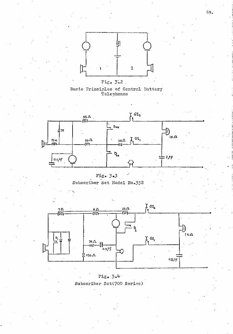
Fig. .2
Basic Principles of Central Battery Telephones
Fig. 3.3 ' Subscriber Set Model No.332
Fig, 3.
Subscriber Set(700 Series)
69.
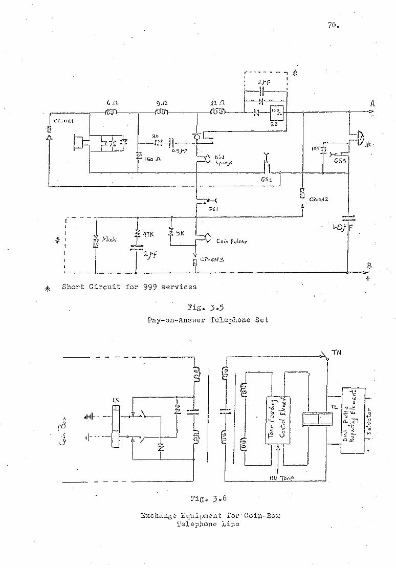
70.
?i'F
,VO
su
39
0 VT 4— 150 .0. -- 'Y Sr..n:ji
Cs 2.
4, Short Circuit for 999 services
Fig. 3.5 Pay-on-Answer Telephone Set
tlU Too
Fig. 3.6
Exchange Equipment Loy Coin-Box Telephone Line

' /0 Waa
L
Fl S
0 f 13) DS
(/I'QI *J f v~
• /T"1 K~l
magags dazs-Rq-dal.s ;o rm.z2t j haoTS
°STJ
•

ROUTER SWITCH
t t
LIRE MARKER
DS
• 1
LM Fig.3.8
TX10 Crossbar Systen

J7
rtn
ma;sgs L ~ • oi1 • suemei s
Jo quaaaSuu.z.Iu ozsug 6°C •h::

TO N:F.TER TERM,WAL:
SLOCK •
TO ■- LINE FINDER
MULTIPLE
l'^' 0 700 7 1R SUBSCRIBER
I
TO FINAL
SE LECTOR MULTIPLE p
TO START
RELAY <3
LR1
Fig. 3.10 Line Circuit of Seimens No.17 Exchange
_ RL
77O0 -o- f — 50 V
Fig. 3.11 Line Condition at Off-Hook and Before 1st Selector is
Seized
: Total Resistance of the Subscriber Telephone Set
RL : Line Resistance DoN ; Dial-Off-iiormal Contacts
Rs ON

J
L3usiTone NU Tone plat Tone
4-
P
A 57Q
'72, Di? r. D3
•
To Mark QaiL is
DB •
Fig, 3.12
First Selector (Seimens No.17)
— j 200
11 LC, C.
DA ~B
P?3
C2 fc 500

sub.line or trunk
VIS
Fig, 3."1k Simplified Diagram of the Four Banks of a 200 Outlet Final Selector in Seiniens
No.17 System
76.
20o,
501"
ZOO
Fig. 3013 Line Condition When Dial,Busy,and NU tones are Received.

P
1 P- kid
- (40,47,1) I.4
NU-7Zne
LC
Fig. 3.15
Final Selector (Seiniens No.17)
Q ij
3 -
,
A D 1150 1'6c. I 6-4
(sccze..-rYi- J.
.... \ow.. 114/.■ —.4. -1-
• F -T, 4 tIcy 2
Uri i 2 G4' . ...
---. F • , vii,,,.) f-‘ t
BB -1-., I:- 4ne , .• c...=

400 35 a'~ v
RL PkN
Fig. 3.16 Initial Line Loop Resistance When a Group or a Final Sel-ector is Seized.
35 400 5o;T
3\
~ :1`$ 1
35 N
78.
Fig. 3.17 Line Loop Resistance
(Steady Condition)
RL 250 Soy" ,n
L v
1 I RL 250
t\A)
Fig. 3„18 Balanced Line Loop
Resistance
Rs; Resistance of the Telephone Set RL: Line Resistance

300 „:„, y
~, .. OPerfft!tt
til
1K
79.
K _ Cferated
"tes i
2co f) RL
Fig. 3.19
A Called Line when Receiving
Ringing Current
i
I(
• I G' 25o 250 r1
5o 11 250 ~.
Fig. 3.20 Line Cordition(d.c)When
a Call is Answered

80.
CHAPTER 4
TELEPHONE TItAFFIC IEA.SUR.EMENT
4.1 INTRODUCTION
It is now generally realized that an accurate knowledge of
the traffic flowing in the network is vital for the proper admin-
istration and economic control of any telephone system. In this
chapter, the means of recording the traffic as commonly used by the
British Post Office is discussed.
4.2 MEASUREMENT OF TRAFFIC FLOW
With the aid of traffic recorders, extensive traffic
measurement can be made to obtain estimates of the traffic carried
by each group of circuits in an exchange. The flow of the telephone
traffic changes by the hour of the day. There is usually a period of
at least an hour during which the fluctuations of traffic flow are
minimum around a value. The traffic is then said to be in statistical
equilibrium (Ref. 34), which means that the probability of finding
any number of simultaneous calls is independent of the time when the
system is examined, provided the time is within the equilibrium
period.
The period of one hour during which the statistical
equilibrium exists for .the maximum traffic flow is known as the busy
hour and is used as a measure of the traffic flow. The individual
circuit groups may have different busy hours which do not necessarily
correspond with the observed busy period for the exchange as a whole.
Therefore, several busy—hour measurements on different days of the
week and even for different months, may be required before the
maximum traffic is recognized.
In practice, information about the traffic flow is obtained
either in terms of the total number of calls during the busy hour and
their average duration, or of the average number of simultaneous calls
in progress during the hour. This can be done by visual observation
of the number of engaged switches or circuits in a group, by
manual testing of each circuit in the group, or by automatic
recording on the meters (Ref. 44).
The procedure adopted by the B.P.O. for automatic traffic
recording was, for many years, the Post-Selected Busy-Ilour Traffic
Recording. Tests were normally made once every 30 seconds over one
and a half hour period with the meter readings taken at half hour
intervals. The busy hour was then taken as the two consecutive half
hour periods during which the number of engaged conditions recorded
was the greatest (Ref. 44). While this method had the advantage of
encompassing the true busy hour, even if this varied from day to day,
it tended to over-estimate the traffic level. It also required a
large amount of meter-reading, which was undesirable (Ref. 31).
4.2.1 Time-Consistent Busy-IIour Traffic Recording-
This method superseded the Post--Selected Busy-flour Traffic
Recording method, and it has been employed by the B.P.O. since 1969
(Ref. 44)
Briefly, recording is normally done over a selected one hour
period each day from Monday to Friday, under control of a time switch
and a cycle counter. The equipment is switched on automatically at a
81.

82.
-predetermined time each day and recording is terminated after 20 scans
of 3—minute cycles, on long—holding—time equipment,. or 200 scans;of
18—second cycles on short—holding—time equipment. The average
time—consistent busy hour traffic can then be obtained, at the end
of the week, by subtraction of the initial and final meter readings
and division by 100 or 1000 for 20 scans and 200 scans respectively.
This method allows more frequent traffic records to be made
from simultaneous recording of both short and long holding equipment,
and avoids the labour in connecting and reconnecting the equipment
)ge meters. As a result of this system,A.recording time is also
substantially reduced and the elaborate processing of the meter
readings is avoided.
4.3 MEASUREMENT OF GRADE OF SERVICE
In automatic exchanges meters, in addition to the automatic
traffic recorders, are provided in order to keep a continuous check
on the grade of service given on the various groups of circuits.
The main types of these meters (Refs. 44, 9) are:
(i) Overflow meters: An overflow meter. is connected so that
it records the number of times that calls occur when all the circuits
in the group are engaged. The meter is operated when the wipers of
a selector, unable to find a free outlet, pass to the 11th outlet.
and reniain there until the selector is released after a maximum of
15 seconds. A second selector cannot operate the meter while it
remains operated by the first selector, therefore further events
remain unnoticed. However, if the total number of overflow calls
is small, the resultant error can be neglected.

83.
(ii) Late Choice Call Meters (LCC,) and Late Choice Traffic
Unit Meters (LCUM): These meters. are used in conditions where the
overflow traffic cannot be measured due to the continuous hunting
action of the switches. The LCCM is connected usually to the last
circuit and records the number of times this circuit is seized. A
contact of the LCCA completes a circuit for the LCUM which records
the cumulative time that the circuit is in use, by being stepped
once every 30 seconds. Therefore:
LCUM reading The amount of time the unit was fully occupied during 120 — one hour i.e. the traffic in Erlangs)
(iii) Group Occupancy Time Meters: These meters are used to
record the cumulative time, usually in 1 sec. or 2 sec. intervals,
during which all circuits in a group are busy. This time, when
converted to hours, is numerically equal to the grade of service.
(iv) Call Counting Meters: These meters are connected to certain
types of equipment, such as senders, which have a fixed performance
time. The meter operates once for each complete call, hence the
product of the meter reading in one hour and the operation time of
the equipment gives the traffic carried.
4.4 TYPES OF CONVENTIONAL TIh&i+'1"IC RECORDERS
In Stroti er exchanges access to traffic recording points
is via uniselectors. These points are usually the private wires,
although separate traffic recording leads are provided in some cases.
The busy condition is indicated by the presence of an earth and each
uniselector, using 49 of its 50 outlets, can scan 147 access points
with three sets of wipers.

Tn TYK1 crossbar system, access to the traffic recording
leads is via the crossbar switches which cater for a maximum of
1200 leads to long-holding-time (1.h.t.) equipment and a maximum of
40 usable leads to short-holding-time (s.h.t.) equipment and 10
leads to very-short-holding-time (v.s.h.t.) equipment, such as markers
and router controls. The above groups of equipment are scanned
at 20 sec., 2 sec. and 200 ms intervals. A feature of the TAIK1
recorder, not previously included in traffic recorders used by the
B.P.O., is the ability to measure delay in receiving dialling tone.
This facility is used in some countries where exchanges are deliber-
ately designed to handle a given quantity of traffic with a specified
delay. This delay is then used to assess the need for equipment
extension (Ref. 31).
4.4 .1 Trunk Traffic Analysis Equipment
This equipment was developed in the mid 19607 s for the
random sampling of trunk traffic in a.Group Switching Centre (G.S.C.).
The equipment is connected toAregister-access_relay set, as shown
in Fig. 4.1, and records such information as the dialled digits and
meter pulses which are punched onto a paper tape for subsequent
computer processing.'
A maximum of 3000register-access-relay sets can be
connected to the analysis equipment which can only monitor one out of
every n incoming calls. Each register-access-relay set has a count
wire on which a 50 ms earth pulse is sent to a "pulse separator" unit
shared by 100 other count wires. The pulse separator produces a 24s
pulse to a counter which is set to operate the NN relay when a count
• of n is reached. The contact of the NN relay then prepares the
84.
circuit for the operation of the next A relay which receives a 50 ms
earth pulse.
The operation of this A-relay initiates the hunting action
of a motor uniselector to find its marked output. The signals on
the P and M wires are detected by high impedance relays before being
stored and switched by orthodox electromechanical circuits, into the
perforator control to operate the perforator magnets. The dial
pulses are stored on a uniselector until an inter-digital pause
indicates that a complete digit has arrived. This digit is punched
on the tape, and the uniselector homes (Ref. 30).
The paper tape contains information on the date and the
time of the day and details of the observed call, such as off-hook,
dialled digits, answer, meter units, and on-hook events; also, the
value of n when the record was made. A time character is punched on
the tape every 5 minutes throughout each 24 hours. During the
monitoring the call--timer suppliestime pulses so that the time, in
seconds, from the beginning of the call to each event can be.
pinched on the tape.
The design of the equipment had to take into account some
practical aspects of taking the samples. As the holding times of
calls vary considerably, it is possible that during the observation
of the IC.nth call, the (K+1).nth call arrives, so causing the
termination of the previous observation before the completion of the
call. The value of n can be chosen in order to reduce the above
possibil isy.
The probability of a call lasting longer than time t is
e-t/Z , according to negative exponential d:i.stri',~ution of random
85.

arrivals (lief. 36), where T. is the average holding time of calls.
This probability is less than 0.01 for a t/i ratio of 5. Therefore,
if n was chosen so that the time taken to count from zero to n is
five times the average holding time for all calls, then less than
1 per cent of the observations will be forcibly terminated. Assuming
that C calls arrive per hour, then the time taken for n calls to
arrive is n/C, which should be equal to 5T. It follows that the
value for n should be equal to 5A, where A = CZ is the total traffic
flow.
The data on the paper tape is fed to an off-line computer
which is programmed to calculate particulars of the sampled calls
such as the average holding time, the number of calls that failed,
and the meter pulse rate for the particular code dialled.
The trunk traffic analysis equipment provides valuable
information on the traffic 'flow in the network. Its operation is not
restricted to the busy hour and, therefore, any shift in the busy
period can be detected. It reduces the labour involved in processing
and scrutinizing the records and collects useful details on the
particulars of the calls. However, it is expensive in hardware and
Slow in operation. Its cost-effectiveness could be greatly improved
if more than one call at a time could be monitored, employing a
scanning process. Even then, the prospect-of a large number of
traffic recorders producing an unmanageable quantity of paper tapes
could limit the utilization of the equipment.
The inclusion of a processor to give a traffic recorder
that provided its own analysis printout was considered unfeasible
at the time the Trunk Traffic Analyser Equipment was introduced.
86.

87.
4.4.2 Traffic Measurement by Computer
In 1969 the B.P.O. decided to investigate the possibility
of the control of traffic recorders. over a data link by a dedicated
computer with one computer controlling all the recorders in an area
(Ref. 35). This was made necessary by the high cost of manually
recording and calculating telephone traffic.
The most promising system was considered to be the one which
aims for a minimum of equipment to be located at each exchange and for
a suitable group of exchanges to be connected by data links to a
centralised computer which would control the local equipment and
receive and process the traffic, data.
All traffic recorders working on a scanning principle
consist basically of two parts: the control section and the access
equipment. Much of the cost of a traffic recorder is in access
equipment, therefore the access uniselectors of the Strowger traffic
recorders are retained and used, after being slightly modified, to
interface the control system with the subscriber's P—wire (Ref. 32).
(i) Operation:
Fig. 4.2 shows the general configuration of the computer
and a traffic recorder. The access uniselectors are grouped into
blocks of three, with the capacity of 441 access points. Each
block is identified by a 9—bit code which is wired to the home
contacts of the nine uniselectors forming one of the thirty possible
blocks.
The operation of each traffic recorder in each exchange is
independently controlled by the computer. Start—up is initiated for

a particular traffic recorder 30 minutes before commencement of the
busy hour when the wipers of the uniselectors are automatically set
to home-positions. At the commencement of the busy hour a block
identifier code, received from the computer, is decoded in order to
select the required block.
The scanner-sender reads simultaneously the conditions on
the nine access leads into its store and assembles a character
consisting of the nine bit conditions on the wipers and a parity bit.
This character is then sent at a rate of 200 bits/sec. to the computer
which expects the first and the last characters to be the block
identifier code. The complete scan cycle is repeated 20 times during
a recording hour. Any access block can be scanned with a periodicity
ranging from 3 minutes to 6 seconds by repetition of its code within
the block list in the computer..
At the end zif the recording time, information on faulty
lines is transmitted by the computer to the exchange maintenance staff
who then send confirmation of the fault to the computer so that false
results CQK be deducted from the data.
(ii) Analysis of traffic records:
The computer has in its store several programs to meet the
needs of traffic recording and analysis. Data received from the
traffic recorders are stored on the compnter2 s disc and magnetic
tape storage to produce a single :lays record, a weeks record, or
a 4 week7 s record of the measured traffic. Some of the features
(Ref. 35) of the analysis program are:
88.

89...
(a) Inspection of the records of all access points and a
comparison with the access point look-up file to check that no
access circuit has been engaged all the week and that no
unallocated point has carried traffic.
(b) The measured traffic is compared with the critical
traffic for each circuit group and overload indication is.given
when appropriate.
(c) Special records are kept in the master file for
later reference.
(d) The traffic of all groups entering and leaving particular
switching stages are summed and percentage differences in the
lost or gained traffic are given for the relevant switching stage.
(e) Call destination analysis is performed using the data
collected by Call Failure Detection Equipment (C1DE) which
continuously samples a maximum of 120 calls arriving at the first
switching stage within an hour. Details of digits dialled are
recorded and a tone detector records the receipt of any tone
after the last digit has been sent. Only the calls which
received a tone, i.e. "good" calls, are actually analysed for
routing. A one hour observation for one exchange needs enough
storage for 1800 words of 4 characters.
(f) Printout details of the collected information are given.

90.
(iii) Cost Effectiveness of the System:
Frequent and reliable traffic records have been obtained
with recourse to computer assistance which has also proved to be a
valuable maintenance aid. The above system proved an attractive
proposition for large exchanges or a number of exchanges situated in
close proximity. However, the cost of data links for the system is
a large part of the total cost and this rises sharply where exchanges
are spaced further apart. Therefore, in more scattered districts
some form of fast automatic recorder at each exchange with batch
processing of records may be a better answer.
One advantage of the system is its capability to detect
tones on the telephone lines. This facility has more potential use
than the detection of "good" calls only. It will be seen later that
the detection of supervisory tones can be used: on the subscriber
lines, to collect information about the subscriber's response time
and behaviour.
4.5 CALL INFOR1\11\TION LOGGING 7 i;IPif T (CILE~
In 1976 Call Information Logging Equipment was introduced
in the U.K. by independent manufacturers for telephone traffic.data
analysis, particularly for different types of Private Branch
Exchanges (P.B.X.'s). This equipment is mainly intended for use by
commercial bodies as a means of telephone usage monitoring (Refs.
39, 40, 41). It is most applicable to big offices and companies
where a considerable saving can result from optimization of private-
wire and exchange line utilizations. However, its potential in
traffic data collection is considerable.

(a)
91.
CILE, as its name implies, collects inforiiation upon a number
of events associated with the making and receiving of telephone calls.
The gathered information is stored in digital form, typically on a
magnetic tape, for a subsequent process on a computer where a
comprehensive set of analysis reports can be presented to cover
such aspects as:
Details of all calls made, giving the date, times
originating extension number, the dialled nuinber,and the
duration of the call.
Details of incoming calls.
Exchange line utilization in terms of the traffic
carried in Erlangs.
Details of operator response time where appropriate.
Time of busy traffic within each day of the week.
Technical Description
A typical block diagram of the system layout is shown in
Fig. 4.3. The lines to be monitored are routed to line input
boards, each of which has a typical capacity of 16 line circuits,
consisting of high input impedance resistive-capacitive circuits
connected in parallel across each of the A and B legs of telephone
lines (Refs. 39, 40). The voltage excursion between the A and B legs
produced by on-hook and off-hook conditions of the telephone is
constantly compared with the reference voltage, set for individual
lines to suit variable loop resistance, and a TTL logic level output
is produced (Fig. 4.4:a).

The scanner ensures tl.tat each of the 256 lines is examined
once every 10.24 ms (40 j sec per line). The logic level for each
line at the instant of scanning is fed to a memory, which is also
contained in the scanner control module. The word formed in the
memory from the state of the line circuit logic over several
successive scannings can be used to describe a particular event and
the sequence of events enables the discrimination between outgoing,
or incoming calls.
Figs. 4.4b and 4.4c give some idea o-i the manner in which
decisions can be made on the basis of the information obtained.
Trains of dial pulses are recognized by line logic at 0 and 1. The
inter-digit pause which separates two dialled digits terminates the
counting for each digit dialled. Similarly, a series of rapid
excursions between 0 and 1 or a positive going voltage across the
line (relative to a threshold) can be detected as a ringing event.
The typical 18-bit word information so collected for each
event is then stored in a queue buffer, which has a typical capacity
of 26 x 18 bit word storage, before being loaded into the magnetic
tape control unit. The capacity of buffer is chosen so that each
extension can have a call rate of 10 per hour without causing any
loss of events.
Other functions of the buffer include producing time marks
of 1 sec. increments. The time mark consists of an 18-bit word
which precedes an event word on entry into the buffer.
92.
The output of the queue buffer is reformated in the magnetic
tape control unit and then-stored in a 1024 word RAM. When sufficient

words are accumulated, a +chole block 3.:; elaborated with parity and
redundancy check characters and then it is written onto the magnetic
tape.
4.5.2 Analysis of Recorded Data
The data is fed into a suitably programmed computer (Ref.
39) which first condenses the isolated data blocks into a complete
record and then produces analysis reports in pre-defined formats.
Several software packages are on offer in order to extract
statistical, u1an,agerial or other relevant information from the •
recorded data. These have been outlined in the previous sections..
4.5.3 Usefulness of the Equipment
As an engineering tool, the collected information can be of
great value in traffic analysis, exchange optimisation and subscriber
behaviour studies. The equipment can be expanded to up to 64
modules of 250 lines each, i.e. up to 16000 lines can be monitored.
The exact volume of tape required will depend on the number of
connections made; typically a 300-line PABX with average loadings
would require one magnetic tape e.g. 2400 ft. reel with the tape
density of 1600 b.p.i,) for every 2 to 3 week1 s run (Ref. 39). This
enables the system to be left at a remote exchange without the need
for daily surveillance.
The cost of the equipment, however, is the main factor
hindering its wider use. (Its rental charge at present is about
£2,500 per week.) Also, it does not provide extensive on-line
information to be used for daily maintenance purposes. Indeed, the
analysis results are not known until the recorded data is processed.
93.

91}.
4.6 TRAFFIC ENGINEERING BY ST1\1111 T1 MI" METHOD
The purpose of the continuous attempts to improve the
means of teletraffic recording has been, among others, to calculate
the quantities of equipment to be provided in telephone exchanges.
It is therefore appropriate to mention other techniques of obtaining
the required estimates.
A particular part of interest in a switching system can be
examined by setting out a mathematical model to represent the system.
This model can then be analysed for deducing facts about the
behaviour o:C the model which may be applied to the actual system
itself (Ref. 29). A mathematical model, composed of a logical
description of the relevant and significant parts of the telephone
switching system, together with a set of idealised assumptions about,
the traffic offered, can be specified. This model must be simple
enough to lend itself to analysis, but not too simple that results
of no practical value ensue.
Analytical studies of switching systems soon become
exceedingly difficult when the model grows more complex for a better
representation of the actual system. As a result of this, computer
simulation of ..a complex switching system becomes a valuable method
of analysing the behaviour of the system. In such simulation the
operation of the network can be logically described in the computer
which would then generate thousands of simulated calls and feed them
into the model in order to assess the performance of different parts
of the system.
Simulation techniques have been used in the study of a
variety of traffic and trzenking problems (Ref. 29), including the

95.
performance of electronic s%d tching sirs{,aim and the measurement of the
probability of congestion in a given number of trunks with a specific
grading arrangement. The results have demonstrated that statistically
reliable information can be obtained when a large number of cells are
processed.
4.7 MICROPROCESSOR-CONTROLLED TELEPHONE TRAPIPTC RECORDERS
The previous discussions pointed out the need for a low cost
and flexible processing power to be included in modern traffic
records. Electronic traffic recorders are emerging to meet this need
using microprocessor technology (see footnote).
4.7.1 A Portable Electronic Traffic Recorder
In January 1978 a microprocessor-controlled traffic recorder
Down as "the software-controlled electronic processing traffic-
recording equipment" (SCEPTRE) was announced (Ref. 42). This device
-which is currently (May 1978) undergoing field trials, comprises two
units. The main unit houses the display and programming arrangements,
including the processor, memory and interface units. The power supply
for the main unit is provided by the second unit which uses the
exchange battery potential. _
A scan period of 18 seconds is used to monitor up to 256
P-wires and determine the number of calls in progress and register
the call-count for each line in a data-store acting as a meter.
At the start of the investigations into the work concerning this thesis no such devices-were available. Towards the end of'the. project two microprocessor-=based systems were announced. The project did not benefit from the announced systems.

96.
Other facilities are included to enable the detection of permanently
engaged circuits during the recording. Traffic recording is possible
for. 2 busy hours per day for up to eight days.
The equipment has several advantages over the conventional
traffic recorders. It is portable, flexible and does not require
regular meter readings to be taken. Therefore, the equipment can be
left unattended for a week or, on the other hand, its other
capabilities can be regularly consulted as a maintenance aid.
However, this traffic recorder has a limited capacity and improve-
ments are needed to enable its utilization in large exchanges.
4.7.2 A Call Detail Analyser
A more complex traffic recorder unit is also undergoing
field trials at present. This is a microprocessor—controlled Call
Detail Analyser (CDA), developed by the B.P.O. in order to produce
a teletraffic logging equipment which exploited the advantages of
microprocessor systems (Ref. 45).
The equipment is based on the Intel 8080 microprocessor
system and uses external hardware to scan a number of telephone lines
through appropriate interface circuits. The choice of the external
scanner was based upon the decision to relieve the micrporocessor of
routine jobs and therefore improve its processing efficiency.
The D.C. condition on each leg of each telephone line is
passed through an attenuator and a voltage limiter circuit and is
then switched sequentially, using CMOS analogue switches, to a set
of common threshold detectors. The sequence is governed by the
external scanner which samples each input 100 times per second. This
97.
serial scan data is stored externally to the microprocessor, over 16
complete scans, and is then transferred into the processor memory
within a period of 10 mi;. Hence, the processor is left with 150 ms
during each complete cycle for uninterrupted processing of the input
data. With the system clock running at 1 MHz, 64 inputs can be
processed without the possibility of loss of data. A 16-bit word
represents the condition of each input during the preceding 16 cycles.
Using a series of pattern recognition, the processor can analyse the
data and record, onto a magnetic tape cartridge, the following real
time information:
(a) The identity of the circuit.
(b) The start time of the call.
(c) The dialled digit pulse-trains which determine the
final destination of each call.
(d) The duration of each call.
To ensure the efficiency of the software in terms of the
execution time, assembly language is used to develop a program occupying
2 k-bytes of PROM with a 3 k-bytes of RAM as a working space.
Man-Machine communication is possible through an alphanumeric display
and a keyboard which gives the operator flexibility to change some
of the parameters or to enter the real time clock prior to the use of
the equipment.
Multiprocessor techniques may be used in the future to improve
the performance of the microprocessor-based traffic recorder and
increase its capacity, which, for the above model, is undesirably low.

98.
4.8 CONCLUSIONS
The 'common type of electromechanical traffic recorders 'are
slow in operation and require considerable manpower. The trend
towards computerization of the recorders has been slow due to the
relatively high cost of the equipment needed. There is also a
problem in interfacing the electronic equipments with the electro-
mechanical elements. A completely fresh design of access circuits
would increase the cost of traffic recording while the present access
point arrangements cannot take full advantage of the computer
facilities.
Direct taping of subscriber lines brings the traffic
recorder closer to the subscriber and hence enables a more detailed
traffic recording to take place. The subscriber behaviour can be
better studied if future records include some information on
supervisory tones.
Microprocessors are providing means for a more advanced
traffic recording technique, but the full influence and the
capabilities of the new technology are yet to be assessed.

100 count wires commoned pulse separatcrs
commoned
50rns 2 S
to first setector
pulse moni-tor
meter pulse monitor
Register-Access
Relay Set
perforator control
ca t timer
0 0
T T
A
mark signal
Figs 401 Trunk _Traffic Analysis Equipment
dial pulse
detector Z
wn
IHit

1' &c1
0
Cord(
T‘; Bkr
(3:t o)
I C ha r d.0 te,. Rete, rW
C N-
M cr
-mir ~J
r
rr- r
l
630 ,,e14
■
Fig. 4.2 Traffic Recording by
Computer
O O

PABX
PABX
Connection Boxes
Main Devision Frame
Fig. 4 a3
Lay Out of C.I.L.E
Input Scanner Queue Magnetic PCB,s • Control Buffer Tape
Module I Con_tro. Unit
Magnetic Tape Transport

Fig. 4.4 Determination of Line Status
OV
toz
V ref.
--48 V
on-hook .,_, off-hook
(a)
ov . va
on-hook off-hook dial impulses. end of -... .f. - c---
~{
(b)

CIIAlI'E'R 5
THE DESIGN OF AN IN'UE12PACE CIRCUIT
5.1 INTRODUCTION
A telephone subscriber indicates his requirements by
operating the dial associated with his telephone. The pulses from
the dial control the exchange selectors which connect the subscriber
through to the required number. The supervisory tones inform the
subscriber of the current stage of the call setup process; the
caller then initiates the next stage and waits for the outcome.
In general, the communication between the subscriber and
the exchange is in the form of A.C. and D.C. signals passing through
a pair of wires which link the two together. Different variations of
signalling systems exist, however; D.C. loop disconnect signalling
with A.C. supervisory tones form the most common signalling systems
practiced by the B.P.O. and is, therefore, assumed here.
In order to link an electromechanical telephone exchange
with a microprocessor-controlled traffic recorder, a suitable inter-
face unit is required. In this chapter some design considerations
are discussed and the circuit arrangement of one such unit and its
performance are outlined. Towards the end of the chapter suggestions
are made for a method of multiplexing the interface circuit. _
5.2 BASIC REQUIREMENTS
Most of the required data for telephone information can be
measured on the subscribervs lines. Therefore the termination points
in an exchange were considered suitable access points for teletraffic
103.

data collection (many of the present systems for traffic recording
only monitor the P-wire and tell if the line is busy or not). The
access equipment, as was mentioned previously, contributes
substantially to the cost of any teletraffic recorder; this is due
to the large number of lines involved. Hence simplicity in the
interface circuit is necessary to keep the cost down while multi-
plexing of a number of lines can be used to reduce the number of
devices required.
Fig. 5.1 shows the basic block diagram of the required
interface whereby the A.C. and D.C. signals on the line are detected
by suitable devices. It is these that provide the input data for the
microprocessor. As the D.C. voltage of 50 V is unsuitable for an
electronic device, an attenuator was considered with an A.C. amplifier
compensating the loss of low voltage tone signals.
The first consideration was the required input impedance of
the circuit for minimum interference with the normal operation of the
telephone system. This was particularly important in the case of
loop disconnect pulsing, as these signals are vulnerable to changes'
in the subscriber's line and other circuit conditions.
5.3
EFFECT OF L .INF CONDITIONS ON DIAL PULSING
The standard dial speed is 10 pulses per second (p.p.s.)
with the "break" to "make" ratio of 2:1 (i.e. 66.66 ms break, 33.33 ms
make). Tolerances of dial speed and ratio are set to 7 to 12 p.p.s.
with a break percentage of 63 to 72 (Ref. 46).
The impulsing relays are designed to have equal operate
and release lags, under average line conditions, so that the original
104 .

impulse ratio is retained. Any difference between the operate and
release lags introduces some degree of impulse distortion which can
have adverse effects on the correct operation of the line and control
relays.
Fig. 5.2 shows the variation of flux in a typical impulsing
relay when connected to a dial of normal impulse ratio (Ref. 9). The
exponential rise of the current with the time constant L/R is due to
the inductance of the relay and the total resistance (R) of the
current path. The rise of the flux lags behind the current due to
eddy current effects and the first break period in the relay contacts
is shorter because of the higher initial value of the flux built up
during the dial rotation period.
An increase in the value of R e.g. increase in line
resistance) reduces the maximum value of current in the impulsing relay
and lowers the rate of current growth. The effect is, thefefore, an
increase in the break ratio.
5.3.1 The Effect of a Resistive Load across the Lines
A resistive load provides a path for a residual current in
the impulsing relay when the dial springs open. This tends to
prolong the release lag while shortening the operation lag due to
the presence of a leakage flux before the dial springs close.
Fig. 5.3 shows the operate and release lags of a sample
relay when connected to a line of zero resistance with different
values of leak resistance (Ref. 9). The operate lag reduces only by
1 ms at 20 kQ leak resistance, while the release lag rises steadily
105.

up to 40 Ing point, after which the lag increases sharply as the
current through the relay becomes comparable with the line current
through a set of closed dial springs.
Therefore, the input resistance of any circuit across the
lines of zero resistance should not drop below 40 hg for a tolerable
impulse ratio distortion. The practical limit has to be higher for
considerations such as the possible attenuation of speech signals and
the loop resistance of longer lines (the Post Office specification
requires not less than 1 Mg).
5.3.2 The Effect of a Series R-C Load across the Line
Fig. 5.4 shows a simplified representation of a line with a
series R-C load and the inductance and the resistance of each coil of
the impulse relay.
The instantaneous current (i), caused by the opening of the
dial contacts, tends to hold the relay and thereby decrease the break
period. The expression representing (i) in Fig. 5.4 can be shown to
be:
d2i R di 1
dt2 L dt 4- LC -7: 0 (5.1)
where L and R represent the total inductance and the total resistance
of the circuit respectively.
It is, therefore, concluded that if Rib4L ! 1/ LC, the
corresponding flux in the impulsi.ng relay during the release condition
would be of oscillatory nature (Fig. 5.5) and, therefore, capable of
producing a short false make period. The frequency of the oscillation
106.

is given by (Ref. 47):
107.
0 2 1 _ R` w = LC
4L2 (5.2)
This frequency can be adjusted so as to bring the oscillation to zero
before the next pulse is due to arrive. Also, the degree of damping
(governed by e l %2L ) can be set to provide a steep initial decline
for satisfactory release lag with no risk of false relay operation
(Ref. 9).
For high values of R (R more than a few tens of K Q), the
range of values of C becomes more relaxed, because the nature of the
flux decay becomes a non-oscillatory drop. Therefore, the possibility
of false operation no longer exists; however, a certain release lag
can be expected. As the values of RL and possible toil resistances
are fixed, R1 can be increased to reduce the effect of any change in
the capacitance.
From the above discussion, it can be concluded that if
resistance Ra in Fig. 5.6 is at least equal to 40 K (in a short line
condition), the distortion of pulse ratio would not gravely affect
the operation of the impulse relay.
5.4 " a'tTJCT OF CONTNCT BOUNCE
During the operation of mechanically-controlled contacts,
the moving springs and the system of operating levers possess an
appreciable amount of kinetic energy which results in a rebound of
the moving system when this is suddenly stopped by a fixed contact.
The contact bounce, if sufficient, allows the reopening of the contact
and therefore interrupts the flow of current leading to the slower
operation of the controlled relay.

For this reason, several mechanical precautions are nornully
taken to minimize contact bounce. In the case of dial springs any
possible contact bounce is over within 5 ms after closure or 15 ms
after opening.
The impulse relay is not normally sensitive enough to be
reoperated by the effect of contact bounce, but to an electronic
voltage detector the effect would be comparable with the effect of a
genuine dial impulse. Hence, the maximum duration time of the
contact bounce has to be considered if false recognition of a dial
impulse is to be avoided. (This will be discussed later in more
detail.)
5.5 LINE CIIARACTERISTICS DURING A CALL SETUP
The operation of College exchange was described in Section 3.4
where the pairing arrangement on the S.17 exchange was discussed. It
was noted that under this arrangement the plus leg of the telephone
lines may be earthed as a means of signalling in the exchange.
Furthermore, there is no reversal of the caller line potentials, in
this exchange, to signal the called party's answer. Therefore, the
potential changes across the negative line, with respect to earth,
convey all the information required for teletraffic data collection,
implying that one access point per subscriber would suffice in this
special case.
To study the nature of the actual signal on the subscriber
lines, a u.v. recorder was connected across the negative leg and
earth in the subscriberos side of the telephone line. The tracing
of the recording is shown in Fig. 5.7.
108.

109.
The handset was lifted at point A, closing the subscriber7 s
loop of Fig. 3.11. Dial tone was returned at point C as the line
voltage changed to about -28 V allowing a measured current of about
78 mA in a circuit similar to Fig. 3.13. When the dial cam was
rotated (point E) DON springs in Fig. 3.3 shorted the 35 Q coil and
the microphone('R).Consequently the voltage drop on the line increased
as more current passed through the line.
The next observed event was the effect of dial pulses
(points F and G) which showed some oscillatory behaviour due to the
spark quench capacitance across the dial springs as well as other
line components, but the dial ratio of 2:1 was preserved.
As the condition of the line after the first dialled digit •
(point H) was no different from the condition at D, it was concluded
that in this case the first selector was acting as the first and
second selector, accepting the first two digits. The second digit was
dialled after the rotation of dial at I, and was followed by the
extension of the line to the final selector (point K). The unsteady
condition of the line at point K was attributed to the effect of
relay contacts closing and also the short transition from the state
of the line shown in Fig. 3.16 to the steady condition of Fig. 3.17.
The increase in the line potential drop (point 0 was expected as the
two 200 windings of the impulse-accepting relay appeared in series.
The next two dialled digits produced similar conditions to
the first two and the busy tone appeared on the line (point R) after
the line loop changed to the condition represented by Fig. 3.18. The
handset was replaced at point S and the line potential returned to
open loop condition.

110.
Abrupt changes in the state of the line, such as points B
and T, were observed at random. The cause was not readily understood;
however, these could represent various noises on the line as
selectors are connected to or released from the line.
Similar tests showed that the line potential was almost at
a constant level (vT) while the line was ready to receive a tone
(Figs. 3.13 and 3.18), or during the conversation between the caller
and the called (Fig. 3:20). The balanced condition of the line, over
which any A.C. signal is superimposed, is represented by points D, H
and R in Fig. 5.7 where any small change in the line voltage at each
of these points was due to the changes in the overall loop resistance
and component tolerances.
Fig. 5.8 shows the same line when it was called. The
polarity of the line potential was reversed (Fig.:5.19) before the
ringing current of 180 V peak to peak at a frequency of 25 Hz
appeared on the line, and the original polarity was restored (Fig.
3.20) when the call was answered.
5.6 DESCRIPTION OF THE DESIGNED INTERFACE
In an attempt to represent:the different states of Fig. 5.7
by a set of binary codes, the following procedure was adopted:
A level detector was used to produce a logical output
whenever the subscriber loop was closed. A second level detector
recognised any line potential just above the D.C. potential (vT) of
the line when receiving or expecting a tone or speech. Therefore
binary 00 represented an open loop (e.g. point 01 binazy 01
indicated a closed loop with the line potential between vT and —50 V

(e.g. points D or R), and ti was the code for a closed loop with the
negative line potential above vT (e.. points E or N).
The supervisory tones of interest were: dial tone, busy tone,
equipment engaged tone, and the ringing tone. The particulars of
these are listed in Appendix (4), from which it is clear that apart
from the dial tone, the other three consist of a 400 Hz tone inter-
rupted at a pre-defined sequence. Therefore, a tone detector was
used to give a logical.1 whenever a 400 Hz tone was detected. Hence,
a three-bit code was formed to represent the states of the line. A
second tone decoder, to establish the presence of dial tone, was
considered non-essential because the system does not return equipment
engaged tone in the event of no free outlet being available to the
callers line circuit. Instead, the caller enters a queue waiting
for a free outlet; thus, the first tone returned to the caller is,
in most cases, the dial tone. (Busy tone is returned if no group
or final selector is available.)
Fig. 5.9 shows the circuit diagram of the interface used
for experimental purposes. The component values were chosen to
satisfy the requirements already discussed.
The gain of the A.C. amplifier was adjusted, by RG, to
compensate for the 0.08 attenuation factor of the 400 Hz tone and
provide a reasonable signal for the tone decoder (Ref. 48). The
latter was tuned to the centre frequency of 400 Hz (f0 = 1/CfRf) with
a wide detection bandwidth which allowed for frequency tolerances
of the 400 Hz tone generator (Appendix 4). The values of Co and Cb
could strongly affect the speed of response of the tone detector.
The maximum operating speed corresponded to the minimum value of CL
112.
which if used could moire the tone decoder vulnerable to false triggering
and output chatter due to speech and signals picked up by the micro-
phone. The selected values were determined experimentally to give
the best acceptable results in the event of the busy and the ringing
tones.
The level detectors were realized by using 741 operational
amplifiers with a slew rate of 0.4 V per microsecond which was
considered to be adequate for the experimental studies.
The logical outputs were fed to a buffer which was scanned
by the microprocessor at regular intervals. The data was not
latched into the buffer so that the current condition of the lines,
at the time of sampling, could be presented to the microprocessor.
The prototype circuit of Fig. 5.9 was intended to provide a
simple means of testing the principles involved. A low pass filter,
prior to the tone decoder, or level detectors with faster response
time could improve the performance of the circuit. Such modifications
were left for the time when full performance of the equipment could
be assessed under normal operating conditions.
5.6.1 Performance of the Circuit
The designed interface was set up and connected across the
negative wire of the subscriber's set in the manner shown by Fig.
5.9. The performance of the circuit, after adjustment of level
detectors, can be seen in Figs. 5.10, 5.1.1 and 5.12.
Fig. 5.10 shows that in the case of the first two dialled
digits the last make period is registered (point A. for the first

digit and point B for the second). :But this was not the case for the
other two dialled digits (points D and E), since the falling edge of
the last make pulse in each train did not cross the reference voltage
of level detector No. 2. Therefore the correct digit was represented
by the number of breaks in a train of pulses, as registered by both
level detectors.
.Another point of concern was the sharp transient observed
on the line at point C when the caller line was extended to the final
selector. This particular signal was not detected by level detector
No. 1; however, the detector is not immune from possible false
triggering caused by similar spikes. In the event of this happning,
the false break period can be distinguished from the normal impulse
signal by its short duration (normal break period persists for 66.66
ms). False triggering was later found to be a source of random error
in the final results, and is discussed in Chapter 6, when comments on
precautions against its wrong interpretation are made.
The ringing current produced a series of pulses of short
break periods (Fig. 5.11). The response of the tone decoder to the.
busy tone is shown in Fig. 5.12, where it can be seen that the
tone-on, tone-off periods are found not to be of equal duration.
This was mostly due to the Slow response of the tone decoder caused
by its output capacitance (C0). In th^ case of the College exchange
the two tones to be detected were the ringing tone and the equipment
engaged tone. As these two are quite distinct from each other, the
distortion in the tone decoder output was not significant. However,
the response of the tone decoder must be improved if equipment
engaged tone and busy tone are to be correctly distinguished from
each other,
113.

5.7 M[TLTTPT,TXTNG ARRANGEMENTS
The nature of telephone traffic is, as mentioned before,
such that not more than a fraction of potential users of the system
are likely to initiate simultaneous calls. Savings in the number of
detector circuits can be achieved by multiplexing the lines. The
actual number of lines which can be multiplexed depends upon factors
such as the traffic intensity carried by each line, the scanning rate,
and the response time of the multiplexer and the common circuit.
Analogue CMOS multiplexers can be used to provide an
adequate switching response time (switch on time of 20 Msec is
possible). Level detectors with comparable operating speeds are also
commercially available. Therefore, assuming the average instructiōn '
time of ti WLsec for current 8080 microprocessors, any software
controlled scanning speed is conceivable for D.C. signal recognition.
however, the A.C. signal detection circuit limits the speed with
which attenuated signals on a group of lines can be sequentially
switched through the multiplexer for the subsequent evaluation of the
line condition. The tone decoders alone require about 25 ms
(equivalent to 10 cycle periods) before positive identification of
the 400 Hz signal can be given. Therefore a continuous path should
be maintained between the line and the tone decoder for a period
longer thn.n 25 ms. As it is not possible to predict the exact time
at which a line is to receive a tone, the continuous path should,
in practice, be kept for much longer than the minimum required.
A tone decoder circuit must, therefore, be available to an
active line for the period of almost the total call setup time, so
implying that the number of simultaneous active lines on which full
information collection is po:,,,ible would be equal to the number of
114.

1 Px,N =
tone decoding circuits. A tone decoder can be shared between N
telephone lines as long as the probability of having more than one
active line in that group is considered low and tolerable. The
probability of x active lines in a group of N can be calculated
using the Binomial Probability Law
P
CN Ax (l_A)N_x x,N = x (5.3)
• and probability of more than x active lines (Ref. 49) is given by:
n=x
n=
where CN the binomial coefficient and A is the traffic intensity
(in Erlangs) carried on each line which is equal to the probability'
of the line being busy (Ref. 37). The value of A is around 0.05
and 0.15 Erlangs for residential and business areas respectively
(Ref. 5).
The multiplexing arrangement of Fig. 5.13 can be used with
a 28% chance of getting only one active line in a group of eight
(N = 8) lines each with the traffic intensity of 0.05 E. The
probability of having at least one active line in a group of eight
lines is, then, equal to 0.33. Therefore, the probability of finding
the common circuit in use is also 0.33.
To improve the efficiency of using the common circuit, the
value of N has to increase which would also give an undesirable
increase in the probability of getting more than one call at a time.
For example, if N was raised to 16, the probability of finding at
least one active line in the group at any instant rises to 56 per cent,
115.
Pn,N (5.4)

but the possibility of having more than one simultaneous active line
also rises from the value of 0.057 (for N = 8) to 0.19. This means
that the chances of losing some information on the second active
line, due to the continuous connection required for the first one,
increase by about 13 per cent.
A more efficient use of A.C. signal detection circuit can be
made by the arrangement of Fig. 5.14 where two levels of multiplexing
make each tone decoding circuit available to M.N lines. Only one set
of level detectors is required to be available to the output of each
first stage multiplexer via a connection independent of any connection
to the tone decoders. This has been considered possible due to the
fast response time of the level detectors compared with the possible
software-controlled scanning rate.
A further possibility of "blocking" has to be introduced
to define the probability of an active line not receiving adequate
attention due to the non-availability of a free tone decoder (note
that this would be the blocking in the interface only; a further
blocking may exist if the number of active lines becomes unmanageable
due to the monitoring processor).
In the arrangement of Fig. 5.11i all of the K tone decoders
become busy when at least I{ of the M groups of N lines each require
a tone decoder. The probability of a group of N lines having at
least one active line can be calculated from equation (5.4) to be
equal to:
p0,N = 1 - P0,N. (5.5)
116.
Therefore, the probability of K tone decoders being busy is given by:

117.
M K M-K = QK
CK p0 N (1 - pn N i (5.6)
Hence, the blocking introduced by the number of tone decoders can be
calculated from the following expression:
K=K
K=()
Generally in order to access a tone decoder, a line has to be the first
active, line in its group and a tone decoder has to be available.
Therefore, the overall probability of access to a tone decoder for
each line in Fig. 5.14 is less than the same probability for a line
in Fig. 5.13. The savings made in the arrangement of Fig. 5.14'to give
more efficient use of tone decoders, may well be upset by the
increase in the number of multiplexers and the relatively complex
software, or hardware, needed to set up the required path.
The advantage of having separate routes to D.C. and A.C.
signal detection circuits, as in Fig. 5.14, can be mixed with the
relative simplicity of the arrangement of Fig. 5.13 to give the
circuit outlined in Fig. 5.15. Tn this arrangement the second
active line in a group of N lines would be deprived of any A.C. signal
detection circuit but its D.C. signals will be continuously scanned.
Therefore, traffic details, in terms of the number of active lines,
will be kept but some of the call details would be lost.
5.7.1 The Overall Interfacin Arrangement
The methods of multiplexing so far discussed are by no a
means exhaustive. Other. methods may consider the use ofAhardware
scanner to relieve the microprocessor from a routine and time-wasting
HT =
QK

118.
job. For the benefit of ;:hiU project the block diagram of Fig. 5.16
was considered as the final design upon which a teletraffic monitor program
was based. Two 8-channel malt-iplexers were considered to provide an
independent module of 16 lines.
The particular line is addressed as an output port when
the least significant Octal digit of the address selects one of the
eight lines in the multiplexer whose address latch is enabled by the
most significant five bits of the issued address. The 4-bit code
(3 bits plus 1 bit permanently 0), representative of the line status,
is then input via an input buffer selected by the same address,
although a different input address can also be used by having a
unique select code for the input buffer. The appropriate 3-bit code.
can be extracted from the lower or the higher four bits of the input
byte, the choice depending upon the logic 1 or 0 condition of the
4th bit of the input/output address used i.e. if this bit is 0 the
lower four bits, and if 1 the higher four bits are selected).
An uninterrupted route is maintained by not changing the
multiplexer address during the next scan cycles. A possible way of
achieving this can be by the use of an inhibit signal to freeze the
latched address until the inhibit is removed from the latch. An
alternative method is to remember the addresses which should be
skipped during each scan in order to avoid disruption of a connected
route. The latter method was used and this will be discussed in
Chapter 6.
A faster scan rate may be possible by feeding the outputs
of a group of threshold detectors into one single buffer,'so •that
the off-hook condition of -a group of Tines can be input in the form

of a single byte. This could be a useful method of skipping a group
of inactive lines, but the required effort in collection and
formatting of the binary bits of information has to be weighed
against the savings in the scan rate.
The circuit of Fig. 5.16 provides for a maximum of 256 lines
to be scanned; however., in practice a much lower value has to be
considered due to the limitations on the operating speed of the
microprocessor. The actual number would depend upon the traffic
intensity and the processing time required by any specific monitor
program (see Chapters 6 and 7).
119.

MAX FLUX
OPERATE
RELEASE FLUX
$ ro
relay - contact
tri release
lag
„I 4._
operate Fig. 5,2
lag Variation of Flux in a Typical
īm,ulsing Relay
120.
sub's line
attenuator+ voltage
lirnitter
a.c. signal amplifier
voltage threshold detector
tone decoder
CL
Fig. 5.1
Block Diagram of the Required Interface
MAKE
BREAK dial contact
FLUX

'Fig. 5.5
Change of Flux in a Sub. Line With a Series R-C
Load •
- release flux
operate flux (reverse)
(reverse) ' - - -I - • i
—1-1 11-0— false make ( period
2
r2 —
"
[ i, .'rs ~11 1 T .sov
il:,, — — r
vT R4 1„ 3000 TYPE RELAY ONC -K . CONTACT VNIT
I
RELEASE LAG
_.. ._____ OPERATE LAG
4 0 320 160 00 AO 20
LEAK RESISTANCE (tHovs*u0 ONMs)
Fig. 5.3 Effect of Line Leakance on The Operate and Release Lags of an Impulsing Relay
(FroeTelephony"By Atkinson)
Fig. 5.k+.
Subscriber's Line With a Series R-C Load
'121

,---; H►' R
R'1'
Rb f _t_
T
RL
Subscriber's Loop With R and C Lad Fig. 5.6
OV
Fig. 5.7 Tracing of a Call Set-Up in College Exchange
K
L~ M
hf J •
IU

Fig. 5.8 Ringing Current on a Called Line

---t r I
1 1
2
i
• I
CL
4.6
A.,.
I/O R
44.4.4•• _ __
Cf = 0.2211
C =0.017F
CL= 2.0J`F
Ca=4.7/4F
C1= 0.22/F
Rf = 20 K. Pot.
R1 =1K
R2=15 K
R3=1K
RG= 33K.Pot.
RQ= 39K
R6= 3.9K
43K +
amplifier
741 + 5V
1
1 (
• STB
L
N_
[V 03 ~
5 v~
level
2 detector
1
1 1
43K
1
select
ref- 1 vatta0e
I I 43K 1
4,44 +
741
i 1
Fig. 5.9
Interface Circuit
—sv 1100K
level detector
1

1 J
L9
¢ca HZ Tone
Fig. 5.10
The Response of the Interface Circuit to the States of a Calling Line
A2
Al II 11 B
Output of Tone Decoder
2
1 D
A0 • of Level Detector Outpu 11
Output of Level Detector 1 11
1 1 I1
a1 1
.1 Tracing of a Call Set-Up in College Exchange • N V7 0
breo.k

Fig. 5.11
The Response of Level Detectors •to Ringing Current.
126.
cr
1
•

•
Fig. 5.12
Response of Tone Decoder to Busy Tone
---'— — ao+++.v..r-sr~rvr. p,~•, .nr. rti.t 1 •e•+-~-~.-r- .~.rr a. r .a..~~:~_
. rcw. r-r~ns~ >r =.++»^.-~.- •~.....r _
•
•
.-_ - - .tz. — - 1 i• /.s.F r #M r 1 - - 1 x ,'" ° •f 4w ~'+&'"~--~ •# i^.~X•?• (i'•,"•r4r,.~1'un~.. ` z t•i •Rl~ 5.,,46'. `... 75 ■ iYt, St'y9i • _) ._;;-*ti; _ _ -• _ _ t J. •
..._,yr +. - ;--' ..~.'"r(
"~.._j•.~ ~F:'•l'i~. .-4 ,44' J~_ ~ '~
..-.-- __..... „riCs 'r'1b'6~ ..yll.l.d14____-.~- • _.1= ..._ T__—_____•_.___.__
-- . •
.. ._-•_--___•-_ - -_...-.- •
•
•

r TONE DECODER
~f- LEVEL DETECTOR
LA- W m
N-tines-fit , SWITCH TONE DECODER • Ai— LEVEL DETECTOR
128.
Fig. 5,13
TONE DECODER AMP.
N
B. b
B 2
a
III AD DR.
SELECT
AMP. TONE DEC.
LEVEL , DETECTOR
HI ADDR.
SELECT Fig„ 5014

ro x CO
tone decoder,
NI 13
latch p,2 •select 1
9 voltage level
x detectors
addr. select.
Fig., 5015
c
sig. detect. }
r igs 5.16
[29.
AC/DC signal
detectors
sig. detect.
I STe
v- — Do
747 -, — b
latch
I/O R
130. CHAPTER. 6
A PROGRAM FOR TE.LETRAFFIC DATA COLLECTION
6.1 INTRODUCTION
The need for teletraffic data collection was discussed- in
Chapter 4, where it was said that software-controlled traffic
recorders can be used to allow for faster and more comprehensive
traffic data collection. The means for interfacing a microprocessor-
controlled traffic recorder with the telephone network were also
described (Chapter 5) and an appropriate scheme was suggested (Pig.
5.16).
In order to limit the amount of data to be retained for
future information purposes, data manipulation and some analysis
should take place during the collection phases. This chapter
discusses the development of a program for telephone traffic data
collection with a limited amount of on-line analysis of the data.
6.2 THE PROGRAM STRUCTURE
The main task of the program was divided into high and low
priority operations. The high priority work consists of: a) the
collection of raw data, h) analysing, and c) saving digested
information in a buffer store. This is carried out for lines which'
have already been indicated as active lines.
The low priority jaork is responsible for the search for
new sources of data (i.e. lines which have just come active within the
last cycle), also, dumping ,the saved information into a mass storage.

131.
Due to the complexity of the program, a modular programming
method was adopted so that various subroutines could.be modified and
tested with no appreciable consequence to the other parts of the
program. The flow chart of the main program is shown in Fig. 6.1,
and the details of the subroutine are given in Appendix (5).
Although it is possible to save software execution time by
using more hardware, every attempt was made, in this teletraffic
monitoring system, to keep the hardware cost low. This has meant an
increase in the software complexity. The pros and cons of hardware/software
trade-offs can be weighed in the final assessment of the prototype
model.
6.3 DEFINITION OF
The required information was a set of events and their time
of occurrence, or their diaration. From the analysis of the results
obtained in Chapter 5, the events of interest were defined as the
following:
(a) Off-Hook: Recognised by the sudden rise in the line voltage
due to the closed line loop.
(b) Dial Tone: Was considered to be the first non-400 Hz tone
which could appear on the line.
(c) Start Dialling: Defined as the beginning of the state which
terminated the Dial Tone and preceded the dialling
pulses.
(d) Dialled Digit: Break and make pulses were counted. to determine
the digit which was dialled.

132.
(e) Tones: Were recognised when the line was balanced on vT
(Fig. 5.7) and the output of the tone decoder
indicated the presence of a 400 Hz tone (the recognition
of the type of tone will be discussed later).
(f) Conversation:Was defined as the state of the line when in balanced
condition and when no 400 Hz tone has occurred for a
period of longer than 2 seconds.
(g) Clear: On-hook state lasting for a period longer than 180 ms.
(h) Called Line: Pulses similar to the dialling pulses but all of
shorter duration were interpreted as pulses caused
by the Ringing Current.
The above definitions were translated into the state of the
line, as shown by Table 6.1, and the sequence of occurrence of these
states as outlined by the flow charts of Figs. 6.2 and 6.3.
Output of tone decoder
Output of level detector 1
Output of level detector 2
State cif a line
_0 0 On-hook
0 1 1 Off-hook
0 0 1 Balanced line (tone or speech)
1 0 1 400 Hz tone on the line
TABLE 6.1

133.
6.4 METHOD OF DATA ACQUISITION
The data regarding the state of the lines can be acquired
by the microprocessor in one of two ways, either by scanning (or
polling) or by the interrupt method.
In general a polling scheme is used when frequent attention
is required by the Input/Output (I/O) devices, and so justifies the
time spent on scanning these devices. In the interrupt method the
I/O devices interrupt the normal operation of the microprocessor in
order to receive attention. This method is used for I/O devices
which have a low rate of activity, as in such cases the time spent
in saving the program status information and internal registers is
not a significant proportion of the overall processing time.
In view of the low rate of activity of the telephone lines,
the interrupt method seemed more suitable at the first thought. But,
the hardware required to cope with the number of interrupting devices
(more than 64) did not make the method a viable proposition. Hence a
polling method was adopted.
The number of lines which could be scanned depended, among
other factors, upon the speed of the microprocessor, the minimum
allowed scan rate,. and the traffic intensity carried by the lines.
The possibility of using external hardware scanners in order to'
save valuable processing time was not taken up in the prototype model,
due to the hardware costs.
6.4.1 The Scan Rate
In order to detect all the line signals successfully, each
active line had to be scanned at a frequency equal to at least twice

134.
Lhe maximum possible rate of change of the state of the lines
(Nyquist rate). Disregarding any tone frequency the ringing current,
at 25 Hz, produced the most rapid changes in the state of the lines.
Therefore, the minimum scan rate of 50 samples per second (20 ms
period) was considered.
To accept a change of state on the lines as a new valid
piece of information, it was felt necessary to test the state of the
lines for two successive sampling instances; and if the state
remained the same, then a valid change had occurred.
Clearly, the argument would not hold for the make period of
the dialling pulses (333 ms) and the pulses produced by the ringing
current unless the scanning interval was reduced to 10 ms, or below,
to allow for tolerances. An estimate of the overall program execution
time indicated that any reduction in the sampling interval was
undesirable. The selected sampling period was, therefore, kept and
break pulses of short duration were accepted, but a burst of such
pulses was expected if the ringing current was applied to the
monitored line.
6.4.2 Time -Information
The input data had to be timed for reasons of teletraffic
studies, as well as the preliminary data analysis. As the interrupt
pulses occurred once every 20 ms, it was decided to count the number
of interrupts as an indication of the time elapse. A 16-bit memory
location is adequate for up to 21 minutes of interrupt counting. It
was assumed that markers in the final data storage could be used to
separate blocks of 20 minute information and therefore make the
determination of the absolute time possible.
135.
This method of timing was used for the experimental purposes
where the absolute time of the day was not required and a real time
clock was not available. However, the principle would be similar if
a real time clock was coded into binary bits and was read into the
microprocessor via input ports. Two input ports (16--bit code) can
represent up to 1- hours with the accuracy to within 0.1 of a second.
6.5
WORK SCHEDULING
The 20 ms. program cycle consists of various operations of
high and low priority orders. While the high priority work has to
take place during each program cycle, the low priority operations can
- be delayed for a few cycles.
During the high priority operations, samples are taken from
the state of the monitored lines. These samples are then analysed
and the resultant information is saved. It is desirable to take
samples at the beginning of each program cycle, and before any.
analysis, so that the sampling interval can be maintained within a
reasonable accuracy (20 ms ±-10%). Therefore, the high priority
operations can be divided into two phases: during the first phase,
samples are collected and then stored temporarily. This data is then
retrieved sequentially and each sample is analysed. The digested
information is then saved in the RAM ready to be accessed during
subsequent analysis periods. Once the call on a monitored line is
cleared (on-hook state), the complete block of information is
transferred into a buffer and no other high priority operation takes
place on the line.
With a low traffic intensity most of the lines are expected
to be inactive during each scan cycle. Therefore, high priority

136.
operations are only carried.out on the active lines for programming
efficiency.
The low priority operations start when collection and
analysis of the samples are completed and is normally interrupted by the
new program cycle. Previously inactive lines are then scanned in
search of new lines. which have become active and have to be monitored
during the subsequent cycles. Any remaining time at the end of a
search can be used for the dumping of previously collected data into
a mass storage medium. Tf the low priority work is interrupted by a
new time pulse, the present task in hand is completed and the first
phase of a new program cycle follows immediately. Other low level
tasks not started during the period have to wait for subsequent
periods.
The work scheduling of a program cycle is shown in Fig. 6.';
the details of each type of•task will be considered later in this
chapter.
6.6 DEFINITION OF TERMS
The program was organised to scan up to 96 telephone lines
out of which only a few could be expected to be active at a time.
Each line had to be provided with an identification address, called
the Line Address (LA), which is for the internal use of the micro-
processor. A sequential method of addressing has been adopted for
multiplexed lines.
Each line is given a one—bit flag which is set when the line
becomes active (Fig. 6.5a). A group of eight lines, therefore,
requires one memory location; this is etilled the Line -P7ac, (LF) byte.
The flag bits are consulted during the search for nel active lines.

137.
A group of eight lines is also given a flag bit, and is
termed the Line Group Flag (LGF), but this is set when any member of
the group enters the state which makes the line a potential recipient
of a tone of 400 Hz (Fig. 6.5b). The link between the active line
and its associated tone decoder, then, remains uninterrupted (i.e.
becomes a "latched" line); no other member of the group is scanned
until the line is answered or cleared.
6.6.1 Data Storage Structure
It was said that the recognition of each event is based upon
the state of the line, represented by the sampled data, and the
sequence of the previous event. Each active line is, therefore,
provided with a block of memory locations in which all the collected
information relevant to the line is kept.
The number of storage locations in each block clearly,
depends upon the amount and the type of the information needed to be
stored. Lengthy blocks were undesirable and blocks of variable
length to cater for the particular requirements of each line were
impracticable. Forty—eight bytes of memory were assigned to each
block to cover the maximum required storage for the worst case.
Fig. 6.6 shows the structure of two blocks holding full
information on a calling and a called line. Each block is divided
into two sections. The "temporary—save" section holds the new data
required for the analysis of the line condition as well as some
information concerning the block itself. The "permanent save" section
keeps the coded and confirmed information about the monitored call.

138..
The eight bytes of the temporary save include a block flag,
the new input data, and the event counter which is an indication of
the extent of the call progress. The sixteen-bit pointer contains the
address of the next free slot in the second part of the block. The
remaining three bytes of the temporary save are occupied by the
information concerning the previous state of the line and the time
it was first registered in the block.
When a call is cleared only the digested information in
the permanent save section of the block is retained. This is copied
into a different storage (acting as a buffer or a memory dump) which,.
therefore, contains information blocks of unknown length but are
separated by markers.
6.6.2 Tables
Active lines are sampled and each sample is temporarily
stored at the beginning of each program cycle. The line identific-
ation address (LA) and the address of the storage block allocated to
the line must, therefore, be known to the microprocessor. Testing
of line flag bits in'order to find active lines is inefficient due
to the number of inactive lines. Hence, a table, called Busy Table,
is defined in the RAM which has entries consisting of one byte of LA
and two bytes of block address. The table has a two-byte pointer
which is advanced, showing the address of the next entry in the
table, each time an entry is written in or read from the table
(Fig. 6.7a).
A similar table, referred to as the Tone Table, is provided
to house information concerning the LA and the block address of the
latched lines (Fig. 6.7b).
139.
6.7 DETAILS or THIE TELETII1 ±IC MONITORING PROGRAM
The program cycle starts with the first phase of high
priority work during which samples are collected from the active
lines. Entries in Busy Table are first serviced. The line group
flag bit corresponding to each LA in the Busy Table is tested and
the line is sampled if its group is not latched. The sampled data
is saved in the temporary save section of the appropriate block
for subsequent analysis.
Latched lines are sampled next when all the entries in
Tone Table have been served, but in this case the condition of the
line group flag bit is irrelevant and is, therefore, ignored.
6.7.1 On-Line Data Analysis
During the analysis stage of the program, the microprocessor
examines the state of each of the monitored active lines. The process
starts when the program selects the first entry in the Busy Table,
finds the address of the block holding the information concerning
this line address, and then operates on the stored information to
determine the state of the line. The identification address of the
active line being examined by the program during each analysis period
is called the Current Line Address (CRLA) and its appropriate block
is referred to as the Current Block (CRBLK).
The successive analysis of the individual entries of the
Busy Table, latched or unlatched, continues for an indefinite period
until the completion of the analysis. If this period was interrupted
by the next timing pulse, the resumption of the program cycle is
postponed until all the information about the present monitored active

140.
lines is sorted out. The processor, when overloaded, does not
accept any further work by ignoring low priority operations.
In order to avoid a cumulative sampling delay, in the event
of the overload situation, the number of active lines accepted by
the processor to be monitored can be limited by software parameters.
The analysis of the received data is based upon the inform-
ation carried by each datum and the sequence which has been followed
by the data. The expected sequence for a called and a calling line
has been defined in the flowcharts of Figs. 6.2 and 6.3. As the
orderly behaviour of the telephone users cannot be taken for granted,
exceptions to the flow of data, either due to the caller's behaviour
or because of a faulty line, cannot be defined. Bence, the micro-- •
processor is not programmed to interpret the incoming information
and define the event which has occurred; it is instructed to examine
a series of signals and decide whether or not the expected event at a
particular stage has been established. For example, the only event
of interest after the answer to a call is the clearance of the call.
Tīence, the program does not register unpredicted events, such as
the rotation of the dial, during the conversation period.
During the analysis the event counter, stored in the block
associated with the line currently being analysed, is examined in order
to determine the state of the line during the previous program cycle.
Once the past history of the monitored line is known, the last
registered data, the duration of the previous state of the line, and
the new input data are tested in order to confirm the next event.
The basic operations carried out during the data analysis are shown
in Fig. 6.8, where the blocks above the broken line represent the

condition of the line during the previous program cycle as defined
by the event counter. The lower blocks show the events which are
looked for during the current program cycle.
(i) Pre-dialling states:
In general a telephone call starts when the caller lifts
the handset, waits for the dial tone and then commences to dial by
rotating the dial. In a busy public exchange, the Equipment Eng aged
Tone (EET) may be returned in place of the dial tone when equipment
is found to be fully occupied. In the College exchange used for
testing the system, however, the calling line queues until a free
outlet is found and the dial tone is then returned. The off-hook time
is needed in any teletraffic studies and the duration of the dial tone
is of importance in the study of the caller's behaviour. The start
of the call is taken as the time when the activity of the line is
first detected by the traffic recorder. The dial tone is assumed
to follow the off-hook state and appears on the balanced line. The
tone is shorted out, but not cut off from the line, when the dial is
rotated.
It is obvious that the above definitions cannot be absolute.
An overloaded processor may not detect the active line for some time
and the premature release of the dial would return dial tone tothe
line. If the processor was expected to sort out all the possible
situations, the on-line analysis would soon become unmanageable.
Therefore, the analysis program makes no attempt to interpret the
data in order to find pre-dialling events which have occurred. It
only checks the validity of the input data and stores the first

11 2..
three valid data, together with their appropriate timing information,
which occur prior to the commencement of the dial pulses. The
interpretation of the data is left to the off-line computer which can
study the particulars of each datum in conjunction with the events
which followed it in order to confirm off hook, dial tone, and
start-to-dial events.
Data validity check:
The data collected from a sampled active line is compared
with the previous sample where the result of comparison determines
the value of the new input as a useful piece of information. The
new data is disregarded if it is no different from the last stored data
i.e. no change in the state of the line). The last registered data
is replaced by a new and different data whose time of input is
compared with the time registered for the last data. A valid data,
describing the true state of the line, is expected to remain
unchanged for at least two program cycles (40 ms) unless the data is
describing a string of pulses (dialling pulses or the pulses produced
by the ringing current).
(iii) A method of merging data and time information:
The samples are analysed so that redundant information, can
be thrown away, which means a reduction in the size of the storage
medium and hence the cost of the overall system. The 16 bits of
time information together with 3 bits of data require 3 bytes of
storage locations, but of these 5 bits are unused in one of the
locations. A method was adopted so that four bits of data (expressing
up to 16 different coded combinations or four flap. bits) could be

merged with 11 bits of timing information and one flag bit to form
2 bytes of information ready to be saved.
Using a 20 ms sampling interval, 11 bits can count up to
40 seconds (with the accuracy to within 20 ms). It is reasonable to
assume that the time gap between pre-dialling events and also between
two dialled digits will not exceed 40 seconds for a majority of the
calls taking place in most exchanges. Therefore, the most significant
five bits of the 16-bit timing information, registered for each
pre-dialling event, were replaced by 3 bits of pre-dial data plus an
optional fourth bit and a logic 1 at the most significant bit as a
flag bit. The flag bit was reset for the dial pulses which were
counted by the 4-bit counter preceding the 11 bits of timing
information (Fig. 6.9). This method resulted in a 15 per cent saving
in the memory bytes required to store full information on a call.
(iv) Break pulses on the line:
A short break in the line loop, as it seems to the micro-
processor, can be either caused by the dial impulses or by ringing
current. As soon as a break condition follows the off-hook state,
the analysis program prepares a 4-bit digit counter, merged with the
current timing information (Fig. 6.9b), on the current block. During
the subsequent cycles the duration of the break pulse is tested. If
the break pulse persists for a period longer than 40 ms, then the
counter is incremented once; for a shorter pulse the counter is
incremented twice. A train of dial break impulses of duration
longer' than 40 ms ... , sets the counter according to the dialled
digit (i.e. 1 to 10 where count 10 represents dialled digit 0).
143.

144.
Impulses caused by the ringing current have break periods
shorter than 40 ms and make periods shorter than 60 ms. A burst of
ringing current at the frequency of 25 Hz forms 9 to 11 pulses in
0.4 seconds. Therefore, the first six pulses of the ringing current
increment digit counter twelve times. The content of the counter is
checked each time and if it has a value above twelve counts, the
event counter is set to represent a called line. Otherwise, the
content of the counter represents the dialled digit. A margin of
two pulses is left between the maximum dial count of ten and the count
representing the ringing current (i.e. 12 or more counts).
A 'hake period longer than 60 ms terminates the count and
further dial breaks repeat the operation with a new counter. The
inter-digit pause is expected to have a period longer than 400 ms,
and the short pause in the burst of ringing current is in the region
of 200 ms.
(v) A called line:
Once the ringing current is recognised (within the first
ringing burst of the phone) all the information saved in the storage
block is overwritten. Only the off-hook time is kept and markers
are inserted to ease the identification of the results. During the
next sample periods the condition of the line is examined for the
answer or the end -of-call events.
(vi) Tone on the line:
In the College exchange, the 400 Hz tone can appear on the
line any time after the transmission of the first dialled digit (the

145.
exceptions to this rule are of no immediate value to the analysis
program and are, therefore, overlooked). The tone decoder can detect
the presence of 40O Hz tone, but it cannot recognise the type of
signal (e.g. Busy or NU tone). Each type of the tones has a
particular identifying cadence which alters the average power in the
tone.
In any analogue periodic function the area under the curve
is constant, as expressed by:
T+ t 0
,J f(t) = constant (6.1)
0
Similarly, if a pulse waveform of period T and amplitude of one is
sampled at intervals of T, then
n=N+n1
f(n,T) = K+ 1 (6.2) n nl
where: TVT = N ± 1, and K is a constant.
The above principle was used in order to arrive at an
identification constant for each type of the expected tones. Since
the argument was only true if the samples were taken at an integer
multiple of the period, the period of 3 seconds was selected.
Therefore, Tone-On samples are counted for one period of ringing
tone, and two periods of busy tone in the case of the College exchange.
Tf the same method was used for the B.P.O. exchanges, one period of
ringing tone, two period:- of equipment engaged tone, and four
periods of busy tone would have to be considered. The Number
Unobtainable tone (NU) does not have any cadence and can be easily
identified in both cases.

The effect of possible changes in the periods of the tones
can be studied considering a change of Ti in the period T resulting
in an increase (or decrease) of M counts in the number of samples
taken over n periods. This can be expressed as:
T-T1 Nn . T nN = -P i (6.3)
where: N = T/T
This gives:
nT 1 M =
Therefore, a change of ±10 per cent in the period of the tones results
in the margin of ±15 counts in the number of samples taken over a
period of 3 seconds (nT1 = 0.3 sec.). The ratio of Tone-On to Tone-Off
periods, then, gives the possible expected change in the value of
the constant nK.
The expected sequences of various tones and the effect of
possible tolerances are tabulated in the Table of Fig. 6.10. It can
be seen that in the case of the College exchange the gap between the
number of samples is wideenough to allow for cruder response to
tone cadences without a serious risk of misinterpretation of the
type of the tone.
• The method of tone identification requires an increased
accuracy of measurement if applied to tone cadences specified by the
Post Office (Fig. 6.10). The margin between the Equipment Engaged
tone and the ringing tone can be increased if samples were taken over
a period of 6 seconds. Because the initial cadence of the ringing
tone is only present during the first cycle. A longer sampling time
146..
147.
can also increase the margin between the equipment engaged tone
and the busy tone, but it is likely that a good many of subscribers
would clear the call within the 6 second period unless for the
ringing tone. Therefore, the distinction beteeen the equipment
engaged tone and the busy tone requires a more elaborate operation
to be carried out (as will be suggested later), since a wide margin
is necessary to allow for possible mis-triggering of the tone decoder
due to a noisy line (see footnote).
In order to save processing time, the microprocessor has
been relieved of the task of tone recognition. The analysis program
collects the necessary information for tone recognition, and it is
the off-line processor which uses the information to identify the tone.
Having made sure of the validity of data, the micro-
processor changes the event counter to show the presence of a tone of
400 Hz on the line. Three counters are then prepared in the block
storage allocated to the active line and the current time is stored
(in 16 bits) in the block with an 8-bit marker explaining the
condition of the line. During the subsequent program cycles, the
"preliminary counter" is incremented each time for each sample which
shows the presence of a 400 Hz tone on the line. Every half a second
the result of the preliminary count is added to the content of the
second counter, called "total counter" and the preliminary counter
is cleared. The process continues for six counts (kept in the third
counter) of half a second i.e. 3 seconds), after which the program
increments the preliminary counter without adding the result to the
total counter.
For a more comprehensive, and therefore more complicated, method of tone recognition refer to recent (August 1978) publications by the Post Office (Ref. 51).

11 8.
Therefore, when the call is answered (or is cleared), the
total number of Tone-On samples, for the duration specified by the
number of elapsed hals seconds, is stored in the total counter. The.
preliminary counter provides additional information for the condition
of the line after the three second period and before the final answer
(or clear).
The elaborate task of updating the counters at half second
intervals was not considered essential in the case of the College
exchange. But the exercise was performed for two reasons:
a) If a call was cleared within 3 seconds, tone identification
would still be possible;.
b) If the samples taken during the presence of the 1 00 Hz
tone i.e. Tone-On sample counts) were separately stored at each
half second interval, then six counters i.e. one counter for
Tone-On sample counts at each 0.5 sec. interval) would represent
the cadence of the tone. Hence the type of each tone (including.
the Equipment Engaged tone) could be accurately identified.
(vii) Answer:
A monitored active line can be in either the originating or
the terminating end of the call. In the College exchange the
balanced condition of the line does not alter when the called person
lifts his-handset to answer the call. Therefore the D.C. condition
of the calling line remains unchanged, but the called line changes
its polarity when the call is answered (Fig. 3.19).

149.
Since no kind of speech detection is legally allowed to
be carried out, the analysis program can only assume that the call
is answered when the silent period of tone condition exceeds the
maximum of 2 seconds which is part of the period of ringing tone.
As far as a called line is concerned, however, the call is answered
when the called line becomes balanced to receive the speech waveforms.
Although the difference between the two situations was
appreciated, the program was developed to treat both cases identically
80 that programming space could be saved. Therefore, the time of
answer to a call could be calculated to within a maximum of 2.04
seconds for a calling line (an extra 40 ms was left as a margin), and
within 20 ms for a called line.
The analysis program, having registered the answer to a
call, proceeds to lift the "latch" restriction from the relevant
group of lines; it also clears the entries made in the Tone-Table
when the line became a potential tone receiver. Throughout the
conversation period the analysis program remains vigilant for the
termination of the call.
(viii) Clear:
A continuous open loop condition for a period longer than
180 ms (the maximum release time for the equipment in the College
exchange) is recognised as the end of the call. -All the remaining
flag bits and entries in the tables are cleared and the off-hook
time is registered at the end of the block of data followed by end
flags.

150.
The Permanent-Save part of the block (Fig. 6.11) is then
transferred to a different part of the memory, imitating a buffer to
an external dump storage. (The envisaged cassette dump was not
available at time of completion of this work.) A dumped block contains
a minimum of five data bytes (line address, off-hook time and on-hook
time), excluding start and end markers. The maximum length is
normally 30 bytes for the College exchange when four digits are
dialled.
6.7.2 Search for Non-registered Active Lines
The high priority tasks of the program terminate when all
the input data for registered active lines are analysed. A timing
interrupt pulse occurring during the high priority job sets a timing
flag before returning the program counter to complete the job. This
flag, if set, suppresses any further low priority operation so that a
fresh program cycle can be resumed.
The main task during the low priority work was to search
for new active lines. This is performed through a subroutine called
"Hunt" (Appendix 5).- Each line, which has access to the traffic
recorder, is scanned if its group was not latched and if the line
itself was not registered as an active line. The number of lines which
satisfy the above conditions is expected to be high and, therefore,
the sampling interrupt is anticipated to occur before the search is
completed. The Hunt subroutine, although itself a low priority job,
cannot be terminated before the completion of the unfinished job.
A number of checks on the time-up flag are included at appropriate
program locations before, during and after the subroutine call in
order to reduce the delay in returning to high priority operations.

151.
When an active non-registered line is detected, as the
result of the search, a free block is sought and the line address
and the current time are entered into the block; line flag bit is
set and the line address and the address of its allocated block are
entered into the Busy Table.
Subject to more time being available, the search continues,
starting from the first non-active line of the next unlatched group.
This gives a more efficient use of the available time since the
probability of encountering two simultaneous active lines in the
same group is low (see Section 5.7).
An uncompleted search continues, again from the next
unlatched group, during the subsequent program cycles until the
last non-registered line in the last group is examined. The
subroutine then resets the working parameters to resume the search
from the first location. At this stage, the program stops (see
footnote).
6.8 PARTICULARS OF THE PROGRAM
Fig. 6.1 shows the program structure in the form of a
flow chart. The program parameters were set to allow for 96 lines
being accessed by the device. Therefore, twelve line flag bytes
and two line group flag bytes were considered. The addresses of the
locations housing these flags were to be defined by the user during
the initialisation stage.
The telephone traffic monitoring program developed during this work did not have any access to the envisaged cassette dump. Therefore, no further background operations were included.. The program, however, could easily be asked to repeat the search starting from the beginning by substituting the final Halt instruction by a Jump instruction (as shown in Appendix 5).

The program was written in machine code language to reduce
the execution time. Assembly language was not used due to the lack
of a direct link between the microcomputer and the cross-assembler
available in College.
The total program occupied 1674 bytes of memory location
excluding the input subroutine. No definite input routine could be
developed since the suggested input hardware (Fig. 5.16) was not
actually built to be tested. A suitable input routine for the
hardware could be of the following structures:
1. Prepare the appropriate line address.
?. Output the line address to switch the appropriate
multiplexer.
3. Input the data.
4. Mask the lower (upper) 4 bits.
5. Return.
6.9 AN EXAMPLE OF THE OPERATION OF THE PROGRAM
The program and its associated subroutines were tested
using simulated data inputs for various conditions of the lines.
One example of the program operation and its final results are
described- here.
152.

153. ..
Table 6.2 shows a list of data bytes representing the
conditions of an imaginary line during the progress of a call. The
information is typical as far as the sequence is concerned, but the
duration of longer events, such as dial tone or inter—digit pause,
are cut short. The cadence of the tone listed is also non—existent
but the dial pulses are accurately represented.
The listed data was sequentially stored in the RAM to be
accessed by the teletraffic monitoring program as input data for
three arbitrary active lines. The input subroutine was arranged so
that sequential entries in Table 6.2 were read as the input data for
each program cycle and for line addresses 123, 215 and 125 (Octal
format), starting from the entries shown by pointers A, B and C
respectively. All other lines (addressed as 100 to 237) were
simulated to be in on—hook condition throughout, the test.
The results obtained are tabulated in Tables63A,63B and6.3C,
where each entry represents one byte of analysed data as was found
in the buffer storage.
The results show that the line 123 was registered during
the second sampling period when 0ff Hook data was picked up. The.
information collated for line 215 was the same as those of 123, but
lagging it by two sampling periods due to the position of pointer B.
Line 125, however, lagged 123 by five sampling periods (pointer C
lags pointer A by four periods). The reason was that the condition
of line 125 was not examined (as expected) in the second sampling
period when line 123 of the same group was registered as active.
-Further examination of Table- 6.3C, Seq. No. 66, shows that
line 125 was left out of Sampling routine as soon as line 123 was

Line C 121
Line
lI 21j4
Line
i. 123
CI , C'+1
! nee No.
!tal)
Byte
;al)
41
Comment
1 z W -4 G: ct ū v
Data
Byte
(Octal)
Comment 00 c~ c, n
100 001 Line ready to receive tone (balanced line)
140 001
101 001 141 001
102 001 142 001 ',
103 001 143 001
104 001 144 005 Tone-On
105 001 145 000 Clear
106 001 146 000
107 001 147 000
110 005 First indication of tone 150 000
111 005 Tone-0n 151 000
112 005 152 000
113 005 153 000
114 005 • 1.54 000
115 001 Tone-Off (silence) 155 000
116 001 • 156 000 180 ms. after clear
117 001 157 000
120 005 Tone-On
121 005 • '
122 005
123 005 .
124 001 Tone-Off
125 001
126 001
127 001
130 005 Tone-On '
131 005
132 005
133 005
134 001 Error
135 005 Tone-On •
1 136 001 Tone-Off
137 001
TABLE 6.2
Sequence No.
1 (Octal)
Comment
Sequ
ence
No.
(Octal)
Data Byte
(Octal)
Comment
0 000 On Hook 40 000
1 000 Ori-Hook 41 000
2 000 On-Hook 42 003 Inter-digit pause
3 000 On-Hock 43 003 Inter-digit pause
4 000 On-Hook • 44 003 Inter-digit pause
5 003 Off-Hook 45 003 Inter-digit pause
6 003 Off-Hook 46 003 Inter-digit pause
7 003 0ff ;Iook • 47 003 Inter-digit pause
10 001 Error in input 50 000 1st break pulse 2nd digit
11 005 Off-Hook 51 000 1st break pulse 2nd digit
12 003 Off-Hook 52 000 1st-
break pulse 2nd digit
13 001 Dial Tone 53 000 1st break pulse 2nd digit
14 001 Dial Tone , 54 003 1st make pulse 2nd digit
15 001 Dial Tone 55 003 1st make pulse 2nd digit
16 00. Dial Tone 56 003 Inter-digit pause
17 001 Dial Tone 57 003 Inter-digit pause
20 003 Error 60 003 Inter-digit pause
21 001 Dial Tone 61 003 Inter-digit pause
22 003 Start Dialling 62 003 Inter-digit pause
63 003 Inter-digit•pause 23 003 Start Dialling
24 64 000 3rd digit 1st break pulse 003 Start Dialling
25 003 Start Dialling 65 000 1st break pulse 3rd digit
26 003 Start Dialling 66 000 1st break pulse 3rd digit
27 003 Start Dialling 67 000 1st break pulse 3rd digit
30 000 1st break pulse 1st digit 70 003 1st make pulse 3rd digit
31 CO-) 1st break pulse 1st digit 71 003 1st make pulse 3rd digit
32 000 1st
break pulse 1st digit 72 003 Inter-digit pause
33 000 1s break pulse 1st digit 73• 003
34 003 1st make pulse 1st digit 74 003
35 003 1st make pulse 1st digit 75 003
36 000 2nd break pulse 1st digit 76 003
37 00() 2nd break pulse 1st digit 77 003

Sequ
ence
No.
(D
ecim
a l)
Sto
red
Byt
e (O
ctal)
Comments'(numbers in brackets represent binary digits)
29 377 Start Marker
30 215 Line identification address.
31 001 Timing information. Line was registered at the
32 000 interrupt count of 000, 004 (Octal).
33 004 Lower byte of time (first event).
34 230 Merged data and time information.
35 012 Lower byte of time (second event).
36 210 Merged data and time information.
37 021 Lower byte of time (third event).
38 230 Merged information (data and time).
39 027 Lower byte of time (first dialled digit).
40 020 Merged information (dialled number and time).
41 047 Lower byte of time (second dialled digit).
42 010 Merged information (dialled number and time).
43 065 Lower byte of time (third dialled digit).
44 010 Merged information (dialled number and time).
45 005 Marker for tone information.
46 110 Time information. Valid tone was registered at
47 000 000, 110 (Octal).
48 001 Number of half-second periods for tone-on sample counts.
49 015 Total count during the registered
50 000 half-second periods.
51 001 Preliminary count after the registered
52 000 half-second periods.
53 155 Clear was registered at
54 000 (00 000 000, 01 101 101). • 55 377 End Marker.
• 56 377 End Marker.
57 377 End Marker. T ABLE 6.3
Sequ
ence
N
o.
(Dec
imal)
)
Stored B
ete
f (O
cta
l)
I
Comments (Numbers in brackets represent binary digits)
0 377 Start marker.
1 123 Lin identification address.
2 0C2 Two bytes of timing information (interrupt pulse count)
3 000 i.e, line address was registered at (00 000 000, 00 000 010).
4 002 j Lower byte of time for first event is (00 000 010), the higher
5 230 It byte is (10•.011 000). Flag hit is set, data is (0011). See Fig. 6.9a.
6 010 1( Lower byte of time (second event)
7 210 M.S.) Bit is a set flag. Data is (0001). Time bits 8 to 11 are (000)
8 017 Lower'b..-te of time (third event)
9 230 Merged data and lime information (Fig. 6.9a)
10 025 ) Lower byte of time (first dialled digit). ,See Fig. 6.9b.
11 020 M.S. bit is a reset flag. Dialled number is (0010). Time bits 8 to 11 are (000).
12 045 Lower byte of time (second dialled digit).
13 010 M.S. bit is a reset flag. Dialled number is (0001). Time bits )) 8 to 11 are (000).
14 061 Lower byte of time (third dialled digit)
15 010 '}S.S. bit is a reset flag. Dialled number is (0001). Time bits )8 to 11 are (000).
16 003 Marker indicating tone information. . 17 10( Lower byte of time when a valid tone was detected.
18 000 Higher byte of time when a valid tone was detected.
19 001 Number of half-second periods for tone-on sample counts.
20 015 ;"Total count" during the registered half-second periods.
21 000 iwas 000, 015, i.e. (00 000 000, 00 001 101).
22 001 ("Preliminary count" after the registered half-second periods
23 (000 cz.-as 000, 001, i.e. (00 000 000, 00 000 001).
24 153 Lover byte of time when clear was registered.
23 000 Higher byte of time when clear was registered.
2+i 3?7 End Marker.
27 377 End Marker.
28 377 End Marker.
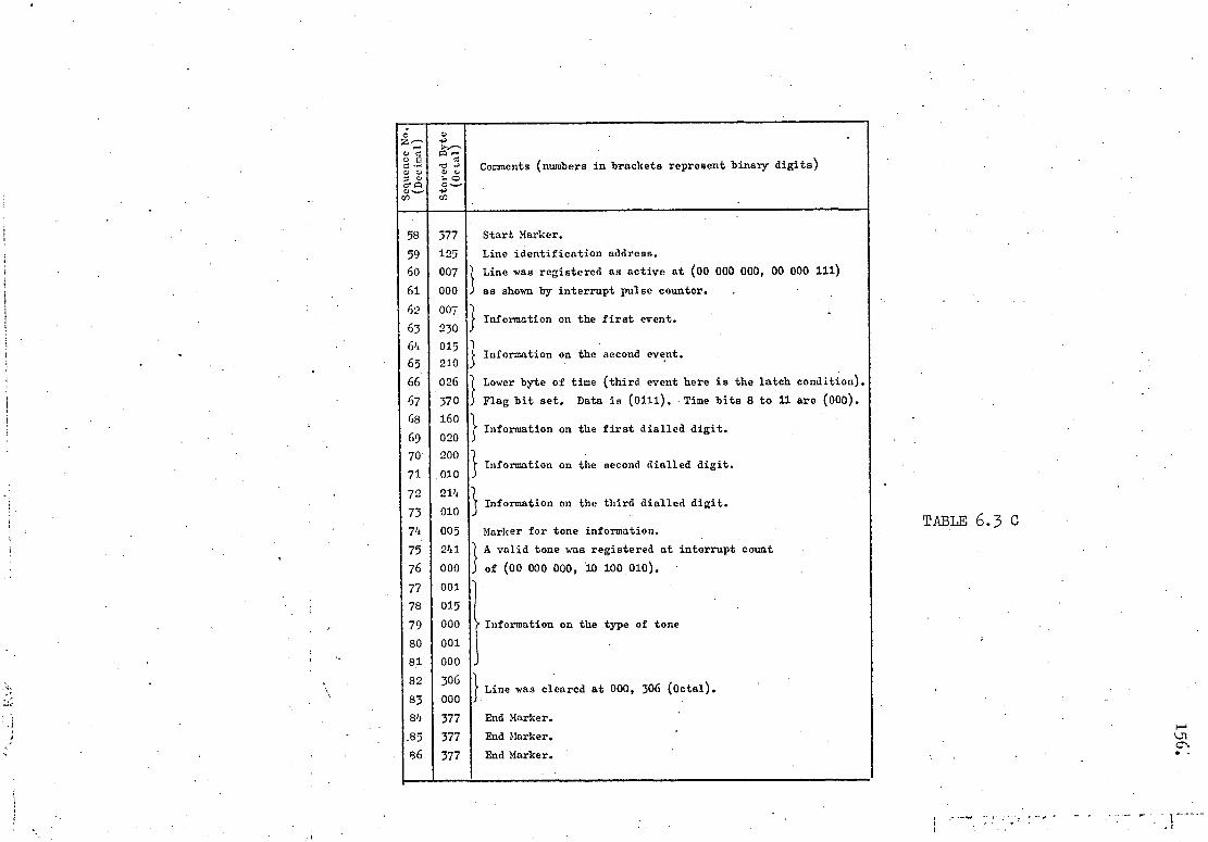
Sequ
ence
No.
(D
ecim
a l)
Stored
Byte
(O
ctal
)
Comments (numbers in brackets represent binary digits)
58 377 Start Marker.
59 125 Line identification address.
60 007 "t Line was registered as active at (00 000 000, 00 000 111)
61 000 as shown by interrupt pulse counter. .
62 007 ) . t Information on the first event. 1 63 230
64 015
65 210 Information on the second event.
66 026 Lower byte of time (third event here is the latch condition).
) 67 370 Flag bit set. Data is (0111). Time bits 8 to 11 are (000).
68 160 Information on the first dialled digit.
69 020
70 200 •• Information on the second dialled digit.
71 .010
72 214 Information on the third dialled digit.
73 010
74 005 Marker for tone information.
75 241 A valid tone was registered at interrupt count
j 76 000 of (00 000 000, 110 100 010).
77 001
78 015
79 000 Information on the type of tone
80 001 .
81 000 ,
82' 306 l
83 000 1 Line was cleared at 000, 306 (Octal).
84 377 End Marker.
.85 377 End Marker.
86 377 End Marker.
TABLE 6.3 C

latched at the interrupt count represented by (00 000 000, 00 010 110)
in binary or 000, 026 in two Octal bytes. The program did not call the
input subroutine when it encountered the registered line whose group
was latched; instead, the code of (01 111) was assumed as the input
data for such a line. This code was ignored by the program during
the data analysis.
Table 6.3A, Sequence No. 10, shows that line 123 received the
first break pulse at interrupt count of 000, 025 (Octal bytes).
Therefore, pointer C was left at Point C' in Table 6.21 when the
group was latched. The latch was lifted when line 123 was declared
"clear" at interrupt count 000, 153 (Octal bytes) as entered in
Table 6.3A, Sequence Nos. 24 and 25. Access to line 125 (shown by
C'+1) started in the next program cycle and continued until the
clearance was reached. It was understood that in real life situations
the call on a typical unlatched line of a latched group would continue
its normal progress and, therefore, any information collected from
such a line after the "unlatching" of the group would remain
unreliable.
Data bytes of short duration were interpreted as erroneous
data. Therefore, the procedure for tone identification was delayed by
one cycle in order to ensure the validity of the received data. The
samples were counted from the time the presence of the tone was,.•
confirmed and no more data validity check was performed on the
following samples in order to reduce the execution time. The margin
between the number of samples, expected for each type of the tones,
was relied upon to minimise the effect of false data.
The "on-hook" state was registered 180 ms after the actual
replacement of the handset to ensure the clearance of the line. Any
discrepancy in the actual and registered time of an event could be
compensated' for during the interpretation of the information, hence extra
157.
158.. .
programming steps were avoided.
6.10 OFF-LINE TRANSLATION OF CALL DETAILS
A Fortran program has been developed on a main-frame
computer in order to interpret the stored information and provide
comprehensive print outs.
Fig. 6.12 shows the flow chart of the Fortran program
which is listed in Appendix 6. This program takes a segment of.
the stored information consisting of blocks of call detail. The
segment is then scanned in search of start and end markers of a
complete block. The identified block is then scanned and various
pieces of information, recognised by their preceding markers, are
extracted. If an incomplete block is encountered at the end of
each segment, the remaining portion of the block is sought in the
next segment during the subsequent runs of the program.
Pre-dialling information is interpreted as "off-hook",
"dial tone", and "start dialling" events according to the binary
format of the collected data. Unrecognisable events are left blank;
these appear as zeros when printed out.
Although the College exchange uses a 4-digit dialling
scheme, the Fortran program searches for up to six dialled digits
in an attempt to sort out possible false information e.g. break
pulses of short duration which were not rejected by the micro-.-'
computer as they could have been due to the ringing current).
Non-dialled digits are printed as digit 10.
The total number of samples counted during the presence of
the 400 Hz tone and for . a period specified by the registered number
of 0.5 second intervals, is examined. The result of the comparison

between the obtained number of samples and the expected number,
indicates the type of the tone heard on the line. Unrecognisable
tones are accompanied with "?" when printed out.
6.11 EXPERIMENTAL RESULTS
The microcomputer was connected to a telephone line of
College exchange using the interface circuit of Fig. 5.9. The line
was then used for placing and receiving calls while the state of
the line was being sampled at intervals of 20 ms. The samples were
analysed by the microcomputer and the stored information was made
available, through a data file, to the off-line computer. The
printout of the results is shown in Figs. 6.13 to 6.16.
Fig. 6.13a shows a segment of memory bytes (in Octal
format) containing three complete blocks of information separated by
markers (four consecutive 3771 s). Different line identification
addresses were arbitrarily assigned to the monitored line during
various experiments.
Fig. 6.13b shows that the line (addressed as 100) was
called and_the conversation lasted for 15.3 seconds. Fig. 6.13c
gives the results obtained from the same line (addressed differently)
when a call was directed to the aphone number 4093 (note: digit 10
represents undialled digits). Dial tone was returned to the caller
0.7 seconds after the receiver was lifted. The caller then waited
for two seconds before he proceeded to dial the number with the
average inter-digit pause of 2.2 seconds. The conversation between
the two took a maximum of 2.minutes and 26.88 seconds (allowing for
159.

16o.
the maximum of 2.04 seconds error in the time registered for the
answer and the 180 ms delay in the registered on—hook time).
The effect of transient voltage swings during the dialling
period (see Fig. 5.10, point C) can be seen in Fig. 6.13d.
The number 3153 was dialled in this case, but transients
caused by the extension of the line to the next selector produced
short break pulses. These pulses appeared to the microcomputer as
pulses produced by the ringing current and were, therefore, counted
twice, giving a spurious digit of even value. Details of the call
(Fig. 6.13d) also support this argument as they show an unexpected
inter—digit pause of 0.36 seconds between the second and the third
dialled digits.
A further example of spurious digit appearing on the final
results can be seen in Figs. 6.14b and 6.16b and c. These digits
could be identified by their position on the dialled number (after
the second or the fourth digit) and their short inter—digit pause,
especially when it appeared after the second dialled digit.
In order to avoid spurious digits, the Teletraffic
Monitoring Program should be modified slightly. The program identifies
short break pulses before taking a. specific action as the result
of the identification. If the program takes no action on receipt
of short pulses, then no spurious digit would be registered. The
ringing current can then be recognized by its characteristic of
producing high voltage swings (± 75 volts at least). A third—level
detector can be included in Fig. 5.16 to detect any positive voltage
swings. .The output of this level detector, then , increases the bit
161.
count of the sampled data by One (four bits in each sample) without
upsetting the arrangement of Fig. 5.16 as four bits of data are
already included in the design. The analysis subroutine can then
check this bit in order to determine the status of the line as a
called or a calling linea
6.12 AN ESTIMATION OF THE RUN TIME OF THE TELETRAFFIC MONITORING PROGRAM
The number of active lines which can be successfully
monitored by the microcomputer depends upon the execution time of the
program. Program execution time can normally be accurately predicted
by counting the number of machine cycles involved. A reasonable
estimate of the run time can also be obtained from the product of •
the number of instructions and the average instruction cycle time.
The large number of subroutines and conditional loops in
the case of the monitoring program does not allow the above methods
to be deployed without a considerable difficulty. An alternative.
method was therefore sought whereby the execution of the program
was interrupted by time pulses of a known frequency. The running
of the program was initiated by the first interrupt pulse and was
halted by the next, where the condition of a flag placed at the end
of the program was examined.
If the flag was set i.e. the program was completed),
the operation was resumed when the next sampling interrupt reset the
flag and also retriggered the program. If the flag was caught reset
i.e. the program could not get to its end), the interrupt was
disabled. and the operation halted. The program execution time was
then taken to be equal to the minimum interval between the interrupt
pulses which did not encounter a reset flag.

162.
The results can only be taken as an indication of the times, .
errors being mainly due to inaccuracy in the interrupt frequency
adjustment and in the measurement equipment used.
6.12.1 Minimum Analysis Time
Each active line is expected to change its state within
a short transition period and remain in the new state for a
relatively longer period. Therefore, a large proportion of the
samples taken from each active line are expected not to indicate a
change of state.
The execution time of the analysis subroutine was probed
for the condition where the program was only capable of scanning
one active line which remained at a steady state. The capability
of the program was then increased to monitor two steady lines and
the execution time was again measured. Since the preliminary
operations prior to the analysis of input data were the same in both
cases and the program did not search for any further active lines,
the difference in the execution times was attributed to the burden
imposed on the program by the presence of the second active line.
The tests were repeated and yielded the following results:
Number of Maximum Interrupt Minimum Interrupt active lines Frequency Period (1/F)
1 442 Hz. 2.26 ms.
2 309 Hz. 3.23 ms.
3 241 Hz. 4.15 ms.
4 202 Hz. 4.95 ms.
TABLE 6.4

From the above results, the minimum time required to
analyse the input data for each active line was assessed to be of
the order of 0.9 ms.
6.12.2 Typical Analysis Time
The same procedure was adopted to estimate the time spent
on analysing the condition of an active line during the presence of
the 400 Hz tone. The measured time of 1.84 ms. is taken as a
typical analysis time, since the program, on average, spent more
time analysing the tone data than any other input information. It
should be noted that the time estimates include the data input time
which is related to the number of instructions in the input
subroutine and the line identification address.
6.12.3 Overall Program Execution Time
Further tests revealed that the preliminary operations
prior to data analysis take an average of 1.3 ms. to be completed.
The low priority search for a new active line was also estimated
to require 0.9 ms. of the program running time for each eight
inactive lines. Therefore, the program can spend more than half
of its available time (20 ms.) searching for one active line among
the 96 inactive lines.
Assuming the above estimated results, the program is
unable to monitor more than nine active lines at a time. In this
case the total program execution time prior to any search for a
new active line is equal to:
163.
(1.84 x 9) • 1.3 = 17.86 ms.

leaving 2.14 ms. for low priority operations. Therefore up to
18 inactive lines may be examined during each program cycle,
implying a full scan of all remaining inactive lines at a rate of
once every 100 ms (five program cycles).
Since the available time does not allow for any further
low priority operation, the microprocessor has to be exempted from
participating in any data unloading task unless this is only a very
minor load on the processor1s time.
The true average execution time was expected to be lower
than the estimated average. The tested program used indirect "Jump"
instructions to transfer the flow of program. This method was
adopted during the development state so that blocks of program
instructions could be relocated without any change in the address
bytes of other instructions. For example, "Jump from each An to B"
was performed through location C. Therefore, if the absolute
address of B changed, only the .content of C needed to be modified
without any change in Al, A2, ..., An.
The method of programming was influenced by the size of
the available RAM (less than 3 kilo bytes), as well as the desire
to develop the program into several modules which could be tested
or changed independently. This led to a number of generalized
subroutines which helped to reduce the number of program instructions.
But the frequent use of the "CALL" instruction and the number of
program loops, intended to reduce the program size, increased the
execution time of the overall program.
Direct addressing is to .be used on the final version of the program. This will seduce program execution time.
164.

165.
The efficiency of the program, in terms of the execution
time, was expected to improve if its modular structure was broken
into several special purpose program blocks used to fulfil
particular requirements. The price to pay would then be an increased-
memory requirement and greater debugging problems.

INPUT NEW DATA FOR ALL REGISTERED LINES WHICH ARE NOT RECEIVING 400 HZ TONE (ISE BUSY TABLE)
INPUT NEW DATA FOR ALL REGISTERED LINES WHICH MAY BE RECEIVE NG 400 HZ TONE (USE TONE TABLE)
1 ANALYSE THE NEW DATA FOR EACH OF THE REGISTERED
LINES
YES
RESET OVERFLOW FLAG
SCAN FIRST INACTIVE LINE EBI NEXT ITNLATCIIED GROUP
RESET POINTER TO FIRST
NO TROUP OF LINES
CONTINUE OTIIER BACKGROUND JOBS
OR HALT
SCAN NEXT- INACTIVE LINE
(UNLATCHED GROUP)
REGISTER LINE ADDRESS AND OFF-HOOK TIME
REIURN TO THE UNFINISHED JOB
INITIALIZE PAIWIETF.RS
STOP
166.
Flow Chari; of the Main Program.
Fig. 6.1

START DIALLING 011)
I i E
ON-HOOK (000)
OFF-HOOK (011)
ti
Incomplete rotation of dial
TONE-OFF THE LINE (001)
TONE-ON THE LINE 101)
ANSWER (001)
CHANGE TO NEXT SELECTOR (019.
DIAL TONE (001)
DIAL PULSE (BREAK 000)
DIAL PULSE (MAKE) 011)
V END OF DIAL PULSES
(001) OR (011)
167.
States of a line .during call setup
STATE OF LINE
(3 bits of output of interface circuit )
Key: Fig. 6.2

168.
ON-HOOK (000)
OFF-HOOK (Oil)
PULSE DUE TO RINGING CURRENT
(BRFAIC) (000)
PULSE DUE TO RINGING CURRENT
(MAKE) 1011)
ANSWER ic
States of a called line
STATE OF LINE Key: (3 bits output of
interface . circuit
Fig. 6.3

1 lines K+56 to K+63
(not latched)
t lines lines K+24
K to to K+31 K+7
(latched) (not latched)
169.
-g-Collate--.------.Analyse and save data
Search- Dump-+
HIGH PRIORITY ----LOW PRIORITY-3-
ONE PROGRAM CYCLE(20 ms)
Fig. 6.4 Work scheduling of a
program cycle
line K+7 ((active)
line K+2 line K (active)) ((inactive)
1 0 0 0 0 1 0 0
0 0 0 0 1 0 0 0
(a) Line Flag Byte
(b) Line Group Flag Byte
Fig. 6.5

an
tis .
uau
emx
ad
V/
6—bytes
INFORMATION BLOCK (
b) FOR A CALLED LINE.
BLOCK FLAG
NEW DATA
EVENT COUNTER
ADDRESS OF NEXT LOCATION IN
PERMANENT SAVE
LAST DATA
TIME OF THE LAST DATA
START MARKER
LINE ADDRESS
START RINGING . TIME
RINGING MARKER
RINGING MARKER
ANSWER MARKER
ANSWER TIMING INFORMATION
CLEAR TIMING INFORMATION
I i Unused locations
I ~
170.
INFORMATION BLOCK POR A CALLING LINE; a
BLOCK FLAG
NEW DATA
EVENT COUNTER
ADDRESS OF NEXT LOCATION IN
PERMANENT SAVE
LAST DATA
TIME OF THE LAST DATA
START MARKER
LINE ADDRESS
OFF—BOOK 3—bytes
TIME
TONE MARKER
TONE TIMING INFORMATION
TYPE OF TONE ' 11\'r VfL`1111JUAN
AN SW IR MARKER
3-1 ANSWER TIMING INFORMATION
CLEAR TIMING INFORMATION
2-1
END MARKERS 3-1
Unused locations
aces
.Sx
exo d
moj
PRE—DIALLING 5EVENTS AND THEIRS 6—bytes
REGISTERED TIME
DIALLED NUMBERS AND THEIR REGISTERED 8—bytes
TIME
3—bytes
5—bytes
ytes
ytes
ytes
Fig4 6.6

171.
Pointer (Initial value)
Pointer (next value)
POINTER VALUE
LINE ADDRESS (K)
BLOCK ADDRESS
LINE ADDRESS (M)
BLOCK ADDRESS
i
END-OF-TABLE FLAG
POINTER VALUE
LINE ADDRESS (Ai)
BLOCK ADDRESS
FREE LOCATION
FREE LOCATION
END-OF-TABLE FLAG
Pointer (Initial)
Pointer (next value)
(a)
(b)
BUSY-TABLE
TONE-TABLE
Lines K and M are busy.
Line M is latched. .
Fig. 6.7

:(Arrows Represent the Transition Between Two Possible Events)
Fig. 6.8 Basic Operations Carried Out During the Analysis Stage
tone on
LINE IS RECEIVLNG TONE (400 ❑Z)
tone tone
off on
CHEEK EVENT COUNTER TO FIND THE PREVIOUS STAS
OF CALL
IIA'KNOWN
CLEAR 7
CALLED LINE
Assul 7 CLEAR ?
ANSWER
1
H
w
DIALLLNG PERIOD
;pull inter digit trein--* pause
O 0 h0
PRE-.DIALLIrG S7AT Z
off .=n1 1.00'4 —* tone —"
BREAK PULSES ON THE LINE

T 0 T T T T T T T T T T C C C
higher byte
lower byte
s0 1 4
bits of ial count
11 bits of time
173:
higher byte byte
X DJ
D T T T T T T T T T T T
1-1
4.1 4-- 4 bits of data
11. bits of time
(a)
Storage Format for Pre-Dialling Events
(b)
Storage Format for Dialled Digits
Fig. 6.9

Type of Exchange'
Type of Tone
Duration of cadences in seconds,
(Tone condition) Tone Frequency=400 HZ
Integer multiple of actual per- iod consid- ered.
Total tone-on period ,during a cycle of
3 seconds
(Units in Seconds)
No.of sauples(nOtaken during total tone-on period (rounded off to the nearest integer).
.Sampling rate=50 :IZ
ON OFF ON ' OFF ON OFF normal +10% -10% normal +10 -10% NON-PERIODIC PERIODIC condition tolerance tolerance condition tolerance toleranc•
EQuIF:'~a • ENGAGED .
-- -- 0.4 0.35 0.225 0.525 2 ,
1.25 1.375 1.125 62 69 56
BUSY -- -- . 0.375 0.375 0.375 0.375 ' 4 1.50 • 1.65 1.35 75. 82 67
RINGING 0.35 0.22 0.4 .0.2 0.4 2.0 1 1.15 1.265 1.035 '57 63 52
NU -- -- J -- ✓ -- Non-periodiD 3.0 3.0 3.0 150 150 150
IA;P
H RIA
L CO
LLEG E
IN
TERN
AL
EXCH
.
•
BUSY -- -- 0.75 0.75 0.75 0.75 2 1.5 1.65 1.35 .75 82 67
RINGING -- -- 0.4 0.2 0.4 2.0 1 0.8 0.88 0.72 40 44 36
NU -- -- I
-- I -- • Non-periodi3 3.0 3.0 3.0 .150 150 150
Fig. 6.10
Sequence of Various Tones

MARKER,
LINE ADDRESS
CALLED TIME
MARKER -(CALLED LINE)
MARKER (ANSWER)
ANSWER TIME
CLEAR TIME
MARKE1t
Byte 1
2
3
1'
5
6
10
Byte 1
2
3
4
5
6
7
8
9
10
11
18
19
20
21
22
23
24
25
26
27
(a) 28
29
30
175.
MARKER
LINE ADDRESS
OFF-HOOK TIME
TIME (LOWER, BYTE)
Event Code Time (5-bits) (3-bits)
TIME (LOWER BYTE)
Dialled Time Digit (3-bits)
MARKER (TONE)
TONE TIME
2 SECOND COUNTER
TOTAL COUNTER
PRELIMINARY COUNTER
MARKER (ANSWER)
ANSWER TIME
CLEAR TIME
MARKER
A block of stored information on a called line
A block of stored information on a calling line
Fig. 6.11

STAltT -,
l~l ;-UUZE \':\lIL\HIJ:S I ,
II 4L--_.-----..
KO
:-:0
FI~D TYPE OF T')~l
/[ /(:,\L~
< i\."~\;]:~~ to Fl'll ,\.~IS;EP.. TIXE
~\T)~.(~ .. ! L ___ IlL\!' TIl'\1: I ._-,.-,- --
r Fl\()li~i!: or ~.\It r 1'0 I>J ,\/,
I F1:,; /) /lU I. LEI) j. I (I J 1S: AXD T!lElH HI.H.1.1 ~G I
rIm;
Fig. 6.12
Data Processing Program
~
"'..] 0\

col )
STOP
SZETFLe r!Or. •"~+d✓• U [-LG • li?. V G1+Y. YnrK1i . 4 i i L i t E ' PEFORt1ATTED.• LINNE. ADDR., (OCTAL) 1 -- 211 =- DIALLED -- .4 0 9 3 10 10 -. CALL ANSWERED...
DETAILS]
TELEPHONE TRAFFIC STUDIES ;SUB:CAMPEP FEHAVIOUR)
4-DIGIT NUMBERS DIALLED.I9t•OFE DIGIT '10". TIMING ACCVRA'YTO WITHIN e ms .(.ITHIN 2.04 SEC.FOR CALLER RECEIVING ANISWER.>
DATA IN K31I)
377 377 377 100 343 042.004 004 006 011.
045 006 050 377 377 377 377 211 071 073
071 233 134 213 300 233 342 043 107 124
310 1 1 4 i60 035 005 170 075 006 044 000
247 000 006 018 106 135 136 377 377 377
377 100 316 155 616 233 350 213 057 234
121 034 535 014 257 044 357 054 100 035
10 170 155 006 124 000 1.01 000 276 156
377 377 377 377 377 012 013 014 015 016
)17 020 021 022 026 024 025 026316 317
EVENT.
OFF-H[}OK ON-HOOK DIAL TONE
T1t E ii1IN.3
5 8 5
7 1E' 1EC.2
3.22 3.14 3.92 ,
'START DIALLING 5 5.92 1 DIGIT DIALLED 5 • 6.60 2 DIGIT DIALLED 5 8.62 3 DIGIT DIALLED 5 11.20 4 DIGIT DIALLED 5 13.26 5 DIGIT DIALLED 0 0
(c) 6 DIGIT DIALLED RING TONE
0 5
0 14.72
ANSWER 3 38.12
LIUE ADDR.:OCTAL): -- 100 -- DIALLED --. 3 1 04 5 3 10 --CALL 1?07.ANSUEREI
DETAILSI
Euct1 r
CFF-HDQK Orf-HOOK
T It1E:t'1l1l.)
9 9
TIt E(SEC-.
11.96 27. 00
DIAL T17NE 9 12.48 START DIALLING 9 13.90
1 DIGIT DIALLED 9 14.59 2 DIr31T DIALLED 9 16.10 3 Dlr3IT DIALLED 9 16.46 4 DIGIT DIALLED 9 27.74 5 DIGIT DIALLED 9 18.36 6 DIGIT DIALLED 0 0
PSY TONE 9 20.49 ANSWER 0 0
(Q )
.
LINE ADDR.(OCTFL): -- 100 -- WAS CALLED
DETAIL::
EVENT
TIHE(M1N.) TIME(SEC.)
RINGING 2 56.62 ANSWER 3 9.62 DID CF CALL 3 24.92
Fig. 6.13
(a) Call Details (Microcomputer Output); (b)-(d) Call Details (Computer Output)
\ L)
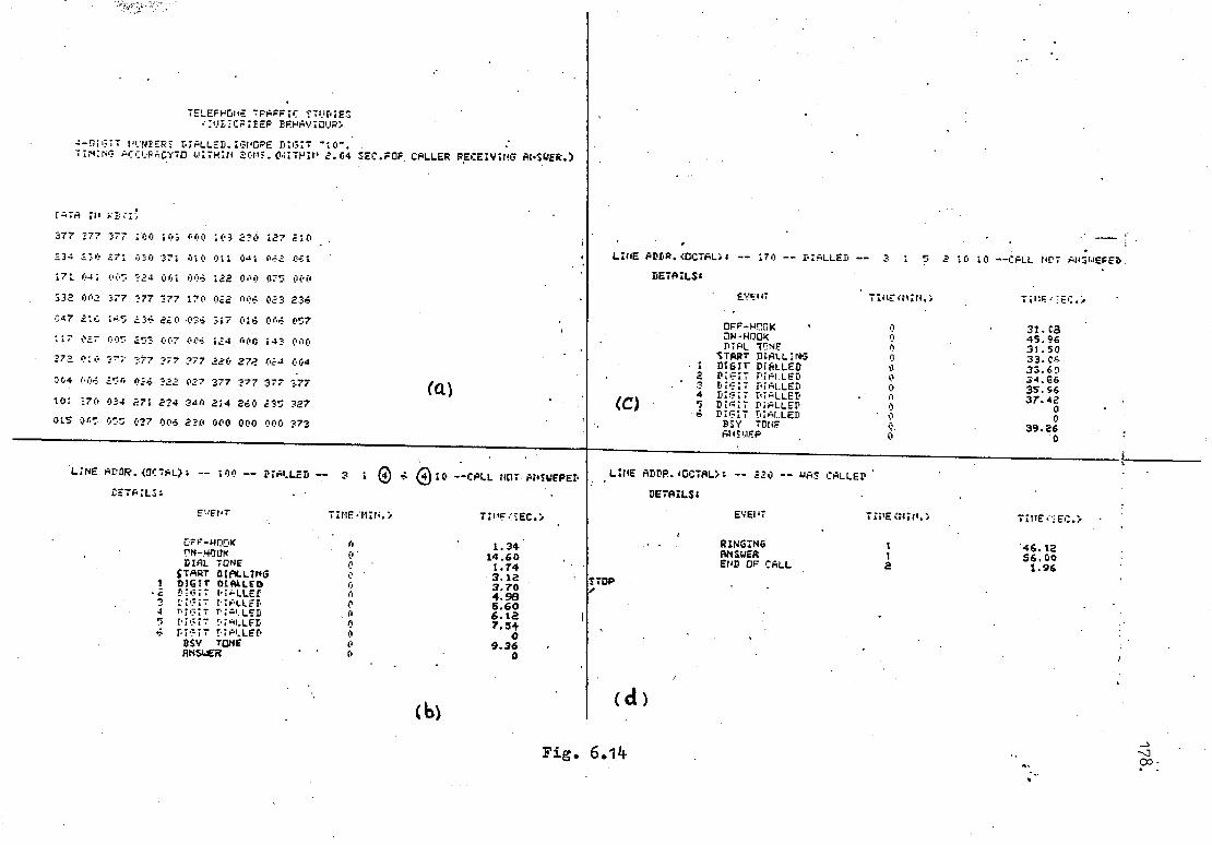
LINE R.:OCTAL -- 170 -- DIALLED -- 2 1 5 2 10 10 --CALL NOT ANIuEFED DETAILS;
EVENT TfMIN., TINEwIEC.e
CFF-HDOK aN-HOOK DIAL TCNE
START DIALLING 1 DIGIT- DIALLED 2 DIGIT DIALLED
DIGIT DIALLED 4 DIGIT DIALLED
DIGIT DIALLED -• 6 DIGIT 1.11ALLED
BSY TONF ANSWEA
(C)
0
0
A 0
0. 0
31.08 45.96 31.50 39.06 33.60 34.06 35.56 37.42
0 0
39.26 0
LINE ADDR. 40CIALi; 320 WAS CALLED
DETAILS;
EVENT TINE:MIN.) TINE;'IEC.)
1 '46.12 I 56.00 2 1.96
RINGING ANSWER EIJD OF CALL
STOP I.
TELEF346hE TF1AFFIC 17-71.1DIES •-:MtICF1FEP BEHAVIOUR:
-!GIT Pum1ER1 DIALLED.IGVOPE DIGIT "10. TImING ACCI,F,;CYTO wITHIN 2045. (iAITHIV 2.04 SEC.F0F CALLER RECEIVING ANSUER.)
IATA ;0
377 777 377 100 103 000 103 270 127 21e'
334 .110 371 070 371 010 011 041 061
173. 04: 005 324 001 00 122 000 075 oeo
332 002 377 777 177 170 02'2 006 027 276
047 316 1.5 236 220 .03; 317 016 604 057
117 027 005 353 007 006 134 600 147 e0o
773 0:0 27;. 777 777 777 220 272 024 604
0c4 006 a.::n 016 S22 027 377 777 377 377 101 370 034 271•274 34n 214 260 275 727
015 OAS OS'S 017 006 230 000 000 000 773
(a)
3 LINE Atß.(DTAL): -- 100 -- D/ALLED -- 3 1 e 6 (i)10 --CALL HOT ANSWERED
ZETAILS:
EvEv:
cr;F-HOOK 17N-NO11K
TIME.14IN.i
0 0'
TINE(IEC.i .
1.34 14.60 DIAL TONE 0 1.74 START OIALL/NG 0 . 3.12 1 D10IT DIALLED 0 3.70 .3 DIGIT fLLEr n 4.98 2 r7iT u1ALLED 0 5.60 4 r.p.7.;T r:AkLSD . n 6.12 5 DIGIT .1.40..LFD 0 7.5+
4 D7 3IT !.IALLEP 0 0 BSV Tom 6 9.36 ANSWER 0 0
(d ) (b)
Fig. 6.14

EVENT
OFF-HOOK 011-Hook DIAL TONE
;'AFT DIALLING DIGIT DIALLED DIGIT DIALLĒD DIGIT DIALLED DIGIT DIALLED DIGIT DIALLED DIGIT DIALLED 3SY TONE R14 I,IEP
Q•iA
a W
ru-•
(C)
(e)
STOP
LINE ADDR.(OCTAL):--- 100 DIALLED 10 10 10 10 10 10 --CALL NOT ANSILEFED •
DETAILS:
-) 0.
1-1
fV ~
•
EVENT TIr-+E rl:N.) T;rtE SEC.)
OFF-HOOK 4 28.90 ON-HOOK 5 .70 DIAL TONE 4 39.20
7TAPT 'IALLING 4 51.02 DIGIT DIALLED DIGIT DIALLED
0 0
• 0 0
DIGIT DIALLED 0 0 DIGIT DIALLED '0, 0 DIGIT DIALLED 0 • 0 DIGIT DIALLED 0 . 0
TONE 0 (; ANSWER 0 0
27.04 48.26 27.84 32. 00 32.78
0 0 0 0 0.
30.62 • 0
TELEPHONE TPAFFIC STUDIES f 'J 2CPIFER FEHAVIClJR)
4-DIGIT 'Minn DIALLED. IGNOPE DIGIT "10". • TINING ACCUFACYTO WITHIN 20tS..IWITHIN 2.04 SEC.FOP CALLER RECEIVING ANSWER.)
LATA IN K2fI:
377 377 377 103 270 034 S71 234 340 214
260 235 227 015 005 055 037 006 230 000'
0000 000 373 940 377 377 377 377 377 170
022 ((6 023 216 047 216 165 226 220 026
317 015 005 (57 117 027 005 253 007 006'
124 00€ 143 000 272- 010 ?77 '377 377 377
377 22, 134 053 004 004 021 057 ?77 377
377 277 10P 200 064 201 234 210 216 327 (a) 230 250.012 273 072 377 377 377 277 377
377 020 ('21 022 023 024 025 026 516 317
_ 1 5 2 10
TIt1E(NIN•)
0 0 0 0 - 0 0 0 0 0 0 0 0
10 --CALL NOT APS bEFEI•
TIfE:EEC.:
31.08 45.96 31.50 33.06 33.60 34.66 35.96 37.42
0 0
39.26 0
LINE ADDR.«OCTAL): -- '232 -- WAS CALLED
DETAILS:
EVENT Tit4EfFl:rr.) T:tlE i;EC.)
RINGING 3 42.00 ANSWER 0 0 END CF CALL 4 .98
" LINE ADDR.<DCTAL): -- 170 -- DIALLED --
.DETAILS:
(d
OFF-PPOK 2 CI-HOOK 2 . DIAL. TONE 2
:TAFT DIALLING a 1 DIGIT DIALLED 2 2 DIGIT DIAI.LED 0 3 D1' :7 T.IALLED 0 4 DIGIT DIALLED 0 5 DIGIT DIALLED 0 6 DIGIT DIALLED 0
MU. TOPE 2 ANSWER 0
LINE F DDP.fOCTFL:: -- 103 -- DIALLED -- 1 10 10 10 I0 10 --CALL HOT PNSWEPEI'
DETAILS:
EVENT
T I I tE (M IN.) T 1I1E "2 EEC. )
(b)
Fig. 6.15

LINE ADDR.00CTAL>: -- 143 -- DIALLED
' DETAILS:
EVENT
OFF—HOCK . ON—HOOK
-- ? 1 5
Tir1E 4NiN.>
9 10
10 --CALL POT ANSNEREI
T1112.'EC.>
54.98 10.54
DIAL TOI+E 9 55.68
1 S7AF'7 DIALLING DIGIT DIALLED
9 9
59.24 59.52
2 DIGIT DIALLED 10 1.74 '3 DIGIT DIALLED 10 3.56 4 DIGIT DIALLED 10 5.92 5 DIGIT DIALLED 1 0 6.52 b DIGIT DIALLED 0
SsIV TONE 10 7.72 ANSWER 0 0
STOP
TELET-HCNE 7Fh=F1C STLP;ES :' BSCP;FEP FEHAV;O!.P>
4—DIGIT NI+r?rEF'' rr?LLEG. IGHOPE DIGIT "10". p.r,_uPAC'r'7C MITHIN 20r+ . • 1ITNIN 2.04 IEC.FCR CALLER RECEIVING ANSWER.>
S47F ils
377 377 377 377 146 065 157 066 237 146
217 247 237 310 037 023 010 046 020 147
050 273 030 354 020 005 365 160 006 tel
000 031 001 255 163 377 377 377 377 143
065 164 066 234 142 214 366 234 030 035
207 015 342 055 130 036 212 026 005 236
;66 006 115 000 000 000 123 167 3-77 377
377 374 375 376 377 000 001 002 003 004
005 ooh 007 010 011 012 013 014 015 016
017 020 021 022 023 024 025 026 316 317
L71€ ADDR..Oc7 L.: -- 146 -- D;ALLEP --
DETAILS:
E EPT
3 1 02
T;1'E(11014.>
U--CALL NOT ANSWERED
TINE•=EC.>
CFF-NCriK 9 29.38 ON-P9OK . 9 52.26 DIAL TONE 9 30.36
START DIALLING 9 31.66 1 NGI: P;ALLED 9 32.32 2 DIGIT DIALLED 9 33.82 3 P;•:IT DIALLED 9 34.20 4 DIGIT P;AL.LEP 9 35.50 5 DIGIT DIALLED 9 37.18 6 DIGIT DIALLED 9 33.16
P.77 TUNE ANSWER
9 0
3$.34
i
(a)
(C)
Fig., 6.16
(6) 00 0
181. CHAPTER 7
CONCLUSION AND SUGGESTIONS FOR FURTHER WORK
7.1 CONCLUSION
The aim of the project described in this thesis was to
investigate the possibilities of applying a microprocessor to the
measurement and analysis of telephone traffic. At the time of
commencement, microcomputers were not commercially available at
economic prices and so the first step was to build a microcomputer
suitable for the work. This involved development of an appropriate
system using an available microprocessor and its associated chips,
also the development of the software programs for its operation.
In the next step, a survey of telephone traffic recorders
indicated the need for a cheap, intelligent traffic recorder which -
could provide detailed traffic information with easy data—handling
facilities. The survey also indicated that the largest portion of
the costs involved in traffic sampling was the cost of access
equipment; this had to be cheap and therefore simple in design.
The telephone system was the next field of study. Many
different types of exchange are currently in use. Common control
systems are most favoured at the present time, but are outnumbered
(in the United Kingdom) by the older—fashioned step—by—step
equipment. The study showed, however, that the communicating
language between the subscriber and the exchange has remained relatively
unchanged as technological advances have improved the switching
mechanisms.

182.
As the expertise of subscribers cannot be taken for granted
and the cost of more complicated links between the subscribers and
the exchange cannot be justified, the signalling methods for the
transfer of information from a subscriber to an exchange have remained
fairly simple. However, a wider variety of signals is used to-
return additional information to the subscriber without any
additional equipment in the telephone receiver. As a result of
this fairly simple means of signal detection (e.g. level detectors)
can be used to detect .the subscriber's instructions, but more
complex (and therefore more expensive) devices are needed in order
to understand the'information returned by the exchange.
An interface circuit was developed and methods for sharing
its cost between several .telephone lines were suggested. Tests
carried out on the circuit showed that while the human ear could
ignore sharp transient signals, and that slow electromechanical
exchange equipment remains insensitive to them, these transients
prove to be a problem in design and operation of electronic measure-
ment equipment. Such equipment, operating in an exchange, should
be well protected against interface in such a hostile environment.
It also has to be able to distinguish between noise and the true
signal on its input lines.
A program was then developed for the microcomputer
configured as a teletraffic monitoring instrument. The program for
the detail analysis of a phone call included an algorithm for the
detection of the type of the tone received by the caller. (The
ability to detect the type of the received tone is not included in
the most recently announced microprocessor—controlled traffic
recorder, as is outlined in Chapter 4.)

183. 9
The information collected has been compressed into less
than 50 data bytes. Thus, call details on about 2000 aphone calls
can be stored on one magnetic cassette tape*, considerably reducing
the amount of data handling. (The dumping of the information onto
a cassette tape was not achieved due to the non-availability of. the
unit at the time.)
The system developed employed a•20 ms. scan which proved
to be sufficiently short for the teletraffic monitor, although many
electronic exchanges tend to use a 10 ms scan interval on active
lines. The program timing, as estimated, can allow the system to
operate on up to nine active lines at a time, although due to the
reasonably low traffic on an exchange, a few hundred lines can be
monitored. The program time is used up mainly in scanning active
lines for change in conditions; lines which are inactive can be
relatively quickly scanned for change from inactive into active
mode. The commoning of tone decoder facilities in order to save
substantial costs involves the use of flag bits and thus has proved
to require a fair amount of program time. In both situations, the
use of more hardware would give more time for additional lines to
be monitored. An external scanner, for example, could be used to
probe previously non-active lines, while the processor attends to
those registered as active lines.
In further attempts to increase the number of monitored
lines, faster microprocessors.( .g. Z-80 microprocessors) or more.
than one microprocessor could be considered to perform low and high
priority operations independently.
Racal Digidek Model P.70 can handle 50,000 to 120,000 bytes depending upon the transfer mode (increment or continuous).

The above suggestions are by no means exhaustive; a
true commercial evaluation of the balance between the use of
additional hardware and the program time saved, which could be
used for monitoring more calls, has not been fully investigated.
However, it is estimated that modifications of the
program supported by extra hardware could easily increase the number
of monitored lines to be above eleven. With the assumed traffic
intensity of 0.05 Erlangs, the probability of having more than
eleven active lines, in a group of 96, becomes less than one per
cent. With this modified approach less than one per cent of the
information on a group of 96 lines of the College exchange will be
expected to be lost due to microprocessor overloading. In practice.
this is an acceptable rate of loss of information. It is not
generally necessary to monitor in detail every call; provided
the call has been registered.
Modifications will be needed (see Section 7.2) if the unit
is to run on a Post Office type of electromechanical exchange; the
principles, though, still hold..,
Can microprocessors have an application in the field of
teletraffic engineering? The results collected in this thesis clearly
imply that full teletraffic measurement cannot be carried out on more
than a few tens of lines using a single microprocessor with the
minimum of line interface hardware.
The indications are that the devised system.is capable of
handling the number of simultaneous active lines for a small
exchange or for a medium-sized exchange with low traffic intensity.
However, detailed traffic measurement on these. types of exchange are
184.

185.
not normally crucial.
The traffic monitoring system described monitors all aspects.:.
of a call and all details are retrievable. If some of the information
can be sacrificed more processing time becomes available, the system
then becomes more of a traffic recorder than a call detail analyser.
In conclusion, it is suggested that the application of
microprocessor in teletraffic engineering situation should be viewed
within a spectrum. In the lower order of application, straightforward
busy—or—free tests can be performed on a large number of lines;
this will enable the traffic intensity at a particular time to be
determined together with perhaps some details, say the length of
call. In the higher order of application, it is feasible that the
microprocessor can be used in a Call Detail Analysis System
employed to study subscribers2 behaviour in detail, but here only a
few active lines can be monitored at a time, although a good number
of lines can be attached to the system. Generally, in this latter
situation it is sufficient to accumulate information on a sample of
calls and so the inability of the system to handle all calls is no
great detriment.
7.2 SUGGESTIONS FOR FURTHER WORK
The teletraffic monitoring system developed as described
is at present unsuitable for connection to a public electro-
mechanical or an electronic exchange.
In-order to comply with British Post Office regulations,
the input impedance of the unit will have to be increased to 1 Mc-2.

186.
To enable the system to be used for "coin box lines" and for "party
lines", line voltage reversal must also be detectable. The present
system monitors between one line and the earth; to allow for.
reversals a connection to both lines would have to be made and
additional level detectors would have to be incorporated in the line
interface units.
When coin box calls are to be monitored, an additional
tone (pay tone) will have to be recognised and to do this the
monitoring program will have to be supplemented with additional
instructions and the link to the tone decoder will have to be kept
throughout the length of the call. Outgoing calls from coin boxes
will have to have separate treatment as the line loop in this case
is different to allow for coin insertion, coin detection and pay
tone. These are special lines and therefore require additional hard-
ware and software; no attempt has been made to cater for this aspect
in the report.
7.2.1 A Permanent Storage Medium
In order to perform a continuous teletraffic monitoring,
a permanent storage medium is needed in order to store the collected
information. For the developed system, the use of the DIGIDEK P.70
cassette recorder (Appendix 7) was intended. However, as the
cassette unit was not available at the time this work was completed,
only suggestions on its usage can be made.
Under the control of the described Teletraffic Monitoring
program, a block of 48 memory locations is allocated to each active
line which uses a maximum of 32 bytes to store the information on a

187.
call. Once the•"subscriber clear" state is acknowledged, the whole
information is transferred to a second block of RAM which acts as a
buffer holding the data prior to its transfer to a permanent storage
medium for later processing on an off-line computer.
Use can also be made of the Direct Memory Access DMA).
property of the microprocessor for the transfer of data from the
RAM buffer into a cassette recorder. When N bytes of RAM are filled
up with information, the processor can give an enable signal to a
separate hardware timing device which externally controls the storage
units. The device, after an initial period of t1 seconds, intended
to allow for the start and speed up of the tape, produces N strobe
pulses of duration I and at the frequency of litt,, where t2 is determined by the recording speed of the storage medium. The strobe
pulse "HOLD" the microprocessor, which would, then issue an acknowledge
(HLDA) signal. The address and data busses are then under the control
of the peripheral device during the hold period equal to T. The
device then takes a byte of data, addressed by an N-state counter,
before it withdraws the "HOLD" request. As the operation is executed
under the hardware control and need only hold the bus lines for a
few microseconds, the transfer period can be shorter than an
instruction cycle. This process may have to be repeated a number of
times in order to transfer the whole of the data, but the interruption
to normal processing need not be more than a few microseconds in a
number of non.-sequential sampling periods.
Assuming that the intended cassette recorder is used, the
initial period of t1 is about 100 ms and t2 need not be longer than
1.5 ms. The period I depends upon the memory access time, and the

188. •
speed of latching of the collected data into the input buffer of
the storage unit. As this period is much shorter than the recording
period, the cassette can record under its continuous mode, which
gives a more efficient use of the tape. At the end of the next
N x t2 seconds, where N is the number of bytes, a signal issued by
the hardware stops the recorder.
This method does not overcome the need for the transfer
of information from the working storage blocks into the RAM which is
to act as•the buffer. In order to perform the transfer straight
from the working storage block into the recorder, more complex hard-
ware is needed. As the number of bytes of information can vary, the
start and end addresses of the blocks must be known to the hardware
counter which generates the addresses for DMA. Programmable counters
can be used.to generate the desired addresses, and these can be set
by the microprocessor.
7.3 FURTHER WORK ON THE RESULTS
The off—line computer processing could be enhanced to
produce further statistical information and tabulation as necessary.
The program written to date has been aimed at obtaining basic call
information, but accumulation of call times, their averages,:
standard deviations and other factors could be added if required.
Classification as to users and types of users could also be
incorporated, as too could billing of users.
APPENDIX (1)
The operation of each key on the console
of the developed microcomputer initiates
a sequence of instructions which are shown
in the form of the following flowcharts.
189.

ENABLE INTERRUPT
RESET ACC.
RESET REGISTER IDINTIFTER COUNTER
OUTPUT A CODE TO THE DISPLAY
.. SET SP
TIALT
Control keys (Rastart 1): These keys include: RUN, CONTINUE,
LOAD ADDRESS FOR SINGLE STEP, SINGLE STEP, EXAM FORWARD, EXAM BACKWARD,
STOP, and READ INTERNAL REGISTERS.
SAYE ACC. & FLAGS
l ENABLE INTERRUPT
PRIORITY CONTROL UNIT
INPUT CONTROL ST:AIIJS WORD
ROUTE THE PROGRAM COUNTER TO THE APPROPRIATE SUBROUTINE
RESTORE PROGIL\M STATES WORD AT THE END OF EACH SITROUTINT AND
ENABLE INTER' TT
HALT
190.
RESET

GO TO ADDR. INPUT SUBROL^rINES
CLEAR IlL CHECK ADDRESS DI:;I'r
.COUNTFr1 FOIL HIGIIIR OR LOWER ADDR. ENTRY . C1.1:\it AU ;;:E;1-:.S
DIGIT CO 1I'IR '
Yes
!PAD 'HIE NEV 3 IIIT ENTRY INTO
II-'.ti1;T)z'I'I!1
RI•;.1 u61; 1'IMII t?I STA TI 5 W01!1)
Nn
Sill L REGISTER LITT BY 3 MACES
LOAD TILE NEW 3-BIT ENTRY INTO L-REGISTER
III ;IT- ADIIRESS
ENTI11•
Ins
SHII1' II-REG. LE'!' 1D TH1IIIE I'IACES
DISPLAY NIN ?ILNo11Y ADDR. AND ITS
CONTENT
Heys 0 tb 7 and CLEAR (Restnrt 2)
RESI?r SP
SAVE I'Itu ;It L`L STATES 'BORDS
L{NA111.E PO lo tL'VY LNT MUTT CONTROL UNIT •
STATS BITS
ELUTE THE PC FOR ADDRESS/DATA INPUT
SHIFT THE CON ENT OF MT-NOLIY ,EFT 1W 3.
?'TACES (ONE or'rAL DIGIT)
KIVIE IN THE NI•W INPUT OCTAL DIGIT INTO TILE LOWER 1-DITS OF TILE
?I:'1671Y CONTENT
DISPLAY 01mORY :\DDItESS AND ITS CONTENT
I RESUME E PRE- INTEitRI,PT FIAG TLTTS AND ACC. AND
CONTROL CONDITIONS
IWLT
ADDR. INPUT ROUTLvE
ENABLE INTI]1IU;L'r AND II/11,T •
Details of control subroutines:
RUN
RESTORE fI211iRAN STATES WORD
ENABLE 1 1 1
INTERRUPT
DlJtl:'Cr 1'C TO THE: ADDRESS SHOWN BY HL
YES
c1.1- : THE CONTENT Or
MI`]ORy POINTED
BY II-L 1EGISTIi . PAIR

EXAM forward/E'CAM backward
ENABLE 1NTEMiWPT AND HALT
CONTINUE
No
iIESLI IRE COUNTER
READ INTERNAL REGISTER .
CLEAR T1lE Ill(Iti ADDit. DISPLAY
Yes
1 No
REGISTER JI)INi1I,1jjt COliNiLH MINTS TO REGISTER
lit•l`:~I l.it PC TO Llll', I t ON X I WITH A .CALL 1 NSIFI'(1I ON
DISPIA': '1lIE t'U\ Iii\ I' O E A('C. (TIlE CONTEXT OF r REGISTER)
IN ALATA DI SP1 A'i
CIIECK IllE COXT 1\T or ita 1sTI]E IDE:NTIFTER
I DISPLAY FLAG BITS IN ONE BYTE FORMAT
NCit}?LFtiT TILE COlINPI.It
1 RESTOit1•: i'lti(iiIN Sl'AIliS w'O1W
AND ENABLE INTERRUPT
•
DI i'LAY ME CON l i 11' OF REGISTER TD NTIF] Ill COUNTER
LO.111 X LOCA l I ON ti 1 ill NOV a.r INS]'RI CTI ON
IOAD N+1 WITH RUT INSTRUCT-10N
HALT
DISPLAY TILE NLW MEMORY' ADDR. A.\') ITS CONTENT
RES? O2L 1'RO61LAM • sTA;'I'S WORD
INC1tLM1:Vt' hi:CRl:1EN'T li-L REGISTER PA Tit
TRANSFER PC TO EXECUTE THE INSTRUCTION IN
LOCATION X
Rr:SI'ORE 11101;R:1N( STATUS TO THEIR VALUE BEFORE TNTElLIUPT AND ENABLE
TNTFIUU?PT
LOAD X 1,0011'10N -WITii "'TEMP" INSTRUCTION
LOAD 'lilE LOWER AND HIGHER ADDRESS OF THE CONTINUE ADDRESS (11IE CONTENTS OF
MPv) IN X+1 A'iD X+2

SINGLE STEP LOAD ADDR. FOR SINGLE STEP
STAi1T ANG ADDRESS IS IN MPS•
CHEM 11111 THE T1TE OI' INST71UCT1ON AND ROUTE
I1IE IROGRA?I ACCORDINGI ,Y
IONE BYTE INSTRUCTION
TWO BYTE INSTRUCTION
1 S1'(1111: THE IAFC:VTADT :
INSTRITTION IO(;ATION X
CHECK THE CU\Y1N '1 O1 MENIIItY PAIR MPy TO
DECIDE ON THE STARTING POINT FOR SINGLE
INSTRL'CTI1)N EXECUTION
MEN STAR I NG ADDRESS IS TN H-1,
THREE BYTE INSTRiICTION
CLEAR THE CONTENT OF MPy
CLEAR THE ADDR. DISPLAY
DISPLAY CODE 111 IN DATA DISPLAY TO
SIGNAL THE READINESS OF THE MACHINE
RESTORE THE STATUS TO TIIE VALUE BEFORE
TIFE L'ETBL,T
ENABLE INTERRUPT AND HALT

S.STP
Yes
IGNORE ITS ECUlION
LOAD THE ADDR. OF
Hal* 1NETRICT/ON
IN M
BI1JUCII GROUP INSTR.
'o
Disable interrupt instr.9
No
LOAD X+1 WITH ELT INSTRUCTION
3-BYTE INSTRUCTIONS NOT INCLUDING BRAND= GROUP
INSTRUCTIONS
!MAO THE (I'l11Elt TWO BYTES INTO (X+1) AND
(X+2) LOCATIONS
LOAD HLT LY X+3 LOAD X+I AND X+2 W1 'TH THE ADDRESS 06 'IThE
SPECIAL ,JUIW LOCATION TN THE ROM
PUT HLT INSTRUCTION INTO X+3
LOAD THE ADDRESS OF NEXT INSTRUCTION IN
I MPy
DISPLAY THE.ADDRESS AND THE CONTENT OF
NEXT 1NSTRUCTIOJ(
CALL INSTRUCTIO }
LOA D Xj.S AND )6{ 2 • Willi THE ADDRESS OF
THE SPECIAL CALL LOCATION IN ROH
RESTORE ALL PRE-INTERRUPT CONDITIONS
ECUTE TH£ SNSTRUCTION 2 IN LOCATION X I -t 1 L. — — —
vo
C PROGRA?I WAS, THEREFORE,\ ALREADY HALTED
LOAD THE GENUINE JUMP ADDRESS
INTO MPy
ONE BYTE INSTRUCTION
CHECK FOR SINGLE BYTE EIi,ASt II GRn(IP INSTRUCTION
Yo a
No
Yea
CHANGE THE HETUILN ADDRESS IN THE
STACK- TOP WITH THE ADDRESS OF
THE SPECIAL RETURN LOCATION IN THE
ROM
PUT THE BRANCH ADDRESS IN AfPy
DISt:LAY THE ADDR. AND THE
CONTENT OF NMI F CE(11TAiII,E +-
INSTTRUCTION (ADDRESSED BY
h4Py)
11,11 BYTE • 1NSTUUUrIIINS
LOAD THE SECOND BYTE INTO THE LOCATION X+1
U'IAD HLT IXI'O X+2 LOCATION
THREE BYTE INSTRUCTIONS
( 3-BYTE BMX cH GROUP INSTRUCTIONS
TO THE ROM?
īt.JiS'1'111t1: ALL PRE-INTERIU11PT
CONDITIONS
j HALT No
PRUGILAM WAS THEREFORE
HALTED
Yes '
LOAD TILE` GENUINE RETURN ADDRESS
IN MPy sn
CALIX. TO THE \ N i,
SPECIAL A PDRj TN ROM / •
Yes irA RAM IYA51! ENDED
rP11C THE RETURN ADDRESS IN TOP
OF THE STACK
THE GENUIN CALL ADDRESS
INTO v

RESTORE PRE- CALL(LNT• CONDITIONS
HALT.
TTY PR O RAM :
TTY STMT UP
RESET USART
/
[LOAD, TOE CONIROL COMMAND INTO USART
LOAD THE START AND END ADDRESSES OF THE MESSAGE L\•TO'H-L AND• DS REGISTER
PAIRS
PRINT OUT THE STORED 1 MESSAGE
IL1RKO RECOGNIZED
9
INPUT THE NEXT BYTE
STORE I`I't I' R.+'I'A Ici MEMoRY
ADVANCE MEN ORI ADDRESS POINTER
No
IALT TIlE PROGRAM •
READ IN FROM TTY OR PAPER TAPE STOP
GET PC FROM STACK TOP
START STORE PC IN Miy AND
DISPLAY IT
LOAD IN THE START AND IND ADDRESSES SET 111E 111T1 DISPLAY TO
123 AS A CODE FOR PC
LNPUT ONE DYTE
CHECK Mt tI START' MARKER TO DE EITIIfl1?
OR A RO/ OE HOLES (177)

196: •
PUNCH PAPER TAPE
rr
PUNCH A IIEADI7i
PUNCH START MARKER
LOAD TIlE S PART AND END ADDRESSES
PUNCH OUT A BYTE
Yes
PUNCH OUT BLANK HEADER
HALT
INCREMENT ADDRESS I 11
•

197. APPENDIX 2
THE MICROCOMPUTER MONITOR PROGRAM
This program is the modified version of the SDK-80 Monitor
developed by Intel for MCS-80 Kit.
The program occupies 1 k bytes of ROM and provides the
following facilities:
1. Displaying selected areas of memory (D-Command).
2. Initiating execution of user program (G-Command).
3. Modifying the content of memory (S-Command).
4. Display and modification of processor registers
(X-Command).
5. Transfer of a block of memory (M-Command).
6. Inputting Octal data from the console device to
memory (I-Command).
The console device is a teletype which is set into operating
mode during the start up phase of the program.
The dialogue is started when the teletype, under the
control of the program, prints a sign-on message "INPUT CMND."
followed by a "?". The user then inputs the command letter followed
by the necessary information in Octal format. A- 16-bit address is
given by two bytes of high and low addresses represented by Octal
digits (for example, 01 000 01100;110 101 is represented as 103 065).

Recognizable errors are indicated by the letter "E" and
cause the command to be abandoned.' The program can be called
directly or via a special one byte Restart instruction. This allows
the "CALL" instruction to be inserted in the middle of a program as
a break point to check the flow of the program.
A.2.1 Command Structure
The monitor requires each command to be terminated by a
carriage return, with the exception of "S" and "X" commands.
(i) D—Command:
The format of the command is: D address 1, address 2 1) } with this command, a . listing of the memory area in
between the two addresses is printed out in Octal format.
(ii) G—Command:
Either G address or G) can be used. The former causes
the execution of the program from the given address while the latter
transfers the CPU to the address stored at the top of the stack
(similar to RETURN instruction).
(iii) I—Command:
The formal; I address .
Strings of data (3 Octal digits each) are entered into
RAM starting at the specified address.
198.
P~ t implies "Carriage return".

199.
(iv) M—Command:
i
. M start address, end address, destination address
This command transfers a block of data, between the
specified start and end'addresses, into the location in RAM starting
from the destination address.
(v) S—Command:
S address_,
This command allows the user to examine and optionally
modify memory locations individually. When the command is followed
by an address and a "," or a space character, the content of the
memory is printed out followed by a "—". The content can then be
modified.
(vi) X—Command:
When the X—command is followed by a register identifier
(letters representing the registers) and a space character or ",",
the content of the register is printed out and can then be modified.
When the command is followed by a carriage return, then a list of
all the registers (including the stack pointer and the program
counter) will be printed out.

SI.nrt up rout ino
Table of Command Subroutine AiIdr.
Normal Entry Point ENTRYa to the Program POINT
GET Gormand
S VE PC IN RAM
CLEAR. IIL
ITL
1 - J X-CKD
3 -CMD —
11-CbID
IIL 4-1O I-CND
11 ~D-CND 13 ----- F. + 1 2
ILOAD A WITH USART MODE
TO 1'S RT -
IRESTART
SAVE ilL IN SAVE LOC1TION IN
lIA'I 1
LOAD) TIT L i Tit PC FROM STACK 'rot'
LiAtt III, tc i'111 ADDRESS OF MONITOR
FIA1T•, ARTA
SI:! . I' Af'(1OI1OINO TO 10,
OI IPIOT "'?" '[0 USER TTRMINAI, 11)''1:.1t.L EC1R)
CALL,"b1IFGll AND of;i A ClLll1AC11l 11(0'! INPUT
FI'ii) IT It\rK lit""1;111, 1.(11O"
I'i;'C I.u'(1\X0 j ('ILARACI 'I( TN A 1
J
SET 11(' To ((0O (10', AS A rU \ 'Ilt
1.10i) HI, hi Ill 'DIE Aolit, O1'' TA 1(1.II OFF
VALID C O D1\NIS 41'
CG?IL'AtiC 'IA]S1.E ENTRY AND INPUT
ATS J&I'll' '1'O l:IUIQR
S1T.!1U T TNTS
YES
LOAD IR. W1'r11 TIIE ADDR, OF TABLE CONTAINING CMT)
• StJIROFITTNT ADDRESSES
ITC = ITL + ^_CC
LE"hIt:F Hl, W1111 "N" AND 5+1 • IIYIES
• JUMP TO TIIE co sU1IROuTrNE BY PC IIL
-I+ Table of Val td Cou• ;aad Chara.,t.ers
I-D lit: 2-0 -
5 — )(- >1
r 4, 5 ---- s Ceunt, G — X
N
1NtIlt.i1I ,I' FAItL; PO[N•I!it (rue)
DEt:tt1l1.:v"I' COl'N'Iflt
NO
ItLNT our.•?• TO GET A COMMAND
ADD SP TO NL
S111: SI' TN IL1?t
SLI Ul' A SIN STACK POINTER
I ;Sli ALL REIN STPRS TN STACK
GM' AI)DI(l•.S i GP sTGN-ON .MESSAGE
IN in,
SE t LP A COUNT111 IN B
1.:11'lI A
L~ C9LAR:\CTFit INTO C
CALI, "CO" TO OOP CHARACTER
IN( '1(I:`IIiX I' ADIOLI•ISS
DECREMENT COIINTER

NO MY
1111.s ENT
ltIT ADU11CSN (0" PG SAVILT) 1.II01"rrON
)NTO iii,
"ER" 111'O ^,F\ NO F.,\ CINAA r•
1 YES 1=a a
LOAD IA: 1N'1'O PC SAVE LOCATION
J iM1' 'r0-11NTT1•''TO RESTORE ALL
REGISTflCS AND ETE UTE
N 0 •
L(L\UCn" M'I 'D• U i0 EXAMINE T17tD1(NATOR ,
ICALL ERROR
NO
INCIII IFNT 1TL
USE 'SPACE AS SEIARATOR
1 DISPLAY MAT DATA IN
MEMORY LUCITION
CR/LF USING CALL (TOUT
1 JUMP TO GET A
NEW CM AND ND
I GALL "c11ou" ECHO CR M1) LE
NO
STAUT AHDR>FIN, (DISPIIY::n) Anna
0
DISPLAY AoWUESS Ul' FIRST LOCATION ICY
MOVING 11L 1N^r0 'A' AND C"1LLING'N"CHIT' TWICE
I CALL"111L0•10 SLE; IF
T O ADDRESSES ARE NOT CORRECTLY PtACEO
GE:T T1iiiIN'lTOlt 1ILO1 n REGISTER
D-•CONMA_ND L SET NI:1,111ER COUNT ' C TO 002 ,
CALL 4 GETNm“ GET 2 NIM1T171S AS TNPIIT
G-C1,10
CAW GEItiX" GET ADDRESS WON
INPUT
Y(lp1:\illNai ADDRESS INTO DE R1'.GTB"rL7t PAIR
PUl' STARTING AlIDI(t:BS ` INTO IIL

1Ll.LS1:11% •di:T,L IILI,K (1V01
I :!'I(LLS '1'15.)
Ill IALNI Nt! ,1.ILi
5 1
a'IIUS
LOU hLN ut US
(N(L1NJ) .5)15:N111
11115".l' 1:1
V UN! a' J IS
S. 11:InYL O LN L Ud I
811), d0 NuIS21:4A A11VN
SdSs:121t1UV 311L 31M110.1 ii•v.U'ilii.'1'15J
'21U(15' :1.12i1Uti JN:1t:111JN1 '
11.N
.AU L.111:1.10) Uuu Urn) = all
S>.
•it(IUV SUI.1VNIJS3Q 1 I N:11:12i.1N1
1 hVil \U1.1.V:N1J.5hLI
111.NI V.I5(1 'I:)II IU, JAI
JA = j'Iu
11.1NI litI{Ili JA!)
3u =i'LI I
dU.L )L)V.LS NI '21(1(15' IINItIS'I 3.555
SIX
ON
e'N111)3 tKiN JS )
3Noo Si tlor
10 - '2WUV ANI.M(SVi.5 'In -- 'ITIIIV aNl(1Gi
UI t hI.i i10\ .1NI1
SUU U.I J 11:(.1K hi.) J5t5
C13.iJ-1d

203.
S-CMD
GET TI] 111NATOII FROM D-IIEGISTER
OUTPUT A DASH AS A SEPAI1AT0R
CALL .GETILC" GET A NEM VALUE
FOR MEMORY LOCATION
STORE EWER 8 BITS OP THE NUMBER
ENTERED INTO MEMORY
INCREMENT ADDR. OF MDIORY TO BE VIEWED
NO
YES GET A ram COMMAND
YES GET CONTENT OF TILE SPECIFIED LOCATION 4~
INTO ACLU Ur ATOR
CALL"NMLOUT" OOP THE NUMBER
CALL GFIIIX" GET A NUMBER..
IF PILESINT
PUT NUM IEI1 INTO 11L
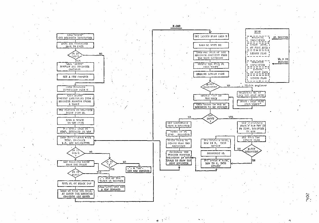
1I:1.ISI:x111 J.XaN 3111 1•1011S 01 31UVJ.
-1► lV1U NI str..tsiiXRi UNitu)I!S 1Gl7.NI(.1
;•11U. .I.N' IU:1I t:IN(
UN
1.
3'11(Ci :1111 I:0111 AI!1NM IurlRrITl J:to
SI.L
UN
LNVi' 03 M21N J3J •..7i.9u
(JNVINTiU0 MIN V 1,19 1 \V,.1.rin7C).19r3
I(UM i:4U Si :AMU
AlIt 'III (H 1
li L%VS $UV SlN3INO0 1)AISI!Xf1I 3111 IL" Din LV '11'1JV 'MI ILLY,i :111 (IV07
101 N3V1S NO '111 3.11S
Q\
11.LU1 1S i\ :IISi 1:1J ''.11 .1\ lK1 ML'IU
t aa; IMa.x 11'1-91 •
039N171;) 311 Ul L1'1.L9IJ311 .11
9:11 0.1„.1011.'10„11r) jV;)
11111. (I T. .. .11.1.Lt 11)
t
JVla IU.1INrI ;•1N111V)3
.VII :1J_ilL 11111 1.,11.1.110
:dU ILLI!i 'III 011111
U 0.11:1 JVId 111.11N111 11111
UN
1LIONN.;11V.) 11111 .tN'IN J 1.I11Ill
;NOMV.10 :1115 GILL 1:0111 S.I.tiiJSOJ 1L7.1S1KR1
11111. .10 'i 1.21 :1:\0 tI VII•I
J1'13 ILLJ.' 1'1
1 1':11IV .Lt1S dU I I •i100V=1 1
1 t:i i:111.\Al 11 I 21.31NIIl3 I 1E1 1-11Y-11.1 ! 11 +''rn
Jt'Li 7l11).`Ei
1 1311V :L1VS 10 I 'row; 1171!211 1
r 2111 { 11.' 7u 12INIUd la I 17sI!iH1 1
IL VIII
O1NI Yo:l `S1111 R Ird!11N1 l!1
'111 1GLIZ111:X1U
SIC
1J1'11 ILI.a\;C1 11.1,01 d:i11 - I
1■ 11 X1 LOI.S1OaII •.11(:11 NI
.LI..L(L1 (INV ,t1. I:O111 1frIIV\11,:0 ,11411
AtiU1:11: 01N1 'U NL ) ox
`81.Ill R 1CI.I.II 1,11
ON. \.L1 SI.
1125.1 US 40111 1111:)L7I1'H.1'JI1r 1111')3
1)31dl1Sl1)L lI;l1y11.iU 320 ,.11).111!1.; 1'110
N111 \1 0:11.51L111 'dRIJ. NI :111") 'i'.IV.LS .11.1
'111 Ill.NI .I21.L2l IEIIi'i UIjn UI 1111':1'7.! LILT
L 3111V.L V
JNIS,I SS: (10V IL1isi i:111 V (1 _NI 121..11 X1111 12111.11i0:)
.W1f1;1.'1'1V"I 1
J U.I_\l lIlI:1.17\Iai In lc1!rii! 11111I
(.1N11N1:11;) M3i1 V J:IJ
1 SJ,NI L\U:)
1r1151!1121 'l11' ALi5isiu
51.t
11411I 1:1'1111 13!) •21.1 12a7.ti l ;1ii '.I1~I1
If 1.1,S 11l1.V1 l l.)'IV (1VII'!
UI ,.I 111L 01 213y..IS V 01111
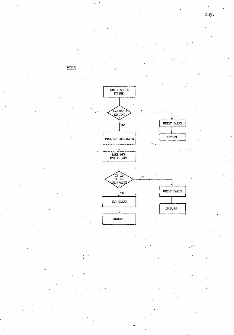
I1WAK
205:
.8

SUBROUTINES
FROM B INTO C
• NOTE: Subroutine "Convert to Binary" accept .hexadecimal numbers and converts these to binary,
YES -
ECHO LOAD B WITH C
IS I1 YES "ESC"
NO 1
>lo E ri INTO- C i0 LC110 - REfUILN
CALL ' ('0 4
TS 1 '1' ''(lt,
( NO
ltEsTORE
Otn'r`i%i ('IL1IllCTl7t
1.1)A0 A WI'111 "CH" CODE
itla'i1tx
CHM
E.(11()
LESS 'ElAN TIN
9
NO
RETURN
CNVF
EC111) "LP" AS WET.L
LOAD A WITH C
SUBtRAcT UUOU FOR. • ZERO IRoM IT
A, B, C, 1), E OR F SUBTRACT ANOTII)"d. 7
F O>I IT
GET CONSOLE STATUS
TR1Ns;II1T1at READY NO
YES
ROVE CIL1)L1CTiit FROM C INTO A
CI• CO •
GET STATUS OF CONSOLE

4
CALL CI
1 REHOVE PAIIITY BIT
GET ET I
SAVE HL IN I l STACK
CLEAR HI, AND E
111T DELIMITER IVALID DICIT)
DELIMIT ILIt WAS THE FIRST INPUT
CALL HETCII
G1l.l.' VALDL` Tl CHL•'Cli TUE
VALIDITY OF D£LIMITTER
NO
YES
IN • D-REIN -4 VALID
~•T IPUT ADDR INPUT TN BC-REGISTETZ~ JT?iP.:it)
ERROR
RESTORE ~CoNVERT TO slr+Alir
ORTG1NA i. IlL
I GET "E" FLAG ELO.AD E WITH Doi
NI_ SHIFT LEFT 3 PLACES ZERO''
NI)
No RESET CARRY TO SIGNAL ERROR
111'I UPPER B1'I'i: IF INIIJ'I' IN'l1A LOAD E wITH 20D
a GET BLT 7 MGR ROTAECARR' ; IT INTO BIT 7
OF UPPER E'rrF REIUR.N _
. CLEAR B.
f PTT A I
INTO C PLACE UPPER BYTE I'NTR S-REGISTER
I AEO sc TO Ht. SET Mani AND RETURN L_.__
RETURN
FRET • I
GETCII
PUT CODE FOR "E" INTO .C-REGISTER
PUT CIL1ItACTIM m"TO C-REGISTER
SET CARRY
CO»IPLEMENT IT
RETURN
CARR BIT IS ZERO?
YES WIT)V l' SIT 7 11,.A I NTO CARR
i* I)V1; A IN ID C AND ECHO TT

U)
C
%
C-REGISTFR
208.
SAVE A1N'~III
"j
SAVE 111, PAIR
LNCIIEMFNT ill,

i
LOAD E WITH 2
PiJ. it A INT'O1 STACK
ROTATE A 3 PIACES RIGITT
DECRD.IINT E
NO
YES
NEXT j 3I.TS ARE READY TO GO
STACK . —J
A' NOW CONTAINS . TILE M.S. BITS
TN BITS 0-2
LOAD E WITH 3
CLEAR ALL BITs IN 'A' I (CRrr BITS 0-2
Ft A INrO C
GALL "L' AL" TO CONVERT Nl NBER LNTO ITS ASCII
CODE
GET LE\'G'I1T FLAG
16-BIT RECISTIR
DT:CRINI:NT DL7-1
OUT1'I "1' LOWER S-BIT ADDR. TN ill'.,
8-S-IT Tay; I S.1" EDI
N. \O .
YES
DECI?IMENT E
YES
ALL BITS Al E I'1tINTED OUT IN OCTAL •
RESTORE DE AND HL
RETURN
LOAD III, IslTll 'ILII1 AUDIO. DI 4 IITALI'
01:1 1911NT SYMBOL J 11101 TI11; TABLE
YES TS I 711101?
ND
THEN 'LI11: !.N1). OF THE TABLE
CALL • CIL0UT ' AND RETURN
ECII0 CHARACTER FOL,IAIWI'.D BY
"=" SIGN
IN(:1IkII.NT III, T(1 SHOW THE 1.01a:R ,ADDR. OF SAVE
LOCATION
SAVE ADDRESS IN10 DE. (I) IS CIINNIIN FOR ALT, (IF THIN)
REGDS
INCR1•:UIN I' 111. 'TO Sf1Oli I,TNGT11 I'l_AG
WTI 'UT C) IN1.1•NN )' OP SAVE ADDRESS
NMOCT SAVE 'IL
rRVAT. LOAD Ill. li 11'11 AI,I H(. I)F CODE TABLE (DIGTB)
CLI AIt IJ
ADI) IIC 11) Ill, (c AIRE'DY SI•711
FI'.l'f"11 CIL1IL\C17:R l 010ih NE.,;( my SIIIo.i\ By HI, 4 ?iC
RETURN
SAVE DE
• I SAVL ACC. ANI) FLAGS
ECHO OUT 'I11E 3 BITS (TN OCTAL FORII
RESET CARRY I
RESTORE 'A'F101>1 STACK TO GET. WE NEXT3 BITS

` LOAD EL WEE
I I E JrrA3 ADDRESS RCADR
RETURN
ARGUMENT r USED CHARACTER I120?1 TABLE WITH INPUT
CI IA RA CTIM
I)IS4IllE INT Eli111;PT WHITE RESTORING
SI:P
1 JIES11 ii1: ,lI L i ! SAVED REGIF'I'FIFS It
RESTORE HI, I'Ru1>i ITS SIVE LOCATION
LOAD DG WITH 000 001
GI.T REGISTER 'i IDLITIFIER FiIOt
THE TABLE 1
YES IS IT
THEN ILLEGAL 1 CO;IPARE; C CALL SIR OR
BOTH • YES
NO
ADD PL TO HL TO ADVANCE
POINTER BY 3
j
INCRI?R.tiT IIL TO SHOW THE ADDRESS OF • SAVE LOCATION
SAVE THIS ADDRESS IN BC
fRETURN TO LUCATIO`
SITOWN BY PC
MON 1Ton SI' TO START OF STACK
RESTORE 1': ER SI' 11DM ITS SAVE LIICATTD\
r 9iI'•Iis1.0 ic U\ 'II1I' OF 111E STACK FOR RET.
A DI 0 ESS
1
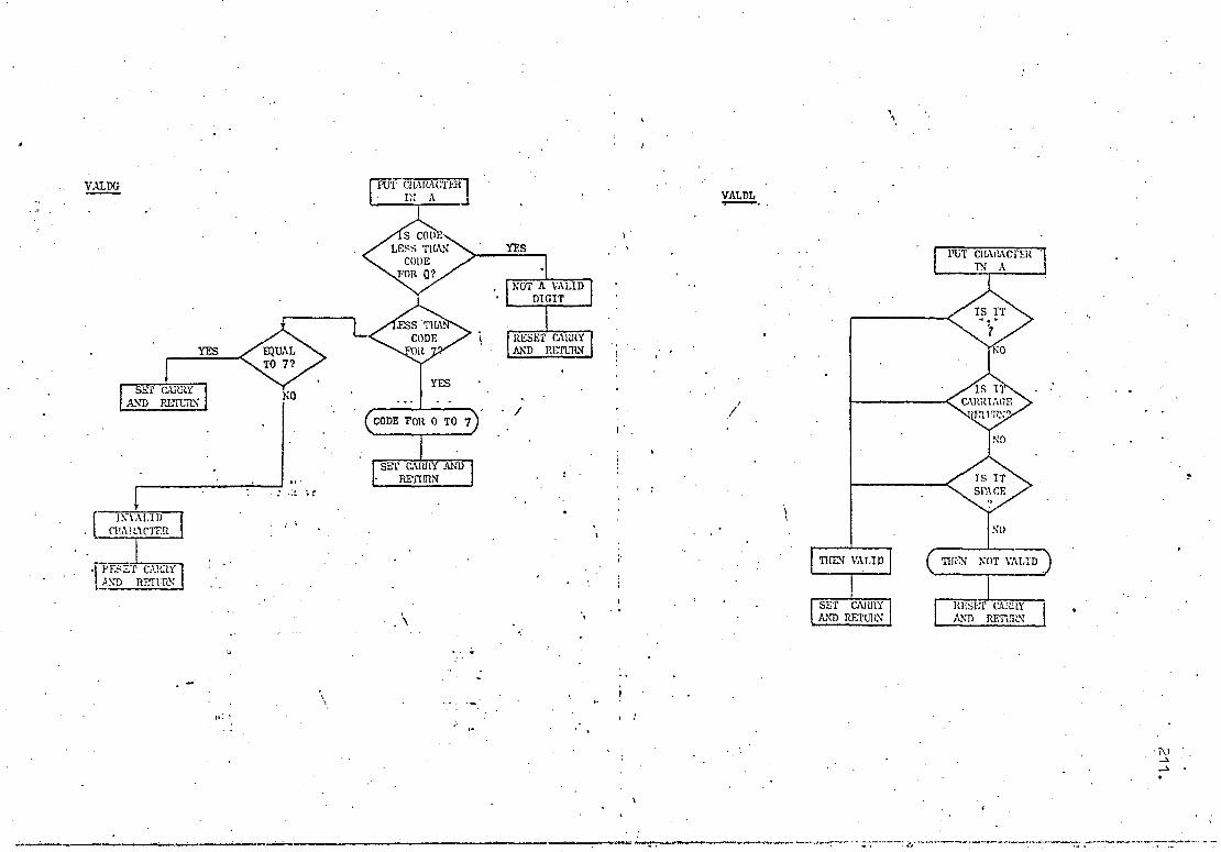
FP—Ur cI TER iARAc • • IN A 1
S COD LESS THAN CODE FOR 0?
VALDG
NOT A VALID DIGIT
YES
SET CARRY AND RETURN
EQUAL TO 7? NO
SS TI CODE It
SEI CARRY AND • RETURN
YES
YES
7 i\1'ALID . (1fAi ACTER
I .1 RESET CltRY1 AND RETURN
VALDL
SET CAI titY AND RETURN Ri:st::r CARRY AND RETISLN
• •

R TAB: Table of Register Information.
Register Identifier
L-addr of save area
Length flag
MONITOR TABLES
Sign-On: Contains CR, LF, INPUT COMMAND, CR, LF.
CADR: 'Address of Commands in two bytes.
X,-CMD
}scm
M-CMD
I-CMD
G-CMD
D-CMD
CTAB: Table of Valid Command Character.
212.
Code for D Code for G Code for I Code for M Code for S Code for X
DIGTB: Table of Print Values of Hex. Digits.
Code for 0 Code fōr 1
Code for 9 Code for A
Code for F
Register Identifier L-addr of save area
Length flag
A B C D E F H L M P S 0 End of Table Marker

APPENDIX
A3.1 Strowger System
The term "Strowger" is used here to describe all systems
derived directly from Strowger's original idea, such as the standard
2000-type equipment of the British Post Office.
A substantial part of all exchanges consist of the
following:
(i)
Subscribers' Uniselectors or Linefinders, which are
switches by which subscribers can obtain access to a common
group of first selectors. Line finders are only economical in
exchanges with a fairly log* calling rate, therefore they are
not as commonly used as uniselectors.
First, second and sometimes third Group Selectors for
switching a call through to the required group of final
selectors. All group selectors are substantially the same,
irrespective of their position in the switching train.
Final Selectors, which give access direct to the
required subscriber's line. There are several different types
of final selectors for various Private Branch Exchanges (P.B.X.)
and automatic exchanges.
(iv) Auto-to-Auto relay•sets on the outgoing junctions to
a distant automatic exchange.
213.

214.
(i) Subscriber's Uniselector Circuit:
Fig. A3.1 shows a subscriber's uniselector circuit for use
in exchanges with positive battery metering Refs. 9, 7).
The caller forms a loop for L-relay by lifting his receiver.
Contact L2 engages the line on the final selector multiple and starts
the uniselector driving magnet to hunt for a free selector. The
K-relay operates in series with the driving magnet battery when the
P-wiper rests on a non-earthed P-wire of a free selector. Relay L
then releases after a lag of 100 ms during which a holding earth is
returned through the P-wire of the seized selector to keep the
K-relay operated. Contact K4 prepares the circuit for the meter Co-
operate with a 50 V positive battery signal returned on the P-wire
when the caller answers the call.
On an incoming call, the application of earth to the P-wire
by the final selector causes relay K to operate (L is not operated)
which at K1 and K2 removes the bridging apparatus from the speaking
pair.
(ii) Group Selectors:
As was mentioned, the uniselector is followed by a series
of group selectors (Ref. 9). Fig. A3.2 shows a simplified diagram
of a 2000-type 100-outlet group selector. The A-relay operates to
the subscriber loop when the selector is seized by the preceding
group - or uniselector. Dial tone is then returned to the caller,
when appropriate, while the other contacts of the B-relay return
guarding earth to the preceding circuit as well as providing a closed

215.
loop to operate relay C. The vertical magnet, V, does not operate
owing to the insufficient current available to it.
Relay A is released during each break impulse from the dial
and at Al repeats the impulses to the vertical magnet. The latter
steps the wipers into the chosen bank and operates the off-normal
springs (N). Contact N1 closes and relay H operates. The wipers
then rotate horizontally to search for and seize the first free outlet
in the level.
The operation of rotary magnet, which was made possible
when relay C was released at the end of the dial impulses, operates
NR springs and opens interrupt spring R1 once for each horizontal
step of the wipers. Ri interrupts the holding circuit for H-relay
so that it releases when the P-wiper moves to the first free outlet
and fails to provide a holding earth for H-relay. Under this
condition the operation of relay C reoperates relay H which holds
relay C through 115, Cl and NR4.
If all outlets in the level are engaged, the selector
steps to the 11th rotary contact, operates an overflow meter, and
returns busy tone by operating S contacts. On termination of call ,
H-relay releases, as the P-wire earth is removed, and this initiates
the self-drive rotation of the rotary magnet to home position.
When the volume of traffic is reasonably large, considerable
economies can be effected by providing group selectors with an
availability of 20 outlets per level. Such selectors are known as
200-outlet group selectors and are fundamentally similar to the
circuit already described. These selectors have an additional testing
relay which enables the doubling of the negative, positive and

216.
P.banks. The following group selectors (i.e. N+1th
group selectors)
are fully available to all the 200 outlets of the preceding group
selector (i.e. the Nth group selector). However, if the (N+1)th
group selector is a 200-outlet final selector, then the outlets of
the Nth group selector are connected such that even and odd hundreds
digits can be distinguished in the final selector before the last
two digits are received. This arrangement is discussed in the
following section.
(iii) Final Selector:
The 100-line final selector is very rarely used and in all
but special circumstances 200-outlet selectors are employed.
However, the principle of the operation, shown in Fig. Ā3.3, remains
unchanged (Ref. 9).
Relay A is the impulse-accepting relay as well as the "
transmission bridge impedance element for the calling subscriber.
Exchanges operating under a common control scheme often use two
A-relays so that the control equipment with its A-relay can be
released as soon as a tone is returned to the caller through the
second A-relay in the selector unit.
The vertical magnet steps the wipers of the final selector
under the influence of current pulses through the 5Q holding circuit
of the C-relay which releases at the end of current pulses as its
700Q winding remains shorted through Ni. The operation of E relay,
made possible when N1 contact closed after the first vertical step,
redirects the second train of dial impulses to the rotary magnet
which rotates the wipers to the selected output, also operates all
NR contacts.

217.
The H relay now tests the called subscriber. An earth
potential on the p-wire of the busy subscriber prevents this relay
from operation, consequently relay G operates some 300 ms later
when relay E releases and busy tone is returned to caller. If the
called subscriber, on the other hand, is free, the operation of
relay H through the potential via the K-relay of the subscriber's
line circuit, closes the circuit for relay J which, at J3 and J1,
connects ringing tone and ringing current to the subscribers.
Relay F operates to the D.C. loop caused by the called
subscriber's answer. Subsequently relay D operates, reversing the
caller's line for supervisory condition, also at D1 reoperates
relay E which, at E4, sends a positive battery pulse to the caller's
meter. This pulse has a duration equal to the release lag of relay J
which removes the positive potential at J2.
In this circuit arrangement only the caller can initiate
the release of the whole circuit. If he does not clear when the
called party has done so, a supervisory alarm is given after a short
delay.
The ballast resistor (barretter) in the called circuit
presents a higher resistance to larger currents than it does to small
currents. This enables a low resistance D relay to be used to give
adequate current for the carbon microphones on long lines without
permitting excessive currents on short lines.
The arrangement for the 200-outlet final selector allows
it to receive a discriminatory signal from the preceding group
selector to switch to either the odd or the even set of wipers as

218. •
required. All the outlets from the even levels of the last group
selector (i.e. 20 outlets from each of the 5 even levels) pass through
a wiper switch relay (WS), shown in Fig. A3.4, before they are
extended to the final selectors. A D.C. loop condition on these
outlets selects one of the two groups of final wipers.
(iv) Auto-Auto Relay Set:
On outgoing junction calls, the last group selector routes
the call to the relay set which repeats the dial impulses for the
distant automatic exchange and allows the call set up to continue.
As the circuit details would not be relevant to this thesis, the
reader is referred to Atkinson (Ref. 9) for any further information.
A3.2 Crossbar System
The TXK1 local exchange is a modern register-controlled
crossbar system designed for non-director exchange operation. The
system, together with its director-exchange version TXK3, amounts
to 4% of total exchanges in the U.K. (Ref. 5) . Each of the crossbar
switches consists of a number of multi-contact relays called bridges.
A complete bridge has several springsets which have to be selected
before they can be successfully actuated (Ref. 15). The size of
the springsets depends upon the outlet capacity of the switch and
the number of wires per circuit, i.e. P, +, -, etc. The select
magnets operate within 10 to 22 ms of receiving the operate signal
and have a release lag of 5 to 9 ms. The operation and release time
of the bridge magnets are within 15-24 ms and 5-14 ms respectively
(Ref. 28): As the routing of a call is performed by the markers, the
operating speed of the cross-points is not critical.

(i) Local Calls:
The basic operation of a local call setup is shoran in Fig.
43.5. The calling subscriber finds its way into Distributor Switch B
(DSB) through its line circuit which signals the line marker. The
distributor serves 500 lines for outgoing and incoming calls. and the
exchange is built for a maximum of 60 distributors. INarkers, initiated
in the line circuit, are extended to all free DSA's, each of which
attempts to seize a free Local Transmission Relay Group (LTRG) with
a free first choice or second choice register associated with it.
Meath hile the line marker prepares the distributor►s cross—points
for operation. A hold signal returned from the seized register
operates the cross—points in the DSB and one of many possible marked
DSA's and extends the caller line to the register where dial tone is
returned (Fig. A3.6). The line marker is now free to deal with other
calls.
Dial impulses are received by the register's impulse
reception circuit and are counted by the pulse counter circuit and
stored in the form of a pattern of operated relays Ref. 15). Number
Unobtainable tone may be returned by the register, if required, at
this stage. When sufficient digits have been stored to enable
routing of the call, application is made to associate a Router
Control(R/C) to the register. This delay in application for the .R/C
ensures efficient use of that device, which has to accomplish its
task within 6 ms before the connection task is passed to the second
R/C for a second and final attempt. The information on the call is
passed to the router for processing. The R/C then sets up a path
to a line marker associated with the distributor in which the called
subscriber is located. A marking earth is also sent, through LTRG,

220.
to prime all Router Switch A's in anticipation of a path to the
called subscriber.
The state of the called line is then investigated when the
RA extends a marking earth through the line marker of the
objective distributor to prime the DSB in which the called number
was located. Should the subscriber be engaged, the operated K-relay
in the subscriber's line circuit diverts the interrogation earth
back through the line marker into the R/C which then clears down and
busy tone is returned from the LTRG. If the called line is free,
earth marks will be sent back from the called side DSB to find the
specific LTRG. In short, the caller line "hunts" for a free LTRG
but the called line "finds" it. On receipt of the earth mark, the
primed RSA operates its cross-points and extends the holding earth
to operate all the cross-points back to the called subscriber. The
WC and the line marker then clear, leaving the register and the
LTRG to send ringing tone and ringing current to the subscribers.
As the register proceeds to clear, the LTRG takes over and returns
ringing tone to the caller.
On called subscriber's answer, the LTRG provides the
transmission bridge and reverses the called line potential. Both
sides can release the equipment by replacing the handset. However,
if the called line clears and the caller does not, the K relay in
the called subscriber's side remains operated and the line, while
not receiving any signal, remains busy.
Fig. A3.7 shows the elements of a link between two subscribers
receiving ringing tone and ringing current (relays are shown under
their normal condition) before the register clears. On answer, DT

relay operates to reverse the called line potential and closes the
path (not shown) for a multiphase pulse supply for the application
of a periodic meter pulse to the incoming P-wire. Metering starts
some 250 ms after the operation of DT relay, the lag being due to
the release lag of other relays involved.
(ii) Junction Calls:
(a) Outgoing: On a junction call, the code discrimination
process in the register results in the concurrent seizure of a coder
and R/C as soon as a particular exchange code is recognized (Ref. 15).
Once the exchange is known, the End of Dialling (EOD) can be foreseen
as each exchange deals with 4, 5 or 6 digit numbers. In the cases
'where such information is not readily known, usually the 4th dialled
number is considered the last unless the next pulse arrives within
4 seconds after the inter-train pause of about 500 ms to 800 ms.
Therefore, in such a case the subscriber behaviour in dialling the
required number can affect the efficiency of the exchange operation.
Having checked the information received from the coder, the router
control extends marks to the Junction Groups (common to. all Junction
Markers) and to the appropriate Junction Marker. Connection is then
completed, as before, to the outgoing junction circuit (Fig. A3.8).
To seize the distant equipment terminating the specified
junction, the latter is shorted via 200Q resistance to operate the
relays in the distant exchange. The R/C then releases while the
register seizes a "Sender" to transmit the stored information at
1;0 P.P.S. with 800 ms inter-digit pause (IDP) for Strow er-type or
500 ms IDP for exchanges equipped with storage facilities.
221.

222.
(b) Incoming Call: The incoming call is treated in a very
similar mariner to a local call. Each incoming junction is
permanently connected to an Incoming Transmission Relay Group (ITRG)
which has facilities to store the first incoming digit while an
Incoming Register is being seized through a Register Connector.
As can be seen from Fig. A3.9, the caller line is first connected to
A-relay which returns the appropriate tone. The cycle of the tone
continues through the LS relay when the circuit is ready to release
the register and its associated circuits. The transmission bridge
in the callers exchange is by-passed in this case; however, if the
incoming exchange is a large Private Branch Exchange with no
transmission bridge, this circuit will be provided as in a local
call.

-,
To Catler
mulgple final selectors
-+
p
JL•
... __ I o
_._".- -.-
, \
/
I
K _}-o: __ ~,~-------------------------- 0 , ~
-UDfNL T.
II:'~oOl . K
o t~
I
o q, 0°
~Kk~ ___________________ +_}··: ____ __ r 0
o o /) .
Uniselector Circuit , (Strovlger Exchange)
p
-.. . . _. . -, . --- .. ,
to selectors
10 I':' Vl .

P 1M1~tr¢
N •
Fig. A3.2 Simplified Diagram of a Group Selector in Strowger Exchange
j •
•
• t • .
C3
INT• BAT - EARTH
0i1U iGNE
• • •
• •
0 0
0
1,6
•
I
BUSY-TONE

A D
_ 1 H ti
int.ring r
g' el ] tone
; ] busy 41 L G,
tone 1 3 • IF
Ec
,_.\ • .N. 1 Hi,. Bi Jl
E.G .l
p N2. A
3
• int.ring.
R
Fig. A3.3 Simplified Diagram of a 100 Outlet Final. Selector(Strowger Exch.)
Hs
200
• ring.ret. batt.
F,
L barrettcr

+ (odd)
E
+ {even}
, .1
A
II-~---~--F 1 ..
I
t
O-Rela.y
~ I • I
/
II---L---'r I
I
H
Fig~ A304
200 0 I utle.1. F·
::IH--t~ ---C) -, -4' I ,
I
ws ,
- {even}
- (odd)
--+
,( u J.nal S ! Strowger E elector I xchange) F-Rela y. p-{ 0 dd )
• I "". ';f " ..
• • .... " I ... ·0
Q .--.. .. • .. ..
.. . .
c-
•
., "," ..
., " • iii Q-
tI e
0111 rv
Iv 0'\ .

DSB DSB
REC• ALLOTTER REGISTER
ROUTER . CONTR.
LINE MARKER LINE MARKER
LTR G
Fig. A3.5 Basic Operation of a TXI I System
(D=Sequence of Operation

OS$. OSA. R EG. LTRG.
sequence of n = operation
register aLCotter Fig. P3.6
N
line marker

LR
LR ~
(—
LR T. K
D SB
'. sw T I ring
re t.
DT
A TC
F N
LTRG u L J
TC int ring•
ORF
SW
busy NU,ri n g. tone
.
BM
TC
. DSA
LR l P,
i
LR
RS B DSA DSB
Notel: SW relay is operated if the transmission bridge is to be bypassed such as in tandem exchange
Note2: TC relay is operated when the path is extended from the called subscriber to LTRG,and is disconnected when F-relay operates:
RSA
L REGISTER
1 11A 1
ringing tone
Fig. A3.7
TXK1 Crossbar Exchange

t
junction group
LTRG RSA RSB
TC
C!G junction
B sub's loop .
X—"
B ■s w r--'
sw
0I6 J!IMD!1 GCT.
1B
junction marker
A
REG.
sw
Fig, A3,8
Junction Call (Outgoing) TXKI System -hw
~}~i------- 200 RIC

UC TRG
RSA
ring t.
. LS
ring_ [one
TL (1 f F3 SW
B = BT
ALS B
storage for
first digit
Fig, A309
Junction Call (Incoming), TXKI System

232.
APPENDIX (4)
SUPERVISORY TONES:
Supervisory tones are connected to the exchange termination
in a balanced mode in order to minimise cross-talk in the exchange
and in the cable. Most of the standard tones consist of a 400 Hz tone
which is interrupted at regular and pre-defined intervals. The choice
of the frequency and the minimum duration of the tone was made to suit
the characteristics of the human ear. The human ear does not fully
appreciate the true power in the sound which is shorter than 200 ms.
Further, it is known that a tone of 400 Hz at an acceptable power
gives a noticeable, but undisturbing, annoyance when experienced by
the human ear.
The main standard B.P.O. tones are mentioned below and their
differences, if any, from the supervisory tones provided by the
College internal exchange are pointed out whenever appropriate see
Ref. 52 for other relevant information) .
(i) Dial Tone: Dial tone is transmitted to a calling subscriber -
to indicate that dialling may commence. It consists of a continuous
tone of 50 pulses per second (Fig. A4.1) and when heard in the
telephone receiver the tone produces a distinctive uninterrupted
purring sound.
(ii) Busy Tone (Engaged Tone Busy tone is applied to the
callerts line whenever the called line is busy. The B.P.O. uses a
400 Hz tone which is interrupted for 0.375 sec. every 0.75 sec. The
College internal exchange uses the same frequency interrupted at 0.75
sec. every 1,5 sec. Fig. 4A.2 shows the waveform of this tone.

233.
(iii) Equipment Engaged Tone: Equipment engaged tone is returned
to a subscriber during the setting up of a call if the call is .
prevented from reaching its destination by congestion within the
system. (This tone is replaced by Busy Tone in the College internal
exchange.)
The tone has a frequency of 400 Hz and has the following
sequence:
0.4 sec. ON
0.35 sec. OFF
0.225 sec. ON
0.525 sec. OFF
The level of the tone during the 0.4 sec. period is 6 dB •
lower than the level during the 0.225 sec. period (Fig. A4.3).
(iv) Number Unobtainable Tone (NU Tone): The Number Unobtainable
tone consists of a continuous 400 Hz tone (Fig. A4.4) and is returned
to the caller if a spare code or number is dialled, if the called
party is parked or is out of service, and if the call fails due to
the exchange misoperation or malfunction.
(v) Ringing Tone: The standard B.P.O. ringing tone sounds
similar 'co that obtained when two frequencies of 400 Hz and 450'Hz at
approximately the same level are connected simultaneously. It is
returned to the subscriber when the call has been successfully set up
and the calling signal is applied to the called termination.
The tone is initially applied for a period of 0.35 sec.
followed by 0.22 sec. silent period and starts again at any point in

234.
the following cycle:
0.4 sec. ON
0.2 esec. OFF
0.4 sec. ON
2.0 sec. OFF
The College internal exchange uses a 400 Hz tone which
follows the above cadence (Fig. A4.5).
The called party receives a ringing current supply which also
follows the same pattern.
(vi) Pay Tone: Pay tone is applied on a call from a pay-on-answer
coinbox when the call has been answered. The tone, which is heard
by both sides, consists of a 400 Hz tone interrupted at 0.125 sec.
every 0.25 sec.
TOLERANCES:
The tolerances specified for the various tones differ
according to the generating source of the tone. In general an upper
limit of +5% and a lower limit of -13% are considered acceptable
for the frequencies of various tones.
The timing accuracy of the tones (cadences) are normally
kept to within ±40% of the nominal value. Under-the most adverse
conditions the timing accuracy is kept within +16% and -20%.

Fig. 1 k.1
Dial Tone
P our
_Tc r -
CN
J
Fig. Al 2
Busy Tone
u
4 S'-4 r0.35} 0.215-525
Fig. A4a5
Equipment Engaged Tone
p r . „ J
Fig. Al olr
Number Unobtainable Tone
z. o S,t, ,.1 Fig. Ak.5
Ringing Tone
1; ~~~~';[ --'~ RJq .lr--
qp
J.

236.
APPENDIX (5)
The flowcharts of the Teletraffic Monitoring Program
described in this thesis and details of various subroutines are
gathered
in this appendix.
The following parameters are used in the program:
1. Current Time (CRTM): The content of a 16-bit counter, counting
the number of timing pulses.
2. Current Line Address:
The content of an 8-bit RAM showing the (cRLA.)
address of the line being serviced by
the microprocessor.
3. Current Block (CRBLK): The content of two bytes of RAM showing
the address of the block which holds the
information on the line being serviced
by the microprocessor.
4. Address of First Block: Two bytes of RAM set to show the address (ADR BLK1)
of the RAM section which is divided into
blocks of 48 storage locations to be
allocated to active lines.
5. Number of monitored:
An 8-bit counter to be set to show the lines (N)
number of active lines which the processor
can attempt to monitor.
6. Address of Busy Table: A two-byte address showing the section (B.TBL.ADR)
of RAM allocated to the Busy Table.
7. Address of Tone Table: A two-byte address showing the section (T.TBL.ADR)
of RAM allocated to the Tone Table.

237...
8. Overflow Flag:(OVFLOW): An 8-bit flag which is set by the timing
pulse and is cleared at the end of the
program.
9. Start Line Address: (STLA)
A byte of RAM containing the identification
address of the first line connected to the
microcomputer.
10. Line Flag Address: A two-byte address shoving the section of (LF.ADR)
RM allocated to the Line Flag bytes.
11. Line Group Flag Address: A two-byte address showing the section (LGF.ADR)
of RAM allocated to the line group flag
bytes.
12. Dump Address (DUMP.ADR): A two-byte address showing the section
of RAM to be used as a buffer for unloading
blocks of information.
13. Register Save: Ten bytes of RAM to be used for temporary
saving of the registers and the stack
pointer.

YES PENDIN OPERATION
IN PREVIOUS CYCLE? iSET 0 a LOW FLAG
TO SHOW THS START OF NEW CYCLE NO
UPDATE TIME INFORMATION I.E. INCREMENT CRTM
START OF THE PROGRAM
RESET OVERFLOW FLAG
RETURN TO THE INTERRUPTED PROGRAM
INITIALIZE SP
INPUT NEW DATA FOR REGISTERED ACTIVE LINES I.E. CAL BUSY SERV)
INPUT NEW DATA FOR LATCHED LINES
I.E. CAL (TONE SERV)
SET HL TO SHOW BUSY TABLE
PICK AN ENTRY IN THE TABLE I.E. CAT, (SEARCH)
ANALYSE DATA FOR THE PICKED LINE
I.E. CAL ANALYSE
FIND LGF USED BY HUNT I.E. H..LGF
238.
Teletraffic Monitoring Program:
CHECK INTERRUPT ])
UPDATE LGF USED BY HUNT

CLEAR OVERFLOW FLAG
TRANSFER TO START OF PROGRAM
' 239. .
T NEW VERSION OF THE LGF
ROTA'" E IT n TIMES S TO CORRESPOND WITH NUMBER OF ROTATIONS ALREADY CARRIED OUT ON Ii . LGF
REPLACE H.LGF WITH ROTATED LGF
READY TO CALL HUNT
NO
HUNT FOR A NEW ACTIVE LINE, I.E. CAL (HUNT)
HALT.
NEW ACTIVE LINE FOUND
SEARCH FOR A FREE BLOCK
ENTER INFORMATION IN THE BLOCK
ENTER LINE ADDRESS AND THE BLOCK ADDRESS INTO
BUSY TABLE I.E. CAT,J SEP . TBL)
SET THE LINE FLAG BIT

2j40.
Subroutine HUNT:
This subroutine tests the state of non-registered lines
to find a new active line. When the line is found, the subroutine
sets carry flag and returns. If a fresh program cycle interrupts
the subroutine, unfinished operations are terminated before the
program cycle is restarted.
Parameters used by the subroutine are:
Hunt's Line Address (H.LA): A byte of memory which is used to store
the address of the scanned line.
Hunt's Line Group Flag (H.LGF): This location stores the rotated version
of the line group flag bytes such that bit
zero of the stored byte corresponds to the
next group to be tested for scanning.
Hunt's Line Flag (H.LF): This location stores the rotated version
of the line flag bytes such that bit zero
of the stored byte corresponds to the next
line to be tested for scanning.
Counter K: An 8-bit counter which counts the number
of line flag bytes already scanned.
Counter R: . An 8-bit counter which counts the n uriber
of rotations performed on each byte of Line
Group Flags.
On return: Carry bit equal to 1 implies that a new active line has been registered:
Carry bit equal to 0 implies that last line has been scanned and no other active line is found.
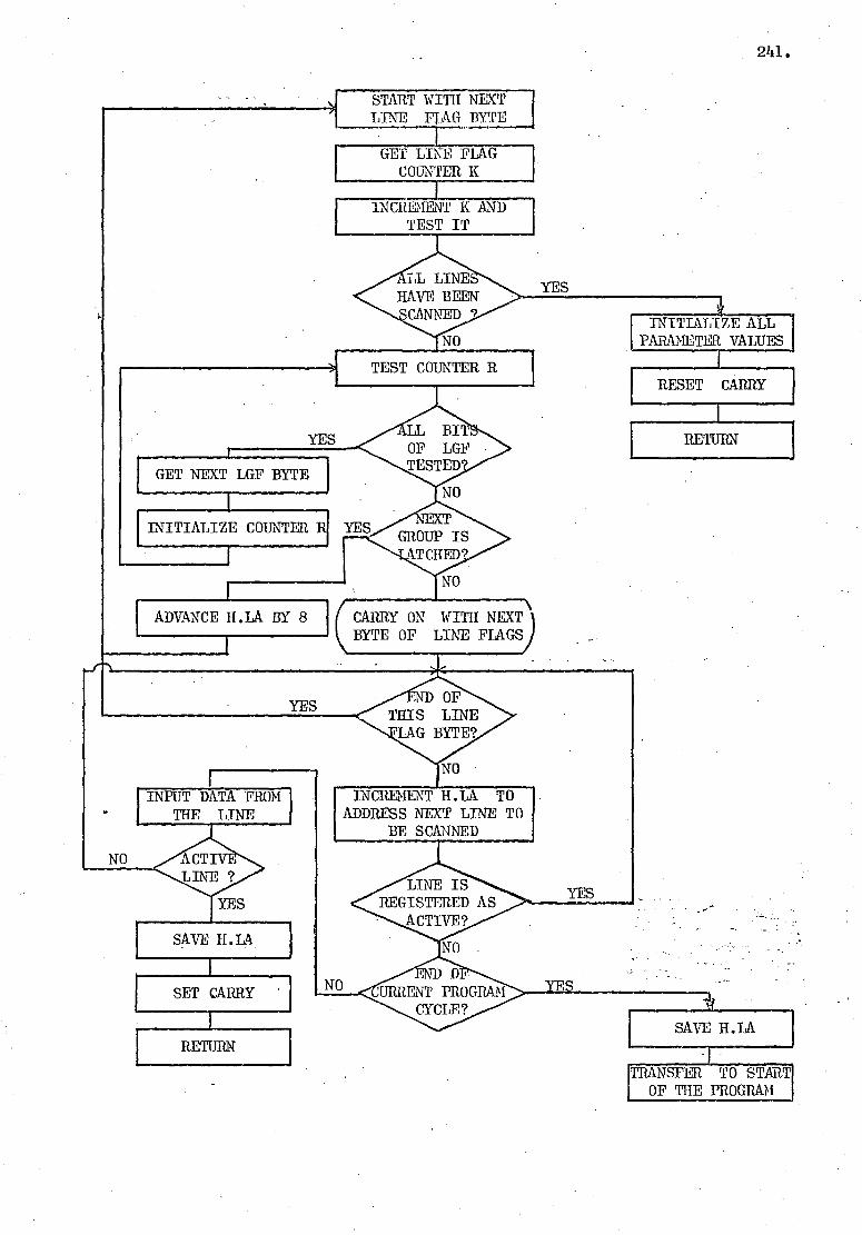
START WITiH NEXT LINE FLAG BYTE
GET LINE FLAG COUNTER K
INCREMENT K AND TEST IT
241.
INITIALIZE ALL PARAMETER VALUES r
YES
TEST COUN'1ER R RESET CARRY
YES RETURN
FGET NEXT LGF BYTE NO
T GROUP IS
TCIIEr
NO
INITIALIZE COUNTER R YES
7
NO
CARRY ON WITH NEXT) BYTE OF LINE FLAGS
INCRE[ENT II. LA TO ADDRESS NEXT LINE TO
BE SCANNED
ADVANCE H.LA BY 8
YES
INPUT DATA FROM THE LINE
YES
SAVE H.LA
SET CARRY
RETIJi N
TRANSFER TO START OF THE PROGRAM

242.
Subroutine DATA.REPL:
This subroutine replaces last data with the new data.
The new data is in Accumulator when the routine is called.
LOAD HL WITH ADDRESS OF LAST DATA
MORE NEL.' (DATA INTO MEMORY GIVEN BY HL
MOVE INT. COUNT INTO NEXT TWO MEMORY
LOCATIONS
RETURN 1
Subroutine TIM.DIF:
TIM.DIF1: Finds the difference between the registered time of old
data and the current time (Current Interrupt Count).
TIM.DIF2: Finds the difference between the 16-bit value given by
M and M+1 and the Current Interrupt Count.
On return: DE shows the difference; if Z=1 then either no difference.
or last time was zero.
TIM.DIF1
RETURN IF ZERO FLAG SET
LOAD HL WITH THE CURRENT INT. COUNT (CURRENT TIME)
SET DE TO DE = IIL-DE I.E. CAB DE HL)
RETURN
ADDRESS LAST DATA BY HL T.E. CAL LAST DATA
INCREMENT HL I.E. M, M+1 SHOW
LAST REGISTERED TIME
TIM.DIF2 .) L LOAD DE WITH THE CONTENT OF M AND
M+1, I.E. CAL (LDE x HL)

COMPLEMENT CARRY
FIND THE DURATION OF LAST DATA
I.F. CAL TIM.DIF1
DE CONTAINS THE DIl{FERENCE
SUBTRACT CY FROM D CY REMAINS RESET IF THE ONTENT OF DE IS BIGG THAN 'OR EQUAL TO 3
243.
Subroutine- V_AL.DATA:
This subroutine examines the validity of the last data
judged by its duration.
On return: Carry is set for a valid data.
Subroutine SQUASH:
This subroutine merges 4 bits of input data with the 11
least significant bits of the time registered for the data and produces
two bytes of information:
0 U DE must contain the 16 bits of timing information.
UAN must contain the required data.
DE contains the merged information; "A" contains the data.
SHIFT DATA IN A 3 PLACES TO LEST
CLEAR MOST SIGNIFICANT FIVE BITS OF D
OR D WITH A
PUT RESULT IN D
L RETURN
On Call:
On Return:

0 04
FIND ADDRESS OF APPROPRIATE BLOCK
FIND NEXT FREE LOCATION IN THE BLOCK
NO ~d
STORE A IN THE BLOCK
YES
r SET MOST SIGNIFICANT J BIT OF D
V FIND NEXT FREE
LOCATION - IN TIIE APPROPRIATE BLOCK
1
STORE DE IN THF; BLOCK
SET POINTER FOR NEXT FREE LOCATION IN THE BLOCK
RETURN
Subroutine DATA/TIME:
This subroutine stores data and the time registered for
the data in the appropriate block. The two pieces of information
are merged, if required, and a flag bit is also added.
ff O On Call: DE must contain the 16 bits of timing information.
N A must contain the required byte of data.
244.

245.
Subroutine PEtt.SAVE:
This subroutine (Permanent Save) stores the information in
the permanent saving part of the block (i.e. the Current Block at the
time of calling the subroutine). It examines the event counter to
decide on a particular sequence of operation.
Event Counter (Octal) Event Information to be saved
000 Off-Hook Marker, Line Address, 16 bits of current time.
001 Pre-dialling event 1 (Dial 4 bits of data + 11 bits of Tone) registered time.
002 Pre-dialling event 2 4 bits of data + 11 bits of (Start Dialling). registered time.
003 Dialled Digit. It bits digit counter + 11 bits of start time.
004 First indication of tone. Marker; two 16-bit counters; one 8-bit counter.
005 Tone on the line. Number of tone-on samples; half-second intervals.
006 Answer. Marker; 16 bits of current time.
007 Clear. Clear time.
010 Line being called. Two bytes of markers after first pre-dialling event.

000
2
LOAD DE WITH CURRENT TIME
SET UP "PRELIMINARY
COUNTER"
r
SET POINTER TO THE NEXT FREE LOCATION IN THE BLOCK
RETURN
246. PER. SAVE:
FIND ADDRESS OF NEXT FREE LOCATION IN• THE CURRENT BLOCK
PUT EVENT COUNTER - INTO ACCUMULATOR
1 PUT CURRENT TIME
IN *AI
SAVE MAITSOER AND TIME, I.E. CAL (DATA/TIME)
LOAD ACCUMULATOR WITH LAST DATA
LOAD DE WITH TIME OF LAST DATA
SAVE DATA AND TIME IN PERMANENT SAVE
I.E. CALL (DATA/TIME)
RETURN
LOAD A WITH START NUMBER
PUT MARKER IN THE BLOCK
PUT LINE ADDRESS
IN THE BLOCK
PUT CURRENT TIME IN THE
BLOCK
others
010
006
FIRST INDICATION OF TONE
PUT MARKER IN ~A
ROUTE PROGRAM ACCORDIN TO TIīE EVENT COUNTER
PREPARE COUNTER FOR DIALLED DIGIT
CLEAR A
PUT ADDRESS OF NEXT FREE LOCATION OF BLOCK IN'HI;
CLEAR COUNTER FOR 4- SECOND PERIODS
SET UP "TOTAL COUNTER"
SET POINTER TO NEXT FREE LOCATION
IN THE BLOCK
RETURN
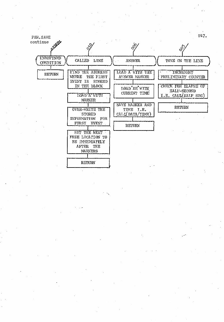
PER. SAVE continue
247.
TONE ON THE LINE
LOAD A WITH THE ANSWER MARKER
• INCREMENT PRELIMINARY COUNTER
_i FIND THE ADDRESS WHERE THE FIRST EVENT IS STORED IN THE BLOCK
LOAD I DE` WITH CURRENT TINE LOAD "A" WIITII
MARKER •1
OVER-WHITE THE STORED
INFORMATION FOR FIRST EVENT
J SAVE MARKER AND
TIME I.E. CAL L( DATA/TIME
RETURN
CHECK FOR ELAPSE OF HALF-SECOND
I.E. CALL HAI F SEC
RETURN
SET THE NEXT FREE LOCATION TO BE IMMEDIATELY AFTER THE
MARKERS
RETURN

OP LOOP INE9
PREPARE FOR ANSWER CHECK
CALL (ANSWER)
REPLACE LAST DATA WITH NEW DATA
RETURN
YES
NO
YES
CHECK TO SEE IF THE LINE IS CLEARED,
I.E. CALLCLEAR
RETURN
YES SET EVENT
COUNTER TO 006
CALL (PERSA VE ) TO REGISTEER NW aT
RETURN
248. ••
Subroutine CALLED:
The subroutine checks to see if a called line is cleared
or if it has answered the call.
_FETCH NW DATA
AND WITH 003 (OCTAI,)
RETURN

YES
CHECK TO SEE THE DURATION OF LAST DATA
EXAMINE LAST DATA
CLEAR OTHI. FLAGS AND, TABLE ENTRIES
TRANSFER TO ANSRAK IN SUBROUTINE (ANSWR
PUT ON-HOOK TIME AND END-MARKER IN THE
BLOCK
LOAD'DE'WITH CURRENT TIME
LOAD"A" WITH END MARKER
249.
Subroutine CLEAR:
This subroutine checks to see if the line is cleared.
If the result of checking proves positive, then the following operations
are performed:
1. Transfer of data to dump-location in RAM.
2. Clearance of all locations of the block.
3. Clearance of line flag bit.
On Return: Carry is set if the line is cleared.
NO
LINE IS CLEARED
TRANSFER BLOCK INTO A SEPARATE RAM BLOCK I.E. CAL (RAM DUMP)
LOAD °A' WWIITHHCCURRENT LINE ADDRESS
F CLEAR APPROPRIATE E-N—TRY IN THE BUSY-TABLE
PREPARE TO CLEAR LINE FLAG BIT
CLEAR LINE FLAG BIT I.E. CALL(CIR FIG)
RETURN WHILE `CY'IS RESET
SETIMU TO FIRST LOCATION OF BUSY-TABLE

On Return: Carry is reset if the call is not answered.
EXAMINE LAST DATA
NO
REPLACE LAST DATA WITH NEW DATA
RETURN
YES
MORE THAN 2.04
SEC?
YES
ANSWER ACKNOWLEDGED (ANSR -.AK)
RETURN WHILE `CY1IS RESET
NO
SET CY
RETURN
CLEAR LATCH FROM LINE GROUP FLAG BIT
CALL SUBROUTINE (CLRTBT,R) TO CLEAR ENTRY IN TEE
TONE TABLE
PREPARE TO CLEAR LINE GROUP FLAG
Subroutine ANSWR:
This subroutine examines the state of a call to see if the
call is answered. On positive result, the address of the line is
removed from the Tone—Table and the "Latch" condition is also cleared.
250.

I
TAKE THE LINE ADDRESS ENTRY SHOWN BY THE POINTER OF THE TABLE
YES
RESET POINTER TO NO THE FIRST ENTRY
NO
YES
SET PROGRAM PARAMETERS AND ADVANCE THE POINTER
TO NEXT ENTRY
RETURN
YES
LOAD `A" WITH CODE 017 (OCTAL)
1 SET ACCUMULATOR IN
THE LOCATION FOR NEW DATA
PREPARE ADDRESS OF APPROPRIATE PORT
PREPARE TO FIND THE LINE GROUP FLAG BIT
FIND LINE GROUP FLAG BIT I.E. CALL(LGFIND)
CALL INPUT SUBROUTINE TO INPUT NEW DATA
251.
Subroutine BSY SERV:
This subroutine inputs new data for each line entry in the
Busy Table, provided the. entry does not belong to a "latched" group.
Program to be developed to satisfy a particular input arrangement.

TARE THE LINE ADDRESS ENTRY SHOWN BY THE
POINTER OF THE TABLE
END OF ABLE?'
RESET POINTER TO FIRST ENTRY NO
ANY 1 RY AT THIS
LOCATION 9
YES
SET PROGRAM PARAMETERS ACCORDING TO ENTRY
ADVANCE POINTER TO NEXT ENTRY
CALL APPROPRIATE INPUT SUBROUTINE
SAVE NEW DATA
SET POINTER TO NEXT ENTRY
YES
252.
Subroutine TONE SEItV:
This subroutine inputs new data for each entry in the
Tone Table.

GET LINE ADDRESS ENTRY SHOWN BY THE
POINTER OF THE TABLE
RESET POINTER TO THE FIRST ENTRY
RESET CARRY
SET `CRLA'' AND "CRBLA APPROPRIATELY RETURN
ADVANCE POINTER
RESET CY
RETURN
253.
Subroutine SEARCH:
This subroutine finds a line entry in the table specified
by the content of HL. The address of the line and the address of
the block associated with the line are loaded into Current Line
Address (CREA) and Current Block Address (CRBL) locations.
On return: Set, carry indicates the end of the table is reached.

J -
FROM RELATIVE ADDRESS (A) SUBTRACT OFFSET VALUE
E
THE REQUIRED FLAG BI BIT IS IN THE
FLAG BYTE
YES RECOVER WHAT WAS LEFT
FROM `A"
NO
SET HL TO THE ADDRESS OF THE REQUIRED FLAG BYTE
THE CONTENT OFT IS 8 TIMES _ TIIE FLAG BIT. SHIFT °A 3 PLACES RIGHT THEN LF IS REQUIRED
CLEAR REGISTER C
RETURN
ADD C TO HL
LOAD RC WITH .A1.
} IINCRILMENT C
254.
Subroutine FLAG FIND:
This subroutine finds the flag bit which is associated with
the line address implied by the content of the accumulator.
On Call:
On Return:
Accumulator must be equal to the difference between the address of the line in question and the address used to represent the first line i.e. the relative address of the lines with respect to the first line identification address). Register E is set to 100 (Octal) if the line group flag bit is requested; Register E is set to 010 (Octal) if the line flag bit is requested. HL register pair must point to the first byte of the requested group of flags.
H and L point to the appropriate flag byte. Register C contains the bit number of the required flag bit in the appropriate flag byte (shown by the content of HL).

Subroutine LG FIND:•
This subroutine uses subroutine (FLAG FIND) to find whether
the line implied by the content of A is in a latched group.
On Call:
Accumulator is set to the relative address of the
required line with respect to the address of the first
line (see Subroutine (FLAG FIND )).
On Return: Carry bit is set if the line is in a latched group.
SET'E'TO 100 (OCTAL) I.E. THE NUMBER OF LINES
REPRESENTED BY EACH LGF BYTE
SET HL TO THE ADDRESS OF THE FIRST LGF BYTE
FIND LGF BYTE AND THE FLAG'S BIT NUMBER
ROTATE FLAG BIT INTO CY BIT
RETURN
255.

AND WITH THE FLAG BYTE POINTED BY HL
REPLACE FLAG BYTE
Subroutine (CLR.FLG), Subroutine.(SET.FLG):
These subroutines are used to CLEAR or SET any flag bit
which is associated with the line address implied by the content of
the accumulator.
On Call: The accumulator, E register, and HL register pair must be set as specified in subroutine (FLAG FIND).
256.
On Return: HL points to the appropriate flag byte. C register contains the bit number of the appropriate flag bit.
( SUBROUTINE (CLR..FLG)
CLEAR D REGISTER
SUBROUTINE (SET.FLG)
SET D REGISTER TO 377 (OCTAL)
k CALL SUBROUTINE
(FLAG FIND)
CLEAR ACCUMULATOR
SET THE BIT IN ACCUMULATOR WHICH CORRESPONDS WITH THE
REQUESTED FLAG BIT

257.
Subroutine TONE 1:
This subroutine is called when the first indication of
tone appears on the line.
CNEw DATA IMPLIES TONE ON THE LINE
EVIOUS DAT INDICATED TONE ON THE LINE?
NO
REPLACE DATA
RETURN
CALL SUBROUTINE PER. SAVE TO SET UP COUNTERS
RETURN
Subroutine (TONE 2:
This subroutine is called to monitor tone cadences.
( EVENT COUNTER IS 005)
4
RETURN
YES
CALL SUBROUTINE (PERSAVE) TO
INCREMENT COUNTERS
NEW DATA INDICATES TONE ON THE LINE?
NO
SET HL TO POINT TO PRELIMINARY COUNTER
LOOK FOR HALF SECOND INTERVAL I.E. CALL(HALF SEC)
4 ES CHECK FOR CLEARANCE
NEW DATA SHOWS OPEN INE LOOP
NO
REPLACE DATA
RETURN _
LATE STIL POTENTIALLY
1LANC 1
CONDITION NOT RECOGNISED
T
NO
NO RETURN
YES--L+ SET EVENT COUNTER TO 006 CALL SUBROUTINE (P1 SAVE)
RETURN

CALCULATE THE ELAPSED TIME SINCE TIIE START OF TONE
YES
RETURN
USE THE .. SEC. COUNTER TO SET THE ACCUMULATOR TO
THE BEGINNING OF THE NEXT SEC. PERIOD
COMPARE "A" WITH THE ELAPSED TIME
NEW PERIOD NO S STARTED'
YES RETURN
Subroutine HALF SEC:
This sabroutine updates the counters related to the
recognition of the type of the 400 IIz tone. This takes place at
half—second intervals for a period of 3 seconds.
INCREMENT SEC. COUNTER.]
ADD PRELIMINARY COUNTER TO TOTAL COUNTER
RESET PRELIMINARY COUNTER
RETURN
258.

FETCH THE APPROY1tIATE EVENT COUNTER
ROUTE THE PROGRAM ACCORDING • TO THE EVENT COUNTER
Cog p10
LINE IS CALLED
YES
CALL. • SUBROUTINE (TOO))
RETURN
NEW DATA SHOWS OPEN LINE
00P?
NEW DATA SHOWS TONE ON INE?
LINE HAS ANSWERED A CALL
NEW DATA INDICATES
OPEN LINE LOOP?
Mo
ST DAT 4 PROGRAM CYCLES?
LINE IS RECEIVING
TONE 1
CALL SUBROUTINE (TONE 2)
f RETURN
YES
NO CHANGE F DATA'?
ST DATA VALID ?
YES
CHECK IF~ LINE IS CLEARED
I.E. CAL(CLEAR)
LAST DATA SHOWS OPEN LINE
LOOP?
SAVE LAST DATA AND ITS TIME
ST DAT ALID ?
YES
v CALL
SUBROUTINE (DATA/TIME)
i
I
lt EPLACE LAST DATA WITH -NEW DATA
RETURN
REPLACE LAST DATA__ WITH NEW DATA
SET EVENT COUNTER TO 003
ENTER LINE ADDR. IN TONE TABLE
CALL SUBROUTINE PERSAVE TO FORM DIGIT COUNTER
START OF A NEW DIALLED DIGIT
REPLACE LAST DATA WITH NEW
DATA
F RETURN
REPLACE LAST DATA WITH NEW DATA
259.
Subroutine ANALYSE:
This subroutine analyses the input data and determines the
new state of the line.
RETURN

260.
~~ 11
Analyse continue
• N0 _.ST DATA SHOWS OPEN LINE LOOP
4 YES LAST DATA VALID ? YES
NO DIALLED DIGIT OR RINGING CURRENT REPLACE LAST
DATA WITH NEW DATA
RETURN
YES ORE 2 PROGRAM CYCLES?
NO
NO
REPLACE OLD DATA WITH NEW DATA
FSET EVENT COUNTER TO 010 (OCTAL)
CALL SUBROUTINE (PERSAVE)
IRETURN
ADD 1 TO DIALLED NUMBER
I.E. CALL(NO.DIAL)
RETURN

TEST THE ENTRY IN THE TABLE
LOCATI0 IS FREE?
0 TABLE?
SET CARRY BIT
LOAD " CRLA» AND NCRBLK 1° IN THE
AVAILABLE SPACES
ADVANCE, '111,' 110 POINT TO NEXT
ENTRY •
261.
Subroutine SET TBL:
This subroutine finds a free space in the given table and
enters line address and the address of its associated block into the
table.
On Call:
AHL must be set to the address of the required table.
The specified locations for CRLA and CRBLK must also
be set appropriately.
On Return: Carry is set if the table is full.

262.
Subroutine FREE BLK:
This subroutine finds a block which is not allocated to
any active line.
On Return: Z-fla; is set if no block is found.
r HL is set to the address of the block.
•
SET"B"TO THE NUMBER OF AVAILABLE BLOCKS
i
GET BLOCK FLAG
BUSY BLOCK FLAG
RESET Z-FLAG
FADVANCE'HL TO THE ADDRESS OF NEXT BLOCK
DECREMINT' B»
RETURN
NO
NO
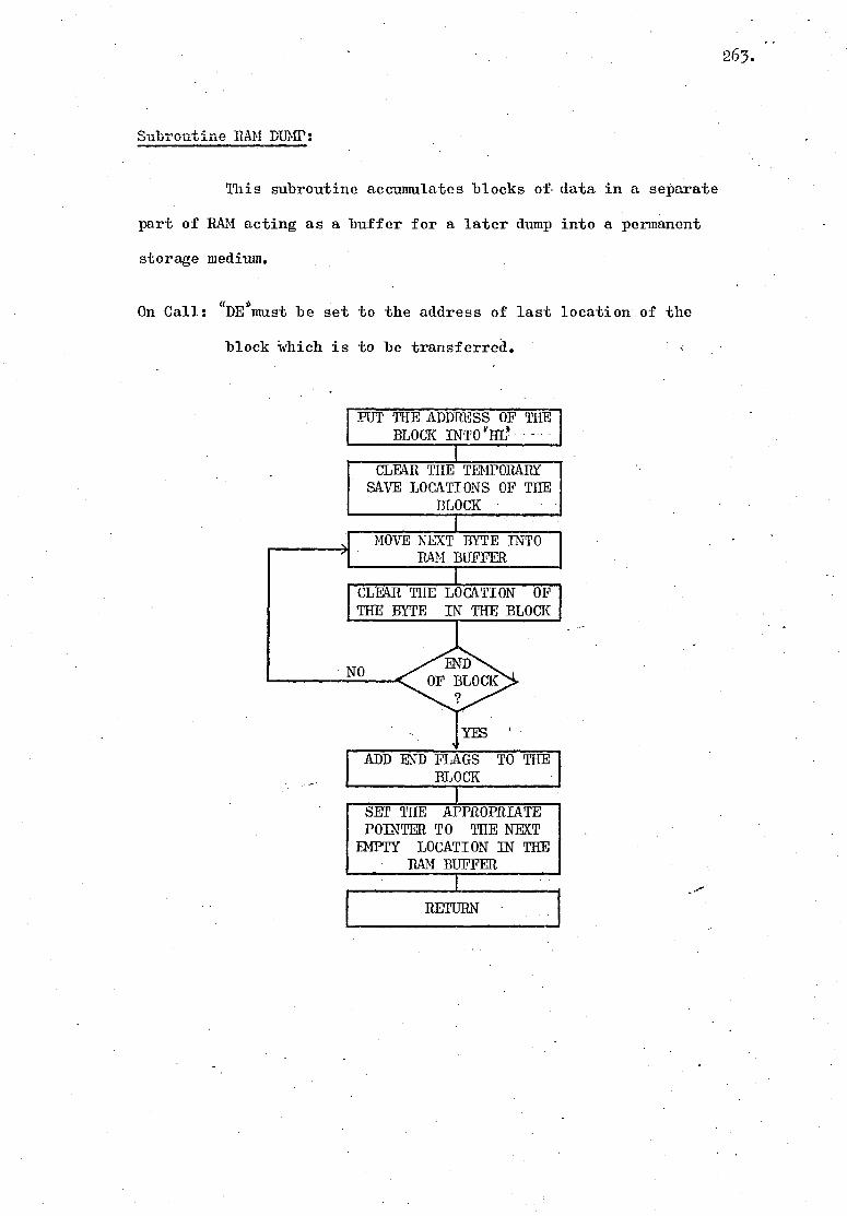
Subroutine Will DUMP:
This subroutine accumulates blocks of. data in a separate
part of RAM acting as a buffer for a later dump into a permanent
storage medium.
On Call: "Demust be set to the address of last location of the
block which is to be transferred.
PUT THE ADDRESS OF THE BLOCK INTO'HL'
CLEAR THE TEMPORARY SAVE LOCATIONS OF THE
BLOCK
MOVE NEXT BYTE INTO RAM BUFFER
r CLEAR THE LOCATION OF THE BYTE IN THE BLOCK
NO
ADD END FLAGS TO THE BLOCK
SET THE APPROPRIATE POINTER TO THE NEXT
EMPTY LOCATION IN THE RAM BUFFER .
RETURN
263.

Subroutine LOC FIND:
This subroutine finds the address of location whose content
is equal to the content of the accumulator.
On Call: u
A r~ is equal to the required value.
uspoints to the address of the table to be searched.
On Return: M-flag indicates that the end of table is reached.
4HLapoints to the required location.
Subroutine CLR TBL:
This subroutine clears the entry, which is equal to the,
content of Accumulator, in the table addressed by the content of EL..
On Call: "Al is equal to the required value.
'1J]L points to the address of the table to be searched.
Subroutine NO. DIAL:
This subroutine increments the 5-bit counter representing
the dialled digit and returns with Minus flag set,if the count shows
more than 12 (decimal) dial pulses.
Subroutine NEW DATA, Subroutine LAST DATA:
These subroutines load the new input data or the last
stored data into the accumulator.
Subroutine LD -YHL, Subroutine SDEXHL:
These sub routines load (or save) DE with (or in) the content
of M and 14+1 where the address of M is given by Imm: register pair.
264.

Subroutine SAVE LOC:
This subroutine takes the content of. the pointer of the
required block and loads the address of the next free location of
the block into the IlL register pair.
Subroutine NEXT LOC:
This subroutine sets the pointer of the required block
to the address of the next free location in the block.
Subroutine SB DE EL:
This subroutine subtracts the content of DE from the
content of HL and puts the result in DE.
265.
. APPENDIX (6)
DETAILS OF THE MAIN-FRAME COMPUTER PROGRAM FOR FURTHER PROCESSING
OF THE FINAL RESULTS
266.

267.
7..3,04,20. 15.56.5'3.
00000C 4444-ivt.4...v4 PROGPW
0006IC- TP I? PRCGRAm DECODES AND FR rvr TPE TI=LEPHCNE TRAFFIC DATA COLLECTED
066:...7.r FY rICPCFPOCESSOF IN A FECIAI. CODc:11 OCTAL FEENOT. -:H11lLD E RUM UNDER :TOF" SYSTEWT:ATCH,600O0).
0.1.a05C 00006C O1000 PROGRAM PIALI(INPUT'OUTPUT,TAPF5=INPUT■TAPE6=OWTRUT) 01010 DIMENSION /:D.::1010:.!-V51-.1) ,11DIGITi.G■SDIGIT:EOFNDIGIT(8) 01011C KESIZE IS THE SIZE OF 1.a(I) VECTOR. 0101.2. DATA 7E/100/ . 01015 DATA;TPC1).1=1,100,/?4277BIS77.6446E!.065F,157E,0661 ,237P.146Dp217B,. 01016+ E47F.'237F'SIOPle37E!OESP.010t1046P,020F.147E,W:OE,27SP!0SOF!'354D, 01017+ C.J0F'005F'365P,166P!006E,1211-!!000P■O'111.,001E425F.74■163B,377E'24277D, 0101E+ 14:1vP,665E1164E,061:'224P.'142P9214EFS6E.E,ES4P,OS:0"PIOS5.D'207E015D, 01015i 2,12EF075P,12CP,026P21.2D026E,005LF226Ey166B'Oij6P1115E,000Dy000B, 01M0+. 000E'122Bi167E'44377B/ 01021C • 010E4G 01025+ *:142,77B, 01026C 01.027 WPITE6,001) 0/02* 601 FORMAT;://20X!4TELEPHONE TRAFFIC STUDIESit/a2X54SUBSCRIPEP rEHAVIOUR)4,/ 610294.j24—DIGIT NI EERS• DIALLED.IGNGRE DIGIT "10".*/3X.*TINING ACCURACY*, 010:30+ 4T0 .'ITHIN 26NS.0)JITHIN 2.64 'SPC. FOR CALLER RECEIVING ANSWER.) v'"> 0103IC 010320 "I" GIVES THE STAPTING KT <I) LOCFiTION TO FE LoADEr WITH DATA 010?2C" KE(ISTR) IS THE FIRST LOCATION OF NEXT PLOCK .OF DATA IN }(P.(I) 01024C 01025C 01026 .1.=:1. • 01027C 01022 100 ISTR=1 61029C • 01040C PROGRO. DIAL1 USES DATA STATEMENTS AND NO EXTERNAL DATA SOURCE. .- 1.7.41C TO LOAD DATA FFOM AN EXTERNAL SOURCF,"CALL" SUIFOUTINE PT THIS .1;.,42C STAGE OF PPOGPAWSTART LOADING INTO Kt(I),WITH "I" AS SET BY PROI3PH.) "44444444440
01050 1-.11 ile 01051 1.:Be:D=KE<I).AND.277B-0105P 110 CONTINUE . 0105? WRITE 22) F F 4I) T.1,106 (105.1 22 FERr.IAT DATA IN KB(I)*//.'.10(02:,IX))/) 010Fi!1C 01056C INITIALISE ALL VARIABLES 01057C 010eS0 120. I=ISTR 0101S1 DO 2 .1=1,50 0106? KA<I)=0 01 067-: 2 CLINTINUE 01 1'64 LINAPR=0 01070 LIFTf1 010::!A MLIFT=0- 01090 SLIFT=0.0 01100 WLR=0 C1110 SCLR=0.I) 61120 MANSR=0 (MO SANSR=0.0 01140 DO 3 Iz21,8 01150 FlrI1IITI)tO 01160 MDIGIT(I)=0 01170 :5DII5IT.1)=CI,0 011*0 ? CONTINUE 01190 NTONF=0 01;:. 00 ..,. OP=0.0 • 01:1- 10 MPTrNF=0 I,20 SPI. C.ME=0.0
e -J?:.1*1 rDIF-L-6 01240 SfliALt:0.0

268.
il .gicG-.13 1 ~. •: ~ 1.1 1 2ti t:c C 1 _ 7 6t_ LCDV FO F: HEADER
01281 I O 13') I_ I _; T,P . 98
il;`90 IF..'F 'F•''i'• . E1'.?77E . Ai1I1. ;F;E <i+i? . Er :7.7E... AND. •;rt';. L -21• .. E1r!. .77 E)) -GO TO 140 iil iil)
1:1". CONTINUE
013I of 01 _=r'( * TOP IF NO HEADER FOUND 0i•='0 =TOP 01?4r.I: HEiIIEF' CAN EE t•1OF'E THAN THFEE 377Brc . :_"EHF:1_H FCR NON HEADER 01:.90C
.
':1'::60 140 .1-1 011;70 IF -F ~:B .f> . NE. 77Ei G❑ TO 150
01=:90 I I G O TO 140 - 01 4': iIC F I F: T NON HEADER FOUND 0i41i'C 01420 1Cil F;H•..~.>-KB{ii ~; 014_11 -•<'F-.E'' 1T1J. Eb!. 3 7Bi.AND.(F•.E••'I 2) Eli :7 E At+D.(FE•;1T= ._I:•.:77Dii 0 TO I6C 01440 01450 1=1'r1 lit 45IC I:I$ .i:1: END CF KvI) ? 01 470C 01480 IF 'I . GT. K : I E) GO TO 170 01490C
01'100 G❑ TO 150 1510 Iei72oc PUT HEADER FCF NEIaI DATA T ❑ IE LOADEII INTO K E . ii 015:0 170 F: E 7 7s 01540 F B •'ci = 3778 111r`"IJ FE• _ -377B 1,1560C H L F T THE F'EF1A I N I NG 111FCF FIH T I ON TO THE TCP CF FF •'. I i, '=:❑ THAT ii_ 7 C: THE NEW PATH TO 1E LOADED INTO FB{i FOF?1 "= CONTINUOUS COLON!' .
111`551::,: OF DATA READY FOR PROCESS. • 01590C 01600 t; +.3 01,'110 to 180 i-444 0i'.20 1'F. 'i: =F•'A I-'3) 0_h3€' 180 CONTINUE* 01'._ 1 1~- t'iTl 016 .,H vvvv.:vv..vvvvvvi 04 016-10': t1E;":T It1 •'_ :TF'UCTION CAN BE '.:ET O"170 TO ;eo" FOP A +CONTINU❑L1 _; PUNNING 01650C AND LEADING F'CFE DATH FF'❑N HN E ; T EFNAL SOUFCE INTO F`B iii . 011_60C DIAL1 _TGF':• HERE. 01670 STOP 01-2.71C 01672 _ 1I1680 160 lS.lP-IT1 hi 1-.'! I!I_ 0;700C _TAF.T TFANELAT ING T1=NE INPOF'F1HT I❑N 01710r 01,r2i0C 01730 IF•'.•J.LT.ci '3D TO 120 01740 LINADR:=KA.1i 01."('50C I117t:0C FIND OFF-HOOK TINE 0177n: 01780 CALL T IF1E '•:'KA. , 1,HIN,:_EC• IT IME,LIFT) .
01790 i_IFT=17iHE 01800r 01E,10C LIFT I. THE OI:TAl. VALUE OF OFF-HOOK TINE
? il FILIFT=F1tN • 01:7.40 _LIFT-SEC o1::4il_ 0 1:4 2 C

269. .
01850C
01',I60C FIND OP-HOOK TIME 01~rkC 012::0 CALL TIHEX(MP,J,1,HIN,CEC, lTIME,LlFT) 0ii~0 m~LP=~J~ .
V~9O0 JCLP=SEC 0|510C o19acc CALLED EUI:[PIDER ? 01::0t
6194o IF/(KH/4).P'"I.004r..AUD.(KH(5).E0.004E)). GO TO 190 0!550 Ir GO TO 200 Vl9E0C 01:'70C HC TOPE . CENTIME TO GET PPE-TONE D/FOFtATIQN 019:i0C ~~TP~E=~,2,3 MEAH:-:UU:U[CE::FUL,SU[[EC':FUL,U9 CALLED 311BCCRIDER 01550[ !TONE GIVE.: THE PO:ITION COUNT OF L6.:T PO:EILLE PRE-TOHE INFORMATION 02000C 02P10[ Ur:U[CEE:RJL CALL 0ao:0C 02030 2C2 l~7HTE=~ U040 JTCHE=J-2 020':0 GO TO 210 020e0r CALLED :UE:CRIBER e2070C ~20~0 I90 IS.THTE=3 me90C HP:1, ER 7 ' cal0oC 0ill0 lF//Mo/E).E0.00~D).FND.(J.E0,10)) 6O TO 191 02120C PRD^T [k.T IF NO HNVWFR ` 02t30 ~r? TO 500
02140 151 [ALL TIHEX(FH,8,1,MlH,CEC`ITIVE,LIFT) V2176 VAN:PL:MDN 02160 02170 6O TO 500 021m:. 02190C LD^E wA? HET CALLED. 02200C LLOi. FOP TONE 02210C 02220 200 IF'.KH(J-4),E0.000D).F{D.(KH'J-9),E0.005D)> 6O TO 201 02230 1.LE,12) GO TO 202 2"3 02240 IF((xH/~-4).EQ.VV6D).AND.(KA.(J-7,.E0.600r,.AnD.(KPc]-12).EQ.005D))5O TO2N 02250 GO TO 202 02260C
02270C TONE RECEIVED,8N[D CALL NAS iXNSUCCECCFUL 02280C 03250 201 ./TONG-..1-9 02808 I*:THTE=1 02310 CALL TlHEX(K8,J-7,1,MlH,EEC,ITlME,LIFT> 0232~ HTOPE=1111
CTONE=SEC r,2240 CALL TOHE/KH,J-6,KIUD) 02130 GO TO 210 ^ 02:*60C 02:70C '7UCCE~':FUL CALL 62320C--' 02390 20: JT[NE= J-12 o240o I~7HTE=2 02410 (ALL TIH[X(KH,J-10,1,HIU,*:EC`ITlHE,LlFT) 02420 MTUNE=MIU
:TCHE=~BC 02440 CALL TOHE(KH,J-9,PlHD) 02441 CALL TIMEX(MH,J-2,1,11IH,ZEC,ITIME,LlFT)' 02442 rPY:R=HD\ 02442 EHN:R=CEC 024r:;0 6O TO 210 0245iC
^ ' ~
~.:452C 02453C

270.
,'.2470C PRE T CNE IHFCF't•1ATION :124•71C il248CC DTENE-I'IFL_Tor1E 1)249o1_ I'I1= I T-DIALLED DIGIT 02r;00C IIDIAL.: IIINL 1=I'/E TINE OF START DIALLING ':25111C • I1I'i1_ITr:S.li1=IT GIVE TINE OF DIALLED DIGIT 02520C COTE:riDiGIT IS INITIALISED TO "10" TO ALLOW IINLI_ED DIGIT IDENTIFICATION.
:25:3':' 2101 IF,.. :A:7: .GT.207F,.AII1. • A<.f•).L1.221.1E:, ) GO TO 220 02540 E1:-Iil
1i,F{~:1'A;:'?).GT.2 TE:%.A11I1.;1~:Hk:• 1).LT.24i~E:,.; GO TO 240
0255ii GO TO 250 025E0 02570C DIAL TONE RECEIVED TIME 0257 1C 02 iiC •' i1`59i1 ;=2') CALL T INEX•'KA1 7 • o,riIN,'1:EC, i T ir•1E,LI.FT) 02600 r'1U T Cr.E-FJIH ('ERi ii :.DTONE-='EEC 026E0 I_(1 TO 230
_TAF:T PIALLIN'. TIME 02640C 026501 240 CALL TI1•1EXWA 9 .• 00.1Iri 3EC5 I T it•1E,LIFT) 02460 r/IIIHL-r•1IN •
i' r.7i1 :DIAL-5El,
021:90C DIGIT: DIALLED AND THE DIALLING TINE OF EACH 02700C "L" COUNTS THE N0. OF B't'TE: E:EFOF'E ANY TONE iNFOF't-'ATiON WAS REGISTERED 1l_71 0C 112720 250 L-11 02721 LL=10 02730 ;?r.II iF•'C1.'A +L::•.GT.007F:>.Ar1D. KAM:L?.LT.cilitr::>.ANf_1.<L.LT..J7rr1Enl;0 TO 270 027-1E IP CONDITION FEF A DIALLED DIGIT DOES HOT E <:1 T' F'F' i r+T OUT 02750 1=0 TO 5 00 02760c 02770C DIALLED DIGIT AND ITS TINE OF START 02780C 02781 270 CONTINUE 0c79i, CALL T ir.E:F.;tA.L' I' NIN, :E(, ITir-IE,LIFT, 1)2 ,, i1 PD i 1_ I T : L-LL: -r•I IN C :1i1 r11_Iī <I_-LLI-'SEC i12::::0 r=DI1_ I T 'L-LLI = . NIFT•:i:.A.;Li -3% . FIND. i1:37B na:?c:i iF:.NI1i13IT•:L-LL%:E1_'.1ii; HDiGIT L-LL)
I_L-LLTi 02E30 L-L+2 02%340 GO TO 260 i12::5i11 0 51C 102 5•_C
02:370C
r. • 5. 5 ; : c- i.12'~:•?i1 .~i.1:j (.G TO , ,11j•._=i1,.,_.o; • 1:?.THTE 02920C
02950C UN 3Lil=.f;F S:;:FI 1L CALL PRINT OUT
02971: 5111 b;PITF6-!..710i I_ INyt1F. :ND f1-i T ..'ii. I-1'4) 02920 710 rnnNAT '!i!~-LNE AIrr .;u TP.i: -- DIPL rI
j 1 =••F-PE•1•i7 .•.--I_hLL NOT 1-N:lt'L_F.EI1 ~./`. 02'990 170 TO
_ _ 50
03000C
! r
PRINT CUT INSTRUCTION

271. .
.1', 31J0k: 07:010C SUCCEFUtCALL Keaoc 0200 720 wRITE ;.6.720). 6?040• 7E0 FORMAT.7:///2x....LINE ADDR .;;OCTAD: DIALLED -- II 6;:12,1X).t-- I I-LL LEFEtI 02050 GO TO 550 0?n6On 0070C CALLED LINE 03KOC 02090 720 wRITE.'6.720 LINADR 02100 720 FCROP“ ,'//2X14LIVE ADDR.0JCIAL) ---7.0'7: -- UR'S CALLED 4,) ('.l 10 wRITE.6!731). 02120 721 FPFIIPT<9XlvDETAILS:■.//22X'4EVENTv,15X. ,..TIMUNIN.13X -' 0?121+ vIIHE<SEC.:',4//) 02120C 0?140C CALLED LINE DETAILS 02150C 02160 WRITE;:.6!722) HLIFT.?LIFTWANSR , ?ArISR■PCLR'SCLP 0s170 7?2 02171+. I2.20.F5.i'v2eX.»END OF CALL....T449IS-, 20X1F5.2/) 021:30C FROC;RM.. CAN NOW CONTINUE FUR NEXT SET OF DATA 0?190C 02191 GO TO 120 02E00C
10C PUPILS OF CALLER f:EHAVIOUP 02220C 0'7..230 550 "PTE 731;. 0?246 VLIFT■StIFTWCLR.SCLR 0?250 551 FORHAT0X.A.OFF-HOOKv.744.13,20X,F5.2/ 0?260+ 20:,v0P-HD0r4.T44.*L3.20X'F5.2) . 03E70 WRITE6:7..552':ODTONF.FDTONE.ODIAL.SDIAL C?2.0• 552 FOFm.T.-E0x.vrIAL TONF4.T44,I0X,F5.2/.
19X'v?TRET DiALLING4■T44,I?■20X'F5.2) 02?0 PO 55? 0.3310 wRITE1554:. 02?20 7.74 FCR1AT;- 16X5I1q2X!vDIGIT DIALLED....I44.13120X.F5.2) 02SM 552 CONTINUE 02240 GO TO (610.620.6?0,640)WIND 0??50C. 0260C OTHERWISE FRINT OUT ANSWER - 02?70 Gn In 670 03?:DOC o?s9ec TONE IS UNIMOW 02400 0?410 02420 024?0C
610 hIRITE;.'61611'.. MIONEpSIONE • 611 FOROAT16X,v7*'4X,4,TONE4q1-44,I220X'F5.2) GO TO 670
...-• 02440C NOIDER UNEETAINAELFM0) TOW 0?450 6E0 YRIIE:61621) NIONE,STOPE 02460 621 FOR11ATi.20Xo.HU.v,3X'vTO14E491•44 !1320X,F5.2) n3470 GO TO A70 0?480C 02490C BUSY TnHF 025,00 630 WITE (6.6.1) HTPPESTONE 02510 631 FORNAT.'20X'vESY4,2X,i.TONEv.T449I3420.4,F5.2) 03520 GO TO 670 07:20C 0?540C RINGING TONE 02750 140 PTOPE.STONE' • 02560 14:4; FEPPA7.20.4,RING.,'1Xii,TONEi,.-144.12.20X'F5.2) 02570 CO TO ,.FI:' o.35P0 670 mFITE 1.1--SP,spp.SA OS:590 671 FORNATi.20Xo-ANSI.:FRii, 7744.7?'20XlF5.2) • 036001-:. 0?1-210C FROGPN. CAN EE ET To PPZUHE NEXT PROCESS D'T "GO TO 120 " AT THIS POINT 0?611 GO Ti) ;ao II (57:620
02640 END' n264IC
••••••31.•••■••••••- • - . , „ ••• • •••-••• "• -,•—• •
• s • . • . •• • • F....4v

272..
SITF;CUTIOF T I H. F
01700C SUFFPUTIOF CPLCIA.PIFS THF TIHF GIVEN IN T''0 EYTES PHD
(.77101: GIVES THE RESULT IN HIOUTFS POP :EC:CODS i HEPOS BITS OF INFO.Frr--TICH ON TINE .
r - A . . " IS PWIILAELE ONLY
0::;7a0C THE IITHEF S PITS I TP F EXTf1707TED FELT " LIFT" *TrifFOUTINE 7INEY0:471'.._;J'N5NIN,SEC.ITIMELIFT).
01761 0IVEOSIOH.KP(50) 027i12 ITIHENKR<JJ::.• • . 0.171-1.!?
0'1770 TTI!-IE-HIFT.'*ITII.IEH.:7).P.HD.177400B 037!1!0. ITTrEL,ITINE.ORITIVEL.PND.277T) ' cr3790 NH14r14-1 1.1'10 GO TO .fsecsopio), HH 11:21101-' 0?!7.43riC
0:1:7-!62 ?t0 Iv:, TT
TTrL7 i: GIV, IN It BITS FOPIIAT r. • •••7:.(.1-. 01.90 :100 'T7I;.!..F.,-rITINE.PHD.7.3777P'
01900 IF.g.TIME.LE..fLIFT.PHD.:777B):. -GO TO *01 - 9 1 0 C
0392(iC THE Il BITS SHCV FN EVENT PFTEP OFF-HOOK Cr:92.0C 0:1940 ITIME..ITIME.OP..fLIFT.AND.174000B)
01.97.0 GO TO 8071 07:960IS 0970C THE I BITS SHOY FH EVENT EEFOFE OFF-HOOK. FIT ONE TO UPPER !:; PITS.
ITT!"F=<ITIME.GF,LIFT.F.H11.174000E)>+004000P 04 0 0 0 C 04010C 1.-..HPOGF TITE TO- PILLI'SECONDS 040a *.:02
14,1 0 P::F.C.:=FLOPT“TIVE.,.- 1000.0 04040 04 0 t."1 0 0407.IC GET EF' v CFIGIPPL OCTPL VPLUF CF IT 11E 0.4 0,7.2 04 0 0 C
0 4 0 7 0 FETUFN
0 4 0 0 EHD •
040s2C 04 irErr:C 040901:
04091C -1.:UEPOI:.77NE 7 0 N E •
04100C THIS SUF.1;OliTINE FIHTS THE TYPE OF TONE PFCEIVFD
04110C KIHD=1..1..:".4 FINGING TONE FESPECTIVELY
.04120C N:..7.EC 13 THE CCUP7FF FCP THE NI 'I OF ii i 1]NT
41.?01: NaT THE 1 f4EEP OF TONE-DO :::PNPLES FElECTED DURING 0.5i4iSEC TIME ▪ 4140C e415G .7WEFCU77NE TCHE.TR.JK,KIND> 04151 PIMF11.7 I0r: rp.:5o O4IS
N:r.1 1FL:KAJK-i-1) 0416 01: 04170
041.i0 .7.r TO
041'90 IF.'..:1 4 FC.E17..005B,E.P..;HSFC.F1 1.00-1 GO TO 9t0 FETUPH
04,?tec
12.;aar., 9t 1) tit -4 •
IF.'..:N:rF.GT.P.,0P%.POD.:HTPF.LT.100F)> rit,p=?
0,4S1.1
Cks,12III • 11i11 f ¶ ripI I 114;r1. ,..c:r.".••I 71•ft,,A
70 IF .f..1 4•:-.NP. 67. i ; OF • . PI if VP LT. IF,:OSHF.GT.200B:,
Ii II ,7.Er14:-H r;,T.

273. APPENDIX 7
DIGIDEK MODEL P-70 is a parallel input/output incremental
cassette recorder capable of incremental or continuous operation.
The continuous mode of operation can be used as "Incremental
Structure" or "Block Structure", the difference being in the speed
of writing and the packing density of the tape used.
A 300 ft. cassette tape can store between 50,000 and 120,000
bytes, according to the selected mode of operation, with an error
rate of less than one per million. Data rates of up to 40 bytes per
second in the Incremental mode and up to 700 bytes in the continuous
mode are specified with a tape access of over 400 bytes per second
and over 800 bytes per second, respectively.
The tape speed is controlled by an adjustable voltage—
controlled oscillator of 930 Hz/volt. The voltage—controlled clock
pulses form the Motor Clock Frequency which is needed to write -a
byte and create markers on the tape. Nine clock pulses are used to
write a nine—bit word on the tape and the two remaining clock pulses
produce two markers per word (hence, eleven bits per word). .
The recommended write time t for each speed of the tape
is given by:
tit S = 1 x 11
where f is the Motor Clock Frequency. The follōwing table gives
the recommended tape speed and the write time delay (byte strobe
delay) as well as the write delay which is the time needed to
speed up the tape before the first byte strobe (BS).

274.
Speed of Tape (inch/sec.)
Write Delay (ins.)
M.C. Frequency (kIIz)
BS Delay (ms)
2 10 1.1 10
6 20 3.3 3.3 9 30 4.95 2.2 14 60 7.7 1.42
The Incremental mode operates on the 2 inch/sec. and needs
a Write Delay to precede each byte as well as a BS delay to write
that byte. In addition to those above, a stop delay of maximum
12 ms is also needed before the next increment. Therefore, each
byte takes a maximum of 32 ms and a minimum of 20 ms to be written.
The Continuous mode, on the other hand, needs only one
Write Delay before the first byte and only the minimum of BS
delay for each write (Block Structure).
A 40 ms start time has also to be added before any change
in the Read/Write mode of operation on the tape. This is to allow
for field currents to collapse and avoid erroneous read or write of
the first byte.
A new character is written each time an active low Byte
Strobe (BS) is issued followed by the READY (RDY) signal, within a
period of 400 ns. The data is to remain stable on the data input
lines from 100 ns before a BS and until the RDY signal goes high.
A new BS can be issued any lime after RDY goes low again, indicating
the readiness to receive a new byte of data.
The cassette has•to be primed before it is used for Read/
Write operations.. The priming includes running the cassette off its
clear leader having inserted it correctly into the recorder.

275. .
REFERENCES
1. McGlyn, D.R., Microprocessors, (John Wiley & Sons).
2. Klingman, E.E., Microprocessor Software Design.
3. ' 8080 Microcomputer Systems. Userls Manual, (Intel Corporation)
September 1975.
4. Barron, D.W., Assemblers and Loaders.
Smol, G., Hamer, P.R. and Hills, M.T., Telecommunications:
A System Approach.
6. Tally, D., Basic Telephone Switching Systems, (Hayden Book
Company, Inc.) -
7. Smith, S.F., Telephony and Telegraphy A, (Oxford University
Press).
8. Atkinson, J., Telephony Vol. I. (Pitmans), 1957.
9. Atkinson, J., Telephony Vol. II. (Pitmans), 1957..
10. •Chapple, K., Expansion by Contraction. Microprocessors, Vol. 1,
No. 1, 1976.
11. Verhofstadt, P.W.J., Evaluation of Technology Options for LSI
Processing Elements. Proc. IEEE, Vol. 64, No. 6,
June 1976.
12. Raphael, H., Evaluating a microcomputer's input/output
performance. Electronics, Vol. 49, No. 17,
August 1976.
13. Row, M.D. , The Selection of Microprocessors. Post Office
Electrical Engineering Journal (P.O.E.E.J.), Vol. 71,
July 1978.

276.
14. Lofthus, and Ogden, D., - 16—Bit Processors perform like •
minicomputers, Electronics, Vol. 49, No. 11, May 1976.
15. Post Office Telecommunications Educational Pamphlet (POTEP),
Operation of the TXK1 Local Exchange Crossbar System,
Telephones 3/13.
16. POTEP, Telephone Traffic. Telephones 6/3.
17. POTEP, An Outline of the Public Telephone System. Telephones 6/1.
18. Syski,.R., Introduction to Congestion Theory in Telephone Systems,
(Oliver and Boyd).
19. Electronic Switching Systems: 1 — TXE2 Electronic Exchanges.
(GPO Telecommunications 1969)..
20. Benton, R.H., Cowan, R.A., Maynard, K.J. and Scarfe, R.T.,
Programming and Microprogramming of Microprocessors.
POEEJ, Vol. '70, p. 234. January 1978.
21. Bliss, C, Build or Buy? Microprocessors, Vol. 1, No. 1,
September 1976.
22. Bastow; F.J., Collingwood, J.W., Newell, R. and Price, C.K., The
Pay—on—Answer Coin Box System, POEEJ, Vol. 51, p. 343.
23. Goodman, J.V. and Phillips, J.L., TXE4 Electronic Exchange
Systems, POEEJ, Vol. 68, p. 196, January 1976.
24. Description of the Line Finder 41lotter Control and Start. Circuit
used in Conjunction with S.B.2100—type Relay Line
Circuits. AEI Telecommunications Division, Report
No. 5848.
25. Description of the First Selector. and Control Circuit Automatic
Equipment No. 17. AEI Telecommunications Division,
Report No. 5434.

277.
26. Description of the Group Selector and Control Circuit. Automatic
Equipment No. 17. AEI Telecommunications Division,
Report No. 5440.
27. Description of the Final Selector with Transmission Bridge.
Automatic Equipment No. 17. AEI Telecommunications
Ltd., Report No. 5881.
28. POTEP, General Purpose Telephone Relays — General 3/4.
29.. Povey, J.A., and Cole, A.C., The Use of Electronic Digital
Computers for Telephone Traffic Engineering.
POEEJ, Vol. 58, p. 203.
30. Vigar, C.D., Trunk Traffic Analysis Equipment. POEEJ, Vol. 58,
p. 253.
31. Golesworthy, H.M., Kyme, R.C. and Rowe, A.T., The Measurement
of Telephone Traffic. POEEJ, Vol. 64, p. 227.
32. Vigar, C.D. and Brookfield, J.T., A Computer-controlled Traffic
Recorder. POEEJ, Vol. 64, p. 234.
33. Holmes, H.S., Telephone Traffic Recording and Forecasting.
POEEJ, Vol.., 67, p. 201.
34. Bear, D., Telephone Traffic Techniques. Proc. IEE, Vol. 122,
No. 10R, October 1975.
35. Kyme, R.C., A System for Telephone Traffic Measurement and
Routing Analysis by Computer. Proc. of 7th Int. Teletraffic Cong., Stockholm 1973, p. 525/1.
36. Cox, D.R. and Smith, W.L., 'Queues (Chapman and Hall).
37. Bear, D., Principles of Telecommunication Traffic Engineering.
IEE Telecommunication Series 2.

278.
38. Sapsford, B.G., Measurement and Analysis Centre: Part I — System
Concept sind Equipment Description. POEEJ; Vol. 70,
p. 243, January 1978.
39. Interscan Communication System Ltd., Catalogue of Interscan
Traffic Data Analyser.
40. Telephone Rentals Ltd., Call Information Logging Equipment.
Technical Report 1, Issue 11, Vol. 1, Winter 1977.
41. Plessey Communication Ltd., Call Information Logger (General
Information).
42. Podmore, B.F., SCEPTRE: A Portable Electronic Traffic Recorder.
POEEJ, Vol. 70, p. 270, January 1978.
43. Scott, W.L., Electrical Contacts in Telephone Exchanges (Part 1).
POEEJ, Vol. 61, p. 263.
44. See Ref. 16.
45. Burville, P.J. and Barber, S.E., Traffic Recording: Call Detail
Analysis. IEE Colloquium on Application of Micro-
processors to Telecommunications, February 1978,
Digest No. 1978/17.
46. POTEP, Loop—Disconnect Pulsing, Telephones 5,/2.
47. Pain, H.J., The Physics of Vibration and Waves (John Wiley).
48. Rastra Electronics Ltd., XR-567 Monolithic Tone Decoder,.1972.
49. Arthurs, A.M., Probability Theory, Dover Publications Inc.).
50. Sapsford, B.G., Measurement and Analysis Centre: Part 2 —
Processor Programming and Operation. POEEJ, Vol. 71,•
April 1978.

279.
51. Brown, R.S., A New Method of Tone Identification. POEEJ, Vol. 71,
P. , y 117 July 1978 r ly ~r .
52. Post Office Requirements for Telecommunications Exchange Systems
and Subscribers Apparatus. Supervisory Tones,
Ringing Supply, and Recorded Announcements.
POR 1080, January 1971 .
53. Bo, K., Gaustad, 0. and Kosberg, J.E., Some Traffic Character-
istics of Subscriber Categories and the Influence
from Tariff Changes. Proc. 8th Int.Telctraffic
Cong., Melbourne 1976, p. 324-1.
54. Leigh, R.B. and Little, A.J., Busy Hour Traffic Variations
determined from Continuous Traffic Measurements.
Proc. 8th Int. Teletraffic Cong., p. 262-1.
55. GEC Telecommunications No. 39, 1972. Stored Program Control.