Embed Size (px)
Citation preview

A-e?21 AIR FORCE INST OF TECH WRIGHT-PATTERSON AF8 OH SCHOOL-ETC F/6 15/5SOME CIVIL-ENGINEERING AND MANAGEMENT ASPECTS OF CONVERSION FRO--ETCCU)JUN 80 S M PITTMAN, J P SMITH
UNCLASSIFIED AFITLSSR5-8 N

00 ~
00
WOW wii

W>2
SOME CIVIL ENGINEERING AND MANAGEMENTASPECTS OF CONVERSION FROM JP-4 TOJP-8 FUEL BY THE UNITED STATES AIR
FORCE IN THE CONTINENTAL UNITED STATES
Steven M. Pittman, 2d Lt, USAFJ. Parke K. Smith, 2d Lt, USAF
LSSR 5-80
for pubLC] t _, o,;-.:,,. it...ted

The contents of the document are technically accurate, andno sensitive items, detrimental ideas, or deleteriousinformation are contained therein. Furthermore, the viewsexpressed in the document are those of the author () and donot necessarily reflect the views of the School of Systemsand Logistics, the Air University, the Air Training Command,the United States Air Force, or the Department of Defense.

USAF SCL 75-ZOB AIT Control .mber LSSR 5-80
AFIT RESEARCH ASSFES
The purpose of this questionnaire is to determine the potential for currentand future applications of AFIT thesis research. Please return completedquestionnaires to: .4IT/ LSH ,Thesis Feedback), Wright-Patterson AFB,Ohio 45433.
1. Did this resea-ch contribute to a current Air Force project?
a. Yes b. No
2. Do you believe this research topic is significant enough that it wouldhave been researched (or contracted) by your organization or another agencyif AFIT had not researched it?
a. Yes b. No
3. The benefits of APIT research can often be expressed by the equivalentvalue that your agency received by virtue of ART perfoming the research.Can you estimate what this research would have cost if it had beenacculished under contract or if it had been done in-house in terms of man-power and/or dollars?
a. Mn-years $ (Contract).b. MNn-years $ (In-house).
4. Often it is not possible to attach equivalent dollar values to research,although the results of the research may, in fact, be important. Whether ornot you were able to establish an equivalent value for this research (3 above),what is your estimate of its significance?
a. Highly b. Significant c. Slightly d. Of NoSignificant Significant Significance
S. Cents:-A66
NTIS iA&ii DDC TAB' Un .nx-nced~J,_t ific tion_
By
A.=It I t
Dist )c 4 al
N ' and Grade Posizzon
Organizat±m on

111111 POAGIEIN T wo
PINAft FOE PROVATS UUI. $300 UNI - . -
I BUSINESS REPLY MAIL I _____UIS GI PUGR? N& n= WaN~i H L MEON
@UA= WILL N PAID IV AMOSU ________
AnTI/LSH (Theuis feedback)MEONEV:±g.~-a~esouAn OIL 45433 _______

SECURITY CLASSIFICATION OF THIS PAGE (Whe~n Dato £nfered).
REPOT DOUAANTA.ION AGEREAD INSTRUCTIONS
REPOR REOR DCUETAIO PG BEFORE COMPLETINCI FORM~~~3~fl5J.MISI~- /2. GOVT ACCESSION NO. 3. RECIPIENT'S CATALOG NUMBER
tcrT'-LsSR-5-8 9.1_____13__- S. TYPE OF REPORT 4 PERIOD COVER
ON ,VIL ffGINEERING AND A AGEMENTEC Ot,46NVERSION FROM" 4 TO Q-8 9 Mastiers hess
THE-ITEDNATE 'JOCE IN MNetVG
7 8. CONTRACT OR GRANT NUMBER(sJ
J. Parke K. Smt 2nd Lt, USAFPERFORMING ORG=1I ZWAME ANO AOORESS3 10. PROGRAM ELEMENT. PROJECT. TASK
Graduate Education Division AE OKUI UBR
School of Systems and Logistics,/Air Force Institute of Technology WPAFE 0s
1I. CONTROLLING OFFICE NAME AND ADDRESS i A
Department o± Communications and Humanitik ZAFIT/LSH 1.N
WPF H4r.433 R14 OIOIN AG DRESS(If dli~aomt from Controling Office) IS. SECURITY CLASS. (atis ~e port)
UnclassifiedIlsa. DECL ASSIFICATION/ DOWNGRADING
67 1 SCHEDULE
1S. DISTRIBUTION STATEMENT (of ths Report)
Approved for public release; distribution uniimited
17. DISTRIBUTION STATEMENT (of Cho abstracteantered in Block 20, it diferent from, Report)
D~j~FO PU LIC RE EASE AFR 1M17,
FUIC C. LY14MIL w. USAF
19. Key WORDS (Coudbige an revers side i naaaainsy a"~ Id"Idf by Niook nhber)
JP-4 storage and transportation facil-JP-8 ities modificationsnapthafuels conversion
Kturbine fuels20. -A"TR ACT (Continuoan toer"a side it necessary and identify by block nimbor)
JThe purpose of this thesis is to examine the possibleconversion in the CONUS from JP-4 turbine tuel to JP-i8.While many studies have been conducted to analyze theeffects of the conversion on aircraft and support sys-tems there has been little work done to analyze theeffects on the facilities in which the fuel is storedand transported. This thesis examines the erfects^# ~1~*f, VI h 111 -~ t Ii ~~A +-Anks Ang nn N I
ORM~~S17 EDITION oF I Nov 40 is OBSOLETE
SECURITY CLASSIFICATION OF THIS PAGE (When Date linteai

SSCUINTY CLASIFICATION OF THIS PAGE(WhM Date Da rearm
the piping and pumping system used to transport the fuel.Where appropriate, recommendations have been made concerningthe modifications necessary to these tacilities to counterany detrimental effects associated with the conversion.
$ICUNITY CLASSIICATION OP F U.* PAGEI Uh. Dote Efneept.

LSSR 5-80
SOME CIVIL ENGINEERING AND MANAGEMENT ASPECTS OF
CONVERSION FROM JP-4 TO JP-8 FUEL BY THE
UNITED STATES AIR FORCE IN THE
CONTINENTAL UNITED STATES
A Thesis
Presented to the Faculty of the School of Systems and Logistics
of the Air Force Institute of Technology
Air University
In Partial Fulfillment of the Requirements for the
Degree of Master of Science in Facilities Management
By
Steven M. Pittman, BS J. Parke K. Smith, BSSecond Lieutenant, USAF Second Lieutenant, USAF
June 1980
Approved for public release;distribution unlimited
This thesis, written by
Second Lieutenant Steven M. Pittman
and
Second Lieutenant J. Parke K. Smith
has been accepted by the undersigned on behalf of the fac-ulty of the School of Systems and Logistics in partial ful-fillment of the requirements for the degree of
MASTER OF SCIENCE IN FACILITIES MANAGEMENT
DATE: 9 June 1980
COMMITTEE CHAIRMAN
READER
ii
o

TABLE OF CONTENTS
Page
LIST OF TABLES ....................... v
LIST OF DIAGRAMS......................vi
Chapter
1. INTRODUCTION .................... 1
Statement of the Problem. ............ 1
Background. .................. 2
Scope of the Problem. .............. 5
Fuel Qualities. ................ 7
Literature Review...............10
Research Objectives..............15
Research Questions ............... 16
2. METHODOLOGY...................17
Data Collection Plan .............. 17
Storage...................17
Transportation ................ 18
Design to Answer the ResearchQuestion ................... 19
Storage...................20
Transportation ................ 21
Assumptions..................22
Limitations..................24
3. ANALYSIS. ...... .............. 26
Storage ..... ............... 26

Chapter Page
Hydrostatic effect ..... ............. .28
Foundation analysis .... ............ .37
Transportation ..... ............... .48
Pipe system analysis ..... ............ .49
Pump system analysis ..... ............ .60
4. CONCLUSIONS AND RECOMMENDATIONS .. ........ .68
Storage ....... ................... .68
Hydrostatic effect ..... ............. .68
Foundation analysis .... ............ .69
Transportation ....... ................ .71
Pipe system analysis ..... ............ .71
Pump system analysis ..... ............ .72
Further Recommendations .... ........... .74
APPENDIX
A. OPERATIONAL DEFINITIONS .... ............ .75
SELECTED BIBLIOGRAPHY ...... ................. 79
A. REFERENCES CITED ...... ................ 80
B. RELATED SOURCES ...... ............... .. 82
iv
LIST OF TABLES
Table Page
1. -Fuel Properties ................... 9
2. Specific Weights (600F) (lbs/cu ft). .......... 30
3. Tank Shell Thicknesses ................ 32
4. Fuel Pressure (60*F) ............... 33
5. Comparison of Thicknesses...............35
6. Total Fuel Pressure (600F) .............. 44
7. Total Pressure (60*F)................45
8. Critical Depth (60*F)................46
9. Specific Weights (-200 F) ............. 46
10. Total Fuel Pressure (-200 F)...........47
11. Critical Depth (-200F) .............. 47
V

LIST OF DIAGRAMS
Diagram Page
1. Fuel Bulk Storage Tank .............. 29
2. Example of Soil Layers .............. 38
3. Pressure and Depth Relationship. ........ 41
4. Moody Diagram .................. 52
5. A Typical Piping System .. .... ..... .. 63
vi

Chapter 1
INTRODUCTION
Statement of the Problem
There are virtually no Air Force systems within the
cuntinental United States (CONUS) which presently use JP-8
or other kerosene-based fuels. For the purpose of this
thesis project, these Air Force systems are defined as
storage and transportation facilities. Due to the possibly
significant differences between JP-4 and JP-8 fuel, consid-
eration must be given to the possible direct effects of con-
verting these systems to accommodate JP-8. Using JP-8 may
bring about a change in the design requirements and adequacy
of existing physical facilities. Therefore, this thesis
effort will examine key points involving the adequacy of
design of the existing facilities from the conversion point
of view.
A tremendous amount of research has been done as
regards the impact of JP-8 on aircraft and aircraft systems;
however, little attention has been given to the effects of
JP-8 on the existing physical facilities and equipment listed
above. Thus, a need exists to fill this void.
1

Background
With each succeeding year, the Air Force has found
itself faced with the problem of greater competition for the
naptha base of JP-4 aircraft turbine fuel. The competition
for naptha comes from civilian industry. Naptha is an impor-
tant ingredient used in the production of synthetic natural
gas and low-lead gasoline. Naptha is also under increased
demand for its use in petrochemical feedstocks (7:14). As
demand for naptha steadily increases from other fields, the
availability of JP-4 will decrease since only a certain per-
centage of crude oil can be refined into naptha and then
processed into JP-4.
Realizing the potential problem of JP-4 availability
which could arise due to increased competition for its
naptha base, the Aeronautical Systems Division of the Air
Force determined that an alternate fuel designated JP-8,
North Atlantic Treaty Organization (NATO) designation F-34,
deserved further consideration (3:2).
Procurement of sufficient quantities of fuel due to
fuel shortages and changes in the fuel supply structure may
become difficult in the future. In 1974, the United States
Air Force Scientific Advisory Board recommended an alterna-
tive for dealing with this problem. Their recommendation
was for the Air Force to convert from JP-4 to JP-8. This
conversion would tend to reduce competition coming from
petrochemical feedstocks and low-lead gasoline. However,
2

there is no valid information available indicating that the
conversion to JP-8 will help reduce the long term fuel
shortage problem. Due to the complexity of fuel pricing and
availability in general, it may be premature to assume that
conversion to JP-8 will help in the fuel supply and price
situation. On the other hand, the Board decided that, in
the long run, a switch to JP-8 will produce a net beneficial
effect (11:2).
Because JP-8 is a kerosene-based turbine fuel, there
is an insignificant requirement for naptha in its produc-
tion (16:1). Chemcially, JP-8 closely resembles the kerosene-
based commercial jet fuels Jet A and Jet A-I (11:2). In
fact, JP-8 would be exactly like Jet A-1 if it did not con-
tain the icing and corrosion inhibitors which are required
by Air Force standards (23). A majority of the aircraft
operated by the United States Air Force are authorized to
be flown on Jet A and Jet A-1, commercial turbine fuels
whose burning characteristics are similar to JP-8. Operating
characteristics and procedures are therefore available or
can be set forth from previously obtained data for many of
these aircraft (11:2). Incidentally, it should be mentioned
here that Jet A is the predominate fuel used by commercial
airlines in the United States. Jet A-1 is the predominate
fuel manufactured and utilized throughout Europe and other
areas such as Indonesia (23).
3

The switch to JP-8 would place the Air Force in
direct competition with the commercial air carriers. This
competition and the fact that less crude can be converted
into JP-8 than JP-4, does present a formidable argument
against total or partial conversion to JP-8. However, the
fact that total potential for production of JP-8 in this
country has not been reached must be considered. At the
present time, kerosene-based fuel production in this country
is centered around the Gulf Coast and far western regions.
Should conversion to JP-8 become reality, there is no doubt
that production could substantially increase as larger
refineries throughout the country begin to produce JP-8.
The smaller refineries which now produce the majority of
JP-4 for the Armed Forces would suffer initial financial
setbacks during a conversion of their facilities from JP-4
production to JP-8 production (23). It is felt, however,
that the financial burden can be cushioned by the issuance
of subsidies by the Government for conversion construction.
In general, it is believed that the availability
and cost advantages of JP-4 are fast disappearing and being
replaced by the advantages of using JP-8. Also, use of JP-8
by the Air Force would bring it in line with other NATO
countries already using this type fuel. Thus, conversion to
JP-8 would represent a "major step toward the realization of
worldwide fuel standardization with its attendant logistic
capability and overall costs savings advantages [8:3-4]."
4

Scope of the Problem
A CONUS conversion by the Air Force to JP-8 will
directly or indirectly affect a great number of facilities
and equipment within the Air Force. Everything from the
largest aircraft using the new fuel, down to the smallest
pipe transporting it will be touched by the conversion in
some way. This is not to say that JP-8 will have a great
negative effect on all fuel related systems, but neither
does it suggest that the effect will be totally beneficial.
A great deal of study is required concerning each facility,
system, and piece of equipment before JP-8 can be introduced
into the present JP-4 environment. Therefore, consideration
of the items which will be affected should include both
'beneficial and harmful effects of using the new fuel.
Study of the possible conversion would center around
a variety of subject areas. For example, the future avail-
ability of JP-8 is of great concern. Also, the cost of con-
version, whether material or in man-hours, is an area which
needs further research. The list could continue into many
other regions.
In an attempt to narrow the research effort, this
thesis team will look at some of the facilities and equip-
ment which JP-8 will directly affect. Of course, even this
narrower view of the total conversion problem is rather
broad; thus, further refining of the situation is required.
5.

The impact of JP-8 on Air Force Civil Engineering will be
the general topic of concern.
Again, the research needs further defining. Air
Force Civil Engineering (AFCE) is a very large organization
actively involved in the operation and maintenance of Air
Force bases. Because of this size and complexity, the
authors feel that the facilities and equipment at any two
bases involving AFCE organizations are not necessarily the
same. Therefore, this thesis effort will take a general
approach when looking at the conversion prospect as it
applies to AFCE so that, with modifications unique for each
base, this research can be used by Civil Engineering Squad-
rons at all CONUS bases where JP-8 will be used.
A further breakdown of the research occurs at base
level in Civil Engineering. Since JP-8 is a jet fuel, only
those areas in which the facilities and equipment will be
directly affected by this type of fuel will be considered.
Generally, this will involve the Civil Engineering Liquid
Fuels Unit.
The Liquid Fuels Unit is concerned with many items
regarding the storage and transfer of jet fuel. This concern
ranges from the storage tanks themselves to the pipelines on
base which deliver the fuel. The maintenance and upkeep of
these facilities and related equipment is the responsibility
of Civil Engineering.
6a

1
The final breakdown or defining of the research
involves the facilities and equipment within the Liquid Fuels
Unit. Due to limited time, it would be impossible to con-
sider every item within this Unit which will be impacted by
a JP-8 conversion. Therefore, only the major items of
interest will be considered. These are, first, the above-
ground bulk storage tanks and second, the pipes and pumps
which carry the fuel from the storage tank to the truck
refueling area. Consideration will not be extended beyond
the point of the truck refueling area since the trucks
themselves are not controlled or maintained by AFCE.
Fuel Qualities
There are several significant differences between
the properties of JP-4 and JP-8 turbine fuel. These differ-
ences are largely due to the difference in composition. Con-
ventional JP-4 consists of approximately seventy percent
naptha and thirty percent kerosene (2:3) whereas JP-8 is
made up of nearly one hundred percent kerosene (23).
One of the most important differences between JP-4
and JP-8 is the flash point: 1000F for JP-8 and less than
(-)200F for JP-4 (13:6). This means that JP-8 does not
reach its flash point until the fuel is heated to 100*F and
above--a hot-day in a moderate climate. On the other hand,
JP-4 reaches its flash point at a low temperature meaning
that the potential for an explosion exists even on very cold
days in a moderate climate.
7

Another very important difference is the vapor pres-
sure of the two fuels. Vapor pressure is normally expressed
in pounds per square inch (psi) at 100°F. The vapor pressure
of JP-4 is approximately 2 to 3 psi at 100°F (4:5) making it
a fairly volatile fuel. JP-8 has a vapor pressure less than
0.10 psi at 100OF (4:7) making it substantially less volatile
than JP-4.
A fuel property which becomes very important at high
altitudes and in cold climates is the freezing point. JP-4
freezes at approximately (-)72°F whereas JP-8 freezes at
about (-)580F (13:6). Both pilots and ground crews must be
aware of this potential problem in order to avoid the risk
of having a fuel line restriction caused by frozen fuel.
One aspect of JP-8 that has the potential of causing
structural damage and aircraft weight and balance problems
is its specific gravity which is 0.816 ± 0.030 (13:6). This
is a considerable increase over the specific gravity of JP-4
which is 0.776 t 0.028 (13:6). In essence, JP-8 is a
heavier fuel.
Flow problems may be encountered due to the increased
viscosity (measured in centistokes) of JP-8. For example,
at (-)300F the viscosity of JP-4 is rated at 3.6 centistokes
while that of JP-8 is 15 centistokes (13:6). This is a
significant difference which could hinder engine performance
due to insufficient fuel flow.
8

r
One very important property of jet turbine fuel is
heat of combustion as measured in Btu's per pound of fuel.
Roughly speaking, this is the amount of energy which is
obtained from the fuel upon combustion. Both JP-4 and JP-8
have a heat of combustion of 18,400 Btu's per pound indicating
that there is no energy compromise between the two fuels
(4:10). In fact, since a pound of JP-8 is actually less
volume than a pound of JP-4 because of its higher specific
gravity, it is possible to obtain more Btu's for the same
volume (1). It must be remembered, however, that additional
poundage or Btu content is limited by weight and balance
characteristics of the aircraft. For a listing of the above
figures, refer to Table 1.
Table 1
Fuel Properties**
ITEM JP-4 JP-8
Components 70% naptha, 30% kero. 100% kerosene*
Freezing Point (-)720F (-)58PF
Flash Point (-)200F 100°F
Boiling Range 1400 - 460°F 3200 - 525°F
Vapor Pressure 2-3 psi at 100OF 0.10 at 1004F
Heat of Combustion 18.400 Btu/lb. 18,400 Btu/lb.
Specific Gravity 0.776 ± 0.025 0.816 ± 0.030Density (at 60F) 1.453 - 1.553" 1.502 - 1.625 3
slugs/ft slugs/ft3
* There is some naptha content in JP-8, but this contentis insignificant as compared to JP-4.
** Data for this table can be found in source numbers 13 and23.
9

Literature Review
In a memorandum prepared for then Deputy Secretary
of Defense Ellsworth, it was noted that conversion to JP-8
would have a significant impact on USAF operations and
logistics. Various problems with conversion were listed
and it was noted that it would cost the Air Force a good
deal of money to make modifications to aircraft and other
equipment (17:2-5).
The Air Staff has not yet taken a position regarding
the use of JP-8 in the CONUS; however, because of the diffi-
culties and uncertainties associated with the petroleum
market, Air Force aircraft should be capable of using more
than one fuel type as suggested by the USAF Scientific
Advisory Board study (2).
The Defense Fuels Supply Center feels that industry
would not be able to meet peacetime demands for JP-8, much
less wartime demands. It states that mandatory allocation
would probably be necessary in order to meet Air Force
requirement for JP-8 (16:2).
In a study prepared on the impact of fuel properties
on jet fuel availability by Bonner and Moore, it was noted
that jet fuel specification relaxation would have a definite
effect on availability. The more the standards are relaxed,
the easier it is to obtain more of the fuel desired, in
this case, JP-8 (8:1-4). In general, industry would like
to see the Air Force relax its standards as much as possible.
10
I.i

For an example, industry would like to see the freeze point 1!raised. This would be unacceptable to the Air Force, how-
ever, since this would limit mission altitude capability.
It must be remembered that the relaxation of specifications
would improve availability but this improvement would vary
and the problems associated with relaxation are many (23).
Because of the amount of success the Air Force
experienced during the United Kingdom portion (Phase I) of
the NATO conversion to JP-8, the Air Force has realized
that conversion is not as much of a problem as was antici-
pated only a year ago. That is, no insurmountable problems
have been encountered with aircraft and related equipment.
Also, it is expected that industry can react to a CONUS
conversion provided "sufficient time and legislation exists
to allow them to expand gradually before we begin any con-
version beyond NATO." Industry may have already been pro-
vided with a hint of things to come because of the recent
United Kingdom conversion. Experts indicate that it will
take from three to five years of preparation before industry
will be able to produce the amount of JP-8 which would be
required by the Air Force in the event of a total conver-
sion (2). The three to five year interval mentioned above
is considered the normal production facilities and logistics
lead time. It must be kept in mind that JP-8 availability
problems have already been encountered by United States
11

commercial carriers. The addition of Air Force requirements
for JP-8 may substantially increase this lead time (23).
The minutes of the JP-4 to JP-8 fuel conversion con-
ference of March, 1978, gives an overview of the various
problems considered. Several speakers briefed on mainly the
technical aspects of converting aircraft and engines. The
fuel conversion schedule for the United Kingdom was pre-
sented (9:1,2).
A technical report on fuel standardization of avia-
tion turbine fuels by the Joint Technical Group on Fossil
Fuels concluded that Navy aircraft presently using JP-5 and
JP-4 could convert to JP-8 with no modifications and also
that most Army aircraft could convert with no problems. It
stated that more testing is needed before the impact of con-
version on the Air Force could be estimated. The report
noted that military departments should begin to phase-in the
use of JP-8 in land-based aircraft which can use the fuel
(7:13-16).
Recently, it has been noted that the Army is having
substantial problems in converting its helicopters to JP-8.
The helicopters are having a serious cold weather start
problem. It is difficult to say at present whether the
Army will be able to convert its helicopters to JP-8 use
(23).
In a briefing prepared by Colonel Charlie B. Moore,
several advantages and disadvantages associated with
12
. . . . .. . . I "n . . . . . .. ....

conversion from JP-4 to JP-8 were noted. Problems with cold
starts and aerial relights were noted as well as the fact
that JP-8 is safer than JP-4. He also brought out some of
the advantages and disadvantages of converting in the CONUS
(13:1-27).
The Air Force Aero Propulsion Laboratory study on
the assessment of JP-8 as a replacement fuel for JP-4 con-
cluded that JP-8 offers a definite advantage over JP-4 as
far as fuel safety is concerned. The low volatility of JP-8
is the principal reason for its safer characteristics.
Also, conversion to JP-8 would virtually eliminate the raw
hydrocarbon vapor emission problem evident with JP-4 (4:3).
The future may find the U.S. more dependent on
crude oil which has been, up to this period of time, diffi-
cult and uneconomical to obtain. It is anticipated that
this crude is of the heavy type from which it is much
easier to produce JP-8 rather than JP-4 (23). The important
point to remember here is that it may be less expensive to
produce JP-8 in the future than JP-4 since JP-8 can be pro-
duced more economically from heavy crude than can JP-4.
In a 1978 report concerning the converting of USAF
aero equipment to JP-8, it was felt that conversion is good
but further testing of equipment needs to be done. The
report states that the conversion will help standardize fuel
use within NATO (12:15,16).
13

In August of 1968, the Deputy of Fuels Testing of
the Aeronautical Systems Division began a study of the low
volatility of JP-8 fuel. The study examined relight
characteristics of several aircraft while using JP-8. It
was found that the characteristics of JP-8 were significantly
different from JP-4 and recommended that further study be
done on ground support equipment and other equipment related
to fuel systems (3:3).
A joint messageform from Aeronautical Systems
Division listed some test expenditures associated with engine
and aircraft testing. The report stated that the use of
JP-8 would help standardize fuel usage throughout the
world (1:1-10). The conversion by the Air Force and Army to
JP-8 would bring about a more standardized system throughout
the world (4:3).
The explosion of a fuel tank led to the complete
destruction of a C-5A while it was at Lockheed Aircraft Cor-
poration for maintenance in 1970. After the accident,
Lockheed was given permission to switch from JP-4 to JP-5,
a Navy fuel similar to JP-8. The accident investigation
team concluded that the aircraft, valued at over one hundred
million dollars, would not have been destroyed if either
JP-5, JP-8, Jet A, or Jet A-i had been used in lieu of JP-4
(4:7).
It is hoped by the authors that this section of the
thesis has successfully convinced the reader of the
14

possibility of a conversion from JP-4 to JP-8. Such a con-
version is definitely possible despite the initial hard-
ships which might be incurred by both the armed forces and
industry. In light of this possibility of conversion, then,
however large or small, the armed services, in particular
the Air Force, must be able to deal with the conversion
implementation. Perhaps the most basic element involved in
the conversion, after procurement of the new fuel has been
realized, is the storage of the fuel. In addition, the
fuel must be transported to and from the storage facility.
Air Force Civil Engineering is involved with both of these
elements to varying degrees. As stated earlier, this thesis
will explore topics involving both of these areas.
Research Objectives
The objectives of this thesis are to examine various
civil engineering aspects of the possible conversion from
JP-4 to JP-8 in the USAF by analyzing possible effects in
the physical facilities used to store and transport the
turbine fuel. The possible effects to be analyzed will
generally be caused by the increased density of JP-8 fuel.
Several particular objectives will be addressed. They
include, but are not limited to:
1. Determining the structural adequacy of the
present fuel storage tanks as associated with possible
pressure problems.
15

2. Determining the structural adequacy of the fuel
storage tank foundations as associated with the increased
load.
3. Determining the adequacy of the current fuel
pumping system as associated with flow and load problems.
4. Determining pipe adequacy as associated with
possible flow problems.
Research Questions
1. Will engineering changes in some physical facili-
ties be required in order to facilitate storage and trans-
portation of JP-8 fuel in the event of a conversion from
JP-4?
2. Should modification of facilities be required,
what will be the lead time associated with the acquisition
of materials or equipment required for modification?
16

Chapter 2
METHODOLOGY
Data Collection Plan
Storage. The major component of a jet fuel storage system
is the storage tank itself. In regard to the analysis
which must be done, there are two major areas to be con-
sidered. These areas are, first, hydrostatic pressure and
second, tank foundation considerations.
The adequacy of a fuel tank in resisting hydrostatic
pressure is of great concern. Several pieces of information
will be needed to perform this analysis. This information
will include such items as tank plate thickness and other
pertinent design data which can all be found in the American
Petroleum Institute's manual 650 (22). Other data needed
in order to investigate hydrostatic effects is that which
involves the fuel itself. Mainly, the weight of the fuel
will be critical because, the heavier the fuel, the more
hydrostatic pressure it will generate. Data as to the
characteristics or qualities of the fuel can be found in
various documents provided by the Air Force Aero Propulsion
Laboratory, Wright-Patterson AFB, Ohio.
The second area to be considered is that involving
the foundation under the storage tank. There must be an
17

adequate foundation beneath the storage tanks so that exces-
sive settling or shear failure (see Appendix A) will not
occur. Mainly of concern here is the load which the tank
structure and fuel within it will place on the soil and also
the type of soil beneath the structure. The weight of the
storage tank, a figure which must be calculated, and weight
of fuel must be known. The weight of the storage tank can
be calculated using data concerning the type of material of
which the tank is made and the amount of this material that
is used in the structure. The weight of the fuel can be
found as stated in the previous paragraph. As far as data
on the type of soil is concerned, this data will be obtained
from sources in the field if possible, and if not possible,
this data will be obtained from referenced texts on soil
mechanics. The data concerning soil type will be of a gen-
eral nature since the soil beneath any two storage tanks is
most probably different.
Transportation. There are two major points which must be
addressed in this section: the fuel pumps and the pipe
system. Each will now be discussed.
For any pipe system, probably the most important
element to analyze is the frictional head loss incurred as
a result of the fluid flowing through the pipe. This head
loss depends on a number of factors including the fluid
flow rate, the roughness of the interior of the pipe, the
18
.. .... 4

cross-sectional area of the pipe, and the viscosity of the
fluid. The frictional head loss is important in this
research effort because if JP-8 should cause a significant
increase in head loss, it would indicate the possible need
for modifications in the piping system in order to either
accommodate the increased head loss or to decrease the head
loss to an acceptable level.
For dealing with the fuel pump system, the important
factor to consider is the difference in the energy required
to be added to the fluid flow by the pump system in order
to maintain any minimum required flows. If a significantly
greater amount of energy is required to be produced by the
pumps in order to compensate for the physical properties
of JP-8 as opposed to JP-4, modification of, or the replace-
ment of, the pumping system may become necessary to overcome
possible energy deficiencies caused by the physical proper-
ties of JP-8.
Design to Answer the
Research Question
Generally, the data collected by the thesis team
will be analyzed and, where appropriate, compared to cal-
culated and/or published data. This information will be
presented by the authors to show what effects the character-
istics associated with the use of JP-8 will have on various
facilities and equipment to be considered in this study.
19

Storage. Two basic areas of concern will be investigated
when considering storage tanks. These two areas involve
hydrostatic pressure associated with the fuel, and founda-
tion considerations which result from the load which the
fuel and tank structure exert on the soil.
Basically, when looking at the area of hydrostatic
pressure, this research team will calculate the degree of
this pressure which can be developed by JP-8 in a typical
storage tank. The required tank shell thickness at various
depths in the tank will be calculated using equations given
in the American Petroleum Institute's manual 650. These
values will be compared against the actual dimensions of the
tanks located at Wright-Patterson AFB in order to check the
structural integrity of the tanks. If the tank cannot meet
the requirements for shell plate thickness, then the use of
JP-8 in the tank may cause rupture or other damage to the
structure. One must keep in mind that, on the average, JP-8
is heavier than JP-4 which is presently in use. Due to
this fact, a "worst case" approach will be used in all
equations when referring to the weight of JP-8 since the
"best case" situation places the weight of JP-8 within the
average weight range of JP-4 (refer to Table 1--Density).
In foundation analysis this research team will be
mainly concerned with the matter of whether the existing soil
structure beneath a storage tank is capable of withstanding
20

the additional load produced by JP-8. This thesis team will
approach this subject using the critical depth (see Appendix
A) as a determinant of foundation capability.
Critical depth will depend on the weight of the
structure and fuel. A "worst case" approach will be used
in this analysis. Basic equations will be used to determine
an increase in critical depth if any, which may occur.
The critical depth is possibly the greatest concern
of all when considering the foundation of a storage tank.
An increase in weight will cause this depth to extend
further downward. Basic equations will be used to determine
how far this downward movement will extend. An extension
of the critical depth is only a problem when this extension
reaches unsuitable soil material which makes for in inappro-
priate foundation. If unsuitable material is reached,
there exists the possibility of either excessive settlement
or shear failure or both in the subsurface soil material (10).
Transportation. In dealing with the data obtained for the
transportation section of this study, several comparisons
will be made. Pump design data will be compared to published
data or data calculated by the authors to simulate condi-
tions associated with pumping JP-8. The specific weights
of both JP-4 and JP-8 will be calculated. Since operational
data for pumping JP-4 is known, a study of the difference
between the two specific weights may indicate that use of
21

JP-8 will cause an overload of the pump's ability. Studying
the viscosities of the two fuels in a similar manner may
reveal problems associated with reduced flow in the pumping
system. Analysis of these two characteristics under hypo-
thetically cold conditions will also be performed in order
to determine if any cold weather pumping problems might
occur. In general, this will determine whether or not the
present pumping system is adequate for JP-8.
Essentially, the viscosity analysis of the pumping
system mentioned above will be extended to include analysis
of the present piping system. In other words, the viscosi-
ties of both JP-4 and JP-8 will be analyzed to determine
if flow problems may be encountered due to the increased
density and viscosity of JP-8. Both warm and cold weather
conditions will be mathematically simulated in order to
determine if any existing flow requirements are not met.
Assumptions
As in practically any research effort, some assump-
tions must be made from the start in order to facilitate the
entire research process. This thesis project is no excep-
tion. The biggest assumption made was that, eventually,
the USAF would convert all of its facilities from the use
of JP-4 to the use of JP-8.. Many studies have been conducted,
as discussed in the Literature Review, which indicate that
222!

such a total conversion from JP-4 to JP-8 would prove to
be a viable and economic alternative to the dwindling poten-
tial supply of JP-4.
While no final decision has yet been made concerning
the particular fuel that the USAF will eventually convert to,
major emphasis has been placed on the kerosene-based turbine
fuels such as Jet A, Jet A-I, JP-5, and JP-8. The kerosene-
based fuel receiving the most attention is JP-8 so the
authors have assumed that the final technical analysis will
cause JP-8 to be chosen as a replacement for JP-4.
In accordance with assuming that the conversion will
occur, it was natural for the authors to assume that some
problems might be encountered when converting the existing
storage and transportation facilities from JP-4 to the more
dense JP-8. It was also assumed that the most important of
these problems regarding storage and transportation of the
fuel could be brought out and aired by the authors so that
appropriate actions, if required, could be taken by those
organizations responsible, mainly the Air Force Civil
Engineering Squadrons.
Perhaps the most far reaching assumption that must
be made is that present facilities now handling JP-4 are
adequate for this fuel to the point that they at least
meet, or possibly exceed, design factors including specified
safety factors.
23

There are many bases operated by the USAF--each of
them unique. Of those bases which maintain facilities for
the storage and transportation of turbine fuel, no two are
exactly alike. Therefore, the authors have assumed that
generalities can be made about most of the various types of
bases. In other words, it was assumed that most of the
bases which handle turbine fuels have above-ground storage
facilities and have piping facilities all of a similar
nature. The research for this thesis project could easily
require more time than is available. Therefore, the pre-
vious assumption narrowed the scope of this study consider-
ably, allowing this thesis team to examine the facilities
at Wright-Patterson AFB and from this examination, to make
generalizations so that the results of this thesis effort,
with modifications, can be applied to most of the operational
bases within the CONUS.
Limitations
The following limitations are imposed due to time
restrictions placed on the researchers.
1. The results of this research can be used by
Civil Engineering Squadrons only when considering facilities
and equipment within the CONUS.
2. This research is limited to the accuracy of the
information which is gathered and analyzed.
24
..... ..... ..... .. .. ...... .....

3. This research applies only to CONUS bases which
will utilize JP-8 as a major fuel source and which possess
facilities and equipment of a nature similar to that which
will be discussed in this thesis project.
4. JP-8 is not currently being used by the military
on a large scale basis within the CONUS; therefore, a lack
of practical experience involving its use in CONUS military
facilities exists.
25

Chapter 3
ANALYSIS
This chapter begins the analysis portion of the
thesis. Here the authors will attempt to answer the
research questions which were posed in Chapter 1. Each
item previously designated for study will be addressed in
this chapter on an individual basis. That is, there will be
separate sections for the analysis of storage tanks and
transportation or piping systems. The authors feel that the
analysis of each item listed above can best be performed in
such a manner. The first .system or item to be addressed
will be the above ground, bulk storage tanks followed by an
analysis of the piping system. In both cases, the systems
used for examples will be derived from existing facilities
located at Wright-Patterson AFB, Ohio.
Storage
The first fact that must be realized before proceed-
ing with this portion of the analysis is that the particular
tanks to be discussed herein were constructed to conform to
the American Petroleum Institute's manual 650 (5). This
standard has been accepted by the American National Standards
Institute (22:iii). Therefore, pertinent design data and
equations can be extracted from this manual for use in
26

equations and for comparison of values. It must also be
realized that the tank used as an example in this section
has exactly the same characteristics as tank numbers 249
through 258 and tank number 236 which are located in the
bulk storage tank farm on Area "C" of Wright-Patterson AFB,
Ohio. These tanks have an inside diameter of forty-two
feet and a height of forty-two feet. They are constructed
of seventy-two inch, butt welded courses (see Appendix A)
and have a stated capacity of 10,000 barrels of liquid
(5; 22:A-2). Ten thousand barrels is equivalent to 420,000
U.S. gallons based on a figure of forty-two gallons per
barrel (22:A-2). In practice, the tanks have an absolute
maximum capacity of 428,500 gallons which is equivalent to
forty-one feet, eleven inches of fuel in the tank. As a
matter of practice, however, the tanks are never filled
above forty feet due to floating roof restrictions (6). This
forty feet of height is equivalent to 409,046 gallons of
fuel in the tank. Since the fuel level in the tank is not
to exceed forty feet at any time, this thesis team will
regard the tank height to be equal to the maximum level of
fuel permissible, forty feet. This is logical since all
equations to be used in this chapter relate to the fuel
level rather than the physical tank height.
As mentioned in the previous chapter, this thesis
team will concern itself with only two areas regarding bulk
storage facilities. The first area to be analyzed in this
27

section is the JP-8 and JP-4 hydrostatic pressure exerted
on the outer wall of the storage tank. The second topic
of discussion will concern an analysis of the adequacy of the
foundation beneath a storage tank should JP-8 be used
rather than the present JP-4. The reader should keep in
mind that although this study uses a tank at Wright-Patterson
AFB as its example, the equations and methods to be used are
basic and can be applied to any situation in which similar
conditions exist.
Hydrostatic effect. The thickness of the shell of the stor-
age tank increases as its position relative to the depth of
the tank increases. That is, as the pressure from the fluid
inside the tank increases, the tank shell must increase in
thickness so that it will be capable of withstanding the
additional pressure. As will be proven presently, more
pressure is exerted by the fluid towards the bottom of the
tank; therefore, the plates at the bottom must be thicker
than those at the top. Diagram 1 illustrates this by
showing a side view of the tank used as an example in this
section.
The analysis that follows will be presented in a
logical step-by-step method. The first calculation of
.importance is that concerning specific weight. This value
is found for both JP-4 and JP-8 by multiplying the density
28
30'281'
42'
6' 61 t > t>t 1
6' 6'3
Diagram 1
Fuel Bulk Storage Tank* (not to scale)
29

value for each fluid by the universal constant for the
acceleration of gravity (21:9).
y = Specific Weight = density x 32.174
Table 2
Specific Weights (601F) (lbs/cu ft)
Specific Weight
Fuel Lightest Heaviest
JP-4 46.75 49.97
JP-8 48.33 52.28
As can be seen from the above calculations, JP-8, on the
average, is a heavier fuel than JP-4. The lightest values
calculated above were found using the lowest values for
density found in Table 1. The heaviest values were found
using the highest values for density of the two fuels found
in the same table.
It must be mentioned here that the values for density
vary over a range for both fuels for at least three reasons.
First, the grade of crude oil received at the refinery,
whether heavy or light, has an effect on the density.
Second, the refining process itself, including quality con-
trol, can have an effect on the density. Third, the temper-
ature of the fuel itself has an effect on the density (23).
Now that the specific weight has been calculated
for both fuels, it is possible to calculate the pressure
30

exerted by the fuel at various depths in the tank. Rather
than entering into a detailed analysis of structural integ-
rity involving strength of materials, this thesis team will
use a simple comparison involving an API equation and the
actual tank shell dimensions. First, however, some back-
ground must be given.
The pressure exerted by the fuel at any depth in
the tank can be calculated by multiplying the specific
weight of each fuel by the depth at which one wishes to
discover the pressure (21:41).
Pressure = Specific Weight x Depth
As is obvious when viewing this equation, the greater the
depth of the fuel, the greater will be the pressure.
The question to be asked at this point is, At which
depths is it imperative to know the pressure exerted by the
fuel? This question has a rather simple answer. The points
at which the pressure will be most critical are located at
the bottom of each plate thickness range. Henceforth,
these points will be known as critical points. The impor-
tance of the critical points will be explained presently.
As can be seen from Diagram 1, the thickness of the
storage tank courses does not increase at a constant rate;
rather, the thickness changes occur in two abrupt increases
as one moves from the top to the bottom of the tank. As
stated above, the pressure within the tank increases with
31

depth. Therefore, it can be concluded that a course or a
series of courses of the same thickness will have to with-
stand more pressure at the bottom of its length than at its
top. For example, the 3/16 inch upper five plates are more
likely to rupture at their deepest extension (a fuel depth
of twenty-eight feet) due to increased pressure than they
are at the top of the tank when the pressure exerted by the
fuel is at its lowest value. The same can be said for each
of the other two courses of different thickness. A listing
of the thicknesses of the example storage tank can be seen
below:
Table 3*
Tank Shell Thicknesses
Course Thickness (inches)
Bottom or first .241
Second .206
Upper five 3/16
*Figures provided by CBI (5).
In answer to the question posed in the previous paragraph,
the critical points will be located at fuel depths of
twenty-eight, thirty-four, and forty feet when the tank is
filled to the maximum allowable fuel level of forty feet.
Perhaps at this point, the actual pressure exerted
by the fuel at the critical depths should be listed.
32

Table 4
Fuel Pressure (600F)
Pressure (PSF)
Fuel JP-4 JP-8Depth (ft) Lowest Highest Lowest Highest
28 1309.0 1399.2 1353.2 1463.8
34 1589.5 1698.9 1543.2 1777.540 1870.0 1998.8 1933.2 2091.2
The lowest pressure values above were calculated using the
lightest specific weights of each fuel while the highest
values were found using the heaviest specific weight values.
The values listed at the forty foot depth will be most help-
ful in foundation calculations.
The basic point which the reader should retain from
this background section is that pressure increases with
depth. Thus, the tank shell must increase in thickness, as
one moves from the top to the bottom of the tank, so that
the additional pressure can be withstood by the tank struc-
ture. It has been mentioned previously that the tank shell
dimensions change in two abrupt increases. This is done
for both practical and economic reasons which are beyond the
scope of this research. The important fact to remember is
that the dimensions do change and that they change at given
depths in the tank. The most important question to be asked
then, is will the tank shell be capable of withstanding the
33

pressure at each of the various critical depths should JP-8
be introduced? Posed a different way, the question could
read, are the tank shell thicknesses at each of the critical
depths sufficient to withstand the additional pressure which
would be introduced by JP-8 should it be used? With this
latter question in mind, it is now possible to begin the
analysis of the integrity of the tank structure as regards
shell thickness.
As explained earlier, the more pressure is exerted
at a given point in the tank, the thicker the tank shell
plates or courses must be. API Manual 650 lists a very
useful equation for determining the minimum allowable plate
thickness (27:3-3):
t (2.6) (D) (H-I) (a)t=(.85) (21,000)
where
t = minimum thickness in inches
D = the nominal diameter of the tank
H = height, in feet, from the bottom of the course
under consideration to the top of the maximum
fuel level
a -the specific gravity of the liquid to be stored,
but in no case less than 1.0.
Paragraph "b" below the equation states that in no case, if
34

the nominal tank diameter is less than fifty feet, shall the
plate thickness be less than 3/16 inches.
In viewing Table 1, we see that at the maximum, the
specific gravity of JP-4 is 0.801 while the maximum for JP-8
is 0.846. Both of these values are less than 1.0; thus, we
must use the value of 1.0 as the specific gravity for both
fuels in the plate thickness equations.
The equation itself assumes that the minimum thick-
ness for shell plates "shall be computed from the stress on
the vertical joints, using a joint efficiency factor of
0.85 [22:3-3]."
Since the only variable capable of changing in the
equation when comparing JP-4 to JP-8 is that for specific
gravity, the values for plate thickness for both fuels will
be the same at each of the various depths to be considered.
This is due to the fact that the value of 1.0 must be used
for the specific gravity of both fuels. The calculation of
plate thickness for the critical depths are shown below:
Table 5
Comparison of Thicknesses
Fuel Depth (ft) Thickness (inches) Now In Place*
28 0.157 3/16
34 0.202 .206
40 0.239 .241
*From source number 5.
35

At a fuel depth of 28 feet, the thickness value is
actually less than 3/16 inches, but, according to API Manual
650, no plate shall have a thickness of less than 3/16
inches (22:3-3). Thus, at each point above the 28 foot fuel
depth, 3/16 inch plate should be and is used.
As can be seen when comparing the values calculated
using the API equation and those values for thickness
possessed by the tanks, one can clearly see that the existing
tank shell exceeds requirements in each case.
It may be helpful at this point to contrast the
previous tank thickness values, calculated at 60OF to values
calculated for a lower temperature. "l'is is important since
as the fuel becomes colder, it becomes more dense. Thus,
more fuel can be placed in the same amount of volume. Since
more fuel can then be placed in the tank, more pressure will
be exerted by the fuel because of the additional weight.
This thesis team chooses (-)20*F as the theoretical tempera-
ture to use in investigating cold weather conditions.
As far as tank shell thickness is concerned, the
temperature will have no effect on calculations. This can
be explained by the fact that, as mentioned earlier, the
only variable in the API equation capable of changing is
that for the specific gravity. At C-)20 0F the values for
specific gravity for JP-4 and JP-8 are 0.810 and 0.843
respectively. Thus, as required by API, the value used in
36

the equation for specific gravity for both fuels will be 1.0.
Therefore, the values calculated previously for tank shell
thickness at 60OF will not change for (-)20*F.
Since, as has been shown previously, the tank shell
is sufficient to withstand the additional pressure produced
by JP-8 at warm and cold temperatures, it is safe to say
that no equipment or material will be required for modifi-
cation of the tank in our example. Therefore, no lead time
problem is involved in this portion of the analysis.
Foundation analysis. As was mentioned in the Methodology
section, this thesis team will be concerned only with the
critical depth when considering foundation adequacy. A
detailed explanation of the critical depth is necessary before
proceeding with the analysis of foundation adequacy. A defi-
nition of the critical depth can be found in Appendix A. As
mentioned in a previous section, the critical depth is only
a problem when it reaches a soil layer which is unsuitable
to support the structure or material which is located on the
surface of the soil. Soil beneath the surface is often
found in stratefied layers. The consistency of the soil will
almost always vary to a considerable extent in the vertical
direction and to a smaller degree in the horizontal direc-
tion (20:292). An example of soil beneath the surface can
be seen on the following page.
37

Soft organic clay
Silt
Fine to course sand
Soft, dark grey clay
Marl
Diagram 2
Example of Soil Layers
It must also be realized by the reader that each layer of
different soil material differs in its ability to support
a structure or material. An unsuitable material, then,
as defined by this thesis team, would be soil material which
would be incapable of supporting the load which is placed
upon it without the possibility of sheer failure or excessive
settlement.
As will be proven presently, the critical depth will
increase as the load applied at the surface increases.
Therefore, since JP-8 is a heavier fuel, it is safe to
38

assume that it will increase the critical depth to some
degree. It is important to know just how much of an increase
will occur due to the fact that if the depth is increased
enough to carry significant effects of the surface load
into an area of unsuitable material, then a strengthening of
the foundation will be required. A second alternative,
should the increased critical depth cause a problem, would
be to lower the JP-8 level in the tank to such an extent
that the combined weight of fuel and storage tank would be
equal to the maximum permissible level of JP-4 and its
associated weight.
The example tank in this section possesses an earth
foundation with a concrete ringwall. API suggests such a
foundation when the ability of the natural foundation to
carry shell loads directly is doubtful. The most important
advantage to using a concrete ringwall, as far as this thesis
team is concerned, is that such a foundation will provide a
better distribution of the concentrated load of the shell
which will produce a more uniform soil loading under the
tank (22:B-3). This is important since the equations to be
used later assume a uniform loaded condition. It is also
important to remember that the ringwall itself adds nothing
to the sustaining capacity of the subsoil (22:B-3).
That is, it is the subsoil itself and not the concrete
ringwall that supports the load of the tank and its contents.
39

In the analysis of the subsurface foundation condi-
tions, this research team will employ the Westergaard and
the Boussinesq formulae. From these formulae, two critical
depths will be determined. The depths will differ to some
degree because of the different assumptions incorporated in
the equations as proposed by both men.
Both of the above mentioned formulas are based on
the theory of elasticity (see Appendix A) for computing soil
stresses. They represent a more accurate representation
of the stress distribution beneath a surface structure
(18:400). As shown in Diagram 3,;the stress distribution
is greatest directly beneath the applied load but continues
in all directions for an infinite distance. As depth
beneath the load increases, the concentration of stress
directly beneath the load decreases; however, if the increases
in stress were to be integrated over the entire area to
which they applied, the total force would be equal to the
load which is applied at the surface. It is important to
remember that near the surface, the stress distribution
depends on the size of the loaded area and on the contact
pressure distribution. However, at depths greater than twice
the width of the loaded area, the stress distribution is
practiclaly independent of the way the load is applied at
the surface (18:400). This is important since both the
Westergaard and Boussinesq will be applied in this section
40
I° :
zi
z2
z3Variation of vertical stress on horizontal planesat different depths, Z.
Diagram 3
Pressure and Depth Relationship
41

on the assumption that the critical depth will indeed be
greater than twice the width of the foundation. As will be
proven later, this assumption is true.
One final assumption must be made before continuing.
It is intuitively obvious that the weight or force exerted
by the tank structure itself on the soil will not vary
between fuel types. That is, it is a constant value. This
being true, it is possible then to assume a given weight
for the tank structure at least for the purpose of this
research. This being the case, this thesis team will assign
a weight value of two hundred tons to the tank structure.
Thus, as it should be, the only variable affecting a change
in the critical depth will be the variation in the fuel
weight.
The Boussinesq formula was developed by Boussinesq
in 1885 and adapted to soil engineering by a man named
Jorgenson. The equation assumes a homogeneous, elastic,
isotropic soil mass (see Appendix A) which extends infinitely
in all directions beneath a level surface. In 1938,
Westergaard published an analysis which improved upon the
Boussinesq formula. His formula more closely represents
the elastic conditions of a stratified soil mass. He
assumeda "homogeneous, elastic mass which is reinforced by
thin, nonyielding, horizontal sheets of negligible thick-
ness." Both of these formulas, presented below, can be
42

i-
used as presented only when the depth, Z , is greater than
about twice the footing width (18:401).
Boussinesq Formula:
3Q Z3
Z 2- (r2+Z2 )5/2
Westergaard Formula:
Az = 0
Tr [1+2(r/Z) 2 ]5/2
In both cases,
A7rZ = the increase in vertical stress
Z = the depth Z (critical depth)
Q = the total applied load
r = the horizontal distance from the point of
application.
The critical depth is located at a point where the
vertical stress is reduced down to a point below 100 to 200
pounds per square foot. When the stress goes below this
point, it can be considered negligible for all practical
purposes (10). This thesis team will use 100 pounds per
square foot as a criterion for insignificance simply as a
safety precaution. Therefore, a value for AaZ of 100 will
be used in both equations.
43

I
First the critical depth will be calculated using the
Boussinesq formula. In order that the maximum stress can be
calculated, the value for r will be zero. This will allow
a calculation of stress directly beneath the applied load.
The value for Q is found by adding the assumed weight of
the tank structure, 200 tons, to the total weight produced
by a full tank of first, JP-4, and then, JP-8. The total
weight produced by each fuel can be found by multiplying the
square foot area of the bottom of the tank by the pounds
per square foot pressure existing at the bottom of a full
tank. The latter of these values has been calculated
previously and is listed in Table 4. The area of the tank2
bottom can be found using the equation 7r . Since the
diameter of the example tank is 42 feet, the radius or r
value in the equation is 21 feet. After installing this
value in the equation and performing the mathematics, one
can see that the area of ground covered by the tank bottom
is 1385.44 square feet. By multiplying the square footage
by the pressure per square foot, one can see that the total
pressure exerted by the fuel on the soil is as follows:
Table 6
Total Fuel Pressure (600 F)
JP-4 JP-8
Total Fuel Pressure 1,384.61 tons 1,448.62 tons
44

Note that the values listed were found using the highest
pressure values for each fuel. This is due to the fact that
this thesis team has assumed that the existing tank founda-
tion can withstand the maximum load which can be produced
by JP-4. Thus, the critical test of the foundation will
involve calculations as regards the foundation's adequacy
to support the maximum additional weight which can be pro-
duced by JP-8.
The value for Q which includes both tank structure
weight and fuel weight is listed below:
Table 7
Total Pressure (600 F)
JP-4 JP-8
Total Pressure (0) 1,584.61 tons 1,648.62 tons
Now that Q has been determined, we can begin determining
the critical depth for the loads related to each fuel. By
solving the Boussinesq and Westergaard formulas for Z ,
the critical depth can be found for each of the two fuels.
A tabular listing of the findings can be seen in Table 8.
Thus, by either method, it can be seen that the critical
depth varies by only a small margin as compared to the total
depth. Due to this small increase, it is highly unlikely
that the critical depth will be extended into unsuitable
material.
45

Table 8
Critical Depth (60°F)
Critical Depth (feet)
Method JP-4 JP-8
Boussinesq 123.0 125.4
Westergaard 100.4 102.5
An analysis of the foundation at cold fuel condi-
tions is presented below. The temperature chosen for
the analysis is (-)200 F. This thesis team will use exactly
the same procedure as was used for the 60IF analysis, thus,
no explanation of calculations or method will be attempted
unless it becomes absolutely necessary.
The specific weights will change as follows due to
an increase in density: Density for JP-4 @ (-)20*F = 1.571
for JP-8 (-)200F = 1.635.
Table 9
Specific Weights (-200F)
Specific Weight
Fuel Lightest Heaviest
JP-4 50.55
JP-8 52.60
46

The pressure associated with a full, forty foot
fuel depth, tank is as follows:
Table 10
Total Fuel Pressure (-20°F)
Pressure @ 40 Foot DepthFuel (psf)
JP-4 2022
JP-8 2104
Now, knowing the pressure per square foot, the total pressure
exerted by the fuel on the soil can be found. The total
pressure for JP-4 and JP-8 is 1600.67 tons and 1657.48 tons
respectively.
It is now possible to determine the critical depth
for both fuels at the lower temperature. The results can
be seen in Table 11 (depth calculated directly beneath the
applied load).
Table 11
Critical Depth (-200F)
Critical Depth (feet)
Method JP-4 JP-8
Boussinesq 123.60 125.80
Westergaard 100.94 102.72
47

As can be seen when comparing Table 11 to Table 8, the
additional increase in the critical depth is minimal in
every case, ranging from approximately 0.2 feet to 0.5 feet.
Again, as was seen for the warmer temperature, the increase
in critical depth between JP-4 and JP-8 is so minimal as to
be insignificant.
From the standpoint of a critical depth analysis
on the adequacy of the foundation, it has been shown that
the increase in the critical depth produced by JP-8 is
insignificant for warm and cold temperatures. Therefore,
just as was the case for the tank shell, no material or
equipment will be required to modify the foundation which
exists in the thesis example. Therefore, no lead time is
involved in this portion of the analysis.
Transportation
Of major concern in the analysis of the pumping sys-
tem and pipe flow characteristics is the determination of
the difference in energy losses caused by using JP-8 in
place of JP-4. Energy is the capacity to do work. In the
study of hydraulics, energy is usually expressed as head,
in units of length, which is the amount of energy per pound
of fluid (14:24). Analysis of the pumping system and pipe
flow characteristics will be broken into two sections with
the first section covering the energy loss changes in the
pipe system. The second section will cover the pumping
system energy changes.
48

Pipe system analysis. Of primary importance in the analysis
of fluid flow through a pipe is the frictional head loss.
Frictional head loss is actually a nonrecoverable form of
heat energy caused by the interaction between the flowing
fluid and the roughness of the conduit in which the fluid
flows (14:25). A significant increase in head loss caused
by the use of JP-8 would result in a significant decrease
in the fuel flow rate and would indicate a need for facility
modifications to insure that the required fuel flow rate is
maintained. On the other hand, if the increase in head loss
is insignificant or if there is a decrease in head loss, no
facility modifications would be necessary.
In order to calculate head loss caused by friction,
the Darcy Equation, as presented below, must be used:
Hf = f(L V2
f D - (14:59)
where
Hf = head loss due to normal boundary friction, ft
f - a dimensionless friction factor
L - length of reach, ft
D - diameter of the pipe, ft
V - velocity of the fluid, feet per second (fps)
g - acceleration of gravity--a constant equal to
232.176 ft/s
49
There are four situations in which the Darcy equation must
be used in this thesis because two fuel types are being con-
sidered (the pipe used to transport the fuel has a constant
diameter) as well as two temperatures: 60*F to represent
warm weather flow and -20*F to represent cold weather flow.
Before the Darcy equation can be used, all but one of the
above terms must be quantified. Hf is the value we seek.
Before the value of f can be determined, the Reynolds num-
ber must be found. The Reynolds number is the ratio of
inertial forces to viscous forces (19:225). In general, a
Reynolds number below 2000 indicates that the flow is
laminar while a Reynolds number exceeding 2000 indicates
turbulent flow (19:256). The Reynolds number, R , may be
found using the equation below:
R = 40u-QD (14:71)
where
Q - fluid flow rate, cubic feet per second (cfs)
U = kinematic viscosity of the fluid, square feet
per second (ft2/s)
D = pipe diameter, feet
In the case of laminar flow, f may be calculated as follows:
64R (14:62)
50

If, instead, we have turbulent flow, f , the friction
factor must be obtained from the Moody diagram (see Diagram
4). Knowing the Reynolds number and the relative roughness,
D, the friction factor can be read directly off the diagram.
The relative roughness is a function of the pipe character-
istics. The value e is measured in feet and is a "repre-
sentative dimension identifying the actual roughness [14:68]"
of the interior surface of the pipe. The value D is the
pipe diameter as measured in feet. Since these calculations
are for comparison only and not for design work, the authors
have assumed a one hundred (100) foot reach for all
instances. The pipe diameter for each instance will be
eight (8) inches since this is the pipe size used at the
Wright-Patterson AFB facility. At present, using JP-4, a
minimum flow, Q , of three hundred (300) gallons per
minute (gpm) is maintained in the Wright-Patterson facilities
(6). Using the equation Q = AV (19:122), the velocity of
the flow can be found. The value A represents the cross-
sectional area of the pipe.
At this time, calculations for finding the frictional
head loss for the first of the above-mentioned situations
will be shown. It is important for the roader to understand
that extra terms may appear in the calculations in the form
of conversion factors used to insure uniformity of units.
It should be noted that in all four situations, the highest
density value possible is used to represent a "worst case"
51

00') Iii 1 130104
0.025 3-mznl.oWol !11h00
006000
00s 002
.1 o~0.0
0 o4 001 Bsr lr3 5 1kIil 56so (0) 5 B0 zl&3 4 6sa
Diagram 4
Moody Diagra
0,03 052
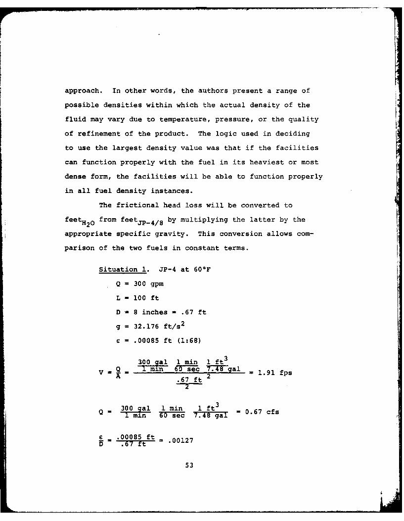
approach. In other words, the authors present a range of
possible densities within which the actual density of the
fluid may vary due to temperature, pressure, or the quality
of refinement of the product. The logic used in deciding
to use the largest density value was that if the facilities
can function properly with the fuel in its heaviest or most
dense form, the facilities will be able to function properly
in all fuel density instances.
The frictional head loss will be converted to
feetH20 from feetj P4/8 by multiplying the latter by the
appropriate specific gravity. This conversion allows com-
parison of the two fuels in constant terms.
Situation 1. JP-4 at 600F
Q = 300 gpm
L = 100 ft
D = 8 inches = .67 ft
g = 32.176 ft/s2
= .00085 ft (1:68)
300 qal 1 min 1 ft3
V .1 m-n 0 -se- c 77T ogal 1.91 fpsA .67 ft 2
2
300 gal 1 min 1 ft3 067 cfs1 min 60 sec 7.48 gal 0
£ _.00085 ftD = .00127
53

= .012~ cn2mft2 1.292 x 10 f 2/s T.-S -C 2 i
(note: 1 stoke =1 c
R = 4Q -C4.67 cfs) = 98548wjrD (1.292 x 10- ft 2 /s)Tr(.67 ft)
f = .0235 (from Diagram 4)
H = f EV2= (.0235) 100 ft 1-9 fs 2L D Tg' -.g~ 2(32.176WTt/s)
= 0.199 ft JP 4 per 100 ft reach
H L = (0.199) (0.801) = 0.159 ftHo0
2IAt this time, calculations will be shown which
reflect the flow of JP-8 at 600F. In order to account for
the increased density of JP-8, the authors used the mass
rate of flow equation (19:122):
in = pAy
where
m=mass rate of flow, slugs/sec
p = density, slugs/ft3
A = pipe cross-sectioned area, ft 2
V - fluid velocity, fps
54

Since the mass rate of flow does not vary between use of JP-4
and JP-8, we can assume the following:
(pAV)JP_4= (PAV) jp_8
The cross-sectioned area will remain constant leaving the
following relationship:
(PV)jp 4 =(PV)
or,
V (PV)JP-4JP_8 -PJP-8
The remainder of the calculations are similar to those of
Situation 1 and thus require no explanation at this point.
Situation 2. JP-8 at 60OF
L = 100 ft
D = 8 inches = .67 ft
g = 32.176 ft/s2
£ = .00085 ft
= (1.553 slugs/ft3) (1.91 fps) = 1.83 fps1.625 slugs/ft 3
AV = 2r (1.83 fps) = 0.645 cfs
C = .00085 ft6 7-rt .00127D .755
55

2 un 2 f 2 -
cm 1 in 1 ft 2 2.260x10 ft2/ss 2.54 cm in
(note: 1 stoke = 1
R 4Q - 4(.0645 cfs) = 54236u D (2.260 x lo- 5 ft2/s)7r(.67 ft)
f .0247 (from Diagram 4)
H E = (.0247) 100 ft 1.83 fps 2
L D (0 .67 ft 2(32.176 ft/s 2
= 0.192 ftjp 8 per 100 ft reach
HL = 0.161 ftH20
Calculations will now be shown for each of the two
fuel types at -200 F. These calculations are similar to
those of Situations 1 and 2, respectively, with the exception
that the values for the density and kinematic viscosity will
change to reflect the decrease in temperature from 60°F to
-200F. The corresponding increase in density will affect
the velocity of the fluid in accordance with a relationship
similar to that which was derived earlier from the mass rate
of flow equation:
(PV 60oF= P 20OF
56

The change in the value of the fluid kinematic viscosity
will affect the value of the Reynolds Number and will, in
turn, cause the dimensionless friction factor to vary.
Situation 3. JP-4 at -20OF
L = 100 ft
D = 8 inches = .67 ft
g = 32.176 ft/s2
e = .00085 ft
3(1.553 slugs/ft3) (1.91 fps) = 1.89 fps(1.571 slugs/ft3)
2.67 ftQ = AV = . 2 (1.89 fps) = 0.666 cfs
= .00085 ft 00127D .67 ft
cm2 1 in 2 1 ft 2 5 2U-= .024- - 2.54 cm i n 2.583 x 10 ft2/s
(note: 1 stoke = 1 --- )
R = 4Q 4(.666 cfs) 48999pwD (2.583 x 10- 5ft2/s)(.67 ft)
f = .0247 (from Diagram 4)
V2 18fs 2
HL =f = (.0247) 100 ft 1.89 f.6 t 2(32.176 ft/s 2
- 0.204 ftjp_4 per 100 ft reach
57

H = 0.165 ftH 0
Situation 4. JP-8 at -20OF
L = 100 ft
D = 8 inches = .67 ft
g = 32.176 ft/s2
= .00085 ft
= (1.625 slugs/ft 3 ) (1.83 fps) 1.82 fps-20-F (1.635 slugs/ft3
Q = = .67 ft (1.82 fps) = 0.64 cfs
.00085 ft 00127D -. 67 ft =.02
2 2 2u .075 cm 1 in 1 ft 8073 x 10 5 ft 2/ss 2.5 12i = 87 I
c2
(note: 1 stoke = 1
4Q 4(0.64 cfs) = 15065prD (8.073 x 10⁻⁵ft 2/s)w(.67 ft)
f = .0305 (from Diagram 4)
L V2 100 ft 1.82 fps2H L = f 1 F yg (.0305) .67 2(32.176 ft/s2 )
0.234 ftjp 8 per 100 ft reach
HL = 0.197 ftH 0
58
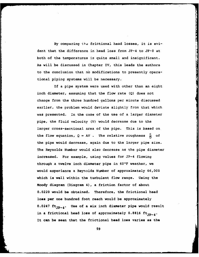
By comparing Ola frictional head losses, it is evi-
dent that the difference in head loss from JP-4 to JP-8 at
both of the temperatures is quite small and insignificant.
As will be discussed in Chapter IV, this leads the authors
to the conclusion that no modifications to presently opera-
tional piping systems will be necessary.
If a pipe system were used with other than an eight
inch diameter, assuming that the flow rate (Q) does not
change from the three hundred gallons per minute discussed
earlier, the problem would deviate slightly from that which
was presented. In the case of the use of a larger diameter
pipe, the fluid velocity (V) would decrease due to the
larger cross-sectional area of the pipe. This is based on
the flow equation, Q = AV . The relative roughness i of
the pipe would decrease, again due to the larger pipe size.
The Reynolds Number would also decrease as the pipe diameter
increased. For example, using values for JP-4 flowing
through a twelve inch diameter pipe in 600 F weather, we
would experience a Reynolds Number of approximately 66,000
which is well within the turbulent flow range. Using the
Moody diagram (Diagram 4), a friction factor of about
0.0220 would be obtained. Therefore, the frictional head
loss per one hundred foot reach would be approximately
0.0247 ftJp_ 4. Use of a six inch diameter pipe would result
in a frictional head loss of approximately 0.8816 ftJP_ 4.
It can be seen that the frictional head loss varies as the
59
diameter of the pipe is changed and, therefore, it is
suggested that this head loss be calculated to suit the
reader's needs in accordance with the particular pipe size
with which he is concerned.
Pump system analysis. Of primary concern in the analysis of
a pump system used to transport a fluid is the amount of
energy required to force the fluid to flow at, or in excess
of, a minimum required flow rate. Some energy may be
supplied by a pressure head as a result of the fluid having
some height or elevation, at the upstream end of the pipe
system, above the height of the fluid discharge point. The
remainder of the energy must be supplied by a pump or pump
system. This energy is represented by the symbol E inpBernoulli's equation, as discussed below.
If this analysis shows that there is a significant
difference in the energy required to pump JP-8 as opposed to
JP-4, further analysis will be required to determine if the
present pumps will be adequate to supply the needed energy.
If the present pumps are found to not be adequate, the
authors will conclude that modifications of the pumping sys-
tem are necessary. If, on the other hand, it is found that
the pumps are adequate to provide the additional energy or
that there is, indeed, no significant difference in the
energy required to pump JP-8 as opposed to JP-4, the authors
60
I

will conclude that no modifications to the present pumping
system are necessary.
In this analysis of the pumping system, the most
important factor to consider is the required increase in
head, as produced by the pump system, to maintain the mini-
mum fuel flow rate of three hundred (300) gpm. To avoid
unnecessary repetitious calculations, the authors have
analyzed the pumping system using a hypothetical system.
This system is designed as a "worst" case system in that the
level of fluid in the tank is assumed to be virtually zeroP1
so that the corresponding head (-) does not help to forceY
the fluid through the pipe. Therefore, the value for Z1
is zero (0). As with the analysis of the fuel flow in the
pipe network, four situations will be presented here
corresponding to the analysis of each of the two fuel types
of both 60OF and -200F. In this analysis, the authors will
use the Bernoulli Equation:
+1 2 + PMP2 +cV2 2+ +H_7+ + 1 7 - 2 +f + Hm (19:142)
where
P - gage pressure at points 1 and 2 , respec-
tively, lbs/ft2
y - specific weight of the fluid, lbs/ft3
a - dimensionless kinetic energy correction factor
V - fluid velocity at points 1 and 2 , respec-
tively, fps
61

Z = height of the fluid above a predetermined datum
at points 1 and 2 , respectively, ft
Ep = head added to the flow by the pump between
points 1 and 2 , ft
Hf = frictional head loss, ft
Hm = minor head losses, ft
(refer to Diagram 5).
For the purpose of this analysis, the values for
both P1 and P2 will be zero (0) lbs/ft2 due to the fact that
both locations are vented to the atmosphere. The value for
V1 will also be zero (0) fps since the surface of the fluid
moves so slowly when compared to the velocity of the flow
in the pipe system. The value for - is normally assumed to
equal one (1) for turbulent flow and two (2) for laminar
flow (2:141). As before, g is a constant with a value of
32.176 ft/s 2. The value of E is that which is sought. Thep
velocity of the flow exiting the pipe system at point 2 is
represented by V2. Z2 was chosen by the authors to represent
the elevation datum and thus has a value of zero (0) feet.
When multiplied by the length of pipe (measured in hundreds
of feet) through which the fluid flows, the frictional head
loss, calculated in the analysis of pipe flow, may be used
for Hf.
62
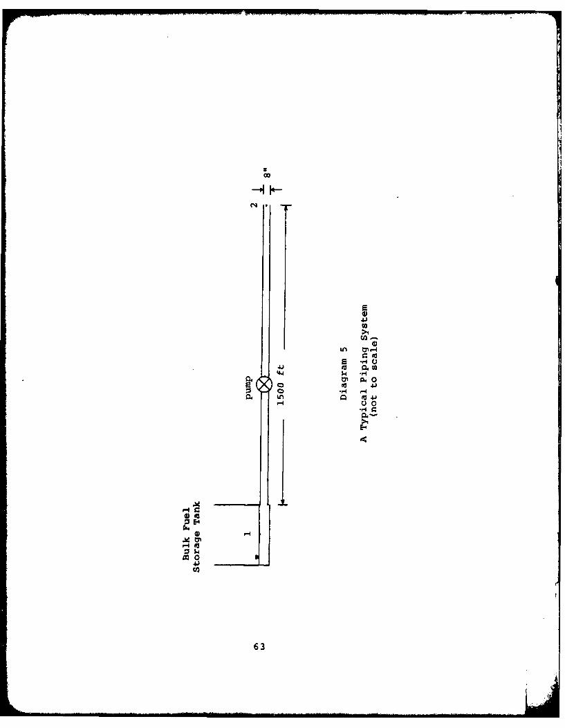
C~4
E
>4
cn-Ln 0
444 W- .-0yl A Q0
04~
p.E-4
E4
9A 0
63

At this time, calculations for analyzing the pump
system energy will be shown. The energy provided by the
pump is converted to feet of water by multiplying the head
(in feet of JP-4/8) by the specific gravity of the fuel.
Situation 1. JP-4 at 60OF
D = 8 inches = .67 ft2.672
A=Tr 2 = 7.7 = 0.3491 ft2
Q = 300 gpm
300 gal 1 min 1 ft3
v Q 7.48 al = 1.913 fpsA 0.3491 ft2
L = 1500 ft
Hf = 0.199 ftjp_4 per 100 ft of reach
(minor losses neglected)
--7 + vi + Z1 + Ep = 2 + -2 + Z2 + Hf
p =0- 1 ' -PI=
V1 =0l= 0
P2 0
Z2=0
thus,
Ep 1.913 fps2 + 15 (.199 ft/100 ft)2(32.176 ft/sec
64

Ep 3.042 ftjp_ 4
or
Ep = (3.042 ftjp_ 4) (0.8 01) = 2.437 ftH 20
Calculations for the next three Situations follow the same
format as Situation 1 and are therefore self-explanatory.
All Situations are subject to the same assumptions.
Situation 2. JP-8 at 60OF
D = .67 ft
A = 0.3491 ft2
Q = 300 gpm
= .lI. (1.553)(1.913) = 1.828 fps2 P2 1.625
L = 1500 ft
Hf = 0.192 ftjp_8 per 100 ft of reach
(minor losses neglected)
2
f
v2 2
= 1 8 fps2 + 15 (.192) = 2.932 ftjp_8
E - 2(32.176 ft/s 2)
- 2.457 ftH20
65
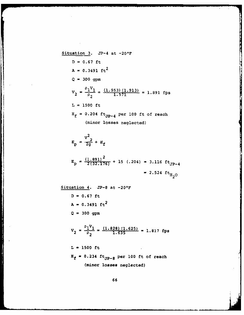
Situation 3. JP-4 at -20OF
D = 0.67 ft
A = 0.3491 ft 2
Q = 300 gpm
= 1IY = (1.553) (1.913) -1.891 fps2 1 21.571
L =1500 ft
H f =0.204 ft JP 4 Per 100 ft of reach
(minor losses neglected)
V2
E -F2+HP f
E = (1.891) 2 + 5(.204) =3.116 ft~p
=2.524 ftH 20
Situation 4. JP-8 at -20OF
D = 0.67 ft
A = 0.3491 ft 2
Q = 300 gpm
- p1V 1 =(1.828) (1.625) =1.817 fps2 2 1.635
L - 1500 ft
H f =0.234 ftjp_8 per 100 ft of reach
(minor losses neglected)
66

V22
Ep = -2-+ Hf
E=(1.817)2Ep = 2(. 1 7) + 15 (.234) = 3.561 ft
= 3.002 ftH 20
A comparison of the values for the energy required of
the pumps show that no significant difference exists between
the energy required to pump JP-4 and that required to pump
JP-8. This holds for both warm and cold weather flow. This
leads the authors to conclude that, as with the piping system,
no modifications to the current pumping system will be nec-
essary. Chapter 4 contains a full discussion of this con-
clusion.
67

Chapter 4
CONCLUSIONS AND RECOMMENDATIONS
Conclusions drawn from, and recommendations made on,
the analysis presented in Chapter 3 is the subject of this
chapter. First, in-depth conclusions will be drawn in
accordance with the Research Objectives, the Research
Questions, and the analysis presented in Chapter 3. The
conclusions will be presented in two separate sections, the
first dealing with the storage facilities and the second
dealing with the transportation facilities. Next, recommen-
dations for future study will be made by the authors and will
be presented as a singular unit. The recommendations section
will serve to provoke interest and research in areas related
to but not covered in this thesis effort.
Storage
Hydrostatic effect. Based on the analysis portion of
Chapter 3 regarding the hydrostatic effect, this thesis team
must conclude that no modification need be made to the tank
shell should a conversion to JP-8 be made. The analysis is
further substantiated by Mr. Frank Morse of the Air Force
POL Technical Assistance Team. Mr. Morse concurs with the
findings of this thesis as regards tank shell thickness
68

sufficiency (15). In a letter dated 8 May 1980, Mr. Morse
stated that no modification need be made in this area.
Further study in this area may well direct itself
towards an analysis of various other regions of the tank
which may be affected by hydrostatic pressure. These other
regions include such items of design as the bottom plates,
the vertical and horizontal joints and bolted door sheets
to mention a few. A study of these items should include an
analysis of hydrostatic pressure at each level of interest
and the capacity of the above listed items to withstand the
additional pressure produced by JP-8 at the various levels.
Foundation analysis. This thesis team concludes that no
modification of the existing foundation is required based on
the analysis findings regarding the critical depth in the
foundation section of Chapter 3. Although the critical depth
does increase, this increase is considered to be insignifi-
cant because of its magnitude. When considering this last
sentence, one must keep in mind that the science of soil
mechanics does have its limitations. Perhaps the greatest
limiting effect arises from the assumption that soil is an
idealized homogeneous material. This assumption is made in
most areas of soil mechanics including that area utilized
in this analysis. Of course, soil is not a homogeneous
material and any analysis will vary in its accuracy according
to just how close to a homogeneous material the soil is (10).
69

These last few statements should have convinced the reader
that soil mechanics is not as exact a science as many would
like. Still, it is the best science available and has been
proven to be remarkably accurate (10). Then, with a grasp
on the limitations of soil mechanics, one can realize that
a difference in critical depth of only two feet is indeed
insignificant. As in the previous section, Mr. Frank Morse,
the lead engineer of the Air Force POL Technical Assistance
Team, again concurs with the findings presented in this
thesis (15).
The recommendations for further study in this sec-
tion are virtually limitless but have been narrowed to those
listed below. These recommendations are limited to the
area of subsurface analysis. Two areas in particular can be
given extremely detailed consideration. The first of these
areas is the shear strength of each layer of soil beneath
the tank structure within range of the critical depth. The
second area involves a study of the settlement characteris-
tics of each layer of soil within range of the critical
depth. The most practical approach to an analysis of the
above mentioned areas would involve the use of shear and
settlement tests in a soils laboratory. Of course, in order
to 1 rform such tests, soil borings must be taken to a level
at least as deep as the critical depth so that soil samples
can be gained from each affected soil layer.
70

Transportation
In this section, the conclusions drawn from the
analysis of the transportation facilities will be discussed.
This section will be divided into two parts. The first part
will cover the discussion of the conclusions drawn from the
analysis of the frictional head loss which occurs in the
piping system, as presented in Chapter 3. The second part
of this section will cover the conclusions drawn from the
analysis of the energy required of the pumping system, also
as presented in Chapter 3.
Pipe system analysis. Upon close examination of the fric-
tional head losses, as calculated in Chapter 3, for warm
weather flow of both JP-4 and JP-8, the reader can see that
the actual difference between the two is very small. Calcu-
lations reveal that there is only a 1.3% increase in the
frictional head loss, as measured in feetH20, of JP-8 as
compared to the head loss associated with JP-4. This, in
itself, is a very insignificant increase in head loss. The
insignificance of the increase is magnified by the fact that
the head loss due to friction is so small to begin with.
When looking at the two fuels in cold weather conditions we
see that there is a 19.4% increase in frictional head loss
associated with the use of JP-8 as opposed to the use of
JP-4. While this is a seemingly large change in head loss,
the reader is reminded to keep in mind the magnitude of the
71
. .. .. .. .. . ... . .. ... . .. . .. ... .. . . . ..... ... ... ... Ii I | . .. .. . ... . . .. . . .. . . . . . . .. • . .. .. ... ... . . ... .. r . ..

actual values of the head losses. In the case of cold
weather flow of JP-4, the head loss per one hundred feet of
reach is 0.165 ftH20 and that of JP-8 is 0.197 ftH20. The
head loss of JP-4 (0.165 ftH2O) converts, roughly, to two
inches of head loss which is quite insignificant. The
authors are, therefore, led to conclude that no modifications
of the present piping system are necessary. These conclu-
sions do not necessar.ly apply when analyzing a pipe system
with a diameter other than eight inches.
Pump system analysis. At this time, the authors will discuss
their conclusions concerning the analysis of the pumping
system as presented in Chapter 3. As was the case in the
analysis of the piping system, the reader can see that there
is only a very insignificant difference between the energy
required to pump JP-8 under warm weather conditions as
opposed to the energy required to pump JP-4 under similar
conditions. In fact, when comparing the appropriate values
as measured in feetH20, it can be seen that there is only a
0.8% increase in energy required to pump JP-8 instead of
JP-4. Not only is this increase in required energy small,
but so are the actual energy values. For example, warm
weather flow of JP-4 required energy amounting to only
2.437 ft 20 which is, in itself, a small load for a pump
installed in such a fuel storage and transportation facility.
While the increase in energy required for cold weather flow
72

of JP-8, compared to that of JP-4, is 18.9%, the reader must,
as discussed before, take into consideration the magnitude
of the actual values. For instance, cold weather flow of
JP-4 requires approximately 2.524 ftH20 of energy while flow
of JP-8, under similar conditions, requires 3.002 ftH20.
As stated above, these loads are quite insignificant com-
pared to the capacity of a pump installed for such a purpose
as pumping large quantities of fuel. The authors, there-
fore, conclude that no modifications, or construction, to
the present pumping facilities will be necessary.
The conclusions drawn by the authors are substan-
tiated by Mr. Frank Morse, the lead engineer of the Air
Force POL Technical Assistance Team at Kelly AFB, Texas.
In a letter to this thesis team, dated 8 May 1980, Mr. Morse
explained that no modifications would be necessary to
existing facilities (15). These conclusions eliminate the
need for concern about construction of new facilities, or
modifications to the present facilities, and the lead time
associated with the acquisition of the materials necessary
for such construction. These conclusions also eliminate the
need for concern about the management of fuel disbursement
during the construction process as well as the training of
personnel to operate and maintain the new facilities. While
these are only a sampling of the areas that would normally
be affected by the need for modifications of the facilities,
the list is by no means complete and is offered for the sole
73

purpose of giving the reader some idea of what the magnitude
of the problem would have been like had the modifications
been necessary.
Further Recommendations
The authors recommend several areas related to this
thesis effort which may be studied in the future. Included
are studies concerning the analysis of underground type fuel
storage tanks. These tanks, unlike those studied in this
thesis, are located below ground level and, therefore, may
possess unique problems as regards fuel conversion, not only
in the storage area but also in the area of pipes and pumps.
Another area of interest involves fire safety. A detailed
analysis of the possible safety advantages to be gained by
converting to JP-8 would make for an interesting topic of
study. It is suggested that this study revolve around the
use of JP-8 in facilities discussed in this thesis.
Finally, a study could be conducted to cover the
possible design of a more efficient pump system for the sake
of conserving some of the energy required to operate them.
This study could be expanded to include a study of the
relationship between the height of fluid in the bulk storage
tank and the energy required to maintain the minimum flow
rate in the pipe system. This may involve a determination
of the feasibility of replacing the current pump system with
a series of valves or less energy consuming pumps.
74
I
APPENDIX A
OPERATIONAL DEFINITIONS
75

Aircraft turbine fuel is the fuel used in aircraft
powered by turbine or jet engines. One such fuel is JP-4
which is a naptha-based turbine fuel currently used by the
USAF in its aircraft. It contains rust and ice inhibitors.
The other turbine fuels available today are kerosene-based.
These fuels include Jet-A, Jet A-1, JP-5, and JP-8. The
latter two of these fuels contain corrosion and ice inhibi-
tors whereas the first two do not since they are used almost
exclusively in the commercial air industry.
The above mentioned fuels possess certain qualities.
First, the flash point is the lowest temperature at which
the vapor of a combustible liquid can be made to ignite
momentarily in air. The flash point of JP-8, for example,
is much higher than that of JP-4 causing cold start and air
relight problems. Second, volatility is the quality of
evaporating readily at normal temperatures and pressures.
JP-4 is a much more volatile fuel than is JP-8. Third,
viscosity is the degree to which a fluid resists flow under
an applied force. Conversion to JP-8 introduces a viscosity
problem in that as operating temperatures approach (-)200F,
JP-8 becomes very viscous causing pumps and filters to be
strained more than normal. The problem is compounded greatly
as JP-S approaches (-)580F, its freezing temperature.
Another fuel property which should be mentioned is
76

vapor pressure. This is the pressure which is exerted on an
environment by a vapor in equilibrium with a solid or a
liquid at a specified temperature.
One of the most outstanding physical problems
associated with aircraft use of JP-8 is air relight. Air
relight involves reignition of the engine while the aircraft
is in flight. On occasion, aircraft turbine engines have
been known to "flame out," an event marked by a loss of
ignition of the fuel resulting in a loss of thrust. It is
at this point that air relight is required.
When dealing with the bulk storage facilities used
to store the turbine fuel hydrostatic pressure must be
taken into account. Hydrostatic pressure is that pressure
which is exerted by a static liquid on its environment by
virtue of its depth.
A key ingredient in the production of JP-4 turbine
fuel is naptha. Naptha is defined as "any of various vola-
tile often flammable liquid hydrocarbon mixtures used chiefly
as solvents and dilutents and as raw materials for conver-
sion to gasoline [23:1502]."
Soil possesses several characteristics, one of which
is shear strength. This is the ability of the soil to
resist sliding along internal surfaces within its mass.
Shear failure then is an occurrence marked by the sliding
of these internal surfaces. The critical depth of a soil is
that depth at which the pressure exerted by a structure or
77

material on the surface of the soil is negligible (usually
100-200 lbs/square foot) (10). Excessive settlement of a
structure can be considered to be any amount of settlement
incurred which disrupts the normal operating ability or
structural integrity of a facility or structure.
The storage tank used as an example in Chapter 3 is
constructed of courses which are butt-welded together. A
course is simply a series of sheets of steel plate located
at the same elevation around the tank. Stated simply, these
courses can be said to be stacked one on another until the
required tank height is reached. The term "butt-welded"
refers to the way in which the courses are joined. Butt-
welded simply means that the plates of each course were
stacked end to end with no overlapping allowed.
There exist some characteristics and theory about
soil itself which need defining. A homogeneous soil is a
soil which is consistent throughout its mass. That is, it
is not stratefied into layers which possess different
characteristics. An isotropic soil is one which exhibits
equal tendency for compressibility in all directions. When
one assumes that a soil is elastic, he is saying that it is
capable of recovering its original size and shape after
deformation.
The theory of elasticity refers to any soils theory
which assumes that the relationship between stress and s.train
can be defined mathematically.
78
.

SELECTED BIBLIOGRAPHY
79

A. REFERENCES CITED
1. Aeronautical Systems Division, Wright-Patterson AFB OH/CV. Letter, subject: Consequences of PotentialConversion to JP-8 Fuel, to Air Force Systems Command,Andrews AFB MD/SD, no date.
2. Anderson, Major Earle E., USAF. Staff Electronics Engi-neer, Directorate of Engineering and ComputerResources, AFLC/LOE. Briefing on JP-8 Conversionin NATO and CONUS, December 1978.
3. Baxter, Major Edward G., USAF. "Flight Test Report."Published research report No. ASTP 68-9-13,Aeronautical Systems Division, Wright-Patterson AFBOH, February 1969.
4. Beery, G. T., and others. Assessment of JP-8 as aReplacement for the Air Force Standard Jet FuelJP-4: Part 1. Assessment of JP-8/JP-4 Fuel in aNoncombat Environment. Technical Report AFAPL-TR-74-71, Part 1. Wright-Patterson AFB OH, June 1975.
5. Bussy, J. Spokesman, Chicago Bridge and Iron Company,Chicago, Illinois. Telephone interview. November1979.
6. Butchko, Joe. Chief of Fuels Storage, Wright-PattersonAFB OH, Management Services Division, Lear Siegler,Inc. Personal interviews from 18 October 1979 to13 May 1980.
7. Churchill, A. V., and others. "Final Report: FuelsStandardization - Aviation Turbine Fuels."Published research report, unnumbered, Joint Tech-nical Coordinating Group on Fossil Fuels Standardi-zation and Utilization, Wright-Patterson AFB OH,9 September 1976.
8. Dickson, Joseph C., and Louis P. Karvelas. Impact ofFuel Properties on Jet Fuel Availability. TechnicalReport AFAPL-TR-76-7. Wright-Patterson AFB OH,April 1976.
80

9. Egan, Colonel William M., USAF. "Minutes of JP-4 toJP-8 Fuel Conversion Conference." Publishedconference minutes, unnumbered, Air Force LogisticsCommand, Wright-Patterson AFB OH, 1 March 1978.
10. Himelright, L. K. Head, Department of Civil Engineering,The Citadel, Charleston SC. Class notes. September1978 through May 1979.
11. Lowman, Colonel James K., USAF. Assistant DCS/Logistics.Letter, subject: Operational Evaluation/Conversionto JP-8 (NATO F-34), to HQ USAFE, 21 March 1978.
12. Maxson, Major General W. B., USAF, and Brigadier GeneralW. C. Nutt, USAF. "Converting USAF AeronauticalEquipment to JP-8." Published research report,unnumbered, Wright-Patterson AFB OH, 3 May 1978.
13. Moore, Colonel Charlie B., USAF. Briefing on Conver-sion to JP-8.
14. Morris, Henry M., and James M. Wiggert. Applied Hydrau-lics In Engineering. New York: The Ronald PressCompany, 1972.
15. Morse, Frank P. Lead Engineer, Air Force POL TechnicalAssistance Team. Letter, subject: Fuel Conversionfrom JP-4 to JP-8, to Lt Steven M. Pittman,AFIT/LSOG, 7 May 1980.
16. Nutt, Brigadier General Waymond C., USAF. Director ofMaintenance and Supply. Talking paper, subject:Talking Paper on JP-8, from Lt Col Lee, 9 November1978.
17. O'Loughlin, Colonel Earl T., USAF. Deputy Director ofMaintenance, Engineering, and Supply. Letter,subject: Use of F-34 (JP-8) as Primary Fuel forLand Based Jet Aircraft, from Lt Col Gennaci,AF/AGYE, 10 June 1976.
18. Sowers, George B., and George F. Sowers. IntroductorySoil Mechanics and Foundations. New York NY:MacMillan Publishing Company, Inc., 1970.
19. Streeter, Victor L., and E. Benjamin Wylie. FluidMechanics. New York: McGraw-Hill Book Company,1975.
81

20. Terzaghi, Karl, and Ralph B. Peck. Soil Mechanics inEngineering Practice. 2d ed. New York NY: John Wileyand Sons, Inc., 1967.
21. Vennard, John K., and Robert L. Street. ElementaryFluid Mechanics. 5th ed. New York NY: John Wileyand Sons, Inc., 1975.
22. "Welded Steel Tanks for Oil Storage." American PetroleumInstitute, Standard 650, second revision, Washington,D.C., 31 December 1978.
23. West, Captain John, USAF. Directorate of Engineeringand Computer Resources, HQ AFLC, Wright-PattersonAFB OH. Personal interview. 21 November 1979.
B. RELATED SOURCES
Aero Propulsion Laboratory, Air Force Systems Command. Mem-orandum concerning advantages and disadvantages of JP-4and JP-8, Wright-Patterson AFB OH, 1977.
"Alternate Fuels for J79 Engines." Published research report,unnumbered, General Electric Company Aircraft EngineGroup, June 1975.
Bee, Dick. Directorate for Development and Engineering, U.S.Army Aviation Research and Development Command. "Con-version of Army Aeronautical Equipment to JP-8 Fuel."
Brown, R. I. Manager, J79 Technical Programs and Post Pro-duction Support, General Electric Company. Letter,subject: Use of JP-8 Fuel on J79 and J47 Engines,to Oklahoma City Air Logistics Center, Tinker AFB,Oklahoma City, Oklahoma MMPR, 23 September 1976.
Letter, subject: Use of JP-8 Fuel on J79 andJ47 Engines, to OC-ALC, Tinker AFB, Oklahoma City,Oklahoma MMPR, 23 September 1976.
Egan, Colonel William M., USAF. "JP-8 Conversion ProgramReview Conference Minutes (3-4 October 1978)." Pub-lished conference minutes, unnumbered, Air ForceLogistics Command, Wright-Patterson AFB OH, 27 October1978.
82

Eodice, Peter P. Chief Systems Engineer, Specialized Air-craft Fighter Attack Program Office. Letter, subject:Use of JP-8 as Primary Fuel for the A-37, to ASD/ENFE(Lt Col J. F. Andrews), 17 March 1976.
Guillory, Colonel, USAF. Briefing on Air Force Position onthe Conversion of USAFE to JP-8, 3 October 1978.
Guthrie, General John R. Commander, U.S. Army MaterielDevelopment and Readiness Command. Letter concerningAir Force timing of the conversion to JP-8 in Europe,to General Frederick J. Kroesen, Vice Chief of Staff,U.S. Army, 22 November 1978.
Hanson, Donald B. Member, JP-8 Ad Hoc Committee. Letter,subject: Qualification of the F100 for Operation onJP-8, to ASD/ENFR (Lt Col Andrews), 15 March 1976.
Headquarters, USAF, Deputy Chief of Staff/Logistics andEngineering. "F-34 (JP-8) Status Report for the Ad HocCommittee on Equipment Interoperability." Publishedresearch report, unnumbered, Air Force LogisticsCommand, Wright-Patterson AFB OH, 20 May 1979.
Hughes, Major Phillip L., USAF. Chief, A-7, C-130 EngineProgram Management Group. Letter, subject: JP-8As a Primary or Interchangeable Fuel, TF41-A-I Engine,to ASD/ENFE (Lt Col J. F. Andrews), 16 March 1976.
Knight, Colonel William J., USAF. Director, InternationalFighter SPO. Letter, subject: F-5/J85 JP-8 PrimaryFuel Considerations, from ASD/ENFE (Lt Col J. F.Andrews), 16 March 1976.
Lowry, Bernard V. Deputy Director, E-3A Air Vehicle Engi-neering. Letter, subject: JP-8 as a Primary or Inter-changeable Fuel for Use in the E-3A Aircraft, to ASD/ENFEF, 17 March 1976.
Mason, Danny J. Chief Propulsion and Power Engineer, E-4Project Engineering Office. Letter, subject: Jet Fuelfor E-4 Aircraft, to ASD/ENFEF (Mr Lyle), 4 March 1976.
Office of the Under Secretary of the Air Force. Memorandumon Use of F-34 (JP-8) as Primary Fuel for Land BasedJet Aircraft, 14 June 1976.
Paris, Bob L. Chief, Propulsion and Power Division, Direc-torate of Systems Engineering, Deputy for A-10. Letter,subject: Conversion of A-10 to JP-8 Fuel, to ASD/ENFE(Lt Col Andrews).
83