Embed Size (px)
Citation preview

A Dynamic Model for Robotic Fish with Flexible Pectoral Fins
Sanaz Bazaz Behbahani, Jianxun Wang, and Xiaobo Tan
Abstract— This paper presents the dynamic modeling, designand fabrication of a free-swimming robotic fish with flexiblepectoral fins. To capture the flexibility of the fins, a multi-segment model with torsional springs and viscous dampers isintroduced and the hydrodynamic force on each segment iscalculated based on the blade element theory. Other forces suchas added mass, quasi-static lift, and drag are also consideredin modeling the dynamics of the robot. A robotic fish hasbeen prototyped, which has a 3D-printed body and a pairof servo-actuated flexible pectoral fins. The proposed dynamicmodel is validated with experiments done on the robotic fish,where the model predictions of forward swimming speeds andsteady turning periods and radii are found to match closely theexperimental measurements when the pectoral fins are actuatedat different frequencies.
I. INTRODUCTION
Zoologists, engineers, and biologists have all examinedfish and other aquatic creatures with intense interest, includ-ing their specific behavior, swimming pattern, high maneu-verability, and efficient design [1]–[5]. In the past decades,several types of underwater vehicles have been developed,ranging from autonomous underwater vehicles [6], to roboticfish that attempt to mimic fish behavior [7]–[12]. Roboticfish can be used to monitor water quality [13], [14], and tointeract with live fish for the studies of fish behavior [15],to name a few. For robotic fish, there are several ways toproduce propulsion, such as using a tail (caudal) fin, pairedpectoral fins, or the combination of both, which are normallyactuated by motors [11], [16]–[24] or different kinds of smartmaterials [7], [25]–[27].
Many species of fish use their pectoral fins to swim,generate thrust, and remain stable during an unexpected flow[28]. While many studies on robotic fish have focused oncaudal fin actuation, there are some investigations relevantto the pectoral fins. Webb [29], [30] and Blake [31], [32]modeled the pectoral fin propulsion and motion of a livefish, providing insight into the calculations of hydrodynamicforces involved in pectoral fin actuation. These are severalstudies on robotic fish with pectoral fins, most of which,however, have considered only rigid pectoral fins [16]–[22],[33].
The case of flexible pectoral fins in robotic fish has beenstudied by several groups. Lauder and coworkers explored
*This work was supported by National Science Foundation (Grant DBI-0939454, CNS-1059373, IIS-0916720 and ECCS-1029683).
S. B. Behbahani, J. Wang, and X. Tan are with the Smart Mi-crosystems Laboratory, Department of Electrical and Computer Engi-neering, Michigan State University, East Lansing, MI 48824, USA.bazazbeh @ msu.edu (S. B. Behbahani), wangji19@ msu.edu (J. Wang), xbtan @ msu.edu (X. Tan).
Send correspondence to X. Tan. Tel: 1-517-432-5671; Fax: 1-517-353-1980.
the hydrodynamics associated with pectoral fins experimen-tally [34], [35] and with Computational Fluid Dynamics(CFD) simulation. Deng et al. [23], [36], modeled a roboticfish with two pectoral fins and a caudal fin, and used it todesign controllers. However, the flexibility of the pectoralfins in their experimental prototype was not accommodatedin their model. With CFD simulation, Shoele et al. [37]numerically examined the fluid-structure interaction andforce generation by pectoral fins of a fish during labriformswimming. Palmisano et al. [38] studied a pectoral fin withflexible rays in a flapping motion and used CFD analysis tooptimally design the fin. In summary, while flexibility is animportant characteristic of pectoral fins for live fish fins andis expected to significantly influence the hydrodynamics ofrobotic fish with pectoral fins, relevant studies have mostlyfocused on experimental or CFD exploration. A non-CFDdynamic model that accommodates pectoral fin flexibilitywill be instrumental in the design and control of such robots,and this is the contribution of the current paper.
In this paper we present a dynamic model for a roboticfish propelled by a pair of flexible pectoral fins. The robotbody is modeled as a rigid body surrounded by inviscid,incompressible fluid, and the flexible pectoral fins are ap-proximated with a number of rigid segments connectedthrough torsional springs and dampers. The hydrodynamicforce produced by an individual segment of a pectoral finis calculated based on the blade element theory, in whicheach segment is divided into a number of blades and thehydrodynamic force is evaluated for each blade element [4].We also conduct experiments on a prototyped robotic fish toevaluate the presented model and compare the simulationand experimenal results. Specifically, we have consideredthe forward swimming motion, where both fins are actuatedsymmetrically with a faster power-stroke movement than arecovery stroke, and the turning motion, where only of thefins is actuated. It is found that the model predictions of theforward swimming speed and the steady turning radius andperiod match closely the experimental measurement.
This paper is organized as follows. In Section II, thedynamic model of the robotic fish actuated by a pair of flex-ible pectoral fins is presented. In Section III, the prototypedrobotic fish is described, and the experimental validationof the model is presented. Section IV provides concludingremarks, including the discussions on future work.
II. SYSTEM MODELING
In this work, the robotic fish is modeled as a rigid bodywith flexible pectoral fins surrounded by inviscid, incom-pressible fluid. As shown in Fig. 1, there are three motions
2013 IEEE/ASME International Conference onAdvanced Intelligent Mechatronics (AIM)Wollongong, Australia, July 9-12, 2013
978-1-4673-5320-5/13/$31.00 ©2013 IEEE 1552
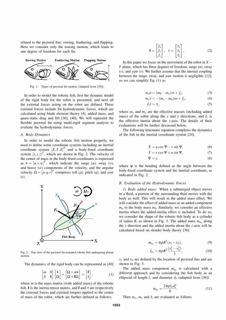
related to the pectoral fins: rowing, feathering, and flapping.Here we consider only the rowing motion, which leads toone degree of freedom for each fin.
Fig. 1. Types of pectoral fin motion (Adapted from [39]).
In order to model the robotic fish, first the dynamic modelof the rigid body for the robot is presented, and next allthe external forces acting on the robot are defined. Theseexternal forces include fin hydrodynamic forces, which arecalculated using blade element theory [4], added mass, andquasi-static drag and lift [36], [40]. We will represent theflexible pectoral fin using multi-rigid segment analysis toevaluate the hydrodynamic forces.
A. Body Dynamics
In order to model the robotic fish motion properly, weneed to define some coordinate systems including an inertialcoordinate system [X ,Y,Z]T and a body-fixed coordinatesystem [x,y,z]T , which are shown in Fig. 2. The velocity ofthe center of mass in the body-fixed coordinates is expressedas v = [u,v,w]T , which indicate the surge (u), sway (v),and heave (w) components of the velocity, and the angularvelocity Ω = [p,q,r]T comprises roll (p), pitch (q), and yaw(r).
Fig. 2. Top view of the pectoral fin-actuated robotic fish undergoing planarmotion.
The dynamics of the rigid body can be represented as [40][m 00 I
][vΩ
]+
[Ω×mvΩ× IΩ
]=
[fτ
], (1)
where m is the mass matrix (with added mass) of the roboticfish, I is the inertia tensor matrix, and f and τ are respectivelythe external forces and external torques applied to the centerof mass of the robot, which are further defined as follows:
f =
fxfyfz
, τ =
τxτyτz
. (2)
In this paper we focus on the movement of the robot in X−Y plane, which has three degrees of freedom, surge (u), sway(v), and yaw (r). We further assume that the inertial couplingbetween the surge, sway, and yaw motion is negligible [12],so we can simplify Eq. (1) as
mxu = (mb−my)vr+ fx, (3)myv =−(mx−mb)ur+ fy, (4)Izr = τz. (5)
where mx and my are the effective masses (including addedmass) of the robot along the x and y directions, and Iz isthe effective inertia about the z-axis. The details of theirevaluations will be further discussed below.
The following kinematic equation completes the dynamicsof the fish in the inertial coordinate system [24].
X = u cos Ψ− v sin Ψ, (6)Y = v cos Ψ+u sin Ψ, (7)
Ψ = r, (8)
where ψ is the heading defined as the angle between thebody-fixed coordinate system and the inertial coordinate, asindicated in Fig. 2.
B. Evaluation of the Hydrodynamic Forces
1) Body added mass: When a submerged object movesin a fluid, a portion of the surrounding fluid moves with thebody as well. This will result in the added mass effect. Wewill consider the effect of added mass as an added componentma to the body mass mb. Similarly, we consider an effectiveinertia where the added-inertia effect is included. To do so,we consider the shape of the robotic fish body as a cylinderof radius R, as shown in Fig. 3. The added mass may alongthe y direction and the added inertia about the z-axis will becalculated based on slender body theory [36]
may = πρR2(x1− x2), (9)
Iaz = πρR2 (x31− x3
2)
3, (10)
x1 and x2 are defined by the location of pectoral fins and areshown in Fig. 3.
The added mass component max is calculated with adifferent approach and by considering the fish body as anellipsoid of length le and diameter de (adapted from [36])
max =2πρled2
e
6. (11)
Then mx, my and Iz are evaluated as follows
1553
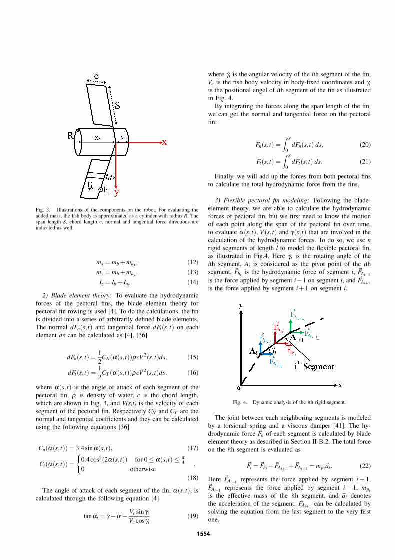
Fig. 3. Illustrations of the components on the robot. For evaluating theadded mass, the fish body is approximated as a cylinder with radius R. Thespan length S, chord length c, normal and tangential force directions areindicated as well.
mx = mb +max , (12)my = mb +may , (13)
Iz = Ib + Iaz . (14)
2) Blade element theory: To evaluate the hydrodynamicforces of the pectoral fins, the blade element theory forpectoral fin rowing is used [4]. To do the calculations, the finis divided into a series of arbitrarily defined blade elements.The normal dFn(s, t) and tangential force dFt(s, t) on eachelement ds can be calculated as [4], [36]
dFn(s, t) =12
CN(α(s, t))ρcV 2(s, t)ds, (15)
dFt(s, t) =12
CT (α(s, t))ρcV 2(s, t)ds, (16)
where α(s, t) is the angle of attack of each segment of thepectoral fin, ρ is density of water, c is the chord length,which are shown in Fig. 3, and V(s,t) is the velocity of eachsegment of the pectoral fin. Respectively CN and CT are thenormal and tangential coefficients and they can be calculatedusing the following equations [36]
Cn(α(s, t)) = 3.4sinα(s, t), (17)
Ct(α(s, t)) =
0.4cos2(2α(s, t)) for 0≤ α(s, t)≤ π
40 otherwise
.
(18)
The angle of attack of each segment of the fin, α(s, t), iscalculated through the following equation [4]
tanαi = γ− ir− Vc sinγi
Vc cosγi(19)
where γi is the angular velocity of the ith segment of the fin,Vc is the fish body velocity in body-fixed coordinates and γiis the positional angel of ith segment of the fin as illustratedin Fig. 4.
By integrating the forces along the span length of the fin,we can get the normal and tangential force on the pectoralfin:
Fn(s, t) =∫ S
0dFn(s, t) ds, (20)
Ft(s, t) =∫ S
0dFt(s, t) ds. (21)
Finally, we will add up the forces from both pectoral finsto calculate the total hydrodynamic force from the fins.
3) Flexible pectoral fin modeling: Following the blade-element theory, we are able to calculate the hydrodynamicforces of pectoral fin, but we first need to know the motionof each point along the span of the pectoral fin over time,to evaluate α(s, t), V (s, t) and γ(s, t) that are involved in thecalculation of the hydrodynamic forces. To do so, we use nrigid segments of length l to model the flexible pectoral fin,as illustrated in Fig.4. Here γi is the rotating angle of theith segment, Ai is considered as the pivot point of the ithsegment, ~Fhi is the hydrodynamic force of segment i, ~FAi−1
is the force applied by segment i−1 on segment i, and ~FAi+1is the force applied by segment i+1 on segment i.
Fig. 4. Dynamic analysis of the ith rigid segment.
The joint between each neighboring segments is modeledby a torsional spring and a viscous damper [41]. The hy-drodynamic force ~Fh of each segment is calculated by bladeelement theory as described in Section II-B.2. The total forceon the ith segment is evaluated as
~Fi = ~Fhi +~FAi+1 +
~FAi−1 = mpi~ai. (22)
Here ~FAi+1 represents the force applied by segment i + 1,~FAi−1 represents the force applied by segment i− 1, mpi
is the effective mass of the ith segment, and ~ai denotesthe acceleration of the segment. ~FAi+1 can be calculated bysolving the equation from the last segment to the very firstone.
1554
The moment on each segment resulting from hydrody-namic forces relative to its pivot point Ai can be calculatedas follows
~Mhi =∫ l
0~ri×~Fhi , (23)
where~ri is the position vector of each segment pointing fromthe base point of the pectoral fin to the point Ai.
The spring-damper moment is calculated as [24]
~M(S+D)i = [−KS(γi− γi−1)−KD(γi− γi−1)] (24)
Here KS and KD are the spring and damping coefficients.For a uniformly discretized rectangular beam, KS can beevaluated based on the properties of each segment [41]
KS =Edh3
12l, (25)
where h is the thickness of each segment, l is the length ofeach segment, d is the width of the segment, and E is theYoung’s modulus of the flexible material used for the pectoralfin. The damping coefficient KD is obtained by parameteridentification and assumed to be a constant [24].
The total moment equation for each segment relative topoint Ai is written as
~Mhi +~ri×~FAi+1 +~M(S+D)i =−Ipγi, (26)
where Ip is the effective inertia of each segment and γi isthe angular acceleration of each segment. In all of the aboveequations mp and Ip are evaluated as
mp = madded +mpec f in =14
ρπl2c+mpec f in, (27)
Ip =13
mpec f inl2. (28)
Here l is length of each segment, c is the chord length andmpec f in is the mass of each segment of the pectoral fin.
With Eq. 20, 21, 22, and 26, the dynamics of the finsegments and their resulting hydrodynamic forces are fullydescribed.
4) Body drag and lift: Besides the hydrodynamic forcesof pectoral fins, there are body lift force FL , drag force FDand drag moment MD acting on the robotic fish [42]
FD =12
ρ|VC|2SACD, (29)
FL =12
ρ|VC|2SACLβ , (30)
MD =−CMω2z sgn(ωz), (31)
where SA is the characteristic area of the robot, CD is thedrag force coefficient, CL is the lift force coefficient, CM isthe drag moment coefficient, VC is the linear velocity of thebody, β is the angle of attack of the robot body, ωz is theangular velocity of the body about z direction (element r ofthe vector Ω), and sgn is the sign function.
The terms fx, fy and τz in Eq. 3, 4, 5 are then evaluatedas
fx = Fhx −FD cos β +FL sin β , (32)
fy = Fhy −FD sin β −FL cos β , (33)
τz = Mh +MD, (34)
where Fhx and Fhy are the total hydrodynamic forces gener-ated by pectoral fins in x and y direction, and Mh is the totalhydrodynamic moment applied to the center of the body andcan be calculated as follows
~Mhr =~rCr ×~F0r (35)
Here ~rCr denotes the vector from the body center C to thebase of the right pectoral fin and ~F0r is the total forcegenerated by the right pectoral fin excerted to the body atthe base of pectoral fin. The same procedure results in Mhlfor the left pectoral fin and therefore
~Mh = ~Mhr + ~Mhl . (36)
III. SIMULATION AND EXPERIMENTAL RESULTS
A. Experimental Setup and Parameter Identification
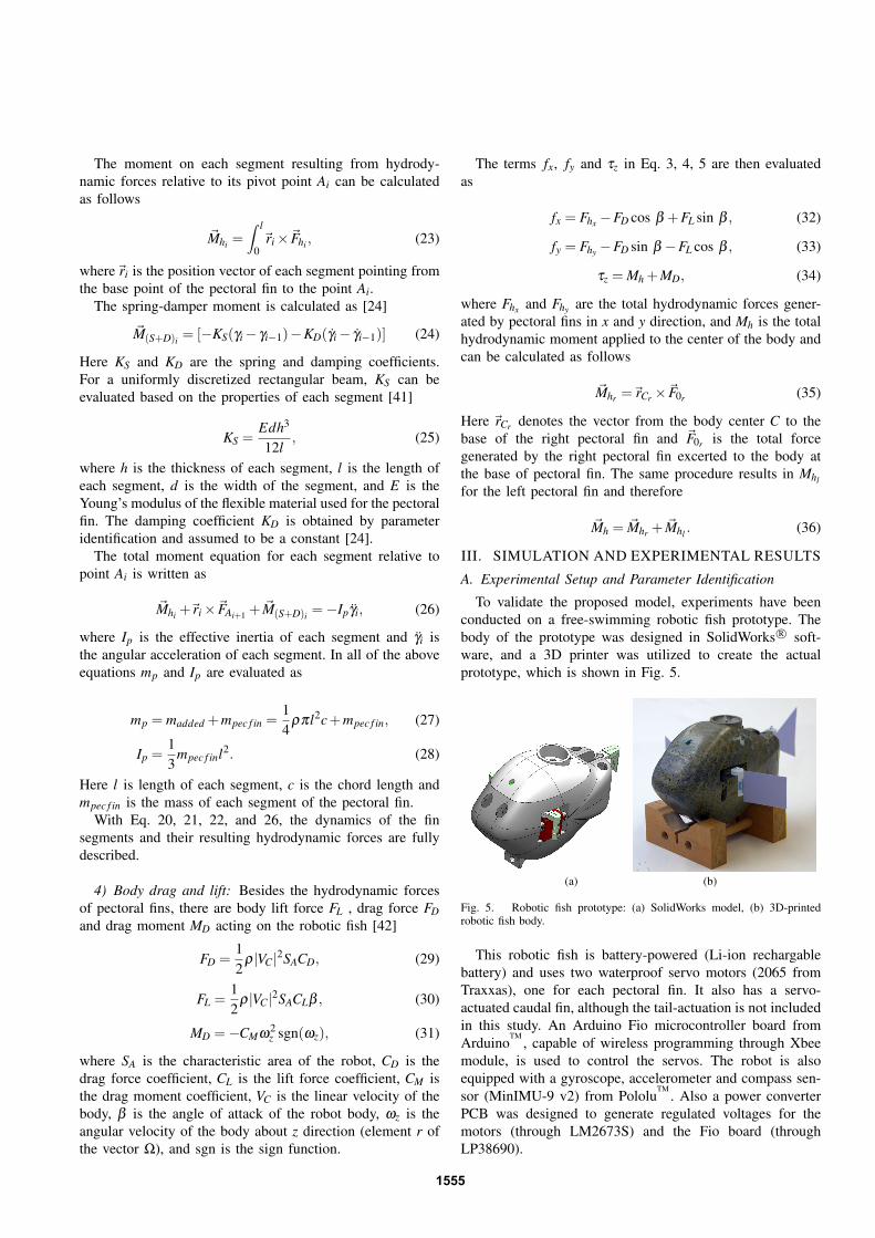
To validate the proposed model, experiments have beenconducted on a free-swimming robotic fish prototype. Thebody of the prototype was designed in SolidWorks R© soft-ware, and a 3D printer was utilized to create the actualprototype, which is shown in Fig. 5.
(a) (b)
Fig. 5. Robotic fish prototype: (a) SolidWorks model, (b) 3D-printedrobotic fish body.
This robotic fish is battery-powered (Li-ion rechargablebattery) and uses two waterproof servo motors (2065 fromTraxxas), one for each pectoral fin. It also has a servo-actuated caudal fin, although the tail-actuation is not includedin this study. An Arduino Fio microcontroller board fromArduino
TM, capable of wireless programming through Xbee
module, is used to control the servos. The robot is alsoequipped with a gyroscope, accelerometer and compass sen-sor (MinIMU-9 v2) from Pololu
TM. Also a power converter
PCB was designed to generate regulated voltages for themotors (through LM2673S) and the Fio board (throughLP38690).
1555
The prototype is capable of using different types ofpectoral fins through the attachement mechanism that isdesigned. The robot is approximately 15 cm long, 12 cmhigh and 6.6 cm wide without the pectoral and caudalfins and weights 0.46 kg. The pectoral fins used for thisexperiment have 4.5 cm span length and 3 cm chord length,and are cut from a flexible plastic material. We approximatedeach flexible pectoral fin with three segments and set KS =5.2× 10⁻³ and KD = 5.7× 10⁻⁴ based on the work donein [24]. The parameters CD = 1.82× 10³, CL = 10.5, andCM = 20.6× 10⁻³ kg.m2 were obtained by fitting the dataof forward velocity versus beating frequency of 1.5 Hz andturning period versus beating frequency of 1.25 Hz and 1.5Hz, as shown in Fig. 6 and Fig. 7, and then applied to thesimulation of all other cases.
To validate the model, we conducted the experimentsbased on different frequencies of fin flapping in forwardswimming and turning. For forward swimming, we useda lower frequency ( 1
5 f ) for fin beat in recovery phase incomparison with fin beat frequency f of the power phase,which resulted a net forward thrust. For turning, we activateonly one of the fins with a similar frequency structure forthe power/recovery strokes.
The experiments were conducted in a tank that measured2 feet wide, 6 feet long, and 2 feet deep. To measure theforward velocity, we timed the fish swimming 0.5 m distancewith a stopwatch. The turning period and the turning radiuswere captured via a stopwatch and a ruler, respectively. Theexperiment for each setting was repeated 10 times.
B. Simulation and Experimental Results
Fig. 6 shows the comparison between the forward veloc-ities of the robotic fish measured from the experiment andpredicted by the proposed model. We changed the flappingfrequency of the power stroke phase of pectoral fin motionto study its effect on the forward velocity. As shown in thefigure, the forward velocity will increase when the fins flapfaster, and this trend is supported by our simulation data.
Fig. 6. Model predictions of the robot swimming velocity versus theexperimental measurements, for different fin actuation frequencies.
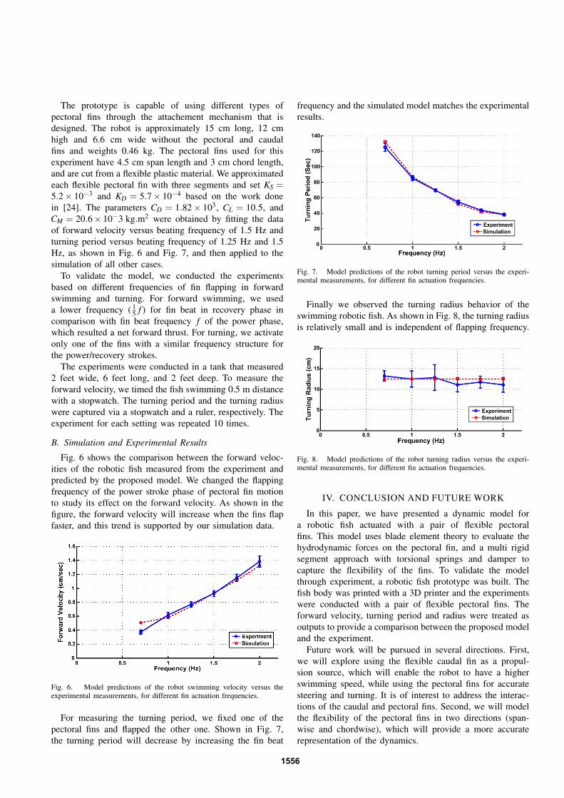
For measuring the turning period, we fixed one of thepectoral fins and flapped the other one. Shown in Fig. 7,the turning period will decrease by increasing the fin beat
frequency and the simulated model matches the experimentalresults.
Fig. 7. Model predictions of the robot turning period versus the experi-mental measurements, for different fin actuation frequencies.
Finally we observed the turning radius behavior of theswimming robotic fish. As shown in Fig. 8, the turning radiusis relatively small and is independent of flapping frequency.
Fig. 8. Model predictions of the robot turning radius versus the experi-mental measurements, for different fin actuation frequencies.
IV. CONCLUSION AND FUTURE WORK
In this paper, we have presented a dynamic model fora robotic fish actuated with a pair of flexible pectoralfins. This model uses blade element theory to evaluate thehydrodynamic forces on the pectoral fin, and a multi rigidsegment approach with torsional springs and damper tocapture the flexibility of the fins. To validate the modelthrough experiment, a robotic fish prototype was built. Thefish body was printed with a 3D printer and the experimentswere conducted with a pair of flexible pectoral fins. Theforward velocity, turning period and radius were treated asoutputs to provide a comparison between the proposed modeland the experiment.
Future work will be pursued in several directions. First,we will explore using the flexible caudal fin as a propul-sion source, which will enable the robot to have a higherswimming speed, while using the pectoral fins for accuratesteering and turning. It is of interest to address the interac-tions of the caudal and pectoral fins. Second, we will modelthe flexibility of the pectoral fins in two directions (span-wise and chordwise), which will provide a more accuraterepresentation of the dynamics.
1556
ACKNOWLEDGMENT
The authors would like to thank Prof. Philip K. McKinleyfor his helpful discussions, and thank Greg Mulder, JohnThon and Cody Thon for their contribution in assemblingthe robotic fish prototype.
REFERENCES
[1] J. N. Newman and T. Y. Wu, “Hydrodynamical aspects of fishswimming,” Swimming and Flying in Nature, vol. 2, pp. 615–634,1975.
[2] C. M. Breder, “The locomotion of fishes,” Zoologica, vol. 4, pp. 159–291, 1926.
[3] C. C. Lindsey, W. S. Hoar, and D. J. Randall, “Fish phisiology,” eds.Academic, vol. 7, pp. 1–100, 1978.
[4] R. W. Blake, Fish Locomotion. Cambrige: Cambrige University Press,1983.
[5] J. E. Colgate and K. M. Lynch, “Mechanics and control of swimming:A review,” IEEE J. Ocean. Eng., vol. 29, pp. 660–673, 2004.
[6] M. S. Triantafyllou and G. S. Triantafyllou, “An efficient swimmingmachine,” Scientific America, vol. 273(3), pp. 64–70, 1995.
[7] X. Deng and S. Avadhanula, “Biomimetic micro underwater vehiclewith oscillating fin propulsion: System design and force measurement,”in Proc. IEEE International Conference on Robotics and AutomationICRA, Barcelona, Spain, 2005, pp. 3312–3317.
[8] X. Tan, D. Kim, N. Usher, D. Laboy, J. Jackson, A. Kapetanovic,J. Rapai, B. Sabadus, and X. Zhou, “An autonomous robotic fish formobile sensing,” in Proc. IEEE / RSJ International Conference onIntelligent Robots and Systems, Beijing, China, 2006, pp. 5424–5429.
[9] K. A. Morgansen, T. M. L. Fond, and J. X. Zhang, “Agile maneuveringfor fin-actuated underwater vehicles,” presented at the 2nd Int. Symp.Commun., Control Signal Process., 2006.
[10] A. V. Inzartsev, Ed., Underwater Vehicles. Vienna, Austria: I-Tech,2008.
[11] P. Kodati and X. Deng, “Experimental studies on the hydrodynamics ofa robotic ostraciiform tail fin,” in IEEE / RSJ International Conferenceon Intelligent Robots and Systems, Beijing, China, 2006, pp. 5418–5423.
[12] M. Aureli, V. Kopman, and M. profiri, “Free locomotion of underwatervehicles actuated by ionic polymer metal composites,” in IEEE / ASMETransactions on Mechatronics, Aug. 2010, pp. 603–614.
[13] X. Tan, “Autonomous robotic fish as mobile sensor platforms: Chal-lenges and potential solutions,” Marine Technology Society Journal,vol. 45 No. 4, pp. 31–40, 2011.
[14] F. Zhang, J. Thon, C. Thon, and X. Tan, “Miniature underwaterglider: Design, modeling, and experimental results,” in Proc.IEEEInternational Conference on Robotics and Automation, St. Paul, MN,May 2012, pp. 4904–4910.
[15] S. Marras and M. Porri, “Fish and robots swimming together: Attrac-tion towards the robot demands biomimetic locomotion,” Journal ofthe Royal Society Interface, vol. 9 No.73, pp. 1856–1868, 2012.
[16] N. Kato, “Guidance and control of fish robot with apparatus of pectoralfin motion,” in Proc.IEEE International Conference on Robotics andAutomation, Leuven, Belgium, May 1998, pp. 446–451.
[17] N. Kato, B. W. Wicaksono, and Y. Suzuki, “Development of bio-logically inspired autonomous underwater vehicle bass iii with highmaneuverability,” in International Symposium on Underwater Tech-nology, 2000, pp. 84–89.
[18] N. Kato and M. Furushima, “Pectoral fin model for maneuver ofunderwater vehicle,” in Proc. Symposium on Autonomous UnderwaterVehicle Technology, 1996, pp. 49–56.
[19] D. Lachat, A. Crespi, and A. J. Ijspeert, “Boxybot: A swimmingand crawling fish robot controlled by a central pattern generator,” inProc. 1st IEEE / RAS-EMBS Int. Conf. Biomed. Robot. Biomechatron.BioRob 2006, Feb. 2006, pp. 643–648.
[20] P. E. Sitorus, Y. Y. Nazaruddin, E. Leksono, and A. Budiyono, “Designand implementation of paired pectoral fins locomotion of labriform fishapplied to a fish robot,” Journal of Bionic Engineering, vol. 6 No. 1,pp. 37–45, 2009.
[21] K. A. Morgansen, B. I. Triplett, and D. J. Klein, “Geometric methodsfor modeling and control of free-swimming fin-actuated underwatervehicles,” IEEE Transaction on Robotics, vol. 23 No. 6, pp. 1184–1199, Dec. 2007.
[22] J. Liu, I. Dukes, and H. Hu, “Novel mechatronics design for a roboticfish,” in IEEE/RSJ International Conference on Intelligent Robots andSystems, Aug. 2005, pp. 807–812.
[23] P. Kodati, J. Hinkle, A. Winn, and X. Deng, “Microautonomous roboticostraciiform (macro): Hydrodynamics, design and fabrication,” IEEETransaction on Robotics, vol. 24, pp. 105–117, Feb. 2008.
[24] J. Wang, P. K. McKinley, and X. Tan, “Dynamic modeling of roboticfish with a flexible caudal fin,” in Proceedings of the ASME 2012 5thAnnual Dynamic Systems and Control Conference joint with the JSME2012 11th Motion and Vibration Conference, Ft. Lauderdale, Florida,2012.
[25] Z. Chen, T. I. Um, J. Zhu, and H. B. Smith, “Bio-inspired roboticcownose ray propelled by electroactive polymer pectoral fin,” in ASMEInternational Mechanical Engineering Congress and Exposition, Den-ver, Colorado, USA, 2011, pp. 817–824.
[26] Z. Wang, Y. Wang, J. Li, and G. Hang, “A micro biomimetic mantaray robot fish actuated by sma,” in IEEE International Conference onRobotics and Biomimetics (ROBIO), Dec. 2009, pp. 1809–1813.
[27] ——, “A motor-less and gear-less bio-mimetic robotic fish design,” inIEEE International Conference on Robotics and Automation (ICRA),May 2011, pp. 3646–3651.
[28] J. A. Walker, “Dynamics of pectoral fin rowing in a fish withan extreme rowing stroke: The threespine stickleback (gasterosteusaculeatus),” Journal of Experimental Biology, vol. 207, pp. 1925–1939,May 2004.
[29] P. W. Webb, “Kinematics of pectoral fin propulsion in cymatogasteraggregata,” Journal of Experimental Biology, vol. 59, pp. 697–710,Dec. 1973.
[30] ——, Hydrodynamics and Energetics of Fish Propulsion. Departmentof the Environment Fisheries and Marine Service, 1975.
[31] R. W. Blake, “The mechanics of labrifrm locomotion i. labriformlocomotion in the angelfish ( pterophyllum eimekei): An analysis ofthe power stroke,” Journal of Experimental Biology, vol. 82, pp. 225–271, 1979.
[32] ——, “The mechanics of labrifrm locomotion in the angelfish ii. ananalysis of the recovery stroke and overall fin-beat propulsive cycleefficiency,” Journal of Experimental Biology, vol. 85, pp. 337–342,1980.
[33] F. C. Chiu, C. K. Chen, and J. Guo, “A practical method for simulatingpectoral fin locomotion of a biomimetic autonomous underwater vehi-cle,” in International Symposium on Underwater Technology, Taipei,Taiwan, 2004, pp. 323–329.
[34] J. L. Tangorra, N. Davidson, I. W. Haunter, P. G. A. Madden, andG. V. Lauder, “The development of a biologically inspired propulsorfor unmanned underwater vehicles,” IEEE J. Ocean. Eng., vol. 23 No.3, pp. 533–550, 2007.
[35] G. V. Lauder, P. G. A. Madden, R. Mittal, H. Dong, and M. Bozkurttas,“Locomotion with flexible propulsors: I. experimental analysis ofpectoral fin swimming in sunfish,” Bioinsp. Biomim., vol. 1, pp. S25–S34, 2006.
[36] G. Barbera, “Analisi teorica e sperimentale di un sistema di controlloper un veicolo biomimetico boxfish,” Ph.D. dissertation, Universita’Degli Studi Di Padova, Padua, Italy, 2009.
[37] K. Shoele and Q. Zhu, “Numerical simulation of a pectoral fin duringlabriform swimming,” Journal of Experimental Biology, vol. 213, pp.2038–2047, Jun. 2010.
[38] J. Palmisano, R. Ramamurti, K. J. Lu, J. Cohen, W. Sandberg,and B. Ratna, “Design of a biomimetic controlled-curvature roboticpectoral fin,” in IEEE International Conference on Robotics andAutomation, Rome, Italy, 2007, pp. 966–973.
[39] M. Sfakiotakis, D. M. Lane, and J. B. C. Davies, “Review of fishswimming modes for aquatic locomotion,” IEEE J. Ocean. Eng., vol.24 No. 2, pp. 237–249, 1999.
[40] G.Barbera, L. Pi, and X. Deng, “Attitude control for a pectoral finactuated bio-inspired robotic fish,” in IEEE International Conferenceon Robotics and Automation, Shanghai, China, May 2011, pp. 526–531.
[41] A. K. Banerjee and S. Nagarajan, “Efficient simualtion of large overallmotion of beams undergoing large deflection,” Multibody systemsdynamics, vol. 1(1), pp. 113–126, 1997.
[42] J. Wang and X. Tan, “A dynamic model for tail-actuated robotic fishwith drag coefficient adaptation,” Under review, 2013.
1557