Embed Size (px)
Citation preview
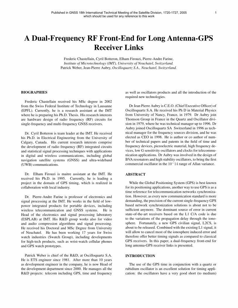
A Dual-Frequency RF Front-End for Long Antenna-GPSReceiver Links
Frederic Chastellain, Cyril Botteron, Elham Firouzi, Pierre-Andre Farine,Institute of Microtechnology (IMT), University of Neuchatel, Switzerland.
Patrick Weber, Jean-Pierre Aubry, Oscilloquartz S.A., Neuchatel, Switzerland.
Published in GNSS 18th International Technical Meeting of the Satellite Division, 1720-1727, 2005which should be used for any reference to this work
1
BIOGRAPHIES
Frederic Chastellain received his MSc degree in 2002from the Swiss Federal Institute of Technology in Lausanne(EPFL). Currently, he is a research assistant at the IMTwhere he is preparing his Ph.D. Thesis. His research interestsare hardware design of radio frequency (RF) circuits forsingle-frequency and multi-frequency GNSS receivers.
Dr. Cyril Botteron is team leader at the IMT. He receivedhis Ph.D. in Electrical Engineering from the University ofCalgary, Canada. His current research interests comprisethe development of radio frequency (RF) integrated circuitsand statistical signal processing techniques with applicationsin digital and wireless communications, including globalnavigation satellite systems (GNSS) and ultra-wideband(UWB) communications.
Dr. Elham Firouzi is maitre assistant at the IMT. Hereceived his Ph.D. in 1995. Currently, he is leading aproject in the domain of GPS timing, which is realized incollaboration with local industry.
Dr. Pierre-Andre Farine is professor of electronics andsignal processing at the IMT. He works in the field of low-power integrated products for portable devices, includingwireless telecommunication and GNSS systems. He isHead of the electronics and signal processing laboratory(ESPLAB) at IMT. His R&D group works also for videoand audio compression algorithms and signal processing.He received his Doctoral and MSc Degree from Universityof Neuchatel. He has been working 17 years for Swisswatch industries (Swatch Group), including developmentsfor high-tech products, such as wrist-watch cellular phonesand GPS watch prototypes.
Patrick Weber is chief of the R&D, at Oscilloquartz S.A.He is ETS engineer since 1981. After more than 10 yearsas development engineer in the company, he is now Head ofthe development department since 2000. He manages all theR&D projects: telecom including GPS, time and frequency
as well as oscillators products and all the introduction of therequired new technologies.
Dr Jean Pierre Aubry is C.E.O. (Chief Executive Officer) ofOscilloquartz S.A. He received his Ph D in Material Physicsfrom University of Nancy, France, in 1979. Dr Aubry joinThomson Group in France in the Quartz and Oscillator divi-sion in 1979, where he was technical manager up to 1996. DrAubry joined Oscilloquartz SA Switzerland in 1996 as tech-nical manager for the frequency sources division, and he waselected as CEO in 1998. He is author or co author of num-ber of technical papers and patents in the field of time andfrequency devices, piezoelectric material, high frequency de-vices, low G sensitivity oscillators and clocks for telecommu-nication applications. Dr Aubry was involved in the design ofBVA resonators and high stability oscillators, to bring the firstcommercial oscillator in the 10−14 range of Allan variance.
ABSTRACT
While the Global Positioning System (GPS) is best knownfor its positioning applications, another way to use GPS is as atime reference for telecommunication networks synchroniza-tion. However, as every new communication standard is moredemanding, the precision of the current single-frequency GPSbased network synchronization solutions is about not to besufficient anymore. The dominant source of error in currentstate-of-the-art receivers based on the L1 C/A code is dueto the variations of the propagation delay through the iono-sphere. Fortunately, a new GPS civilian signal, L2CS, isabout to be released. Combined with the existing L1 signal, itwill allow to cancel most of the ionosphere induced error andtherefore offer better timing signals as compared to classicalGPS receivers. In this paper, a dual-frequency front-end forlong antenna-GPS receiver links is presented.
INTRODUCTION
The use of the GPS time in conjunction with a quartz orrubidium oscillator is an excellent solution for timing appli-cation: the oscillators have a very good short (to medium)
term stability and accuracy but their performance degrade atlong term. Fortunately, the time reference provided by theGPS complements the oscillators performance quite well: itis accurate at long term but the pseudorandom noise codes(PRN) used to spread the message data makes it unusable atshort term. As a consequence, the long term stability of theGPS time, when combined with the short term stability ofoscillators, relaxes the requirements of the oscillator as com-pared to other free-running oscillators such as cesium or hy-drogen maser. The consequence is a much lower cost, areaand weight at a high level of performances when used witha stable and accurate oscillator, such as an OCXO [1]. Suchsystems are called GPS disciplined oscillators (GPSDO).
With the apparition of several new civilian signals in theyears to come, there’s no doubt that the next ”big thing” inGlobal Navigation Satellite Systems (GNSS) is the use ofmultiple frequencies to improve the performances of the nextgeneration of receivers. For timing applications, this is alsoa great opportunity. The main factor limiting the precisionof today’s GPSDO is the delay introduced by the ionosphere.Though, when two signals with different carriers are avail-able, the ionospheric error can be corrected. The ionosphere-free pseudorange measurement ρ∗ is given in [2] as :
ρ∗ =f2
L1
(f2L2 − f2
L2)ρL1 −
f2L2
(f2L2 − f2
L2)ρL2 (1)
where ρL1 and ρL2 are the pseudorange measurements atthe L1 and L2 frequency, respectively.
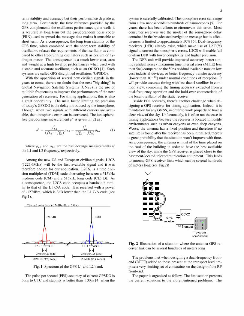
Among the new US and European civilian signals, L2CS(1227.6MHz) will be the first available signal and it wastherefore chosen for our application. L2CS, is a time divi-sion multiplexed (TDM) code alternating between a 515kHzmedium code (CM) and a 515kHz long code (CL) [3]. Asa consequence, the L2CS code occupies a bandwidth simi-lar to that of the L1 C/A code. It is received with a powerof -127dBm, which is 3dB lower than the L1 C/A code (seeFig.1).
Fig. 1 Spectrum of the GPS L1 and L2 band.
The pulse per second (PPS) accuracy of current GPSDO is50ns to UTC and stability is better than 100ns [4] when the
system is carefully calibrated. The ionosphere error can rangefrom a few nanoseconds to hundreds of nanoseconds [5]. Foryears, there has been efforts to circumvent this error. Mostconsumer receivers use the model of the ionosphere delaycontained in the broadcasted navigation message but its effec-tiveness is limited to approximately 50% [6]. Dual-frequencyreceivers (DFR) already exist, which make use of L2 P(Y)signal to correct the ionospheric errors. L2CS will enable fullcivilian DFR with lower complexity and higher precision.
The DFR unit will provide improved accuracy, better tim-ing residual noise ( maximum time interval error (MTIE) lessthan 5ns) compared to the 50ns residual available now on lowcost industrial devices, or better frequency transfer accuracy(lower than 10−13) under normal conditions of reception. Itwill provide accurate timing with less than 4 satellites in com-mon view, combining the timing accuracy extracted from adual-frequency operation and the hold-over characteristic ofthe local oscillator of the static receiver.
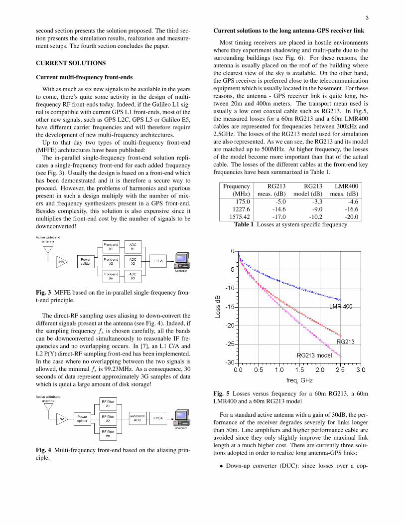
Beside PPS accuracy, there’s another challenge when de-signing a GPS receiver for timing application. Indeed, it ismandatory for any GNSS, in order to work properly, to have aclear view of the sky. Unfortunately, it is often not the case intiming applications because the receiver is located in hostileenvironments such as urban canyons or even deep canyons.Worse, the antenna has a fixed position and therefore if nosatellite is found after the receiver has been initialized, there’sa great probability that the situation won’t improve with time.As a consequence, the antenna is most of the time placed onthe roof of the building in order to have the best availableview of the sky, while the GPS receiver is placed close to thebasement-located telecommunication equipment. This leadsto antenna-GPS receiver links which can be several hundredsof meters long (see Fig.2)!
Fig. 2 Illustration of a situation where the antenna-GPS re-ceiver link can be several hundreds of meters long
The problems met when designing a dual-frequency front-end (DFFE) added to those present at the transport level im-pose a very limiting set of constraints on the design of the RFfront-end.
The paper is organized as follow. The first section presentsthe current solutions to the aforementioned problems. The
2
second section presents the solution proposed. The third sec-tion presents the simulation results, realization and measure-ment setups. The fourth section concludes the paper.
CURRENT SOLUTIONS
Current multi-frequency front-ends
With as much as six new signals to be available in the yearsto come, there’s quite some activity in the design of multi-frequency RF front-ends today. Indeed, if the Galileo L1 sig-nal is compatible with current GPS L1 front-ends, most of theother new signals, such as GPS L2C, GPS L5 or Galileo E5,have different carrier frequencies and will therefore requirethe development of new multi-frequency architectures.
Up to that day two types of multi-frequency front-end(MFFE) architectures have been published:
The in-parallel single-frequency front-end solution repli-cates a single-frequency front-end for each added frequency(see Fig. 3). Usually the design is based on a front-end whichhas been demonstrated and it is therefore a secure way toproceed. However, the problems of harmonics and spuriouspresent in such a design multiply with the number of mix-ers and frequency synthesizers present in a GPS front-end.Besides complexity, this solution is also expensive since itmultiplies the front-end cost by the number of signals to bedownconverted!
Fig. 3 MFFE based on the in-parallel single-frequency fron-t-end principle.
The direct-RF sampling uses aliasing to down-convert thedifferent signals present at the antenna (see Fig. 4). Indeed, ifthe sampling frequency fs is chosen carefully, all the bandscan be downconverted simultaneously to reasonable IF fre-quencies and no overlapping occurs. In [7], an L1 C/A andL2 P(Y) direct-RF sampling front-end has been implemented.In the case where no overlapping between the two signals isallowed, the minimal fs is 99.23MHz. As a consequence, 30seconds of data represent approximately 3G samples of datawhich is quiet a large amount of disk storage!
Fig. 4 Multi-frequency front-end based on the aliasing prin-ciple.
Current solutions to the long antenna-GPS receiver link
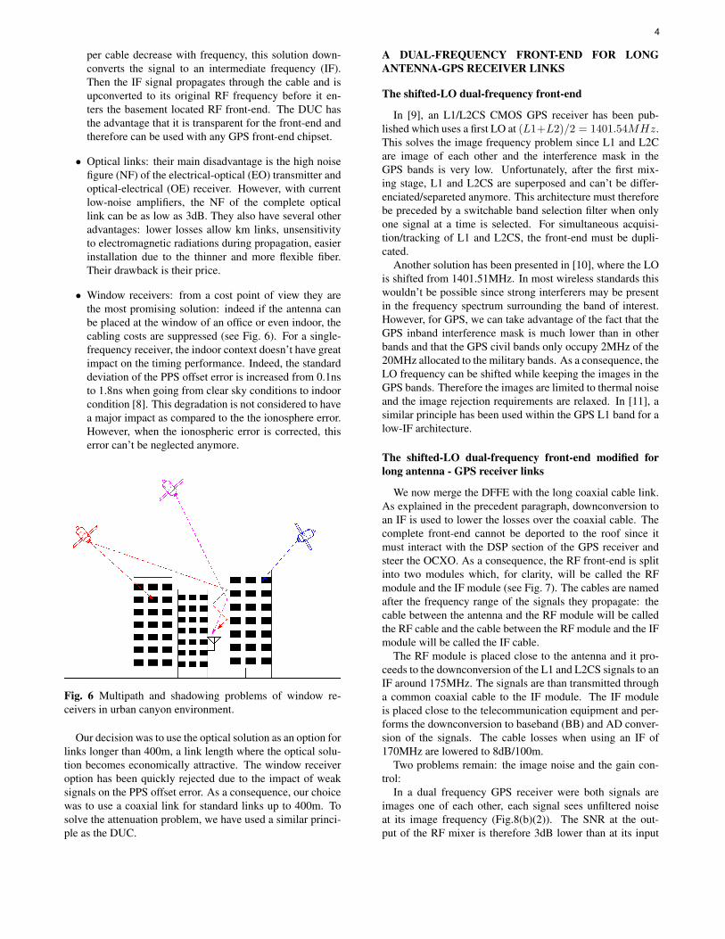
Most timing receivers are placed in hostile environmentswhere they experiment shadowing and multi-paths due to thesurrounding buildings (see Fig. 6). For these reasons, theantenna is usually placed on the roof of the building wherethe clearest view of the sky is available. On the other hand,the GPS receiver is preferred close to the telecommunicationequipment which is usually located in the basement. For thesereasons, the antenna - GPS receiver link is quite long, be-tween 20m and 400m meters. The transport mean used isusually a low cost coaxial cable such as RG213. In Fig.5,the measured losses for a 60m RG213 and a 60m LMR400cables are represented for frequencies between 300kHz and2.5GHz. The losses of the RG213 model used for simulationare also represented. As we can see, the RG213 and its modelare matched up to 500MHz. At higher frequency, the lossesof the model become more important than that of the actualcable. The losses of the different cables at the front-end keyfrequencies have been summarized in Table 1.
Frequency RG213 RG213 LMR400(MHz) meas. (dB) model (dB) meas. (dB)175.0 -5.0 -3.3 -4.6
1227.6 -14.6 -9.0 -16.61575.42 -17.0 -10.2 -20.0
Table 1 Losses at system specific frequency
Fig. 5 Losses versus frequency for a 60m RG213, a 60mLMR400 and a 60m RG213 model
For a standard active antenna with a gain of 30dB, the per-formance of the receiver degrades severely for links longerthan 50m. Line amplifiers and higher performance cable areavoided since they only slightly improve the maximal linklength at a much higher cost. There are currently three solu-tions adopted in order to realize long antenna-GPS links:
• Down-up converter (DUC): since losses over a cop-
3
per cable decrease with frequency, this solution down-converts the signal to an intermediate frequency (IF).Then the IF signal propagates through the cable and isupconverted to its original RF frequency before it en-ters the basement located RF front-end. The DUC hasthe advantage that it is transparent for the front-end andtherefore can be used with any GPS front-end chipset.
• Optical links: their main disadvantage is the high noisefigure (NF) of the electrical-optical (EO) transmitter andoptical-electrical (OE) receiver. However, with currentlow-noise amplifiers, the NF of the complete opticallink can be as low as 3dB. They also have several otheradvantages: lower losses allow km links, unsensitivityto electromagnetic radiations during propagation, easierinstallation due to the thinner and more flexible fiber.Their drawback is their price.
• Window receivers: from a cost point of view they arethe most promising solution: indeed if the antenna canbe placed at the window of an office or even indoor, thecabling costs are suppressed (see Fig. 6). For a single-frequency receiver, the indoor context doesn’t have greatimpact on the timing performance. Indeed, the standarddeviation of the PPS offset error is increased from 0.1nsto 1.8ns when going from clear sky conditions to indoorcondition [8]. This degradation is not considered to havea major impact as compared to the the ionosphere error.However, when the ionospheric error is corrected, thiserror can’t be neglected anymore.
Fig. 6 Multipath and shadowing problems of window re-ceivers in urban canyon environment.
Our decision was to use the optical solution as an option forlinks longer than 400m, a link length where the optical solu-tion becomes economically attractive. The window receiveroption has been quickly rejected due to the impact of weaksignals on the PPS offset error. As a consequence, our choicewas to use a coaxial link for standard links up to 400m. Tosolve the attenuation problem, we have used a similar princi-ple as the DUC.
A DUAL-FREQUENCY FRONT-END FOR LONGANTENNA-GPS RECEIVER LINKS
The shifted-LO dual-frequency front-end
In [9], an L1/L2CS CMOS GPS receiver has been pub-lished which uses a first LO at (L1+L2)/2 = 1401.54MHz.This solves the image frequency problem since L1 and L2Care image of each other and the interference mask in theGPS bands is very low. Unfortunately, after the first mix-ing stage, L1 and L2CS are superposed and can’t be differ-enciated/separeted anymore. This architecture must thereforebe preceded by a switchable band selection filter when onlyone signal at a time is selected. For simultaneous acquisi-tion/tracking of L1 and L2CS, the front-end must be dupli-cated.
Another solution has been presented in [10], where the LOis shifted from 1401.51MHz. In most wireless standards thiswouldn’t be possible since strong interferers may be presentin the frequency spectrum surrounding the band of interest.However, for GPS, we can take advantage of the fact that theGPS inband interference mask is much lower than in otherbands and that the GPS civil bands only occupy 2MHz of the20MHz allocated to the military bands. As a consequence, theLO frequency can be shifted while keeping the images in theGPS bands. Therefore the images are limited to thermal noiseand the image rejection requirements are relaxed. In [11], asimilar principle has been used within the GPS L1 band for alow-IF architecture.
The shifted-LO dual-frequency front-end modified forlong antenna - GPS receiver links
We now merge the DFFE with the long coaxial cable link.As explained in the precedent paragraph, downconversion toan IF is used to lower the losses over the coaxial cable. Thecomplete front-end cannot be deported to the roof since itmust interact with the DSP section of the GPS receiver andsteer the OCXO. As a consequence, the RF front-end is splitinto two modules which, for clarity, will be called the RFmodule and the IF module (see Fig. 7). The cables are namedafter the frequency range of the signals they propagate: thecable between the antenna and the RF module will be calledthe RF cable and the cable between the RF module and the IFmodule will be called the IF cable.
The RF module is placed close to the antenna and it pro-ceeds to the downconversion of the L1 and L2CS signals to anIF around 175MHz. The signals are than transmitted througha common coaxial cable to the IF module. The IF moduleis placed close to the telecommunication equipment and per-forms the downconversion to baseband (BB) and AD conver-sion of the signals. The cable losses when using an IF of170MHz are lowered to 8dB/100m.
Two problems remain: the image noise and the gain con-trol:
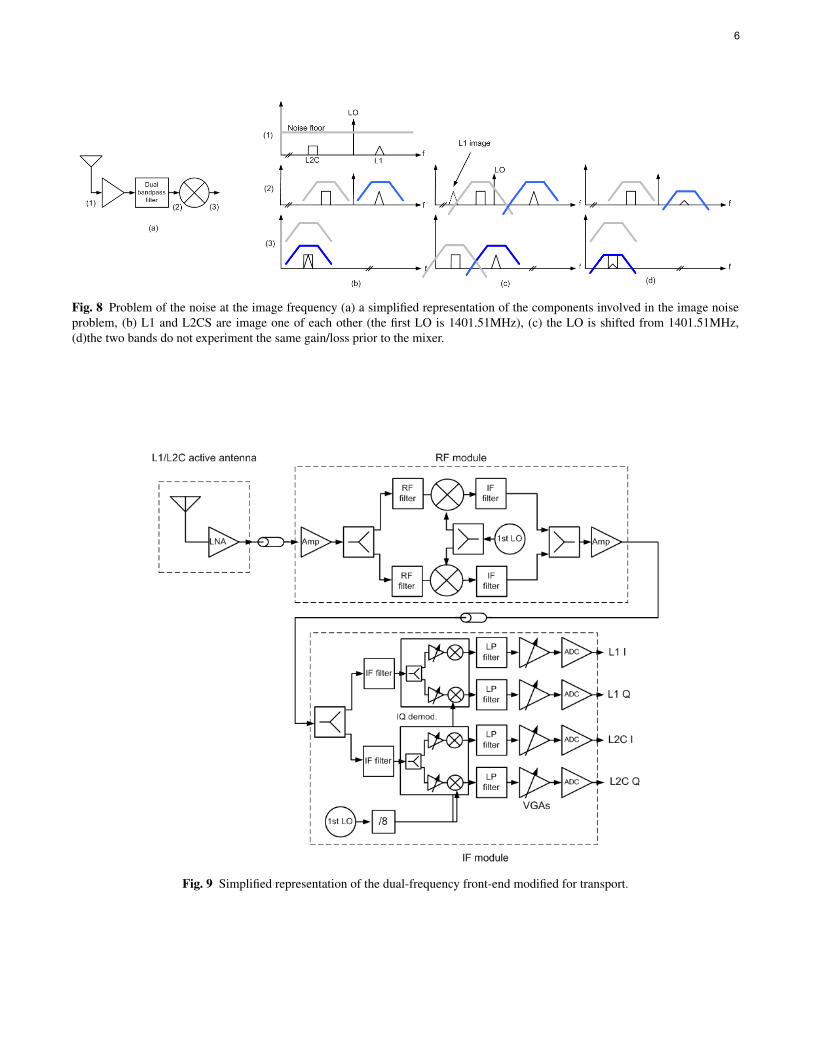
In a dual frequency GPS receiver were both signals areimages one of each other, each signal sees unfiltered noiseat its image frequency (Fig.8(b)(2)). The SNR at the out-put of the RF mixer is therefore 3dB lower than at its input
4
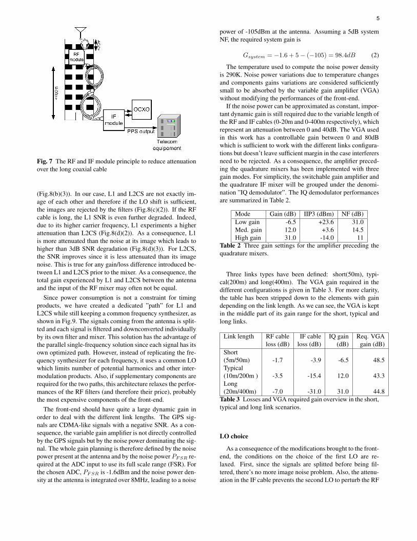
Fig. 7 The RF and IF module principle to reduce attenuationover the long coaxial cable
(Fig.8(b)(3)). In our case, L1 and L2CS are not exactly im-age of each other and therefore if the LO shift is sufficient,the images are rejected by the filters (Fig.8(c)(2)). If the RFcable is long, the L1 SNR is even further degraded. Indeed,due to its higher carrier frequency, L1 experiments a higherattenuation than L2CS (Fig.8(d)(2)). As a consequence, L1is more attenuated than the noise at its image which leads tohigher than 3dB SNR degradation (Fig.8(d)(3)). For L2CS,the SNR improves since it is less attenuated than its imagenoise. This is true for any gain/loss difference introduced be-tween L1 and L2CS prior to the mixer. As a consequence, thetotal gain experienced by L1 and L2CS between the antennaand the input of the RF mixer may often not be equal.
Since power consumption is not a constraint for timingproducts, we have created a dedicated ”path” for L1 andL2CS while still keeping a common frequency synthesizer, asshown in Fig.9. The signals coming from the antenna is split-ted and each signal is filtered and downconverted individuallyby its own filter and mixer. This solution has the advantage ofthe parallel single-frequency solution since each signal has itsown optimized path. However, instead of replicating the fre-quency synthesizer for each frequency, it uses a common LOwhich limits number of potential harmonics and other inter-modulation products. Also, if supplementary components arerequired for the two paths, this architecture relaxes the perfor-mances of the RF filters (and therefore their price), probablythe most expensive components of the front-end.
The front-end should have quite a large dynamic gain inorder to deal with the different link lengths. The GPS sig-nals are CDMA-like signals with a negative SNR. As a con-sequence, the variable gain amplifier is not directly controlledby the GPS signals but by the noise power dominating the sig-nal. The whole gain planning is therefore defined by the noisepower present at the antenna and by the noise power PFSR re-quired at the ADC input to use its full scale range (FSR). Forthe chosen ADC, PFSR is -1.6dBm and the noise power den-sity at the antenna is integrated over 8MHz, leading to a noise
power of -105dBm at the antenna. Assuming a 5dB systemNF, the required system gain is
Gsystem = −1.6 + 5− (−105) = 98.4dB (2)
The temperature used to compute the noise power densityis 290K. Noise power variations due to temperature changesand components gains variations are considered sufficientlysmall to be absorbed by the variable gain amplifier (VGA)without modifying the performances of the front-end.
If the noise power can be approximated as constant, impor-tant dynamic gain is still required due to the variable length ofthe RF and IF cables (0-20m and 0-400m respectively), whichrepresent an attenuation between 0 and 40dB. The VGA usedin this work has a controllable gain between 0 and 80dBwhich is sufficient to work with the different links configura-tions but doesn’t leave sufficient margin in the case interferersneed to be rejected. As a consequence, the amplifier preced-ing the quadrature mixers has been implemented with threegain modes. For simplicity, the switchable gain amplifier andthe quadrature IF mixer will be grouped under the denomi-nation ”IQ demodulator”. The IQ demodulator performancesare summarized in Table 2.
Mode Gain (dB) IIP3 (dBm) NF (dB)Low gain -6.5 +23.6 31.0Med. gain 12.0 +3.6 14.5High gain 31.0 -14.0 11
Table 2 Three gain settings for the amplifier preceding thequadrature mixers.
Three links types have been defined: short(50m), typi-cal(200m) and long(400m). The VGA gain required in thedifferent configurations is given in Table 3. For more clarity,the table has been stripped down to the elements with gaindepending on the link length. As we can see, the VGA is keptin the middle part of its gain range for the short, typical andlong links.
Link length RF cable IF cable IQ gain Req. VGAloss (dB) loss (dB) (dB) gain (dB)
Short(5m/50m) -1.7 -3.9 -6.5 48.5Typical(10m/200m ) -3.5 -15.4 12.0 43.3Long(20m/400m) -7.0 -31.0 31.0 44.8
Table 3 Losses and VGA required gain overview in the short,typical and long link scenarios.
LO choice
As a consequence of the modifications brought to the front-end, the conditions on the choice of the first LO are re-laxed. First, since the signals are splitted before being fil-tered, there’s no more image noise problem. Also, the attenu-ation in the IF cable prevents the second LO to perturb the RF
5
6
Fig. 8 Problem of the noise at the image frequency (a) a simplified representation of the components involved in the image noiseproblem, (b) L1 and L2CS are image one of each other (the first LO is 1401.51MHz), (c) the LO is shifted from 1401.51MHz,(d)the two bands do not experiment the same gain/loss prior to the mixer.
Fig. 9 Simplified representation of the dual-frequency front-end modified for transport.
module. With a first LO of 1405.5MHz, the L1 and L2CS IFare 169.92MHz and 177.9MHz respectively. The 2nd LO is175.6875MHz resulting in L1 and L2CS baseband frequen-cies at 2.2125MHz and 5.7675MHz respectively.
SIMULATION RESULTS, REALIZATION AND MEA-SUREMENT SETUP
Simulation results
The front-end has been simulated with Agilent’s AdvancedDesign System (ADS). Most models used for simulation areADS system models. Several simulation engines such as theHarmonic Balance (HB), Envelope or S-parameter have beenused to check the performances of the front-end in its differ-ent configurations. Simulation is very convenient for this typeof system since it allows to perform various sweeps such asthat of the RF and IF cables lengths.
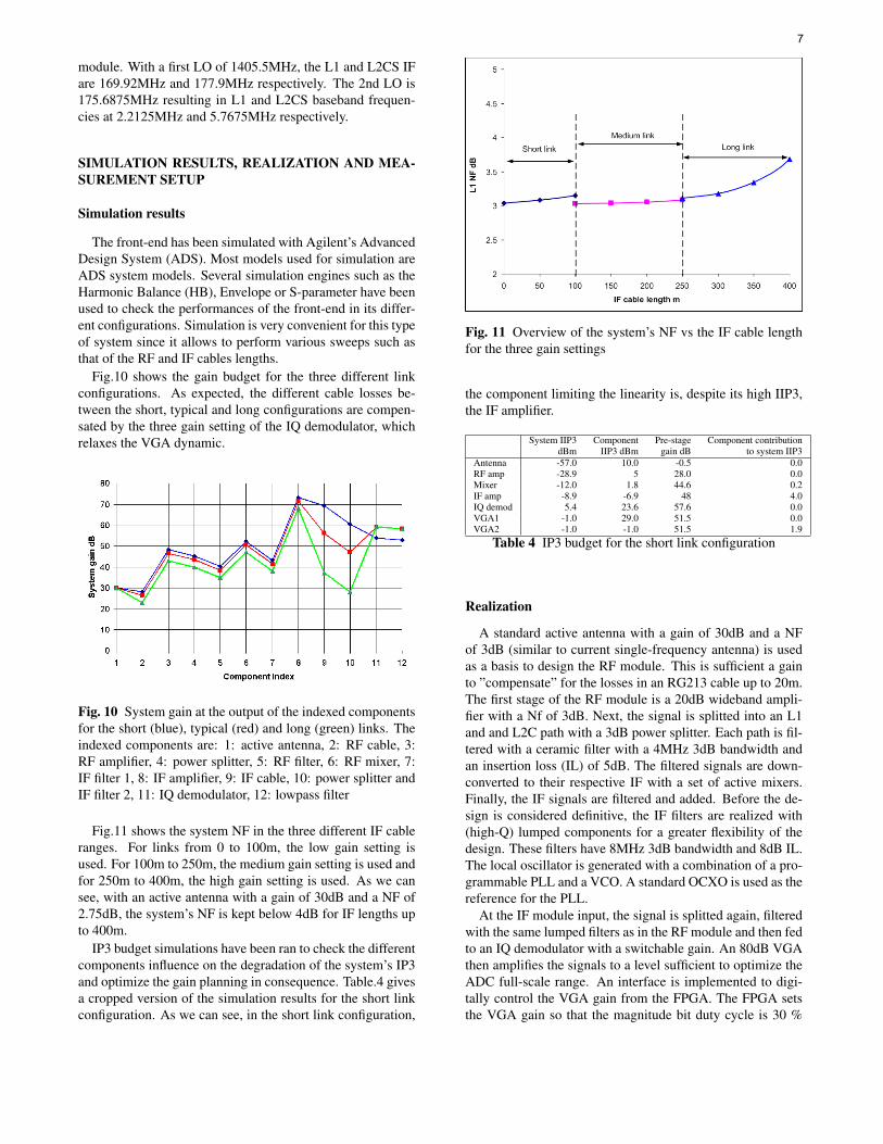
Fig.10 shows the gain budget for the three different linkconfigurations. As expected, the different cable losses be-tween the short, typical and long configurations are compen-sated by the three gain setting of the IQ demodulator, whichrelaxes the VGA dynamic.
Fig. 10 System gain at the output of the indexed componentsfor the short (blue), typical (red) and long (green) links. Theindexed components are: 1: active antenna, 2: RF cable, 3:RF amplifier, 4: power splitter, 5: RF filter, 6: RF mixer, 7:IF filter 1, 8: IF amplifier, 9: IF cable, 10: power splitter andIF filter 2, 11: IQ demodulator, 12: lowpass filter
Fig.11 shows the system NF in the three different IF cableranges. For links from 0 to 100m, the low gain setting isused. For 100m to 250m, the medium gain setting is used andfor 250m to 400m, the high gain setting is used. As we cansee, with an active antenna with a gain of 30dB and a NF of2.75dB, the system’s NF is kept below 4dB for IF lengths upto 400m.
IP3 budget simulations have been ran to check the differentcomponents influence on the degradation of the system’s IP3and optimize the gain planning in consequence. Table.4 givesa cropped version of the simulation results for the short linkconfiguration. As we can see, in the short link configuration,
Fig. 11 Overview of the system’s NF vs the IF cable lengthfor the three gain settings
the component limiting the linearity is, despite its high IIP3,the IF amplifier.
System IIP3 Component Pre-stage Component contributiondBm IIP3 dBm gain dB to system IIP3
Antenna -57.0 10.0 -0.5 0.0RF amp -28.9 5 28.0 0.0Mixer -12.0 1.8 44.6 0.2IF amp -8.9 -6.9 48 4.0IQ demod 5.4 23.6 57.6 0.0VGA1 -1.0 29.0 51.5 0.0VGA2 -1.0 -1.0 51.5 1.9
Table 4 IP3 budget for the short link configuration
Realization
A standard active antenna with a gain of 30dB and a NFof 3dB (similar to current single-frequency antenna) is usedas a basis to design the RF module. This is sufficient a gainto ”compensate” for the losses in an RG213 cable up to 20m.The first stage of the RF module is a 20dB wideband ampli-fier with a Nf of 3dB. Next, the signal is splitted into an L1and and L2C path with a 3dB power splitter. Each path is fil-tered with a ceramic filter with a 4MHz 3dB bandwidth andan insertion loss (IL) of 5dB. The filtered signals are down-converted to their respective IF with a set of active mixers.Finally, the IF signals are filtered and added. Before the de-sign is considered definitive, the IF filters are realized with(high-Q) lumped components for a greater flexibility of thedesign. These filters have 8MHz 3dB bandwidth and 8dB IL.The local oscillator is generated with a combination of a pro-grammable PLL and a VCO. A standard OCXO is used as thereference for the PLL.
At the IF module input, the signal is splitted again, filteredwith the same lumped filters as in the RF module and then fedto an IQ demodulator with a switchable gain. An 80dB VGAthen amplifies the signals to a level sufficient to optimize theADC full-scale range. An interface is implemented to digi-tally control the VGA gain from the FPGA. The FPGA setsthe VGA gain so that the magnitude bit duty cycle is 30 %
7
and the sign bit duty cycle is 50 %. The LO of the IF moduleis locked to the steered OCXO. The ADCs provide 6 bits foreach of L1/L2C I and Q path. The bits are fed to an FPGAwhich determines the magnitude and sign bits of each signalfrom the bits provided by the front-end. The sampling clockis derived from a divided by N version of the LO fed by theFPGA.
To reduce installation costs, the DC supply of the RF mod-ule and of the antenna must be supplied via the coaxial cable.The IF module supplies +8V via the IF cable. In the RF mod-ule, a +6V and a +5V power regulator are used to supply theamplifiers and mixers respectively. A third +5V power regu-lator is used to supply the active antenna.
Measurement setup
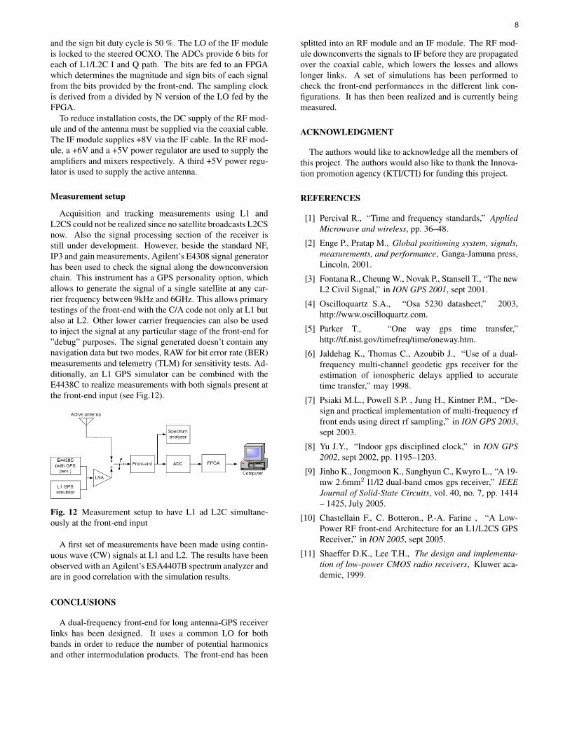
Acquisition and tracking measurements using L1 andL2CS could not be realized since no satellite broadcasts L2CSnow. Also the signal processing section of the receiver isstill under development. However, beside the standard NF,IP3 and gain measurements, Agilent’s E4308 signal generatorhas been used to check the signal along the downconversionchain. This instrument has a GPS personality option, whichallows to generate the signal of a single satellite at any car-rier frequency between 9kHz and 6GHz. This allows primarytestings of the front-end with the C/A code not only at L1 butalso at L2. Other lower carrier frequencies can also be usedto inject the signal at any particular stage of the front-end for”debug” purposes. The signal generated doesn’t contain anynavigation data but two modes, RAW for bit error rate (BER)measurements and telemetry (TLM) for sensitivity tests. Ad-ditionally, an L1 GPS simulator can be combined with theE4438C to realize measurements with both signals present atthe front-end input (see Fig.12).
Fig. 12 Measurement setup to have L1 ad L2C simultane-ously at the front-end input
A first set of measurements have been made using contin-uous wave (CW) signals at L1 and L2. The results have beenobserved with an Agilent’s ESA4407B spectrum analyzer andare in good correlation with the simulation results.
CONCLUSIONS
A dual-frequency front-end for long antenna-GPS receiverlinks has been designed. It uses a common LO for bothbands in order to reduce the number of potential harmonicsand other intermodulation products. The front-end has been
splitted into an RF module and an IF module. The RF mod-ule downconverts the signals to IF before they are propagatedover the coaxial cable, which lowers the losses and allowslonger links. A set of simulations has been performed tocheck the front-end performances in the different link con-figurations. It has then been realized and is currently beingmeasured.
ACKNOWLEDGMENT
The authors would like to acknowledge all the members ofthis project. The authors would also like to thank the Innova-tion promotion agency (KTI/CTI) for funding this project.
REFERENCES
[1] Percival R., “Time and frequency standards,” AppliedMicrowave and wireless, pp. 36–48.
[2] Enge P., Pratap M., Global positioning system, signals,measurements, and performance, Ganga-Jamuna press,Lincoln, 2001.
[3] Fontana R., Cheung W., Novak P., Stansell T., “The newL2 Civil Signal,” in ION GPS 2001, sept 2001.
[4] Oscilloquartz S.A., “Osa 5230 datasheet,” 2003,http://www.oscilloquartz.com.
[5] Parker T., “One way gps time transfer,”http://tf.nist.gov/timefreq/time/oneway.htm.
[6] Jaldehag K., Thomas C., Azoubib J., “Use of a dual-frequency multi-channel geodetic gps receiver for theestimation of ionospheric delays applied to accuratetime transfer,” may 1998.
[7] Psiaki M.L., Powell S.P. , Jung H., Kintner P.M., “De-sign and practical implementation of multi-frequency rffront ends using direct rf sampling,” in ION GPS 2003,sept 2003.
[8] Yu J.Y., “Indoor gps disciplined clock,” in ION GPS2002, sept 2002, pp. 1195–1203.
[9] Jinho K., Jongmoon K., Sanghyun C., Kwyro L., “A 19-mw 2.6mm2 l1/l2 dual-band cmos gps receiver,” IEEEJournal of Solid-State Circuits, vol. 40, no. 7, pp. 1414– 1425, July 2005.
[10] Chastellain F., C. Botteron., P.-A. Farine , “A Low-Power RF front-end Architecture for an L1/L2CS GPSReceiver,” in ION 2005, sept 2005.
[11] Shaeffer D.K., Lee T.H., The design and implementa-tion of low-power CMOS radio receivers, Kluwer aca-demic, 1999.
8