Embed Size (px)
Citation preview
Computer-Aided Design & Applications, 6(1-4), 2009, xxx-yyy
1
Computer-Aided Design and Applications © 2009 CAD Solutions, LLC
http://www.cadanda.com
A Design Method for 3D Origami Based on Rotational Sweep
Jun Mitani
University of Tsukuba / JST, [email protected]
ABSTRACT
In this paper, a method for designing origami in which shape is based on the 3D geometry generated by the rotational sweep that is commonly used in CG and CAD systems is proposed. The target shape is designed by rotating a two-dimensional polyline around an axis by a unit of 360/N degrees (N > 2). To make a shape with a single sheet of paper, appropriate flaps are placed in between the constituent polygonal faces that constitute the elements of the target shape. The proposed method generates a crease pattern, i.e. a specification document consisting of mountain/valley fold lines, for folding the origami. Because the shape becomes smoother if we set the input polyline to be finer and N larger, this method can also produce approximate designs for three-dimensional curved origami. This paper describes two principal types of rotational shape origami construction; cylindrical and conical. The origami are folded from a rectangle and a regular N-gon sheet of paper, respectively. The proposed method was implemented on a PC and its validity was demonstrated by constructing several 3D origami.
Keywords: origami, crease pattern, rotational shape DOI: 10.3722/cadaps.2009.xxx-yyy
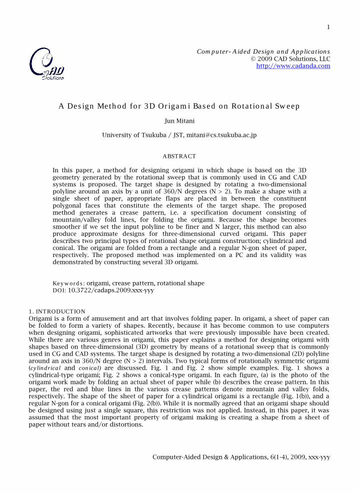
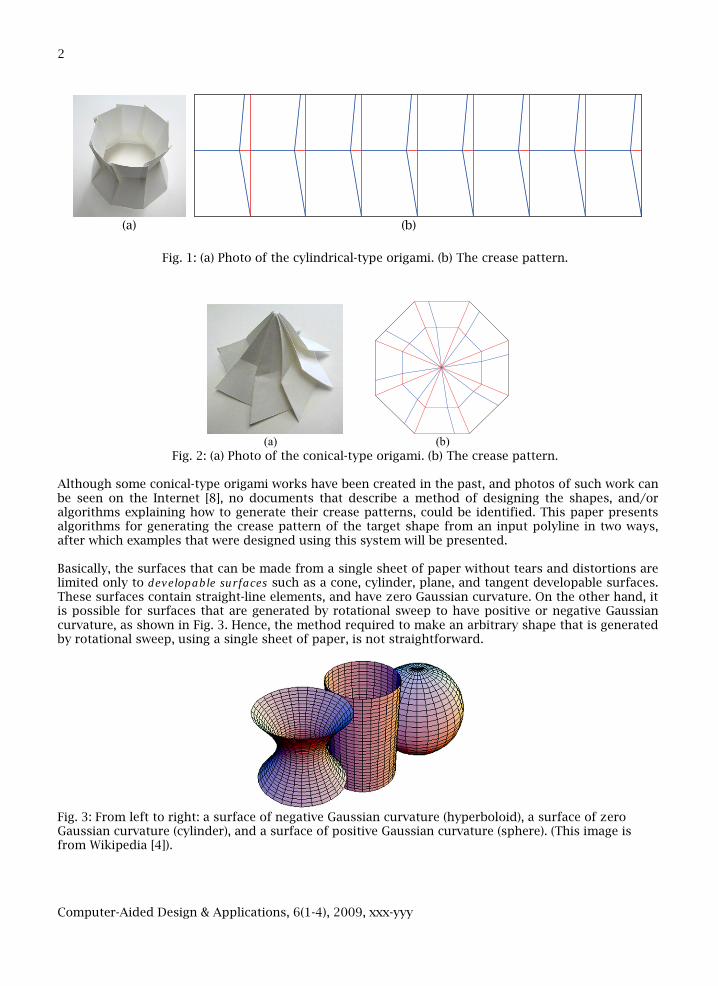
1. INTRODUCTION Origami is a form of amusement and art that involves folding paper. In origami, a sheet of paper can be folded to form a variety of shapes. Recently, because it has become common to use computers when designing origami, sophisticated artworks that were previously impossible have been created. While there are various genres in origami, this paper explains a method for designing origami with shapes based on three-dimensional (3D) geometry by means of a rotational sweep that is commonly used in CG and CAD systems. The target shape is designed by rotating a two-dimensional (2D) polyline around an axis in 360/N degree (N > 2) intervals. Two typical forms of rotationally symmetric origami (cylindrical and conical) are discussed. Fig. 1 and Fig. 2 show simple examples. Fig. 1 shows a cylindrical-type origami; Fig. 2 shows a conical-type origami. In each figure, (a) is the photo of the origami work made by folding an actual sheet of paper while (b) describes the crease pattern. In this paper, the red and blue lines in the various crease patterns denote mountain and valley folds, respectively. The shape of the sheet of paper for a cylindrical origami is a rectangle (Fig. 1(b)), and a regular N-gon for a conical origami (Fig. 2(b)). While it is normally agreed that an origami shape should be designed using just a single square, this restriction was not applied. Instead, in this paper, it was assumed that the most important property of origami making is creating a shape from a sheet of paper without tears and/or distortions.
Computer-Aided Design & Applications, 6(1-4), 2009, xxx-yyy
2
(a) (b)
Fig. 1: (a) Photo of the cylindrical-type origami. (b) The crease pattern.
(a) (b)
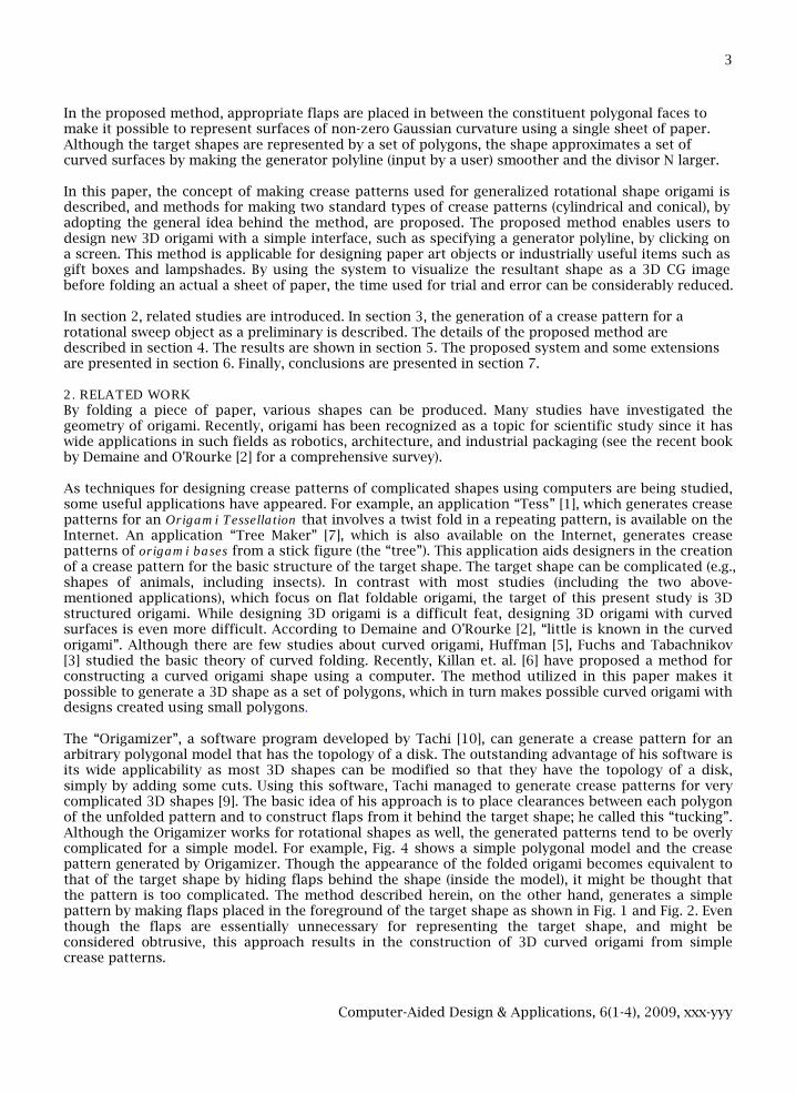
Fig. 2: (a) Photo of the conical-type origami. (b) The crease pattern. Although some conical-type origami works have been created in the past, and photos of such work can be seen on the Internet [8], no documents that describe a method of designing the shapes, and/or algorithms explaining how to generate their crease patterns, could be identified. This paper presents algorithms for generating the crease pattern of the target shape from an input polyline in two ways, after which examples that were designed using this system will be presented. Basically, the surfaces that can be made from a single sheet of paper without tears and distortions are limited only to developable surfaces such as a cone, cylinder, plane, and tangent developable surfaces. These surfaces contain straight-line elements, and have zero Gaussian curvature. On the other hand, it is possible for surfaces that are generated by rotational sweep to have positive or negative Gaussian curvature, as shown in Fig. 3. Hence, the method required to make an arbitrary shape that is generated by rotational sweep, using a single sheet of paper, is not straightforward.
Fig. 3: From left to right: a surface of negative Gaussian curvature (hyperboloid), a surface of zero Gaussian curvature (cylinder), and a surface of positive Gaussian curvature (sphere). (This image is from Wikipedia [4]).
Computer-Aided Design & Applications, 6(1-4), 2009, xxx-yyy
3
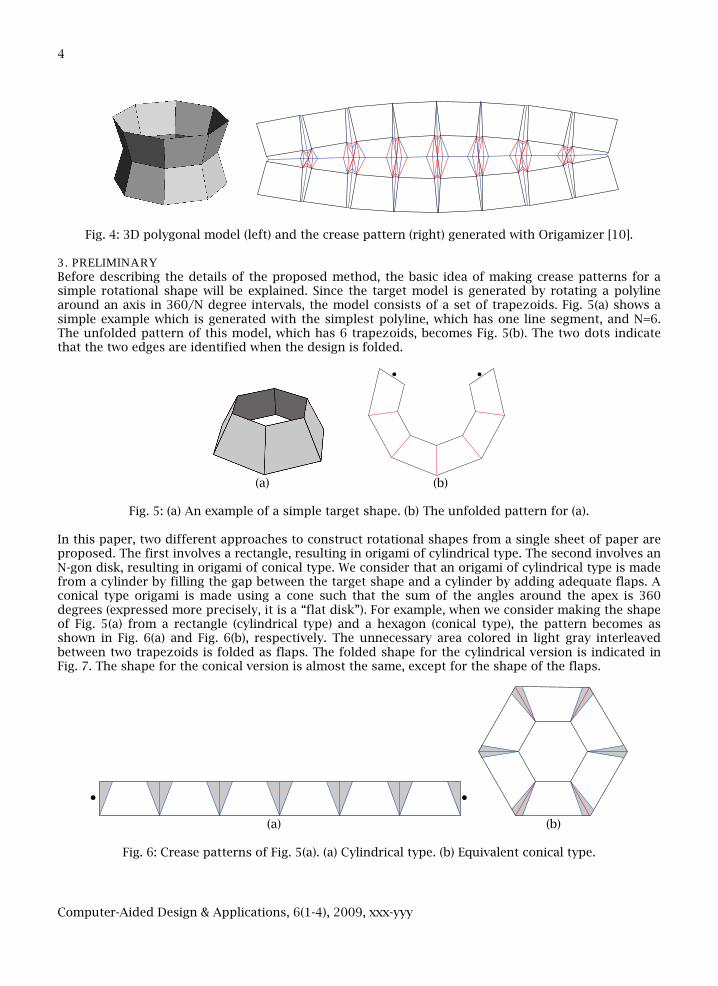
In the proposed method, appropriate flaps are placed in between the constituent polygonal faces to make it possible to represent surfaces of non-zero Gaussian curvature using a single sheet of paper. Although the target shapes are represented by a set of polygons, the shape approximates a set of curved surfaces by making the generator polyline (input by a user) smoother and the divisor N larger. In this paper, the concept of making crease patterns used for generalized rotational shape origami is described, and methods for making two standard types of crease patterns (cylindrical and conical), by adopting the general idea behind the method, are proposed. The proposed method enables users to design new 3D origami with a simple interface, such as specifying a generator polyline, by clicking on a screen. This method is applicable for designing paper art objects or industrially useful items such as gift boxes and lampshades. By using the system to visualize the resultant shape as a 3D CG image before folding an actual a sheet of paper, the time used for trial and error can be considerably reduced. In section 2, related studies are introduced. In section 3, the generation of a crease pattern for a rotational sweep object as a preliminary is described. The details of the proposed method are described in section 4. The results are shown in section 5. The proposed system and some extensions are presented in section 6. Finally, conclusions are presented in section 7. 2. RELATED WORK By folding a piece of paper, various shapes can be produced. Many studies have investigated the geometry of origami. Recently, origami has been recognized as a topic for scientific study since it has wide applications in such fields as robotics, architecture, and industrial packaging (see the recent book by Demaine and O'Rourke [2] for a comprehensive survey). As techniques for designing crease patterns of complicated shapes using computers are being studied, some useful applications have appeared. For example, an application “Tess” [1], which generates crease patterns for an Origami Tessellation that involves a twist fold in a repeating pattern, is available on the Internet. An application “Tree Maker” [7], which is also available on the Internet, generates crease patterns of origami bases from a stick figure (the “tree”). This application aids designers in the creation of a crease pattern for the basic structure of the target shape. The target shape can be complicated (e.g., shapes of animals, including insects). In contrast with most studies (including the two above-mentioned applications), which focus on flat foldable origami, the target of this present study is 3D structured origami. While designing 3D origami is a difficult feat, designing 3D origami with curved surfaces is even more difficult. According to Demaine and O'Rourke [2], “little is known in the curved origami”. Although there are few studies about curved origami, Huffman [5], Fuchs and Tabachnikov [3] studied the basic theory of curved folding. Recently, Killan et. al. [6] have proposed a method for constructing a curved origami shape using a computer. The method utilized in this paper makes it possible to generate a 3D shape as a set of polygons, which in turn makes possible curved origami with designs created using small polygons. The “Origamizer”, a software program developed by Tachi [10], can generate a crease pattern for an arbitrary polygonal model that has the topology of a disk. The outstanding advantage of his software is its wide applicability as most 3D shapes can be modified so that they have the topology of a disk, simply by adding some cuts. Using this software, Tachi managed to generate crease patterns for very complicated 3D shapes [9]. The basic idea of his approach is to place clearances between each polygon of the unfolded pattern and to construct flaps from it behind the target shape; he called this “tucking”. Although the Origamizer works for rotational shapes as well, the generated patterns tend to be overly complicated for a simple model. For example, Fig. 4 shows a simple polygonal model and the crease pattern generated by Origamizer. Though the appearance of the folded origami becomes equivalent to that of the target shape by hiding flaps behind the shape (inside the model), it might be thought that the pattern is too complicated. The method described herein, on the other hand, generates a simple pattern by making flaps placed in the foreground of the target shape as shown in Fig. 1 and Fig. 2. Even though the flaps are essentially unnecessary for representing the target shape, and might be considered obtrusive, this approach results in the construction of 3D curved origami from simple crease patterns.
Computer-Aided Design & Applications, 6(1-4), 2009, xxx-yyy
4
Fig. 4: 3D polygonal model (left) and the crease pattern (right) generated with Origamizer [10].
3. PRELIMINARY Before describing the details of the proposed method, the basic idea of making crease patterns for a simple rotational shape will be explained. Since the target model is generated by rotating a polyline around an axis in 360/N degree intervals, the model consists of a set of trapezoids. Fig. 5(a) shows a simple example which is generated with the simplest polyline, which has one line segment, and N=6. The unfolded pattern of this model, which has 6 trapezoids, becomes Fig. 5(b). The two dots indicate that the two edges are identified when the design is folded.
(a) (b)
Fig. 5: (a) An example of a simple target shape. (b) The unfolded pattern for (a).
In this paper, two different approaches to construct rotational shapes from a single sheet of paper are proposed. The first involves a rectangle, resulting in origami of cylindrical type. The second involves an N-gon disk, resulting in origami of conical type. We consider that an origami of cylindrical type is made from a cylinder by filling the gap between the target shape and a cylinder by adding adequate flaps. A conical type origami is made using a cone such that the sum of the angles around the apex is 360 degrees (expressed more precisely, it is a “flat disk”). For example, when we consider making the shape of Fig. 5(a) from a rectangle (cylindrical type) and a hexagon (conical type), the pattern becomes as shown in Fig. 6(a) and Fig. 6(b), respectively. The unnecessary area colored in light gray interleaved between two trapezoids is folded as flaps. The folded shape for the cylindrical version is indicated in Fig. 7. The shape for the conical version is almost the same, except for the shape of the flaps.
(a) (b)
Fig. 6: Crease patterns of Fig. 5(a). (a) Cylindrical type. (b) Equivalent conical type.

Computer-Aided Design & Applications, 6(1-4), 2009, xxx-yyy
5
Fig. 7: Folded shape with flaps.
As shown in Fig. 8(a), a flap that contains a point P in the folded origami can rotate freely, even to the inside of the shape, around the edge AB located between neighboring two trapezoids, F0 and F1. Although the vertex P can move freely when the model has only a single stage, this is not the case when the model has multiple stages, as is shown in Fig. 8(b). The vertex P is restricted so that it lies on the plane that contains one of the trapezoids. This is because there are only two common points between the loci generated by rotating P around the axes AB and BC. Although there are two possible shapes as shown in Fig. 8(b), no effort is made to distinguish between these two in the following explanations because one is simply a mirror symmetric version of the other.
PF0 F1
A
B
F0 F1 F0 F1P P
A A
C C
B B
(a) (b)
Fig. 8: (a) A flap can rotate when there is only a single stage. (b) A flap is restrained to one of two positions when there are two stages. When we take the axis of rotational sweep to be vertical, the horizontal cross section of the folded shape becomes as shown in Fig. 9. When we express the total length of the girth of the cross section
including flaps as Nw, the size of a flap b at the cross section can be expressed as N
rwb πsin2−= , where
r is the radius of the circumcircle, since we have wba =+ 2 and N
ra πsin2= . When the target is of
cylindrical type, w is constant.
a b
r
b
Fig. 9: Cross section of a target shape with flaps.
Computer-Aided Design & Applications, 6(1-4), 2009, xxx-yyy
6
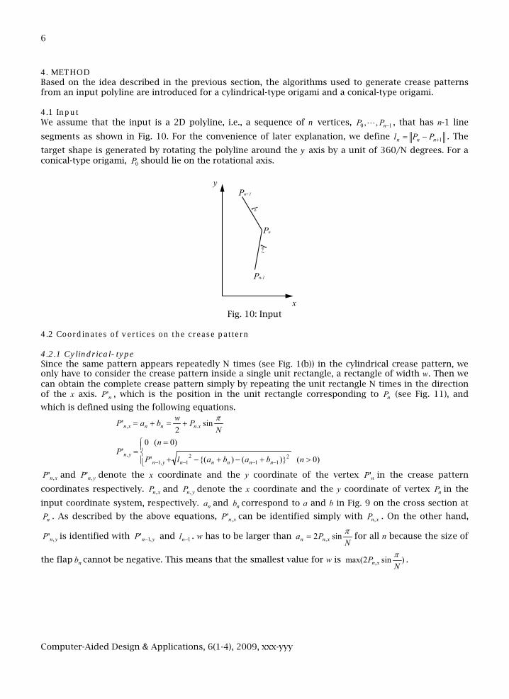
4. METHOD Based on the idea described in the previous section, the algorithms used to generate crease patterns from an input polyline are introduced for a cylindrical-type origami and a conical-type origami. 4.1 Input We assume that the input is a 2D polyline, i.e., a sequence of n vertices, 10 ,, −nPP , that has n-1 line
segments as shown in Fig. 10. For the convenience of later explanation, we define 1+−= nnn PPl . The
target shape is generated by rotating the polyline around the y axis by a unit of 360/N degrees. For a conical-type origami, 0P should lie on the rotational axis.
Pn+1
Pn-1
Pn
y
x Fig. 10: Input
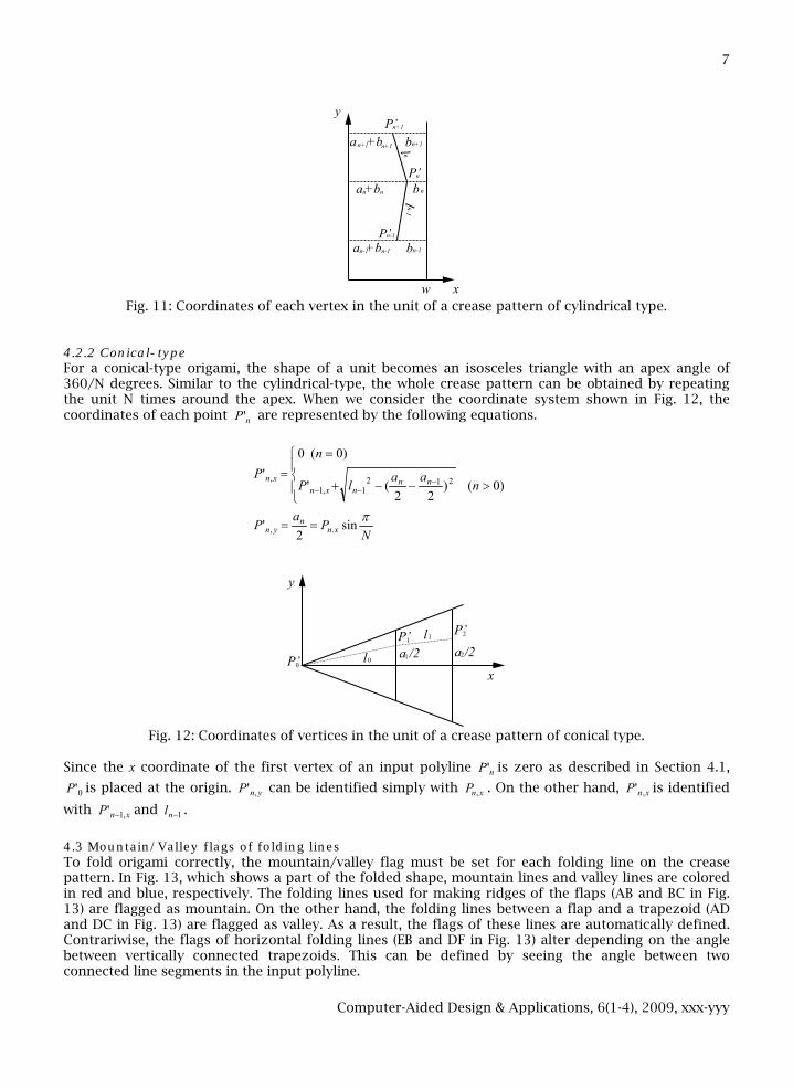
4.2 Coordinates of vertices on the crease pattern 4.2.1 Cylindrical-type Since the same pattern appears repeatedly N times (see Fig. 1(b)) in the cylindrical crease pattern, we only have to consider the crease pattern inside a single unit rectangle, a rectangle of width w. Then we can obtain the complete crease pattern simply by repeating the unit rectangle N times in the direction of the x axis. nP' , which is the position in the unit rectangle corresponding to nP (see Fig. 11), and
which is defined using the following equations.
NPwbaP xnnnxn
πsin2
' ., +=+=
>+−+−+
==
−−−− )0()}(){('
)0(0'
211
21,1
,nbabalP
nP
nnnnnynyn
xnP ,' and ynP ,' denote the x coordinate and the y coordinate of the vertex nP' in the crease pattern
coordinates respectively. xnP , and ynP , denote the x coordinate and the y coordinate of vertex nP in the
input coordinate system, respectively. na and nb correspond to a and b in Fig. 9 on the cross section at
nP . As described by the above equations, xnP ,' can be identified simply with xnP , . On the other hand,
ynP ,' is identified with ynP ,1' − and 1−nl . w has to be larger than N
Pa xnnπsin2 ,= for all n because the size of
the flap nb cannot be negative. This means that the smallest value for w is )sin2max( , NP xn
π.
Computer-Aided Design & Applications, 6(1-4), 2009, xxx-yyy
7
P’n+1
P’n-1
P’n
y
xw
a +b bn n n
a +bn-1 n-1 bn-1
a +bn+1 n+1 bn+1
Fig. 11: Coordinates of each vertex in the unit of a crease pattern of cylindrical type.
4.2.2 Conical-type For a conical-type origami, the shape of a unit becomes an isosceles triangle with an apex angle of 360/N degrees. Similar to the cylindrical-type, the whole crease pattern can be obtained by repeating the unit N times around the apex. When we consider the coordinate system shown in Fig. 12, the coordinates of each point nP' are represented by the following equations.
>−−+
=
=−
−− )0()22
('
)0(0'
2121,1
, naa
lP
nP
nnnxn
xn
NPaP xn
nyn
πsin2
' ., ==
P’0
P’1 P’2
0
x
y
a /2l
1l1 a /22
Fig. 12: Coordinates of vertices in the unit of a crease pattern of conical type.
Since the x coordinate of the first vertex of an input polyline nP' is zero as described in Section 4.1,
0'P is placed at the origin. ynP ,' can be identified simply with xnP , . On the other hand, xnP ,' is identified
with xnP ,1' − and 1−nl .
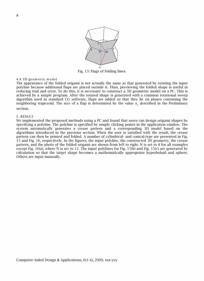
4.3 Mountain/Valley flags of folding lines To fold origami correctly, the mountain/valley flag must be set for each folding line on the crease pattern. In Fig. 13, which shows a part of the folded shape, mountain lines and valley lines are colored in red and blue, respectively. The folding lines used for making ridges of the flaps (AB and BC in Fig. 13) are flagged as mountain. On the other hand, the folding lines between a flap and a trapezoid (AD and DC in Fig. 13) are flagged as valley. As a result, the flags of these lines are automatically defined. Contrariwise, the flags of horizontal folding lines (EB and DF in Fig. 13) alter depending on the angle between vertically connected trapezoids. This can be defined by seeing the angle between two connected line segments in the input polyline.
Computer-Aided Design & Applications, 6(1-4), 2009, xxx-yyy
8
F0 F1
P
A
C
B
C
DE F
Fig. 13: Flags of folding lines.
4.4 3D geometric model The appearance of the folded origami is not actually the same as that generated by rotating the input polyline because additional flaps are placed outside it. Thus, previewing the folded shape is useful in reducing trial and error. To do this, it is necessary to construct a 3D geometric model on a PC. This is achieved by a simple program. After the rotated shape is generated with a common rotational sweep algorithm used in standard CG software, flaps are added so that they lie on planes containing the neighboring trapezoid. The size of a flap is determined by the value nb described in the Preliminary
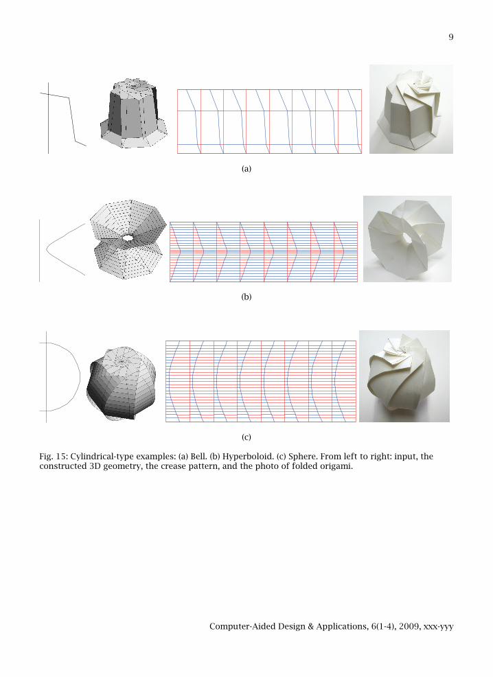
section. 5. RESULT We implemented the proposed methods using a PC and found that users can design origami shapes by specifying a polyline. The polyline is specified by simply clicking points in the application window. The system automatically generates a crease pattern and a corresponding 3D model based on the algorithms introduced in the previous section. When the user is satisfied with the result, the crease pattern can then be printed and folded. A number of cylindrical- and conical-type are presented in Fig. 15 and Fig. 16, respectively. In the figures, the input polyline, the constructed 3D geometry, the crease pattern, and the photo of the folded origami are shown from left to right. N is set to 8 for all examples except Fig. 16(a), where N is set to 12. The input polylines for Fig. 15(b) and Fig. 15(c) are generated by calculation so that the target shape becomes a mathematically appropriate hyperboloid and sphere. Others are input manually.
Computer-Aided Design & Applications, 6(1-4), 2009, xxx-yyy
9
(a)
(b)
(c) Fig. 15: Cylindrical-type examples: (a) Bell. (b) Hyperboloid. (c) Sphere. From left to right: input, the constructed 3D geometry, the crease pattern, and the photo of folded origami.
Computer-Aided Design & Applications, 6(1-4), 2009, xxx-yyy
10
(a)
(b)
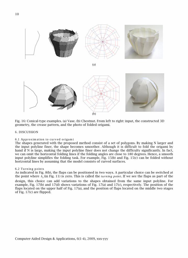
Fig. 16: Conical-type examples. (a) Vase. (b) Chestnut. From left to right: input, the constructed 3D geometry, the crease pattern, and the photo of folded origami. 6. DISCUSSION 6.1 Approximation to curved origami The shapes generated with the proposed method consist of a set of polygons. By making N larger and the input polyline finer, the shape becomes smoother. Although it is difficult to fold the origami by hand if N is large, making the input polyline finer does not change the difficulty significantly. In fact, we can omit the horizontal folding lines if the folding angles are close to 180 degrees. Hence, a smooth input polyline simplifies the folding task. For example, Fig. 15(b) and Fig. 15(c) can be folded without horizontal lines by assuming that the model consists of curved surfaces. 6.2 Turning points As indicated in Fig. 8(b), the flaps can be positioned in two ways. A particular choice can be switched at the point where nb (in Fig. 11) is zero. This is called the turning point. If we see the flaps as part of the
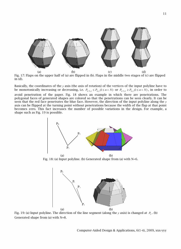
design, this choice can add variations to the shapes obtained from the same input polyline. For example, Fig. 17(b) and 17(d) shows variations of Fig. 17(a) and 17(c), respectively. The position of the flaps located on the upper half of Fig. 17(a), and the position of flaps located on the middle two stages of Fig. 17(c) are flipped.
Computer-Aided Design & Applications, 6(1-4), 2009, xxx-yyy
11
(a) (b) (c) (d) Fig. 17: Flaps on the upper half of (a) are flipped in (b). Flaps in the middle two stages of (c) are flipped in (d).
Basically, the coordinates of the y axis (the axis of rotation) of the vertices of the input polyline have to be monotonically increasing or decreasing, i.e. )1(,,1 NnPP ynyn <≤≤− or )1(,,1 NnPP ynyn <≤≥− , in order to
avoid penetration of the paper. Fig. 18 shows an example in which there are penetrations. The polygonal faces of generated shapes are colored so that the penetrations can be seen clearly. It can be seen that the red face penetrates the blue face. However, the direction of the input polyline along the y axis can be flipped at the turning point without penetrations because the width of the flap at that point becomes zero. This fact increases the number of possible variations in the design. For example, a shape such as Fig. 19 is possible.
P0
P1
P2
(a) (b)
Fig. 18: (a) Input polyline. (b) Generated shape from (a) with N=6.
P
P
PP
0
2
1
3
(a) (b) Fig. 19: (a) Input polyline. The direction of the line segment (along the y axis) is changed at 2P . (b)
Generated shape from (a) with N=8.
Computer-Aided Design & Applications, 6(1-4), 2009, xxx-yyy
12
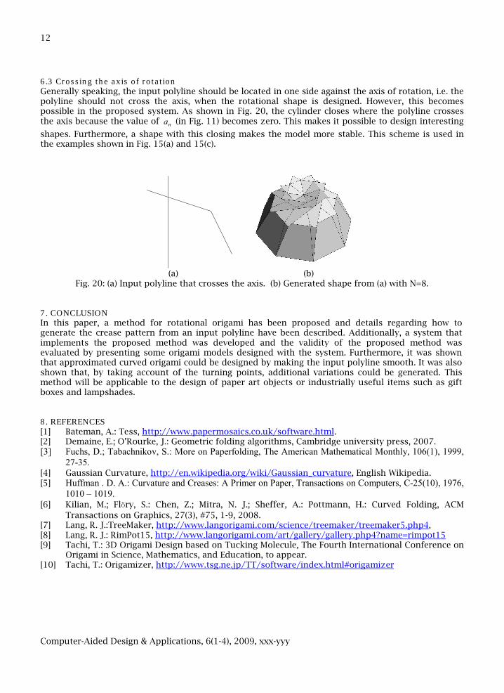
6.3 Crossing the axis of rotation Generally speaking, the input polyline should be located in one side against the axis of rotation, i.e. the polyline should not cross the axis, when the rotational shape is designed. However, this becomes possible in the proposed system. As shown in Fig. 20, the cylinder closes where the polyline crosses the axis because the value of na (in Fig. 11) becomes zero. This makes it possible to design interesting
shapes. Furthermore, a shape with this closing makes the model more stable. This scheme is used in the examples shown in Fig. 15(a) and 15(c).
(a) (b)
Fig. 20: (a) Input polyline that crosses the axis. (b) Generated shape from (a) with N=8. 7. CONCLUSION In this paper, a method for rotational origami has been proposed and details regarding how to generate the crease pattern from an input polyline have been described. Additionally, a system that implements the proposed method was developed and the validity of the proposed method was evaluated by presenting some origami models designed with the system. Furthermore, it was shown that approximated curved origami could be designed by making the input polyline smooth. It was also shown that, by taking account of the turning points, additional variations could be generated. This method will be applicable to the design of paper art objects or industrially useful items such as gift boxes and lampshades. 8. REFERENCES [1] Bateman, A.: Tess, http://www.papermosaics.co.uk/software.html. [2] Demaine, E.; O’Rourke, J.: Geometric folding algorithms, Cambridge university press, 2007. [3] Fuchs, D.; Tabachnikov, S.: More on Paperfolding, The American Mathematical Monthly, 106(1), 1999,
27-35. [4] Gaussian Curvature, http://en.wikipedia.org/wiki/Gaussian_curvature, English Wikipedia. [5] Huffman . D. A.: Curvature and Creases: A Primer on Paper, Transactions on Computers, C-25(10), 1976,
1010 – 1019. [6] Kilian, M.; Flöry, S.: Chen, Z.; Mitra, N. J.; Sheffer, A.: Pottmann, H.: Curved Folding, ACM
Transactions on Graphics, 27(3), #75, 1-9, 2008. [7] Lang, R. J.:TreeMaker, http://www.langorigami.com/science/treemaker/treemaker5.php4, [8] Lang, R. J.: RimPot15, http://www.langorigami.com/art/gallery/gallery.php4?name=rimpot15 [9] Tachi, T.: 3D Origami Design based on Tucking Molecule, The Fourth International Conference on
Origami in Science, Mathematics, and Education, to appear. [10] Tachi, T.: Origamizer, http://www.tsg.ne.jp/TT/software/index.html#origamizer