Embed Size (px)
Citation preview
A DESCRIPTION OF THE ARCHITECTURE OF A VOICE I/O EVALUATIONSYSTEM AND ITS APPLICATION IN A MILITARY JET AIRCRAFT.
Captain Claude Y. LaporteAssistant Professor
Director of the Microprocessor Applications LaboratoryCollege m11itaire royal de Saint-Jean
Saint-Jean-sur-RichelieuProvince de Quebec, Canada
JOJ IRO
This paper describes the architecture of a Voice I/Oevaluation system designed around the Standard bus. Fourspeech synthesizers and a'speech recognition modules aredescribed. Finally, the application of the Voice I/Oevaluation system to the control of radios in a militaryjet aircraft is discussed.
INTRODUCTION
In the last two years, there have been an increasingnumber of requests for projects about the application ofvoice input/output technology. It all started when sections of the department of defence first requestedinformation about speech intelligibility. Then sections
,requested demonstrations of different speech techniques,and "finally they, requested an evaluation unit so theycould test a particular applicati~n. Some applicationswere static applications where the evaluation unit wasnot moved around while other applications needed a smallportable unit' that could easily be carried around. Itwas with these criteria in mind that we designed anevaluation unit. '
An evaluation system has three desirable qualities:it should be flexi~le, easy to use and inexpensive.Ideally it should also be small and easily transportable. The proposed speech evaluation system is designedaround a bus widely used within industry: the StandardBus (STD) Bus. This bus was selected because it canacc01Dodate most S-bit microprocessors, its boards havesmall physical dimensions and the're is a wide diversityof functionnal boards available.
THE STANDARD BUS
In the mid 60' 8 a group of manufacturers decided
upon a system bus architecture which would be sui tablefor industrial applications. The result of their work isa bus description covering electrical, mechanical andcommunication specifications. Any manufacturer canproduce a component ranging from a simple board connectorto a microprocessor board that can be fully compatiblewith products from all the other manufacturers. As anexample, 25 manufacturers of CPU modules produce over 60different CPU boards.
Briefly, the STD' bus can accomodate most 8-bitmicroprocessors (S085, Z80, 6800, 6809, 6502 etc.) andeven S-bit versions of the more powerful16-bit microprocessors like the 68008 and the 8088. ,The 56-pin busis divided in five groups: 8 pins for the data bus J 16pins for the address bus, 22 pins for the control bus and6 pins for the logic power bus and 4 pins for theauxiliary power bus. The power bus can accomodate bothdigital and analog power distributions. All digitalsignals on the busses are TTL compatible. Physically,the boards are small: 16.5 cm by 11.4 em (6.5" by4.5"). In addition to the wide diversity of CPU boardsthere is a wide variety of support modules: RAM, EPROM,EEPROM, bubble memory, Analog to Digital (A/D) convertersand Digital to Analog (n/A) converters, digital Input/Output port s, serial communicat ion ,interface etc. Themodules can be purchased separatly or as' a developmentsystem with floppy or hard disks.
DESCRIPTION OF THE VOICE I/O EVALUATION SYSTEM
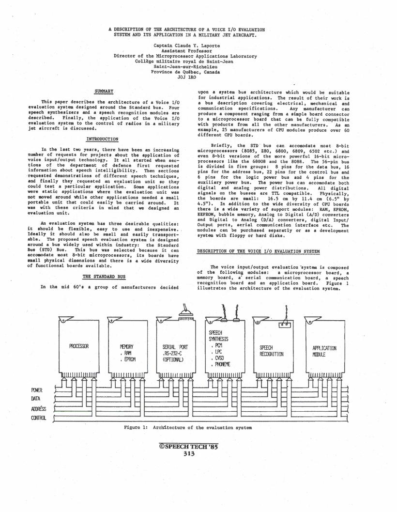
The voice input/output evaluation ~system is composedof the following modules: a microprocessor board, amemory board, a# serial communication board, a speechrecognition board and an application board. Figure 1illustrates the architecture of the evaluation system.
•
SERIAL '~T
.RS-232-C«(PfHJWJ
SFffCHSYNTl£SIS, PC11.lPC• CVSD• fID€I£
SPEECHRECffiN ITJ(J~
APPLICAT100rmul£
Figure 1: Architecture of the evaluation sY$tem
@SPEECH TECH '85313
The ~icroprocessor module
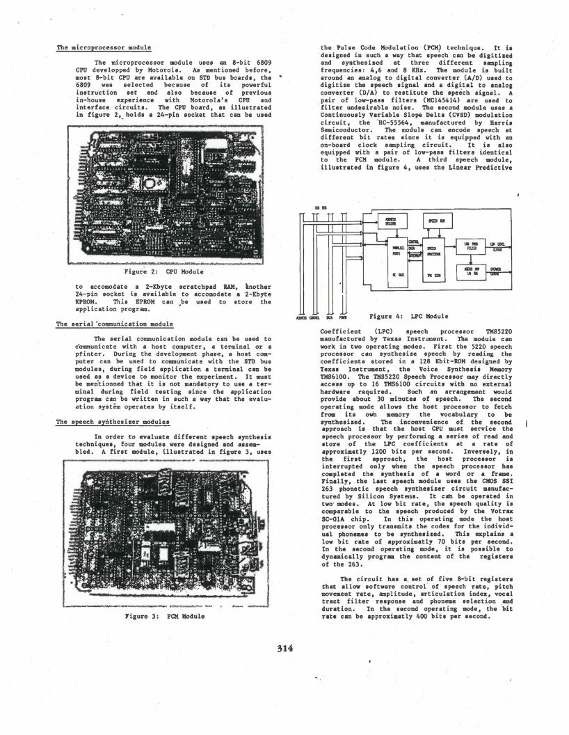
The microprocessor module uses ~n 8-bit 6809CPU developped by Motorola. As mentioned before,most 8-bitCPU are available on STD bus boards, the6809 was selected because of its powerfulinstruction set and ,also because of previousin-house experience with Motorola's CPU andinterface circuits. The CPU board, as illustratedin figure 2~ holds a 24-pin socket that can be used
Figur~ 2: CPU Module
to accomodate a 2-Xbyte scratchpad RAM, lnother24-pin socket is avai labieto accomodate ,a 2-KbyteEPROM. This EPROM can be used to store theapplication program. ~
The serial ·communication module
The serial communication module can be used toc"onununicate with a host computer, a terminal or aptinter. During the development phase,a host computer can be' used to communicate with the STD busmodules, during field application a terminal can beused, as a, device to monitor the experiment. It mustbe meritionned that it is not mandat~ry to use a terminal during field testing since the applicationprogram can be written in such a way that the evaluation system operates by itself.
The speech synthesizer modules
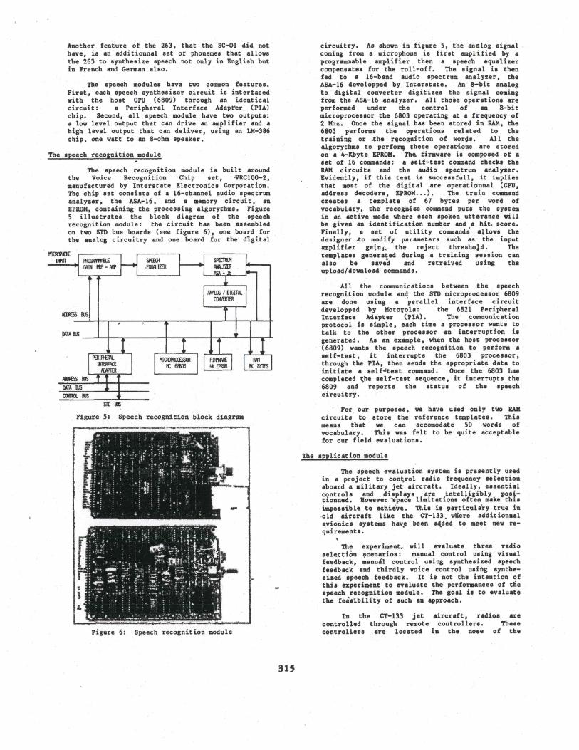
In order to evaluate different speech synthesistechniques, four modules were designed and assembled. A first module, illustrated in figure 3, uses
Figure 3: PCM Module
314
the Pulse Code Modulation (PCM) technique. It isdesigned in-such a way that 8pe~ch can be digitizedand synthesized at three different samplingfrequencies: 4,6 and 8 KHz. The module i,s builtaround an analog to digital converter (A/D) used todigitize the speech signal and a digital to analogconverter (n/A) to restitute the 8pe~ch signal. Apair of low-pass fi1 ters (MCI45414) are used tofilter undesirable noise. The second module uses aContinuously Variable-Slope Delta (CVSD) modulationcircuit, the 'HC-55564, manufactured by HarrisSemiconductor. The module can encode speech atdifferent bit rates since it is equipped with anon-bo~rd clock sampling circuit. It is alsoequipped with a pair of low-pass filters identicalto the PCK module. A third speech module,illustrated in figure 4, uses the Linear Predictive
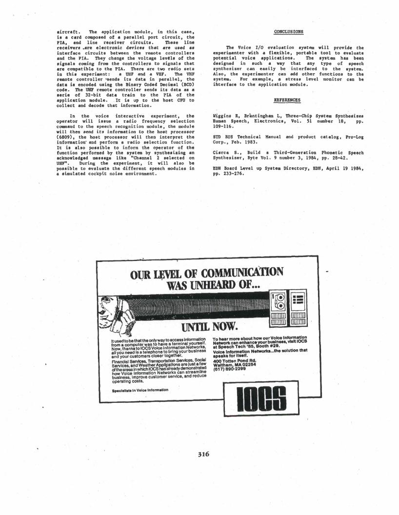
Coefficient (LPC) speech processor TMS5220manufactured by Texas Instrument. The module canwork in two operating modes. First the 5220 speechprocessor can synthesize speech by reading thecoefficients stored in a 128 Kbit-ROM designed byTexas Instrument, the Voice .Synthesis MemoryTMS6100. The TMS5220 Speech Processor may directlyaccess up to 16 TMS6I00 circuits with no externalhardware requir~d. Such an arrangement would,provide about 30 minutes of speech. The secondoperat ing mode allows the h'ost processor to fetchfrom its own memory the vocabulary to besynthesized. The inconvenience of the secondapproach is that the host CPU must service thespeech processor by performing a series of read andstore of the LPC coefficients at a rate ofapproximat ly 1200 bits per second. Inversely, inthe first approach, the host processor isinterrupted only when the speech processor hascompleted the synthesis of a Word or a ,frame.Finally, the last speech module uses the CMOS SSI263 phonetic speech synthesizer circuit manufactured by Silicon Systems. It cab be operated intwo' modes. At low bit rate, the speech quality iscomparable to the speech produced by the VotraxSC-OlA chip. In this operat ing mode the bast'processor only transmits the codes for the individual phonemes to be synthesized. This ~xplain8, alow bit rate of approximatly 70 bits per second.In the second operating mode , it is 'possible todynamically program the content of the registersof the 263.
The circuit has a. set of five 8-bit registersthat allow software control' of speech rate, pitchmovement rate, amplitude, articulation index, vocaltract filter response and phoneme selection and
, duration. In the second operating mode, the 'bitrate can be approximatly 400 bits per second.
"
All the communications between the speechrecognition module and the STD microprocessor 6809are don'e using a 'parallel interface circuitdevelopped by Motolola: the 6821 Peri pheralInterface Adapter (PIA.) • The. cOl'DDunicationprotocol is simple, each time a processor wants totalk to the other processor ·an interruption isgenerated. As an example ,when the host processor(6809) want·s the speech recognition to perform asel f-test, it interrupts the 6803 processor t
through the PIA, then sends the appropriate data toini tiate a sel f~te8t coumand, Once the 6803 hascompleted ts.he self-test sequence, it interrupts the6809 and reports the status of the speechcircuitry.
. Fot. our purposes, we have used only two RAMcircuits to store the reference. templates. Thismeans that we can accomodate 50 words ofvocabulary. This was felt to be quite acceptablefor our field evaluations.
The experiment~ will evaluate three radioselection ,cenarios: manual control using visualfeedback, manutl control using synthesized speechfeedback 'and thirdly voice control using synthesized speech feedback. It is not the intention ofthis experiment to evaluate the performances of thespeech recognition module. The goal i. to evaluatethe fea.~bility of such an approach.
In the CT-133 jet aircraft, radios arecontrolled through remote controllers. Thesecontrollers are located i,n the nose of the
circuitry. As shown in figure 5, the analog signalcoming from a microphone is first ampl ified by aprogrammable amplifier then 8. speech equalizercompensates for the roll-off. The signal is thenfed to a 16-band audio spectrum analyzer, theASA-16 developped by. Interstate. An a-bit analogto digital converter digitizes the signal comingfrom the ASA-16 analyzer. All those operations areperformed under the control of an 8-bitmicroprocessor the 6803 operating at a frequency of2 Mhz. Once the signal has been stored in RAM, the6803 performs the operations related to thetraining or ..the r~cognition 0_£ worps, All thealgorythms to perf0rtll these operat~ons are storedon a 4-Kbyte EPROM. Tb~, firmware is composed of aset of 16 commands: a self-test command checks theRAM circuits and the audio spectrum analyzer.Evidently, if this test is successfull, it impliesthat most of the digital are operationnal (CPU,address decoders, EPROM ••• ). The train commandcreates a template of 67 bytes per word' ofvocabulary, the recognize command puts the systemin an active mode where each spoken utterance willbe given an· ident i fication number and a hit~ score.Finally, a set of utility commands 8+lows thedesigner .to modify parameters such as the inputamplifier gainh the reject threshold. Thetemplates generated during a training session canalso be saved and retreived using theupload/download commands.
The application module
The speech evaluation system is presently usedin a project to control radio frequency selectionaboard a military jet aircraft. Ideally, essentialcqntrol. and displays. are .int-elligibly pos~t10nned, Bowever~pace llmltat10ns often make th1Simpossible to achieve. This is particulary true ~n
,old aitcraft like the CT-133~ wnere additionnalavionic. sy8tems hav'!Ie been aq,.ded to meet new requirements.
. I,
~~~~~
The speech recognition module is built aroundthe Voice Recognition Chip set, ~RC100-2,
manufactured by Interstate Electronics Corporation.Th~ chip set consists of a l6-channel audio spectrumanalyzer, the ASA-l6, and a memory circuit, anEPROM, containing the processing algorythms. Figure5 illustrates the bloc~ diagram of the speechrecognition module: the 'circuit has been assembledon two STD bus boards (see figure 6), one board forthe analog circuitry and one board for the dIgital
The speech modules have t\lJO common features.First, each speech synthesizer circuit is interfacedwith the host CPU (6809) through an identicalcircuit: a Peripheral Interface Adapter (PIA)chip. Second, all speech module have two outputs:a low level output that can drive an amplifier and ahigh level output that can deliver, using an LM-386chip, one watt to an 8-ohm speaker.
Figure 6: Speech recognition module
Another feature of the 263, that the SC-Ol did notbave, is an additionnal set of pbon~me8 that allowsthe 263 to synthesize speech not only in English butin French and German also.
STDIl.5
Figure 5: Speech recognition block diagram
MTA IJ1)
AIDESS BJS
.D\TA 11.5 ---.l----+----,r-----+--.......-----+--r-.-A--f----.wr--
The speech recognition module
315
aircraft. The application module. in this case,is a card composed of a parallel port circuit, thePIA, and line receiver circuits. These linereceivers ~are electronic devices that are used asinterface circuits between the remote controllersand the PIA. They change the voltage levels of thesignals coming from the controllers to signals thatare compatible to the PIA. There are two radio setsin this experiment: a UHF and a VHF. The VHFremote controller ~$ends its data in parallel, thedata is encoded using the Binary Coded Decimal (BCD)code. The UHF remote controller sends its data as aserie of 32-bit data train to the PIA of theapplication module. . It is up to the host CPU tocollect and decode that information.
CONCLUSIONS
The Voice I/O evaluation system will provide theexperimenter with a flexible J portable tool to evaluatepotential voice applications. The system has beendesigned in such a way that any type of speechsynthesizer can easily be 'interfaced to the system.Also, the experimenter can ~dd other functions to thesystem. For example, a stress level monitor can beihterface to the application module.
REFERENCES
In the voice interactive experiment. theoperator will issue a radio frequency selectioncommand to the speech recognition module, the module
,will then send its infQrmation to the host processor(6809). the host processor will then interpret theinformation" and perform a radio selection function.It is also possible to inform the operator of thefunction performed by the system by synthesizing anacknowledged message like "Channel 2 selected onUHF". During the expet'iment, it will also bepossible to eva1u~te the different speech modules ina simulated cockpit noise environment.
Wiggins R, Brantingham L, Three-Chip System SynthesizesHuman Speech, Electronics, Vol. 51 number 18, pp.109-116.
STD BUS Technical Manual and product catalog. Pro-LogCorp., Feb. 1983.
eiarcs S., Build a Third-Generation Phonetic SpeechSynthesizer, By~e Vol. 9 number 3, 1984, pp. 28-42.
EDN Board Level up System Directory, EDN, April 19 1984,pp. 233-276.
1119
To hear more about how our Voice InformationNetwork can enhanceyour business. visit IOCSat Speech Tech '85. Booth #29.Voice Information Networks•••the solution thatapeake for Itself.400 Totten Pond Rd.Waltham.! MA 02254(617) 89u·2299
SpeclaU.tl In Voice Information
tJLr-J/\ "~
It used to'be that the onlyway toaccess Informationfrom a computer was to have a terminal yourself.Now thanks to IOCSVoice Informatlon Networks,all you need is a telephone to bring your businessand your customers closer together.Rnanc!sl Services, Transportation Services. SocialServices, and Weather Applifatlons are just a fewoftheareas Inwhich lOGShasalreadydemonstratedhow Voice Information Networks can stream((nebusiness, Improve customer service, and reduceoperating costs.
OUR LEVEL OF COMMUNIcATION. ' · WAS UNHFARDrOF•••
316