Embed Size (px)
Citation preview
This is a n Op e n Acces s doc u m e n t dow nloa d e d fro m ORCA, Ca r diff U nive r si ty 's
ins ti t u tion al r e posi to ry: h t t p s://o rc a.c a r diff.ac.uk/122 7 5 8/
This is t h e a u t ho r’s ve r sion of a wo rk t h a t w as s u b mi t t e d to / a c c e p t e d for
p u blica tion.
Cit a tion for final p u blish e d ve r sion:
Liu, Ch ao, Veng ayil, H ris hike s h, Lu, Yuqian a n d Xu, Xun 2 0 1 9. A cyb e r-
p hysical m a c hin e tools pl a tfo r m u sing OPC UA a n d MTCon n e c t . Jour n al of
M a n ufac t u rin g Sys t e m s 5 1 , p p. 6 1-7 4. 1 0.10 1 6/j.jmsy.201 9.04.00 6 file
P u blish e r s p a g e: h t t p://dx.doi.o rg/10.10 1 6/j.jmsy.2019.04.00 6
< h t t p://dx.doi.o rg/10.10 1 6/j.jmsy.2019.0 4.00 6 >
Ple a s e no t e:
Ch a n g e s m a d e a s a r e s ul t of p u blishing p roc e s s e s s uc h a s copy-e di ting,
for m a t ting a n d p a g e n u m b e r s m ay no t b e r eflec t e d in t his ve r sion. For t h e
d efini tive ve r sion of t his p u blica tion, ple a s e r ef e r to t h e p u blish e d sou rc e. You
a r e a dvise d to cons ul t t h e p u blish e r’s ve r sion if you wish to ci t e t his p a p er.
This ve r sion is b ein g m a d e av ailable in a cco r d a n c e wit h p u blish e r policie s.
S e e
h t t p://o rc a .cf.ac.uk/policies.h t ml for u s a g e policies. Copyrigh t a n d m o r al r i gh t s
for p u blica tions m a d e available in ORCA a r e r e t ain e d by t h e copyrig h t
hold e r s .
A Cyber-Physical Machine Tools Platform using OPC UA and
MTConnect
Chao Liua, Hrishikesh Vengayila, Yuqian Lub, and Xun Xua*
a Department of Mechanical Engineering, University of Auckland, Auckland 1010, New Zealand
b FRAMECAD Ltd, Auckland 1072, New Zealand
*Corresponding author: [email protected]
ABSTRACT: Cyber-Physical Machine Tools (CPMT) represent a new generation of
machine tools that are smarter, well connected, widely accessible, more adaptive and more
autonomous. Development of CPMT requires standardized information modelling method
and communication protocols for machine tools. This paper proposes a CPMT Platform
based on OPC UA and MTConnect that enables standardized, interoperable and efficient data
communication among machine tools and various types of software applications. First, a
development method for OPC UA-based CPMT is proposed based on a generic OPC UA
information model for CNC machine tools. Second, to address the issue of interoperability
between OPC UA and MTConnect, an MTConnect to OPC UA interface is developed to
transform MTConnect information model and data to their OPC UA counterparts. An OPC
UA-based CPMT prototype is developed and further integrated with a previously developed
MTConnect-based CPMT to establish a CPMT Platform. Third, different applications are
developed to demonstrate the advantages of the proposed CPMT Platform, including an OPC
UA Client, an advanced AR-assisted wearable Human-Machine Interface and a conceptual
framework for CPMT powered cloud manufacturing environment. Experimental results have
proven that the proposed CPMT Platform can significantly improve the overall production
efficiency and effectiveness in the shop floor.
Key words: Cyber-Physical Machine Tools; Machine Tool 4.0; digital twin; OPC UA;
MTConnect
1. INTRODUCTION
Machine tools play a vital role in the realm of manufacturing in that their performances
significantly impact on production efficiency and effectiveness. In response to the
requirements of Cyber-Physical Production Systems (CPPS) [1,2] and Smart Factory[3–6],
there exists an urgent need to advance existing Computer Numeric Control (CNC) machine
tools to a higher level of connectivity, accessibility, intelligence and autonomy. In this
context, Machine Tool 4.0 [7] was proposed as a new technological evolution of machine
tools triggered by recent advancements of Information and Communication Technologies
(ICT) such as Cyber-Physical Systems (CPS), Internet of Things (IoT) and cloud technology.
In general, Machine Tool 4.0 defines a new generation of machine tools that are smarter, well
connected, widely accessible, more adaptive and more autonomous [8]. Xu [7] proposed
three new types of machine tools as the possible solutions of Machine Tool 4.0, namely
Cyber-Physical Machine Tools (CPMT), vertically-integrated machine tools, and
horizontally-integrated machine tools.
• CPMT refers to the integration of the machine tool, machining processes, computation
and networking, where embedded computations monitor and control the machining
processes, with feedback loops in which machining processes can affect computations
and vice versa.
• Vertically-integrated machine tools are those that can support end-to-end digital
integration throughout the engineering process encompassing design, process
planning, manufacturing, assembly, and so forth. Model-based manufacturing such as
STEP-NC-enabled CAD/CAM/CNC integration [9,10] is one of the key enabling
technologies;
• Horizontally-integrated machine tools refer to machine tools that are interconnected
with other manufacturing facilities and resources (e.g. robots, conveyors, measurement
devices, enterprise resource planning systems) through semantics-enabled machine-to-
machine (M2M) communications, eventually leading towards a cooperative production
system.
The focus of this research is on CPMT. In general, CPMT is a CPS-based machine tool
which has the characteristics of a typical CPS, such as network connectivity, adaptability,
predictability, intelligence, with real-time feedback loops and with humans in the loop [11].
With extensive real-time machining data and computations deeply integrated with machine
tool and machining processes, CPMT provides various types of feedback loops such as
autonomous feedback control, shop floor decision-making support and cloud-based analytics;
all intend to improve the performance, efficiency and effectiveness of a machine tool. The
core of a CPMT, as well as the most significant advancement of CPMT compared to
traditional CNC machine tools, lies in its Machine Tool Digital Twin (MTDT). MTDT refers
to the digital twin of the machine tool that is capable of: (1) representing the characteristics
and real-time status of the machine tool, (2) monitoring and controlling the machine tool with
built-in computation and intelligence, and (3) sending the shop-floor manufacturing data to
different Human-Machine Interfaces (HMIs) as well as the cloud to provide efficient
decision-making support for different users.
Modelling of the MTDT is a challenging task. Firstly, CNC machine tools are complex
systems comprising various types of components and peripheral devices. Different types and
brands of machine tools may have different structures and components. In order to
comprehensively and intuitively represent a physical machine tool in the cyber world, a
generic information model for machine tools representing the logical structure as well as the
real-time status of each critical component of the machine tool must be developed. Secondly,
a large amount of different types of real-time machining data obtained from various types of
data acquisition devices (e.g. CNC controller, RFID tags, power meters, accelerometers,
dynamometers, acoustic emission sensors) presents a great challenge in data communication,
management and analytics. Open, unified and cross-platform communication standards must
be implemented to address these issues. Recently, MTConnect [12] and OPC UA [13] have
both shown great capabilities in terms of information modelling and real-time data exchange
for manufacturing systems. Both MTConnect and OPC UA are open and royalty free
communication standards designed for industrial automation. MTConnect provides a concrete
information modelling method specifically designed for CNC machine tools with some
predefined data structures and rules, whereas OPC UA offers a more generic information
modelling method in order to cover a broader range of industrial equipment and systems.
In our previous work presented in [14], a systematic development method based on a
generic system architecture for CPMT was proposed to provide the guidance on advancing
CNC machine tools to CPMT. An MTConnect-based CPMT prototype was developed to
demonstrate the feasibility and capability of the proposed CPMT. In this paper, we propose a
CPMT Platform based on both OPC UA and MTConnect. Firstly, the development method
for OPC UA-based CPMT is proposed. The system architecture and generic OPC UA-based
information modelling method for CPMT are studied. An OPC UA-based CPMT prototype is
developed based on a 3-axis CNC milling machine (EMCO Concept Mill 105) to validate the
feasibility of the proposed method. Secondly, a CPMT Platform that is compatible with both
OPC UA and MTConnect is proposed. Communication interfaces between OPC UA and
MTConnect are developed. A prototype of the CPMT Platform is established by integrating
the OPC UA-based CPMT prototype with the previously developed MTConnect-based
CPMT prototype. Furthermore, an advanced wearable HMI with Augmented Reality (AR)-
assisted process monitoring and simulation functions, and a conceptual framework for CPMT
powered cloud manufacturing environment are introduced to demonstrate the potential of the
CPMT Platform.
The remainder of this paper is organized as follows. Section 2 reviews the state-of-art
work related to digital twin technologies as well as the implementation of OPC UA. Section 3
introduces the proposed OPC UA-based CPMT, including a generic information modelling
method and an OPC UA-based CPMT prototype. The CPMT Platform is proposed in Section
4, and the integration of OPC UA- and MTConnect-based CPMT is demonstrated through a
case study. Section 5 briefly introduces two applications for the CPMT Platform. Conclusions
are given in Section 6.
2. LITERATURE REVIEW
Digital twin is a key component of any CPS. The core of a CPMT lies in its MTDT.
Development of MTDT requires standardized information modelling technology and
communication protocol. This research utilizes OPC UA as a key enabling technology to
develop the CPMT Platform. This section reviews the state-of-the-art work on digital twin
and OPC UA related research and identifies the research gaps in this field. A brief review of
MTConnect-related work and the details of MTConnect-based CPMT can be found in [15].
2.1 Digital Twin related research
With the rapid development of CPS, the concept of digital twin (or cyber twin) has
attracted more and more attention. The term “digital twin” was initially brought to public by
NASA’s Modelling, Simulation, Information Technology & Processing Roadmap in 2010
[16]. Currently, there exist various definitions of digital twin from different perspectives such
as lifecycle management, mission requirements, prognostics and diagnostics activities, and so
forth [17]. A commonly used definition of digital twin was provided by Glaessgen and
Stargel [18], i.e. ‘Digital twin is an integrated multi-physics, multi-scale, probabilistic
simulation of a complex product and uses the best available physical models, sensor updates,
etc., to mirror the life of its corresponding twin.’
Nowadays, digital twin is considered as a key enabler for Product Lifecycle Management
(PLM), CPPS and Smart Factory in the era of Industry 4.0 [19–21]. Lee et al. [22] proposed a
conceptual CPS architecture for a manufacturing system, where each critical component has a
digital twin for capturing sensory data and synthesizing future steps. These digital twins are
then aggregated as a digital twin for a particular machine, endowing the machine with self-
awareness, self-prediction and self-comparison capabilities. Tao et al. [20] proposed a new
digital twin-driven approach to realize more efficient, smart and sustainable product design,
manufacturing and service. Tao et al. [23] proposed a five-dimension digital twin model for
the Prognostics and Health Management (PHM) of complex equipment. Advantages of the
digital twin approach compared to traditional prediction methods have been validated through
a case study of the fault cause prediction of a wind turbine. Aiming to develop digital-twins
of virtual machine tools for cyber-physical manufacturing, Cai et al. [24] presented some
techniques for extracting machining characteristics profiles using sensory data integration and
machining information fusion. However, unified communication standard and information
model were not implemented for data management. Schroeder et al. [25] presented a
methodology to model the digital twin of a manufacturing device, making use of
AutomationML at a high level. A digital twin of a valve was modelled to represent its
physical components as well as some attributes. Urbina Coronado et al. [26] proposed a Shop
Floor Digital Twin framework which represents parts, operators, capital equipment and
consumables in the shop floor and allows decision-making support for different users. A
Web-based Manufacturing Execution System (MES) was developed to collect and track
materials, cutting tool usage, operator activities and work-in-process. STEP Tools Inc. [27]
developed a digital thread solution which keeps the design, manufacturing, and inspection
data of a product connected around a digital twin. A 3D model-based machining simulator
which fuses STEP models of the product, MTConnect status of the machine tool and Quality
Information Framework (QIF) metrology feedback was developed to build the digital twin of
the product while it is being machined.
2.2 OPC UA related research
The introduction of OPC UA in CPPS architecture is essential in the context of Industry
4.0. Reference Architecture Model Industry 4.0 (RAMI 4.0) has been proposed to provide
orientations and standardization for Industry 4.0; OPC UA was the only standard being
recommended in the communication layer [28,29]. Implementation of OPC UA for Industry
4.0 is partly standardized as an international standard IEC 62541. Since OPC UA provides
both communication protocol and information modelling method, it can be readily utilized to
model the digital twins of manufacturing facilities.
In the last few years, research on the integration of OPC UA into process monitoring and
control has been extensively studied. Schlechtendahl et al. [30] proposed a holistic approach
to integrating existing production systems to the Industry 4.0 environment. OPC UA was
validated as a critical enabler for discovering existing resources, enabling data
communication through cloud-based gateways and eventually transforming current
production systems to CPPS. Garcia et al. [31] presented a low-cost CPPS architecture in
which OPC UA can be used to access field data in automation systems. An OPC UA-based
information model for a plant-floor system was also proposed. Muller et al. [32] presented an
open source and free implementation of OPC UA. A customizable OPC UA server developed
on an Arduino microcontroller board enabled a closed-loop temperature control of the nozzle
of a 3D printer. Imtiaz and Jasperneite [33] developed a Nano OPC UA server which can be
integrated into low-memory devices and at the same time possessing all the features of a
standard OPC UA server. The use of such Nano OPC UA servers demonstrated the
scalability of OPC UA in low-level IoT-based devices. Luo et al. [34] proposed a three-tier
architecture for a smart manufacturing process where OPC UA is utilized to integrate various
industrial field networks into the top-level factory energy management system. Wu et al. [35]
developed a fog computing-based platform for process monitoring and prognosis by
integrating OPC UA and MTConnect with milling machines. Ayatollahi et al. [36] developed
a semantic communication interface that allows remote control of a machine tool with a
standard OPC UA client. Sequenced control commands can be executed by dragging methods
or variables exposed by the OPC UA server. Pauker et al. [37] proposed a service
orchestration method for flexible manufacturing cells based on service-oriented architecture
(SOA) paradigm and OPC UA communication. Various services which represent the
mechatronic functions of the equipment were defined in the address space of the OPC UA
server, thus the flexibility of the manufacturing cells can be enhanced. OPC UA has also been
extensively implemented as the communication protocol in power consumption monitoring
and energy efficiency analysis systems [38–40]. Design and development of an OPC UA
information model need to follow a model-driven approach. Pauker et al. [41] proposed a
systematic and generic approach for developing an information model to represent the static
and dynamic behaviour of a manufacturing system. Developing the information model for a
complex manufacturing system requires a huge amount of programming work. Girbea et al.
[42] proposed several algorithms that aid an efficient and automatic generation of address
space in OPC UA servers. Owing to the generic and flexible information modelling method,
OPC UA has also been implemented in various types of process monitoring and control
systems in different industries such as Smart Grid [43], Oil and Gas production [44] and
Public transportation systems [45].
2.3 Research gaps
The state-of-the-art work indicates an urgent need of developing digital twins for
manufacturing devices for the realization of CPPS and Smart Factory. Previous work on
digital twin mainly focused on products, manufacturing systems or shop floors; few studies
were on machine tools. OPC UA has been extensively implemented in various types of
manufacturing devices and systems as the communication protocol. Yet, implementation of
OPC UA in machine tools is still not common. There has not been much attention paid to a
generic OPC UA-based information model for machine tools. Furthermore, although OPC
UA and MTConnect are both capable of being used for developing CPMT, they are not yet
interoperable. Given the crucial role machine tools will play in the envisioned CPPS and
Smart Factory, current CNC machine tools need to be advanced to CPMT with the
implementation of standardized information models and communication protocols. This
paper attempts to bridge these research gaps by developing a CPMT Platform. A generic
OPC UA information model for machine tools is proposed to develop an OPC UA-based
CPMT. As a part of the CPMT Platform, an interface between OPC UA and MTConnect is
developed.
3. OPC UA-BASED CYBER-PHYSICAL MACHINE TOOL
3.1 Generic system architecture of OPC UA-based CPMT
The generic system architecture for an OPC UA-based CPMT is proposed (Figure 1). This
architecture aims at providing a generic, systematic, extensible and customizable solution for
developing OPC UA-based CPMT, based on the generic CPMT architecture proposed in our
previous work [14]. This section introduces the main components and their functions in the
proposed architecture. The detailed development principles and implementation strategies
will be discussed and demonstrated in the case study that follows.
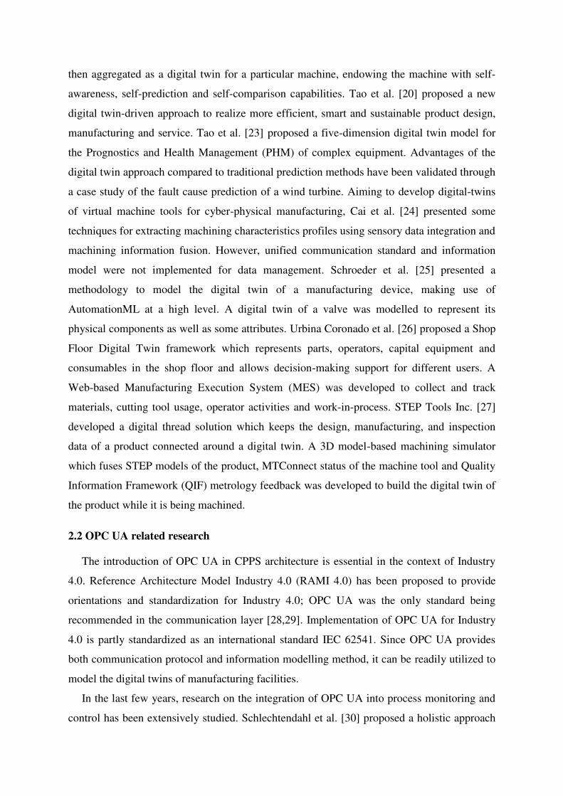
Figure 1. Generic system architecture of OPC UA-based CPMT
As shown in Figure 1, the physical devices include CNC machine tools, cutting tools,
workpieces, sensors and data acquisition devices. These physical devices are responsible for
carrying out machining tasks as well as transmitting the real-time machining data to the
MTDT. Extracting data from CNC controllers often requires vendor-dependent tools, such as
Application Programming Interfaces (APIs) or even hardware adapters. A recent trend has
been observed that more and more CNC manufacturers and third-party developers are
developing embedded OPC UA servers or OPC UA plugins for CNC controllers. For
example, Siemens has integrated the OPC UA server in their SINUMERIK 828D and 840D
controllers [46]. It can be predicted that OPC UA-based data acquisition from CNC
controllers will be made easier in the near future.
In order to comprehensively represent the machining processes in a MTDT, external
sensors are still needed to enable the provision of a more complete set of data for MTDT.
Firstly, static properties of the machine tool and its critical components (size of the
worktable, geometry of the cutting tools, etc.) need to be obtained from the shop floor. RFID
tags and readers can be used to transmit these data to the MTDT. Secondly, some critical
real-time machining data (cutting forces, vibrations, acoustic emissions, motor power, etc.)
need be collected using various types of sensors and data acquisition devices based on
specific needs of the users. These data represent the actual machining processes, hence
providing the foundation of advanced data analytics in the MTDT.
With various types of data acquisition devices implemented in the shop floor, different
networking techniques (Ethernet, WiFi, Profinet, Bluetooth, etc.) need to be implemented to
transmit the data to the MTDT. MTDT is the core of the proposed CPMT consisting of three
main modules: 1) data pre-processing, 2) OPC UA Server and 3) local OPC UA Client.
1) Data pre-processing: to reduce the amount of real-time data transferred to the OPC
UA Server, the data obtained from various sensors need to be cleansed and pre-
processed (e.g. using edge/fog computing methods) so that only useful data and
features of the sensor signals are delivered to the OPC UA Server for further analysis.
2) OPC UA Server: the OPC UA information model that represents the logical structure
of the machine tool is integrated in the OPC UA Server. Data obtained from the
physical world are correlated to the nodes in the address space and grouped to their
corresponding components in the information model. When other OPC UA Clients
require data, the OPC UA Server encodes the required data into standardized messages
(OPC UA Binary or XML defined by OPC UA standard) and sends them to the Clients
while maintaining and securing the connections.
3) Local OPC UA Clients: these are customizable OPC UA Clients embedded in the
MTDT. To achieve better real-time performance, these Clients are connected to the
Server in the local (shop floor) network. They request data from the Server, analyse
and process them with customized algorithms and provide decision-making supports
for processes such as monitoring, machining simulation and PHM.
The proposed OPC UA-based CPMT enables three types of feedback control from the
MTDT to the physical machine tool as indicated in Figure 1. In the autonomous feedback
control, control commands are directly sent to the CNC controller from the MTDT. This is
achieved by implementing real-time process optimization algorithms in local OPC UA
Clients. These clients interface with the CNC controller through specific APIs or hardware
adapters depending on the type of the controller. In the shop floor decision-making supports,
local OPC UA Clients which provide decision-making support functions (e.g. visualization,
monitoring, simulation, PHM) require the related real-time data from the OPC UA Server and
provide corresponding functions to machine operators, maintenance technicians and shop
floor managers to help them make efficient decisions during machining processes. Various
types of HMIs such as laptops, smart phones and wearable devices can be utilized as OPC
UA Clients since OPC UA is platform-independent. In the cloud-based decision-making
supports, various OPC UA Clients developed by third-party service providers can be
provided as services in the cloud. These Clients can discover and be connected to the OPC
UA Server in the MTDT in order to access the field-level manufacturing data through the
Internet. Various value-added services such as remote monitoring, historical data analytics
and production planning can be integrated into the Clients and provisioned to different users
(product designers, process planners, production managers, etc.) through the Internet.
3.2 Generic OPC UA information model for CPMT
The information modelling method provided by OPC UA is generic and flexible. In
general, OPC UA information model is represented using four main components, i.e. Objects,
Variables, Methods and References. Objects are instances of an ObjectType which is
equivalent to a Class in the Object-Oriented Programming term. ObjectType is used to define
the base structure of an information model. The instance of an ObjectType is an Object which
handles the data of the system that it is representing. Objects can contain variables and
methods as their child components, mainly for characterizing and manipulating the data.
References are used to define the relations between all these components. To build an OPC
UA information model of a device, designers need to define all these components based on
their understanding of the structure as well as the available data of the device. As a result, the
design of an OPC UA information model, even though for a same device, can vary from one
to another. In our proposed CPMT, the information model is one of the most critical
components since it represents the structure and the available data of the machine tool.
Although there exist various types of CNC machine tools, they usually follow the same
logical structure and contain the same types of data. Therefore, a generic OPC UA
information model that is particularly designed for CNC machine tools needs to be developed
to provide the guidance for information model designers.
Recently, a Companion Specification – OPC UA Information Model for CNC Systems
[47] was published by a joint working group of the OPC Foundation and the German
Machine Tool Builders’ Association (VDW). The specification defines an OPC UA
information model to interface and exchange data with CNC systems. Although this
information model contains a comprehensive set of data in CNC systems, it is not suitable for
the OPC UA-based CPMT proposed in this research. On the one hand, this information
model focuses only on the data within the CNC kernel of a CNC system. Some process data
that are necessary for modelling the MTDT, such as the data from the Programmable Logic
Controller (PLC) and external data acquisition devices of a machine tool, are not included.
On the other hand, the structure of this information model does not represent the logical
relations of all the components and subsystems in a CNC machine tool. Since MTConnect
standard has already defined a hierarchically structured data model specifically for CNC
machine tools [48], a corresponding OPC UA information model needs to be developed in
consideration of the interoperability between OPC UA- and MTConnect-based CPMT. The
requirements of the generic OPC UA information model for a CPMT are defined as follows:
1) It should be a hierarchical structure, similar to the information model defined in
MTConnect that indicates the logical relations of all the critical components and the
available data of the machine tool;
2) Data from different data sources should be grouped into their related components to
represent the static properties as well as real-time status of each component;
3) It should allow efficient mappings from MTConnect data sources to the respective
OPC UA nodes;
4) Modifications and extensions of this generic model should be easily achieved for
producing a more specific information model.
Based on these requirements, a generic OPC UA information model for CPMT is
proposed (Figure 2). Initially, TypeDefinitions (for the complete information model) need to
be defined. TypeDefinitions explain the type information of the objects and data variables
that can be obtained from a particular information model. In the proposed generic information
model, the MachineToolType of BaseObjectType is defined as a complex ObjectType
representing a CNC machine tool. It has four Properties as static string variables representing
the static properties of the machine tool, i.e. the name, manufacturer and manufacture date of
the machine and the name of its controller. MachineToolType has four SubObjectTypes as
shown in Figure 2. ControllerType contains variables for handling real-time data that can be
extracted from the CNC controller such as power status, alarms and feed rate. AxesListType
handles the nodes of three SubObjectTypes namely LinearAxesType, RotaryAxesTpe and
SpindleType. LinearAxesType and RotaryAxesType consist of variables to hold actual and
commanded positions of the axis along with the corresponding engineering unit. SpindleType
is used to handle information about the speed, override and motor power of the spindle.
CuttingToolType is used to handle the information regarding the cutting tools, such as the
identification, type, material and size of the cutting tool. Two SubObjectTypes, i.e.
ToolVibrationType and CuttingForcesType are created to handle variables representing the
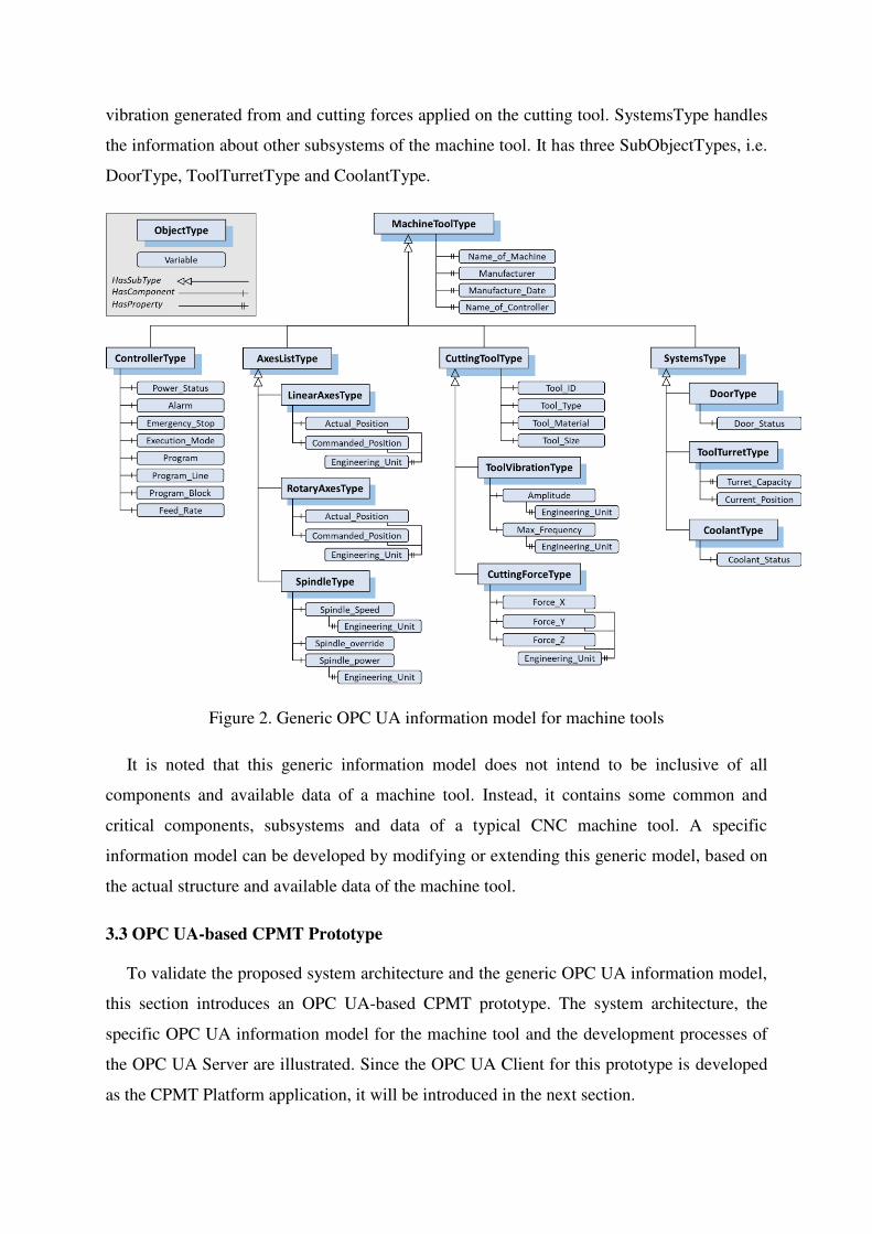
vibration generated from and cutting forces applied on the cutting tool. SystemsType handles
the information about other subsystems of the machine tool. It has three SubObjectTypes, i.e.
DoorType, ToolTurretType and CoolantType.
Figure 2. Generic OPC UA information model for machine tools
It is noted that this generic information model does not intend to be inclusive of all
components and available data of a machine tool. Instead, it contains some common and
critical components, subsystems and data of a typical CNC machine tool. A specific
information model can be developed by modifying or extending this generic model, based on
the actual structure and available data of the machine tool.
3.3 OPC UA-based CPMT Prototype
To validate the proposed system architecture and the generic OPC UA information model,
this section introduces an OPC UA-based CPMT prototype. The system architecture, the
specific OPC UA information model for the machine tool and the development processes of
the OPC UA Server are illustrated. Since the OPC UA Client for this prototype is developed
as the CPMT Platform application, it will be introduced in the next section.
3.3.1 System architecture
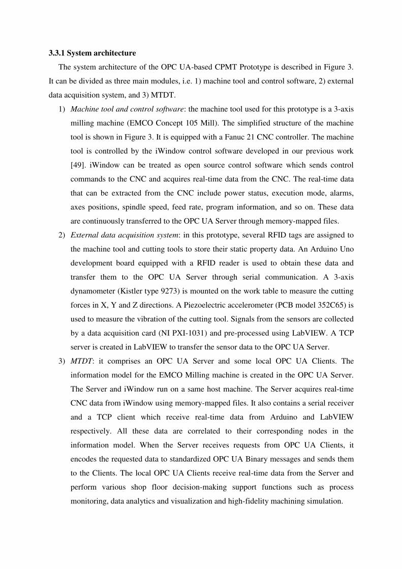
The system architecture of the OPC UA-based CPMT Prototype is described in Figure 3.
It can be divided as three main modules, i.e. 1) machine tool and control software, 2) external
data acquisition system, and 3) MTDT.
1) Machine tool and control software: the machine tool used for this prototype is a 3-axis
milling machine (EMCO Concept 105 Mill). The simplified structure of the machine
tool is shown in Figure 3. It is equipped with a Fanuc 21 CNC controller. The machine
tool is controlled by the iWindow control software developed in our previous work
[49]. iWindow can be treated as open source control software which sends control
commands to the CNC and acquires real-time data from the CNC. The real-time data
that can be extracted from the CNC include power status, execution mode, alarms,
axes positions, spindle speed, feed rate, program information, and so on. These data
are continuously transferred to the OPC UA Server through memory-mapped files.
2) External data acquisition system: in this prototype, several RFID tags are assigned to
the machine tool and cutting tools to store their static property data. An Arduino Uno
development board equipped with a RFID reader is used to obtain these data and
transfer them to the OPC UA Server through serial communication. A 3-axis
dynamometer (Kistler type 9273) is mounted on the work table to measure the cutting
forces in X, Y and Z directions. A Piezoelectric accelerometer (PCB model 352C65) is
used to measure the vibration of the cutting tool. Signals from the sensors are collected
by a data acquisition card (NI PXI-1031) and pre-processed using LabVIEW. A TCP
server is created in LabVIEW to transfer the sensor data to the OPC UA Server.
3) MTDT: it comprises an OPC UA Server and some local OPC UA Clients. The
information model for the EMCO Milling machine is created in the OPC UA Server.
The Server and iWindow run on a same host machine. The Server acquires real-time
CNC data from iWindow using memory-mapped files. It also contains a serial receiver
and a TCP client which receive real-time data from Arduino and LabVIEW
respectively. All these data are correlated to their corresponding nodes in the
information model. When the Server receives requests from OPC UA Clients, it
encodes the requested data to standardized OPC UA Binary messages and sends them
to the Clients. The local OPC UA Clients receive real-time data from the Server and
perform various shop floor decision-making support functions such as process
monitoring, data analytics and visualization and high-fidelity machining simulation.
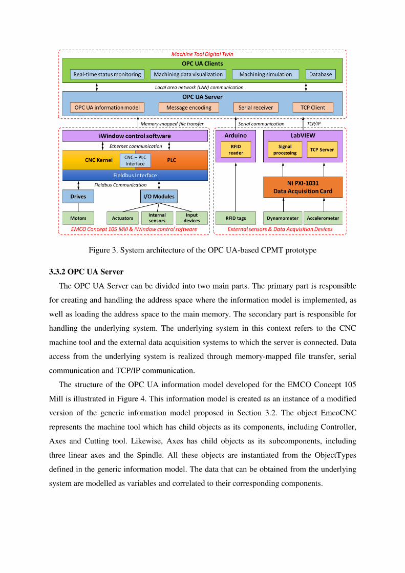
Figure 3. System architecture of the OPC UA-based CPMT prototype
3.3.2 OPC UA Server
The OPC UA Server can be divided into two main parts. The primary part is responsible
for creating and handling the address space where the information model is implemented, as
well as loading the address space to the main memory. The secondary part is responsible for
handling the underlying system. The underlying system in this context refers to the CNC
machine tool and the external data acquisition systems to which the server is connected. Data
access from the underlying system is realized through memory-mapped file transfer, serial
communication and TCP/IP communication.
The structure of the OPC UA information model developed for the EMCO Concept 105
Mill is illustrated in Figure 4. This information model is created as an instance of a modified
version of the generic information model proposed in Section 3.2. The object EmcoCNC
represents the machine tool which has child objects as its components, including Controller,
Axes and Cutting tool. Likewise, Axes has child objects as its subcomponents, including
three linear axes and the Spindle. All these objects are instantiated from the ObjectTypes
defined in the generic information model. The data that can be obtained from the underlying
system are modelled as variables and correlated to their corresponding components.
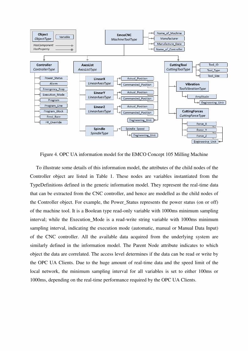
Figure 4. OPC UA information model for the EMCO Concept 105 Milling Machine
To illustrate some details of this information model, the attributes of the child nodes of the
Controller object are listed in Table 1. These nodes are variables instantiated from the
TypeDefinitions defined in the generic information model. They represent the real-time data
that can be extracted from the CNC controller, and hence are modelled as the child nodes of
the Controller object. For example, the Power_Status represents the power status (on or off)
of the machine tool. It is a Boolean type read-only variable with 1000ms minimum sampling
interval; while the Execution_Mode is a read-write string variable with 1000ms minimum
sampling interval, indicating the execution mode (automatic, manual or Manual Data Input)
of the CNC controller. All the available data acquired from the underlying system are
similarly defined in the information model. The Parent Node attribute indicates to which
object the data are correlated. The access level determines if the data can be read or write by
the OPC UA Clients. Due to the huge amount of real-time data and the speed limit of the
local network, the minimum sampling interval for all variables is set to either 100ms or
1000ms, depending on the real-time performance required by the OPC UA Clients.
Table 1. Nodes and attributes of Controller object
BrowseName Data Type Access Level
Minimum Sampling
Interval (ms) Parent Node
Power_Status Boolean Read 1000 ControllerType
Alarm String Read 100 ControllerType
Emergency_Stop Boolean Read-Write 100 ControllerType
Execution_Mode String Read-Write 1000 ControllerType
Program String Read-Write 1000 ControllerType
Program_Line Double Read 100 ControllerType
Program_Block String Read 100 ControllerType
Feedrate Double Read 100 ControllerType
FR_Override Double Read-Write 100 ControllerType
The Information model is an integral part of the OPC UA server and hence the hierarchical
representation shown in Figure 4 needs to be represented in its respective source codes. In our
case study we made use of an open source Information Model Compiler library that was
provided as a part of the repository on Github by the OPC Foundation. The Information
Model Compiler intakes an XML representation of the hierarchy and a comma separated
value (CSV) file which enlists all the ObjectTypes, Objects, Variables and Methods along
with an identifier value to every single component. The generated source code is then
integrated as a part of the OPC UA Server. Since the OPC UA Clients developed for this
prototype are mainly used in the local network, OPC UA Binary is used for the data encoding
in this Server. OPC UA Binary has smaller size and allows faster encoding and decoding
compared to XML, thus enabling more efficient data transmission between the OPC UA
Server and local OPC UA Clients.
The User Interface (UI) of the developed OPC UA Server is shown in Figure 5. The
Server endpoint URL is displayed as per it is defined in the XML server configuration file.
Once the OPC UA Client establishes a successful connection with the server, details of the
connection will be displayed in the Sessions module. This information can be used to identify
the current users who are accessing the server for real-time data access. Once the user creates
a subscription for a node on the OPC UA Client, the subscription details will be reflected in
the Subscriptions module. More details regarding the status and overall performance
information of the Server is shown at the bottom of the UI.
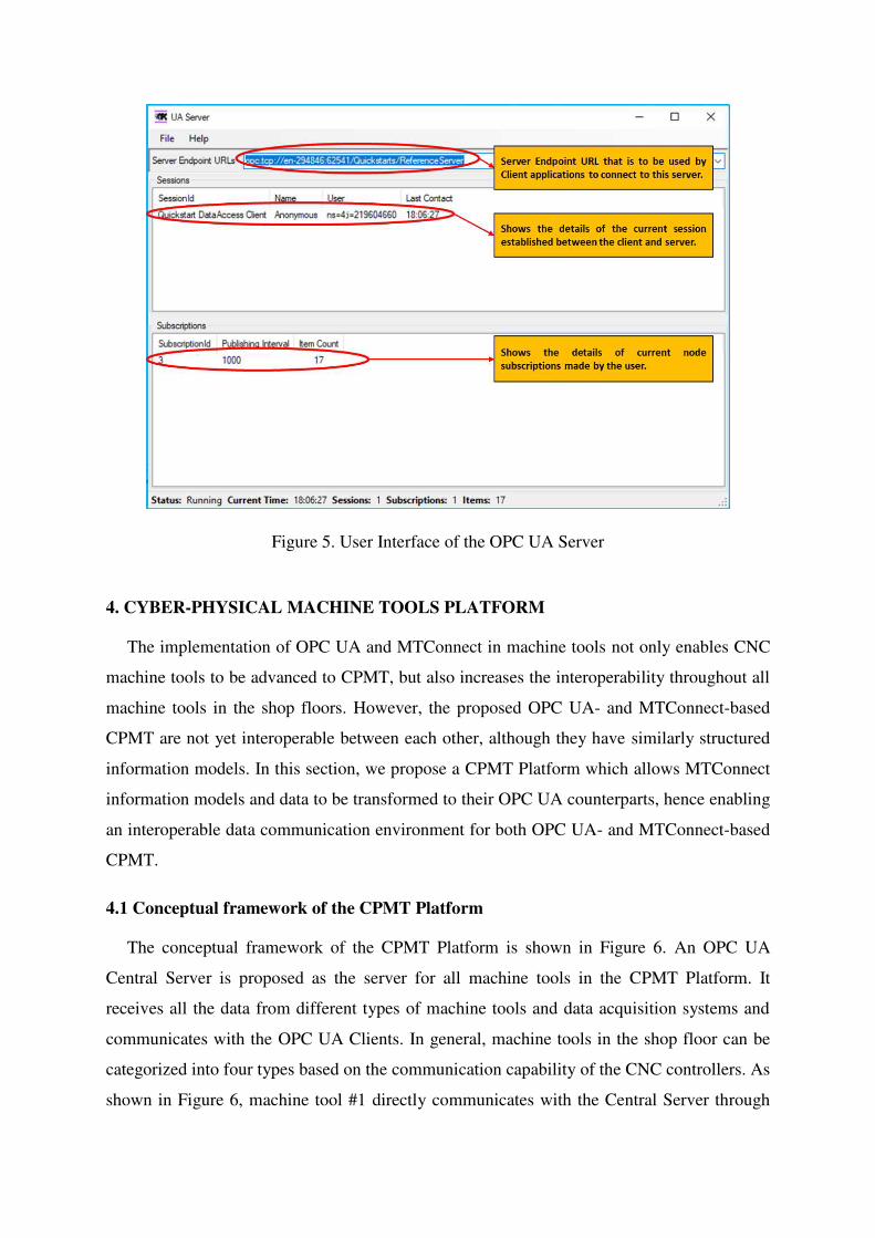
Figure 5. User Interface of the OPC UA Server
4. CYBER-PHYSICAL MACHINE TOOLS PLATFORM
The implementation of OPC UA and MTConnect in machine tools not only enables CNC
machine tools to be advanced to CPMT, but also increases the interoperability throughout all
machine tools in the shop floors. However, the proposed OPC UA- and MTConnect-based
CPMT are not yet interoperable between each other, although they have similarly structured
information models. In this section, we propose a CPMT Platform which allows MTConnect
information models and data to be transformed to their OPC UA counterparts, hence enabling
an interoperable data communication environment for both OPC UA- and MTConnect-based
CPMT.
4.1 Conceptual framework of the CPMT Platform
The conceptual framework of the CPMT Platform is shown in Figure 6. An OPC UA
Central Server is proposed as the server for all machine tools in the CPMT Platform. It
receives all the data from different types of machine tools and data acquisition systems and
communicates with the OPC UA Clients. In general, machine tools in the shop floor can be
categorized into four types based on the communication capability of the CNC controllers. As
shown in Figure 6, machine tool #1 directly communicates with the Central Server through
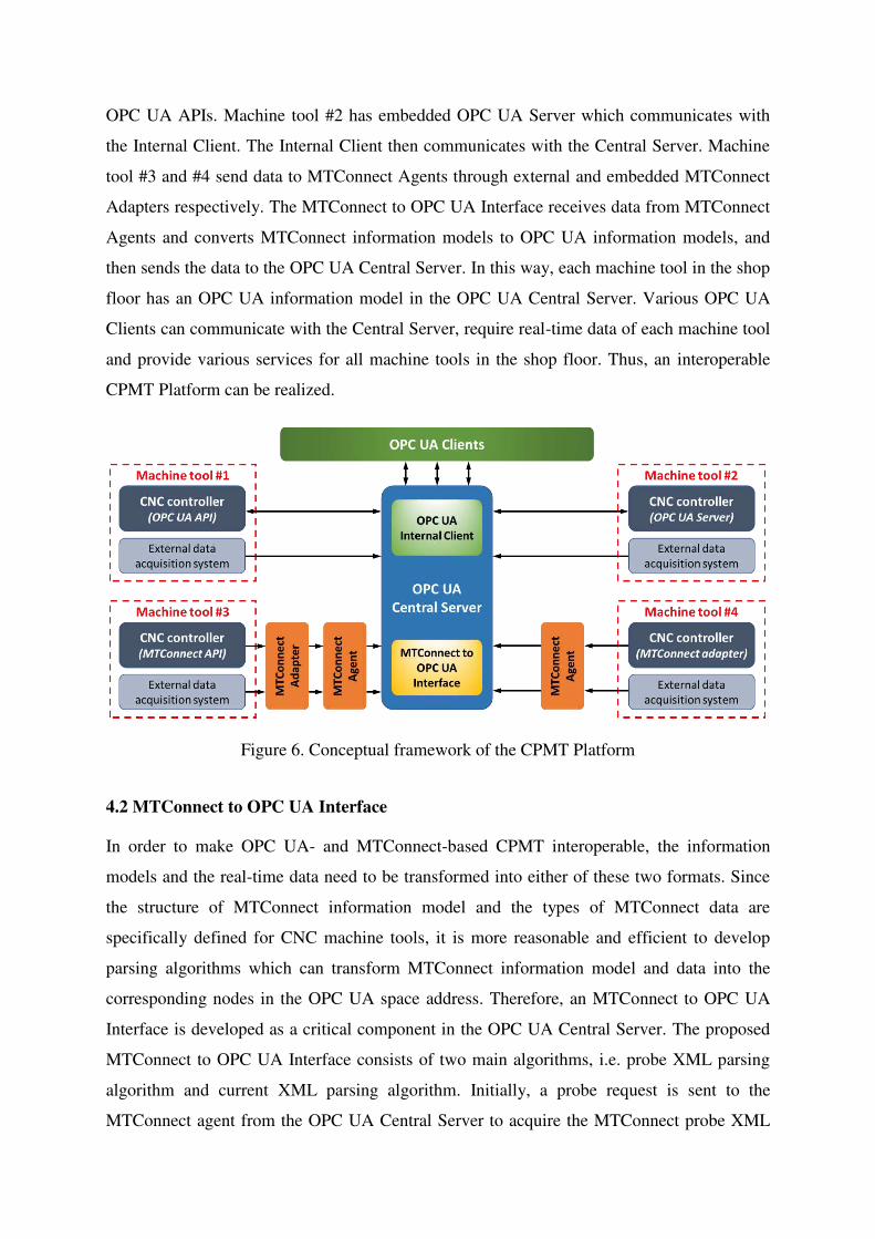
OPC UA APIs. Machine tool #2 has embedded OPC UA Server which communicates with
the Internal Client. The Internal Client then communicates with the Central Server. Machine
tool #3 and #4 send data to MTConnect Agents through external and embedded MTConnect
Adapters respectively. The MTConnect to OPC UA Interface receives data from MTConnect
Agents and converts MTConnect information models to OPC UA information models, and
then sends the data to the OPC UA Central Server. In this way, each machine tool in the shop
floor has an OPC UA information model in the OPC UA Central Server. Various OPC UA
Clients can communicate with the Central Server, require real-time data of each machine tool
and provide various services for all machine tools in the shop floor. Thus, an interoperable
CPMT Platform can be realized.
Figure 6. Conceptual framework of the CPMT Platform
4.2 MTConnect to OPC UA Interface
In order to make OPC UA- and MTConnect-based CPMT interoperable, the information
models and the real-time data need to be transformed into either of these two formats. Since
the structure of MTConnect information model and the types of MTConnect data are
specifically defined for CNC machine tools, it is more reasonable and efficient to develop
parsing algorithms which can transform MTConnect information model and data into the
corresponding nodes in the OPC UA space address. Therefore, an MTConnect to OPC UA
Interface is developed as a critical component in the OPC UA Central Server. The proposed
MTConnect to OPC UA Interface consists of two main algorithms, i.e. probe XML parsing
algorithm and current XML parsing algorithm. Initially, a probe request is sent to the
MTConnect agent from the OPC UA Central Server to acquire the MTConnect probe XML
file which includes information of all the available components and data items in the
MTConnect information model. Then the probe XML parsing algorithm parses the probe
XML file and aids the designer to create the corresponding OPC UA nodes in the OPC UA
Central Server. The specific mappings from the Structural Elements and Data Elements in
MTConnect information model to OPC UA nodes follow the mapping rules defined in the
MTConnect-OPC UA companion specification [50]. Thus, the OPC UA information model is
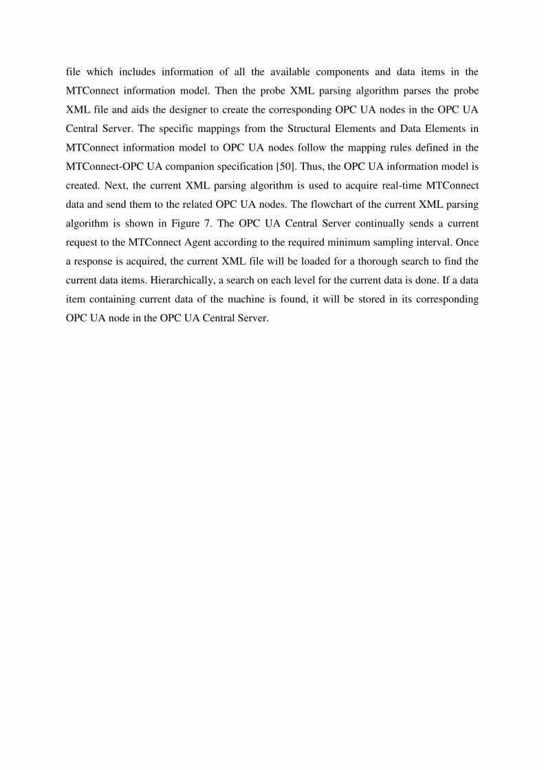
created. Next, the current XML parsing algorithm is used to acquire real-time MTConnect
data and send them to the related OPC UA nodes. The flowchart of the current XML parsing
algorithm is shown in Figure 7. The OPC UA Central Server continually sends a current
request to the MTConnect Agent according to the required minimum sampling interval. Once
a response is acquired, the current XML file will be loaded for a thorough search to find the
current data items. Hierarchically, a search on each level for the current data is done. If a data
item containing current data of the machine is found, it will be stored in its corresponding
OPC UA node in the OPC UA Central Server.
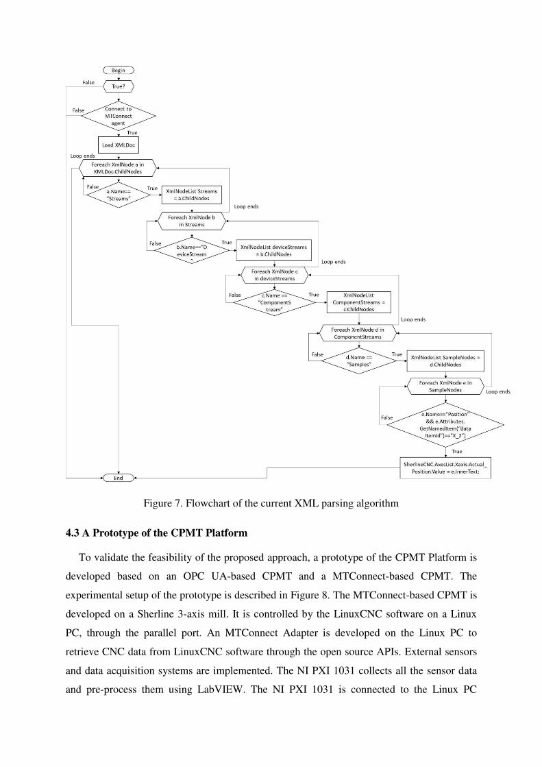
Figure 7. Flowchart of the current XML parsing algorithm
4.3 A Prototype of the CPMT Platform
To validate the feasibility of the proposed approach, a prototype of the CPMT Platform is
developed based on an OPC UA-based CPMT and a MTConnect-based CPMT. The
experimental setup of the prototype is described in Figure 8. The MTConnect-based CPMT is
developed on a Sherline 3-axis mill. It is controlled by the LinuxCNC software on a Linux
PC, through the parallel port. An MTConnect Adapter is developed on the Linux PC to
retrieve CNC data from LinuxCNC software through the open source APIs. External sensors
and data acquisition systems are implemented. The NI PXI 1031 collects all the sensor data
and pre-process them using LabVIEW. The NI PXI 1031 is connected to the Linux PC
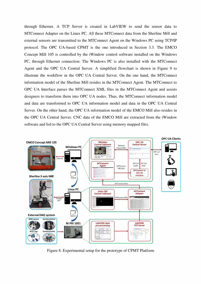
through Ethernet. A TCP Server is created in LabVIEW to send the sensor data to
MTConnect Adapter on the Linux PC. All these MTConnect data from the Sherline Mill and
external sensors are transmitted to the MTConnect Agent on the Windows PC using TCP/IP
protocol. The OPC UA-based CPMT is the one introduced in Section 3.3. The EMCO
Concept Mill 105 is controlled by the iWindow control software installed on the Windows
PC, through Ethernet connection. The Windows PC is also installed with the MTConnect
Agent and the OPC UA Central Server. A simplified flowchart is shown in Figure 9 to
illustrate the workflow in the OPC UA Central Server. On the one hand, the MTConnect
information model of the Sherline Mill resides in the MTConnect Agent. The MTConnect to
OPC UA Interface parses the MTConnect XML files in the MTConnect Agent and assists
designers to transform them into OPC UA nodes. Thus, the MTConnect information model
and data are transformed to OPC UA information model and data in the OPC UA Central
Server. On the other hand, the OPC UA information model of the EMCO Mill also resides in
the OPC UA Central Server. CNC data of the EMCO Mill are extracted from the iWindow
software and fed to the OPC UA Central Server using memory mapped files.
Figure 8. Experimental setup for the prototype of CPMT Platform
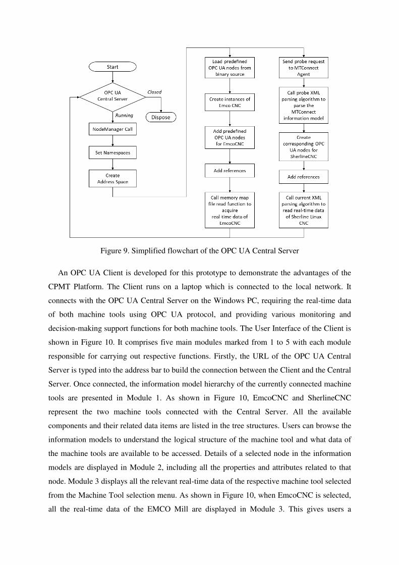
Figure 9. Simplified flowchart of the OPC UA Central Server
An OPC UA Client is developed for this prototype to demonstrate the advantages of the
CPMT Platform. The Client runs on a laptop which is connected to the local network. It
connects with the OPC UA Central Server on the Windows PC, requiring the real-time data
of both machine tools using OPC UA protocol, and providing various monitoring and
decision-making support functions for both machine tools. The User Interface of the Client is
shown in Figure 10. It comprises five main modules marked from 1 to 5 with each module
responsible for carrying out respective functions. Firstly, the URL of the OPC UA Central
Server is typed into the address bar to build the connection between the Client and the Central
Server. Once connected, the information model hierarchy of the currently connected machine
tools are presented in Module 1. As shown in Figure 10, EmcoCNC and SherlineCNC
represent the two machine tools connected with the Central Server. All the available
components and their related data items are listed in the tree structures. Users can browse the
information models to understand the logical structure of the machine tool and what data of
the machine tools are available to be accessed. Details of a selected node in the information
models are displayed in Module 2, including all the properties and attributes related to that
node. Module 3 displays all the relevant real-time data of the respective machine tool selected
from the Machine Tool selection menu. As shown in Figure 10, when EmcoCNC is selected,
all the real-time data of the EMCO Mill are displayed in Module 3. This gives users a
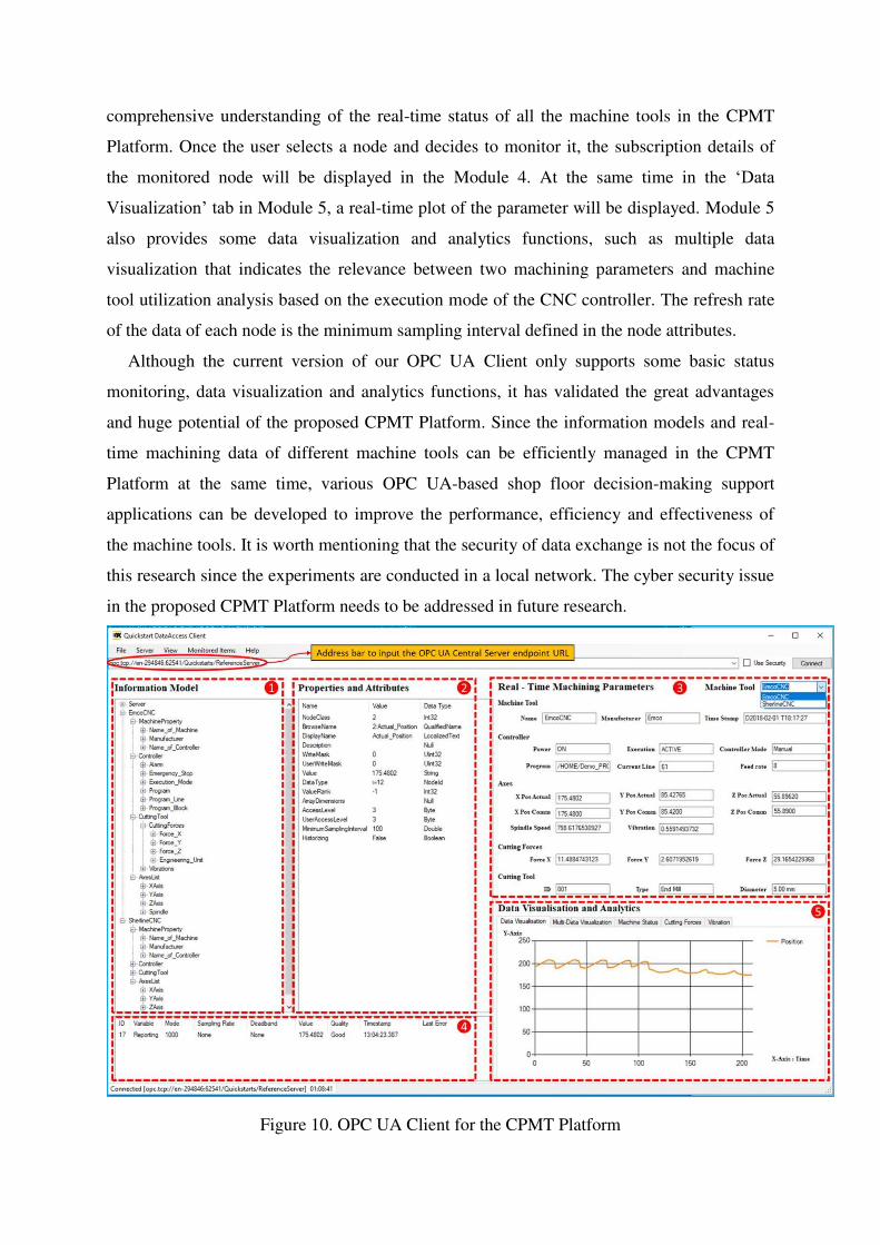
comprehensive understanding of the real-time status of all the machine tools in the CPMT
Platform. Once the user selects a node and decides to monitor it, the subscription details of
the monitored node will be displayed in the Module 4. At the same time in the ‘Data
Visualization’ tab in Module 5, a real-time plot of the parameter will be displayed. Module 5
also provides some data visualization and analytics functions, such as multiple data
visualization that indicates the relevance between two machining parameters and machine
tool utilization analysis based on the execution mode of the CNC controller. The refresh rate
of the data of each node is the minimum sampling interval defined in the node attributes.
Although the current version of our OPC UA Client only supports some basic status
monitoring, data visualization and analytics functions, it has validated the great advantages
and huge potential of the proposed CPMT Platform. Since the information models and real-
time machining data of different machine tools can be efficiently managed in the CPMT
Platform at the same time, various OPC UA-based shop floor decision-making support
applications can be developed to improve the performance, efficiency and effectiveness of
the machine tools. It is worth mentioning that the security of data exchange is not the focus of
this research since the experiments are conducted in a local network. The cyber security issue
in the proposed CPMT Platform needs to be addressed in future research.
Figure 10. OPC UA Client for the CPMT Platform
5. APPLICATIONS OF THE CPMT PLATFORM
This section briefly introduces two applications for the proposed CPMT Platform to
further demonstrate its advantages and potentials. The first application presents AR-assisted
machining process monitoring and simulation functions developed on a wearable device –
Microsoft HoloLens. This application demonstrates the advanced shop floor decision-making
supports enabled by the CPMT Platform. The second application, on the other hand,
introduces a conceptual framework for a CPMT powered cloud manufacturing environment
which enables dynamic information exchange between various cloud-based services and the
CPMT Platform.
5.1 AR-assisted process monitoring and simulation
Recent advancement in AR technology has shown great advantages in developing intuitive
HMIs for manufacturing facilities. The CPMT Platform allows all the available data of the
machine tools to be accessed in real time, thus providing a solid foundation for implementing
AR technology. In this application, AR is implemented in our CPMT Platform to develop an
intuitive HMI on a Microsoft HoloLens. This advanced HMI not only provides users with
intuitive perceptions of the real-time machining processes, but also supports high-fidelity
machining simulations based on the actual machining parameters.
The experimental environment and the workflow of this application is described in Figure
11. The HoloLens is connected to the host machine in the local network through WiFi. It
acquires real-time machining data of the EMCO Mill from the CPMT Platform Application.
The user “taps” the marker fixed on the machine tool to calibrate the positions of the virtual
objects (virtual workpiece, cutting tool, tool path and text information) to be overlaid. The
real-time axes positions acquired from the CPMT Platform Application are used for tracking
the movements of the cutting tool and the workpiece. On the one hand, when the user
wearing the HoloLens looks at the machine tool during machining processes, a
comprehensive and intuitive understanding of the machining process can be realized since the
real-time machine tool status, program information, cutting tool information, etc. are
displayed in real machining environment. The virtual cutting tool and tool path can also be
overlaid during machining, such that the visualization of the machining processes can be
enhanced when coolant or chips obstruct the process. On the other hand, the virtual
workpiece, virtual fixtures and virtual cutting tool can be overlaid on the worktable during a
dry run. In this situation, all the virtual objects are driven by the actual axes positions
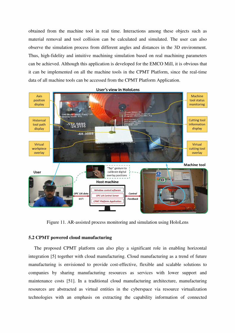
obtained from the machine tool in real time. Interactions among these objects such as
material removal and tool collision can be calculated and simulated. The user can also
observe the simulation process from different angles and distances in the 3D environment.
Thus, high-fidelity and intuitive machining simulation based on real machining parameters
can be achieved. Although this application is developed for the EMCO Mill, it is obvious that
it can be implemented on all the machine tools in the CPMT Platform, since the real-time
data of all machine tools can be accessed from the CPMT Platform Application.
Figure 11. AR-assisted process monitoring and simulation using HoloLens
5.2 CPMT powered cloud manufacturing
The proposed CPMT platform can also play a significant role in enabling horizontal
integration [5] together with cloud manufacturing. Cloud manufacturing as a trend of future
manufacturing is envisioned to provide cost-effective, flexible and scalable solutions to
companies by sharing manufacturing resources as services with lower support and
maintenance costs [51]. In a traditional cloud manufacturing architecture, manufacturing
resources are abstracted as virtual entities in the cyberspace via resource virtualization
technologies with an emphasis on extracting the capability information of connected
manufacturing resource [52,53]. These virtual manufacturing resources in the cloud are
encapsulated as on-demand manufacturing services that can be consumed on a pay-as-you-go
pricing model. A significant challenge in cloud manufacturing is that virtual resource
information is not always in sync with physical resource capability and availability
information. Therefore, service scheduling and resource coordination in the cloud cannot be
always guaranteed as optimal decisions due to a lack of understanding of dynamic machine
tool status.
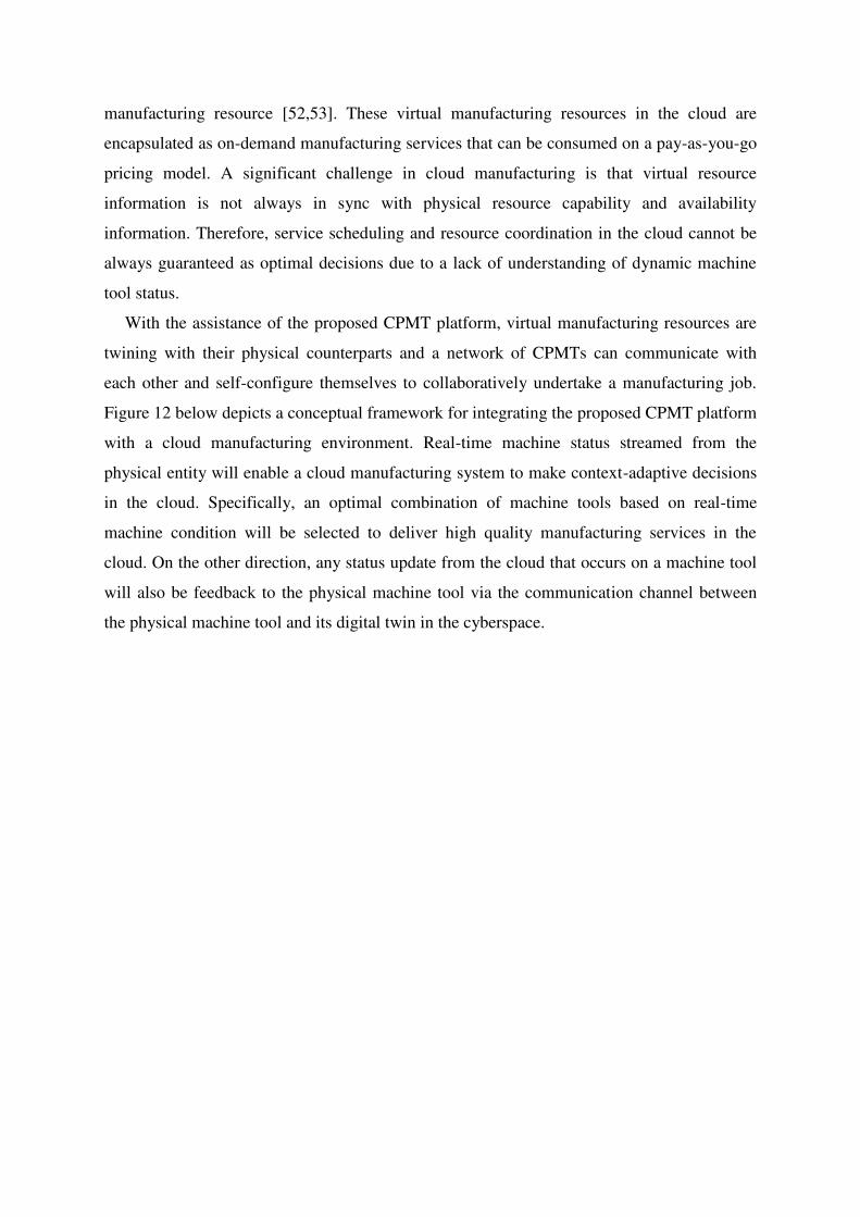
With the assistance of the proposed CPMT platform, virtual manufacturing resources are
twining with their physical counterparts and a network of CPMTs can communicate with
each other and self-configure themselves to collaboratively undertake a manufacturing job.
Figure 12 below depicts a conceptual framework for integrating the proposed CPMT platform
with a cloud manufacturing environment. Real-time machine status streamed from the
physical entity will enable a cloud manufacturing system to make context-adaptive decisions
in the cloud. Specifically, an optimal combination of machine tools based on real-time
machine condition will be selected to deliver high quality manufacturing services in the
cloud. On the other direction, any status update from the cloud that occurs on a machine tool
will also be feedback to the physical machine tool via the communication channel between
the physical machine tool and its digital twin in the cyberspace.
Figure 12. Conceptual framework for a CPMT powered cloud manufacturing environment
6. CONCLUSIONS
Industry 4.0 envisions the next generation of manufacturing systems as CPPS that
comprise various smart, autonomous, cooperative and interconnected manufacturing
facilities. Given the critical role machine tools play in any manufacturing systems, there
exists an urgent need to advance existing CNC machine tools to a higher level of
connectivity, accessibility, intelligence and autonomy, i.e. Machine Tool 4.0. Based on recent
advancements in ICT such as CPS, IoT and cloud technology, CPMT is considered as a
promising development trend for machine tools in the new era of Machine Tool 4.0. The core
of a CPMT lies in the digital twin of the machine tool, i.e. MTDT. Modelling of the MTDT is
a critical yet challenging task since it requires standardized information modelling method
and communication protocols for machine tools. OPC UA and MTConnect both provide
feasible solutions for this task.
Our previous work has proven the feasibility of developing an MTConnect-based CPMT.
Due to the lack of a systematic development method for OPC UA-based CPMT and the
interoperability issue between OPC UA and MTConnect, this paper proposes a CPMT
Platform to bridge the research gaps. The main contributions of this research are summarized
as follows. First, a development method for OPC UA-based CPMT is proposed based on a
generic OPC UA information model for CNC machine tools. An OPC UA-based CPMT
prototype is developed on an EMCO 3-axis milling machine to validate the feasibility.
Second, to address the issue of interoperability between OPC UA and MTConnect, an
MTConnect to OPC UA interface is developed to transform MTConnect information model
and data to their OPC UA counterparts. A CPMT Platform is established by connecting the
OPC UA-based CPMT prototype with a previously developed MTConnect-based CPMT.
Third, different applications are developed to demonstrate the advantages of the proposed
CPMT Platform, including an OPC UA Client, an advanced AR-assisted wearable HMI and a
conceptual framework for CPMT powered cloud manufacturing environment. Experimental
results have proven that the proposed CPMT platform can significantly improve the
interoperability and efficiency of data communication among machine tools and various
types of software applications, and hence enhancing the overall production efficiency and
effectiveness in the shop floor.
Recently, OPC UA and MTConnect are attracting more and more attention in both
industry and academia. With the rapid increase of OPC UA and MTConnect
implementations, more and more CNC machine tools in the shop floors can be advanced to
CPMT. The proposed CPMT Platform can thus enable an interoperable communication
environment for the envisioned CPPS and Smart Factory. It is noted that the development of
CPMT and CPMT platform is still at an early stage. The focus of future work in this area is
envisioned as the implementation of Artificial Intelligence in the CPMT platform. First,
advanced data analytics based on recent advancements of Machine Learning can be
implemented into the proposed CPMT platform to provide more intelligent decision-making
supports such as predictive maintenance. Second, direct feedback control loop from the
MTDT to the CNC needs to be developed to allow autonomous in-process machining
optimization. Furthermore, cooperation between the CPMT platform and other manufacturing
devices such as industrial robots and logistic systems needs to be investigated to establish the
envisioned CPPS and Smart Factory.
REFERENCES
[1] Monostori L. Cyber-physical production systems: Roots, expectations and R&D
challenges. Procedia CIRP, vol. 17, 2014, p. 9–13.
[2] Wang L, Törngren M, Onori M. Current Status and Advancement of Cyber - Physical
Systems in Manufacturing. Proceedings of the North American Manufacturing
Research 2015;.37:517–527.
[3] Zuehlke D. SmartFactory-Towards a factory-of-things. Annual Reviews in Control,
vol. 34, 2010, p. 129–38.
[4] Wang S, Wan J, Li D, Zhang C. Implementing Smart Factory of Industrie 4.0: An
Outlook. International Journal of Distributed Sensor Networks;2016.
[5] Kagermann H, Wahlster W, Helbig J. Securing the future of German manufacturing
industry: Recommendations for implementing the strategic initiative INDUSTRIE 4.0.
Final Report of the Industrie 40 Working Group 2013:1–84.
[6] Hermann M, Pentek T, Otto B. Design principles for industrie 4.0 scenarios.
Proceedings of the Annual Hawaii International Conference on System Sciences, vol.
2016–March, 2016, p. 3928–37.
[7] Xu X. Machine Tool 4.0 for the new era of manufacturing. International Journal of
Advanced Manufacturing Technology 2017;92:1893–900.
[8] Liu C, Xu X. Cyber-physical Machine Tool - The Era of Machine Tool 4.0. Procedia
CIRP, vol. 63, 2017, p. 70–5.
[9] Xu XW, Newman ST. Making CNC machine tools more open, interoperable and
intelligent—a review of the technologies. Computers in Industry 2006;57:141–52.
[10] Newman ST, Allen RD, Rosso RSU. CAD/CAM solutions for STEP-compliant CNC
manufacture. International Journal of Computer Integrated Manufacturing
2003;16:590–7.
[11] Lee EA. Cyber Physical Systems: Design Challenges. 2008 11th IEEE International
Symposium on Object and Component-Oriented Real-Time Distributed Computing
(ISORC), 2008, p. 363–9.
[12] MTConnect Institution. MTConnect 2008. http://www.mtconnect.org/ (accessed July
31, 2018).
[13] OPC Foundation. OPC Unified Architecture 2006.
https://opcfoundation.org/about/opc-technologies/opc-ua/ (accessed July 31, 2018).
[14] Liu C, Vengayil H, Zhong RY, Xu X. A systematic development method for cyber-
physical machine tools. Journal of Manufacturing Systems 2018; 48:13-24.
[15] Liu C, Xu X, Peng Q, Zhou Z. MTConnect-based Cyber-Physical Machine Tool: a
case study. Procedia CIRP 2018;72:492–7.
[16] Shafto M, Conroy M, Doyle R, Glaessgen E. DRAFT Modeling, Simulation,
information Technology & Processing Roadmap. Technology Area 2010.
[17] Negri E, Fumagalli L, Macchi M. A Review of the Roles of Digital Twin in CPS-based
Production Systems. Procedia Manufacturing 2017;11:939–48.
[18] Glaessgen E, Stargel D. The Digital Twin Paradigm for Future NASA and U.S. Air
Force Vehicles. 53rd AIAA/ASME/ASCE/AHS/ASC Structures, Structural Dynamics
and Materials Conference<BR>20th AIAA/ASME/AHS Adaptive Structures
Conference<BR>14th AIAA, 2012.
[19] Rosen R, Von Wichert G, Lo G, Bettenhausen KD. About the importance of autonomy
and digital twins for the future of manufacturing. IFAC-PapersOnLine, vol. 28, 2015,
p. 567–72.
[20] Tao F, Cheng J, Qi Q, Zhang M, Zhang H, Sui F. Digital twin-driven product design,
manufacturing and service with big data. The International Journal of Advanced
Manufacturing Technology 2017. 94(9-12):3563-76
[21] Schleich B, Anwer N, Mathieu L, Wartzack S. Shaping the digital twin for design and
production engineering. CIRP Annals - Manufacturing Technology 2017;66:141–4.
[22] Lee J, Bagheri B, Kao HA. A Cyber-Physical Systems architecture for Industry 4.0-
based manufacturing systems. Manufacturing Letters 2015;3:18–23.
[23] Tao F, Zhang M, Liu Y, Nee AYC. Digital twin driven prognostics and health
management for complex equipment. CIRP Annals 2018;67(1):169-72.
[24] Cai Y, Starly B, Cohen P, Lee YS. Sensor Data and Information Fusion to Construct
Digital-twins Virtual Machine Tools for Cyber-physical Manufacturing. Procedia
Manufacturing 2017;10:1031–42.
[25] Schroeder GN, Steinmetz C, Pereira CE, Espindola DB. Digital Twin Data Modeling
with AutomationML and a Communication Methodology for Data Exchange. IFAC-
PapersOnLine 2016;49:12–7.
[26] Urbina Coronado PD, Lynn R, Louhichi W, Parto M, Wescoat E, Kurfess T. Part data
integration in the Shop Floor Digital Twin: Mobile and cloud technologies to enable a
manufacturing execution system. Journal of Manufacturing Systems 2018;48:25-33.
[27] STEP Tools Inc. Digital Thread for Manufacturing 2017.
https://www.steptools.com/sln/thread/.
[28] VDI/VDE. Reference Architecture Model Industrie 4.0 (RAMI4.0). Igarss 2014
2015;0:28.
[29] Schleipen M, Gilani SS, Bischoff T, Pfrommer J. OPC UA & Industrie 4.0 - Enabling
Technology with High Diversity and Variability. Procedia CIRP, vol. 57, 2016, p.
315–20.
[30] Schlechtendahl J, Keinert M, Kretschmer F, Lechler A, Verl A. Making existing
production systems Industry 4.0-ready: Holistic approach to the integration of existing
production systems in Industry 4.0 environments. Production Engineering 2014;9:143–8.
[31] Garcia M V., Irisarri E, Pérez F, Estevez E, Marcos M. OPC-UA communications
integration using a CPPS architecture. 2016 IEEE Ecuador Technical Chapters
Meeting, ETCM 2016.
[32] Muller M, Wings E, Bergmann L. Developing open source cyber-physical systems for
service-oriented architectures using OPC UA. 2017 IEEE 15th International
Conference on Industrial Informatics (INDIN) 2017:83–8.
[33] Imtiaz J, Jasperneite J. Scalability of OPC-UA down to the chip level enables “internet of Things.” IEEE International Conference on Industrial Informatics (INDIN), 2013, p. 500–5.
[34] Luo Z, Hong S, Lu R, Li Y, Zhang X, Kim J, et al. OPC UA-Based Smart
Manufacturing: System Architecture, Implementation, and Execution. Proceedings -
2017 5th International Conference on Enterprise Systems: Industrial Digitalization by
Enterprise Systems, ES 2017, 2017, p. 281–6.
[35] Wu D, Liu S, Zhang L, Terpenny J, Gao RX, Kurfess T, et al. A fog computing-based
framework for process monitoring and prognosis in cyber-manufacturing. Journal of
Manufacturing Systems 2017;43:25-34.
[36] Ayatollahi I, Kittl B, Pauker F, Martin H. Prototype OPC UA Server for Remote
Control of Machine Tools. International Conference on Innovative Technologies, vol.
1009, 2013, p. 73–6.
[37] Pauker F, Ayatollahi I, Kittl B. Service Orchestration for Flexible Manufacturing
Systems using Sequential Functional Charts and OPC UA. International Conference on
Innovative Technologies (IN-TECH) 2015:9–12.
[38] Abele E, Panten N, Menz B. Data collection for energy monitoring purposes and
energy control of production machines. Procedia CIRP, vol. 29, 2015, p. 299–304.
[39] Faltinski S, Flatt H, Pethig F, Kroll B, Vodenčarević A, Maier A, et al. Detecting anomalous energy consumptions in distributed manufacturing systems. IEEE
International Conference on Industrial Informatics (INDIN), 2012, p. 358–63.
[40] Di Orio G, C??ndido G, Barata J, Bittencourt JL, Bonefeld R. Energy efficiency in
machine tools - A self-learning approach. Proceedings - 2013 IEEE International
Conference on Systems, Man, and Cybernetics, SMC 2013, 2013, p. 4878–83.
[41] Pauker F, Frühwirth T, Kittl B, Kastner W. A Systematic Approach to OPC UA
Information Model Design. Procedia CIRP, vol. 57, 2016, p. 321–6.
[42] Girbea A, Nechifor S, Sisak F, Perniu L. Efficient address space generation for an
OPC UA server. Software - Practice and Experience 2012;42:543–57.
[43] Claassen A, Rohjans S, Lehnhoff Member S. Application of the OPC UA for the
Smart Grid. IEEE PES Innovative Smart Grid Technologies Conference Europe, 2011.
[44] Zawawi A El, El-Sayed A. Integration of DCS and ESD through an OPC application
for upstream Oil and Gas. IEEE Power and Energy Society General Meeting, 2012.
[45] Maka A, Cupek R, Rosner J. OPC UA object oriented model for public transportation
system. Proceedings - UKSim 5th European Modelling Symposium on Computer
Modelling and Simulation, EMS 2011.
[46] Siemens AG. OPC UA Server for SINUMERIK 828D and SINUMERIK 840D sl
2017. https://support.industry.siemens.com.
[47] VDW and OPC Foundation. OPC-UA Information Model for CNC Systems -
Companion Specification Release 1.0 2017. https://opcfoundation.org/developer-
tools/specifications-unified-architecture/opc-unified-architecture-for-cnc-systems/.
[48] Sobel W. MTConnect ® Standard Part 2 – Device Information Model 2014.
[49] Liu C, Cao S, Tse W, Xu X. Augmented Reality-assisted Intelligent Window for
Cyber-Physical Machine Tools. Journal of Manufacturing Systems 2017;44:280–6.
[50] OPC Foundation and MTConnect Institute. MTConnect-OPC UA Companion
Specification. Version 1.02, Release Candidate 2013. http://www.mtconnect.org/opc-
ua-companion-specification (accessed July 31, 2018).
[51] Li BH. b, Zhang L., Wang SL., Tao F., Cao JW., Jiang XD., Song X, Chai XD. Cloud
manufacturing: A new service-oriented networked manufacturing model. Computer
Integrated Manufacturing Systems, 2010;16(1):1–7.
[52] Xu X. From cloud computing to cloud manufacturing. Robotics and Computer-
Integrated Manufacturing 2012;28:75–86.
[53] Lu Y, Xu X, Xu J. Development of a Hybrid Manufacturing Cloud. Journal of
Manufacturing Systems 2014;33:551–66.