Embed Size (px)
Citation preview

A Custom IR Scanner for Landmark Detection with the Autonomous SewerRobot MAKRO
Erich Rome, Hartmut Surmann, Hermann Streich, Ulrich Licht, and Karl-Ludwig Paap
GMD – NationalResearchCenterfor InformationTechnologyInstitutefor AutonomousintelligentSystems� firstname� . � lastname� @gmd.de,http://ais.gmd.de/projects/Makro/makro.html
9th International Symposiumon Intelligent RoboticSystems,SIRS2001,Toulouse, France, ed. Michel Devy and FredericLerasle, pub. LAAS-CNRS,ISBN2-907801-01-5,pp.457-466,18-20July 2001.
Abstract. MAKRO is anautonomoussewer robotdesignedfor navigating in sewer pipes.In orderto find its way to a specifiedgoal manhole,it hasto solve the self-localizationproblem.The sewer environmentcontainsonly few featuresthat are usableaslandmarksfor re-localization,namelyinlets,pipe joints andbranchingpipes.This paperdescribeshow a custom2D scannerinvolving infrareddistancesensorswith high samplingratescanbe employed for robust andfastdetectionof inlets. Up to 150measurementspersecondarepreprocessedon a microcontroller, detectionresultsarepassedto higherlevel controlprogramson afasterCPU.Thesystemrequiresonly a brief initial automaticcalibration.It is smallerandcheaperthancomparablesensors,it isfastandit requireslesson-boardresourcesin termsof computingtime,energy, andspace.
1 The Autonomous Sewer Robot MAKRO
MAKRO is a prototypeof anautonomousmobilerobotplatformdesignedfor navigatingin inaccessiblesewer pipes.It is able to drive autonomouslyin sewer pipesof diametersbetween300 and600mm, steeredby navigation andmotioncontrolroutinesrunningon a PC/104CPU,relyingonly on sewer mapsandon datafrom numerouson-boardsensors.
Sucha platform cancarry variousapplicationsfor sewer maintenance,like devices for measuringthe physicaldimensionsof sewers,sensorsfor detectingchemicalsewagepollution, andmore.This could help to make sewermaintenancefaster, better, andcheaper, enablingcommunitiesto inspector measuretheir sewer systems(cf. Ency-clopediaBritannica(2001))moreoften,aswill be prescribedby forthcomingEuropeanlegislation.A rationaleforautonomoussewer robotsis describedin (Romeet al., 1999).
MAKRO differs from conventionalinspectionequipmentin main aspects:A conventionalinspection“robot” istied to a cablethatconnectsit to a surveillanceunit. Thecableprovidessupplyenergy, teleoperationcontrolsignals,andvideosignals,but it alsolimits theoperationrange.MAKRO, on theotherhand,is unleashedandcarriesall theresourcesit needson-board.MAKRO is an articulaterobot consistingof six segments,connectedwith five activejoints (cf. fig. 1(a)).Eachjoint is drivenby threemotors,enablingMAKRO to bendandlift partsof its 50 kilogrambodyfor climbing andturningmaneuvres.Thesix drivenwheelaxesandthefifteen joint motorsaddup to a total of21 degreesof freedomfor MAKRO 1.1 thathave to becontrolled.Conventionalinspectionequipmenthasonly onelargerigid bodysegmentthatpreventsturningandclimbingmaneuvres.
MAKRO alsoincorporatesanumberof internalsensors.A thermometerfor measuringtheCPUtemperature,pulsecountersfor odometry, opticalsensorsfor readingjoint angleencodings,andmore.Sensorsfor dataacquisitionfromtheenvironmentaremainly locatedin bothidenticallyequippedheadsegments.Eachof themcontainsastereocamerapair, lighting equipment,anultrasoundtransducerfor obstacledetection,four fixedinfrareddistancetransducers,andthecustomIR scannerwhich this articleis about.
The MAKRO prototypeis designedto operatein roughly cleanedsewers at dry weatherconditions.Its hous-ing is waterproof,andmodestlyresistantto corrosive substances.Someoptical sensorsareprotectedwith speciallycoatedglassthat rejectsdirt andwater (cf. (Kepplin et al., 1999;Scholl et al., 1999) for moredetailson the robotconstruction).
MAKRO’skinematicsenablesit to performturnsatsewerpipejunctionsandto climbstepsupto aheightof 35 cm.Thesenew capabilitiesallow for moreflexible maneuvresandlongermissions,sincethe robot doesnot have to bemanuallyput into a branchingpipeor into a pipesectionbehinda step.Figure1(b) showsMAKRO 1.0performingaturn in adry testsewer. Basically, thedurationof MAKRO’smissionsis only limited by theon-boardbatterycapacity.Duringourexperiments,we achievedoperationtimesof up to two hourswith onebatterycharge.
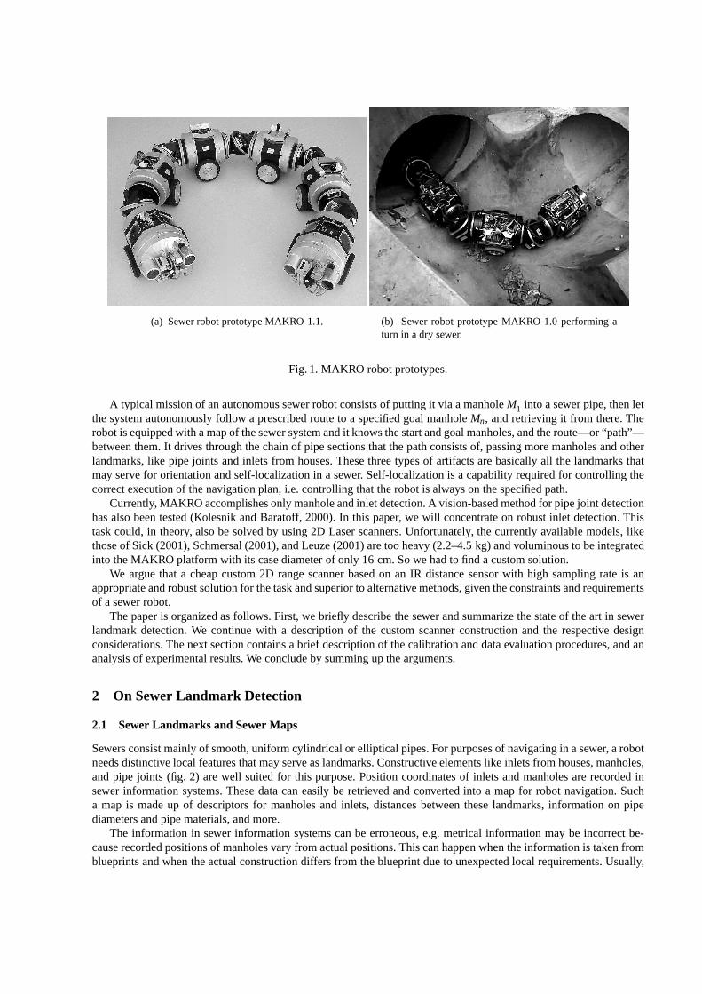
(a) Sewer robotprototypeMAKRO 1.1. (b) Sewer robot prototypeMAKRO 1.0 performingaturn in a dry sewer.
Fig.1. MAKRO robotprototypes.
A typicalmissionof anautonomoussewer robotconsistsof puttingit via amanholeM1 into asewerpipe,thenletthesystemautonomouslyfollow a prescribedrouteto a specifiedgoalmanholeMn, andretrieving it from there.Therobotis equippedwith amapof thesewersystemandit knowsthestartandgoalmanholes,andtheroute—or“path”—betweenthem.It drivesthroughthechainof pipesectionsthatthepathconsistsof, passingmoremanholesandotherlandmarks,like pipe joints andinlets from houses.Thesethreetypesof artifactsarebasicallyall the landmarksthatmayserve for orientationandself-localizationin a sewer. Self-localizationis a capabilityrequiredfor controllingthecorrectexecutionof thenavigationplan,i.e. controllingthattherobotis alwayson thespecifiedpath.
Currently, MAKROaccomplishesonly manholeandinlet detection.A vision-basedmethodfor pipejoint detectionhasalsobeentested(KolesnikandBaratoff, 2000).In this paper, we will concentrateon robust inlet detection.Thistaskcould, in theory, alsobe solvedby using2D Laserscanners.Unfortunately, thecurrentlyavailablemodels,likethoseof Sick (2001),Schmersal(2001),andLeuze(2001)aretooheavy (2.2–4.5kg) andvoluminousto beintegratedinto theMAKRO platformwith its casediameterof only 16 cm.Sowe hadto find acustomsolution.
We arguethat a cheapcustom2D rangescannerbasedon an IR distancesensorwith high samplingrate is anappropriateandrobustsolutionfor thetaskandsuperiorto alternativemethods,giventheconstraintsandrequirementsof asewer robot.
Thepaperis organizedasfollows.First,we briefly describethesewer andsummarizethestateof theart in sewerlandmarkdetection.We continuewith a descriptionof the customscannerconstructionand the respective designconsiderations.Thenext sectioncontainsa brief descriptionof thecalibrationanddataevaluationprocedures,andananalysisof experimentalresults.We concludeby summingup thearguments.
2 On Sewer Landmark Detection
2.1 Sewer Landmarks and Sewer Maps
Sewersconsistmainlyof smooth,uniformcylindrical or elliptical pipes.For purposesof navigatingin asewer, arobotneedsdistinctive local featuresthatmayserveaslandmarks.Constructiveelementslike inletsfrom houses,manholes,andpipe joints (fig. 2) arewell suitedfor this purpose.Positioncoordinatesof inlets andmanholesarerecordedinsewer informationsystems.Thesedatacaneasilybe retrieved andconvertedinto a mapfor robot navigation.Sucha map is madeup of descriptorsfor manholesand inlets, distancesbetweentheselandmarks,informationon pipediametersandpipematerials,andmore.
The informationin sewer informationsystemscanbe erroneous,e.g.metrical informationmay be incorrectbe-causerecordedpositionsof manholesvary from actualpositions.Thiscanhappenwhentheinformationis takenfromblueprintsandwhentheactualconstructiondiffersfrom theblueprintdueto unexpectedlocal requirements.Usually,

Fig.2. Imagesof aninlet, pipejoints,anda manholetakenwith MAKRO’scameras.
the blueprintsarenot updatedin suchcases.Also, theremay be illegal inlets which arenot recordedin a sewer in-formationsystem.This meansthatmapinformationis uncertainto somedegree,andthat an autonomousrobot hasto copewith this type of uncertainty. Navigation underuncertaintyis ongoingresearch(Gasos andSaffiotti (1999);Moonet al. (1999))andbeyondthescopeof this article.
2.2 State of the Art in Sewer Landmark Detection
Thedetectionof sewer landmarksfor self-localizationpurposeshasalreadybeenapproachedusingdifferentmethods.First navigationexperimentswith sewer robottestplatformshavebeenconductedin a dry sewer testnetat theGMDsitein SanktAugustin(Hertzberg andKirchner,1996).Figure3 shows thenetanda graphicalmapof it. Themethodfor navigationunderuncertaintyof sensorinformationdescribedin (Hertzberg andKirchner,1996)employedonly atopologicalmapof thetestnet,consistingof agraphandmanholeshapeinformation(L-, T-, X-shaped).Thepresenceof a manholecouldbedetectedby ultrasoundsensordataevaluation.Themanholewasthenscannedby a different,pivotedultrasoundtransducer. Themanholeshapecouldbeclassifiedfrom thescandataby aspeciallytrainedartificialneuralnetwork. Although it hasa high rateof correctclassifications(75 out of 81 samples),this methodlacksthecapabilityof identifying individualmanholes.
S1
S2
S3
S4
S5
S6
S7
S8
S9
S11
S10
Fig.3. Dry sewer testnet,correspondingmap.
For a more fine-grainedlocalization,the methodhasbeenfurther enhancedby inlet detectionusing a secondpivotedultrasoundtransducerSchonherret al. (1999) that permanentlyscansthe walls of upperhalf pipe sections.This procedureis time consumingandrequiresa speedmaximumthat lies clearly below the recommendedsewerinspectionspeedmaximumof 20 cm/s.
Palettaet al. (1999)describeexperimentswith a methodfor discoveringinlets in grayscaleimagestakenwith anonboardCCD camera.The methodinvolvesa time consumingtraining phase,whereasdetectionof trainedinlets isratherfast.In realsewers,therobotwouldneedto exploreunknown sewersectionsin orderto performthemandatorytrainingphase.This procedureis notdesirablein practice.
Campbellet al. (1995)andClarke(1995),usedifferentpipeprofiling methodsfor 3D reconstructionof sewerpipesin order to automaticallydetectdamages.The sensordevicesaremountedon teleoperatedsewer robot equipment,andthe dataevaluationis performedby a stationarycomputerin a surveillancevehicle.In principle, theseprofilingmethodsarealsosuitedfor inlet detection.But therequiredhardwareequipmentof Campbell’s (1995)PIRAT systemandClarke’s (1995)profiling instrumentaretoo largeandheavy to beintegratedinto thecaseof a smallautonomousmobilerobot.
KuntzeandHaffner (1998)describea device combiningstructuredlight projectorsandcamerasfor sewer pipeprofiling with theteleoperatedKARO robot.KARO hasasimilarly smallheadasMAKRO, but thedeviceleaveslittlespacefor theothersensorsthatMAKRO needsfor autonomousnavigation(cf. figuresin section3).
Alternatively, we proposeto scanpipewall sectionsfor inletsusinga cheapcustominfrareddistancesensorwithahigh samplingfrequency.
3 A Custom IR Scanner for Landmark Detection
3.1 Sensor Construction
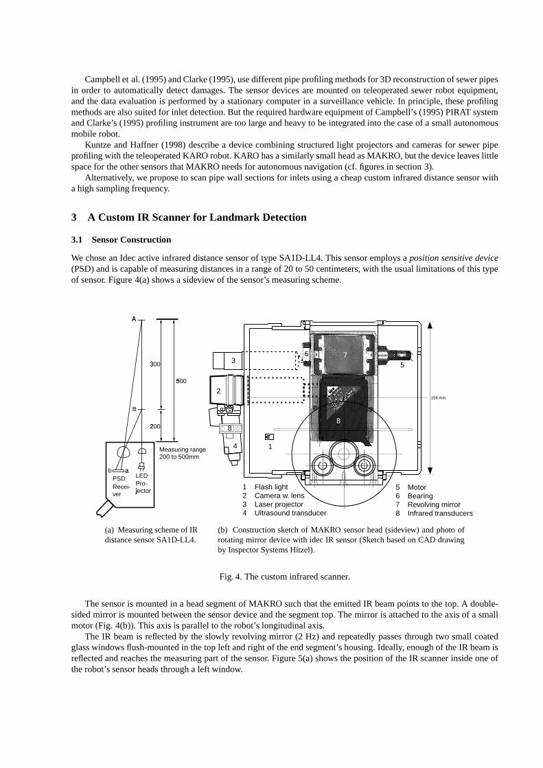
We choseanIdecactive infrareddistancesensorof typeSA1D-LL4. This sensoremploys a positionsensitivedevice(PSD)andis capableof measuringdistancesin a rangeof 20 to 50 centimeters,with theusuallimitationsof this typeof sensor. Figure4(a)showsa sideview of thesensor’smeasuringscheme.
Measuring range 200 to 500mm
Pro- j�ector
Recei- ver
LED
A�
B
5�
00
3�
00
2�
00
a�bPSD
(a) Measuringschemeof IRdistancesensorSA1D-LL4.
158 mm
5 Motor 6 Bearing 7 Revolving mirror 8 Infrared transducers
1 Flash light 2 Camera w. lens 3 Laser projector 4 Ultrasound transducer
1
2
3
4
5
6 7
8
88
(b) Constructionsketchof MAKRO sensorhead(sideview) andphotoofrotatingmirror device with idec IR sensor(Sketchbasedon CAD drawingby InspectorSystemsHitzel).
Fig.4. Thecustominfraredscanner.
Thesensoris mountedin a headsegmentof MAKRO suchthat theemittedIR beampointsto thetop.A double-sidedmirror is mountedbetweenthesensordevice andthesegmenttop.Themirror is attachedto theaxisof a smallmotor(Fig. 4(b)).This axisis parallelto therobot’s longitudinalaxis.
The IR beamis reflectedby the slowly revolving mirror (2 Hz) andrepeatedlypassesthroughtwo small coatedglasswindowsflush-mountedin thetop left andright of theendsegment’shousing.Ideally, enoughof theIR beamisreflectedandreachesthemeasuringpartof thesensor. Figure5(a)shows thepositionof theIR scannerinsideoneoftherobot’ssensorheadsthrougha left window.

(a) Frontsegmentof MAKRO 1.1with sensors.TheidecIR sensoris visible throughthewindow.
Rotating mirror
Left windowRight window
IR distance sensor
Pipe (300 mm) Reed contact
45° 45°
(b) Schematicfront view of scanningrangeforinlet detection(Sketchbasedon CAD drawingby InspectorSystemsHitzel).
Fig.5. Scanwindowsandscanrange.
Sewer inletsarenot equallydistributedalongthepipeperimeter. Rather, they appearin certainknown locations,namelyin thetop left andright of pipes.This allows usto restrictthesearcharea(grey regionsin figure5(b)) andtodesignthesizeandpositionof thewindowsasdescribed.Thesmallwindow sizealsocontributesto thestabilityof therobotcase.
3.2 Data Selection
Thesensorarrangementdescribedin theprevioussubsectionmakesthepermanentlyrotatingmirror reflectmostof theIR beamsinto theheadsegmentcase.Thuswehadto distinguishpotentiallyusefuldatawhichcomefrom outsidetherobot from uselessdatafrom theinterior. We attacheda tiny permanentmagnetto themirror carrier. A Reedcontactis placedsuchthatit fireswhenthemirror is in a verticalposition.This servesasa referencepoint.TheReedcontactanda specialcircuit disablethesensor’s dataoutputline for a shorttime, producinga zerovaluethatcanclearlybedistinguishedfrom measuredrealdata.
Approximatelyonly onefourthof all datahaveto beinterpreted,namelythosethatcomefrom therobot’sexterior.A typical dataseriesfor a second,i.e. two full rotationswheretheIR beampassesbothwindows eight times—sincethe mirror is double-sided—isshown in figure6. For a given scannermountedin a given endsegment,we have tocalibratethe interpretationroutinesin order to filter out uselessdatathat stemfrom refelectionswithin the robot’scase.This is describedin thenext section.
3.3 Scanning Frequency Considerations
Onepreconditionfor detectinginlets reliably is that the scanrastermustbe sufficiently densefor all pipe diame-tersbetween300 and600 millimeters.If possible,no inlet shall be overlookedwhile the robot travels at speedsupto 20 cm/s.An ultrasoundbasedscanneris inherentlytoo slow for this task,asa respective investigationrevealed(Schonherr,1998).
Typical inlet sizesrangebetween10 and 15 cm. To detectsuchan inlet, the distancesbetweenthe centersofsuccessive IR beamsshouldnot be larger than5 cm, peripherallyaswell as horizontally. The largestpipesunderconsideration,with a diameterof 600mm,haveperimetersof approximately185cm.Thus,37 measurementssufficeto achievetheperipheralbeamcenterdistanceof 5 cm for this classof pipes.For 300mm pipes,thesamenumberofmeasurementsyieldsanarrowerraster, wheretheperipheraldistanceis 2.5 cm.Thetypicaldiameterof abeamrangesfrom 14 mm at adistanceof 30 cmto 20 mm at a distanceof 50 cm.

0�
200
400
600
1000
2300 2350 2400 2450 2500
12 B
it A
/D
P
oint number
12 Bit A/D values in the sewerm irror position (index)
800
w� indowst�rue zero e rror
state: in sewer (40 cm)
Fig.6. Scannermeasurementsduringtwo full mirror rotations.Error peakgeneratedby in-robotreflection.Detectionstateis “in sewerpipe”.
In order to fully exploit the sensor’s capacityof up to 150 measurementsper second,the double-sidedmirrormay rotatewith 2 Hertz,yielding four completescanspersecond.Thus,the horizontalbeamcenterdistancecanbelimited to 5 cm simply by limiting the robot’s speedto the typical sewer inspectionspeedmaximumof 20 cm/s(=scanfrequency timesdesireddistance).
3.4 Data Processing Architecture
MAKROis steeredbyahighlevelcontrolprogramthatrunsonafull featuredPC/104operatedunderRealTimeLinux.ThePC/104communicatesvia CAN buswith sevenC167microcontrollers.Thelatteronescontrolthepropulsionandjoint motorsandreadthedataof mostof theinternalandexternalsensors(26 IR distancetransducers,two ultrasoundtransducers,a thermometer, two inclinometers,15 opticaljoint anglereaders,andmore(cf. (Kepplinet al., 1999)foradescriptionof MAKRO’smechatronicconcept).
Sensorreadingsthatarerelevant for high level controlprogramsaretransferredvia theCAN bus to thePC/104.Othersensordatamay be processedlocally on the C167microcontrollers.The C167is fastenoughto processthe150readingsof theIdecSA1D-LL4 while performingothercontrol tasks.A speciallycalibratedevaluationprogramdecideswhetherthe dataindicatethat an inlet hasbeenscanned.The resultsare passedto the high level controlprogramson thePC/104.
4 Algorithms and Experimental Results
4.1 Auto-Calibration Procedure
As mentionedin previoussection,theIR scannerhasto becalibrated.In half a second,therotatingmirror turns360degreesbetweentwo triggersof the Reedcontactandsweepsalongthe two windows. In the linear streamof datarecordedduringthathalf second,four interestingregionshaveto bedetected,namelythe“positions”of thewindows.
For performingthe calibrationprocess,the robot is moved outsidea sewer pipe suchthat the scannerdetectsno obstaclesandshows the maximumdistance.Figure7 shows a typical distribution of datacollectedduring a fullrotationwhile therobot is outsideof a pipe.Theramp-like spikesat theabscissaaregraphicalrepresentationsof thedataindices(cf. below).
In thesituationdescribedabove,all datameasuredin a periodof five seconds,i.e. during10 full mirror rotations,arerecordedandtransformedinto a histogram.During therecordingprocedure,anindex variablei is initialized with0 whentheReedcontactis closed,and i is increasedwhena new measurementarrives.For every measurementit ischeckedif thedigital valueliesin theintervalof � 100: 1000� and,if so,thehistogramvalueatpositioni is increasedby

0
200
4�
00
600
800
1000
2220 2240 2260 2280 2300 2320 2340
12 B
it A
/D
P�
oint number
m� irror position (index)12 Bit A/D values in the sewer
Fig.7. Measuredrangeswhile robotis outsideof apipe.
one.A typical histogramof thedistribution of thesemeasurementsis shown in figure8. Consequently, thepositionsof thefour largestlocal maximaareselectedandthe interestingregion areadjustedat � 7 index positionsaroundthelocal maxima(the number � 7 hasbeendeterminedempirically in our experiments).The obtainedintervals, i.e. theregionsof interest,arethenbeingusedto selectively filter out uselessdatain furtherscanoperations.
This auto-calibrationprocedurehasto beperformedseparatelyfor eachscannerdevice, sincemanufacturingtol-erancesusuallycauseslight differencesin theindex positionsof thelocalmaxima.
0�
4�
8
12
0�
10 2�
0 30 4�
0 5�
0 60 7�
0 80 9�
0 100 110 120I�ndex of the points after zero detection
e� rrors
#� val
ues
in [
100,
1010
]
Fig.8. Datahistogramfor autocalibrationphase.
4.2 Scanning Algorithms
While moving throughthepipes,therobotscanstheenvironmentandshouldfind inletsandotherinterestingthings.Thenominalpipediameteris known andis oneof thecriteriaconsideredin evaluationof thescandata.Additionally,wehavedefinedfivecriteriato distinguishdetectionstatesof thedatathatstemfrom theadjustedregionsof interest.

1. thedigital valuexi � t � and2. theminimal valuexmin in a region3. themaximalvaluexmax in a region4. thedifferencebetweenthecurrentvalueandthevaluelastturn (t-1), i.e.,xdi f f � t � i �! xi � t �#" xi � t " 1�5. thecountednumberof valuesabovea thresholdtmin (= 700)
A highervalueof xdi f f (criterion4) is an indicationthatan inlet occurs.A big differencebetweenxmax andxminalsoindicatesan inlet, but only if no singulardatapeakoccurs(criterion5). Singularpeaksaremorelikely to resultfrom errorsthanfrom detectedinlets.
On onehand,larger inlets leadto many measurements(criteria 1,2,3,5)with large values,whereason the otherhandsmallerinlets leadto fewer measurementswith smallervalues(alsocriteria1,2,3,5).With respectto theabovementionedcriteria,therobotcandistinguishninedifferentdetectionstates(seetable1).
State
No. Description Typical Interpretation0 novisibility robotis in thepipe1 goodvisibility to theleft side largeinlet on theleft side2 goodvisibility to theright side largeinlet on theright side3 goodvisibility to theleft andright side robotis outsideof a pipe4 smallvisibility to theleft side small inlet on theleft side5 smallvisibility to theleft sideandgoodvisibility to theright manhole6 smallvisibility to theleft right side small inlet on theright side7 goodvisibility to theleft sideandsmallvisibility to theright manhole8 smallvisibility to theleft andright side small inletson bothsidesor manhole
Table1. Differentstatesof inlet detection
Ambiguousresults,likedetectionstate8, canbefurtherprecisedby sensorfusion,i.e.by evaluatingthedatafromtheside-lookingfixedIR transducers.Thesesensorscandetectbranchingpipesin manholes,but cannotdetectinlets,becausetheir IR beamspoint to lower regionsof thepipewallswhereinletsusuallyarenot placed.
4.3 Experimental results
We performedseveral experimentsto test the customscannerin dry sewer pipes.Inlets weresimulatedby drillingholesin plasticpipesof differentdiameters(30 cm and40 cm). Inlet diametersrangedbetween10 and15 cm, inletswerepositionedonbothsidesof therobotheadandwithin thescananglerange.
Figure9 showsatypicalsituationwheretherobotdetecteda largeinlet on its left sidein apipewith adiameterof40 cm.Depicteddatahadbeenrecordedduringonefull mirror rotation.Figure9 alsorevealsanerrorwhich is filteredout sinceit is not in oneof thefour intervalsthathavebeendeterminedduringauto-calibration.
We still have to perform a variety of experimentswith smaller inlets, inlets that do not lie completelywithinthe scananglerange,inlet pipeswith differentslopes,andmore.Theseexperimentsarenecessaryfor fine tuningtheevaluationalgorithmandfor collectinga largerbodyof datafor statisticalexaminationof theevaluationresults.However, resultslook promising,sincethescanroutinesdetectedevery inlet thathasbeenpassedby MAKRO in thedry sewer pipes.
Experimentsin realwetsewersarestill to beperformedin orderto testthesystemundertargetapplicationcondi-tions.Thesehigh-riskexperimentswill beperformednot earlierthanin thevery final phaseof systemdevelopment,trying to delaypossibledamagesof a valuableresearchprototypeaslongaspossible.
5 Conclusion
Wehavepresentedacheapcustombuilt infrareddistancescannerfor thedetectionof inletsin sewerpipes.Therobustdetectionof inlets is a prerequisitefor reliable self-localizationof the sewer robot MAKRO while it is travellingcompletelyautonomouslythrougha sewer net,guidedby a netmapandsteeredby anon-boardcontrolprogramthatrelieson externalsensordata.

0
200
400
600
800
1000
1040 1060 1080 1100 1120 1140 1160
12 B
it A
/D
Point number
i$nlet (left side) errorp% ipe (40 cm)
12 Bit A/D values in the sewermirror position (index)state: inlet dected
Fig.9. Detectionstateis “inlet”.
Althoughwestill haveto performmoreexperimentsin orderto finetunetheevaluationalgorithm,weareconfidentthatafterinitial calibration,theemployedalgorithmwill work reliably in standardsewer pipes.
Thescanneris fastenoughto permanentlyscanrelevantpipesectionsfor thepresenceof inletswhile theMAKROrobotdrivesat commoninspectionspeedsof up to 20 cm/s.Dataevaluationis performedon a C167microcontroller,andonly relevantresultsarepassedto high level controlprograms.
Thepresentedmethodis superiortoother, ultrasoundor vision-basedmethods,sinceit is fasteranddoesnotrequirealongtrainingphase.Moreover, theIR scanneris muchlighterandsmallerthancomparable2D Laserscannersthatareavailableon themarket.Thelightestsystemsofar—to our bestknowledge—,beingmanufacturedby Leuze(2001),is a14 cmcubeof 2.2 kg. Althougheffortsarebeingmadeto shrinkLaserscanners,wedonotexpectto seedramaticimprovementsin this kind of systemsfor thenext years.
TheIR scanner’ssmallsizeallowsfor moresensorsandotherdevicesto beintegratedinto therobot’ssensorheads.The light weight reducesthe burdenwhenthe robot hasto lift its segmentsin orderto climb a stepor to overcomea small obstacle.ThedescribedcustomIR scannerrequireslessof the robot’s limited on-boardressources—energy,space,computingpower—thancomparablesystemsandis appropriatefor thetaskathand.
6 Acknowledgements
This work hasbeenpartially supportedby the GermanFederalMinistry of Education,Research,and Technology(BMBF) in the joint projectMAKRO (02-WK9702/4),projectpartnersbeingrhenag,FZI, GMD andInspectorSys-temsRainerHitzel. Thissupportandcooperationis gratefullyacknowledged.
References
Campbell,G., Rogers,K., Gilbert, J.,1995.PIRAT - A systemfor quantitative sewer assessment.In: Proceedingsof the12thInternationalNo-Dig Conference.MesseundCongressGmbH,Hamburg, (Dresden,Sept.19–22,1995).Clarke, T., 1995.Thedevelopmentof anoptical triangulationpipe profiling instrument.In: Optical 3-D MeasurementTech-niquesIII – Applicationsin inspection,qualitycontrolandrobotics.Wichmann,Karlsruhe,(Vienna,Oct.2–4,1995).EncyclopediaBritannica,2001.URL: http://www.eb.com/.Gasos,J.,Saffiotti, A., Jun.1999.Integratingfuzzygeometricmapsandtopologicalmapsfor robotnavigation.In: Proceedingsof the 3rd Int’ l Conf. on Intelligent Industrial Automation(IIA ’99). ICSC AcademicPress,Sliedrecht,The Netherlands,(Genova, Italy, June1-4,1999).Hertzberg, J., Kirchner, F., 1996.Landmark-basedautonomousnavigation in seweragepipes.In: Proceedingsof the FirstEuromicroWorkshopon AdvancedMobile Robots(EUROBOT ’96). IEEE, IEEE Press,Los Alamitos,CA, (Kaiserslautern,Germany, October9–11,1996).

Kepplin,V., Scholl,K.-U., Berns,K., 1999.A mechatronicconceptfor asewer inspectionrobot.In: IEEE/ASMEInternationalConferenceon AdvancedIntelligent Mechatronics(AIM ’99). IEEE Press,Piscataway, NJ, (Atlanta,GA, September19-23,1999).Kolesnik,M., Baratoff, G.,2000.3-D Interpretationof sewercircularstructures.In: Int’ l ConferenceonRoboticsandAutoma-tion (ICRA 2000).Vol. 2. IEEE/RAS,Piscataway, NJ, (SanFrancisco,April 22-28,2000).Kuntze,H., Haffner, H., 1998.Experienceswith thedevelopmentof a robot for smartmultisensoricpipe inspection.In: Int’ lConferenceon RoboticsandAutomation(ICRA 1998).Vol. 2. IEEE/RAS,Piscataway, NJ, (Leuven,Belgium,May 16-20,1998).Leuze,2001.Leuzeelectronic,Germany. URL: http://www.leuze.de.Moon, I., Miura, J.,Shirai,Y., Oct. 1999.On-lineselectionof stablevisual landmarksunderuncertainty. In: Proceedingsofthe1999IEEE/RSJInternationalConferenceon IntelligentRobotsandSystems(IROS’99). Vol. 1. IEEE Press,Piscataway,NJ,(Kyongju,Korea,October17–21,1999).Paletta,L., Rome,E., Pinz, A., 1999. Visual object detectionfor autonomoussewer robots.In: Proceedingsof the 1999IEEE/RSJInternationalConferenceon IntelligentRobotsandSystems(IROS’99). Vol. 2. IEEE Press,Piscataway, NJ, (Ky-ongju,Korea,October17–21,1999).Rome,E.,Hertzberg, J.,Kirchner, F., Licht, U., Streich,H., Christaller, T., 1999.Towardsautonomoussewerrobots:themakroproject.UrbanWater (1), 57–70.Schmersal,2001.SchmersalGmbH,Germany. URL: http://www.schmersal.de.Scholl,K.-U., Kepplin,V., Berns,K., Dillmann,R., 1999.An articulateservicerobot for autonomoussewer inspectiontasks.In: Proceedingsof the1999IEEE/RSJInternationalConferenceon IntelligentRobotsandSystems(IROS’99). Vol. 2. IEEEPress,Piscataway, NJ,(Kyongju,Korea,October17–21,1999).Schonherr, F., May 1998.ErganzungtopologischerRoboternavigationskartenim FalleschwacherOdometrie.Diplomathesis,Univ. Bonn,ComputerSci.Dept.Schonherr, F., Hertzberg, J., Burgard,W., Oct. 1999. Probabilisticmappingof unexpectedobjectsby a mobile robot. In:Proceedingsof the 1999 IEEE/RSJInternationalConferenceon Intelligent RobotsandSystems(IROS ’99). Vol. 1. IEEEPress,Piscataway, NJ,(Kyongju,Korea,October17–21,1999).Sick,2001.SickAG, Germany. URL: http://www.sick.de.
ThisarticlewasprocessedusingtheTEX macropackagewith SIRS2001style