Embed Size (px)
Citation preview
1
A Cross Layer Solution to AddressTCP Intra-flow Performance Degradation in
Multihop Ad hoc NetworksEhsan Hamadani, Veselin Rakocevic
Abstract—Incorporating the concept of TCP end-to-end congestion control for wireless networks is one ofthe primary concerns in designing ad hoc networks sinceTCP was primarily designed and optimized based on theassumptions for wired networks. In this study, our interestlies on tackling the TCP instability and in particularintra-flow instability problem since due to the natureof applications in multihop ad hoc networks, connectioninstability or starvation even for a short period of timecan have a negative impact on the Quality of Serviceand may not be acceptable for the end user. Througha detailed analysis, it will be shown that the maincauses of TCP intra-flow instability lies in overloadingthe network by sending more packets than the capacityof the channel. Based on this, the paper proposes a novelcross layer solution called “TCP Contention Control” thatdynamically adjusts the amount of outstanding data in thenetwork based on the level of contention experienced bypackets as well as the throughput achieved by connections.The simulation results show TCP Contention Control candrastically improve TCP stability over 802.11 multihop adhoc networks.
Index Terms – Contention, Intra-flow instability, Mul-tiple ad hoc Networks, TCP
I. INTRODUCTION
Multihop ad hoc networks are collection of wirelessnodes dynamically forming a temporary network withoutthe use of any preexisting network infrastructure or cen-tralized administration. Consequently, ad hoc networksare fundamentally different from conventional stationarywireless and wired computer networks. During recentyears, ad hoc networks have attracted considerable com-mercial and research interest. In particular, the de factoadoption of the popular IEEE 802.11 standard [1] hasfurther fuelled the deployment of wireless transceivers in
E. Hamadani is with the Centre for Communication Systems Re-search, University of Surrey, GU2 7XU, UK (phone: +44 (0) 148-368-3424, fax: +44 (0) 148-368-6011 , e-mail: [email protected])
V. Rakocevic is with the Information Engineering Research Centre,City University, London, EC1V 0HB, UK [email protected]).
Manuscript received October 3, 2007.
a variety of computing devices such as PDAs by ensur-ing inter-operability among vendors thereby aiding thetechnology’s market penetration. However, as initiallythe deployment of these wireless technological advancescame in the form of an extension to the fixed LANinfrastructure model, the 802.11 standard was mostlyevolved and optimized for infrastructure-based wirelessLANs rather than ad hoc networks.
To enable seamless integration of ad hoc networkswith the Internet, TCP seems to be the natural choicefor users of ad hoc networks that want to communicatereliably with each other and with the Internet. Herealso, despite the fact that in theory TCP should not carewhether the network layer is running over wired or wire-less connections, in practice, this does matter becauseTCP has been carefully optimized based on assumptionsthat are specific to wired networks. For instance, sincebit error rates are very low in wired networks, nearlyall TCP versions assume that packet losses are due tocongestion and therefore invoke their congestion controlmechanism in response to such losses. On the other hand,because of wireless medium characteristic and multihopnature of ad hoc networks, such networks exhibit a richerset of packet losses, including medium access contentiondrops, random channel errors and route failure where inpractice each are required to be addressed differently.Ignoring these properties of wireless ad hoc networkscan obviously lead to poor TCP performance as shownin previous research studies (e.g. [2]–[10]).
Not surprisingly, multihop ad hoc networks exhibitserious performance issues when TCP runs over IEEE802.11 as neither TCP nor IEEE 802.11 MAC havebeen designed based on the properties of such networks.Therefore, during the recent years, a number of researchstudies have highlighted some of the problems TCP en-counters in ad hoc networks [4], [10]–[18]. However, oneof the key areas that has not attracted enough attentionand needs to be addressed further in the deploymentof TCP in ad hoc networks is the problem of TCPinstability where the receiver (data sink) does not receiveany packets for a period of time and therefore the
2
connection throughput drops to zero or fluctuates rapidly.In particular, due to the nature of scenarios in which adhoc networks are used (e.g. emergency operation andbattlefield communication), disconnectivity or starvationeven for a short period of time can have a devastating im-pact on the Quality of Service and may not be acceptablefor the end user. In other words, ad-hoc network usersare likely more willing to receive a continuous and stableflow of data rather than sending/receiving large bulk ofdata instantly.In general, TCP instability can be broken down intotwo broad categories named as TCP intra-flow and TCPinter-flow instability, where the former is caused bythe interaction of nodes belonging to the same TCPconnection, while the latter happens when nodes belong-ing to different connections interact. Due to complexityand different nature of TCP intra-flow and inter-flowinstability, this paper only investigates the TCP intra-flow instability problem in fine details.The rest of this paper is organized as follows: sec-tion II analyzes the underlying cause of TCP intra-flow instability by giving a number of simple but yetimportant examples that will shed lights on the rootsof the problem. Some of the most important relatedwork are reviewed in section III. Section IV presentsthe details of the proposed cross layer solution that aimsto alleviate the intra-flow instability issue in multihopad hoc networks. The simulation results and analysis aregiven in section V. Finally, section VI summarizes thepaper and outlines the future direction in this area.
II. INTRA-FLOW INSTABILITY
A. Description
TCP intra-flow instability refers to the situation wherethe successive transmissions of packets in a single TCPflow, interfere with each other (link layer intra-flowinterference) and result in large number of contentionrelated packet drops and hence TCP instability in the net-work. Therefore, we begin our discussion of TCP intra-flow instability by reviewing different types of intra-flowinterference and their impact on TCP instability.
B. Intra-flow Interference
As mentioned earlier, the intra-flow interference refersto situations where transmission interference in a sin-gle TCP flow causes packet drop in the network. Inparticular, when TCP runs over 802.11, the intra-flowinterference can be broken down into the followingcategories:
1) Interference of TCP packets with each other
2) Interference between TCP packets and 802.11 con-trol packets
3) Interference of 802.11 control packets with eachother
Here, TCP packets refer to either TCP DATA or TCPACK packets and 802.11 control packets include MACK(802.11 acknowledgements) and Request To Send/ClearTo Send (RTS/CTS) if used.To investigate and explain each category, in all subse-quent analysis it is assumed one TCP flow is runningon a 6 hop chain from node A (as data source) to nodeG (as data sink) and the transmission range of nodes isshown by a circle around them.
1) TCP self interferenceIn principle, the TCP self interference is caused bytwo effects. One is the interference caused betweenTCP DATA (TCP ACK) packets transmission witheach other which prevents concurrent transmis-sions within a neighborhood area. For instance,as shown in figure 1, a transmission from nodeA interferes with node C, which cannot simulta-neously communicate with node D. Similarly, atransmission by node D may cause a collision atnode B.
Channel resuse range
A
B
C
D
E
F
G
TCP DATA TCP DATA
Figure 1: TCP packet self interference
3
This type of interference can harm TCP mainlyin two ways. Firstly, it greatly decreases theTCP throughput in ad hoc networks since inmost occasions, very few simultaneous packettransmissions can occur in the network. Forinstance, in the above example, links A-B andE-F represent maximum possible concurrentchannel usage while if link D-E is active, onlyone simultaneous transmission is possible. Theother impact of such interference is on increasingthe end-to-end delay. This is also because asuccessful transmission can occur only if nodeswithin the spatial channel reuse of that node aresilent during the entire transmission. This meanspackets have to wait for a relatively long periodof time in the node’s buffer before the node canget a chance to access the channel. Therefore,the packets in multihop connections experiencelonger queuing delay and hence larger end-to-enddelay.The second part of the TCP self interference iscaused by interference between TCP DATA andTCP ACK packets along the forward and returnpaths, respectively. In essence, this interferencecan specially result in TCP ACK drop as thereare larger number of TCP DATA frames on theforward route compared to the smaller numberof the TCP ACK packets in the return path. So,the medium will be on average mostly accessedby TCP DATA frames and as a result significantamount of ACKs will be lost because of collisionswhile accessing the channel.
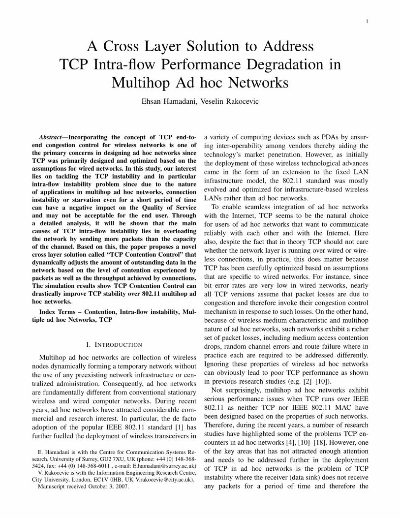
2) TCP and 802.11 control packets interferenceThe other type of intra-flow interference in thelink layer happens between the TCP packets (TCPDATA or TCP ACK) and one of the 802.11 controlpackets (RTS, CTS, or MACK). However, it is im-portant to note that regarding 802.11 MAC timingspecification, the DCF protocol ensures that CTSframe transmission will be successfully received atits destination (the one who sent the RTS), if theCTS frame has been issued in response to the RTS.This is because successful RTS frame transmissionsilences all the nodes in the neighborhood ofthe source either for a duration specified in theduration field of the RTS or for EIFS time (ifcollision occurs) which is large enough to transmita CTS. Therefore, the CTS frame cannot collidewith any frame at the source. Using a similar ar-gument, it can be concluded that a successful TCPframe transmission ensures a successful MACK
frame transmission. Thus, there cannot be CTS andMACK frames drop at the intended destination (thenode who is waiting to receive the packet) becauseof medium contention.Figure 2 reviews one the most common scenariosof TCP packet drop due to 802.11 control and TCPpackets collision.
A
B
C
D
E
F
G
RTS RTS
CTS
DATA
RTS
RTS retransmission
DATA RTS retransmission
RTS retransmission
Figure 2: RTS & TCP DATA collision
Here, station D has TCP DATA to send to Eand it sends its data after a RTS/CTS handshakewith node E. Meanwhile B has a TCP DATA tosend to C, thus starts its own RTS handshake.However, due to ongoing TCP DATA transmissionbetween D and E, the B’s RTS is dropped at C.Although B resends the RTS after performing anexponential backoff, in most of the cases all itsRTS retransmissions (7 by default) are collidedat node C and therefore node B drops the TCPpacket1.
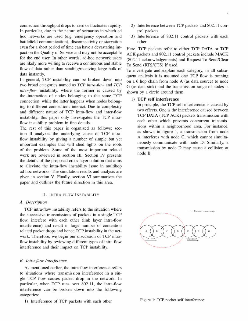
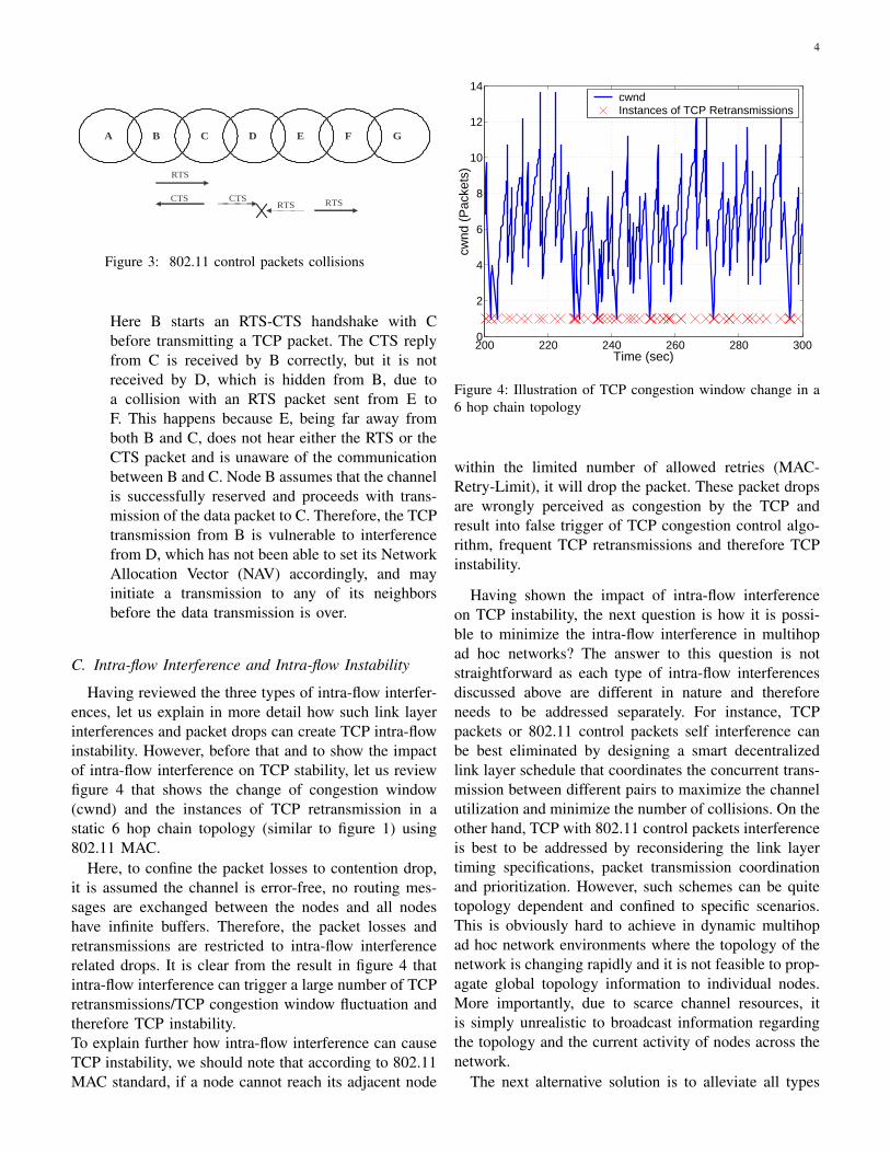
3) 802.11 control packets self interferenceThe last type of intra-flow interference happensbetween 802.11 RTS, CTS control packets if theRTS/CTS handshake is used prior to data trans-mission. We should note that despite the smallsize of RTS and CTS packets compared to datapackets, the frequent losses of control packetscan waste channel resources and have undesirableimpact on the performance of higher layers. Onthe other hand, the self interference between theRTS and CTS control packets can fail the channelreservation scheme and lead to a loss of datapackets as well. Figure 3 depicts a typical scenarioof control packets self interference and loss of TCPpacket as a result.
1This is due to the relatively large amount of time the channel isoccupied when sending TCP DATA.
4
A
B
C
D
E
F
G
RTS
RTS CTS RTS CTS
Figure 3: 802.11 control packets collisions
Here B starts an RTS-CTS handshake with Cbefore transmitting a TCP packet. The CTS replyfrom C is received by B correctly, but it is notreceived by D, which is hidden from B, due toa collision with an RTS packet sent from E toF. This happens because E, being far away fromboth B and C, does not hear either the RTS or theCTS packet and is unaware of the communicationbetween B and C. Node B assumes that the channelis successfully reserved and proceeds with trans-mission of the data packet to C. Therefore, the TCPtransmission from B is vulnerable to interferencefrom D, which has not been able to set its NetworkAllocation Vector (NAV) accordingly, and mayinitiate a transmission to any of its neighborsbefore the data transmission is over.
C. Intra-flow Interference and Intra-flow Instability
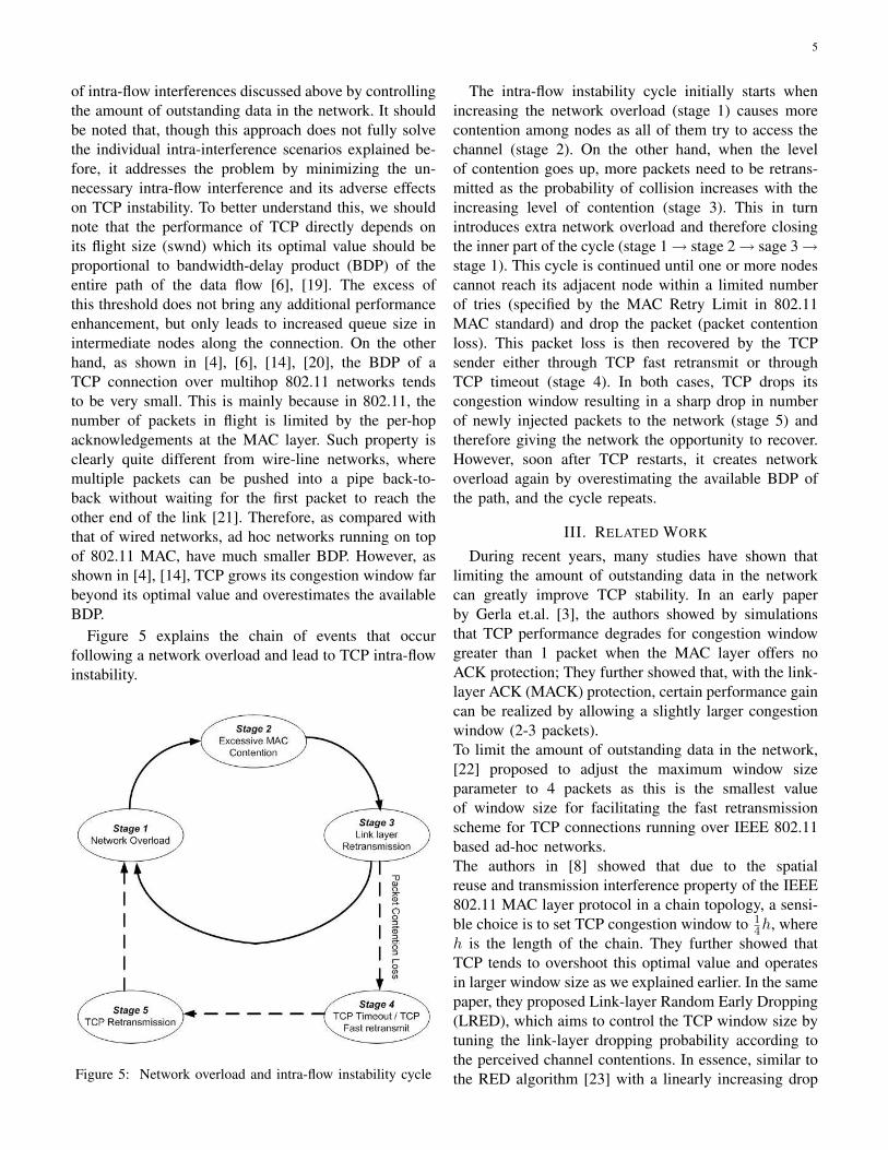
Having reviewed the three types of intra-flow interfer-ences, let us explain in more detail how such link layerinterferences and packet drops can create TCP intra-flowinstability. However, before that and to show the impactof intra-flow interference on TCP stability, let us reviewfigure 4 that shows the change of congestion window(cwnd) and the instances of TCP retransmission in astatic 6 hop chain topology (similar to figure 1) using802.11 MAC.
Here, to confine the packet losses to contention drop,it is assumed the channel is error-free, no routing mes-sages are exchanged between the nodes and all nodeshave infinite buffers. Therefore, the packet losses andretransmissions are restricted to intra-flow interferencerelated drops. It is clear from the result in figure 4 thatintra-flow interference can trigger a large number of TCPretransmissions/TCP congestion window fluctuation andtherefore TCP instability.To explain further how intra-flow interference can causeTCP instability, we should note that according to 802.11MAC standard, if a node cannot reach its adjacent node
200 220 240 260 280 3000
2
4
6
8
10
12
14
Time (sec)
cwnd
(P
acke
ts)
cwndInstances of TCP Retransmissions
Figure 4: Illustration of TCP congestion window change in a6 hop chain topology
within the limited number of allowed retries (MAC-Retry-Limit), it will drop the packet. These packet dropsare wrongly perceived as congestion by the TCP andresult into false trigger of TCP congestion control algo-rithm, frequent TCP retransmissions and therefore TCPinstability.
Having shown the impact of intra-flow interferenceon TCP instability, the next question is how it is possi-ble to minimize the intra-flow interference in multihopad hoc networks? The answer to this question is notstraightforward as each type of intra-flow interferencesdiscussed above are different in nature and thereforeneeds to be addressed separately. For instance, TCPpackets or 802.11 control packets self interference canbe best eliminated by designing a smart decentralizedlink layer schedule that coordinates the concurrent trans-mission between different pairs to maximize the channelutilization and minimize the number of collisions. On theother hand, TCP with 802.11 control packets interferenceis best to be addressed by reconsidering the link layertiming specifications, packet transmission coordinationand prioritization. However, such schemes can be quitetopology dependent and confined to specific scenarios.This is obviously hard to achieve in dynamic multihopad hoc network environments where the topology of thenetwork is changing rapidly and it is not feasible to prop-agate global topology information to individual nodes.More importantly, due to scarce channel resources, itis simply unrealistic to broadcast information regardingthe topology and the current activity of nodes across thenetwork.
The next alternative solution is to alleviate all types
5
of intra-flow interferences discussed above by controllingthe amount of outstanding data in the network. It shouldbe noted that, though this approach does not fully solvethe individual intra-interference scenarios explained be-fore, it addresses the problem by minimizing the un-necessary intra-flow interference and its adverse effectson TCP instability. To better understand this, we shouldnote that the performance of TCP directly depends onits flight size (swnd) which its optimal value should beproportional to bandwidth-delay product (BDP) of theentire path of the data flow [6], [19]. The excess ofthis threshold does not bring any additional performanceenhancement, but only leads to increased queue size inintermediate nodes along the connection. On the otherhand, as shown in [4], [6], [14], [20], the BDP of aTCP connection over multihop 802.11 networks tendsto be very small. This is mainly because in 802.11, thenumber of packets in flight is limited by the per-hopacknowledgements at the MAC layer. Such property isclearly quite different from wire-line networks, wheremultiple packets can be pushed into a pipe back-to-back without waiting for the first packet to reach theother end of the link [21]. Therefore, as compared withthat of wired networks, ad hoc networks running on topof 802.11 MAC, have much smaller BDP. However, asshown in [4], [14], TCP grows its congestion window farbeyond its optimal value and overestimates the availableBDP.
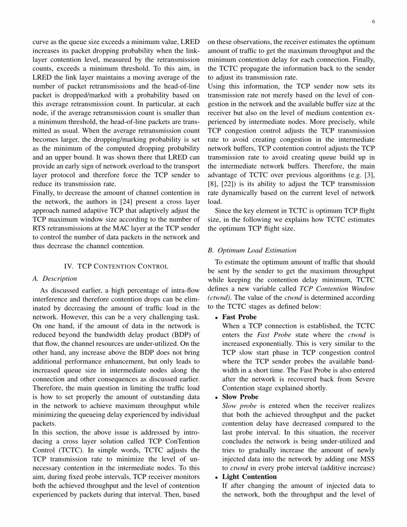
Figure 5 explains the chain of events that occurfollowing a network overload and lead to TCP intra-flowinstability.
Figure 5: Network overload and intra-flow instability cycle
The intra-flow instability cycle initially starts whenincreasing the network overload (stage 1) causes morecontention among nodes as all of them try to access thechannel (stage 2). On the other hand, when the levelof contention goes up, more packets need to be retrans-mitted as the probability of collision increases with theincreasing level of contention (stage 3). This in turnintroduces extra network overload and therefore closingthe inner part of the cycle (stage 1→ stage 2→ sage 3→stage 1). This cycle is continued until one or more nodescannot reach its adjacent node within a limited numberof tries (specified by the MAC Retry Limit in 802.11MAC standard) and drop the packet (packet contentionloss). This packet loss is then recovered by the TCPsender either through TCP fast retransmit or throughTCP timeout (stage 4). In both cases, TCP drops itscongestion window resulting in a sharp drop in numberof newly injected packets to the network (stage 5) andtherefore giving the network the opportunity to recover.However, soon after TCP restarts, it creates networkoverload again by overestimating the available BDP ofthe path, and the cycle repeats.
III. RELATED WORK
During recent years, many studies have shown thatlimiting the amount of outstanding data in the networkcan greatly improve TCP stability. In an early paperby Gerla et.al. [3], the authors showed by simulationsthat TCP performance degrades for congestion windowgreater than 1 packet when the MAC layer offers noACK protection; They further showed that, with the link-layer ACK (MACK) protection, certain performance gaincan be realized by allowing a slightly larger congestionwindow (2-3 packets).To limit the amount of outstanding data in the network,[22] proposed to adjust the maximum window sizeparameter to 4 packets as this is the smallest valueof window size for facilitating the fast retransmissionscheme for TCP connections running over IEEE 802.11based ad-hoc networks.The authors in [8] showed that due to the spatialreuse and transmission interference property of the IEEE802.11 MAC layer protocol in a chain topology, a sensi-ble choice is to set TCP congestion window to 1
4h, whereh is the length of the chain. They further showed thatTCP tends to overshoot this optimal value and operatesin larger window size as we explained earlier. In the samepaper, they proposed Link-layer Random Early Dropping(LRED), which aims to control the TCP window size bytuning the link-layer dropping probability according tothe perceived channel contentions. In essence, similar tothe RED algorithm [23] with a linearly increasing drop
6
curve as the queue size exceeds a minimum value, LREDincreases its packet dropping probability when the link-layer contention level, measured by the retransmissioncounts, exceeds a minimum threshold. To this aim, inLRED the link layer maintains a moving average of thenumber of packet retransmissions and the head-of-linepacket is dropped/marked with a probability based onthis average retransmission count. In particular, at eachnode, if the average retransmission count is smaller thana minimum threshold, the head-of-line packets are trans-mitted as usual. When the average retransmission countbecomes larger, the dropping/marking probability is setas the minimum of the computed dropping probabilityand an upper bound. It was shown there that LRED canprovide an early sign of network overload to the transportlayer protocol and therefore force the TCP sender toreduce its transmission rate.Finally, to decrease the amount of channel contention inthe network, the authors in [24] present a cross layerapproach named adaptive TCP that adaptively adjust theTCP maximum window size according to the number ofRTS retransmissions at the MAC layer at the TCP senderto control the number of data packets in the network andthus decrease the channel contention.
IV. TCP CONTENTION CONTROL
A. Description
As discussed earlier, a high percentage of intra-flowinterference and therefore contention drops can be elim-inated by decreasing the amount of traffic load in thenetwork. However, this can be a very challenging task.On one hand, if the amount of data in the network isreduced beyond the bandwidth delay product (BDP) ofthat flow, the channel resources are under-utilized. On theother hand, any increase above the BDP does not bringadditional performance enhancement, but only leads toincreased queue size in intermediate nodes along theconnection and other consequences as discussed earlier.Therefore, the main question in limiting the traffic loadis how to set properly the amount of outstanding datain the network to achieve maximum throughput whileminimizing the queueing delay experienced by individualpackets.In this section, the above issue is addressed by intro-ducing a cross layer solution called TCP ConTentionControl (TCTC). In simple words, TCTC adjusts theTCP transmission rate to minimize the level of un-necessary contention in the intermediate nodes. To thisaim, during fixed probe intervals, TCP receiver monitorsboth the achieved throughput and the level of contentionexperienced by packets during that interval. Then, based
on these observations, the receiver estimates the optimumamount of traffic to get the maximum throughput and theminimum contention delay for each connection. Finally,the TCTC propagate the information back to the senderto adjust its transmission rate.Using this information, the TCP sender now sets itstransmission rate not merely based on the level of con-gestion in the network and the available buffer size at thereceiver but also on the level of medium contention ex-perienced by intermediate nodes. More precisely, whileTCP congestion control adjusts the TCP transmissionrate to avoid creating congestion in the intermediatenetwork buffers, TCP contention control adjusts the TCPtransmission rate to avoid creating queue build up inthe intermediate network buffers. Therefore, the mainadvantage of TCTC over previous algorithms (e.g. [3],[8], [22]) is its ability to adjust the TCP transmissionrate dynamically based on the current level of networkload.
Since the key element in TCTC is optimum TCP flightsize, in the following we explains how TCTC estimatesthe optimum TCP flight size.
B. Optimum Load Estimation
To estimate the optimum amount of traffic that shouldbe sent by the sender to get the maximum throughputwhile keeping the contention delay minimum, TCTCdefines a new variable called TCP Contention Window(ctwnd). The value of the ctwnd is determined accordingto the TCTC stages as defined below:• Fast Probe
When a TCP connection is established, the TCTCenters the Fast Probe state where the ctwnd isincreased exponentially. This is very similar to theTCP slow start phase in TCP congestion controlwhere the TCP sender probes the available band-width in a short time. The Fast Probe is also enteredafter the network is recovered back from SevereContention stage explained shortly.
• Slow ProbeSlow probe is entered when the receiver realizesthat both the achieved throughput and the packetcontention delay have decreased compared to thelast probe interval. In this situation, the receiverconcludes the network is being under-utilized andtries to gradually increase the amount of newlyinjected data into the network by adding one MSSto ctwnd in every probe interval (additive increase)
• Light ContentionIf after changing the amount of injected data tothe network, both the throughput and the level of
7
packet contention delay are increased, the TCTCenters Light Contention stage. In Light Contentionstage, the TCTC slowly decreases the ctwnd byone MSS per probe interval to control the amountof outstanding data in the network while avoidingunnecessary reduction in TCP throughput by imple-menting additive decrease. In other words, the Lightcontention stage is entered when the network is inearly stages of overload.
• Severe ContentionSevere Contention stage is entered whenever thereceiver sees an increase in the level of contentiondelay while the achieved throughput has been de-creased. This situation is a clear sign of networkoverload since it shows the push of more data intothe network has just increased the amount of con-tention experienced by individual packets withoutincreasing the throughput seen by the receiver. Thissituation can also happen if suddenly the level ofcontention in the network increases (e.g. a secondconnection starts using the intermediate nodes). Tocombat this, the TCTC sets its ctwnd to 2*MSS toforce the sender to minimize its transmission rate.
The pseudo code in Algorithm 1, summarizes the calcu-lation of ctwnd in different stages.
It is important to note that because of TCP DelayedACK algorithm [25], the minimum ctwnd in TCTC is setto 2*MSS to make sure at least 2 segments are in thenetwork and can trigger the transmission of TCP ACKat the receiver without waiting for maximum ACK delaytimer to expire.
As it can be seen in Algorithm 1, the condition onwhich stages are entered is according to the value oftwo parameters named DeltaThroughput (∆Throughput)and DeltaContention, (∆Contention).DeltaThroughput, which is calculated as in formula 1,simply compares the amount of data received by thereceiver (in Bytes) in the current probe interval (probe-new) and the last probe interval (probe-old)
∆Throughput =(data received)probe-new ∗ (probe-old)(data received)probe-old ∗ (probe-new)
(1)DeltaContention on the other hand compares the av-
erage amount of contention delay experienced by allpackets during the current probe interval with the averagecontention delay experienced by packets during the lastprobe interval. In the next subsection, we explain howDeltaContention acquires the required information oncontention delay values.
C. Contention Delay Measurement
The main objective of measuring contention delay isto reflect the current level of contention in the network.To this aim, the contention delay is measured from thetime a node places the first fragment of that packetat the beginning of a buffer until the packet leavesthe buffer for actual transmission on the physical layer.Also, the contention delay timer inside each node onlyresets to zero when the node receives a MACK. In thismanner the contention delay includes the period for thesuccessful RTS/CTS exchange, if this exchange is usedfor the packet. In addition, the contention delay for aretransmitted packet will start from time the originalpacket was placed in the head of the buffer for thefirst time until the corresponding MACK is received. Ifafter reaching maximum retry limit, the packet cannotbe transmitted, the value of contention delay is added tothe contention delay of the next packet.
The value of measured contention delay is then in-serted inside the Contention Delay Field (CDF) usingthe optional field in 802.11 MAC. More precisely, eachpacket records the contention delay it experienced ineach node and add the new contention delay to the CDF.In this manner, the Cumulative Contention Delay (CCD)experienced by each packet along the path are deliveredto the final receiver (TCP receiver). The TCP receiverthen calculates the value of Contention Delay per Hop(CDH) by dividing the CCD by total number of hopstraversed by that specific packet. The main property ofCDH is its independency from number of hops traversedby the packet. Finally the receiver derives the MeanContention Delay per Hop (MCDH) by calculating themean value of CDH received during each probe interval.
Having the value of MCDH, the DeltaContention asshown in equation 2 is derived by comparing the MCDHreceived by the receiver in current probe interval (probe-new) and the last probe interval (probe-old)
∆Contention =MCDHprobe−new
MCDHprobe−old(2)
D. Contention Delay Field
To carry the value of CDF inside a packet, we use theextended IEEE 802.11 MAC protocol packet format withoptional fields inside the MAC header as suggested in[26]. In essence, a new field called "options" is proposedas a variable length field which extends standard MACheader. To perform separation of the data encapsulatedinto the frame from the MAC header, the option containsa Header Length field which specifies the entire lengthof the MAC header, including the list of options. Inaddition, each option consists of option type, length and

8
Algorithm 1 PSEUDO CODE OF CALCULATING CTWND IN DIFFERENT STAGES
if ∆Throughput ≥ 1 thenif ∆Contention > 1 then
TCP_Contention = TCP_Contention− MSS∗MSSTCP _Contention // Light Contention
elseTCP_Contention = TCP_Contention + MSS // Fast Probe
end ifelse
if ∆Contention > 1 thenTCP_Contention = TCP_Contention + 2 ∗MSS // Severe Contention
elseTCP_Contention = TCP_Contention + MSS∗MSS
TCP _Contention // Slow Probeend if
end ifif TCP_Contention ≤ 2 ∗MSS then
TCP_Contention = 2 ∗MSSend if
data as shown in figure 6. The Header Length field isrequired to handle the case when a node does not supportthe corresponding option and therefore the knowledgeof the option’s length makes skipping the current optioneasier, jumping to the next one for processing.
Figure 6: Options-enabled IEEE 802.11 data frame
Since in the proposed model, the only option beingused is the CDF field, the 802.11 data packet supportingcontention delay field is similar to figure 7 with theFrame Control value of 101000.
Figure 7: CDF-enabled IEEE 802.11 data frame
Note that here we have introduced a new type of datapacket using the available reserved types in the FrameControl field of the MAC header of data frames. In
particular, our frame "type" is equal to "10" (Data packet)and the "subtype" is set to "1000" as an indication ofCDF-enabled data frame. This is to provide backwardsupport within the existing IEEE 802.11 standard spec-ification, since a CDF-enabled data frame should be ofa different type with respect to a normal data frame.
E. Propagating the Contention Delay Information
Having calculated the optimum value of network over-load over the next period of the probe interval, the nextquestion is how to propagate this information (which isstored in ctwnd) back to the sender so the TCP sendercan adjusts its transmission rate accordingly. To answerthat, we should note that the TCP sender cannot havea number of outstanding segments larger than the rwndwhich is advertised by its own receiver. By default, theTCP receiver advertises its available receiving buffersize, in order to avoid saturation by a fast connection(flow control). We propose to extend the use of rwnd toaccommodate the value of ctwnd in order to allow thereceiver to limit the transmission rate of the TCP senderalso when the path used by the connection exhibits ahigh contention and frame collision probability as wellas its default flow control mechanism. In other words,when TCTC is used, the new value of rwnd becomesthe minimum of the available buffer size of the receiver(available receiver buffer) and the current value of ctwndas shown below in equation 3.
rwnd = Min(available receiver buffer, ctwnd) (3)
9
F. Choice of Probe Interval
It is clear from the above discussions that the choice ofprobe interval at the receiver can affect the performanceof TCTC. Too large probe interval means that TCTCresponds too slowly to contention changes in the networkwhile too small probe interval will make TCTC sensitiveto contention delay experienced by individual packetsand therefore leads to ctwnd fluctuation. Heuristically,the probe interval of one RTT seems to be the natural andreasonable choice as it gives the receiver enough timeto monitor the packets it received during one RTT andthen sets its recommendation of sender’s transmissionrate (using ctwnd) for the next RTT. However, to providethe receiver with the correct and up to date informationon the impact of previous ctwnd on the level of networkcontention, the ctwnd should be updated in every otherRTT. Therefore, we recommend the ctwnd gets updatedevery 2*RTT and remains fixed between two updates.In this way, the receiver can make sure the packets ithas received are sent into the network after the senderhas applied the changes imposed by the receiver inthe last probe interval. Having the value of the TCTCprobe interval, the other major issue is that TCP receiver(which is running the TCTC algorithm) is unaware ofconnection’s RTT2. This problem can be solved by usingthe fact that according to [27], in a small to mediumsize ad hoc networks the congestion window size (i.e.number of packets sent per RTT) does not grow beyond 5packets. Therefore, considering this estimation togetherwith the discussion given earlier, the probe interval inreceiver can be defined as the period in which 2*5=10packets are received. Note that although this is a roughestimation, it clearly solves our design objectives ofprobe interval which is merely the frequency of updatingTCTC.
V. RESULTS
A. Simulation Model
All simulations are performed using OPNET simulator[28]. The transmission range is set to 100m according tothe 802.11b testbed measurements presented in [13]. Inphysical layer Direct Sequence Spread Spectrum (DSSS)technology with 2Mbps data rate is adopted and thechannel uses free-space with no external noise. Eachnode has a 20 packet MAC layer buffer pool and in allscenarios, the application operates in asymptotic condi-tion (i.e., it always has packets ready for transmission).The scheduling of packet transmission is FIFO. Nodes
2assuming the receiver is not sending any data packets towardsTCP sender or there is a route asymmetry between the forward andreturn path
use DSR as the routing protocol. In transport layer, TCPNewReno flavor is deployed and the TCP advertisedwindow is set its maximum value of 64KB so thereceiver buffer size does not affect the TCP congestionwindow size. TCP MSS size is assumed to be fixed at1460B. RTS/CTS message exchange is used for packetslarger than 256B (therefore no RTS/CTS is done forTCP-ACK packets). The number of retransmission atMAC layer is set to 4 for packets greater than 256B(Long_Retry_Limit) and 7 for other packets (Short_Retry_Limit) as has been specified in IEEE 802.11 MACstandard. All scenarios unless otherwise stated, consistof nodes with no mobility.
B. Simulation Results
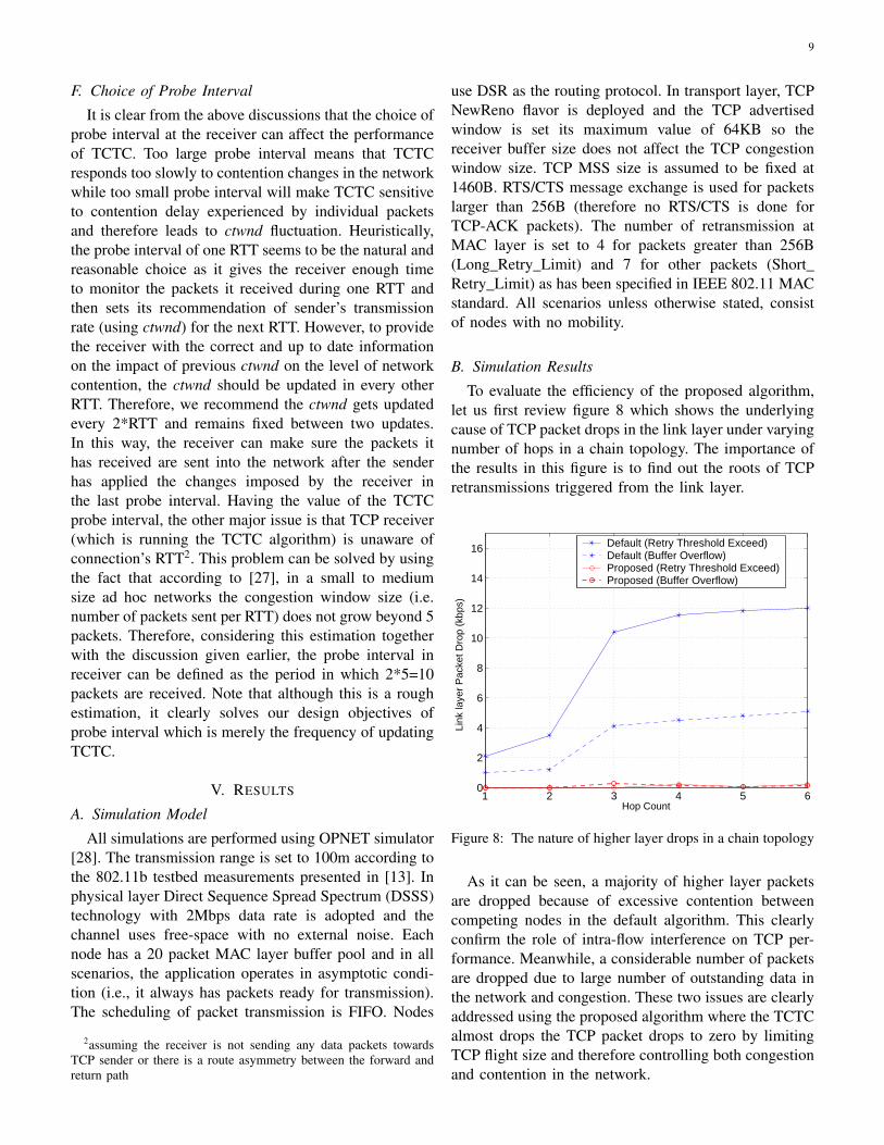
To evaluate the efficiency of the proposed algorithm,let us first review figure 8 which shows the underlyingcause of TCP packet drops in the link layer under varyingnumber of hops in a chain topology. The importance ofthe results in this figure is to find out the roots of TCPretransmissions triggered from the link layer.
1 2 3 4 5 60
2
4
6
8
10
12
14
16
Hop Count
Link
laye
r P
acke
t Dro
p (k
bps)
Default (Retry Threshold Exceed)Default (Buffer Overflow)Proposed (Retry Threshold Exceed)Proposed (Buffer Overflow)
Figure 8: The nature of higher layer drops in a chain topology
As it can be seen, a majority of higher layer packetsare dropped because of excessive contention betweencompeting nodes in the default algorithm. This clearlyconfirm the role of intra-flow interference on TCP per-formance. Meanwhile, a considerable number of packetsare dropped due to large number of outstanding data inthe network and congestion. These two issues are clearlyaddressed using the proposed algorithm where the TCTCalmost drops the TCP packet drops to zero by limitingTCP flight size and therefore controlling both congestionand contention in the network.
10
0 100 200 300 400 500 6000
100
200
300
400
500
600
700
800
Time (sec)
TC
P S
egm
ent D
elay
(m
s)
DefaultProposed
(a) 1 hop
0 100 200 300 400 500 6000
100
200
300
400
500
600
700
800
Time (sec)
TC
P S
egm
ent D
eay
(ms)
DefaultProposed
(b) 2 hop
0 100 200 300 400 500 6000
100
200
300
400
500
600
700
800
Time (sec)
TC
P S
egm
ent D
elay
(m
s)
DefaultProposed
(c) 3 hop
0 100 200 300 400 500 6000
100
200
300
400
500
600
700
800
Time (sec)
TC
P S
egm
ent D
elay
(m
s)
DefaultProposed
(d) 4 hop
0 100 200 300 400 500 6000
100
200
300
400
500
600
700
800
Time (sec)
TC
P S
egm
ent D
elay
(m
s)
DefaultProposed
(e) 5 hop
0 100 200 300 400 500 6000
100
200
300
400
500
600
700
800
Time (sec)
TC
P S
egm
ent D
elay
(m
s)
DefaultProposed
(f) 6 hop
Figure 9: TCP segment delay in a chain topology
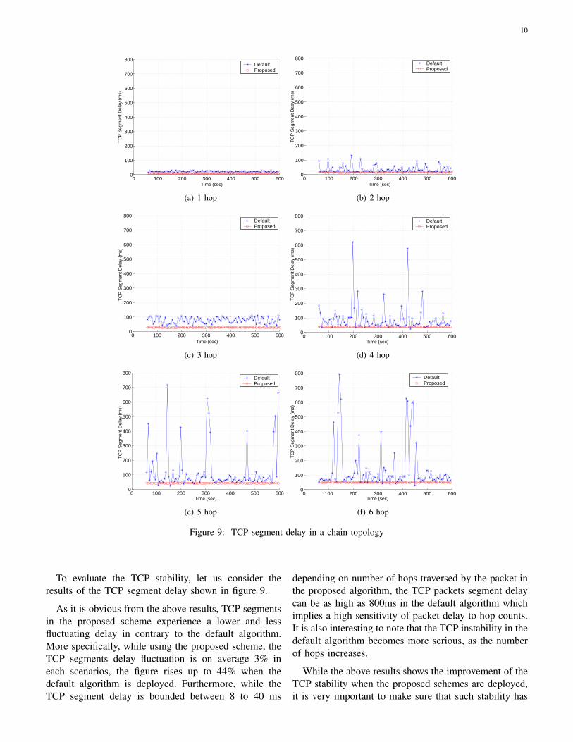
To evaluate the TCP stability, let us consider theresults of the TCP segment delay shown in figure 9.
As it is obvious from the above results, TCP segmentsin the proposed scheme experience a lower and lessfluctuating delay in contrary to the default algorithm.More specifically, while using the proposed scheme, theTCP segments delay fluctuation is on average 3% ineach scenarios, the figure rises up to 44% when thedefault algorithm is deployed. Furthermore, while theTCP segment delay is bounded between 8 to 40 ms
depending on number of hops traversed by the packet inthe proposed algorithm, the TCP packets segment delaycan be as high as 800ms in the default algorithm whichimplies a high sensitivity of packet delay to hop counts.It is also interesting to note that the TCP instability in thedefault algorithm becomes more serious, as the numberof hops increases.
While the above results shows the improvement of theTCP stability when the proposed schemes are deployed,it is very important to make sure that such stability has
11
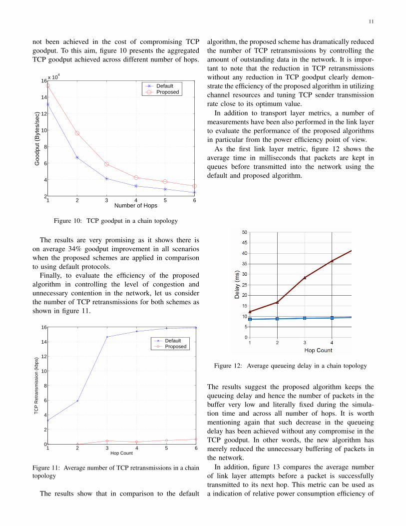
not been achieved in the cost of compromising TCPgoodput. To this aim, figure 10 presents the aggregatedTCP goodput achieved across different number of hops.
1 2 3 4 5 62
4
6
8
10
12
14
16x 10
4
Number of Hops
Goo
dput
(B
ytes
/sec
)
DefaultProposed
Figure 10: TCP goodput in a chain topology
The results are very promising as it shows there ison average 34% goodput improvement in all scenarioswhen the proposed schemes are applied in comparisonto using default protocols.
Finally, to evaluate the efficiency of the proposedalgorithm in controlling the level of congestion andunnecessary contention in the network, let us considerthe number of TCP retransmissions for both schemes asshown in figure 11.
1 2 3 4 5 60
2
4
6
8
10
12
14
16
Hop Count
TC
P R
etra
nsm
issi
on (
kbps
)
DefaultProposed
Figure 11: Average number of TCP retransmissions in a chaintopology
The results show that in comparison to the default
algorithm, the proposed scheme has dramatically reducedthe number of TCP retransmissions by controlling theamount of outstanding data in the network. It is impor-tant to note that the reduction in TCP retransmissionswithout any reduction in TCP goodput clearly demon-strate the efficiency of the proposed algorithm in utilizingchannel resources and tuning TCP sender transmissionrate close to its optimum value.
In addition to transport layer metrics, a number ofmeasurements have been also performed in the link layerto evaluate the performance of the proposed algorithmsin particular from the power efficiency point of view.
As the first link layer metric, figure 12 shows theaverage time in milliseconds that packets are kept inqueues before transmitted into the network using thedefault and proposed algorithm.
Figure 12: Average queueing delay in a chain topology
The results suggest the proposed algorithm keeps thequeueing delay and hence the number of packets in thebuffer very low and literally fixed during the simula-tion time and across all number of hops. It is worthmentioning again that such decrease in the queueingdelay has been achieved without any compromise in theTCP goodput. In other words, the new algorithm hasmerely reduced the unnecessary buffering of packets inthe network.
In addition, figure 13 compares the average numberof link layer attempts before a packet is successfullytransmitted to its next hop. This metric can be used asa indication of relative power consumption efficiency of

12
different algorithms.
1 2 3 4 5 61
1.1
1.2
1.3
1.4
1.5
1.6
1.7
1.8
1.9
Number of Hops
Num
ber
of A
ttem
pts
ProposedDefault
Figure 13: Average link layer attempts in a chain topology
From the results presented there, it can be claimedthat on average 32% less transmission is required in theproposed scheme compared to the default algorithm todeliver the same amount of link layer data traffic. In otherwords, the proposed algorithm can reduce the number ofunnecessary packet transmission by a factor of one thirdand therefore can save considerable amount of energy.
C. Impact of Probe Interval
As discussed in subsection IV-F, the probe interval isthe number of samples in which the receiver updatesits contention delay window (ctwnd). As mentionedthere, the main importance of the probe interval is todetermine the sensitivity of the receiver to the contentiondelay information received from individual packets. Notethat the choice of the probe interval becomes importantwhen for any reason (e.g. start of new connection in theinterference range of one or more of the nodes alongthat connection), the level of contention experiencedby packets changes during the connection period. Tosimulate such scenario, we used a topology shown infigure 14 where connection 1 (from node A o B) startsat time 0 and runs until the end of simulation whileconnection 2 (from node F to G) starts at time 250seconds and lasts for 100 seconds.
To show the impact of different probe interval onsystem performance, the average number of bufferedpackets across all nodes has been used as shown in figure15.
The results confirm first of all a short probe interval(e.g. 2 packets) can lead to fluctuation and thereforeinstability in the network as the calculation of ctwnd
Figure 14: 4 hop chain topology with interference
0 100 200 300 400 500 6001
1.1
1.2
1.3
1.4
1.5
1.6
1.7
1.8
1.9
2
Time (sec)
Buf
fer
Siz
e (P
acke
ts)
Probe interval = 50 packetsProbe interval = 10 packetsProbe interval = 2 packets
Figure 15: Impact of probe interval choice on buffer size
becomes very sensitive to the contention delay expe-rienced by individual packets. On the other hand, ifa large probe interval such as 50 packets is chosen,the convergence time (i.e. the time it takes for thealgorithm to adjusts itself to new situation) can beconsiderable (as large as 60 seconds). This is definitelyunacceptable since if during the probe interval time,the contention level increases (e.g. time 250 seconds infigure 15 when connection 2 starts), connection 1 willexperience a severe delay and packet retransmissionsas node B does not update its ctwnd before the endof current probe interval. On the other hand, if duringthe probe interval time, the contention level decreases(e.g. time 350 seconds in figure 15 when connection2 stops), the channel resources would be underutilizedas node B restricts node A from accessing the newlyavailable bandwidth. Although the exact value of theoptimum probe interval depends on individual situations,the simulation results suggest values between 10 to 15packets satisfy the objectives of introducing the probe
13
interval.
VI. CONCLUSION AND FUTURE WORK
Improving the performance of TCP over 802.11 multi-hop ad hoc networks is truly a cross-layer problem.To fully benefit from the flexibility and advantages ofmultihop ad hoc networks, there is a clear need forimprovement of the way TCP operates in such net-works. This paper studied thoroughly the problem ofTCP intra-flow instability in multihop ad hoc networks.In particular, it was shown in this paper that a largenumber of outstanding TCP packets in the network isone of the primary cause of TCP intra-flow instability. Totackle the problem, we proposed a cross layer algorithmcalled TCP Contention Control that it adjust the amountof outstanding data in the network based on the levelof contention experienced by packets as well as thethroughput achieved by connections. The main featuresof this algorithm is its flexibility and adaptation tothe network conditions. Furthermore, TCP ContentionControl is compatible with all TCP versions and itdoes not require any changes in TCP congestion controlalgorithm since it simply uses the existing TCP to throttlethe amount of outstanding data in the network. Thiscan be very useful in heterogeneous networks (wire +wireless) where the same TCP can be used in bothnetworks. Therefore, comprehensive simulations shouldbe conducted to evaluate the capability of the proposedschemes when the connection is expanding from wire towireless networks or vice versa
REFERENCES
[1] “IEEE Standards for Wireless LAN Medium Access Control(MAC) and Physical Layer (PHY),Part 11:Technical Specifica-tions,” 1999.
[2] R. Caceres and L. Iftode, “Improving the Performance of Reli-able Transport Protocols in Mobile Computing Environments,”IEEE Journal on Selected Areas in Communications, vol. 13,no. 5, pp. 850 – 857, 1995.
[3] M. Gerla, R. Bagrodia, L. Zhang, K. Tang, and L. Wang, “TCPover Wireless Multi-Hop Protocols: Simulation and Experi-ments,” Proceedings - IEEE ICC, vol. Vol 2, pp. 1089–1094,1999.
[4] Z. Fu, X. Meng, and S. Lu, “How Bad TCP Can Perform inMobile Ad Hoc Networks,” Proceedings- IEEE InternationalSymposium on Computers and Communications, pp. 298–303,2002.
[5] X. Li, P.-Y. Kong, and K.-C. Chua, “Analysis of TCP Through-put in IEEE 802.11 Based Multi-hop Ad hoc Networks,”Proceedings - International Conference on Computer Commu-nications and Networks, ICCCN, vol. 2005, pp. 297 – 302,2005.
[6] X. Chen, H. Zhai, J. Wang, and Y. Fang, “TCP Performanceover Mobile Ad Hoc Networks,” Canadian Journal of Electricaland Computer Engineering, vol. 29, no. 1, pp. 129 – 134, 2004.
[7] M. D. Baba, N. Ahmad, M. Ibrahim, R. A. Rahman, and N. H.Eshak, “Performance Evaluation of TCP/IP Protocol for MobileAd hoc Network,” WSEAS Transactions on Computers, vol. 5,no. 7, pp. 1481 – 1486, 2006.
[8] Z. Fu, P. Zerfos, H. Luo, S. Lu, L. Zhang, and M. Gerla, “TheImpact of Multihop Wireless Channel on TCP Throughput andLoss,” Proceedings - IEEE INFOCOM, vol. 3, pp. 1744 – 1753,2003.
[9] Y. Wang, K. Yu, Y. Liu, and H. Zhang, “Analysis and Im-provement of TCP Performance in Mobile Ad Hoc Networks,”International Conference on Communication Technology Pro-ceedings, vol. 2, pp. 1301 – 1304, 2003.
[10] W. Xu and T. Wu, “TCP issues in mobile ad hoc networks:Challenges and solutions,” Journal of Computer Science andTechnology, vol. 21, no. 1, pp. 72 – 81, 2006.
[11] H. Lim, K. Xu, and M. Gerla, “TCP Performance over Multi-path Routing in Mobile Ad Hoc Networks,” IEEE InternationalConference on Communications, vol. 2, pp. 1064 – 1068, 2003.
[12] H. Elaarag, “Improving TCP Performance over Mobile Net-works,” ACM Computing Surveys, vol. 34, no. 3, pp. 357 –374, 2002.
[13] A. Ahuja, S. Agarwal, J. P. Singh, and R. Shorey, “Perfor-mance of TCP over different routing protocols in mobile ad-hoc networks,” IEEE Vehicular Technology Conference, vol. 3,pp. 2315 – 2319, 2000.
[14] Z. Fu, H. Luo, P. Zerfos, S. Lu, L. Zhang, and M. Gerla, “TheImpact of Multihop Wireless Channel on TCP Performance,”IEEE Transactions on Mobile Computing, vol. 4, no. 2, pp. 209– 221, 2005.
[15] L. Zhang, X. Wang, and W. Dou, “Analyzing and Improvingthe TCP Flow Fairness in Wireless Ad Hoc Networks,” RuanJian Xue Bao/Journal of Software, vol. 17, no. 5, pp. 1078 –1088, 2006.
[16] H. Zhai, X. Chen, and Y. Fang, “Improving Transport LayerPerformance In Multihop Ad Hoc Networks by ExploitingMAC Layer Information,” IEEE Transactions on Wireless Com-munications, vol. 6, no. 5, pp. 1692 – 1701, 2007.
[17] S. Xu and T. Saadawi, “Revealing the Problems with 802.11Medium Access Control Protocol in Multi-Hop Wireless AdHoc Networks,” Computer Networks, vol. 38, no. 4, pp. 531 –548, 2002.
[18] H. Balakrishnan and V. Padmanabhan, “How Network Asym-metry Affects TCP,” IEEE Communications Magazine, vol. 39,no. 4, pp. 60 – 67, 2001.
[19] K. Chen, Y. Xue, and K. Nahrstedt, “On Setting TCP’s Con-gestion Window Limit in Mobile Ad Hoc Networks,” IEEEInternational Conference on Communications, vol. 2, pp. 1080– 1084, 2003.
[20] J. Song, K. Ahn, D. Cho, and K. Han, “A Congestion WindowAdjustment Scheme for Improving TCP Performance OverMobile Ad-Hoc Networks,” Lecture Notes in Computer Science,vol. 4104 NCS, pp. 404 – 413, 2006.
[21] D. Katabi, M. Handley, and C. Rohrs, “Congestion Control forHigh Bandwidth-Delay Product Networks,” Computer Commu-nication Review, vol. 32, no. 4, pp. 89 – 102, 2002.
[22] S. Xu and T. Saadawi, “Revealing and Solving The TCPInstability Problem in 802.11 Based Multi-Hop Mobile AdHoc Networks,” IEEE Vehicular Technology Conference, vol. 1,no. 54D, pp. 257 – 261, 2001.
[23] S. Floyd and V. Jacobson, “Random Early Detection Gatewaysfor Congestion Avoidance,” IEEE/ACM Transactions on Net-working, vol. 1, no. 4, pp. 397–413, 1993.
[24] Y. R. Y. Xiao, X. Shan, “Cross-Layer Design Improves TCPPerformance in Multihop Ad Hoc Networks,” IEICE Transac-tions on Communications, vol. E88-B, no. 8, pp. 3375 – 3381,2005.
14
[25] R. Braden, “RFC 1122 - Requirements for Internet Hosts -Communication Layers,” Oct 1989. http://www.ietf.org/rfc/rfc1122.txt.
[26] D. Kliazovich and F. Granelli, “Cross-Layer Congestion Controlin Ad Hoc Wireless Networks,” Ad Hoc Networks, vol. 4, no. 6,2006.
[27] G. Anastasi, E. Borgia, M. Conti, and E. Gregori, “IEEE802.11b Ad Hoc Networks: Performance Measurements,” Clus-ter Computing, vol. 8, no. 2-3, pp. 135–145, 2005.
[28] “OPNET Simulattor.” http://www.opnet.com.
PLACEPHOTOHERE
Veselin Rakocevic is a Senior Lecturer atCity University London, UK. His researchinterests include cross-layer control for QoS inwireless networks, especially ad hoc and meshnetworks. He is interested in the interoperationof transport and network layer controls and thenetwork reliability constraints due to packetloss and vertical handovers. He holds a PhDdegree in Electronic Engineering from Queen
Mary, University of London (2002), and a Dipl-Ing degree from theUniversity of Belgrade, Serbia (1998). He published 35 journal andconference papers and 2 book chapters, served on a range of confer-ence Technical Program Committees including IEEE Globecom,
PLACEPHOTOHERE
Ehsan Hamadani is a Research Fellow atthe Centre for Communication and SystemResearch, University of Surrey, UK. His mainresearch interest is in cross-layer optimiza-tion for next generation wireless networks,especially by improving the TCP end-to-enddelivery. He is also currently working on crosslayer optimization of WiMAX and LTE net-works by introducing QoS-aware scheduling
algorithms. He holds a PhD degree in Electronic Engineering fromCity University, London (2007), and a BSc degree from IsfahanUniversity of technology, Iran (2003).