Embed Size (px)
Citation preview
A C R A S H C O U R S E I N X 8 6 D I S A S S E M B L Y
As discussed in previous chapters, basic static and dynamic malware analysis methods are good for ini-tial triage, but they do not provide enough informa-tion to analyze malware completely.
Basic static techniques are like looking at the outside of a body during an autopsy. You can use static analysis to draw some preliminary conclusions, but more in-depth analysis is required to get the whole story. For example, you might find that a particular function is imported, but you won’t know how it’s used or whether it’s used at all.
Basic dynamic techniques also have shortcomings. For example, basic dynamic analysis can tell you how your subject malware responds when it receives a specially designed packet, but you can learn the format of that packet only by digging deeper. That’s where disassembly comes in, as you’ll learn in this chapter.
Disassembly is a specialized skill that can be daunting to those new to programming. But don’t be discouraged; this chapter will give you a basic understanding of disassembly to get you off on the right foot.
66 Chapter 4
Levels of Abstraction
In traditional computer architecture, a computer system can be represented as several levels of abstraction that create a way of hiding the implementation details. For example, you can run the Windows OS on many different types of hardware, because the underlying hardware is abstracted from the OS.
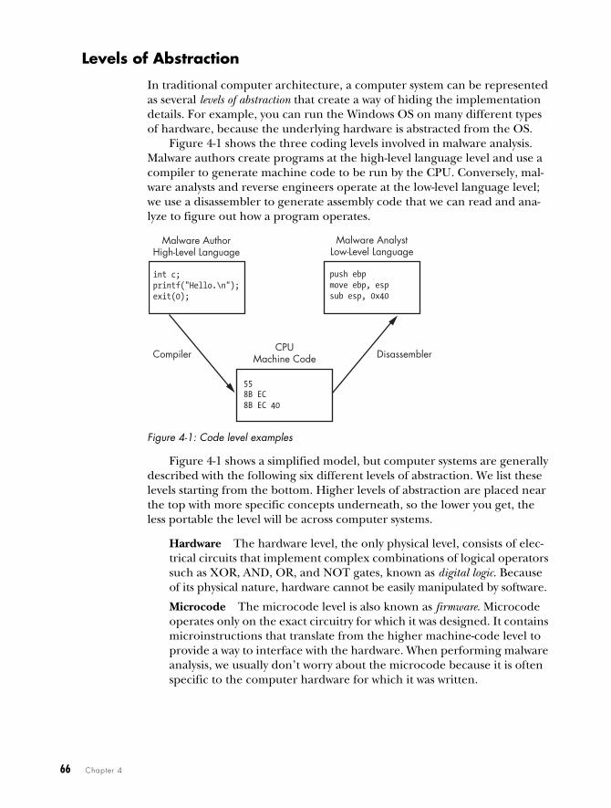
Figure 4-1 shows the three coding levels involved in malware analysis. Malware authors create programs at the high-level language level and use a compiler to generate machine code to be run by the CPU. Conversely, mal-ware analysts and reverse engineers operate at the low-level language level; we use a disassembler to generate assembly code that we can read and ana-lyze to figure out how a program operates.
Figure 4-1: Code level examples
Figure 4-1 shows a simplified model, but computer systems are generally described with the following six different levels of abstraction. We list these levels starting from the bottom. Higher levels of abstraction are placed near the top with more specific concepts underneath, so the lower you get, the less portable the level will be across computer systems.
Hardware The hardware level, the only physical level, consists of elec-trical circuits that implement complex combinations of logical operators such as XOR, AND, OR, and NOT gates, known as digital logic. Because of its physical nature, hardware cannot be easily manipulated by software.
Microcode The microcode level is also known as firmware. Microcode operates only on the exact circuitry for which it was designed. It contains microinstructions that translate from the higher machine-code level to provide a way to interface with the hardware. When performing malware analysis, we usually don’t worry about the microcode because it is often specific to the computer hardware for which it was written.
CPUMachine Code
Malware AuthorHigh-Level Language
int c;printf("Hello.\n");exit(0);
558B EC8B EC 40
Malware AnalystLow-Level Language
push ebpmove ebp, espsub esp, 0x40
Compiler Disassembler
A Crash Course in x86 Disassembly 67
Machine code The machine code level consists of opcodes, hexadecimal digits that tell the processor what you want it to do. Machine code is typi-cally implemented with several microcode instructions so that the under-lying hardware can execute the code. Machine code is created when a computer program written in a high-level language is compiled.
Low-level languages A low-level language is a human-readable version of a computer architecture’s instruction set. The most common low-level language is assembly language. Malware analysts operate at the low-level languages level because the machine code is too difficult for a human to comprehend. We use a disassembler to generate low-level language text, which consists of simple mnemonics such as mov and jmp. Many different dialects of assembly language exist, and we’ll explore each in turn.
NOTE Assembly is the highest level language that can be reliably and consistently recovered from machine code when high-level language source code is not available.
High-level languages Most computer programmers operate at the level of high-level languages. High-level languages provide strong abstraction from the machine level and make it easy to use programming logic and flow-control mechanisms. High-level languages include C, C++, and oth-ers. These languages are typically turned into machine code by a com-piler through a process known as compilation.
Interpreted languages Interpreted languages are at the top level. Many programmers use interpreted languages such as C#, Perl, .NET, and Java. The code at this level is not compiled into machine code; instead, it is translated into bytecode. Bytecode is an intermediate representation that is specific to the programming language. Bytecode executes within an interpreter, which is a program that translates bytecode into executable machine code on the fly at runtime. An interpreter provides an auto-matic level of abstraction when compared to traditional compiled code, because it can handle errors and memory management on its own, inde-pendent of the OS.
Reverse-Engineering
When malware is stored on a disk, it is typically in binary form at the machine code level. As discussed, machine code is the form of code that the computer can run quickly and efficiently. When we disassemble malware (as shown in Figure 4-1), we take the malware binary as input and generate assembly lan-guage code as output, usually with a disassembler. (Chapter 5 discusses the most popular disassembler, IDA Pro.)
Assembly language is actually a class of languages. Each assembly dialect is typically used to program a single family of microprocessors, such as x86, x64, SPARC, PowerPC, MIPS, and ARM. x86 is by far the most popular archi-tecture for PCs.
68 Chapter 4
Most 32-bit personal computers are x86, also known as Intel IA-32, and all modern 32-bit versions of Microsoft Windows are designed to run on the x86 architecture. Additionally, most AMD64 or Intel 64 architectures running Windows support x86 32-bit binaries. For this reason, most malware is com-piled for x86, which will be our focus throughout this book. (Chapter 21 cov-ers malware compiled for the Intel 64 architecture.) Here, we’ll focus on the x86 architecture aspects that come up most often during malware analysis.
NOTE For additional information about assembly, Randall Hyde’s The Art of Assembly Language, 2nd Edition (No Starch Press, 2010) is an excellent resource. Hyde’s book offers a patient introduction to x86 assembly for non-assembly programmers.
The x86 Architecture
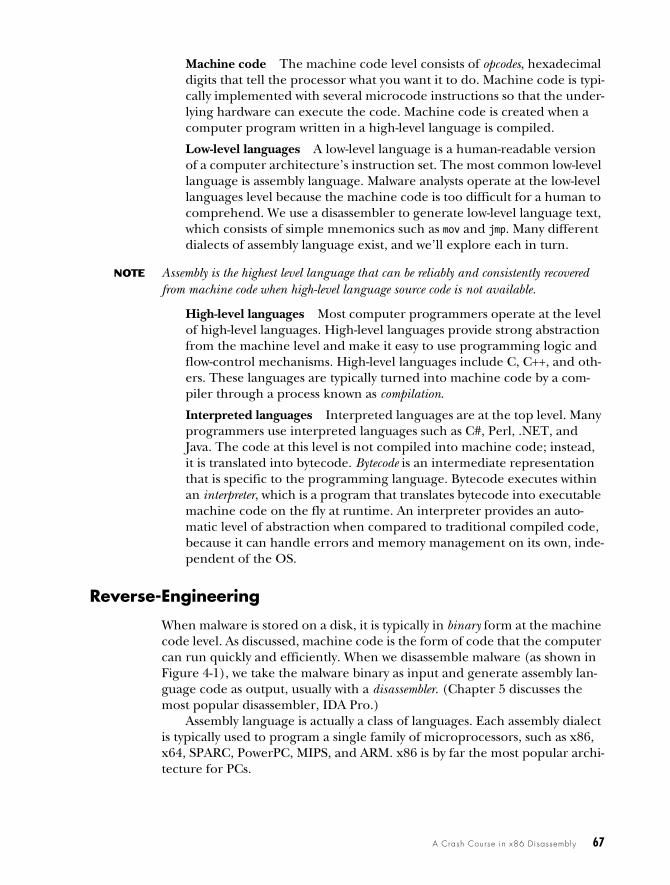
The internals of most modern computer architectures (including x86) fol-low the Von Neumann architecture, illustrated in Figure 4-2. It has three hardware components:
The central processing unit (CPU) executes code.
The main memory of the system (RAM) stores all data and code.
An input/output system (I/O) interfaces with devices such as hard drives, keyboards, and monitors.
Figure 4-2: Von Neumann architecture
As you can see in Figure 4-2, the CPU contains several components: The control unit gets instructions to execute from RAM using a register (the instruction pointer), which stores the address of the instruction to execute. Registers are the CPU’s basic data storage units and are often used to save time so that the CPU doesn’t need to access RAM. The arithmetic logic unit (ALU) executes an instruction fetched from RAM and places the results in registers or memory. The process of fetching and executing instruction after instruction is repeated as a program runs.
CPU
Registers
ALU Control Unit
Input/Output Devices
Main Memory(RAM)
A Crash Course in x86 Disassembly 69
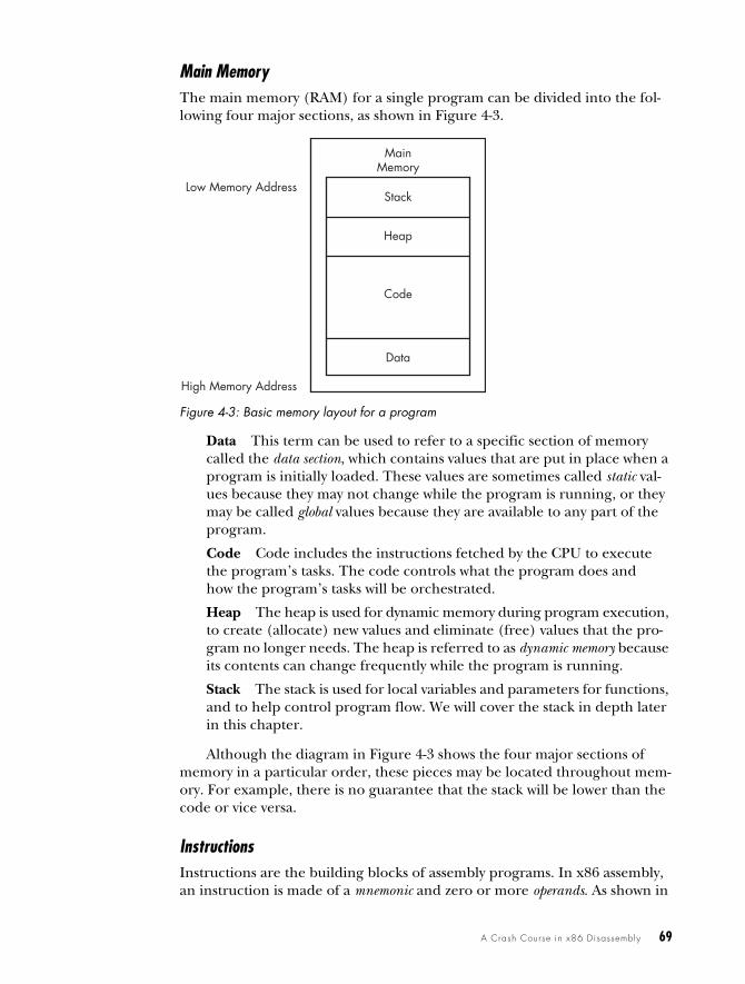
Main MemoryThe main memory (RAM) for a single program can be divided into the fol-lowing four major sections, as shown in Figure 4-3.
Figure 4-3: Basic memory layout for a program
Data This term can be used to refer to a specific section of memory called the data section, which contains values that are put in place when a program is initially loaded. These values are sometimes called static val-ues because they may not change while the program is running, or they may be called global values because they are available to any part of the program.
Code Code includes the instructions fetched by the CPU to execute the program’s tasks. The code controls what the program does and how the program’s tasks will be orchestrated.
Heap The heap is used for dynamic memory during program execution, to create (allocate) new values and eliminate (free) values that the pro-gram no longer needs. The heap is referred to as dynamic memory because its contents can change frequently while the program is running.
Stack The stack is used for local variables and parameters for functions, and to help control program flow. We will cover the stack in depth later in this chapter.
Although the diagram in Figure 4-3 shows the four major sections of memory in a particular order, these pieces may be located throughout mem-ory. For example, there is no guarantee that the stack will be lower than the code or vice versa.
InstructionsInstructions are the building blocks of assembly programs. In x86 assembly, an instruction is made of a mnemonic and zero or more operands. As shown in
MainMemory
Stack
Heap
Code
Data
High Memory Address
Low Memory Address
70 Chapter 4
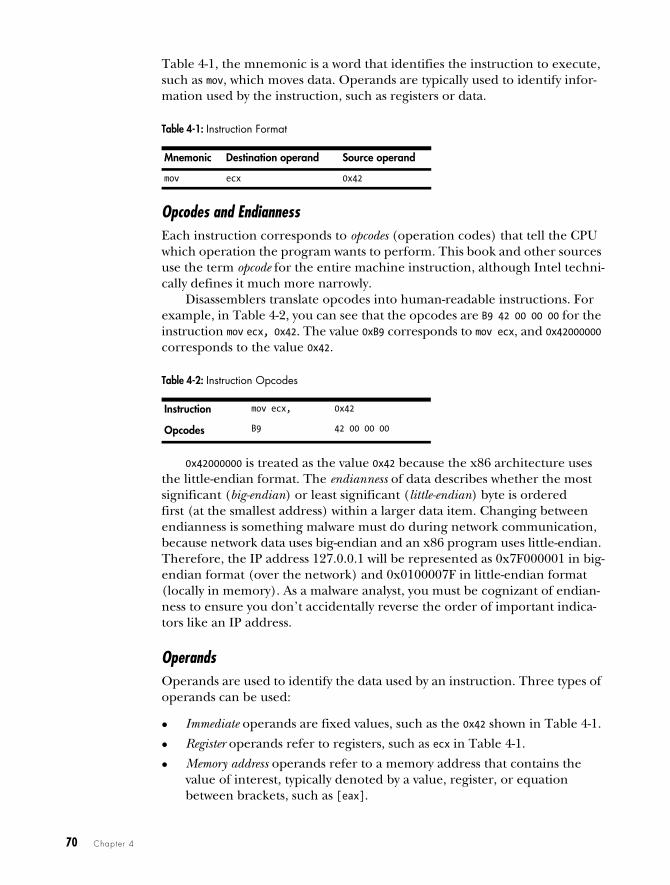
Table 4-1, the mnemonic is a word that identifies the instruction to execute, such as mov, which moves data. Operands are typically used to identify infor-mation used by the instruction, such as registers or data.
Opcodes and EndiannessEach instruction corresponds to opcodes (operation codes) that tell the CPU which operation the program wants to perform. This book and other sources use the term opcode for the entire machine instruction, although Intel techni-cally defines it much more narrowly.
Disassemblers translate opcodes into human-readable instructions. For example, in Table 4-2, you can see that the opcodes are B9 42 00 00 00 for the instruction mov ecx, 0x42. The value 0xB9 corresponds to mov ecx, and 0x42000000 corresponds to the value 0x42.
0x42000000 is treated as the value 0x42 because the x86 architecture uses the little-endian format. The endianness of data describes whether the most significant (big-endian) or least significant (little-endian) byte is ordered first (at the smallest address) within a larger data item. Changing between endianness is something malware must do during network communication, because network data uses big-endian and an x86 program uses little-endian. Therefore, the IP address 127.0.0.1 will be represented as 0x7F000001 in big-endian format (over the network) and 0x0100007F in little-endian format (locally in memory). As a malware analyst, you must be cognizant of endian-ness to ensure you don’t accidentally reverse the order of important indica-tors like an IP address.
OperandsOperands are used to identify the data used by an instruction. Three types of operands can be used:
Immediate operands are fixed values, such as the 0x42 shown in Table 4-1.
Register operands refer to registers, such as ecx in Table 4-1.
Memory address operands refer to a memory address that contains the value of interest, typically denoted by a value, register, or equation between brackets, such as [eax].
Table 4-1: Instruction Format
Mnemonic Destination operand Source operand
mov ecx 0x42
Table 4-2: Instruction Opcodes
Instruction mov ecx, 0x42
Opcodes B9 42 00 00 00
A Crash Course in x86 Disassembly 71
RegistersA register is a small amount of data storage available to the CPU, whose con-tents can be accessed more quickly than storage available elsewhere. x86 pro-cessors have a collection of registers available for use as temporary storage or workspace. Table 4-3 shows the most common x86 registers, which fall into the following four categories:
General registers are used by the CPU during execution.
Segment registers are used to track sections of memory.
Status flags are used to make decisions.
Instruction pointers are used to keep track of the next instruction to execute.
You can use Table 4-3 as a reference throughout this chapter to see how a register is categorized and broken down. The sections that follow discuss each of these register categories in depth.
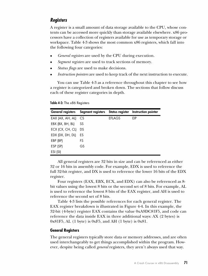
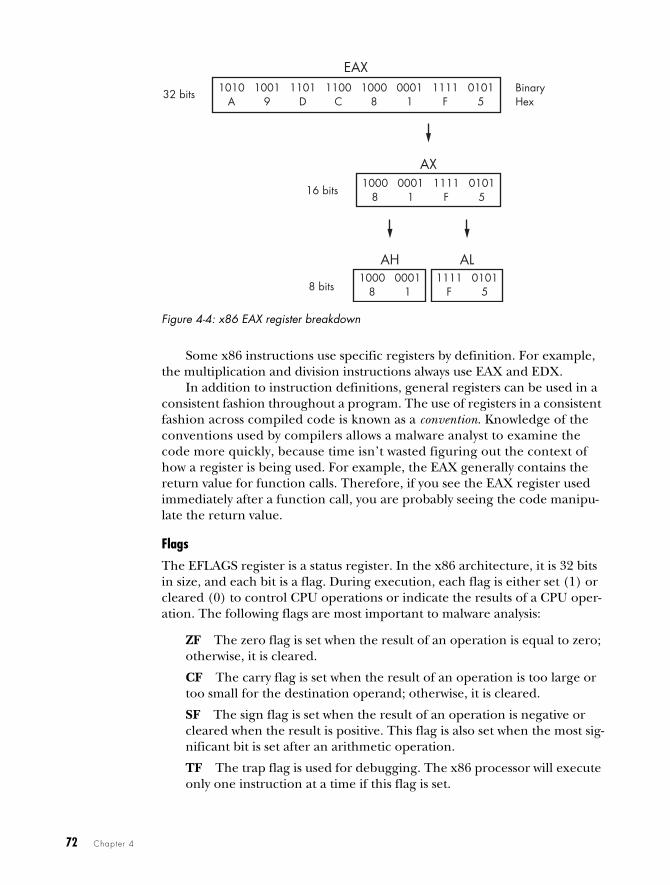
All general registers are 32 bits in size and can be referenced as either 32 or 16 bits in assembly code. For example, EDX is used to reference the full 32-bit register, and DX is used to reference the lower 16 bits of the EDX register.
Four registers (EAX, EBX, ECX, and EDX) can also be referenced as 8-bit values using the lowest 8 bits or the second set of 8 bits. For example, AL is used to reference the lowest 8 bits of the EAX register, and AH is used to reference the second set of 8 bits.
Table 4-3 lists the possible references for each general register. The EAX register breakdown is illustrated in Figure 4-4. In this example, the 32-bit (4-byte) register EAX contains the value 0xA9DC81F5, and code can reference the data inside EAX in three additional ways: AX (2 bytes) is 0x81F5, AL (1 byte) is 0xF5, and AH (1 byte) is 0x81.
General Registers
The general registers typically store data or memory addresses, and are often used interchangeably to get things accomplished within the program. How-ever, despite being called general registers, they aren’t always used that way.
Table 4-3: The x86 Registers
General registers Segment registers Status register Instruction pointer
EAX (AX, AH, AL) CS EFLAGS EIP
EBX (BX, BH, BL) SS
ECX (CX, CH, CL) DS
EDX (DX, DH, DL) ES
EBP (BP) FS
ESP (SP) GS
ESI (SI)
72 Chapter 4
Figure 4-4: x86 EAX register breakdown
Some x86 instructions use specific registers by definition. For example, the multiplication and division instructions always use EAX and EDX.
In addition to instruction definitions, general registers can be used in a consistent fashion throughout a program. The use of registers in a consistent fashion across compiled code is known as a convention. Knowledge of the conventions used by compilers allows a malware analyst to examine the code more quickly, because time isn’t wasted figuring out the context of how a register is being used. For example, the EAX generally contains the return value for function calls. Therefore, if you see the EAX register used immediately after a function call, you are probably seeing the code manipu-late the return value.
Flags
The EFLAGS register is a status register. In the x86 architecture, it is 32 bits in size, and each bit is a flag. During execution, each flag is either set (1) or cleared (0) to control CPU operations or indicate the results of a CPU oper-ation. The following flags are most important to malware analysis:
ZF The zero flag is set when the result of an operation is equal to zero; otherwise, it is cleared.
CF The carry flag is set when the result of an operation is too large or too small for the destination operand; otherwise, it is cleared.
SF The sign flag is set when the result of an operation is negative or cleared when the result is positive. This flag is also set when the most sig-nificant bit is set after an arithmetic operation.
TF The trap flag is used for debugging. The x86 processor will execute only one instruction at a time if this flag is set.
EAX1010 1001 1101 1100 1000 0001 1111 0101
A 9 D C 8 1 F 532 bits
AX1000 0001 1111 0101
8 1 F 516 bits
AH1000 0001
8 1
AL1111 0101
F 58 bits
BinaryHex
A Crash Course in x86 Disassembly 73
NOTE For details on all available flags, see Volume 1 of the Intel 64 and IA-32 Architec-tures Software Developer’s Manuals, discussed at the end of this chapter.
EIP, the Instruction Pointer
In x86 architecture, EIP, also known as the instruction pointer or program counter, is a register that contains the memory address of the next instruction to be executed for a program. EIP’s only purpose is to tell the processor what to do next.
NOTE When EIP is corrupted (that is, it points to a memory address that does not contain legitimate program code), the CPU will not be able to fetch legitimate code to execute, so the program running at the time will likely crash. When you control EIP, you can con-trol what is executed by the CPU, which is why attackers attempt to gain control of EIP through exploitation. Generally, attackers must have attack code in memory and then change EIP to point to that code to exploit a system.
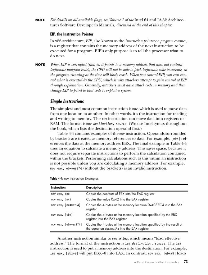
Simple InstructionsThe simplest and most common instruction is mov, which is used to move data from one location to another. In other words, it’s the instruction for reading and writing to memory. The mov instruction can move data into registers or RAM. The format is mov destination, source. (We use Intel syntax throughout the book, which lists the destination operand first.)
Table 4-4 contains examples of the mov instruction. Operands surrounded by brackets are treated as memory references to data. For example, [ebx] ref-erences the data at the memory address EBX. The final example in Table 4-4 uses an equation to calculate a memory address. This saves space, because it does not require separate instructions to perform the calculation contained within the brackets. Performing calculations such as this within an instruction is not possible unless you are calculating a memory address. For example, mov eax, ebx+esi*4 (without the brackets) is an invalid instruction.
Another instruction similar to mov is lea, which means “load effective address.” The format of the instruction is lea destination, source. The lea instruction is used to put a memory address into the destination. For example, lea eax, [ebx+8] will put EBX+8 into EAX. In contrast, mov eax, [ebx+8] loads
Table 4-4: mov Instruction Examples
Instruction Description
mov eax, ebx Copies the contents of EBX into the EAX register
mov eax, 0x42 Copies the value 0x42 into the EAX register
mov eax, [0x4037C4] Copies the 4 bytes at the memory location 0x4037C4 into the EAX register
mov eax, [ebx] Copies the 4 bytes at the memory location specified by the EBX register into the EAX register
mov eax, [ebx+esi*4] Copies the 4 bytes at the memory location specified by the result of the equation ebx+esi*4 into the EAX register
74 Chapter 4
the data at the memory address specified by EBX+8. Therefore, lea eax, [ebx+8] would be the same as mov eax, ebx+8; however, a mov instruction like that is invalid.
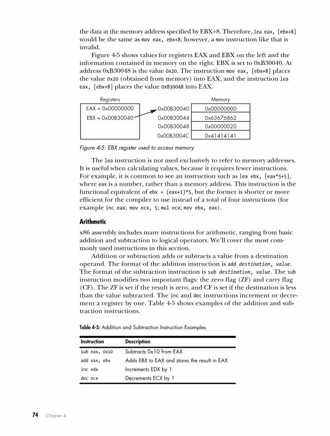
Figure 4-5 shows values for registers EAX and EBX on the left and the information contained in memory on the right. EBX is set to 0xB30040. At address 0xB30048 is the value 0x20. The instruction mov eax, [ebx+8] places the value 0x20 (obtained from memory) into EAX, and the instruction lea eax, [ebx+8] places the value 0xB30048 into EAX.
Figure 4-5: EBX register used to access memory
The lea instruction is not used exclusively to refer to memory addresses. It is useful when calculating values, because it requires fewer instructions. For example, it is common to see an instruction such as lea ebx, [eax*5+5], where eax is a number, rather than a memory address. This instruction is the functional equivalent of ebx = (eax+1)*5, but the former is shorter or more efficient for the compiler to use instead of a total of four instructions (for example inc eax; mov ecx, 5; mul ecx; mov ebx, eax).
Arithmetic
x86 assembly includes many instructions for arithmetic, ranging from basic addition and subtraction to logical operators. We’ll cover the most com-monly used instructions in this section.
Addition or subtraction adds or subtracts a value from a destination operand. The format of the addition instruction is add destination, value. The format of the subtraction instruction is sub destination, value. The sub instruction modifies two important flags: the zero flag (ZF) and carry flag (CF). The ZF is set if the result is zero, and CF is set if the destination is less than the value subtracted. The inc and dec instructions increment or decre-ment a register by one. Table 4-5 shows examples of the addition and sub-traction instructions.
Table 4-5: Addition and Subtraction Instruction Examples
Instruction Description
sub eax, 0x10 Subtracts 0x10 from EAX
add eax, ebx Adds EBX to EAX and stores the result in EAX
inc edx Increments EDX by 1
dec ecx Decrements ECX by 1
MemoryRegisters
EAX = 0x00000000 0x00000000
0x63676862
0x00000020
0x41414141
0x00B30040
0x00B30044
0x00B30048
0x00B3004C
EBX = 0x00B30040
A Crash Course in x86 Disassembly 75
Multiplication and division both act on a predefined register, so the command is simply the instruction, plus the value that the register will be multiplied or divided by. The format of the mul instruction is mul value. Simi-larly, the format of div instruction is div value. The assignment of the register on which a mul or div instruction acts can occur many instructions earlier, so you might need to search through a program to find it.
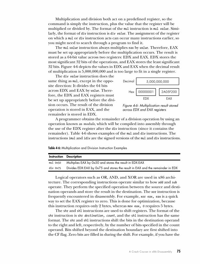
The mul value instruction always multiplies eax by value. Therefore, EAX must be set up appropriately before the multiplication occurs. The result is stored as a 64-bit value across two registers: EDX and EAX. EDX stores the most significant 32 bits of the operations, and EAX stores the least significant 32 bits. Figure 4-6 depicts the values in EDX and EAX when the decimal result of multiplication is 5,000,000,000 and is too large to fit in a single register.
A programmer obtains the remainder of a division operation by using an operation known as modulo, which will be compiled into assembly through the use of the EDX register after the div instruction (since it contains the remainder). Table 4-6 shows examples of the mul and div instructions. The instructions imul and idiv are the signed versions of the mul and div instructions.
Logical operators such as OR, AND, and XOR are used in x86 archi-tecture. The corresponding instructions operate similar to how add and sub operate. They perform the specified operation between the source and desti-nation operands and store the result in the destination. The xor instruction is frequently encountered in disassembly. For example, xor eax, eax is a quick way to set the EAX register to zero. This is done for optimization, because this instruction requires only 2 bytes, whereas mov eax, 0 requires 5 bytes.
The shr and shl instructions are used to shift registers. The format of the shr instruction is shr destination, count, and the shl instruction has the same format. The shr and shl instructions shift the bits in the destination operand to the right and left, respectively, by the number of bits specified in the count operand. Bits shifted beyond the destination boundary are first shifted into the CF flag. Zero bits are filled in during the shift. For example, if you have the
The div value instruction does the same thing as mul, except in the oppo-site direction: It divides the 64 bits across EDX and EAX by value. There-fore, the EDX and EAX registers must be set up appropriately before the divi-sion occurs. The result of the division operation is stored in EAX, and the remainder is stored in EDX.
Figure 4-6: Multiplication result stored across EDX and EAX registers
Table 4-6: Multiplication and Division Instruction Examples
Instruction Description
mul 0x50 Multiplies EAX by 0x50 and stores the result in EDX:EAX
div 0x75 Divides EDX:EAX by 0x75 and stores the result in EAX and the remainder in EDX
5,000,000,000
00000001 2A05F200
EDX EAX
Decimal
Hex
76 Chapter 4
binary value 1000 and shift it right by 1, the result is 0100. At the end of the shift instruction, the CF flag contains the last bit shifted out of the destina-tion operand.
The rotation instructions, ror and rol, are similar to the shift instructions, except the shifted bits that “fall off” with the shift operation are rotated to the other end. In other words, during a right rotation (ror) the least signifi-cant bits are rotated to the most significant position. Left rotation (rol) is the exact opposite. Table 4-7 displays examples of these instructions.
Shifting is often used in place of multiplication as an optimization. Shift-ing is simpler and faster than multiplication, because you don’t need to set up registers and move data around, as you do for multiplication. The shl eax, 1 instruction computes the same result as multiplying EAX by two. Shifting to the left two bit positions multiplies the operand by four, and shifting to the left three bit positions multiplies the operand by eight. Shifting an operand to the left n bits multiplies it by 2n.
During malware analysis, if you encounter a function containing only the instructions xor, or, and, shl, ror, shr, or rol repeatedly and seemingly ran-domly, you have probably encountered an encryption or compression func-tion. Don’t get bogged down trying to analyze each instruction unless you really need to do so. Instead, your best bet in most cases is to mark this as an encryption routine and move on.
NOP
The final simple instruction, nop, does nothing. When it’s issued, execution simply proceeds to the next instruction. The instruction nop is actually a pseudonym for xhcg eax, eax, but since exchanging EAX with itself does nothing, it is popularly referred to as NOP (no operation).
The opcode for this instruction is 0x90. It is commonly used in a NOP sled for buffer overflow attacks, when attackers don’t have perfect control of their exploitation. It provides execution padding, which reduces the risk that the malicious shellcode will start executing in the middle, and therefore mal-function. We discuss nop sleds and shellcode in depth in Chapter 19.
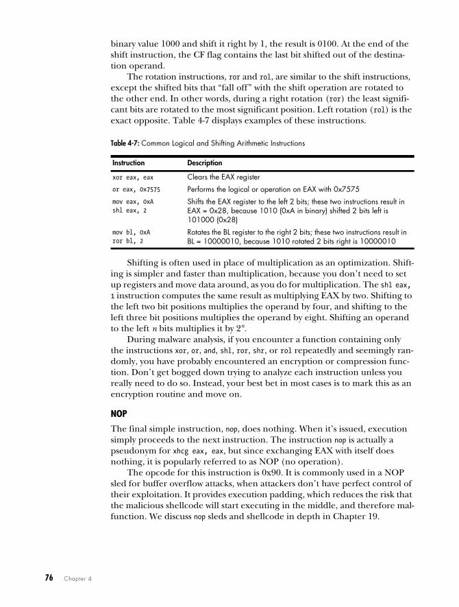
Table 4-7: Common Logical and Shifting Arithmetic Instructions
Instruction Description
xor eax, eax Clears the EAX register
or eax, 0x7575 Performs the logical or operation on EAX with 0x7575
mov eax, 0xAshl eax, 2
Shifts the EAX register to the left 2 bits; these two instructions result in EAX = 0x28, because 1010 (0xA in binary) shifted 2 bits left is 101000 (0x28)
mov bl, 0xAror bl, 2
Rotates the BL register to the right 2 bits; these two instructions result in BL = 10000010, because 1010 rotated 2 bits right is 10000010
A Crash Course in x86 Disassembly 77
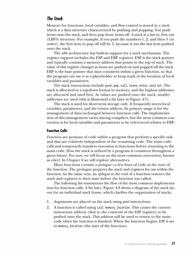
The StackMemory for functions, local variables, and flow control is stored in a stack, which is a data structure characterized by pushing and popping. You push items onto the stack, and then pop those items off. A stack is a last in, first out (LIFO) structure. For example, if you push the numbers 1, 2, and then 3 (in order), the first item to pop off will be 3, because it was the last item pushed onto the stack.
The x86 architecture has built-in support for a stack mechanism. The register support includes the ESP and EBP registers. ESP is the stack pointer and typically contains a memory address that points to the top of stack. The value of this register changes as items are pushed on and popped off the stack. EBP is the base pointer that stays consistent within a given function, so that the program can use it as a placeholder to keep track of the location of local variables and parameters.
The stack instructions include push, pop, call, leave, enter, and ret. The stack is allocated in a top-down format in memory, and the highest addresses are allocated and used first. As values are pushed onto the stack, smaller addresses are used (this is illustrated a bit later in Figure 4-7).
The stack is used for short-term storage only. It frequently stores local variables, parameters, and the return address. Its primary usage is for the management of data exchanged between function calls. The implementa-tion of this management varies among compilers, but the most common con-vention is for local variables and parameters to be referenced relative to EBP.
Function Calls
Functions are portions of code within a program that perform a specific task and that are relatively independent of the remaining code. The main code calls and temporarily transfers execution to functions before returning to the main code. How the stack is utilized by a program is consistent throughout a given binary. For now, we will focus on the most common convention, known as cdecl. In Chapter 6 we will explore alternatives.
Many functions contain a prologue—a few lines of code at the start of the function. The prologue prepares the stack and registers for use within the function. In the same vein, an epilogue at the end of a function restores the stack and registers to their state before the function was called.
The following list summarizes the flow of the most common implementa-tion for function calls. A bit later, Figure 4-8 shows a diagram of the stack lay-out for an individual stack frame, which clarifies the organization of stacks.
1. Arguments are placed on the stack using push instructions.
2. A function is called using call memory_location. This causes the current instruction address (that is, the contents of the EIP register) to be pushed onto the stack. This address will be used to return to the main code when the function is finished. When the function begins, EIP is set to memory_location (the start of the function).
78 Chapter 4
3. Through the use of a function prologue, space is allocated on the stack for local variables and EBP (the base pointer) is pushed onto the stack. This is done to save EBP for the calling function.
4. The function performs its work.
5. Through the use of a function epilogue, the stack is restored. ESP is adjusted to free the local variables, and EBP is restored so that the call-ing function can address its variables properly. The leave instruction can be used as an epilogue because it sets ESP to equal EBP and pops EBP off the stack.
6. The function returns by calling the ret instruction. This pops the return address off the stack and into EIP, so that the program will continue exe-cuting from where the original call was made.
7. The stack is adjusted to remove the arguments that were sent, unless they’ll be used again later.
Stack Layout
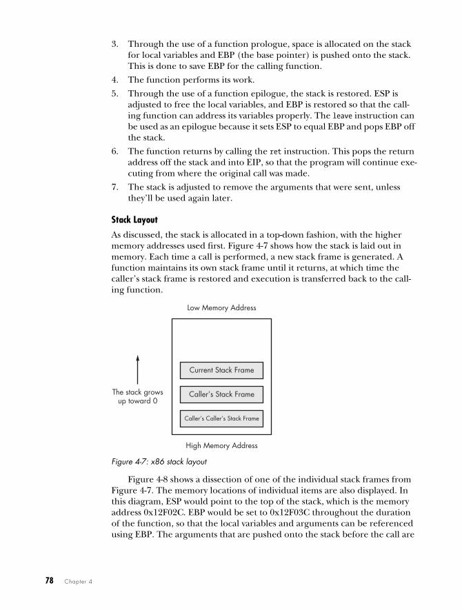
As discussed, the stack is allocated in a top-down fashion, with the higher memory addresses used first. Figure 4-7 shows how the stack is laid out in memory. Each time a call is performed, a new stack frame is generated. A function maintains its own stack frame until it returns, at which time the caller’s stack frame is restored and execution is transferred back to the call-ing function.
Figure 4-7: x86 stack layout
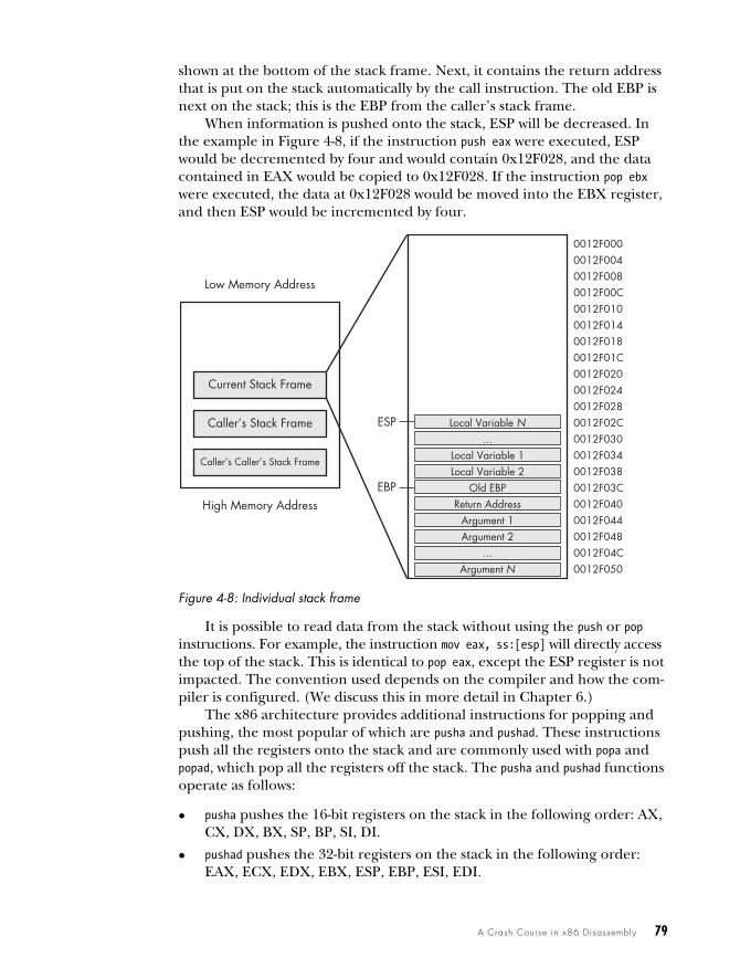
Figure 4-8 shows a dissection of one of the individual stack frames from Figure 4-7. The memory locations of individual items are also displayed. In this diagram, ESP would point to the top of the stack, which is the memory address 0x12F02C. EBP would be set to 0x12F03C throughout the duration of the function, so that the local variables and arguments can be referenced using EBP. The arguments that are pushed onto the stack before the call are
Low Memory Address
Current Stack Frame
Caller’s Stack Frame
Caller’s Caller’s Stack Frame
High Memory Address
The stack growsup toward 0
A Crash Course in x86 Disassembly 79
shown at the bottom of the stack frame. Next, it contains the return address that is put on the stack automatically by the call instruction. The old EBP is next on the stack; this is the EBP from the caller’s stack frame.
When information is pushed onto the stack, ESP will be decreased. In the example in Figure 4-8, if the instruction push eax were executed, ESP would be decremented by four and would contain 0x12F028, and the data contained in EAX would be copied to 0x12F028. If the instruction pop ebx were executed, the data at 0x12F028 would be moved into the EBX register, and then ESP would be incremented by four.
Figure 4-8: Individual stack frame
It is possible to read data from the stack without using the push or pop instructions. For example, the instruction mov eax, ss:[esp] will directly access the top of the stack. This is identical to pop eax, except the ESP register is not impacted. The convention used depends on the compiler and how the com-piler is configured. (We discuss this in more detail in Chapter 6.)
The x86 architecture provides additional instructions for popping and pushing, the most popular of which are pusha and pushad. These instructions push all the registers onto the stack and are commonly used with popa and popad, which pop all the registers off the stack. The pusha and pushad functions operate as follows:
pusha pushes the 16-bit registers on the stack in the following order: AX, CX, DX, BX, SP, BP, SI, DI.
pushad pushes the 32-bit registers on the stack in the following order: EAX, ECX, EDX, EBX, ESP, EBP, ESI, EDI.
Low Memory Address
Current Stack Frame
Caller’s Stack Frame
Caller’s Caller’s Stack Frame
High Memory Address
0012F0000012F0040012F0080012F00C0012F0100012F0140012F0180012F01C0012F0200012F0240012F0280012F02C0012F0300012F0340012F0380012F03C0012F0400012F0440012F0480012F04C0012F050
Local Variable N
Local Variable 2Local Variable 1
Old EBPReturn Address
Argument 1Argument 2
...
...Argument N
ESP
EBP
80 Chapter 4
These instructions are typically encountered in shellcode when someone wants to save the current state of the registers to the stack so that they can be restored at a later time. Compilers rarely use these instructions, so seeing them often indicates someone hand-coded assembly and/or shellcode.
ConditionalsAll programming languages have the ability to make comparisons and make decisions based on those comparisons. Conditionals are instructions that per-form the comparison.
The two most popular conditional instructions are test and cmp. The test instruction is identical to the and instruction; however, the operands involved are not modified by the instruction. The test instruction only sets the flags. The zero flag (ZF) is typically the flag of interest after the test instruction. A test of something against itself is often used to check for NULL values. An example of this is test eax, eax. You could also compare EAX to zero, but test eax, eax uses fewer bytes and fewer CPU cycles.
The cmp instruction is identical to the sub instruction; however, the oper-ands are not affected. The cmp instruction is used only to set the flags. The zero flag and carry flag (CF) may be changed as a result of the cmp instruc-tion. Table 4-8 shows how the cmp instruction impacts the flags.
BranchingA branch is a sequence of code that is conditionally executed depending on the flow of the program. The term branching is used to describe the control flow through the branches of a program.
The most popular way branching occurs is with jump instructions. An extensive set of jump instructions is used, of which the jmp instruction is the simplest. The format jmp location causes the next instruction executed to be the one specified by the jmp. This is known as an unconditional jump, because execution will always transfer to the target location. This simple jump will not satisfy all of your branching needs. For example, the logical equivalent to an if statement isn’t possible with a jmp. There is no if statement in assembly code. This is where conditional jumps come in.
Conditional jumps use the flags to determine whether to jump or to proceed to the next instruction. More than 30 different types of conditional jumps can be used, but only a small set of them is commonly encountered.
Table 4-8: cmp Instruction and Flags
cmp dst, src ZF CF
dst = src 1 0
dst < src 0 1
dst > src 0 0
A Crash Course in x86 Disassembly 81
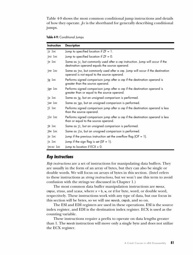
Table 4-9 shows the most common conditional jump instructions and details of how they operate. Jcc is the shorthand for generally describing conditional jumps.
Rep InstructionsRep instructions are a set of instructions for manipulating data buffers. They are usually in the form of an array of bytes, but they can also be single or double words. We will focus on arrays of bytes in this section. (Intel refers to these instructions as string instructions, but we won’t use this term to avoid confusion with the strings we discussed in Chapter 1.)
The most common data buffer manipulation instructions are movsx, cmpsx, stosx, and scasx, where x = b, w, or d for byte, word, or double word, respectively. These instructions work with any type of data, but our focus in this section will be bytes, so we will use movsb, cmpsb, and so on.
The ESI and EDI registers are used in these operations. ESI is the source index register, and EDI is the destination index register. ECX is used as the counting variable.
These instructions require a prefix to operate on data lengths greater than 1. The movsb instruction will move only a single byte and does not utilize the ECX register.
Table 4-9: Conditional Jumps
Instruction Description
jz loc Jump to specified location if ZF = 1.
jnz loc Jump to specified location if ZF = 0.
je loc Same as jz, but commonly used after a cmp instruction. Jump will occur if the destination operand equals the source operand.
jne loc Same as jnz, but commonly used after a cmp. Jump will occur if the destination operand is not equal to the source operand.
jg loc Performs signed comparison jump after a cmp if the destination operand is greater than the source operand.
jge loc Performs signed comparison jump after a cmp if the destination operand is greater than or equal to the source operand.
ja loc Same as jg, but an unsigned comparison is performed.
jae loc Same as jge, but an unsigned comparison is performed.
jl loc Performs signed comparison jump after a cmp if the destination operand is less than the source operand.
jle loc Performs signed comparison jump after a cmp if the destination operand is less than or equal to the source operand.
jb loc Same as jl, but an unsigned comparison is performed.
jbe loc Same as jle, but an unsigned comparison is performed.
jo loc Jump if the previous instruction set the overflow flag (OF = 1).
js loc Jump if the sign flag is set (SF = 1).
jecxz loc Jump to location if ECX = 0.
82 Chapter 4
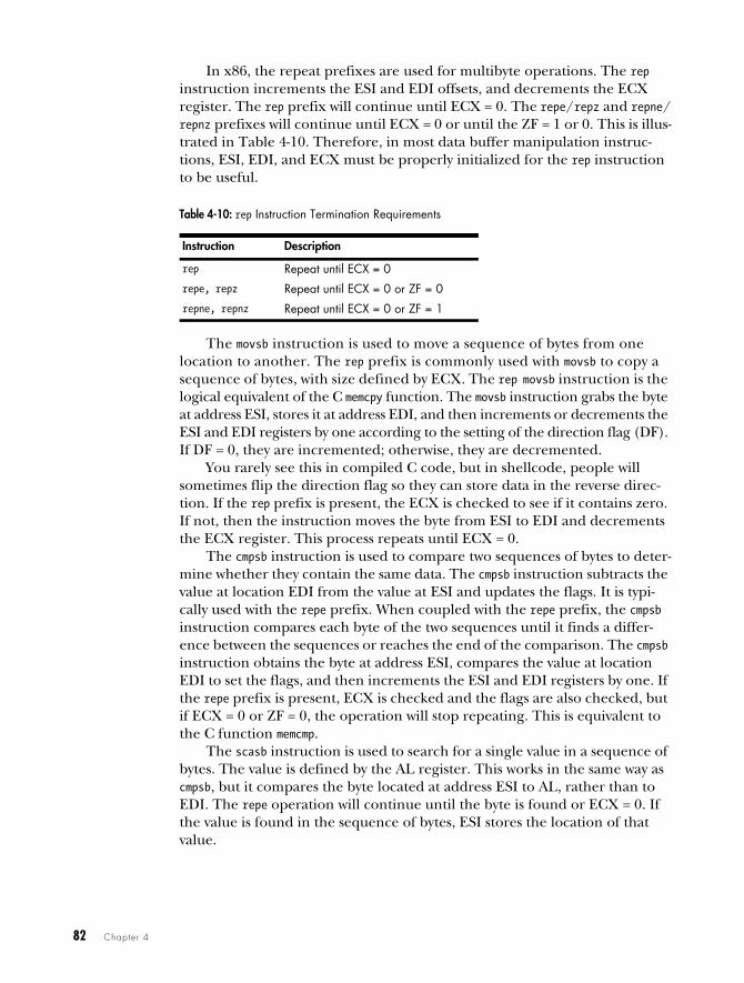
In x86, the repeat prefixes are used for multibyte operations. The rep instruction increments the ESI and EDI offsets, and decrements the ECX register. The rep prefix will continue until ECX = 0. The repe/repz and repne/repnz prefixes will continue until ECX = 0 or until the ZF = 1 or 0. This is illus-trated in Table 4-10. Therefore, in most data buffer manipulation instruc-tions, ESI, EDI, and ECX must be properly initialized for the rep instruction to be useful.
The movsb instruction is used to move a sequence of bytes from one location to another. The rep prefix is commonly used with movsb to copy a sequence of bytes, with size defined by ECX. The rep movsb instruction is the logical equivalent of the C memcpy function. The movsb instruction grabs the byte at address ESI, stores it at address EDI, and then increments or decrements the ESI and EDI registers by one according to the setting of the direction flag (DF). If DF = 0, they are incremented; otherwise, they are decremented.
You rarely see this in compiled C code, but in shellcode, people will sometimes flip the direction flag so they can store data in the reverse direc-tion. If the rep prefix is present, the ECX is checked to see if it contains zero. If not, then the instruction moves the byte from ESI to EDI and decrements the ECX register. This process repeats until ECX = 0.
The cmpsb instruction is used to compare two sequences of bytes to deter-mine whether they contain the same data. The cmpsb instruction subtracts the value at location EDI from the value at ESI and updates the flags. It is typi-cally used with the repe prefix. When coupled with the repe prefix, the cmpsb instruction compares each byte of the two sequences until it finds a differ-ence between the sequences or reaches the end of the comparison. The cmpsb instruction obtains the byte at address ESI, compares the value at location EDI to set the flags, and then increments the ESI and EDI registers by one. If the repe prefix is present, ECX is checked and the flags are also checked, but if ECX = 0 or ZF = 0, the operation will stop repeating. This is equivalent to the C function memcmp.
The scasb instruction is used to search for a single value in a sequence of bytes. The value is defined by the AL register. This works in the same way as cmpsb, but it compares the byte located at address ESI to AL, rather than to EDI. The repe operation will continue until the byte is found or ECX = 0. If the value is found in the sequence of bytes, ESI stores the location of that value.
Table 4-10: rep Instruction Termination Requirements
Instruction Description
rep Repeat until ECX = 0
repe, repz Repeat until ECX = 0 or ZF = 0
repne, repnz Repeat until ECX = 0 or ZF = 1
A Crash Course in x86 Disassembly 83
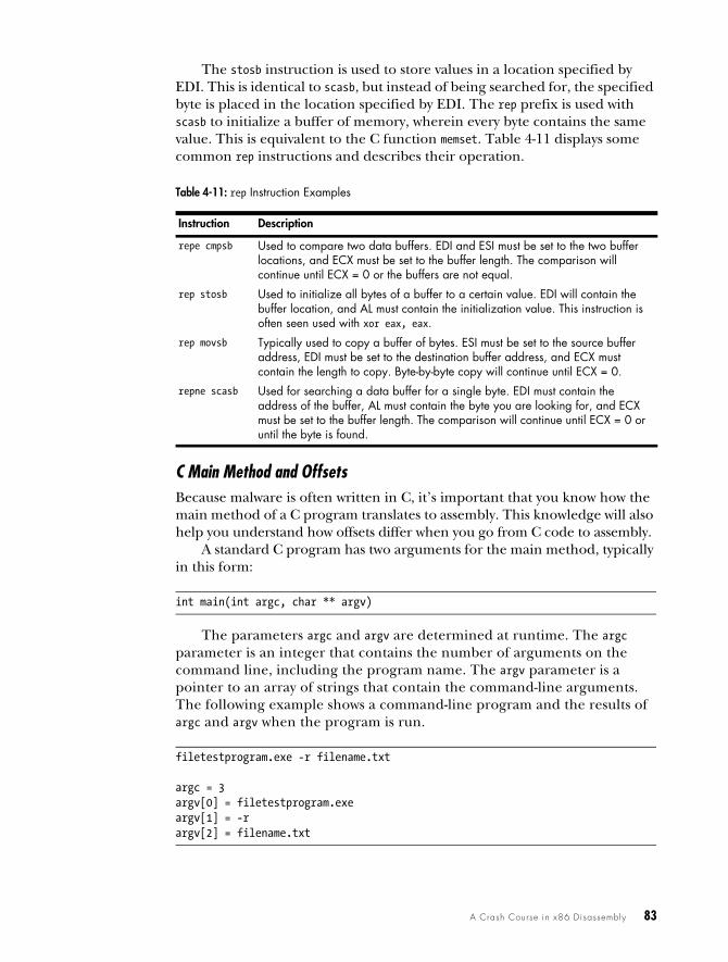
The stosb instruction is used to store values in a location specified by EDI. This is identical to scasb, but instead of being searched for, the specified byte is placed in the location specified by EDI. The rep prefix is used with scasb to initialize a buffer of memory, wherein every byte contains the same value. This is equivalent to the C function memset. Table 4-11 displays some common rep instructions and describes their operation.
C Main Method and OffsetsBecause malware is often written in C, it’s important that you know how the main method of a C program translates to assembly. This knowledge will also help you understand how offsets differ when you go from C code to assembly.
A standard C program has two arguments for the main method, typically in this form:
int main(int argc, char ** argv)
The parameters argc and argv are determined at runtime. The argc parameter is an integer that contains the number of arguments on the command line, including the program name. The argv parameter is a pointer to an array of strings that contain the command-line arguments. The following example shows a command-line program and the results of argc and argv when the program is run.
filetestprogram.exe -r filename.txt
argc = 3argv[0] = filetestprogram.exeargv[1] = -rargv[2] = filename.txt
Table 4-11: rep Instruction Examples
Instruction Description
repe cmpsb Used to compare two data buffers. EDI and ESI must be set to the two buffer locations, and ECX must be set to the buffer length. The comparison will continue until ECX = 0 or the buffers are not equal.
rep stosb Used to initialize all bytes of a buffer to a certain value. EDI will contain the buffer location, and AL must contain the initialization value. This instruction is often seen used with xor eax, eax.
rep movsb Typically used to copy a buffer of bytes. ESI must be set to the source buffer address, EDI must be set to the destination buffer address, and ECX must contain the length to copy. Byte-by-byte copy will continue until ECX = 0.
repne scasb Used for searching a data buffer for a single byte. EDI must contain the address of the buffer, AL must contain the byte you are looking for, and ECX must be set to the buffer length. The comparison will continue until ECX = 0 or until the byte is found.
84 Chapter 4
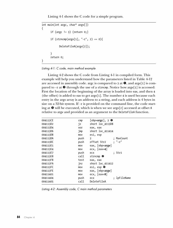
Listing 4-1 shows the C code for a simple program.
int main(int argc, char* argv[]){ if (argc != 3) {return 0;}
if (strncmp(argv[1], "-r", 2) == 0){
DeleteFileA(argv[2]);
} return 0;}
Listing 4-1: C code, main method example
Listing 4-2 shows the C code from Listing 4-1 in compiled form. This example will help you understand how the parameters listed in Table 4-12 are accessed in assembly code. argc is compared to 3 at , and argv[1] is com-pared to -r at through the use of a strncmp. Notice how argv[1] is accessed: First the location of the beginning of the array is loaded into eax, and then 4 (the offset) is added to eax to get argv[1]. The number 4 is used because each entry in the argv array is an address to a string, and each address is 4 bytes in size on a 32-bit system. If -r is provided on the command line, the code start-ing at will be executed, which is when we see argv[2] accessed at offset 8 relative to argv and provided as an argument to the DeleteFileA function.
004113CE cmp [ebp+argc], 3 004113D2 jz short loc_4113D8004113D4 xor eax, eax004113D6 jmp short loc_411414004113D8 mov esi, esp004113DA push 2 ; MaxCount004113DC push offset Str2 ; "-r"004113E1 mov eax, [ebp+argv]004113E4 mov ecx, [eax+4]004113E7 push ecx ; Str1004113E8 call strncmp 004113F8 test eax, eax004113FA jnz short loc_411412004113FC mov esi, esp 004113FE mov eax, [ebp+argv]00411401 mov ecx, [eax+8]00411404 push ecx ; lpFileName00411405 call DeleteFileA
Listing 4-2: Assembly code, C main method parameters
A Crash Course in x86 Disassembly 85
More Information: Intel x86 Architecture ManualsWhat if you encounter an instruction you have never seen before? If you can’t find your answer with a Google search, you can download the complete x86 architecture manuals from Intel at http://www.intel.com/products/processor/manuals/index.htm. This set includes the following:
Volume 1: Basic ArchitectureThis manual describes the architecture and programming environment. It is useful for helping you understand how memory works, including registers, memory layout, addressing, and the stack. This manual also contains details about general instruction groups.
Volume 2A: Instruction Set Reference, A–M, and Volume 2B: Instruction Set Refer-ence, N–Z
These are the most useful manuals for the malware analyst. They alpha-betize the entire instruction set and discuss every aspect of each instruc-tion, including the format of the instruction, opcode information, and how the instruction impacts the system.
Volume 3A: System Programming Guide, Part 1, and Volume 3B: System Program-ming Guide, Part 2
In addition to general-purpose registers, x86 has many special-purpose registers and instructions that impact execution and support the OS, including debugging, memory management, protection, task manage-ment, interrupt and exception handling, multiprocessor support, and more. If you encounter special-purpose registers, refer to the System Programming Guide to see how they impact execution.
Optimization Reference ManualThis manual describes code-optimization techniques for applications. It offers additional insight into the code generated by compilers and has many good examples of how instructions can be used in unconven-tional ways.
Conclusion
A working knowledge of assembly and the disassembly process is key to becoming a successful malware analyst. This chapter has laid the foundation for important x86 concepts that you will encounter when disassembling mal-ware. Use it as a reference if you encounter unfamiliar instructions or regis-ters while performing analysis throughout the book.
Chapter 6 builds on this chapter to give you a well-rounded assembly foundation. But the only real way to get good at disassembly is to practice. In the next chapter, we’ll take a look at IDA Pro, a tool that will greatly aid your analysis of disassembly.