Embed Size (px)
Citation preview
A
Cq ÿ
WALTER EDWARO BLYTHE
àdioCa f t f.,he
Professional-Serviceman-Radiotrician
a n
25 Cen l
HUGO GERNSBACK Editor
Men who. have m.-1t_ l ad 1(1 : Reginald ,-9.Fessenden
Thousands of Positions
Open Right Now
at
Salaries Ranging
UP to $20000 Per WEEK for MOTION PICTURE SOUND Engineers
WE are in contact with chain theatres and manufacturers of
Sound equipment who desire the services of competent sound men as engineers, projectionists, instal- lation and service men. Our em- ployment department will assist you in making a profitable con- nection free of charge.
GUARANTEE
Our guarantee insures you that if you enroll as one of our students and take advantage of the many opportunities that your member- ship entitles you to your increased income will pay the tuition of the course many times. We uncon- ditionally guarantee that if for any reason you are dissatisfied (you being the judge) we will re- fund every cent you have paid.
Due to the fact that (radio and sound are so closely allied, men with radio experience are the most adaptable.
POLICY Our course on Sound Projection which is prepared by the most eminent authorities on Electrical Acoustics will qualify you for a Profession whose place in the engineering world is second to none. All of the available knowl- edge of the art and the underlying fundamental principles of sound is given to you in an everyday, plain -talk language, as well as two weeks' practical training in the operation, servicing and instal- lation of Sound Equipment.
DEMAND In the 20,000 theatres throughout the United States and Canada,
which now employ approximately 50,000 projectionists, it is esti- mated that a very small per cent of this number are qualified to fill the position as Sound operators. Many thouands of new men will have to be taken into this field as fast as the many thousand unwired theatres are wired for sound as the additions of sound doubles the number of operators required. This condition will create many thousands of positions at salaries up to $200.00 per week. The tuition for these courses is very reasonable and is payable in easy installments as you study. Also you have the added conve- nience of studying at home in your spare time. Fill out and mail the coupon below today for special scholarship proposition.
Mail Coupon for Free Information
PROJECTIONIST r------------ - -- --, PROJECTIONIST SOUND INSTITUTE,
SOUND'
P. 0. Box No. 28, Easton, Pa. RC -1 I
I
INSTITUTE i 1
' City State J
F. A. JEWELL, Gen. Mgr.
P. O. Box No. 28, Easton, Pa.
Gentlemen: Please send me, by return mail, full details of your Special Scholarship Prop
osition on Sound Projection. I Name I
Address I
January, 10311
1 i R:1 DIO-CR AFT
yf __ Chlc$alvvR'p StocK St or*
t.ita st ^' CI,. cv n,Ill S 00 t';' On every page of this big catalog for 1930 you will find radio
merchandise of unusual interest -priced at the lowest whole- sale quotations. No radio enthusiast or dealer can afford to be without it The latest radio devices and improvements are illustrated - sets, accessories, parts and kits -at price- saving reductions that spell the buyer's opportunity. Astounding offerings in new, humless, Screen Grid A. C. all- electric and battery oper- ated sets; beautiful and artistic consoles; dynamic speakers of great vol- ume and rich tone; and everything considered standard in accessories, parts and kits.
The startling values listed in this Catalog are made possible by our tremendous buying power, low cost of operation and willingness to take a conservative profit. Quick ser-
vice, expert cooperation and unusual satisfaction are assured to every customer.
Don't fall to get this FREE wonder book. It will save
you big money. Mail the Coupon Today!
FREE, CREEK GRID CATA LO G
I Chicago Salvage Stock Store
Dept. 130 t 509 So. State St., Chicago, w'
Kindly send me (free of charg e and postpaid) ain).
1 your new 148 -page Book of Radio ins.
.............. gddress........ City ............ State .............. 1
CHICAGO SALVAGE STOCK STORE cwORLD'S LARGEST RADIO STORE
509 So. State St. Dept. 130 Chicago, III..
R A I) I - C R A
The Man with the
"Grasshopper Mind"
YOU know this man as well as you know YOURSELF. His mind nibbles at EVERYTHING and masters NOTHING.
At home in the evening he tunes in the radio-gets tired of
it-then glances through a MAGAZINE-can't get interested. '
Finally, unable to CONCENTRATE on anything, he either goes
to the MOVIES or FALLS ASLEEP in his chair.
At the OFFICE he always takes up the EASIEST thing first, puts it down when it gets HARD, and starts something else.
JUMPS from ONE THING TO ANOTHER all the time!
There are thousands of these PEOPLE WITH GRASS- HOPPER MINDS in the world. In fact they are the very people who do the world's MOST TIRESOME TASKS-and get but a
PITTANCE for their work.
They do the world's CLERICAL WORK, and routine drudgery. Day after day, week after week, month after month, year after year-ENDLESSLY-they HANG ON to the jobs that are smallest-salaried, longest-houred, least interesting, and poorest-futuredl
If YOU have a "grasshopper mind" you know that this is
TRUE. And you know WHY it is true. Even the BLAZING SUN can't burn a hole in a little piece of TISSUE PAPER unless its rays are focussed and concentrated ON ONE SPOT!
A BRAIN THAT BALKS at sticking to ONE THING FOR MORE THAN A FEW MINUTES surely cannot be depended upon to get you anywhere in your YEARS of life!
The TRAGEDY of it all is this: you know that RIGHT NOW you are merely jumping HERE AND THERE. Yet you
also know that you have WITHIN YOU the intelligence, the earnestness, and the ability that can take you right to the high place you want to reach in life!
What is WRONG? WHAT'S holding you back?
Just one fact-one SCIENTIFIC fact. That is all. And when you know what it IS, then you can easily learn how to apply it; make it carry you STEADILY, POSITIVELY, AND DIRECTLY to prosperity and independence.
That fact is one which has been PROVEN and stated by the world's foremost scientists and psychologists. You are only ONE-
TENTH as successful as you COULD be I Why? BECAUSE, as
Science says, you are using only ONE-TENTH of your real BRAIN-POWER!
TEN per cent of his brain is all the AVERAGE person
uses. He is paid for ONE-TENTH of what lie really possesses
because that is all he actually USES. The remainder lies dormant. The longer it is unused, the harder it becomes to use it. For the mind is like a muscle. It grows in power through exercise and use.
It weakens and deteriorates with idleness.
What can you DO about it? That is the question you are asking yourself. Here is a suggestion.
Spend 2c for a postage stamp. Send in the coupon below for
a copy of "Scientific Mind Training." There is no further obliga-
tion whatever. You need not spend another penny.
This little book will tell you the secret of self-confidence, of a
strong will, of a powerful memory, of unflagging concentration. It tells you how to acquire directive pcwers, how to train your
imagination (the greatest force in the world), how to make quick,
accurate decisions, how to reason logically-in short, how to make
January, 1930
.....- ,......---- - ,-_ , , .
'1 gttess I'll - tak - -..-,?.?..,.
:
.:'''''' .-EP'vink 111 t 1 y ,.
/ z' ,
,,, r.,, -Believe l'11 do 1
,-,..--Lr ome Good Readtng
eni
"Ought to put over that Money-making Idea" ''ir.-.),
fig8 Ivorth ake iny N--;:*.
- t'64 {%,,
.o in
,a-0,......,
AI;
-,
...10',:).''';'.',4+4:*`!.).;/s),' . ,,,,i/i / 4//'). \ - , / '
i
t ..soOte'S):'0It - ) ' .-__--
r"
"Think '1'1'11 change my Job P *,
:,'.:...1-,).5.'/:- '';7 //4;
your brain an instrument of all-arcund POWER. It tells you how to banish the negative qualities like forgetfuln'ess, brain fag, inertia, indecision, self-consciousness, lack of ideas, mind wan dering, lack of system, procrastination, timidity.
Men like Judge Ben B. Lindsey, Sir Harry Lauder, Prince Charles of Sweden, Jerome K. Jerome, the famous novelist; Frank P. Walsh, Chairman of the National War Labor Board, and hun- dreds of others equally famous, praise the simple method of
increasing brain power and thought power described in this free book. OVER 700,000 OTHERS PRAISE IT.
You have only TWO CENTS to lose by writing for your copy. You may GAIN thousands of dollars, peace of mind, hap- piness, independence!
Thousands who read this announcement will DO NOTHING about it. The effort and the will needed to send for this book- which is FREE-may be lacking. How can these people EVER gain what they hope for, crave for? They are the skeptics, the doubters, the "show me" wiseacres.
Other thousands. will say, "I can lose only TWO CENTS. I mu GAIN a great deal by reading 'Scientific Mind Training.' I will send for it NOW. It promises too much for me to RISK MISSING."
The thousands who are open minded-who are willing to learn something to their advantage-will ACT on their impulse to send the coupon. They will be better, stronger minded for having TAKEN SOME ACTION about their lives, even if they do noth- ing more than to READ a booklet about the inner workings of the mind. For your own sake-and for the sake of your loved ones, don't continue to GAMBLE that your future will be bright whether or not you DO anything about it! Mail the coupon today -NOW.
THE PELMAN INSTITUTE OF AMERICA Suite 2291, 71 West 45th Street, New York City
Offices in London, Paris, Stockholm, Delhi, Durban and Melbourne
The Pelman Institute of America Suite 2291, 71 West 45th Street New York City
Please send me without obligation your free booklet, "Scientific Mind Training." This does not place me under any obligation and no salesman is to call on me.
Name
Address
City
January, 1930 RADIO -CRAFT 291
Amazingly Easy Way to get into ELECTRICITY
Don't spend your life waiting for $5 raises in a dull, hopeless job. Now ... and forever ... say good -bye to 25 and 35 dollars a week. Let me show you how to qualify for jobs leading to salaries of $50, $60 and up, a week, in Electricity -NOT by correspondence, but by an amazing way to teach, RIGHT HERE IN THE GREAT COYNE SHOPS. You become a practical expert in 90 days! Getting into Electricity is far easier than you imagine!
earn Without Lessons in 90 DAYS By Actual Work - in the Great Shops of Coyne
Lack of experience -age, or ad- vanced education bara no one. I don't care if you don't know an armature from an air brake -I don't expect you to! I don't care if you're 16 years old or 48 -it makes nodifference! Don'tletlack of money stop you. Mostof the men at Coyne have no more money than you have.
Railroad Fare Allowed
I will allow your railroad fare to Chicago, and if you should need part -time work I'll assist you to it. Then, in 12 brief weeks, in the great roaring shops of Coyne, I train you as you never dreamed you could be trained on a gigantic outlay of electrical appa- ratus ... costing hundreds of thousands of dollars ... real dynamos, engines, power plants, autos, switchboards, transmitting stations ... everything from door- bells to farm power and lighting ... full -sized ... in full operation every day!
NoBooksNoPríntedLessons No books, no baffling charts ... all real actual work ... right here in the great Coyne school ... building
real batteries ... winding real armatures, operating real mo- tors, dynamos and generators,
wiring houses, etc., etc. That's a glimpse of how we make you a master prac- tical electrician in 90 days, teaching you far more than the average ordinary elec- trician ever knows and fit- ting you to step into jobs leading to big pay immedi- ately after graduation. Here, in this world- famous Parent school -and no- where else in the world - can you get this training!
JobsPayFuture Dont' worry about a job, Coyne training settles the job question for life. De- mand for Coyne men often exceeds the supply. Our I
Prepare for Jobs Like These
Hero are a few , f hundreds of p 'it ions open toCoyne- trained men. Our free employment bureau gives you lifetime em- ployment service. ArmatureExpert, to $00 Wk. Substation Operator
00 Week and up Auto Electrician $110 Week Inventor Unlimited Maintenance oEngineer
Service Station Ó %. Week
up to 1200 a Week Radio Expert up to $100 a Week
COYNE
NowinOur New Home This is our new. fire- proof. modern home wherein is installed thousands of dol- lars' worth of the newest and most modern Electrical Equi pmentofellkinds. Every comfort and convenience has been arranged
and make you
happy and ntent.d during your training.
employment bureau gives you a lifetime service. Two weeks after graduation, Clyde F. Hart got a position as electrician for the Great Western Railroad at over $100 a week. That's not unusual. We can point to Coyne men making up to $600 a month. $60 a week is only the beginning of your op- portunity. You can go into radio, battery, or automotive electrical business for your- self and make up to $16,000 a year.
GET THE FACTS Coyne is your one great chance to get into electricity. Every obstacle is removed. This school is 30 years old -Coyne train- ing is tested -proven beyond all doubt -en- dorsed by many large electrical concerns. You can find out everything absolutely free. Simply mail the coupon and let me send you the big, free Coyne book of 160 photographs ... facts... fobs... salaries ... opportunities. Tells you how manyearn expenses while train- trig and how we assist our grad- uates in the field. This does not obligate you. So act at once. Just mall coupon.
Get This FREE Book ' Mr. H. C. LEWIS, President
ICOYNE ELECTRICAL SCHOOL, Dept. 10.95 Soo S. Paulina St., Chicago, Ili. Dear Mr. Lewis:
Without obligation send meyour big free catalog and all details of Railroad Fare to Chicago. Free Employ- ment Service, Radio, Aviation Electricity, and Auto- motive Courses, and how lean "earn while learning."
ELECTRICAL SCHOOL H. C. LEWIS, Pres. Established 1899
SOO S. Paulina Street Dept.10.95 Chicago, Illinois f
..nme . .
.tddresa
City. .State
292 RADIO -CRAFT January, 1930
H. GERNSBACK, President S. GERNSBACK, Treasurer J. M. HERZBERG, Vice- President I. S. MANHEIMER, Secretary
R. D. WASHBURNE, Technical Editor
àdioaft\ for th
Professional- Serviceman- Radiotrician
I IUGO GERNSBACK, Editor -in -Chief
VOLUME 1
NUMBER 7
C. P. MASON, Associate Editor
Fooling the Public By HUGO GERNSBACK
(`11E clipping reproduced herewith was published in the l columns of the Sex fork Run, under date of November 11.
It gives a correct impression of the idea, entertained by the average man, who ducs not know anything about radio and who has had sad, but interesting. experience. %silk the average radio dealer.
The mAtA# gqYn
it IRO than she would' if s / ad be
out all night.
Add similes: As hopeless as get - ting service front the company that sells you a radio set.
Yale and the Rockefeller Founda- - - to have a "'' - tare ape farm
µr . stud
.1
'l'he trouble in this country today is that rad :o has not, as
yet, been put on a business -like basis; such as prevails, for instance, in the autoulobili industry. It is nn open secret that the last thing a set Manufacturer expects to do is to service a set; because it is, seemingly, unuh easier at the present time to sell a man a new set than to pot an old one into shape.
Such manufacturers will not tipi-itl say so; but the actions of many of even our large set manufacturers are such that we may well wonder if they are serious when they say that they are providing service fur their invn sets. When radio set manufacturers go as far openly as to discourage Service 3Ien, and refuse to provide them with servicing instructions, we must come to the conclusion that there is something rotten in itadiodnnl.
O" course, the radio set manufacturer will say that he
wants only his "own" Service Van to service his sets; hut, in most localities, the saute in; facturer has no Service Man, s0 how is he to take care of such sets?
The public will stand for the present abuses only so long. When it man who has a receiver of a certain make finds that he cannot have it serviced, nine t' 's out of ten he will pur- chase One of another make when he can; because he flocs not
feel that the manufacturer has kept faith with him. What the radio trade today needs, and needs urgently, is
a speedy recognition of the Service Man, and the fluty -ti)
provide him with all infi rm.tt' that he asks fur. The present ostrich -like policy cannot go on forever; and it is about time for the radio set manufacturer to recognize that an intelligent Service Man is an asset to him, rather than a liability -as most set manufacturers foolishly think toddy.
Contents of this Issue PAGt:
PRESENTING 3IR. RIDER 29+7
LEAVES FROM SERVICE \II:N'S NOTE ltlx)KS By RADIO-CRAFT Readers 295
'J'ul: SERVICE MAN'S OPEN I''ORt?t 297 RADIO SERVICE DATA Sn1:I1TS 2914
SERVICING TII1: l'Rt:sIULAN "N"-lty Harold Weiler :31)11
OI-n'rts Or l'ow1:R 'l'rat:s 3111
OPERATING NOTES FOR RADIO SERVICE \Ii:N By Bertram V. Freed :3o2
t'Itt:sCRtlr1tuxR ot .A- RADIO Doc'T(/R-By J'+u11 1.. \\'llkcr :303
A CovPI.I:Tl: PnRTABLt: lt.Anm 11:sTINa LABORATORY By Geo. C. Miller :301
CAUSES .ND CURE Or JN'tTIRFttitliNOn-By F. R. Bristow 307 \lEN \Cum \LAm: It:ADro- -Itegintlld .\. Fessenden 3119
NATnIN.AI. LIST Or SERVICI: 311:N REPLY IiL.ANK :109
'l'llt: SIIORT-WAVE RECEIVER AS A MONEY 31.AI:I:R 1ty .L)hn Geloso 310
Slx-iNCn It. \\'.Avl:s-By Ernst Gerhard :31.2
SHORT-WAVE STATIONS AND THEIR ScIIEDrLrs 313 A Novia. SCANNING DISC FOR TELEVISION
By l'tntl 1.. Clark 314 Nl:w RAD) DKATcI:s roa SHOP AND lloalt > :315
'l'I:LEYIs1ON I?tAGES IN N.At'tR.AI. COLORS By Herbert E. Ives :tu
Tut: DEVELOPMENT Or TIIF. 31ODERN SorNn REPRODUCER By O. C. Roos :315
*SES or A.C. ANTI D.C. SCREEN-GRID 'fruEs By J. A. Howie 320
Tul: SF.VF..\--GRin \'.Aercx True, 341
\'.\CUr]I TUBES FOR RADIO RECEPTION-PART I\' By C. W. Palmer 322
FRn.I VtcRopnoxt: To MOM' I.ATOR-Ily C. S. Gleason 324 \l.\KrNI: LOW-LOSS COILS oN A Cia.u7.Om BASF:
By C. W. Teck 328 It.ADIO-CR.Aea. KINKS 328 HMV TO MAKE .A WAVE-RESONANCE TUNER
By S. lt. Winters 329
TIM ELECTROSTATIC "lt wwPmItN"--liA' (;ustav Eichhorn 330
'l'IfE RADIO CR]1-t's,1.lN's OAeN VAGE-illy Himself 331 INFORVATTON 1trR1:AI' 332 Boon Rl:vrl:w .15I
In Forthcoming Issues Sound -Projection Engineering __ Special Articles Testing Radio Receivers C. Washburn, Jr. Servicing the A.K. 37. Harold Weiler Amplifying the Output of a Condenser Microphone....J. E. Smith
RADIO-CRAFT Is publl:hed monthly. on the fifth of the month preceding that nt late: Its subscription. price Ir 12.5n peryear. Iht Canada and foreign comgrle,, 5:.00 a year to cover additional postage. l Entered at the postoRlce at Mt. Morel :. 111. as seeond -cla,i litai ter for the act uf March 3, 1379. Title reghtered U. S. Patent Office. Trademark: and copyrights by permission of Gernsback Pnb- I hat Iona, Rte., 98 Park flac., New York City. Copyright 1929 by O. P. Inc. Test and i llu't rat lori of th ii magazine are ine.right and must not be reproduce,) , hoot permission of the row'right canre.. We are aRo agent a for
wiNnlat STORIES. .lilt WONDER STORIES and SilENCE. iVO$»Ett i l'. t It-FERIA. Subscriptions to thew ,. t
may he taken in combination with I: %I.10 rn i i r at reduced Club rat, "I it. for information.
Published by
TECHNI -CRAFT PUBLISHING CORPORATION Publication Office: 404 No. Wesley Ave., Mount Morris, Illinois
Editorial and Advertising Offices Western Advertising Office
96-98 Park Place, New York City 737 North Michigan Avenue, Chicago, Ill.
L. F. McCLURE, Western Advertising Representative
RADIO- GRAFI
La30
"'' SQ°
THE four plans
shown are but a sample of the many ways in which our mem- bers are making $3.00 an hour upwards, spare time and full time, from the day they join the Association. If you want to get into Radio, have a business of your own, make $50 to $75 weekly in your spare time, investigate the opportunities offered the inexper- ienced, ambitious man by the As- sociation.
Our Members Earning Thousands of Dollars
Every Week The Association assists men to cash in on Radio. It makes past ex- perience unnecessary. As a member of the Association you are trained in a quick, easy, practical way to install, service, repair, build and rebuild sets -given sure -fire money- making plans developed by us- helped to secure a position by our Employment Department. You earn while you learn, while you prepare yourself for a big -pay Radio position. The Association will enable you to buy parts at wholesale, start in busi- ness without capital, help you get your share of the $600,000,000 spent annually for Radio. As a result of the Association, men all over the country are opening stores, increas-
ing their pay, pass - inglicensed operator examinations, land- ing big -pay posi- tions with Radio makers.
InYour Spare Time din I4EIC
REDUCE STATIC ó
MARVELOUS WIRE EVE
ETtiOD RADIO RECEppÑOR
Mail Coupon-Today for the FREE HANDBOOK
It is not only chock -full of absorbing information about Radio, but it shows you how easily you can increase your income in your spare time. Mailing the
coupon can mean $50 to $75 a week more for you.
Radio Training Association of America 4513 Ravenswood Avenue Dept. RCA -1 Chicago, Illinois_
Below are a few of the reports
from those now cashing in on the
"40 Easy Ways" Clears Frank J. Deutch, Pa.- "Since
$3,000.00 joining the Association I have cleared nearly $3,000.00. It is
almost impossible for a young fellow to fail, no matter how little education he has, if he will follow your easy ways of making money."
$1,100.00 in J- R. Allen, Calif. - "Have 6 Weeks done over $1,100.00 worth of
business in the last 6 weeks. Next month I am going to open up a store of my own. I never knew that money could come so fast and easy."
$25.00 a Week N- J- Friedrich, N. Y. - "I Spare Time have averaged$25.00 a week
for the last 7 months even though I am not a graduate but just learning."
Training Lands R. C. Kirk. N. C. -"Your Him Job training has been very
valuable to me. I landed a job with the big department store out here a few weeks ago because I had my member- ship card with me. There were a large bunch of applications ahead of me."
ACT NOW If You Wish NO -COST
Membership For a limited time we will give to the ambitious man a No -Cost Mem- bership which need not -should not -cost you a cent. For the sake of making more money now, and having a better position in the future, mail coupon below now. You'll always be glad you did.
rRadio Training Association of America Dept. RCA -1 4513 Racenewood Av.., Chicago,111.
Gentlemen: Please send me by return mail ful: details of your Special No-Cost Membership Plan, and also a copy of your Radio Handbook.
- .- .. "._.....
Name
Address
State
J
29+ RAllIO-CRAFT
R. T. I. QUALIFIES YOU TO MAKE MONEY AND ITS SERVICE KEEPS YOU UP. THE NEWEST DEVELOPMENTS IN RADIO, TELEVISION, AND TALKI
ao ar
'I's
i60 to$125 ÿ A WEEK Radio
Operator
'8to$15G if A DAY
Servicing dud ReQairlH4RadJO.tPÚ'
GOOD O B S light at YourFingerTips
WHEN YOU ARE R.T.I. TRAINED IN
5000( AND UP
Radio Engineer ,/orJIroadnisii» gSiimon
RADIOTELEVISION -TalkingPic?ures BIG PAY JOBS! SPARE TIME PROFITS! A FINE BUSINESS OF YOUR OWN! They're all open to you and other live wire men who answer the call of RADIO. The fastest grow - ing industry in the world needs more trained men. And now come Television and Talking Movies -the magic sisters of Radio. Will you answer this call? Will you get ready for a big pay job Now and step into a BIGGER ONE later on? You can do it EASILY now.
R. T. L Home Training Puts You In This Big Money Field
Radio alone, pays over 200 MILLION DoLLARs a year in wages in Broadcasting, Manufacturing, Sales, Service, Commercial Stations and on board the big sea going ships, and many more men are needed. Television and Talking Movies open up other vast fields of money -making opportunities for ambi- tious men. Get into this great business that is live, new and up- to-date, where thousands of trained men easily earn $60 to $100 a week -where $10,000 a year jobs are plenti- ful for men with training plus experience. Easy To Learn At Home -In Spare Tinte Learning Radio the R. T. I. way with F. H. Schnell, the "Ace of Radio" behind you is EASY. INTERESTING, really FUN. Only a few spare hours are needed and lack of education or experience won't bother you a bit. We furnish all necessary testing and working apparatus and start you off on practical work you'll enjoy -you learn to do the jobs that pay real money and which are going begging now for want of competent men to fill them.
Amazingly Quick Results You want to earn BIG MONEY, and you want some of it QUICK. R. T. I. "Three in One" Home Training- Radio-Television -Talk- ing Movies -will give it to you, because it's easy, practical, and
FRED H. SCHNELL Chief of R. T. I. Staff Twenty years of Radio Experience. First to °stab bah two-way amateur com- munication with Europe. Former Traffic Manager of American Radio Relay League. Lient. Commander U.S.S.R. Inventor and Dc. signer Radio Apparatus. Consultant RadioEn sneer. Now in charge of R. T. I. Radio Training -and you will like hie fnendly man- ner of helping you realize
your ambition.
is kept right up- to-date with last information. nformation. In a few weeks
you can be doing actual Radio work, making enough EXTRA MONEY to more than pay for your training. In a few short months you can be all through -ready to step into a good paying ob or start a business of your own. A BIG JOB -BIG MONEY -A BIG FUTURE. There is no other business in the world like it.
Inveutlgate -Send For R. T. I. Nook Now
Don't waste a minute. Find out what the great Radio Industry, which has grown faster than the Automobile and Motion Picture business has to offer you. Find out what other men are earning. SEE How EASILY You CAN GEr STARTED. Get the facts about Radio, Television and the Talking Pictures, first hand, in the big R. T.I. FREE Book. Learn what this R. T. I. "Three in One" Home Training can do for you. Mail the Coupon for FREE BOOK Now.
Radio Television Institute Dept. 'JT1
4806 St. Anthony Court, Chieago
R. T. I. TRAINS YOU AT HOME FOR A GOOD JOB OR A PROFITABLE PART TIME OR FULL TIME BUSINESS OF YOUR OWN
r
I I
R.T.I.Training BringsBiglobs LikeThese!
Earned $500 Extra Money in Two M
Yong radio eoane his bled me to over }See In two months. spare
enabled work. t Ind stand
that this Sy ell spare ny eitr ose xw. m. nnahithe edit f,taehaboneandu
rsa e-
fon, 1 ish to finish the entire course as coon as
an.-Your student. renvi "e.. Kf..aaag 1. Buz e7.
Salary Raised 55 1-3% Since Enrolling You may be interested to know that I Radio Service re anaser forth, lt. N. xni ht Su pI lA wA dietributon for °ma, ad Recele dl in the State of Oklahoma, and Tout Panhandle, with an In salary of about 33141/4. tinca i enrolled IL your school.
Thankinf Ton for your intern, T. have shown In me, and your wonderful
foOrtjgGORDON.
City. Okla.
Makes $Xe Day Earen't } tieo you. Row could Iwkae I make
innigh ae st5.W per.my and have made rW.OQ
two maths from Radio work. That's not so had when l'innnl 19 and inasmalitown. h unt look n. r the ratai yna Bent me berne. i enndled
abd v did abo t all id you WoWd anti
out ae ueueb more. I't.00T ;eater r. a. lr. D. Y, lleS Si. St. Jos. lad.
RADIO & TELEVISION INSTITUTE Dept. 771 4806 St. Anthony Court, Chicago
Send me Free and prepaid your BIG BOOK ['Tune In On Big Pay" and full details of your three -in -one Home Training (without obligating me in any way).
Name_._.._ _._..._._. r Address
City State..._
January, 1930 RADIUCRAFT
THE four plans shown are but a sample of the many ways in which our mem- bers are making $3.00 an hour upwards, spare time and full time, from the day they join the Association. If you want to get into Radio, have a business of your own, make $50 to $75 weekly in your spare time, investigate the opportunities offered the inexper- ienced, ambitious man by the As- sociation.
Our Members Earning Thousands of Dollars
Every Week The Association assists men to cash in on Radio. It makes past ex- perience unnecessary. As a member of the Association you are trained in a quick, easy, practical way to install, service, repair, build and rebuild sets -given sure -fire money- making plans developed by us- helped to secure a position by our Employment Department. You earn while you learn, while you prepare yourself for a big -pay Radio position. The Association will enable you to buy parts at wholesale, start in busi- ness without capital, help you get your share of the $600,000,000 spent annually for Radio. As a result of the Association, men all over the country are opening stores, increas-
ing their pay, pass- ing licensed operator examinations, land- ing big -pay posi- tions with Radio
o the40 (acjWays ttMuke $30P an Hour
InYour Spare Time be I4IiC
makers.
Mail Coupoir Today for the FREE HANDBOOK
It is not only chock -full of absorbing information about Radio, but it shows you how easily you can increase your income in your spare time. Mailing the
coupon can mean $50 to $75 a week more for you.
Radio Training Association of America 4513 Ravenswood Avenue Dept. RCA -1 Chicago, Illinois)
Below are a few of the reports
from those now cashing in on the "40 Easy Ways"
Clears Frank J. Deutch, Pa.- "Since $3,000.00 joining the Association 1 have
cleared nearly $3,000.00. It is almost impossible for a young fellow to fail, no matter how little education he has, if he will follow your easy ways of making money."
$1,100.00 in J. R. Allen, Calif. - "Have 6 Weeks done over $1,100.00 worth of
business in the last 6 weeks. Next munth I am going to open up a store of my own. I never knew that money could come so fast and easy."
$25.00 a Week N. J. Friedrich, N. Y. - "I Spare Time haveaveraged$25.00aweek
for the last 7 months even though I am not a graduate but just learning."
Training Lands R. C. Kirk. N. C. -"Your Him Job training has been very
valuable to me. I landed a job with the big department store out here a few weeks ago because I had my member- ship card with me. There were a large bunch of applications ahead of me."
ACT NOW If You Wish NO-COST
Membership For a limited time we will give to the ambitious man a No -Cost Mem- bership which need not -should not -cost you a cent. For the sake of making more money now, and having a better position in the future, mail coupon below now. You'll always be glad you did.
rRadio Training Association of America Dept RCA -1 4513 Ravenswood Ave., Chicago. 11L
Gentlemen: Please send me by return mail nil: details o( your Special No-Cost Membership Plan. and also a copy of your Radio Handbook.
Name
Addnss
^ - - - _ ,L State
293
J
RADIO -CRAFT January, 1930
R. T. I. QUALIFIES YOU TO MAKE MONEY AND ITS SERVICE KEEPS YOU UP -TO- THE -MINUTE ON THE NEWEST DEVELOPMENTS IN RADIO, TELEVISION, AND TALKING PICTURES R. T. I.
*60 to$125 °--ÿ A WEEK YRadio . Operator ` f
'8 to$l5°° it A DAY tìrvicínq lend 7rpaifiny$ad
R.T.I.Training BringsBiglobs LikeThese!
JSèff $5000 ° ='j YEAR
0 ID D B S Wight atYourfingerTips
WHEN YOU ARE WTI. TRAINED IN
RADIO - TELEVISION "TalkingPiciures
AND UP
'Radio Engineer .%rllroad r«sAng.Statimf
'nstw17L11Tn n,e
ReP¿u1e u
yC
t e I $
BIG PAY JOBS! SPARE TIME PROFITS! A FINE BUSINESS OF YOUR OwN! They're all open to you and other live wire men who answer the call of RADIO. The fastest grow- ing industry in the world needs more trained men. And now come Television and Talking Movies -the magic sisters of Radio. Will you answer this call? Will you get ready for a big pay job Now and step into a BIGGER ONE later on? You can do it EASILY now.
R. T. I. Born Training Puts You In This Big Money Field
Radio alone, pays over 200 MILLION DOLLARS a year in wages in Broadcasting, Manufacturing, Sales, Service, Commercial Stations and on board the big sea going ships, and many more men are needed. Television and Talking Movies open up other vast fields of money- making opportunities for ambi- tious men. Get into this great business that is live, new and up-to -date, where thousands of trained men easily earn $60 to $100 a week -where $10,000 a year jobs are plenti- ful for men with training plus experience. Easy T. Learn At Home -In Spare Time Learning Radio the R. T. I. way with F. H. Schnell, the "Ace of Radio" behind you is EASY, INTERESTING really FUN. Only a few spare hours are needed and lack of education or experience won't bother you a bit. We furnisl, all necessary testing and working apparatus and start you off on practical work you'll enjoy -you learn to do the jobs that pay real money and which are going begging now for want of competent men to fill them.
Amazingly Quick Results You want to earn DIG MONEY, and you want some of it QUICK. R. T. I. "Three in One" Home Training- Radio-Television -Talk- ing Movies -will give it to you, because it's easy, practical, and
FRED H. SCHNELL Chief of R. T. I. Staff Twenty years of Radio Experience. First to estab- lish two-way amateur com- munication with Europe. Former Traffic Manager of American Radio Relay league. Lieut. Commander U.S.S.R. Inventor and Dc. signer Radio Apparatus. Consultant Radio Engt Now in charge of R. T. I. Radio
lke histfnendly man- ner of helping you realize
your ambition.
is kept right up-to -date with last minute information. In a few weeks you can be doing actual Radio work, making enough EXTRA MONEY to more than pay for your training. In a few short months you can be all through -ready to step into a good paying job or start a business of your Own. A BIG JOB -BIG MONEY -A BIG FUTURE. There is no other business in the world like it.
Investigate -Send Nor R. T. 1. hook Now
Don't waste a minute. Find out what the great Radio Industry, which has grown faster than the Automobile and Motion Picture business has to offer you. Find out what other men are earning. SEE 110W EASILY You CAN GET STARTED. Get the facts about Radio, Television and the Talking Pictures, first hand, in the big R. T. I. FREE BooK. Learn what this R. T. I. "Three in One" Home Training can do for you. Mail the Coupon for FREE Boox Now.
Radio Television Institute Dept. 771
VMS St. Anthony Court, Chicago
b0 o 80
CW -%t r-
Earned $500 Extra Money
sop} CAW.. in TwoeM
WO Ir radio
'hspare homework. l 1M.nünd that Mil vi all snare time work ( oar"...`"?':..1.1a! I t
óouail he credit for the ab...e and fore. I wish to finish the entire course as soon ea
Your student. J. Nor,VINGaa Greenville. Kr. i 1. Box fn.
Salary Raised 531-3% Sines Enrolling You may be Interested to know that I am now
plr C who ere Manager for for.Rectd
night up-
Iteeeieer, In the State of Oklabome. m0 Tozas Panhandle with an increase in ..der, of about ss 1.4,A. since I enrolled with row school.
Thanking you for your nterset 0 have shown EARL P. In me.
Cocoon. 015 Exwonderful t th St.. Ukiahnma city. (Ada.
Makes $25 Day
n.,en't forgotten you. now could I when I m.kn
err day and have made $000.5 in two months from Radio work. That's not Imbed when I'm on] 19 and in semen town.) tinei.d over the fatalo you t me before enrolled.
about you
much e. -your amid étLT.
ao
H. Y. D. 2. Box 91, St. Joe. Ind.
ew1M. WNW I1 I1IS RADIO & TELEVISION INSTITUTE Dept. 771 4806 St. Anthony Court, Chicago
Send me Free and prepaid your BIG BOOK "Tune In On Big Pay" and full details of your three -in -one Home Training (without obligating me in any way).
Name..___.._._..._._._
Address Rr TRAINS YOU AT HOME FOR A GOOD JOB OR A PROFITABLE . i w I. PART TIME OR FULL TIME BUSINESS OF YOUR OWN 1 City State
Ianuary, 1930 RADIO -CRAFT
Presenting .. .
The New Editor of RADIO- CRAFT'S
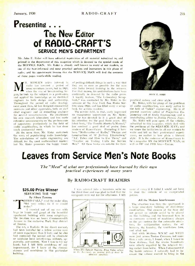
SERVICE MEN'S DEPARTMENT Mr. John F. Rider will have editorial supervision of all material submitted to, and
printed in the department of this magazine which is devoted to the special needs of the SERVICE MAN. Mr. Rider is already well known to many of our readers, as
one of the best -informed and most practical authors and instructors in this phase of
radio; and his appointment insures that the SERVICE MAN will find the contents
of these pages worthwhile reading.
M It. radio
RIDER'S covered
interest in tnd io Intl Soy ci1i a period of ,som SC%entet11 ) vac,; hut in 1421,
wl1111 the cat ut htnadeasling be- gan, he took up the subject as a profession, and applied his knowledge us an cleetri(aI engineer to both design :uul authorship. Throughout the period of radio develop- ment .since then, he has designed commercial receivers and other apparatus, both as stmt chief engineer and as consulting engineer for several manufacturers. IIe established his own research laboratory and has made extensive umasoreinents on the performance of apparatus; particularly in the field of audio amplification, in which he has done much e rein) work.
At the same time, Mr. Rider undertook the work of popularizing radio knowledge. The calculations of radio) engineering are difficult for the most mathematical reader; but \lr. hider possesses the happy knack
of putting difficult things in such a way that they are as easy as pussihlt' for the maul who lacks formal training in the sietwes. l'or that reason, his coat rihul inn. luny 111411
tootinuatlly in demand M the radio press. .\ weekly feature, "The lahurntary Scrap- book was eonduetrd by 1Ir. Itider in the minions Of the .Yew )ark Sun Radio See- Him since 1422; and has filled many a scrap- book for serious readers.
The service held. in fact, early impressed its tremendous importance on \Ir. ltidcr, and lie has devoted to it a great dead of his attention for the past three years. Ills latest hook, "'l'hr Trouble Shooter's Manual," has rcetived a good deal of praise front readers of if..utu- ('R.wrr. Preceding it have lawn "llaathriuintics of Itadit,,' "Design and Construction of 'II' Jtattiry Eliminators,' ". 't.('. 'Tithes and How to lase Them," and "Treatise. un 'Testing Units for Service Men." All these hooks are notable for their
295
JOHN F. RIMER
practical Rature and clear style. \Ir. Rider, with his grasp of the problems
of audio ainplilieatinn, was early active in the field of "talkie" engineering. lie is at present :15501i:itt. editor of I'eoitetiuu. En- gineering and of Radio l;'unintr ring ; and a
contributing editor tu Moi las i 'i, tu re Mr. Hider will pass upon all the articles,
submitted to this magazine. which deal with the problems of the SERVICE MAN; and we renew the invitation to all our readers to write and tell us their professional experi- ences, no matter in how plain a literary style. It is the tndcan'ur of it snot- l'aster to be a magazine BY the SERVICE \I.1N, as well as OF and 1.1)It hint.- l:ola'us.
Leaves from Service Men's Note Books The "3leat" of what our professionals have learned by their own
practical experiences of many years
$25.00 Prize Winner SERVICING TILE "400"
By Albert Turenne 't IIIItD CALI.,' read the order slip;
"Set very noisy; fix it or cannel order."
I crawled out of my car with bags in hands and gazed at the beautiful apautnicitt building with some utisgiV in_s. The location was on lower Commonwealth .lycuuc in the exclusive Back Bay district of Roston.
The set, a Radials 18 for direct current, had been installed by a fellow service soon of more experience than I had; and he also had answered the small] call to eliminate or minimize local interference without, ap- parently, any success. Now I was to try my hand; but I felt little confidence of any improvement, for I knew of the circum- stances and conditions in this particular building.
By RADIO -CRAFT READERS
I was ushered into n luxurious suite oui
the third floor and wits glad to find that the occupants were out for the afternoon. I ftlt
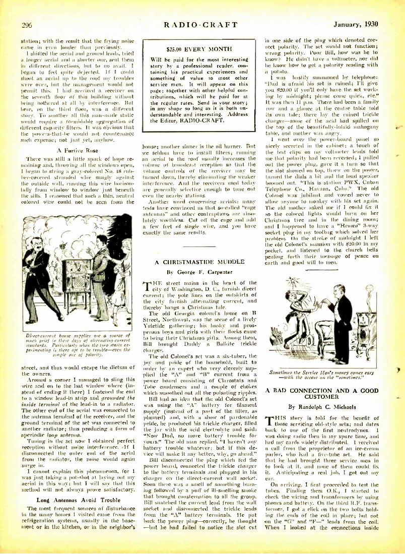
When Als .Satanic lfairsty, King Noise, reigns iu ti :r lut.,i,nrnt, au, oa txidc pirlap matt be
obtained somehow.
Inure :il as.' if I failed I would not have tu face tlu ridicule of an exasperated pal run.
All the Modern Interferences
'l'ht situation was this: the apartment is
a large Hint -story building of steel-frame construction. 'Fla.'. owners at the tittle did not permit an 011 kill(' :uri :al lo he placed on this iniltling, and the basement here is nn cnnruums network of machinery :always un the go)- uudors for the autnm:dic eleva- tors. the refrigeration system, the nil burners, the laundry. the ventilation fans, and what not.
. \nd while Stations \CN. \t' and \1'EEI were just across 'Ruston Common. not more than a mile nwa, 1 found. when I tuned in those stations, Ihat the studio broadcasts were utterly engulfed by Ilan infernal fry- ing racket frai below. \\-hen I disconnected the inside antenna I naturally had to in- crease the %o mac control tu I :riif_ in the
2% RADIO -CRAFT
station; with the result that the frying noise canoe in even louder than previously.
1 shifted the aerial and ground leads, tried a longer aerial and a shorter one, sent them in different direction., but to no avail. I began to feel quite dejected. If I could shoot an aerial up to the roof uty troubles were over, but the management would not permit this. I had serviced a receiver on the seventh floor of this building without being bothered at all by interference But here, on the third floor, was a different story. To smother all this nun -made static would require a frittidable aggregation of different capacity filters. It was obvious that the powers- that -be would not countenance such expense; not just yet, anyhow.
A Furtive Ruse
There was still a little spark of hope re- maining and, throwing all the windows open, I began to string a gray -colored No. 18 rub- ber-covered stranded wire snugly against the outside wall, running this wire horizon- tally from window to window just beneath the sills. I reasoned that such a thin, neutral colored wire could not be seen from the
Direct- current house supplies are a source of much grief in there days of alternating -parent standards. Particularly when the tyro starts ex- perimenting is there apt to be trouble -even the
simple one of polarity.
street, and thus would escape the dictum of the owners.
Around a corner I managed to sling this wire and on to the last window where (in- stead of ending it there) I fastened the end to a window lead -in strip and grounded the inside terminal of the lead -in to a radiator. The other end of the aerial was connected to the antenna terminal of the receiver, and the ground terminal of the set was connected to another radiator; thus producing a form of aperiodic loop antenna.
Tuning in the set now I obtained perfect reception without noise interference. .If I disconnected the outer end of the aerial front the radiator, the noise would again surge in.
I cannot explain this phenomenon, for I was just taking a pot -shot at laying out my aerial in this way; but I will say that this method will not always prove satisfactory.
Long Antennas Avoid Trouble The most frequent sources of disturbance
in the many homes I visited carte from the refrigeration systems, usually in the base- ment or in the kitchen, or in the neighbor's
$25.00 EVERY MONTH
Will be paid for the most interesting story by a professional reader, con- taining his practical experiences and something of seine to most other service men. It will appear on this page; together with other helpful con- tributions, which will be paid for at the regular rates. Send in your story; in any shape so long as it is both un- derstandable and interesting. Address the Editor, RADIO -CRAFT.
house; another sinner is the oil burner. But we seldom have to install filters; running an aerial to the roof usually increases the volume of broadcast reception so that the vol controls of the receiver may be
turned down, thereby el' ating the weaker interference. And the receivers used today are generally selective enough to tune out even the nearby stations.
Another word concerning aerials: many tests have convinced us that so- called "cage antennas" and other contraptions are abso- lutely worthless. Cut off the cage and add a few feet of single wire, and you have exactly the saute results.
A CHRISTMASTIDE MUDDLE
By George F. Carpenter
TI 1 street mains in the heart of the city of Washington, D. C., furnish direct
torrent; the pole lines on the outskirts of the city furnish alternating current, and thereby hangs a Christmas tale.
The old Georgia colonel's home on B Street, Northwest, was the scene of a lively Yuletide gathering; his husky and pros- perous boys and girls with their flocks carte to bring their Christmas gifts. Among them, Bill brought Daddy a Ba'kite trickle charger.
The old Colonel's set was a six- tuber, the joy and pride of the household, built to order by an expert who very cleverly sup- plied the "A" and "13" current frotti a power board consisting of Clarostats and ' l'otie condensers and a couple of chokes which smoothed out all the pulsating ripples.
Bill had an idea that the old Colonel's set was using the "A" battery for filament supply (instead of a part of the filter, as
planned) and, with a show of pardonable pride, he produced his trickle charger, filled the jar with the acid electrolyte and said: "Now Dad, no more battery trouble for yours." The old man replied, "I haven't any battery trouble whatever; but if this de- vice will stake it any better, why, go ahead."
Bill disconnected the plug which fed the power board, connected the trickle charger to the battery terminals and plugged in his charger on the direct- current wall socket. Soon there was a smell of something burn- ing followed by a puff of ill -smelling smoke that brought consternation to all the group. Bill snatched the current lead front the wall socket and disconnected the trickle leads from the "A" battery terminals. He put back the power plug -correctly, he thought -but he had failed to notice the slot cut
January, 1930
in one side of the plug which denoted cor- rect polarity. flue set would not function; wrong polarity. Poor Bill, how was he to know: He didn't have a voltmeter, nor did he know how to get a polarity reading with a potato.
I was hastily sununoned by telephone: "I)ad is afraid his set is ruined; I'll give you $20.00 if you'll only have the set work- ing by midnight; please come quick, etc." It was then 11 p.m. There liad been a family row and a glance at the centre table told its own tale; there lay the r d trickle charger -some of the acid had spilled on the top of the beautifully -inlaid mahogany table, and another was angry.
I went over the power -board panel so
nicely secreted hi the cabinet; a touch of the test clips on my voltmeter leads told me that polarity had been reversed; 1 pulled out the power plug, gave it a turn so that the slot showed on top, threw on the power, turned the dials a bit and the loud speaker boomed out. "This is station PWX, Cuban Telephone Co., I-I:nana, Cuba." The old Colonel was jubilant and vowed never to allow anyone to monkey with his set again. 'l'he old mother asked me if I could fix it so the colored lights would burn on her Christmas tree and in the dining room; and I happened to have a "Hentco" 3 -way socket plug in my toolbag which solved her problem. On the stroke of midnight I left the old Colonel's mansion with $20.00 in my pocket, and listened to the church bells pealing forth their message of peace on earth and good will to men.
Sometimes the Service Man's money comes cosy -with the accent on the "sometimes."
A BAD CONNECTION AND A GOOD CUSTOMER
By Randolph C. Michaels
THIS story is told for the benefit of those servicing old -style sets; and elates
back to one of the first neutrodynes. I was doing radio then in my spare time, and had my cards widely distributed. I received a call front the proprietor of an ice- creant parlor, who had a five -tube set. He said that he had brought three service men in to look at it, and none of them could fix it. Anticipating a real job, I got out my ca r.
On arriving, I first proceeded to test the tubes. Finding then O.F., I started to check the wiring and transformers by using phones and battery. On the third R.F. trans- former, I got a click on the two bolts hold- ing the ends of the coil in place; but not on the "G" and "F -" leads from the coil. When I looked at the connections inside
y
9 Radio Service Data Sheet
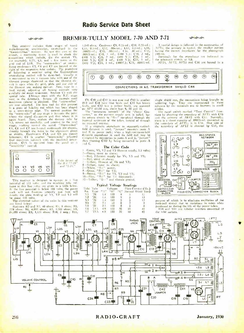
BREMER -TULLY MODEL 7 -70 AND 7.71
This receiver includes three stages of tuned radio- frequency amplification, neutralized in the "Countcrphasc" manner. To test this part of the circuit, a continuity tester k used to check the
lull ectimns which include, (in the circuit VI, fur example), L2N, l'5, :tint a few turns at the grid cud of LIS. The "micro- mike," or neutra- lizing condensers C5, Ct, and C7 are located at the right of the respective tube sockets. The procedure of balancing a receiver using the Countcrphase neutralizing method will be described. Usually it is convenient to use a vacuum tube with one of the 6lameut prongs shortened so that the filament cir- cuit is open when the grit!, plate and one side of the filament are making contact. Now, tune in a
loud signal, adjusting all hoeing controls very carefully for exact resonance. Replace V3 witlt the
special tube. (Always start with the R.F. stage
next to the detector). Rctune all controls until maximum volume is obtained. The "micro- mikes" are now adjusted. The best tool for this purpose is a piece of bakclite rod which has been shaped
to a screw -driver edge. The correct position for the "micro -mike" of any stage is between the point where the signal disappears and that where it is again heard. Now, replace the dummy tube by \ 3, retinue set carefully, au"I proceed to the next stage; working toward the aerial. "Micro- mikes" C5, C6 and C7 are i. catch underneath the chassis, directly beneath the holes in the aluminum plates or shields. Condensers CIA and C8 arc circuit balancers; C8 is another "micro-mike" adjusted (fur maximum volume) with the insulated screw- driver. CIA k opt rated from the panel as a "sensitivity" control.
VS o ö
V4 V3 V2 V6 Vi 0 0 0 0 0
Tube layout of the R.I. "7-70"
aud ' . 71."
This receiver is designed to operate at a line potential of 115 volts, and the resulting tube vin- tages at this line value are given in a table below. li the line potential is below 100 volts, the power pack will not function properly and hum will result; the plate reading of VI, V2 and V3 will be about 135 volts.
The electrical values of the units in this receiver art) listed below:
Resistors R2 and R3, 40 ohms; R4, 8 ohms; R5, 770 ohms; RG, 4,000 ohms; R7. 1.700 ohms; R8, 34,100 ohms; R9, 1,125 ohms; RIO. 3 meg.; R11,
C6
L2S V2
1.540 ohms. Condenser C9, 0.25-mf.; ('10, 0.25-mf.; C11, 0.5 tuf.; C12, .00o-mL; C13, 0S-mf.; C14, .00023-mf.; C15, .003-nnf.; ('lo. .01-mf.; C17, .00025-mf.; C18, 1 mf., (400 \'.); C19, 2 inf., (400 V.); 1220, 2 mf., (400 V.); C21, 1 mf., (160 V.); C22 1 mf., (400 V.); C23, 1 tnf., (400 V.); C24, 1 mf., (400\'.); C25, .00025-inf.
.\ special design is followed in the construction of .\PT1; the primary is tapped, the smaller portion having the correct impedance for the phonograph pickup.
Terminals for the reproducer are indieut d ;nt
the schematic circuit as LS. AFfl, AFT2, AFT3 and C16 are housed in a
O ® ® O ® © ® ® ,0 ,z O O
CONNECTIONS IN A.F. TRANSFORMER SHIELD CAN
C9, C10 and C11 in one case and C13 in another ((9 and CIO have blue leads :uul C11 has brown (cads, and C13 has a yellow lead), are mounted on AFT shield can, above lugs 9, 10 and I1.
The "resistance network" of the "Power Con- verter," as the current supply unit is called, has its return circuit to "11 -" completed through the internal resistance of the tubes, instead of through an external resistor.
If a magnetic reproducer or separately-excite-4- (mill dynamic is used, "jumper" connects posts A and Ti in )rower pack; when a high -resistance -field dynamic reproducer is used its field coil may be energized by connection to posts .1 and B, "jumper" then shorting CH2 by being connected to posts A mud C.
The Color Code I - Green, VI, \3 and V3 filament supply, 1.5 volts; 2- Green, same as ahueve; ' -Red, Filament supply for \'4, V5 and V9; I- Red, same as allure;
\'elbow, filament of V6 and V7; 6- Yellow, saute as above;
s7-White, "B +" power;
-Green, "I1 +" for V5; 9- Brown, "B +" for \'I, V2 and V3; 10-Blue, "B +" for V4 (detector); 11- Yellow, "It -" and chassis ground.
Typical Voltage Readings 'Cube Tube Voltages Plate Current (Ma.) No. 1'ype ". \" "B" "C" Normal (Grid Test) VI '26 1.4 150 9 5 12 V2 '26 1.4 150 9 5 12 V3 '26 1.4 150 9 5 12 V4 2.1 60 O 2 2 V5 '27 2.1 150 8 5 8
'71.\ 4.9 150 30 18 41 V7 '71.\ 4.9 150 30 18 41
L3P Cl
L35 V.
L4P
1 t C3
L3N LF4Nr
-_ Brb M 10
AINIMMEM=Bigliff.
298
VOLUME CONTROL
Ri
C- B
L4S
o
single shield can, the connections being brought to soldering lugs. They are represented in these columns by the numerals one to fourteen in small circles.
The panel switch marked "Tone Control" func- tions by shinning the secondary of AFT' with C15 anal the primary of .\lí1'2 with 010. Normally, there is a shunt capacity of .00025 -mf. connected to the secondary of Al -'TI; it is (214. One side of the secuudary of AFT2 is shunted by (217, the
R3
i R4 r
BIAS)- r- TAP RESISTOR rJUMPER
R2
PQL7 o 5
L8
db 1.6
LAO
'---w(.) CPO L5
d(L7 o
RESISTANCE NETWORK
17679 fRT
4RS
CONDENSER
® CH
SWITCH LEAD CONNECTOR
R FIELD COIL1CONNECTOR
A ®IC
BLOCK
p trpose of which is to eliminate oscillation of the push -pull circuit due to variations in tubes when p trchaseel or during the life of the power tubes.
RIO and R11 are tubular resistors connected at the tole sockets.
TONE CONTROL
C$5
C25 V4 á
'C 6
R11
N9 5
iM
..5
L.5
Be
t10 1.r,C.
N P2 Sv LIO
N
C9
1.5 V L9
GN 2 3
C10 BN
Tw it
I
C11
9
R8
C24 T
8 A
C21
C231-
RADIO- CRAFT
CH2 JUMPER
TC20 PT
January, 1930
January, 1930
the coil, I found the nut had loosened slightly; and the lug was perfectly centered around the bolt, without touching either nut or bolt. I tightened the nut, and the set worked like a charms.
The owner did not ask me what my charge was; but handed me five dollars for my fifteen minutes' work and called it square. This proves that connections are not always as good as they look, and that real service men are in demand.
(We think that real service customers like the gentlemen described in the story are even more in demand. Editor.)
"NAILING DOWN" THE HUM By J. E. Bourke
DURING lonely watches at sea, with a pair of phones on my ears for six to
eight hours at a stretch, your magazine has helped to pass away the lonely hours. I am now getting off the ship to look for a serv- ice job ashore again; and I honestly believe that your magazine gets home to the service man better than ant- of them.
Like most of the old- timers, I have had to perform a lot of "wrinkles" to keep a radio set working; but like most of the others, thought nothing of them at the tine. The only objective was "It must work." How-
OPEN PRIMARY
Fig. I An emergency repair pith which every radio
mat should be familiar.
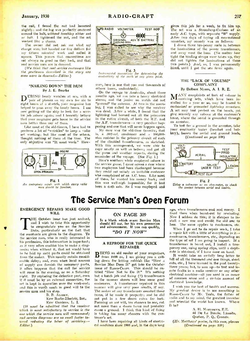
RADIO -CRAFT 297
VOLTMETER TEST ROO
6 11111111 ORIGINAL 45V.'ß BATTERY.
ROUND ROD.
Fig. 3 Instrumental connections for determining the conductivity of the earth at any given point.
ever, here is one that YOU and thousands of others know, undoubtedly.
On the voyage to Australia, about three months ago, we ran into a heavy electrical storm; and the junior on watch did not "ground" the antenna. At two in the morn- ing, I was called to see why the receiver was dead. After a while, I found that the lightning had burned out all the primaries in the entire circuit, of both the R.F. and the A.F. transformers -a very peculiar hap- pening and one that will never happen again.
My cure was the old -time favorite; that is, a .002 -mf. condenser and a 100,000 - ohm resistor in the primary circuit of each of the disabled transformers, as sketched. With this arrangement, we were able to copy nearly as well as before; and got all the press and weather reports, during the remainder of the voyage. (See Fig. 1.)
Here's another: while employed ashore in the service game, I came across a case where two employees had been discharged because they could not satisfy an irritable customer who complained of an A.C. hum. Like most of them, he wanted his money back; and this was well -nigh impossible, for it had been a cash sale. So I was employed and
given this job for a week, to fix him up The set was a Stromberg- Carlson of an early A.C. type, with separate "B" supply After two days of trying all conventional remedies, my remedy was as follows:
I drove three ten-penny nails in between the laminations of the power transformer, and away went the hum. (No matter how tight the binding straps were taken up, the) did not tighten the laminations at these two points.) And, so, I was permanently hired, until I got the sea fever again.
THE "LACK OF VOLUME" COMPLAINT
By Delbert Myers, A. I. R. E.
MANY complaints of lack of volume in
receiving sets, which have been in- stalled for a year or so, may be traced to carbonized or grounded lightning arrestors.
A set may test perfect on the bench, yet give scarcely any volume at the customer's home, where the aerial is grounded through an arrestor.
To test for a ground in the arrestor, take your continuity tester (headset and bat- tery), loosen the aerial and ground leads,
(Continued Ou page 3:38)
VOLT- METER TEST
--PROD INSULATOR
SPLICE UNDER TEST
hldllt=
LEADIN
Fig. 2 Using a voltmeter as an ohm -meter, to check
the contact between aerial and lcaddn.
The Service Man's Open Forum EMERGENCY REPAIRS MAKE GOOD
WILL
THE October issue has just arrived, and I wish to take this opportunity to congratulate you on the Service Data, particularly on the fact that
the constants are given to the diagram. To the service man, who is really interested in his profession, this information is important; as it very often enables him to make a diag- nosis; when without it, that set would have to he laid up until parts could be obtained from the maker. This usually entails consid- erable delay; and, even when local sources of supply can furnish the necessary parts, it often happens that the call for service will come in the evening, or on a Saturday night. By replacing the defective part, even if it must be by an external connection, the set is kept in operation over the week -end; and this is worth much in good will to the service man and his shop.
B. B. ALCORN, Kew Radio- Electric, Inc., Kew Gardens, L. I.
(It must be admitted that the receiver which is most satisfactory to service is the one which the service man will recommend; and service diagrams are no small factor to- ward reducing the labor of servicing. - r,rttar N
ON PAGE 309 Is a blank which every Service Man should fill out, for his own protection and advancement. If you can qualify,
"DO IT NOW"
A REPROOF FOR THE QUICK REPAIRER
TIEING an old reader of your magazines, from 1908 on, I am giving you a call-
ing down for letting rubbish like "How a Service Man Does It" get into the October issue of RADio- Cam-r. This should be en- titled "How Not to Do It" It's nothing but a botch job and fixing ( ?) transformers in the manner shown will lose some good customers. A transformer repaired in this manner will give very poor results, if any. The maker of any transformer counted those turns, if he made it properly; and he dill not put in a few dozen extra for luck. Forming an arc will, ten chances to one, cut out more than a dozen turns and probably cause a ground. I think this kind of fixing is taking too many chances with the cus- tomer's set.
I have been repairing all kinds of electri- cal mnrhinec cinrr loaf nnd_ in tun rinrc Innn
ago, when transformers cost real money. I fixed them when burnt -out by rewinding. Now I seldom do this; it is cheaper to in- stall a new one and credit the old one to loss. 'l'he same applies to condensers, etc.
When I go out to do repair work, I take a repair kit with a little of everything in it- condensers, transformers, etc., depending on the type of set I am going to inspect. If a transformer is burnt out, I install a tem- porary one, using spring clips, until a dupli- cate is obtained, if I have none on hand.
It would take an awfully long letter to tell of all the thousand and one things, short cuts, etc., I have learned in the past twenty - three years; but, to sum up -to test and lo- cate faults in a radio receiver or any other electrical machine -all you need is an ounce of common sense and a certain amount of electrical knowledge.
I wish you My greatest RADIO -CRAFT radio and to and scientist IS he?
the best of health and success. desire is to see something in by Mr. Tesla, the father of
my mind, the greatest inventor the world has known. Where
A. H. MATTIIEws, E.E. 46 De La Ronde, Limoilu, Quebec, P. Q., Canada.
(Mr. Matthews' praise, in this case, pleases trni nnr,1 ..n ,,..,.e nsot
epsepotQ(
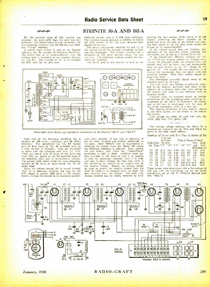
On the terminal strip of this receiver are mounted: the power-cable lugs; the grid leak and condenser; the detector -plate by -pass condenser; the two center -tap resistors; and the 600 -ohm and 2500 - ohm "C- bias" resistors.
A special input circuit is used on the Steinite receivers, for the purpose of obtaining sensitivity. The circuit acts as an autotransformer when the antenna lead is connected at the junction between 1 -1 and CI. The purpose of RI is to complete the D.C. path for the grid bias.
Radio Service Data Sheet lo
STEINITE 50 -A AND 102 -A clockwise position cuts in 75,000 ohms additional. The resulting biasing potential is sufficient to reduce the plate current to nil; and even powerful local signals are cut out.
The output transformer matching V6 and V7 to the moving coil of the dynamic reproducer is built into the reproducer. The primary winding has a
resistance of 285 ohms between center tap and each end. The secondary winding matches the low - resist:uce voice -coil.
The power pack of this receiver is built un the
(ROAN
AIRC. ( IRLOS
FRON
nn0W
a I
nnW
Cw -n. L= S: - e ssr ' ss ó é
OOCIOO ®OO 1 Vd VI
12 TI
0 VS
FIELD CAL\
ALI DN INO
CONDENSERS Dol i
Y 755414 44
13
VIM coo
Pn
FC
V4n
V6-V7 tt
L'oser -pack parts layout and reproducer connections of the Stcfnfte "SO -A" and "102 -A.'
Each unit of the four -gang condenser has a capacity of 380 mmf., maximum, and 30 mml., minimum. The secondaries 1.3, L6, L9 consist each of 87y, turns of No. 30 enameled wire on a tube 1;6 -inch in diameter. They are connected in series with the balancing coils (L4, 1.7, 1.10) which are wound with 32 turns of the same size wire; they are placed at the low -potential ends of the secondary coils. and in non- inductive relation. The primary coil, placed inside the main secondary, consists of 24 turns of space -wound No. 38 ad- vance wire.
\\'hen the volume control R4 is turned entirely "on" in a clockwise direction the bias on the R.F. stages is normal (600 ohms in the cathode leads); turning this control to its maximum counter-
GND 5. L. 25 100 VI 1.2 13
3
unit plan; whereby, if one unit is defective, it can be easily removed and another substituted in its place. Some difficulty may be experienced in removing the chassis from the Model 102 unless the following procedure is followed. First, remove the two screws with which the "Radio - Phono" escutcheon is held in place. Sufficient slack has been provided in the leads so that it is possible to raise the escutcheon assembly, turn it on edge and pass it down through the hole into which it fits, permitting its removal as an integral part of the receiver chassis. Second, no attempt should be made to remove the receiver chassis from the shelf to which it is attached until the shelf has !Well removed from the cabinet. The shelf with chassis attached can be readily removed by with-
V2 LS L6
a> -
YS LB L9 331331E6!-* EG.
C1
drawing the four screws which secure it to the cabinet, permitting the entire assembly to loe
pulled out from the hack of the cabinet and mak- ing easy access to the six bolts which secure the chassis to its supporting- shelf.
If the volume control does not function, con- sideration of the schematic circuit indicates that the trouble may be due to a shorted C2 or C3.
If the transformer's filament winding,: for V4- V5 VS -V9 are making contact or flashing over, resistor 122 (situated under the terminal strip and colored red) will be burnt out and consequently show an open circuit, or no "C" voltage on the grid of \-5. The remedy for this condition is to remove the transformer front the power pack and substitute another. Only early models should re- quire this repair.
The phonograph turntable should rotate at the standard speed of 78 r.p.m.
Any hum which may develop is ordinarily trace- able to the detector; particular care taken in the selection of a detector tube when first setting up the receiver will result in hest operation over an extended period.
Variation from the standard circuit to include connections for the phonograph -radio switching ar- rangement on the 102 -A is illustrated; the schem- atic is laid out to correspond with the view of the switch escutcheon, which is a rear one.
The aligning condensers of this receiver, shown in the parts layout, are not shown in the schem- atic circuit.
Line voltage tap colors of pack are: red, 90; white, 100; blue, 110; green, 120.
The average voltage readings (as shown by a standard set analyzer) for the 50 -A and 102 -A are given in the table which follows:
Readings of Tester with Test Plug in Socket of Set Tube out of Tester Tube in Tester (Volts)
Tube Tube (Volts) Nor- Grid No. Type "A" "B" "A" "B" "C" mat Test
Milliamperes VI '27 2.75 134 2.45 125 6.5 4.25 13.0 V2 '27 2.75 134 2.45 125 8.7 5.0 14.0 V3 '27 2.75 134 2.45 125 -8.7 4.8 13.6 \'4 '27 2.65 92 2.40 32 . 2.5 VS '27 2.65 144 2.40 118 8.2 3.6 9.0 V6 '50 7.7 355 7.40 310 51.0 36.0 98.0 V7 '50 7.7 355 7.40 310 51.0 36.0 98.0
These values were determined with a line -voltage of 110 and with the line -voltage tap on the power transformer set at 110 V. (Volume Control posi- tion "Max. ")
V4 T1 VS 72 V6
IRR 1
L4
C2
.5 MF. 1 600
OHMS
t11041 EIDIO
44 um TS000 C4
OHMS LYE
C6
PICK
UP
IEIDS
ty
January, 1930
DIT
Bi TO PICK -UP
C3 .5 MF.
END OF
CHASSIS
Eritm;; 111I11111111I1M11111
MMM449944 4444
MÏIMMMMM bldtb3d4d5tO
6 TdsdSbmdtt
TO V6 A VT
ON TI Dial LAMP
01
O Ira 1[11
RADIO- CRAFT
TERMINAL STRIP IN CHASSIS
o
299
31K1 RADIO -CRAFT January, 1930
Servicing the Freshman "Model N"
In this article, the second of a series, Mr. Weiler not only goes into detail about the work of checking up on the receiver named, but gives many hints of general value
THE second receiver to he described is the Freshinan "N." This model has an untuned antenna stage; being untuned, this tube amplifies every-
thing and it is claimed, by some technicians, that its use results in greater broadness of tuning and increased interference from static. I1ow ever this may be, the conne.tinn serves excellently to prevent the variations,
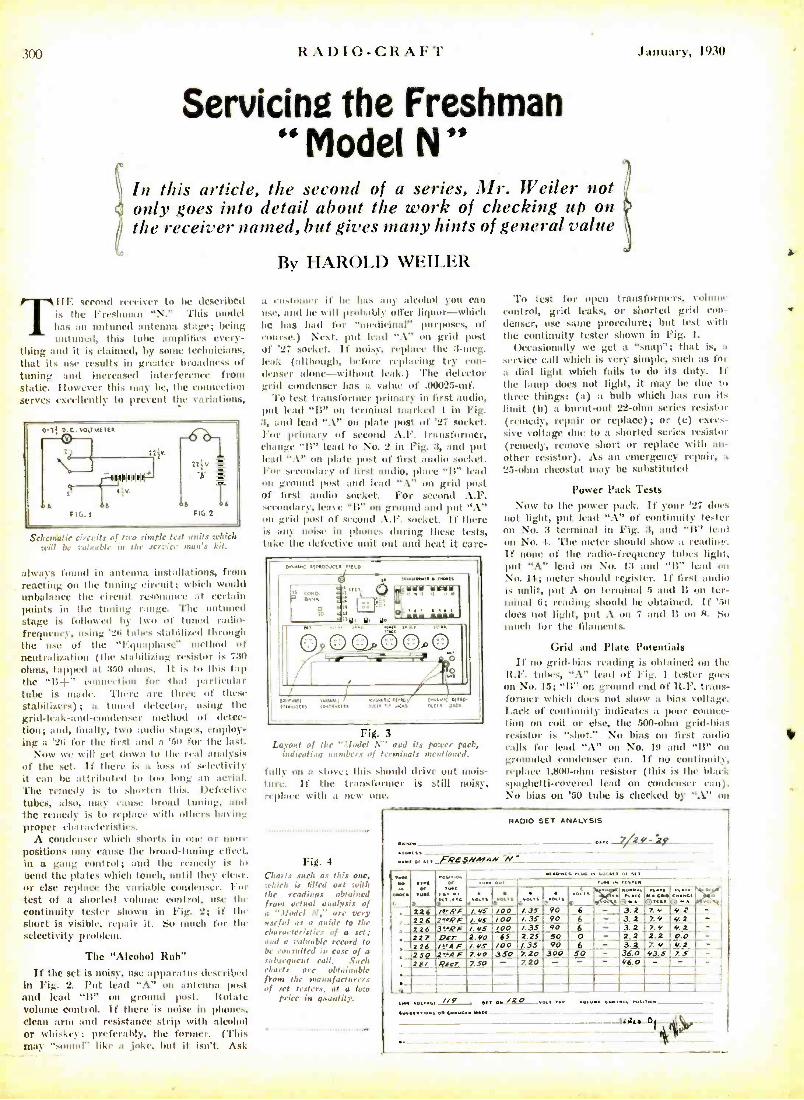
Schcnìatie circuits of tarn simple teal units which will be valuable in the service man's kit.
always found in antenna installations, from reacting on the tuning circuit; which would unbalance the circuit resonance at certain points in the tuning range. The uni t
stage is follow mal by two of tuned radio- frequency, using '26 tubes stabilized through the use of the "I:Anaphase" method of neutralization (the stnhilizing resistor is 7313
ohms, tapped at 350 gluas. It is to this tap the "11- -" (,,iìiie,'I i. mi for That part kola r tube is made. There are three of these stabilizers); a tuned detector, using the grid- leak- and -condenser inethod of detec- tion; and, finally, two audio stages, employ- ing a '21i for the first and a '51i for the last.
Now we will get dozen tu the real :analysis of the set. If there is a. loss of selectivity it can be attributed to too long :un aerial. The remedy k to shorten this. Defective tubes, also, may cause broad tuning. :und
the remedy ís to rcplaee with others toning proper ch :nacterivties.
A Condenser which shorts in one or mure positions may camuse the broad- tuning effect, in a gang control; and the remedy is to bend the plates which tomb, until they clea r. r else replace the variable condenser. For test of a shorted volume control, use Ille continuity tester shown in Fig. 2; if the short is visible, repair it. 5o much for the selectivity proleu,.
The "Alcohol Ruh"
If the set is noisy, use apparatus described in Fig. 2. Put lead "A" un antenna post and lead "B" on gro 1 post. Rotate volume control. If there 'is noise in phones, clean arm and resistance strip with alcohol or whiskey; preferably, the former. (This may "snood" like a joke, but it isn't. Ask
By HAROLD WEILER
a customer it' he has :env alcohol you can use, :nul he twill probably greyer liquor -which he has had L'or "medicinal" purposes, of course.) Next, put lead ".\" on grid post of '27 socket. If noisy, replace the :3 -meg. leak (although, before replacing try con- denser :done- without Irak.) The detector grid condenser has a value of .00IP2 -mf.
To test transformer primary in lirst audio, put lead "B" on terminal marked 1 in Fig. 3, and lead "A" on plate post of '27 socket. For primary of second A.F. transformer, change "It" lead to No. 2 in Fig. 3, and put lead ". \" on plate post of first audio socket. For secondary of first audio, place "II" lead un grotmd post and lead ".\" on grid post of first audio socket. For second A.F. secondary, It':,se "B" on ground and put ".\" on grill pmt of sorond A.F. socket. if there is any noise in phones during these tests, take the defective unit out and heat it care-
o.44.04 al,ooucc, mu,
.. 5( Is ä K'
o
'0' IF W o,a.
09ÓÇQ OOO HO
I .."I n u,nns
.MI / m+ ,.nu
,aG I' c ano: 07.01C .. .aa ,".
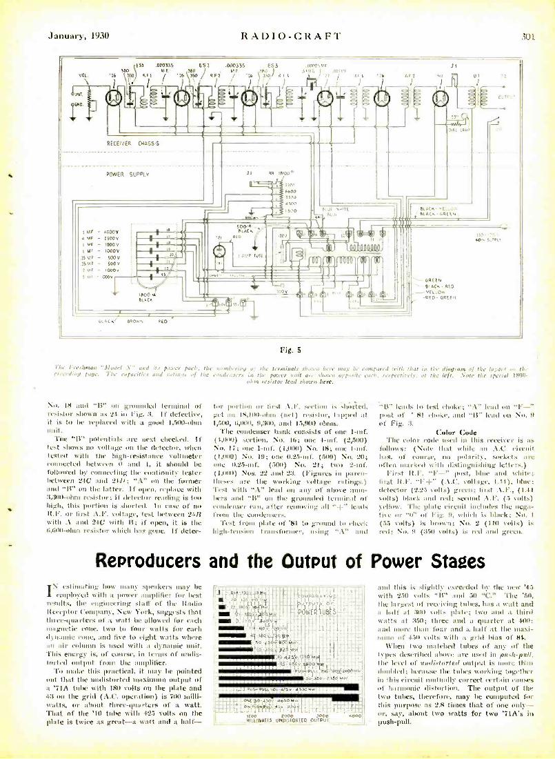
Fig. 3 Layout of the "Model V" and its power pack,
indicatiog nombn's of terminals mentioned.
lull' on a slim.; this should drive out mois- ture. If the transformer is still noisy, r1plaec with a new une.
Fig. 4 Charts such at this arc, which is filled out with the readings obtained from actual analysis of a "Model A"," are very useful as a guide to the characteristics of a set; mud a valuable record to br consulted in case of a subsequent call. Such charts are obtainable fiom the manufacturers of stet osiers, at a Iota
price IN quantity.
'1'o test for open transformers, vohuue control, grid leaks, or shorted grid con- denser, use same procedure; but test with the continuity tester shown in Fig. 1.
Occasionally we get a "snap "; that is, a
service call which is very simple, such as for a dial light which fails to do its duty. If the lamp does not light, it may be due to three things: (a) a bulb which has run its limit (b) a burnt -out 22 -ohm series resistor (remedy, repair or replace); or (e) exces- sive voltage due to a shorted series resistor (remedy, remove short or replace with an- other resistor). As an emergency repair, a
25 -ohm rheostat may be substituted
Power Pack Tests Now to the power pack. If your '27 dams
not light, put lead "A" of continuity tester on No. 3 terminal in Fig. 3, and "li" lead on No. 1. The meter should show a rending. If none of the radio -frequency tubes light, put "A." lead on No. 13 and "11" lead ern
Nu. 14; meter should register. If first audio is unlit, put A On terminal 5 and B on ter- minal O; reading should be obtained. If '.So
does not light, put A on 7 and 11 on R. So much for the filaments.
Grid and Plate Potentials If 00 grid -bias rending is obtained on the
13.F. tubes, A" Irad of Fig. 1 tester goes on No. 1.5; "B" nn ground end of It.F. trans- former which does not show a bias voltage. Lack of continuity indicates a poor connec- tion On coil or else, the 500 -ohm grid -bins resistor is 'shot." No bias on lirst audio calls for lead ".'" on NO. 19 and "Ii" on grounded a tenser cyan. If no continuity, replace 1,800 -ohm resistor (this is the black spaghetti -covered lead on condenser cam). No bias on '50 tube is checked by ".1" on
/RADIO SET ANALYSIS
... . .,. 7,2 y- i9
..na.. .a fRESNMAN_A! . . ä . .:: a,
[Ve
aw.c, .tw .. .oc-a, , a.
.w. ... toot Po
.« w.ái 90
á . 6
-
.. K t,,,' 3.2 4.2 ,
, .
/NF 2!'7F
/.4S /OO /.35 /.4S 100 /.35 90 6 3.2
3.2 7_4 7.4
4.2 4.2 2 -'F /.4S /00 /35 90 6 - ,
227 D5r. 2.40 65 2.25 00 0 - 2_2 3.2
2.2 7 4
O.O_ 4t 7.B
226 /trA.F /.4S /00 1.35 7.20
90 900 SO
- - ,
224]F 7.40 350 36.0 43.5 -e r 7.J0 - 7.20 - - - 46.0 -_ -
.
... //9 - .. e,. /20 .«. ,.. .«..a .....« ro.,..
....a.,.., e....w.. Yam
January, 1930 RAvIO-CRAFT 301
ESO .000335 ES .000335 r5,i ME / . ME B0 1 / 2t. 550 RE2 / '20
7 AA01 a 1
( )
¡YE e "' ] SOO
VOL. 16 (5fi0 RFi
en1
END
PE[EiVER CRnSSiS
P0NE7 SL!PPIv
i ME - 000V a ME - 2500v
MF - 1000V
( Mr - 1000V
15 MR - 500V 500v
1 A. f- 1000 V
7 v, - OOOV
,e
11
.DIM..,l 1.A9; ) .m.
..... . i A.
r.1 ( 07
.10!
11 1111
BLaCK'
1800 u BUCK
B',0'Na
f.
RED
eLCC..G.LE4,
GREEN B'-nCS- RED
41. EE
_. YELL .Ow -RED- GR!
Fig. 5
The Freshman "Model .\.. and its power fuck; the 111!mi'eri !f of 11.0 icrl,lineis shown /acre may be compared with that is the diagram of the the preeediva pape: 1 L capacities nid ra tir.ps of the condensers in. the power unit use shown opposite eaen. respectively. at the left. Yore the special 1501) -
ohm resistor lead shown here.
No. 18 and "13" on grounded terminal of resistor shown as 21. in Fig. 3. 1f defective, it is to be replaced with a good 1,500 -ohm unit.
The "I3" potentials are next checked. If test shows no voltage on the detector, when tested with the high -resistance voltmeter eonnected between 0 and 1, it should be followed by runnceting the continuity tester between 24e and 24p; ".\" on the furnier and "11" on the latter. if open, replace with 3,300-oboe resistor; if detector rending is toc, high, this portion is shorted. In cask' of no list'. or first A.F. collage, test between 21B with .\ and 2tU with IS; if open, it is the 0.000 -ohur resistor which has gone. If dctee-
tor portion or first . \.I'. section is .hoisted, get till 18,1111 -ohm (net) resistor, tapped at 1,51X), 8,00 41, 9,311), and 15,911) ohms.
The condenser bank consists of one 1 -tuf. (1,01)0) section, No. Ili; one 1 -nef. (2,5(10) No. 17; one 1-mt. (1,111-30) Na,. 18; one 1 -tuf. (1,111)) No. 19; one 0.25 -mf. (500) No. 20; one 0.25 -mf, (500) No. 21; two 2 -nif. (1.1100) Nos. 22 and 23. (Figures in paren- theses are the working voltage raftings.) 'l'est with "A lead on any of above num- bers and "1S" on the grounded terminal of ronalenser cant, after removing all "-f" leads troua the eondenscrs.
'l'est fion' plate of '81 to ground to check high -tension transformer. using .\" and
-"It" leads to test choke; \" lead on "t' -" Post ut' ' 81 choke, and "It" lead ou No. y
of Fig. 3.
Color Code The color rode used in this receiver is as
follmcs: ( \ate that while an : '5.C. circuit has, of course. na polarity, sockets :u'e often marked with distinguishing letters.)
First H.F. "F -" post, bloc and white: first 13.1'. "l' -{-" (.\.C. collage, h.ti), blur; detector (2.2.5 volts) green; lirst Al..., (1.41 volts) black and red; second A.F. (5 volts) yellow. The plate circuit includes the nega- tive or 'u" of Pic. M. which is black; Na,. I
(lS volts) is 1,1,1, 11: No. 2 (110 volts) is r111: NO. 9 ( :351) L.df) is red and green.
Reproducers and the Output of Power Stages stinciting how many speakers may be I ,i ila.ad with a power amplifier for last
results, the engineering staff of the Radio It eeeptor Company, New York, suggests that three- quarters of a watt be allowed for each magnetic cone. two to four watts for each d manie er', and live tu eight watts where all air column is used with a dynamic unit. This energy is, of course, in ternis of undis- torted output from the amplifier.
To make this practical, it may be pointed out that the undistorted maximum output of a '71A tube with 180 volts on the plate and 43 on the grid (A.C. operation) is 700 milli - watts, or about three -quarters of a watt. That of the '10 tube with 425 volts on the plate is twice as great -a watt and a half-
Et
4-140A200
500 3000 L L01S10R1ED OUTPUT
..o-
and this is slightly 'seceded by the new '4.5
with 250 volts "IS" and 50 "C." 'l'he '511,
the largest of receiving lutes, has a watt and :110 en Is ,:Ile; ton a half at 3 I 11 and a third
watts at :350; three and a quarter at 400; and more than t' and a half at the maxi- mum of 4511 volts with a grid bias of $4.
When two matched tubes of any of the types described above are used in ¡lash -pull, the level of audixlortet output is clore tu ii doulihd; because the tubes working together in this circuit unlfiiadly correct certain causes of harmonic distortion. The output of the two tubes, therefore, may be computed for this purpose as 2.8 times that of one only - or, say, about two watts for two 'TiA's in push -pull.
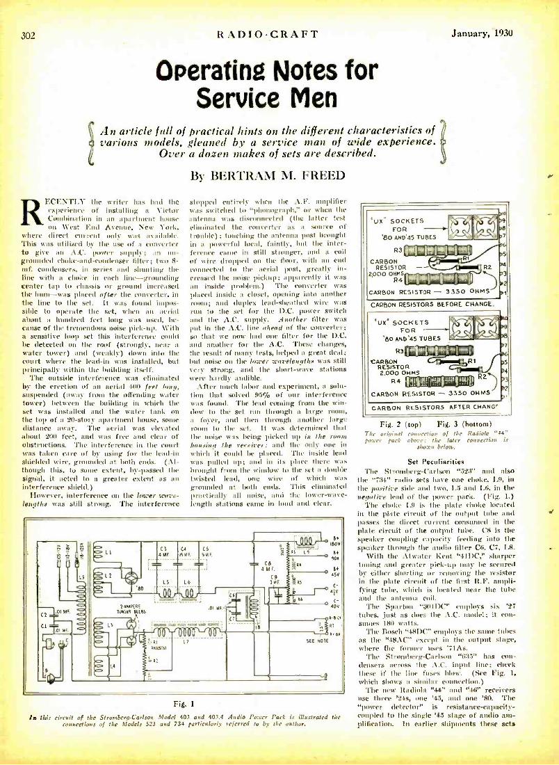
302 RADIO -CRAFT January, 1930
Operating Notes for Service Men
An article full of practical hints on the different characteristics of various models, gleaned by a service man of wide experience.
Over a dozen makes of sets are described.
RI CE.TI.Y the writer has had the experience of installing a Victor Combination in an apartment mouse on West land Avenue, New York,
where direct current only was ,n iilaMe. This was utilized by the use of a converter to give an .1.C'. power supply; an un- grounded choke -and- condenser filter; two 8- mf. condensers, in series and sl ting the line with a choke in each line -grounding center tap to chassis or ground increased the hunt -was placed after the converter, in the line to the set. It was found impos- sible to operate the set, when an aerial about a hundred feet long was used, be- cause of the tremendous noise pick -up. With a sensitive bap set this interference could be detected on the roof (strongly, near n water tower) and (weakly) down into the court where the lead -in was installed, but principally within the building itself.
The outside interference was el' ' ated by the erection of an aerial 400 feet long, suspended (away from the offending water tower) between the building in which the set was installed and the water tank on the top of a 20 -story apartment house, some distance away. The aerial was elevated about 200 feet, and was free and clear of obstructions. The interference in the court was taken care of by using for the lead -in shielded wire, grounded at both ends. (Al- though this, to some extent, by- passed the signal, it acted to a greater extent as an ' nterference shield.)
However, interference on the lower wave- lengths was still strong. The interference
By BERTRAM M. FREED
stopped entirely when the A.F. amplifier was switched b; or when the antenna was disconnected (the hatter test eliminated the converter as a source of trouble); touching the antenna post brought in a powerful local, faintly, Imt the inter- ference came in still stronger, and a coil of wire dropped on the floor, with an end connected to the aerial post, greatly in- creased the noise pickup; apparently it was an inside problem.) 'l'he converter was placed inside a closet, opening into another room; and duplex lead -sheathed wire was ruin to the set for the D.C. power switch and the A.C. supply. Another filter was put in the A.C. line ahead of the converter; so that we now had one filter for the D.C. and another for the A.C. These changes, the result of many tests, helped as great deal; but noise on the lower wavelengths was still very strong, and the short -wave stations were hardly audible.
After ouch labor and experiment, a solu- tion that solved 95% of our interference was found. 'l'he lead coming front the win- dow to the set ran through a large roost, a foyer, and then through another large
to the set. It was deter ' tl that the noise was being picked up in the room housing the receiver: and the only one in which it could be placed. The inside lead was pulled up; and in its place there was brought front the window to the set a double twisted lead, one wire of which was grounded at loth ends. This eliminated practically all noise, and the lower -wave- length stations came in loud and clear.
C6 4MF
= L2
'80 LS
/AMPERE 1UWt9 SUSS
C4 CS
bMF. SMF.
L8
Co 4MF.
C9 11.4F
.01 ME<
tA
is
A -6.0 Z il - 6,6V
SEE NOTE
o
Fig. 1
is this circuit of the StrombergCarfson Model 403 and 403.4 Audio Power Pack is illustrated the connections of the Models 523 and 734 particularly referred to by the author.
*WC SOCKETS FOR
'80 AND'45 TUBES
0
R3
CARBON RESISTOR
2000 OHMS R4 1001001411
CARBON RESISTOR 3350 OHMS
5 M 3
2 t CARBON RESISTORS BEFORE CHANGE.
UX' SOCKETS FOR
'80 AND'45 TUBES
R3
CARBON RESISTOR 2.000 OHMS R2')
CARBON RESISTOR - 3350 OHMS
R4
CARBON RESISTORS AFTER CHANG'
2 >.
Fig. 2 (top) Fig. 3 (bottom) The original connection of the Radiola '41" power tack above: the later connection is
shown bloc..
Set Peculiarities The Stromberg-Carlson "523" and also
the "734" radio sets have one choke, 1.9, in the positive side and two, 1.5 and 1.6, in the negative lead of the power pack. (Fig. 1.)
The choke 1.9 is the plate choke located in the plate circuit of the output tube and plisses the direct current consumed in the plate circuit of the output tube. C8 is the speaker coupling capacity feeding into the speaker through the audio filter C6, C7, I.B.
With the Atwater Kent "41DC," sharper turning and greater pick -up may he secured by either shorting or removing the resistor in the plate circuit of the first R.F. ampli- fying tube, which is located near the tube and the antenna coil.
The Sparton " :30IDC" employs six '27 tubes, .just as does the A.C. model; it con - sumes 180 watts.
The Bosch "48DC" employs the sane tubes as the "48ÁC" except in the output stage, where the former uses '71Ás.
The Stromberg- Carlson "635" has con- densers across the A.C. input line; check these if the line fuses blow. (See Fig. 1,
which SliOaS a similar connection.) The new Radiola "41" and "46" receivers
use three '24s, one '45, and one '80. The " power detector" is resistance- capacity- coupled to the single '45 stage of audio am- plification. In earlier shipments these sets
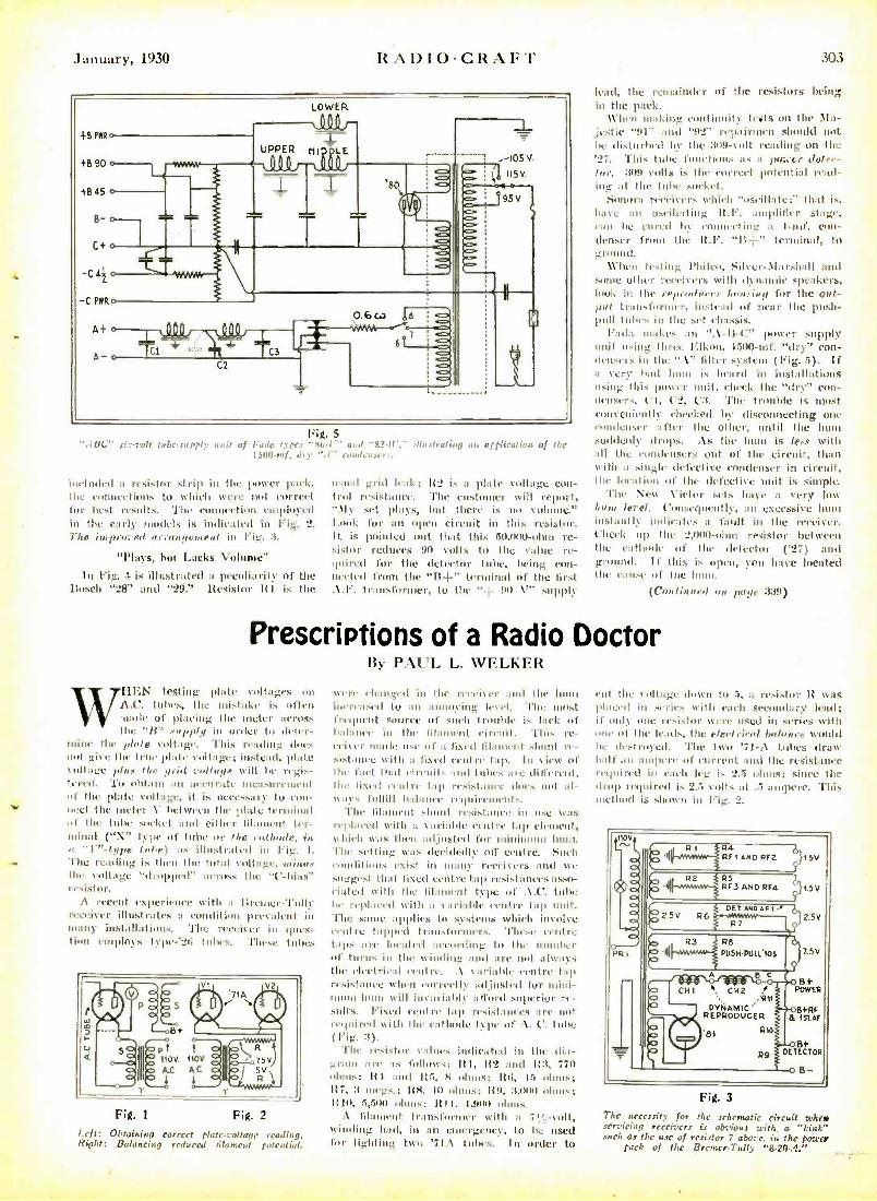
lanuary, 1930 RA1)1O-CR:1F"1'
Fig. 5 "ABC" sir-volt tubc-supply of Faja types 'sr,-1.. a,J "v,.il... ilfrsfratin aa application of the
1500-nrf. dry ".1" c,mjrnsr,..
i,wludeil a resistor strip in the power pack, the connections to which were out correct for best results. The connect' employed in the early models is indicated in Fig. 2. l'lu proved a rra o ye on to in Fig. :I.
"Plays, but Lacks Volume"
In Fig. 4 is illustrated a peculiarity of the Bosch "28" and ' "29." Resistor R1 is the
usual grid leak; lt2 is a plate voltage eon - trtil resistance. 'l'he customer will report, ' \ly set plays, but there is no volume." Look for an open circuit in this resistor. 11 is pointed out that this 50,100 -ohm re- sistor reduces 90 cults to the value re- quired for the detector tube, being eon- s, Hell from the "II +" terminal of the first .\.I'. transformer, to the " : no \ "' supply
303
lead, the remainder of the resistors being in the pack.
When making continuity fruits on the :Ma- jestic "9 1" and '92" repairmen should not he disturbed by the :tog -Volt reading on the
This. tulle ('unctions as a lance r Jrl,r- lut'. 3(19 cults is the correct potential read- ing at the tutor socket.
Sonora receivers which "(oscillate ;" that is, h;ne an (oscillating 11.1'. ;amplifier stage, eau he cured by connecting a 1 -ouf. con- denser from the It.F. "B +" terminal, to ;;round.
When toxin_ l'hilro, tiihrr- \larshall and some other receivers with dynamic speakers, look in the r.',m(1nrc,' bon..ing for the out-
instead of near the push - pull tithes in the sel chassis.
Fada snakes mn "A-It-t:" power supply snit using three Elkus, 15110 -tuf. "dry" Con - dru.sers in the ".V. lilter system (Fig. 5). If a very had hunt is heard in installations using this power unit, check the "dry" con - dettsers, ('I, ('3, l':t. The trouble is most conveniently checked by tiisconncrting one eondens,r after the other, until the hunt suddenly drops. As the huer is ln., with all the condensers out of the circuit, than with a single defective condenser in circuit, the location of the defective unit is simple.
l'hc New Victor sets have a Very low Lout L ;,d. ('utneclucntlf, nu exeessivc hunt instantly iudirat,'s a fault in the receiver, ('heck up the 2,4100 -tilun resistor between the cathode of the detector ('27) and ground. If this is open, you have located the eau.o of the hum.
(C'oulitn euf mi page 339)
Prescriptions of a Radio Doctor
WIII:N testing plate cottages on A.C. tubes, the mistah. k often made of placing the meter across
the ''B' av,p ply in order to (,ter- mine the ',fait voltage. This reading does unt give the trim plat, tillage: instead, plate %tillage plum /L.- grid r"Ilu,t, \k ill Is. regis- tered. '1'., obt:litr :Ill accurate nuanrenaut of the plate voltage, it i, nree,sa)')' to Con- nect tiro tarter \ hrlvrron the Iil;dc terminal of the tube socket :nul either filament ter- minal ( "X" type of tube tir the cathode, ill If I " -type bige) as illustrated in Fig. 1.
The reading is then the total voltage, minim the voltage "dropped" across the "C-bias" resistor.
\ recent experience with a l rcu,er -Tully remiser illustrates a cunditian prc%nlent in many inst:dlatiu is. 'l'he receiver in ques- tion empins teps -'211 tidies. 'These tubes
vt t 110V. 110V
A.0 A.0 1 1
Fig. 2
Left: Obtaining Correct plate -voltage reading. Right: Balancing reduced filament potential.
By PAUL L. WI:LIa:R
\\ err eh;mtrcd ill the receiver and the hum increased to an annoying le\, I. 'l'hc most frequent source of such trouble is lack of hat :once in the filament eircuit. This re- rcihor made use of a fixed filament shunt re- sistance with n flxrd centre lap. In view of the fact that circuits and tut., ;n . different, the liNed crulre lair t'sistnmr dues nut nl- uays fulfill balmier ry,luiremenls.
The filament shunt resistance in 11Se was replaced with a yariaile centre tap element, which was then adjusted for minimum hunt. 'l'lu' setting was decidedly (off centre. Such conditions exist in uurn receivers and we suggest that fixed centre tap resistances asso- eialed will the filament type of .%.C. tithe 6e. rcplaeed with :I r: lli:thlr centre tap snit. 'flue saute applies to systems which invuhc ,robe tapl,ed transtnrnner.a. These centre taps are located according to Ulm manlier of Iurin. in the winding and are not always the elect Heal centre. .\ y:oiahle centre tap rc.istanee when 'urreetly adjusted for mini - nnuu 111111( ill inv;ni:lhl afford superior re- sults. Fixed centre tap resistances are not required u' ith the cathode type of .t. l'. tube (Fig. 3).
The resistor values indicated in the dia- grams are as follows: ltI, 112 and It 3, 770 ohms; It I. and lt-i, 8 ohms; lt6, 15 ohms; 117, 3 megs.: Ks, 10 ulnas; 1t!), 3,000 ohms; It 111, :1,51111 (ohms; It I I, 1,9110 ohms.
'. filament transformer with a 71', -colt, winding haft, in an etrtergcncy, to he used for lighting t w'; '71.\ tutors. In order to
rut the \ul Li _, Ilntyu lit 5, a resistor R was placed in series with each secondary lead; if only one rr"is!ur were used in series with one of the leads, the eleetrirv,l balance would be destroyed. The two '71-A tubes draw halt' an atuArmes of current and the resistance required in earl) leg is 2..5 ohms; since the ,Irup required is 2.5 \on, nt .5 ;unl"re. This method is shown in Fig. 2.
NOV N
PRI
tlRI R4 Rit AND Ria
R2 R5 R F3 AND RF4
111121
1= lt'- -__ - B+ CHI l, CH2 r POWER
DVt1AMIC' RI1
/11
REPRODUCER & 1SrAF
'81 Rto
R8
P11511.138 1.1.'105
2.5V
7.51.1
R9 DETECTOR
B
Fig. 3
The necessity for the schematic circuit whew servicing receivers is obvious with a "kink" such as the use of resistor 7 above, in the power
pack of the Bremer-Tully "8.20 -4,"
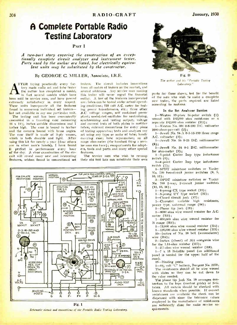
304 RADIO -CRAFT
A Complete Portable Radio Testing Laboratory
PART I
/I two -part story covering the construction of an excep- tionally complete circuit analyzer and instrument tester. Parts used by the author are listed, but electrically equiva-
lent units may he substituted by the constructor.
By GEORGE C. MILLER, Associate, I.R.E.
FTER trying practically every fac- tory made radio set and tube tester the author has completed a model, in fact several models which have
been sold to service men, and have proved extremely satisfactory in every respect. These units incorporate all the features found in numerous individual set testers - but not available in any one particular unit.
The testing unit has been conveniently assembled in a traveling case measuring 16 x 14V, inches outside dimensions and 7
inches high. The ease is bound in leather and the corners bound with brass angles. The case itself is made of 3 -ply veneer, which is both durable and light. After using this kit for nearly a year (four others are in other men's hands), I have found it perfect in performance every hour of the day. A close examination of the cir- cuit will reveal many new and interesting features, seldom found in conventional set
testers. The circuit includes innovations from all makes of testers on the market, and several additions. Any service in an n making this tester will never regret the financial outlay. A few of the features incorporated are: tubes can be tested under actual operat- ing conditions; 750 volt A.C. meter for test- ing power transformers, etc.; three other A.C. voltage ranges; self contained power plant; modulated oscillator for neutralizing, synchronizing and testing output; voltage and current tests of both plates in rectifier tubes; external connections for every piece of testing apparatus; tests and analyzes any set using any type or make of tube; handy carrying case; tube rejuvenator; an all range ohm -meter (the handiest thing a serv- ice man can have) ; compartments for adapt- ers, tools and parts and many other special features.
The service men who wish to revamp their old test kits can substitute their own
FOR 2 PLATE NORMAL RECTIFIERS POSITION
0 -3 -I5 -150 AND 0 -750 A.C. VM.
A.C. VOLTS
0 150
50 750
10.000 OHM RES. CUT DOWN TO ABOUT 8000 OHMS
NORMAL POSITION
TIP JACK FOR CONTROL GRID o-_._ (CAP) OF 5G5. h9 - 0
POSITION FOR S -G TUBES
D.C. VM. 0-9.200
AND 0 -BOO VOS
2
NORMAL POSITION
REVERSE METER
POSITION
UP POSITION
200 V. 8V.
e 80V
420000 OHMS
72.000 OHMS
600.000 OHMS
l 41/2 V. BATT.
WITH VAR TAPS FOR
O OHM-MTR O,GRID TEST
POSITION
NORMAL POS. - AOHM-METER 0 10 MA METER
<~ iZ OÑ o
OHMS ' TE M TERM
-o NORMAL
0
944 OHMS
TO USE VAR. RES.
EXTERNALLY
25 MA.
5 AMP POS
ABOUT 10' -
N2.18 BELL WIRE
1920000 0-25-250 MA. OHMS O-SA.
./11101111 2M 'M1sINEN11/s.11131M. BINDING - -_
POSTS
tT
200 B J BOO V. ON B
POSITION
8ó 80
ON L POS
-D C. VOLTS
Fig. 1
Schematic circuit and connections of the Portable Radio Testing Laboratory.
January, 1930
Fig. D
The author and his "Portable Testing Laboratory."
parts for those shown, but for the benefit of the men who wish to make a complete new tester, the parts required are listed according to sections.
In the Set Analyzer Section
1- Weston 10 -place bi -polar switch (1) wound with 192,000 ohm resistance or a sepal rate 192,0(10 ohm resistor (1t2);
1- Weston No. 301 0 -8 -200 D.C. voltmeter 1000 -ohms- per -volt (2);
1- Jewell No. 74-A 0 -3 -15 -150 three range A.C. voltmeter (3);
1-Jewell No. .54 0 -25 D.C. milliammeter (4);
1- Jewell No. 54 0-1 D.C. milliammeter for ohm -meter (5);
1 -5 -point Carter Lop type inductance switch (6);
1-4 -point Carter Imp type inductance switch (7);
4 -SPDT miniature switches or Taxlev No. 730 two-circuit junior switches (8, 9,
10, 11); 3-DPDT miniature switches or Yaxley
No. 760 2 -way, 2- circuit junior switches (12, 13, 14);
1-4 -prong CX type socket (15); 1 -5 -prong US- type socket (16); 1- Closed circuit jack (17) ;
1- Clarostat variable high resistance, power type, universal range (18);
1 -Phone tip jack (19); 1 -8000 ohm wire wound resistor for A.C.
meter (R1); 1- 600,000 ohm wire wound resistor for
B range (R3); 1- 72,000 ohm wire wound resistor (R4) ;
1- 120,000 ohm wire wound resistor (115) 10- Inches of No. 18 bell (annunciator)
wire (R6); 2- Inches (about) of .015 manganin wire
for the 1.14 -ohm resistor (117); 1 -2.7 -ohm wire wound resistor (118). 1 -7 x 15 Bakelite panel (an additional
panel is needed for the upper half of the Case).
19- Binding posts. 1-41/ volt "C" battery, Burgess No. 2370; The resistances should all be wire wound
with slides so they can be cut down to the value needed.
The phone tip jack No. 19 arranges con- nection to the tops (control grids) of S -G. tubes. All meters should be checked with known standards when possible. If correct resistances are available the check can be
dispensed with since the tolerance values employed in the manufacture of resistances are sufficiently close for radio service re- quirements.
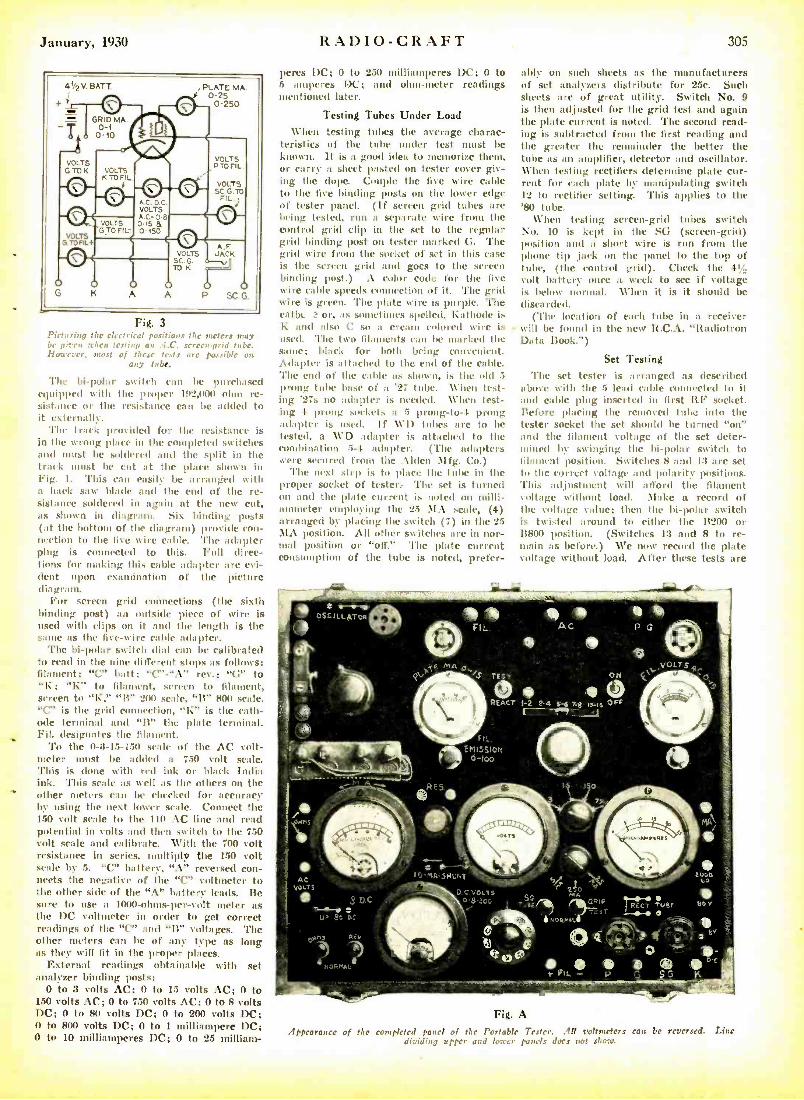
January, 1930 RADIO -CRAFT 305
Fig. 3 Picturing the electrical positions the meters may be given tchen testing an :l.C. serrennid tube. However, most of these tests are possible on
any tube.
'Pile bipolar switch can be purchased equipped with the proper 192,000 ohm re- sistonee or the resistance can be added to it externally.
The track provided for the resistance is in the wrong place in the completed switches and must be soldered and the split in the track must be cut at the place shown in Fig. 1. This can easily be arranged with a hack sow blade and the end of the re- sistance soldered in again at the new eut, as shown in diagram. Six binding posts (at the bottom of the d ia gr.um i) provide con- nection to the five wire cable. The adapter plug is connected to this. Full direc- tions for making this cable adapter are evi- dent upon examination of the picture diagram.
For screen grid connections (the sixth binding post) an outside piece of wire is used with clips on it and the length is the same as the five -wire cable adopter.
The Iii -polar switch dial can be calibrated to read in the nine different stops as follows: filament; "C" bait; "C " -"A" rev.; "Cr to "K; "Ih" to filament, screen to filament, screen to "K," "11" 2(H) scale, "B" 800 scale. "C" is the grid connection, K" is the cath- ode terminal and "11" the plate terminal. Fil. designates the filament.
To the 0 -3 -15 -150 scale of the AC volt- meter must be added a 750 volt scale. This is done with red ink or black India ink. This scale as well as the others on the other meters can be checked for accuracy by using the next lower scale. Connect the 150 volt scale to the 110 AC line and read potential in volts and then switch to the 750 volt scale and calibrate. With the 700 volt resistance in series, multiply the 150 volt scale by 5. "C" battery, "A" reversed con- nects the negative of the "C" voltmeter to the other side of the "A" battery leads. Be sure to use a 1000- ohms- per -volt meter as the DC voltmeter in order to get correct readings of the "C" and "B" voltages. The other meters can be of any type as long as they will fit in the proper places.
External readings obtainable with set analyzer binding posts:
0 to 3 volts AC; 0 to 15 volts AC; 0 to 150 volts AC; 0 to 750 volts AC; 0 to 8 volts DC; 0 to 80 volts DC; 0 to 200 volts DC; O to 800 volts DC; 0 to I milliampere DC; O to 10 milliamperes DC; 0 to 25 milliam-
peres DC; 0 to 250 milliamperes DC; 0 to 5 amperes DC; and ohm -meter readings mentioned later.
Testing Tubes Under Load When testing tubes the average charac-
teristics of the tube under test must be known. It is a good idea to memorize them, or carry a sheet pasted on tester cover giv- ing the clope. Couple the five wire cable to the five binding posts on the lower edge of tester panel. (If screen grid tubes are being tested, run a separate wire from the control grid clip in the set to the regular grid binding post on tester marked G. 'l'he grid wire from the socket of set in this case is the screen grid and goes to the screen binding post.) A color code for the five wire cable speeds connection of it. The grid wire is green. The plate wire is purple. The rani, ' or, as sometimes spelled, Kathode is K and also C so a cream colored wire is used. 'l'he two filaments cran be marked the saune; black for both being convenient. Adapter is attached to the end of the cable. The end of the cable as shown, is the old 5 prong tube base of a '27 tube. When test- ing '27s no adapter is needed. When test- ing 4 prong sockets a 5 prong -to -.1 prong adapter is used. If WI) tubes are to be tested, a WI) adapter is attached to the combination 5 -1 adapter. (The adapters were secured from the Ahem Mfg. Co.)
'l'he next step is to place the tube in the proper socket of tester. The set is turned on and the plate current is noted on milli- ammeter employing the 25 MA scale, (4) arranged by placing the switch (7) in the 25 MA position. All other switches are in nor- mal position or "off." The plate current consumption of the tube is noted, prefer-
ably on such sheets as the manufacturers of set analyzers distribute for 25c. Such sheets are of great utility. Switch No. 9 is then adjusted for the grid test and again the plate current is noted. 'l'he second read- ing is subtracted from the first reading and the greater the remainder the better the tube as an amplifier, detector and oscillator. When testing rectifiers determine plate cur- rent for each plate by manipulating switch 12 to rectifier setting. This applies to the '80 tube.
When testing screen -grid tubes switch No. 10 is kept in the SG (screen -grid) position and a short wire is run from the phone tip jack on the panel to the top of tube, (the control grid). Check the 41/2
volt battery once a week to see if voltage is below normal. When it is it should be discarded.
('l'he location of each tube in a receiver will be found in the new R.C.A. "Radiotron Data Book. ")
Set Testing The set tester is arranged as described
above with the 5 lead cable connected to it and cable plug inserted in first ItF socket. Before placing the removed tube into the tester socket the set should be turned "on" and the filament voltage of the set deter- mined by swinging the iii -polar switch to filament position. Switches 8 and 13 are set to the correct voltage and polarity positions. This adjustment will afford the filament voltage without load. Make a record of the voltage value; then the bi -polar switch is twisted around to either the 11200 or B800 position. (Switches 13 and 8 to re- main as before.) We now record the plate voltage without load. After these tests are
tg-%-
Fig. A
Appearance of the completed panel of the Portable Tester. All voltmeters can be reversed. Line dividing upper and lower panels does not show.
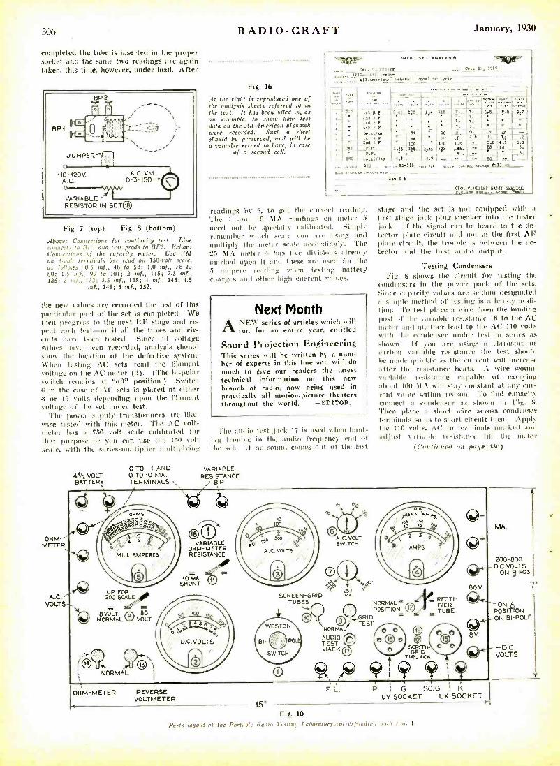
306
completed the tube is inserted in the proper socket and the saine two readings are again taken, this time, however, under load. After
110-120V. A.C. o
Fig. 7 (top) Fig. 8 (bottom)
Aboc: Connections for continuity test. Line connects to 1fí'1 and test prods to 11P2. Below: Connections of the capacity meter. Use VJf on 3 -vlt terminals but read on I50volt scale, as follows: 0.5 mf., 48 to 52; 1.0 mf., 78 to 80; 1.5 mf., 99 to 101; 2 mf., 115; 2.5 mf., 125; 3 mf., 132: 3.5 mf., 133; 4 mf., 145; 4.5
mf., 148; 5 mf., 152.
the new values are recorded the test of this particular part of the set is completed. We then progress to the next RF stage and re- peat each test -until all the tubes and cir- cuits have been tested. Since all voltage values have been recorded, analysis should show the location of the defective system. When testing AC sets read the filament voltage on the AC meter (3). (The bi -polar switch remains at "off' position.) Switch G in the ease of AC sets is placed at either :3 or 15 volts depending upon the filament voltage of tim set under test.
The power supply transformers are like- wise tested with this meter. The AC volt- meter has a 750 volt scale calibrated for that purpose or you can use the 150 volt scale, with the series- Itiplier multiplying
OHM-A METER
A.C. VOLTS
OTO 1. AND 41/2 VOLT 0 TO 10 MA. BATTERY TERMINALS s
di
+ OHMS
IRO a .
0 .
MILLIAMPERES
q04`
,CD UP FOR 200 SCALE
8 VOLT 80 NORMAL© VOLT
RADIO -CRAFT January, 1930
Fig. 16
:It time right is reproduced one of the analysis sheets referred to in the text. It has been tilled in, as an example, to show how test data on the a11- American Mohawk were recorded. Such a sheet should be preserved, and will be
a valuable record to have, in case of a second call.
LL
.:..,....
._.
14/. sn. ui_I,,:,rt.
' ::.
RADIO SET ANALYSIS
.... _nt. i, .t...t r.en tyr+^-------
f
. ..
.....1...........L..:.
I::: '!
'913ft' 1?2102:,
': : ' ,:-::k
a F. r zmlr.r
t 1;0 1 2,,t us i. 'r± I7-j7 5.e i p.s sw '
- tt--
ir a r . I 2r4 r
.
is ... 5
t.e
-irr .i.s ' 7. i.
1 12 `
J.e 4.7 1.1 2 i.P.
V.P.
.Lr t5 2.6 .:re :12
. 45. '. -- r .. _
; 5.
( - s. s ..r . .. -
, s.= - , - _ - . 80 I -. L .
.. , mil ... .. 95-115 ........ . ... ... . ...... ... .... ?Alas - _
aro. c.uluar. -RATIO $iSSlrlr. P.0.2m 5ae_ --r.e
readings by 5, to get the correct rending. The 1 and 10 m1A reading, on meter 5
need not be spccinlly calibrated. Simply remember which scale you :ire musing and multiply the meter Neale accordingly. 'l'he 25 M. meter 4 has five divisions already nmrked upon it and these are used for the .5 ampere reading when testing battery charges and other high current values.
Next Month ANEW series of articles which will
run for an entire year, entitled
Sound Projection Engineering This series will be written by a num- ber of experts in this line and will do
much to give our readers the latest technical information on this new branch of radio, nosy being used in practically all motion -picture theaters throughout the world. -EDITOR.
The audio test ,jack 17 is used tt hen hunt- ing trouble in the audio frequency end of the set. If no sound comes out of lile Inst
VARIABLE RESISTANCE
B.P.
stage and the set is not equipped with a
first stage lark plug speaker into the tester ,jack. If the signal taut be heard in the de- tector plate circuit and not in the first AF plate circuit, the trouille is between the de- tector and the first audio output.
Testing Condensers Fig. S shows the circuit for testing the
condensers in the power pack of the sets. Since capacity values are seldom designated a simple method of testing is a handy addi- l' . 'l'o test place a wire from the binding post of the van iable resistance 18 to the AC meter and nnothr lend to the AC 110 volts with the condenser under test in series as
shown. If you are musing a el:arostat or carhop variable resistance the test should be made quickly as the current will increase after the a'rsi ialiVe heats. .\ wire wound variable r,' ist:mcc capable of carrying about 1(0 t1A t. ill stay constant at any cur- rent value within reason. 'fo lind capacity connect a condenser as shown in Fig. 8.
'l'hen place a short wire across condenser terminals so as to short circuit them. Apply the 110 volts. A(' to terminals marked and adjust variable re,islauce till the meter
(Continued on Parut :I:1(i)
@O VARIABLE
014M-METER RESISTANCE
10MA. SHUNT
SCREEN -GRID TUBES
aii t y 25
MA.
NORMAL POSITION
9 GRID
R 1 TEST NORMAL A A
AUDIO TEST JACK
le= RECTI- FIER TUBE
O+
80V.
8v
.l
SCREEN. GRID
TI PJACN
OHM -METER REVERSE VOLTMETER
FIL. r i
P ; G SC.G. I K UY SOCKET UX SOCKET
MA.
200 -800 D.C. VOLTS
ON g POS.
7"
POSIT-fON ON BI-POLE
-D.C. VOLTS
15" Fig. 10
Parts layout of the Portable Radio 7 r,tuip Laboratory .correspondian with Fiat. 1.
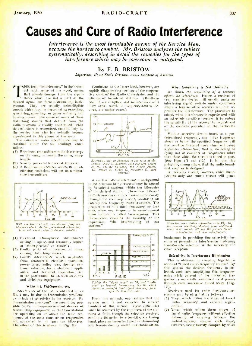
January, 1930 RADIO -CRAFT 307
Causes and Cure of Radio Interference Interference is the most formidable enemy of the Service Man, because the hardest to combat. Mr. Bristow analyzes the subject systematically, describing in detail the remedies for the types of
interference which may be overcome or mitigated.
By F. R. BRISTOW Supervisor, Home Study Division, Radio Institute of America
THE term "interference," in the broad - est radio sense of the word, means that sounds emerge from the repro-
- (ulcer which are not a part of the desired signal, but form a disturbing back- ground. They are usually unintelligible sounds which may be described as crackling, sputtering, squealing, or queer whirring and buzzing noises. The cause of many of these disturbing sounds that detract from the radio program is readily understood; while that of others is recognized, usually, only by the service man who has actually become experienced in this phase of the work.
'l'he causes of radio interference may be classified tender the six headings which follow: (1) Broadcast transmitters radiating energy
on the same, or nearly the same, wave- length;
(2) Nearby powerful broadcast stations; (3) A neighboring receiver which, in an os-
cillating condition, will act as a minia- ture transmitter;
0 Io 20 25
FIG 113
GOOD VOLUME
With one tuned circuit, Iwo stations fully ten kilocycles apart interf ere; a lessened separation,
as at B2, causes high continuous whistles.
(4) Electrical atutospheric disturbances arising in space, and commonly known as "atmospherics," or "static";
(5) Faulty parts of a receiver, at times, causing disturbing noises;
(6) Lastly, interference which originates from commercial electrical machines, power lines, trolley cars, elevated sys- tems, subways, home electrical appli- ances, and electrical apparatus used in the professional fields, such as X -ray and violet -ray equipment.
Whistling, Pig -Squeals, etc. Interference of the nature outlined under
No. 1 may be due to transmission problems or to lack of selectivity in the receiver. By "transmission problems" are meant the pos- sible faults in frequency- control devices of transmitting equipment, or that two stations are operating on or abut the same fre- quency at the same time, or on frequencies not separated by at least ten kilocycles. The effect of this is shown in Fig. 1B.
Conditions of the latter kind, however, are rapidly disappearing because of the coopera- tive work of the Radio Commission and the officials of broadcast stations. (Realloca- tion of wavelengths, and maintenance of a
more active watch on frequency- control de- vices, are major cures.)
100
75 -.--- VOLumE
50
25
(D
O p 00 3 WAVELEN32GTH
FIG.IO 600
Selectivity may be advanced to the point of dis- tortion; static is, however, thus excluded except on the narrow waveband the circuit passes. (A, static; .1?, surge; C, program; D, good
volume.)
A shrill whistle which forms a background to the program being received may he caused by broadcast stations within ten kilocycles Id the desired station. These two different radio- fregtteney currents pass simultaneously through the receiving circuit, producing an entirely new frequency which is audible. The production of this third frequency, or beat note, when frequency is superimposed upon :another, is called heterodyning. This phenoueenon explains the meaning of the expression, "the heterodyning of two stations."
Taking the "signal level" as 30, and "static level" as lettered. interference has the effect shown; a powerful local signal also may para-
lyze the first K.F. tube.
From this analysis, one realizes that the service man is not expected to correct troubles of this nature. These difficulties
t be removed by the engineers of the sta- tions at fault, though the selective receiver, confining its action to a- ten-kilocycle tuning loam', plays an important part in el' ating interference conning under this classification.
When Sensitivity Is Not Desirable At times, the sensitivity of a receiver
affects its selectivity. Hence, a receiver of very sensitive design will usually make an interfering signal audible under conditions where II less sensitive receiver will not re- produce the interference. 'l'he procedure to .adopt, when interference is experienced with an extremely sensitive receiver, is to reduce the sensitivity of the receiver by adjustment of the controls provided on the particular set.
With a selective circuit tuned to a pre- determined frequency, any other frequency above or below the specified frequency will find reactive forces at work which will cause a greater attenuation: that is, dwindling or dying out of currents at frequencies other than those which the circuit is tuned to pass. (See Figs. li) and 11:.) It is upon this principle, among others, that the radio broad- cast receiver is designed.
A receiving circuit, however, which incor- porates only one timed circuit will prove
f
o
F
0
A2 A
GOOD REPRODUCER
VOLUME
BARELY AUDIBLE-,
20 25 30 35 40
FIG. IC
With the same station separation as in Fig. 1B, the greater selectivity obtained from additional tuned R.F. circuits B2 and R3 permits louder
reproduction with less interference.
inadequate in providing fine selectivity be- cause of present -day- interference problems; ten -kilocycle selection is the necessity for clear reception.
Selectivity in Interference Elimination This is obtained Iw coupling together a
series of "tuned radio- frequency stages." By this system the desired frequency is se- lected, each tube amplifying this frequency only; while current of the undesired fre- quency is materially weakened as it passes through each successive tuned stage (Fig. IC).
Receivers used for radio broadcast re- ception may be classified as follows: (i) 'l'hose which utilize one stage of tuned
radio frequency, and variable regen- cra t ion.
(2) 'l'hose which utilize three stages of tuned radio frequency without effective balancing of coupling between the radio -frequency stages; each stage, however, being heavily damped by what
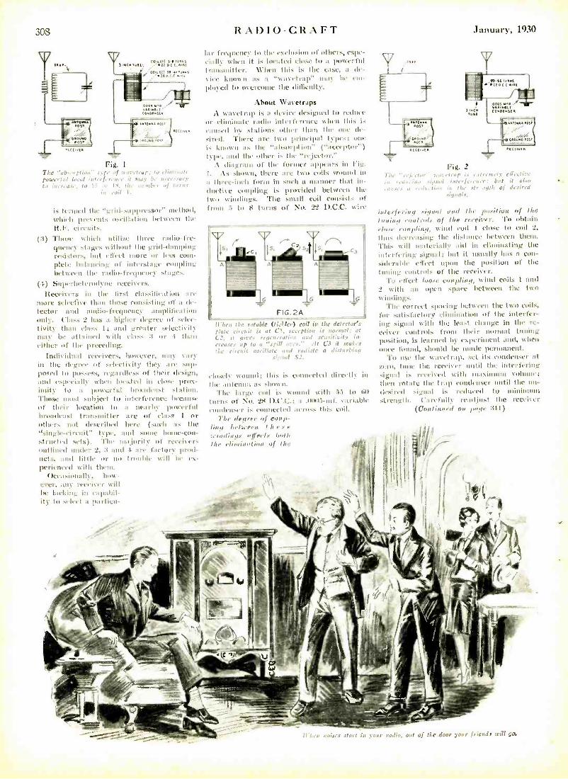
308
Fig. I Tire r, (rat :
po:cc . r,a1 irt,, ,, it rmow r carr 1, I.e. the ucmb,-r hrns m eJil 1.
(3)
is termed the "grill- suppressor" method, which pre% en' s oscillation between the lt.F. circuits. Those %chirp ulilirl' three radio -fre- quene\ stages %without the grid -damping resistors, but effect more or less com- plete balancing of iuterstagc coupling between the radio -frequency stages.
(1.) Suprhetermlynt receivers.
Itect'iver.s in the first classification are more selective than those consisting of a de- tector and audio -frequency amplification only. ('lass 'S has a higher degree of selce- tivity than class 1; and greater selectivity may Ile attained with class :3 or t than either of the preceding.
Individual receivers, however, may vary in the degree of selectivity they ant sup- posed to possess, regardless of their design, and cspetiall)' when located in close prox- imity to at powerful broadcast station. Those most subject to interference because of their location to a nearby p overfill broadcast transmitter are of class I or others not deseribed here (such as the "single- circuit" type, and sons home -con- structed sets). The majority of receivirs outlined under 2, 3 and f are factory prod - uets, and little nr no h'uulde Mill he tx- perieneed %with than.
(tceasi malty, how -
ever, any receiver will he lacking in capabil- ity to select a partiru-
RA1)IO -CRAFT January, 1930
I:u frequency to the exelusion of others, espr- eir,il when it is located close to at powerful transmitter. When this is the else, a de-
'ice known as a """"1"P" null' he ein
ployed to oyeITIMIC the tIitlieulty.
About W'avetraps
wavetrap is a device designed to reduce or eliminate radio interference when this is e:nlsetl by strut other than till' one de-
There arc two principal types; oar known as the "absorption" ( "aeeptor ")
I%lu, and the other k the "rejector.,' :\ diagram of the former appears in Fig.
I. As shown, there are two coils wound in a three -inch form in mull a manner that in- ductive coupling is pruviikl between the two windings. 'Pile small coil consists of from .i to F turns of No. 22 D.C.C. wire
illicit flic rntaólc (tüklcr) coil is Mc detector's plate circuit is at Cl, reception is normal: at i.2 it gives rigrnirati,n, mud sensitivity im errases up to a "spill over." ./t C3 it makes the , ni vit Jsi il/a te and radiait a disturbing
signal S3.
closely wound; this is connected direelly in the antenna as shown.
The large coil is wound with 55 to (ii)
turns of No. 28 I).('.('.: a .00115-inf. variable condenser is connected across this coil.
'l'Lr degree of ern/ti- ling loIra'ertt t h e s e
¡vndia !Is affects boll, lb, elimination of the
r Fig. 2
'1he njr.bn' :tavrt nip Is r.rt rrnrrly etitel ire .0
ir u'dr, and inlrrfneIlee: butt it also
, ors,: a t,'dr ,'glen in Ihr str .yrth of desired signals,
jotcrferinp .'lingot ,anal the i,nsiliot of Ibe Inning eo rit rol.a of the recri;v t'. 'Po obtain ,lu >,, i,rol,ling. N1i1111 coil I cluse to coil 2,
thus decreasing the distance between thons.
This will materially aid in eliminating the interfering signal; but it usually has a con - silerrhle effect upon the position of tic liming controls of the receiver.
To effect taos, e,otpling. wind coils 1 and 2 with an open space between the two windings.
l'hl' comt'a't spacing bctw.cen the two coils, for satisfactory elimination of the interfer- ing signal with the least change in the re- ceiver controls front their normal tinting position, is learned by experiment and, when once finuul, should be made permanent.
'Po use the wavetrap, set its condenser at zero, tune the receiver tortil the interfering signa is received with maxi mau tuluue: then rotate the trap condenser until the un- desired signal is reduced tu minims m strength. l'nrcfull) readjust the retei%cr
( ('Orel inn, d ,,i, la,oe 31.1)
When noises .tart in :aur radio. ad of fhe.door :
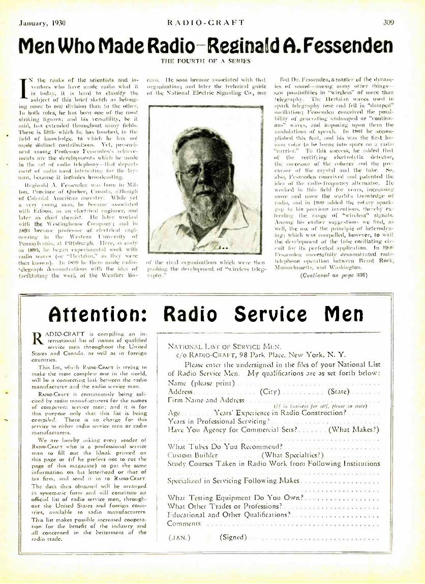
Ilntn:u t. l'Lill R l) IO-CR 12
Men Who Made Radio- Reginak1 A. Fassenden V the ranks of the scientists and in- ventors who have made radio what it is today, it is liard to classify the subject of this brief sketch as belong-
ing more to one division than to the other. In both roles, he has been one of the most striking figures; and his versatility, be it said, Ios tstcuded throughout tunny fends. There is little tvhicll he has tonehed, in the field of knowledge. to v.hich he has not ,node distinct cmttributious. Yet, pre -emi- nent among Professor ressendens achicte- menls are the developments which lie made in the art of radio telephony-that depart- ment of radio most interestimt. for the lay- man, because it includes broadcasting.
Reginald . \. 1'escnden was born in \lil- ton, Province of (Quebec, Canada, although of Colonial American ancestry. Whil yet a very young man, he became associated with Edison. as nut electrical engineer, and later as chief chemist. Ile later worked with the \Cestinghomse ('nutpan; and in 189:3 ntecaune professor of electrical engi- neering in the Western University of Pennsylvania, at Pittsburgh. IIir, as early
as 189:1, he began experimental work with radio ,rives (or 'Ilertziaii," as they were then known). In Ih11!I he there nude radio- telegraph demonstrations with the idea of facilitating the work of the Weather Bit-
THE FOURTH OF _1 'Fltll s
ream. Ile soon became arsotiuted Willi that oranization; and later the technical guide uif the National Electric Signaling Co., one
of the rival organizations which were then pushing the development of "wireless teleg raplty"
Attention: Radio RADIO -CRAFT is compiling an un-
ternational list of names of qualified service men throughout the United
States and Canada. as well as in foreign countries.
This list, which RADIO-CRAFT is trying to make the most complete one in the world, will be a connecting link between the radio manufacturer and the radio service man.
RADIO -CRAFT is continuously being soli- cited by radio manufacturers for the names of competent service men; and it is for this purpose only that this list is being compiled. There is no charge for this service to either radio service men or radio manufacturers.
We are hereby asking every reader of RADtoCRAFr who is a professional service man to fill out the blank printed on this page or (if he prefers not to cut the page of this magazine) to put the same information on his letterhead or that of his firm, and send it in to RADIO- CRAFT.
The data thus obtained will be arranged in systematic form and will constitute an official list of radio service men, through- out the United States and foreign coun- tries, available to radio manufacturers. This list makes possible increased coopera- tion for the benefit of the industry and all concerned in the betterment of the radio trade.
kul Ill. Fessenden, a master of the dynam- ics of sound -among many other things - sat possibilities in "wireless" of more than telegraphy. The Ilertzimt waves used in spark telegraphy rose and fell in "damped" oscillation; I'esscntlen conceived the possi- bility of generating undamped or "cuutimu- tat,' tvavts, and imposing upon their the modulations of speech. ln nail he accom- plished titis Peal, anal luis tris the first hu- man voice lu be borne into .Dace mn it radio "carrier. To Ibis sneeess, he :Added that of the rectifing elect roIvtie detector, till. successor ut' the toherer and the pre- cursor of the crystal and the tube. So.
also, l'essenden conceived :nul patented the idea of the radin- fretptency alternator. Ile worked in this field for years, increasing more and noue the world's knowledge of radio, and in 1606 added the rotary spark- gap tu his pre ions inventions, thereby ex- tending the range of "wireless' signals. .loo ng luis earlier suigu -.t oui'. we hind, as
well, the use of the principle of heterodyn- ing; which was compelled, however, to tuait HID let clopmcnt of the tulle oscillating cir- cuit for its perfected application. In 190ä
l'essenden successfully demonstrated radio telephone operation between Brant Ittek. Massachusetts, and Washington.
(Continued nu pape 336)
Service Men NATIONAL LIST OF SERVICE MEN,
c/o RADIO- CRAFT, 98 Park Place, New York, N. Y. Please enter the undersigned in the files of your National List
of Radio Service Men. My qualifications arc as set forth below: Name (please print) Address (City) (State) Firm Name and Address
(If is t,usiness for self, please so stale)
Age Years' Experience in Radio Construction? Years in Professional Servicing' Have You Agency for Commercial Sets? (What Makes ?)
What Tubes Do You Recommend? Custom Builder (What Specialties ?) Study Courses Taken in Radio Work from Following Institutions
Specialized in Servicing Following Makes
What Testing Equipment Do You Own? What Other Trades or Professions' Fducational and Other Qualifications' Comments
(.IAN.) (Signed)
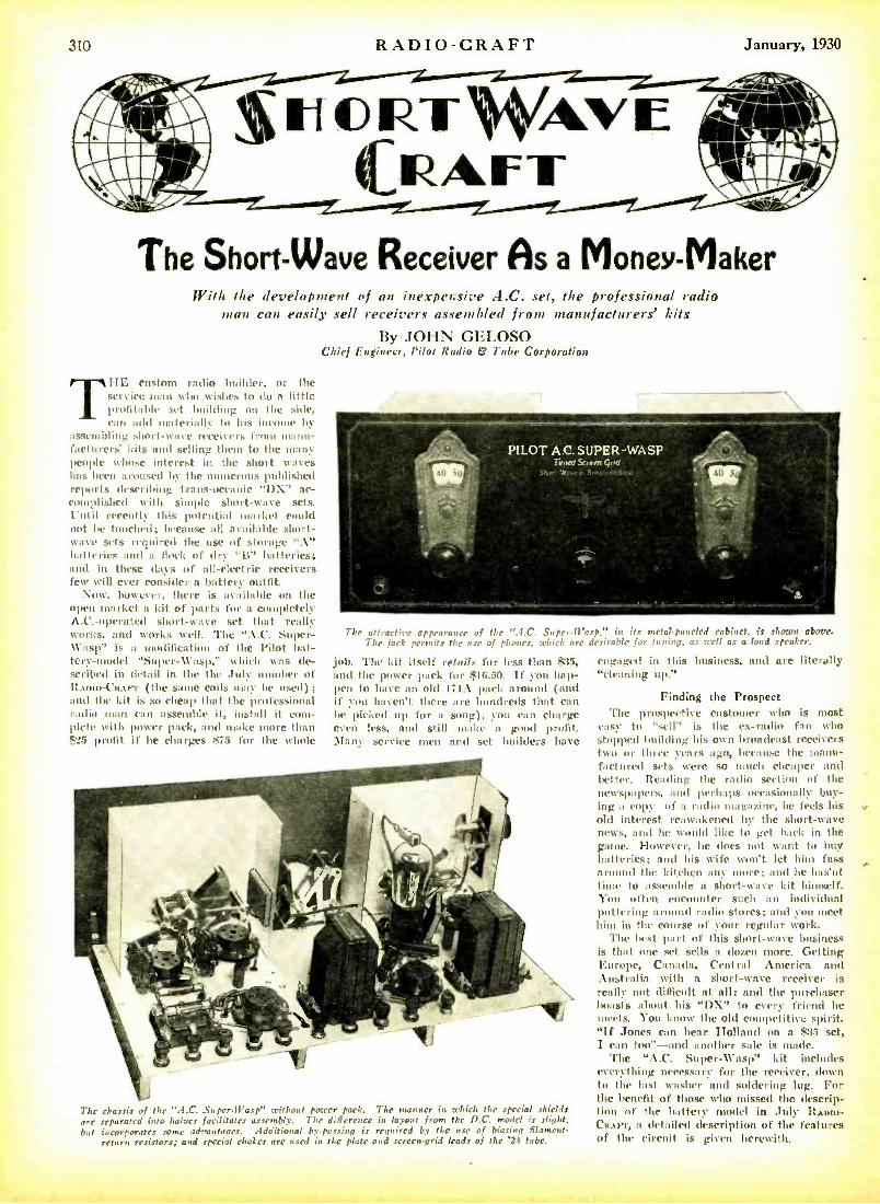
310 RADIO- CRAFT January, 1930
The Short -Wave Receiver As a Money-Maker With Nie development of an inexpensive A.C. set, the professional radio
man can easily sell receivers assembled from manufacturers' kits
By JOHN GELOSO Chief Engineer, Pilot Radio & Tube Corporation
TDE custom radio builder, or the service twin shu wishes to do a little profitable set Inuikling on the side, can add materially to his income by
assembling short -wave receivers from manu- facturers kits and selling thew to the many people whose interest in the short waves has been auoused by the numerous published reports describing trans -oceanic "I)\" ac- complished with simple short -wave sets. Until recently this polcntial market could not be touched; because all available short- wave sets required the use of storage "A" batteries and a flock of dry "ii" batteries; and in these days of all- electrie receivers few will ever consider a battery outfit.
Now, however, there is available on the open market a kit of parts for a completely A.C.-operated short -wave set that really works, and works well. The "A.C. Super - W'asp" is a modification of the l'ih,t bat- tery -model "Super- Wasp," which was de- seribed in detail in the the Jul- number of ItAnto -CRAFT (the same coils way be used); and the kit is so cheap that the professional radio man can assemble it, install it com- plete with power pack, and make more than "5 profit if he charges $75 for the whole
The attractive appearance of the ".1.C. Super -Wasp," iaa its metal -paneled cabinet. is shown above. The jack permits the use of phones. which arc desirable for tuning, as well as a loud speaker.
job. The kit itself retail. for less than $35, and the power pack for :f16.50. If you hap- pen to have an old 171A pack around (and if you haven't there are hundreds that can be picked up for a song), you can charge even less, and still make a good profit. Many service men and set builders have
The chassis of the "A.C. Super.IVasp" without power pack. The manner in which thc special shields arc separated into halves facilitates assembly. The difference in layout from the D.C. model is slight, but incorporates some advantages. Additional by- passing is required by the use of biasing fflament-
return resistors; and special chokes arc used in the plate and scrcemgrid leads of the '24 tube.
engaged in this business, and are literally "cleaning up."
Finding the Prospect The prospective customer who is most
easy to ',o-ll" is the ex-radio fan who stopped building his own broadcast receivers two or three Fears ago, because the manh- factured sets were so much cheaper and better. Reading the radio section of the newspapers, and perhaps occasionally buy- ing a copy of o radio magazine, he feels his old interest reawakened by the short -wave news, and he would like to get hack in the gaine. However, he does not want to buy batteries; and his wife sori t let him fuss around the kitchen any mare; and he has'nt time to assemble a short -wave kit himself. You often encounter such cur individual puttering around radio stores; and you meet him in the course of your regular work.
The best part of this short -wave business is that one set sells a dozen more. Getting Europe, Canada, Central America and Australia with a short -wave receiver is really not difficult at all; and the purchaser boasts about his "DX" to every friend he meets. You know the old Competitive spirit. "If Jones can hear Holland on a $35 set, I can too" -and another sale is made.
The "A.C. Super -Wasp" kit includes everything necessary for the receiver, down to the last washer and soldering lug. For the benefit of those who missed the descrip- tion of the battery model in July RADIO-. CRAFT, a detailed description of the features of the circuit is given herewith.
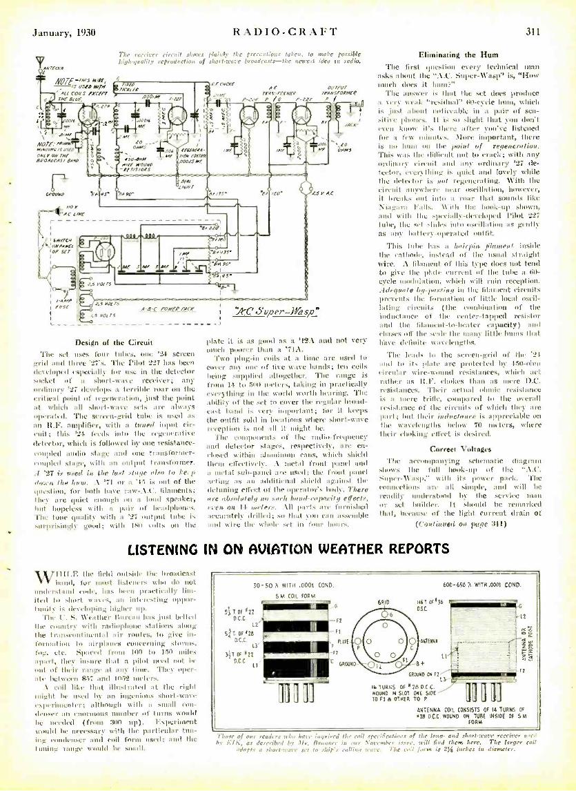
January, 1930
AN'E.f 1'A
41
0
NOTE--'"*"' /s OSPO »MA "lO CONS 'WW1 /(
RADIO-CRAFT 311
The cutter eireit .sloes plainly tire precautions taken, to make possible Li,drgn alit reproduction. of shori-MI :r b,-oadrasts -111C u/.rcd idea in radio.
4
' A[[ NE A( Of .000/
LFCNONE
_"1"f"..
AF OU7PU7 reAN:.IreMEE 7PANSFOFAIE.P
P P-727 P I
o a 6r00/6
s/. NOTE: To Ir/NO[NG /S USED
ON[ 1, ON rNE BROADCAST EA,O
Ml -= [ ONNS
IJ0.0 M WIPE MOUND -St 5/5705S
ÓPaUNO
.006 ME
Pf6EAEtA- NON CaV/
00075 MF
ó /Ml ,G06 MF
ti
454 ."6
n/Al /aìN7
E /f+ 00'
z.ssours
I,S YJETS
45 Vv[T5
s4.01".21111r e. ¿till
7=f =MF .r=
Ile
o
"e` `ów`r RICA' :4'C.SLper-Wasp.
Design of the Circuit The set tues four tubes, one '2i screen
_rid and Ilnrc'27's. 'l'Ire l'ilot 227 has been dis eloped especially for use in the detector socket of i shnrl -wave receiver; ant* ordinary '27 develops a terrible roar or the critical point of regeneration, just the point at whirl' all short -wave sets are always operated. The wrein- grid tube is used as
an 1l.F. amplifier, with a tinned input cir- cuit; this 'Yi feeds into th, regeurrative detector, which is followed by one resistance - coupled audio stage and une transformer - cuupled stage, with an output transformer. .1 '27 ix used in. the Lax/ .stage also to ke. p dear«« the hunt. A '71 or a '1:5 is out of the question, far botte have raw- . \.l'. filaments; they are quiet enough on a loud speaker, but hopeless with a pair of beadphoncs. The tome quality with n s 27 output tube is surprisingly good; with ISo lulls on the
`1[
Y. Ae
20 ONMJ
plate a is as good as a '12A and not very much p(rcer than a 11:\.
l'wo plug -in coils at a Livie are used to cover any one of lice heave bands; ten coils being supplied altngilheu'. The range is from It tu Su NI meters, taking in practically everything in the world worth hearing. 'Ploc
ahiliiy of the set to cover the regular broad- cast band is very important; for it keeps the outfit 6u1d in locations where short -wave exception i. not all it (night be.
l'he cnlnlloncuts of the radio -frequency and detertur stages, respectively, are en- closed within aluminum canes, which shield thenI eIrectiyel. :\ metal Inuit panel and a metal sub -panel :p.e. used: the front panel acting as an udditi+ nul shield against the del lining effect ut' the operator's body. There rF re nbxula I CI an ..vo'b hot rd -rn pntilt¡ Pgeelx, even on 1I no/(v-.s. All parts are furnished accurately drilled; so that you can Hssruuhle
nad wire the NV11ar11 set in tam (runes.
Eliminating the Hum The first question every technical man
asks about the "AA'. Super -\\'ashy is, "IIow much does it hunt:'
The answer is that the set does produce it Very weak "residual" l70- cycle hurt, which is just about noticeable in a pair of sen- sitise phones. It is so slight that you don't even know it's there after You've listened for :t few Mille it's. .Mare important, there is mu Iruun 1111 the point of regeneration. This tans the difficult nut to crack; with any ordinary circuit and any ordinary '27 de- tector, ccrrythiug is quiet and lovely while the detector is not regenerating. With the circuit anywhere near oscillation, however, it breaks out into a roar that. sounds like /toga ra Palls. \\ ill Ihr hook-up shown, and with the specinll- denJoped Pilot 227
tube, the set slides into oscillation as gently as any battery- operated outfit.
This tube has a hairpin Jilttnuut inside the cathode. inslrsul of the usual straight wire. .A Idmnent of this type does not tend to give the plow current of the tube a 60- cycle modulation, which will ruin reception. ;We-gaol, bq- pnx..inq in the filament circuits prevents the formation of little local oscil- lating circuits (the conrhin:ttion of the inductance of the center -tapped resistor and the lilauat -to -hider capacity) and chases oft the scale the many little hums that Nave definite wavelengths.
The leads to the serien -grid of the '2I and to its plate arc protected by 150 -ohnl circular wire -wound resistances, which act
rather as 11.F. chokes that' as uuere 1).C.
resistances. '/'heir actual ohmic resistance is a mere trifle, campared in the overall resist:owe of the circuits of which they are l :net: hat their indeeleeev is appreciable on the wavelengths below 70 totters, where their ehokin_ eti'ret is desired.
Correct Voltages
The accompanying schematic diagram shows the full hook -up of the ":\.('. Super -\Carp;' with its power park. The connections are all simple, and will he readily understood by the serviec man or set builder. It should be remarked that, because of the light current drain of
(continued on page 341)
LISTENING IN ON AVIATION WEATHER REPORTS
7I111.E the field outside the lraadeist VV band, for unut listeners who do not
understand rode, has been practically lim- ited lo short wanes, an interesting oppor- tunity is develnlrin_ higher up.
The I'. S. \Cealhrr (torero« has just belled the country with radiophone stations along the transcontinental air routes, to give in- foruation to airplanes concerning storms. log., etc. Spaced front 100 to 150 miles apart, they insure that a pilot need not be
out of their range at any time. 'l'hty oper- :dr óelween S. ; and 11152 meters.
.\ roil like that illustrated at the right eight be used by an ingenious short.%v u e
experimenter; although with :I small von - denser an enormous number of turns would be needed (from 300 up). I :s per iiiwtit would be necessary with the particular tun- ing condenser and coil form used and the tuning range would be small.
30-50 A WITH .0001 COND.
SM COIL FORM
9} T.OF A72 D.C.C.
L2
SIT OF 028 D.C.C.
L3
3?1 OF 022 D.C.0
11
6
-FI - FI
FLAIE
F1
GROUND
GRID 1461 OF 136
600-650 A WITH.0001 COND.
L1
GROUND ON Fi- ll lb TURNS OF 028 D.C.C. WOUND IN SLOT ONE SIDE TO FI A OTHER TO P.
G
12
[c n o 4 i° i á
FI
ANTENNA COIL CONSISTS OF 14 URNS OF
N28 D.C.L. WOUND ON TUBE INS( E OF S M
FORM
Those of war readers :rho have inquired the coil speeiCeatbws of the long and short-wave receiver i.'rd by K/ K, as described by .Tlr. Rrrnorrr in oar . \'nrrruhrr igsee. win find them here. The larger coil
adapts a short-wave set to xhip's r11/inn Wane. '/Lc rein (.non is 2% inches in diameter.
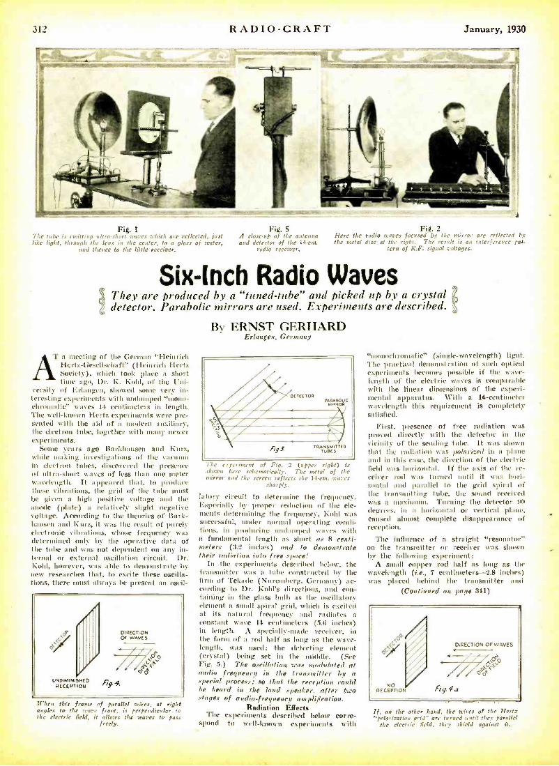
312 RADIO -CRAFT January, 1930
Fig. 1
The tube is emitting ultra -short v.
t
res c.hich are reflected, just h like light, throug the lens in the center, to n glass of water,
and thence to the little receiver.
Fig. 5 A chose -up of the antenna and detector of the 14 -em.
radio receiver.
Fig. 2 Here the radio waves focused by the mirror arc reflected by the metal disc at the right. The result is an interference pat-
tern of R.F. signal voltages.
Six -Inch Radio Waves They are produced by a "tuned -tube" and picked up by a crystal detector. Parabolic mirrors are used. Experiments are described.
By ERNST GERHARD Erlangen, Germany
I' a meeting of the German Hertz Hertz- Gescllschaft" (Heinrich ieh Hertz Society), which took place a short time ago, Dr. F. Kohl, of the Uni-
versity of Erlangen, showed some very in- teresting experiments with undamped "mono - chromatic" waves 14 centimeters in length. 'l'he well -known !hertz experiments were pre- sented with the aid of a modern auxiliary, the electron tube, together with many- newer experiments.
Some years ago Barkhausen and Kurz, while making investigations of the vauuut in electron tubes, discovered the presence of ultra -short waves of less than one peter wavelength. It appeared that, to produce these vibrations, the grid of the tube must be given a high positive voltage and the anode (plate) a relatively slight negative voltage. According to the theories of Bark - hausen and Kurz, it was the result of purely electronic vibrations, whose frequency was determined only by the operative data of the tube and was not dependent on any in- ternal or external oscillation circuit. Dr. Kohl, however, was able to de strafe bv new researches that, to excite these oscilla- tions, there -t always be present an oscil-
UNDIMINISHED
, op
oc
DIRECTION Or WAVES
ÌI 4 RECEPTION 9'
trite, this frame of parallel wires, at right angles to the ware front, is perpendicular f' the electric field, it allows the trams to pass
freely.
A4' DETECTOR
M A RORLIC /A_ IIIII - I
1rg3 iR TUBES TER
The experiment of Fig. 2 (upper right) is shown here srhnnat ically. The metal of the mirror and the screen reflects the 14 -cut. tiaras
sharply.
latory circuit to determine the frequency. Especially by proper reduction of the ele- ments determining the frequency. Fold was successful, under normal operating condi- tions, in producing undamped waves with a fundamental length as short as R centi- meters (3.2 inches) and to demonstrate their radiation into free space!
In the experiments described below, the transmitter was a tube constructed liv the firm of 'fekade (Nuremberg. Germany) ac- cording to Dr. Kohl's directions, and con- taining in the glass bulb as the oscillatory element a small spiral grid, which is excited at its natural frequency and radiates a constant wave 14 centimeters (5.6 inches) in length. A specially -male receiver, in the form of a rod half as long as the wave- length, was used; the detecting element (crystal) being set in the middle. (See Fig. 5.) The oscillation was modulated at audio frequency in the transmitter by a special process; so that the reception could be heard in the load speaker, after two stages of audio -frequency amplification.
Radiation Effects The experiments described below corre-
spond to well -known experiments with
"umnocbromatic" (single-wavelength ) lignt. 'flic practical demonstration of such optical experiments becomes possible if the wave- length of the electric waves is comparable with the linear dimensions of the experi- mental apparatus. With a 14- centimeter wavelength this requirement is completely satisfied.
First, presence of free radiation was proved directly with the detector in the vicinity- of the sending tube. It was shown that the radiation wa, fn,huri_ed in a plane and in this ease, the direction of the electric field was horizontal. If the axis of the re- ceiver rod was turned until it was hori- zontal and parallel to the grid spiral of the transmitting tube, the sound received was a maximum. Turning the detector 93 degrees, in a horizontal or vertical plane. caused almost complete disappearance of reception.
'l'he influence of a straight "resonator" on the transmitter or receiver was shown by the following experiment:
A small copper rod half as long as the wavelength (i.e., 7 centimeters -2.8 inches) was placed behind the transmitter and
(Continued on page 311)
Op
NO I
RECEPTION
DIRECTION Or WAVES - r fig. la
oc
If, on the other hand. the wires of the Hertz "polarization arid" are turned until they parallel
the electric field, they shield against it.

January, 1930 RADIO-CRAFT 313
Short -Wave Stations of the World
fillo- Meters cycles 14.50 20,680 -....Monte Grande, Argentina. after 10:30
p. m. Telephony with Europe. 11.81 20.200 -DG W. Moen. Germany. 2 to 9 p.m.
Telephony to Buenos Aires. 15.03 19,950 -L8G, Monte Grande. Argentina. From 9
a.m. to 1 P.m. Telephony to Paris and Moen (Berlin).
-01H, Nauen, Germany. 15.50 19,350- Nancy, France. 4 to 5 p.m.
-FW3. Paris, France. Front 10 a.m. Tale- phony to Monte Grande (Buenos Aires).
-VK2ME. Sydney, ,Australia.
15.85 18,920 -XDA, Mexico Pity. \tex. 12:30 to 22:30 p.m. 15.91 18.810 -PLE, Iandoeng, Jar a. Broadcasts Wed.
8:40 to 10:40 a.m. Telephony srlth Kuot- wiik (Amsterdam).
1.1.10 18,620 -GBJ, Itodmin, England. Telephony with Jluut real.
l0.10 18,6220 -PCK, Kouhdjk, Holland. Dally from 1 to G :30 a.m.
10.11 18,610 --GBU, IWgby. England. 16.35 15.350- WHS. Deal Reach, N. J. Transatlantic
telephony. ]5,,38 18.310 -GBS. Rugby. England. Telephony with
New York. General l'ostoffi.e. London. 16.50 18,170 -CG A, Drummondville, Quebec. Canada.
Telephony to England. Canadian Marconi Co.
10.51 18.130- GBW, Rugby, England. 16.57 18.120 -- G K, Rugby. England. 16.01 18,050 - KOJ. Itolinas. Calif. 16.80 17,850- PLF. Itandurng. .lava ( "Radio Malabar"),
{Works with Holland. 10.88 17,770 -PH 1. 1kí1 zen, Holland. Ream station to
Dutch colonies. Broadcasts Mun.. Wed., Thun.. Frl. N to I1 a.nl. N. W. Philips Radio. Amsterdam.
1490 17,740 - HSI Pl. Bangkok. Sian. itroadrasts 9 t0 11:30 a.m.
17.20 17,440- Natte)). Germany. 17.34 17.300 -W2XK, Schenectady. N. Y. Tues., Thurs..
Sat. 12 to 5 p.m. General Electric l'o. 18.40 16,300 -PCL, Kootwijk, Holland. Works with
Bandoeng from 7 a.m. Netherland State Telegraphs.
18.56 16,150 -GBX. Rugby. England. 18.75 15,990 -....Saigon, Indo- China. 18.80 15,950 -PLG, Iandoeng. Java. Afternoons. 19.56 15,310- W2XAD, Schenectady, N. Y. Broadeasls
Sun. 2:30 to 5:40 p.m.. Tues.. Thurs. and Sat. noon to 5 p.in.. Frl. 2 tu 3 Rm.; besides relaying WOY "s evening program on Mon. Wed.. Fri. and Bat. evenings. Gen- eral Electric Company.
19.60 15,300 -.... Lyngby. Dennmrk, Experimental. 211.00 14, 900 -T F Z S H. Ireland. 20.50 14,625 -W8X F. Pittsburgh. Penna. 20.00 14.420 -VPD, SOS a, Fiji Islands. 22.20 13,500 -.... Vienna, Austria. 22.38 13,400 -WND. Deal Beath. N. J. Transatlantic
telephony. -2.59 13.050 --W2X AA, Moulton, Mo. Trairont )amie
telephony. 23.35 12,850 - W2X0, Schrned atty. N. Y. Antipodal
program 9 p.m. Mon. to 3 a.m. Toes.; noon to 5 p.m. on Tues., Thurs. ,old Sat. General
5 Io.
-W6XN. Oakland. Calif. Relays KGO from it p.m., Mon., Wed., Thurs.. to 2:45 a.m. Tues.. 3 a.m. Fri., 4 a.m. Sunday. Gen- eral Electric Co.
24.11 12.280 -GBU, Rugby, England. 21.50 12,240 -F W. Ste. As1se (Pans) France. Works
Sumo- ore.. hula -China and Jasa. Oit 9 Ain to 1 lt.nt.. and oilier hours.
-KIXR, Manilla. P. I. -GBX, Rugby. England.
24.68 12.150 -B BS. Rugby, England. Transatlantic phone to Deal, N. J. (New York).
25.10 11,010- ....Zeesen. Germany. Tests of new Super- [toner broadcasters.
25.10 11,800 -WBXK. E;ust Pittsburgh, Pa. Relay's K UK .% after 6 p. u;. Tues. and Thurs. from 5 to 7 Westinghouse Meet rie Co.
25.53 11.750 -G5SW, Chelmsford. England. Relays ILO tontknl. 2 Ion - p.m.. experimental trans- mission from 7 to 9 p.m. and 7:311 to 8 :30 a.m.. and tests with \V2XO 12 to 1 p.m. NI on. and Thurs. Silent Sat. and Sun. Brit ish Broadcasting Co.
25.50 11,710 -CJRX. Winnipeg. Canada. 5:30 to 6 p.m. daily. Bun. 1 to 2 p tit. Relays CJR V. James Richardson & Sons, Ltd.
2 r,8 11,870 -K10, Kahului. Hawaii. 26.00 11,530 --CG A. Drummondville, Canada. 211.10 11.490-G BK, Rugby, England. 25.22 11.430 -0HC. Nauen, Germany (lterlht) Weekdays
after 5. Sun. after 9 p.m. 25.70 11,230 -WSBN. SS. "Lys lathan" and A. T. &
T. telephone rn ))
nerd Inn.
27.00 11,100 -EATH, Vienna. .Austria. Mon. and Thurs., 5:30 to 7 it. m.
27.27 11.000- ..Posen, Poland. Mon. and Thun. 5 to 0 p.m. New cation testing.
All Schedules Eastern Standard
Time: Add 5 Hours for Greenwich Mean Tiene.
Hilo- Meters cycle, 27.80 10,780 -PLR, Itantloeng, Jara. Works with Hol-
land and France weekdays from 7 a.m.; somet hues after 9 :30.
25.00 10,710 -VAS, Glare Bay, N. S.. Canada 5 a.m. to 2 p.m. Canadian Marconi Co.
28.20 10.630 -PLE, Itandueng, Jas a. Tests with Australia. 25.50 10,5111- -RDRL, Leningrad. U.S.S.R. (Russi) 28.80 10.410 -V K2M E. Sydney,' Australia. Irregular. On
Wed. after 6 urn. Amalgamated Wireless of Australia, Pennant Hills, N. S. %V. -K ES. Dolinas. Calif.
30.00 9.905 - .... Posen. Poland. 30.15 9,94o -GBU, Rugby, England. 3u.20 9,0311 -W2XU, Long Island City, New York. 30.50 9,830- N RH. Ilere,lia. Costa Idea. 10:30 to 11:30
pin. Amami)) Cespedes Marin, Apartado 40. 30.04 9,790 --GB W. Rugby. England. 311.75 9,750- %gmn, France. Tues. and Frl., 5 to
6:15 P.m. 31.00 0,680 -710, Nairobi. Kenya. Africa. 11 a.m. to
2 p. to. Relays (15Sí\', Chelmsford, fre- quently from 2 to 3 to nt.
Monte Grande. Argentina, works Nauen irregularly after 10::30 p.m.
31.223 0.600 -LGN, Bergen, Nnnray. 31.26 9,590 -PC1, llilversnnl. Holland. English programs
Thum. and Fri. from 7 to 9 p.m., Sat. from 5 to 7 a.m. Other languages, Thurs. 1 to 3 a.m., Fri. midnight to 4 a.m. - Sat. 1 to 7 a Ill. N. V. Philips Radio, Eind- hoven, Holland.
3128 9.580- VS 2FC, Sydney. Australia. Irregularly after 4 a.m. N. S. \S'. Broadcasting Co.
-VPD. Suva, Fiji islands. 31.30 9,550- . 7,eesen. Germany. Projected new station. 31.48 9,530- W2XAF, Schenecadv, New York. Mon..
Tues., Thurs. and Sit. nights. relays WGY from f, stn. General Electric Co.
-WOX A, Denver. Colorado. Relays EGA. - . Ilelsingfors, Finland.
(NOTE: This list is compiled from many sources, all of which are not in agreement, and which show greater or less discrepancies; in view of the fact that most schedules and many wave- lengths are still in an experimental stage; that daylight time introduces confusion and that wavelengths are calculated differently in many sched- ules. We shall he glad to receive later and more accurate information from broadcasters and other transmitting organizations, and from listeners who have authentic information as to calls, exact wavelengths and schedules. We cannot undertake to answer readers who inquire as to the identity of un- known stations heard, as that is a
matter of guesswork; in addition to this, the harmonics of many local long - wave stations can be heard in a short wave receiver. -Editor.)
31.56 9,500- VK3LO. Melbourne. Australia. irregular. I lroadrasl log Co. of Australia.
-OZ7RL, Copenhagen. Denmark. Around 7 p.m.
32.00 9,375- EH9OC, (terne, Switzerland Mon.. Tues., Sat. 3 to 4 p.m
-0Z7MK, Copenhagen, Denmark. Irregular after 7 p.m.
32.13 9,330 -CGA. Drummondville, Canada. 32.40 9.250 -GBK. Rugby, England. 02.50 9.230 -FL. Paris. France (Eiffel Tower) Time
signals 3:56 a.m. and 3:56 p.m. -VK2BL, Sydney, Australia.
32.59 9,200 -13218, Rugby. England. Transatlantic pitone.
Meters cycles cycle, 33.26 9,0111 -GBS, Rugby. England. 33.70 8.900 -....Posen, Poland. Tests MoD, and Mts.
6 to 7 p.m. 31.50 8.500- W2XAC. Schenectady. New York 34.74 8,630 -WOO, Deal. N. J.
35.00 8,570 -H RCS. Manizales, Colombia. 35.48 8.450 -WSBN. SS. "Leviathan." 37.02 8,100 -EATH, Clouta, Austria. Mon. and Thurs.
5:30 to 7 p.ln. -HMIs. Bangkok. Siam. Tues. and Fri.
9 tu 11:30 a.m. 37.80 7,930 -00A, nocherita. Germany. I to 3 p.m.
Relrhiwstzentralauu, Berlin. 38.80 7,770-PCL. Kootwijk, Rolland 9 a.m. to 7 p.m. 39.98 7.500 -AFK Doeberitz. Germany.
-TFZSH, Iteykiac 1k, I; eland. -EKIZZZ. Danzig (Free State).
40.20 7,450 -YR. Lyons. France. Daily except Sun.. 11:311 Y.m. to 12:30 p. nt.
41.00 7.310 -....Paris. France ( "Radio Vitus") Tests.
41.50 7.220-....Zurich, Switzerland. Sat. 3 to 5 Sta. 41.70 7,190 -6AG, Penh. West Australia. Between
0:30 and 11a.m. 42.12 7,230- 027RL. Copenhagen. Denmark. Irregular.
Around 7 p.m. 43.00 6.870-EAR 110, Madrid, Spain. Tues. and Sat..
5:30 lo 7 p.m. 43.50 6.900 -DMA, ]toue. Italy. Sun, noon to 2:30 p.m.
43.68 6,860 -VRY. Cenrgetmvn, Itritlsh Guiana. Wed and Sun., 7:15 to 111:15.
44.00 6,020 -XC 51, San Lazar,, Mexico. 3 a.m. and 3 p.m.
47,00 6,61111 -.....;..clin, Germany. 45.20 6,6:1.: -WSBN. SS. -Les lat hap." 46.05 6.515 -WOO, Deal. N. J. 47.00 6,380- CT3AG. Funchal, Madeira Island. Sat.
after 10 p.m. 48.80 6,140 -KERN. NI and la. P. I. 49.02 6.120- -W2XE, New York City. Relays WABC.
Allant it Broadcasting Co. 49.:4 6.080- W2XCX, Newark, N. J. Relays WOR. 49.40 6,070 -UOR2, Vienna, Auiria. Testing Tues. and
Thurs., 8:10 to 'J :10 a.m. West. and Sat. after O p.m.
49.50 G,0(0- W8XAL, Cincinnati. Ohio. Relays WLW. -W9XU, Council Bluffs, Iowa. Relays KOIL.
49.70 6,030- W2XAL, New York. N. Y. 49.80 6,1120 -W9XF, Chicago. Ill. 50.00 6,000- EA125. Itarce Iona. Spain. Sat. 3 to 4 p.m.
-RF N. Moscow, Russia. Tues., Thurs., Sat. 8 W
-SAD, O
K a .m
rg, Sweden. -Eiffel rower, Paris, France Testing 6:30
to 6:45 a.m., 1:13 In 1:30, 5:15 to 5:45 Ib.lui., around this war e.
52.00 770 -AFL, Itergednrf, Cernuny. 60.70 5,300 --AGI, Namen, Germany. Occasionally aber
7 p.m. 55.00 5,172 - .... Prague, Czerlmslovakla. 60.00 4.821) -LL, l'arts, Fraise. 61.59 4,800-W8XK, l'ittsbursh, Pa. Relay's KPK A.
after 6 P.m. Works with 5S%S 5 to 7 0.m.
5,1.222 to 6222.50 umeters- 4.1800 to Westinghouse Electric
elision. -WBXK, Pit 'burgh. l'a. :- WIXAY, Lea -
ington, Mase.: W2XBU, Beacon. N. Y.; -W EN R, Chicago, Ili.
05.22 to 66.67 meters- -4.500 to 4,600 lie. Television. -W6XC, Los Angeles, Calif.
67.65 4,430 -00A, Doeherlta. Germany. 6 to 7 p.m. 2 to 3 s01. Mon.. wed., Frl.
70.00 4,250 -0H K2, Vienna. Austria. Sun., first 15 minutes of hour from 1 to 7 p.m.
70.20 4,270- RA -I9. Khabarovsk. Siberia. Daily except Wed. from 4 a.m.
72.57 4.110 -WOO, Deal, N. J. 50.00 0.750 -F8KR, Constantine. Tunis, Africa. Sion.
and Fri. 84.24 3,500 --OZ7R L. Copenhagen, Denmark. Tuesday
and Fri. after 6 p.m. 91.711 3,166 -WCK, Detroit. Mich. (Police Dept.) 90.03 3.121 -WOO, Deal, N. J. 95.110 3,1190- Mutate, Sweden. 101.7 to 105.3 meters-2,850 to 2.950 ke. Television.
-W3XK. Silver Springs, Md.. 8 to 9 Sm. pt Sunday: WPY. Aliwood. N. J.
101.4 2.870-6W F, Perth, .stralla. 105.3 to 109.1 meters -2,750 to 2,550 ke. Television.
-W2XBA, Newark. N. J , Tues. and Fri. 12 to 1 a.nt. :- W2XCL, Brooklyn. N. Y ; -W8XAU, Pittsburgh, l'a. --W I XB, Somerville. Mass. ;-W7XAO, Portland Ore.
109.1 to 113.1 meters -2,650 to 2.750 ke. Television- - W9XR, Chicago, III.
136.4 to 142.9 meters -2,1110 to 2,200 ke. Television. -W2XCR. Jersey City, N. J. 3 to 5 p. t
It to 10 P. In. except Sat. and Sun,: W8XAU. Pittsburgh. Pa. ; -W IXB, Sem- en il le, Mass. :- W2XCW, Schenectady, N. Y.
142.9 to 150 metre -2,000 to 2,100 ke. Television. -W2XCL. Brooklyn, N. Y.. Mon., %Sed.,
Fri.. 9 to la p.m. :- WOXAA, Chicago, 111.: W2XBS, New Yolk, N. Y., frame 60 lines deep, 72 wide, 1.200 R.Sf.P.:- W IXAE, Rpr. Mass. ï WnXAU. Pittsburgh, Pa.. : W6XAM, Los Angeles: -W2XBU, Beacon. N. Y'.; WaXBW, Round Brook, N. J.; W3XK, Washing- ton, D. C. Daily except Sun., 8 to 9 p.m.; WPY Aliwood, N. J.
175.2 1.714 -WKDU, Cincinnati. Ohio. (Pol Dept.) 177.1 1.684 -WKDX. New York. N. Y. (Police Dept. ) 187.0 1,596 -WKDT. Detroit, Stich. (Fire Dept. )
(Standard Television scanning. 48 lines, 900 It. P.31)
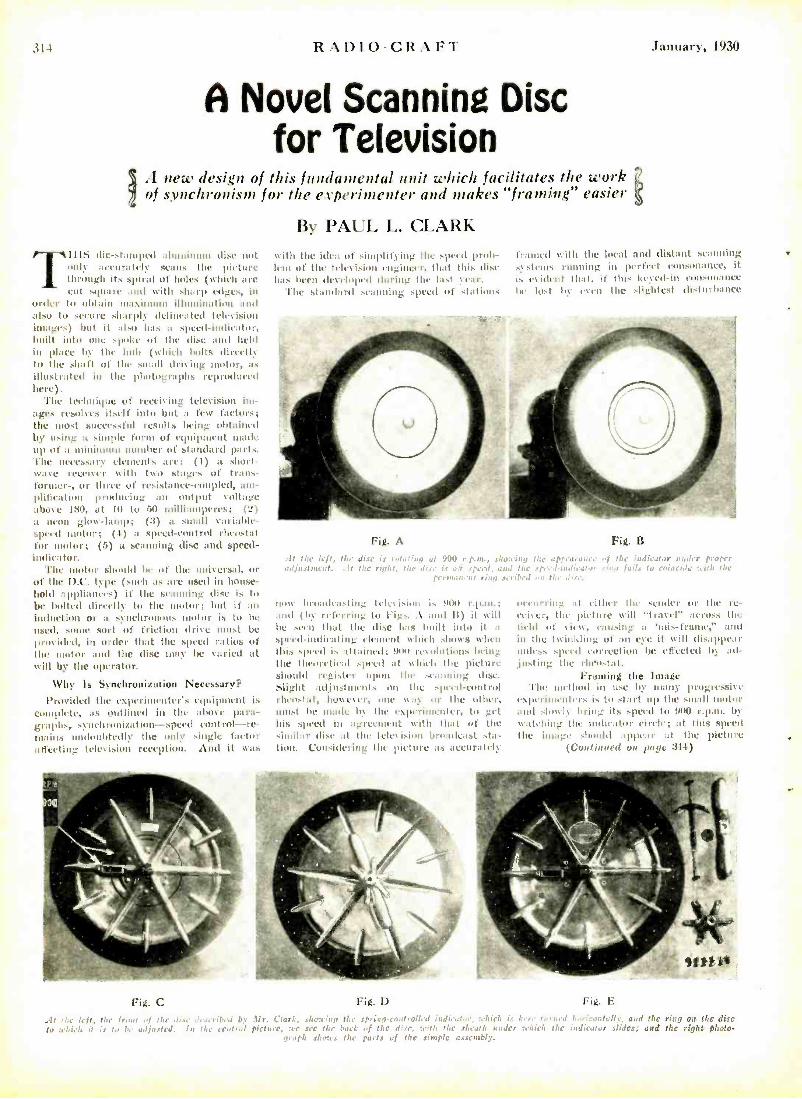
RAI)IU-CRAFT
A Novel Scanning Disc for Television
IA new design of this fundamental unit which facilitates the work of synchronism for the experimenter and makes "framing" easier
By PAUL L. CLARK TIIIS die -stamped aluminum dise not only arenrately scans the picture thnnigh its spiral of holes (which are cut square and with stoup edges, in
order to obtain maximum illumination and also to secure ,limply delineated television images) but it also has a speed -indicator. built into one spoke of the disc and held in place hV the huh (which bolts directly to the shaft of the small driving motor, as illustrated in the photographs reproduced) her).
'file technique of recciting television im- ages resulves itself into hilt a few factors; the most successful results bring obtained by using a simple form of equipment made up of a minimum number of standard pats. The necessary elements are: (I) a short- wave receiver with two stages of trans- former-, or three of rrsi.tanre- couplet), un- plitiratiom ptuduciug :ill nut put voltage above Itim, at II) to .r I milliamperes; (2) ;t neon glow -hump; (3) a small variable - speed motor; (4) a speed- control rheostat for motor; (5) a scanning disc and speed- indicator.
'l'he motor should be of the universal, or of the 1).C. type (such as are used in house- hold appliances) if the lemming disc k to be bolted directly to the motor: but it an
induction or a synchronous motor is to he
used, some sort of friction (Irk r must be
provided, in order that the speed ratios of the motor and the dise may be varied at will by the operator.
Why Is Synchronization Necessary?
l'Iovitled the experimenter's equipment is complete, as outlined in the above para- graphs, synchronization-speed control-re- mains undoubtedly the only single factor affecting teh\ision reception. And it was
with the idea of simplifying the speed prob- Ienl of the television engineer, that this dise has been developed during the East vain.
The standard scanning speed of stations
January, 1930
framed will) the local and distant scantling .Stems running in perfect consonance, it is evident that, if this keyed -ins consonance the lost I,y even the slightest disturbance
Fig. A
It the left, the .lis¡ ..ataina at 9 P r.p.rn., Shea': r r the a¡¡.araae, adjustment. .!1 the ri.,it. Npeof , a, i the ¡rI-;, 1,,,t,.,
ring .scribed , n n . se.
HOW hruadeastiig teletisio11 is 900 r.p.m.: and (l' re11rring to l'igs. A and 19 it will he seen that the disc has built into it a
speed- indicating clement which shows when this speed is attliled; !Ism re%olntiuus being the theoretical speed at which the picture should register upon the scanning disc. Slight adjustments on the speed-control rheostat, however, one way or the other, mntst he made h the experimenter, to get his speed in agreement with that of the similar disc at the television hen :edvast sta- tions. Cum side ring the piettua. ,ts .tt('Urltely
Fig. B
,f the indicator r,,dre inn teil., to coincide :c,th the
hecurriug it either the sender or the rc- eeiter, the picture will "travel across the field of view, e:mtsing a 'cis- frame;' :Hitt in the twinkling of an eye it will disap1li',r unless speed correction be effected h ad- justing the rheostat.
Framing the Image The method in use by many progressive
experimenters is to start up the ,mall motor and slowly bring its .speed to 9110 r.p.m. 1i watching the indicator circle: at this speed the image should appear at the picture
(Continued on pule :344)
Fig. C Fig. D Fig. E
AI the left, the front of the dire d,.erihed Gy :Ur. Clark, shadier the .pria.% n m trolled indicator, tclic1 is here t u rr, ed I..ria.:+talz. and the ring on the disc tu teliich it is to be adjusted. In the contra) picture, :cc see tho back of flic dire, with the sheath under :chie, the indicator slides; and the right photo-
i;rph .rh,res the pmts of the simple assembly.
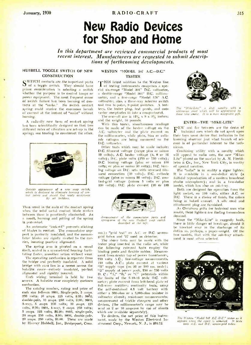
January, 1930 RADIO-CRAF"l
New Radio Devices for Shop and Home
315
In this department are reviewed commercial products of most recent interest. Manufacturers are requested to submit descrip-
tions of forthcoming developments.
HUBBELL TOGGLE SWITCH OF NEW CONSTRUCTION
SWITCH contacts are the important parts of a toggle switch. They should have
prime consideration in selecting a switch whether the purpose is to control lamps or power equipment. The most frequent cause of switch failure has been burning of con- tacts at the "make." No switch contact spring could receive the enormous inrush of current at the instant of "make" without burning.
A radically new forms of contact spring has been scientifically designed so that two different rates of vibration are set -up in the spring; one tending to counteract the other.
Outside appearance of a new snap switch, which is designed to eliminate burning of con- tact points and should find ready acceptance
by set builders.
'l'hus recoil in the ends of the contact spring when the solid metal contact blade strikes between them is practically el' ' ated. As a result, burning and pitting of the spring is prevented.
An automatic "kick-off" prevents sticking of blades in contact. The coin tator sup- port is perfectly insulated, and the coin mi- tator blades are rigidly riveted to the car- rier, insuring positive alignment.
The spring arm is pivoted on a round shaft. seated in a svmuuetrical bearing facili- tating faster, smoother action without wear.
The operating mechanism is separate from the bridge and perfectly insulated. A solid bridge with ears lies in a recess across the Bakelite cover- entirely insulated, perfect alignment and rigidity insured.
Each wiring terminal is held by two screws. A Bakelite case completely encloses mechanism.
The catalog number, rating and price of each size follows: 9801, Single -pole, 5 amps. 250 volts; 10 amps. 12.5 volts, $.55; 98112, double -pole, 10 amps. 250 volts, $.90; 9803, 3 -way, 5 amps. 250 volts; 10 amps. 125 volts, $.70; 9804, 4 -way, 2 amps. 250 volts; 5 amps. 125 volts, $2.20; 9805, single -pole, 20 amps. 250 volts, $.90; 9806, double-pole, 20 amps. 250 volts, $1.00. These are made by Harvey Hubbell, Inc., Bridgeport, Conn.
WESTON "MODEL 547 A.C. -D.C." TESTER
TITIS latest addition to the Weston line
of testing instruments comprises a spe- cial six -range "Model 301" D.C. voltmeter, a double -range "\laded 3111" D.C. millian- meter, and a five-range ".Iodcl 47(i' A.C. voltmeter; also, a three -way selectòr switch and two bi- polar, 9 -point switches. A bat- tery, the tester plug, test prods, and con- verter receptacles fit into a compartment.
The over -all size is 12aß, x 9 x 33 inches; and the weight, 10 pounds.
With this tester, simultaneous readings can be rade of the heater voltage on the A.C. voltmeter and the plate current on the milliaunmeter, while pole, bias or cath- ode voltages are being measured on the D.C. voltmeter.
Other tests which may be made include: D.C. filament voltage (range plus or minus 10 volts) ; A.C. heater voltage (4, 8 or 16 volts) ; D.C. plate volts (250 or 750 volts) ;
D.C. biasing voltage (plus or minus 100 volts; or plus or minus 50 volts) ; D.C. bias- ing voltage on D.C. sets with reversed fila- ment connection (50 volts); D.C. cathode voltage (plus or minus 50 volts) ; D.C. con- trol -grid voltage (minus 5 volts or plus 100 volts) ; D.C. plate current (20 or 100
Arrangement of the commutator parts and spring -arms of the new Hubbell snap switch
described at the deft.
nia.); "grid test" on A.C. or D.C. screen - grid tubes and '27 used as detector.
'l'he above tests may l . made with the tester plug inserted in the radio set, while the following external tests employ the binding posts and flexible cables: Measure- ment from center tap of power transformer, 750 volts A.C.; line -voltage measurements, 1.50 volts A.C.; plate current at various "It" supply taps (on 20 or 100 ma. scale); "11" supply at power pack, 2.50 or 750 volts 1). C.; "A," "13," or "C" potentials within the limits of the 5 -10-15 scale D.C. volt- meter; plate current from left -hand plate of full -wave rectifier; continuity tests, using the self- contained 4.5 volt battery with either a 500 -ohm or a 5,000 -ohm resistor in voltmeter circuit; resistance measurements: measurement of trickle chargers and other devices, (the rnilliamneter's range may be read as 2 or 10 amperes by use of shunts which are available separately).
To dealers, the net price of this instru- ment, made by the Reston Electrical In- strument Corp., Newark, N. J., is $93.75.
The "Mike- Lite," a desk novelty with a utilitarian slant which will be appreciated by those who smoke. ft is a moss acceptable gift.
ENTER -THE "MIKE -LITE" FEW and far between are the desks of
technical men which du riot sport upon their tops some device that indicates to the knowing observer just what branch of sci- ence is of particular interest to the tech- nician.
Combining utility with a novelty which will appeal to radio men, the new "Mike - Lite" placed on the market by A. M. Flecht- hciur & Co., Inc., New York Cite, is worthy of special mention.
The "mike" is in reality a cigar lighter. It is available in a one -dollar style (a faithful reproduction of a modern broadcast studio microphone) ; and in a two -dollar imodcl, which has also an ash -trap.
Both are designed for operation from the light socket, on 110 volts, either A.C. or D.C. There is a choice of finish, the colors being in baked enamel. .1 silk cord and attachment plug are furnished.
As Christmas gifts for technical men who smoke, these lighters are funding tremendous demand.
Since the "Mike -Lite" is ruggedly built, there is little clanger of breakage, should it be knocked over in the discharge of its duties as, perhaps, a paper- weight. Of the two models, that with the ash -tray attach- ment is most often selected.
The !feston "Model 547 .4.C. -D.C." tester as it appears tchen the rover is removed. It tests
both .I.C. and D.C. screen -grid tubes.
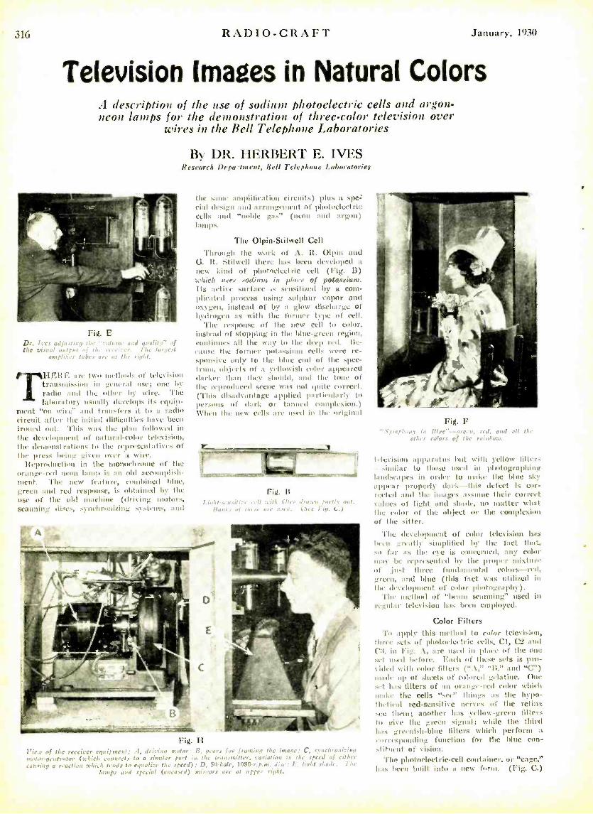
RADIO- CRA1'l' January, 1930
Television Images in Natural Colors A description of the use of sodium photoelectric cells and argon- neon lamps for the demonstration of three -color television over
wires in the Bell Telephone Laboratories
By DR. HERBERT E. IVES Research Depo -Intent, Bell Telephone Laboratories
rig_ r Dr. Ives ad¡r and quality" of tige Visual u The largest
amplifier tykes are at the right.
TH,HE a.... iwn ,.thuds of television transmission in general list; one by radin and the other by wire. The laboratory usually develops its equip-
ment "nn wire" and transfers it t.. is radio cirruit after the initial difficulties have been ironed out. This was the plan followed in the development of natural -eolor tel,cisiol, 1114. dranon.trations to lite representaliyrs of the press being given m er a wire.
Reproduction in the monochrome of the orange -red neon lamp is an old accomplish- ment. The new feature, combined blue, green and red response, is obtained by the use of the old unaehine (driving motors, scanning discs, synchronizing systems, and
the ,viii' auoplitication circuits) plus a spe= vial design and arrangement of photoelectric cells and "noble gas" (neon and argon) lamps.
The Olpin- Stilwell Cell
Through the work of A. R. Olpin and G. R. Stilvell there has lawn developed a
new kind of phohteleeirie cell (Fig. 13)
:which u,v, sodium is place of potassittro. Its aelitc wrface cnsilizcd by a com- plicated process using sulphur vapor and oxygen, instead of by a glow discharge of hydrogen as with the former type of cell.
The response of the new cell to color, instead of stopping in the blue -green region, continues all the way to the deep red. Be- cause the former potassium cells were re- sponsive only to the hhic end of the spec- trum, objects of a yellowish color appeared darker than they should, and the tone of the reproduced steer was not quite correct. ('Phis disadvantage applied parti,olarly to persons of dark or tanned eonnplrsion.) When the new [ells age 11stil in the original
isvus iti:, Hanks of an
:, ., Jrg:r+; uNv nul. are us.11. (Jee Iig, (:'.)
Fig. H l 'iea, of the receiver equ ilone al ; :I, Srith,., 11:4,1, or 13, nca rs for feu n, imp the in :roi : C, aye; hr.+uicinn m,C,
rieieratnr (which connects to a 51.1,11111r part i , (i.e transmitter, variation iii the speed of either
as u.i!a a reaction cchieh tends to equalise the speed); D. 50 -hole, 10$0 -r. p. nn. dise; F., fight .1. aile, The 1,nnps all special (eu eased) ,Grors are at tpt'r , iaht.
Fig. F Sy mkt: .... in Uhr. -- a re: n, ed. and all Noe
oilier colors of ti:.' ,e'nno,,:e.
television apparatus hot with yellow litter: -- similar to those used in photographing landscapes in order to make the blue shy appear properly dark--this defect is cor- rected and the images as.mae their correct volncs of light and shade, no matter wheat
the ,Ior of the objt',t or the complexion of the sitter.
'l'ht development of color television has been greatly simplified by the fact tlntt, so far as the r is eoueerncd, any color may be rep rtsented by the proper mixture of .just three fundamental colors -red, greet, and blue (this fact was utilized in the development of color photography).
The method of "Ilea In scanning" used in regular television has heel' employed.
Color Filters 'l',t apply this method to enloe television,
1óree sets of photoelectric cells, CI, C3 and (':1, in Fig. .1, are used in place of the one set used before. 1:ae'h of thew sets is pro- vided with color tillers ('. \;' 'I1;' and "C ") made up of sheets of colored gelatine. One set has filters of an orange -rod odor which n a:a l.t the cells "see" things as the hypo - thetical red -sensitive nerves of the retina set' Hain; another has yellow -green filters to give the green sigmd; w'hilc the third has greenish-blue filters which perform a corresponding function for the bitte con- stituent of vision.
The photoelectric -cell container, or "cage," has been built into a new forth. (Fig. C.)
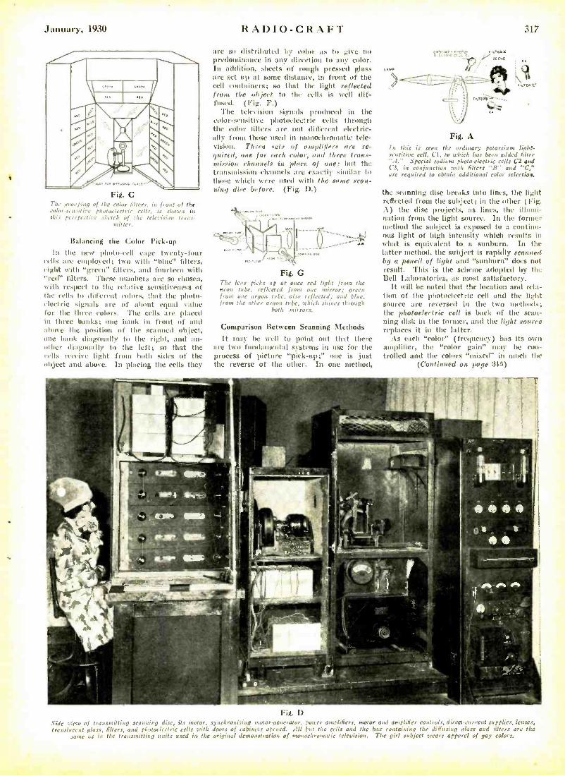
January, 1930
Fig. C The ,,nu ping of the color filters, ht fron of Ihn color- sensit he photoelectric cells, is shaten in this perspective .drisch of the television irons-
Balancing the Color Pick -up
In the new photo -cell cage twenty -four cells are eu gployed; two with "blue" filters, eight with "green" filters, and fourteen with "red" filters. These numbers are so chosen, with respect to the relative sensitiveness of the cells Io different colors, that the photo - cicctic signals are of al rout equal value for the three colors. The cells are placed in three banks; one bank in front of and above the position of the scanned object, one bank diagonally to the right, and an- other diagonally to the left; so that the cells receive light from both silks of the object and above. In placing the cells they
RADIO-CRAFT 317
are so distributed by color as to give no predominance in any direction to any color. In addition, sheets of rough pressed glass are set up at some distance, in front of the cell containers; so that the light reflected froeee the object to the cells is well dif- fused. (Fig. F.)
The television signals produced in the color -sensitive photoelectric cells through the color liitl'rs are not different electric- ally from those used in monochromatic tele- vision. Three sels of amplifiers are re- gHireel, one for each color, erred three trans - mission channels in place of one: but the transmission channels are exactly similar to those which were used with the same scan- ning disc before. (Fig. I).)
,. ...\\c
Fig. G The leas picks up et once red light front the neon tube, reflected from one mirror; green from use argon tube, also reflected; and blue, from the of argon tube, which shines through
both mirrors.
Comparison Between Scanning Methods
It may he well to point out that there are two fundamental systems in use for the process of picture "pick-up;" one is just the reverse of the other. In one method,
LAMO
oc, :.r. fra 't <.
Fig. A In this is seen the ordinary potassium linbt- sensitive cell, Cl, to which has been added filter ".1." Special sodium photo -electric cells C2 and C'3, in conjunction teill, filters "H" and "Car arc required to obtain additional color selection.
the scanning disc breaks into lines, the light reflected from the subject; in the other (Fig. A) the disc projects, as lines, the illumi- nation from the light source. In the former method the subject is exposed to a continu- ous light of high intensity which results in what is equivalent to a sunburn. In the latter method, the subject is rapidly scanned by a pencil of light and "sunburn" does not result. This is the schiente adopted by the Bell Laboratories, as most satisfactory.
It will be noted that the location and rela- tion of the photoelectric cell and the light source are reversed in the two methods; the photoelectric cell is back of the scan- ning disk in the former, and the light source replaces it in the latter.
As each "color" (frequency) has its own amplifier, the "color gain" may he con- trolled and the colors "mixed" in notch the
(Continued on petite 315)
Fig. D Side view of transmitting scanning disc, its motor, synchronizing motor -generator, power amplifiers, motor and amplifier co,trole, direct -current supplies, lenses, translucent glass, filters, asid photoelectric cells with doors of cabinets opined. .Ill but the cells and the box containing the diffusing glass and titters arc the
sane as in the transmitting wilts used in the original demonstration of monochromatic television. The girl subject wears apparel of gay colors.
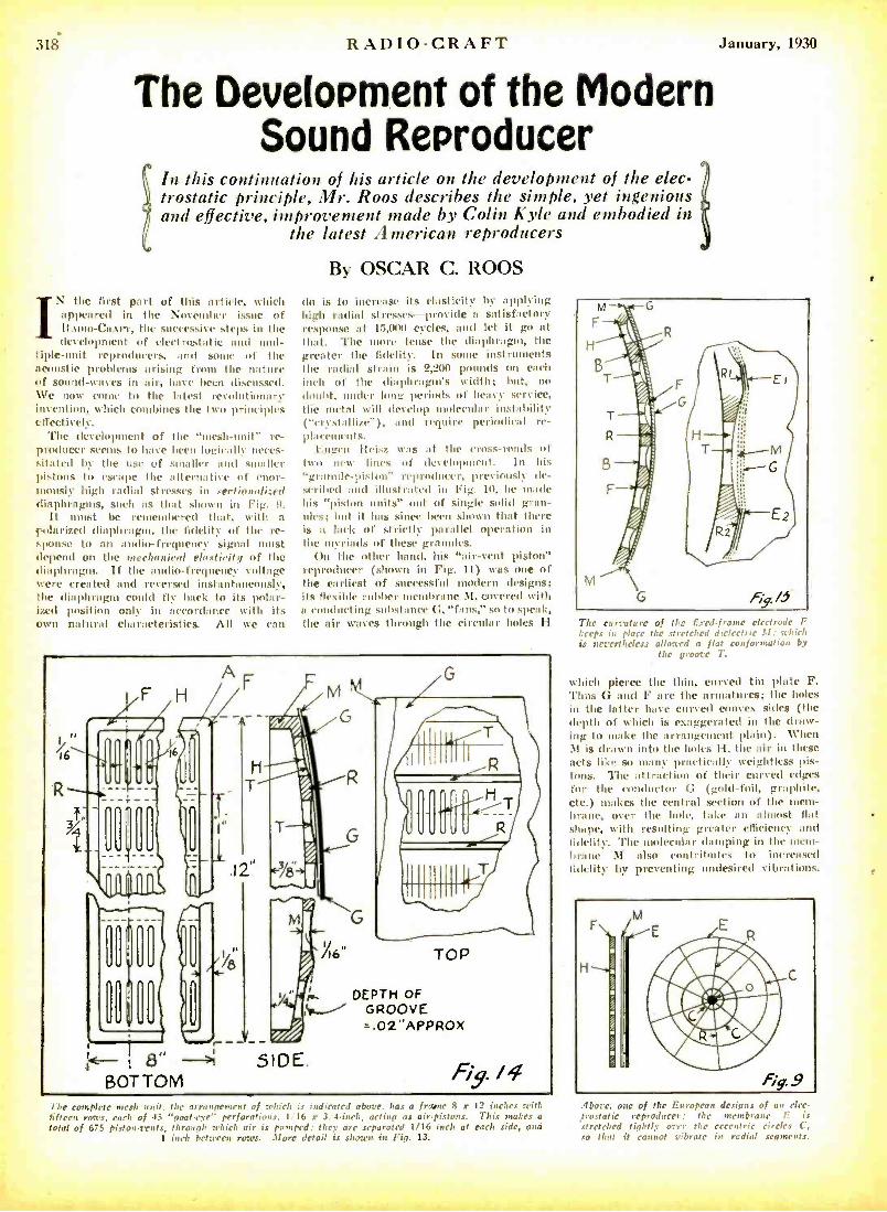
318 RADIO -CRAFT
The Development of the Modern Sound Reproducer
In this continuation of his article on the development of the elec- trostatic principle, f1lr. Roos describes the simple, yet ingenious and effective, improvement made by Colin Kyle and embodied in
the latest American reproducers
IN the first part of this article, which appeared in the November issue of Itnuto- Ca.trr, the successive steps in the development of electrostatic and nuul-
iple -unit reproducers, and some of the tcoustic problems arising from the nature )f sound -waves in air, have been discussed. 1Ve now come to the latest revolutionary nvention, which combines the two principles ffectively. 'l'he development of the "mesh -unit" re-
producer seems to have been logically neces- .ita ted by the use of smaller and smaller pistons to escape the alternative of (nor- inously high radial stresses in sectionalized diaphragms, such as that shown in Fig. 9.
It must be remembered that, with a solarized diaphragm, the fidelity of the re- ponse to an audio -frequency signal must
depend on the mechanical elastirilry of the liaphragm. If the audio -frequenc voltage were created and reversed instantaneously, the diaphragm could fly hack to its polar- ized positimn only in accordance with its own natural characteristics. All we can
By OSCAR C. ROOS
do is to increase its elasticity by applying high radial stresses -provide a satisfactory response at 15,000 cycles, and let it go at that. 'l'he more tense the diaphragm, the greater the fidelity. In some instruments the radial strain is 2,200 pounds on each inch of the diaphragms width; but, no doubt, under long periods of heavy service, the metal will develop molecular instability ('crystallize "), and require periodical re- placements.
1 :ugen Ileisz was at the cross -roads of two new lines of development. In his "granule- piston" reproducer, previously de- scribed and illustrated in Fig. 10, he made his "piston units" out of single solid gran- ules; but it has since been shown that then is a lack of strictly parallel operation in
the myriads of these granules. On the other hand, his "air -vent piston"
reproducer (shown in Fig. 11) was one of the earliest of successful modern designs; its flexible rubber membrane M, covered with a conducting substance G, "fans." so to speak, the air waves through the circular holes II
I
January, 1930
The curvature of the fixed.frame electrode F keeps in place the stretched dielectric .11: which is nevertheless allowed a flat conformation by
the groove T.
which pierce the thin, curved tin plate F. Thus G and F are the armatures; the holes in the latter have curved convex sides (the depth of which is exaggerated in the draw- ing to make the arrangement plain). When . 1 is drawn into the holes II, the air in these acts like so many practically weightless pis- tons. 'l'he attraction of their curved edges fur the conductor G (gold -foil, graphite, etc.) makes the central section of the mem- brane, over the hole, take an almost flat shape, with resulting greater efficiency and fidelity. The molecular damping in the mtem- In':ne \I also contributes to increased fidelity by preventing undesired vibrations.
he complete rn rsh unit, the a , of which is indicated above. ha, , 'nil,:. ` .r 12 inches with fifteen roars, each of 45 "coat eve' perforations. 1,16 s 3'4.iueh, actin., as air.pistons. This makes a total of 675 pisto .vents, through which air is pumped; they are separated 1/16 nch at cad: side, and
1 inch between rows. More detail is sho-'n in Fig. 13.
.I1',ß; c. one of the European designs of an elee- tro,:tatic reproducer: the membrane E is
'stretched tightly over the eccentric circles C, so that it cannot vibrate in radial segments.
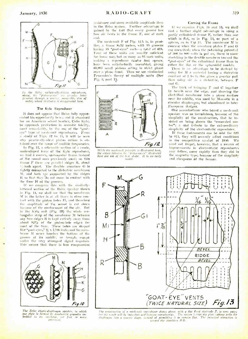
January, 1930
lac the Reis_ unilaterally- driven reproducer, above, the "piston.t'e;I1.:' circular tholes punched fu rough a Convex. 'saunrlike disc of
metal, whose thickness is exaggerated lure.
The Kyle Reproducer
It does not appear that lüisz fully appre- ciated his opportunity here; and it remained Mr an American school teacher, Colin hyI, to approach perfection in acoustic fidelity, most rents rkahly, by the use "t' the "goat - eye" type of mush -unit reproducers. from a study Of Figs. 12 to 15, it will he .cell 1111\ practically -ideal piston action is ob- tained over the range of audible frequencies.
lu trig. I. a schematic seelion of a crude, inilevclopcd form of the F Iw reproducer, wit lind a convex, reel.'oggl'r fruit(' intend of the round ones previously used; on this frame F there are parallel ridges R, about tu, -inch apart. '1'hc flexil,l, armature G is tightly Connected to the dielectric membrane M. and both are supported by the ridges It so that they do not come in contact with the floor II of the grooves.
If we compare this with the similarly- lettered section of the lteisr speaker shown in Trig. ll, we shall see that the membrane \I in the Taller is at all tunes in clove eon- Met with the piston holes 11, mud theret.ne the amplitude of the sound is eut down because of the confinement of the air. nut in the 1:yle unit (Fig. 12) the whole rec- tangular strip of the membrane M between any two ridges It is kept entirely away front about 92% of the piston -hole edges for most of the time. These holes are shaped like "goat- eyes," 3,4 x 1/111 -inch; and the mem- brane M never touehrs the bottom of the groove at its uniddle. or trough, except under the very strongest signal impulses. This means that there is less eoutpres.ion
fig. /O
The Reis: clastic -diaphragm speaker, in t,Li,l, one plate is formed by conductive gra nalea i,. bedded in an .u.ry l,aor, art free fo n: -v
other., r.
1tA1)1U-C1t:1FT 319
resist:ntc and nnne :1V:tilnhlc +uuplilude nigh in It, Meus4 s1 t,ut. Further advantage is gained by the fact that every groove has two air cents in the frame Ir, one at each end.
The mesh -unit F of Fig. 12.\ is, in pt:ne- Iiee. a frame 8\12 inches, with lb grooves hat Mg. 45 "goat -rye:' each -at total of 675. I'onr of these units are usually sufficient for home use; but as many as 95 such units, mahin_ n reproducer twelve feet square, have hewn satisfactorily assembled, giving 134,800 small pi.tnns acting in strict phase over a plane front. Thus We see eindiatted Fessendeti s theory of multiple nuits (Sec Fig. 3, part I).
While the ntc.duuit p... r r a i!'> st rot rd lucre, the ridges bet:teen the "fist.- :h-Tags' i1 /u st rated lucre arc not of the hest .shape. It is as early
mod,d.
Curving the Frame If we ea:nninr figs. 1-l. and 15, we shall
find a. further slight advantage in using a.
partly cylindrical frame F, rather than one which is flat, as in Fig. 13, or part of a sphere, as in Fig 11. 'l'he membrane \I is concave when the armature plates F anal G are unexcited; when the polarizing potential of :ino to SINI volts is put on, there is more sl retching in the flexible members toward the "goat -eyes" of the cylindrical frame than in either the flat or the spheroidal models.
There is an advantage to be derived by using for : t a material having a dielectric eoustant of _ to :i; this gives a greater pull than using air as a dielectric. between F and G.
'flue trick of bringing I" and G together by bevels near the edge, and drawing the electrified membrane into a plane surface near its middle, was used by \Iassolle in a circular tliaplirutpit; but abandoned in lutter F.urnpcan designs.
One manufacturer who heard a mash -unit speaker was so incredulous, because of the simplicity of the construction, that he in- sisted on being shown the "concealed mo- tor"; n real tribute to the extraordinary simplicity of the electrostatic reproducer.
If these instruments can be sold for $20 to $75, they will severely affect conditions in the competitive market of 1930. We must not forget, however, that a swarth of improvements in eleetrostatic reproducers may follow, more rapidly than they did in the magnetic type, because of the simplicity and cheapness of the former.
7/ g
RIDGE
°GOAT- EYE" VENTS (TWICE NATURAL S /ZE) Fi /3
The cnn.,t nn!L.0 of a meslo-: v it repr0d :1\r sh,rrn aime. veut: a flot t7.1-.-,1 cje,vr,rie F, is very easy;' btuf the result sill be imperfect and h: :ants reproduction. The reason is that the plate voltage pulls the diaphragm into a eanvr.r shape. instead of permitting it to remain flat. The principal attraction is
tocard the shoulders li-B.
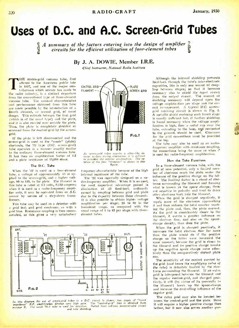
RADIO -CRAFT January, 1930
Uses of D.C. and A.C. Screen -Grid Tubes A summary of the factors entering into the design of amplifier
circuits for the efficient utilization of four- element tubes
By J. A. DOWIE, Member I.R.E. Chief Instructor, National Radio Institute
THE screen -grid vacuum tube, first offered to the American public late in 1927, and one of the major con- tributions which science has made to
the radio industry, is a distinct departure from the conventional type of three- element vacuums tube. The unusual characteristics and performance obtained from this tube are made possible by the introduction of a
fourth element, or second grid, of novel design. This extends between the first grid (which is of the usual type) and the plate, and it ix also carried over outside the plate. Thus, the plate is completely shielded or screened from the control -grid by the screen - grid.
If the plate is left disconnected and the screen -grid is used as the "anode" (plate) electrode, the '22 type (D.C. screen -grid) tube operates in a manner exactly similar to the ordinary three- element vacuum tube. It has then an amplification factor of 6.5
and a plate resistance of 15,000 ohms.
The D.C. Tube When the '22 is used as a four -element
tube, a voltage of approximately 45 is ap- plied to the screen -grid, and a higher volt- age, 90 to 135, to the plate. The filament in this tube is rated at 3.3 volts, 0.132- ampere; when it is used as a radio-frequency ampli- fier only, it may be operated from an A.C. source by means of a step -down trans- former.
This tube mm- be used as a detector with a grid leak and grid condenser, or with a grid bias. Resistance coupling is then recom- mended, as this gives a very satisfactory
CONTROL GRID^
FILAMENT -- PLATE
SCREEN GRID
As screnrgrid tubes acquire a silver -like in- terior surface during evacuation, it is difficult to visuah'ae the interior construction. The re- lation of the four "elements" is shown in this
figure.
frequency -characteristic because of the high internal resistance of the tube.
'l'he '22 was especially designed as a ra- dio-frequency amplifier. When it is so used, the most important advantage gained is
elimination of all feed -back ordinarily caused by coupling between grid and plate due to the capacity between these elements. It is also possible to obtain higher voltage amplification per stage; 20 to 50 in the broadcast range, as compared with the usual range of 5 to 12 per stage with three - element tubes.
In this diagram the use of screen -grid tubes in a D.C. circuit is shown; two stages of "tuned
impedance" R.F. amplification develop very high gain. The "control- grid" bias is obtained from
resistor R. The usual '01. -1 tube is used for detection. Dotted lines indicate recommended circuit and tube shielding.
Although the internal shielding prevents feed -back through the tube's inter- electrode capacities, this is only one source of coup- ling between stages; so that it becomes necessary also to shield the input circuit from the output circuit. 'l'he amount of shielding necessary will depend upon the voltage amplification per stage and the cir- cuit arrangement. A typical D.C. screen - grid receiving circuit is shown in Fig. 2.
A metallic shield enclosing each tuned stage is usually sufficient lait, if further shielding is found necessary when the voltage ampli- fication is high, then a metal cap over the tube, extending to the base, and connected to the ground, should be used. Clearance for the grid connections must be provided at the top.
'l'he tube may also be used as an audio- frequency amplifier with resistance coupling, the connections being the same as when i` is used for radio -frequency amplification.
How the Tube Functions
In a three -element vacuum tube, with the grid at zero potential, only a lia iZed num- ber of electrons reach the plate under the influence of the positive charge on the lat- ter. The limiting factor is a cloud of elec- trons surrounding the filament and forming what is known as the spare charge; these are negative in polarity and tend to drive other electrons back into the filament.
When the grid is charged negatively, it repels some of the electrons approaching it and thus reduces the total number reach- ing the plate and, thus, the plate current. As the grid is considerably closer to the filament, it exerts n greater influence on the electron flow, and also on the space - charge density, than does the plate.
When the grid is charged positively, it increases the total electron flow far more than the plate would do if the positive charge on the latter were increased the same amount; because the grid is closer to the filament and its positive charge breaks up the negative space charge more effec- tively than the comparatively distant plate can.
The sensitivity of the control exerted by the grid (and hence the amplifying value of the tube) is definitely limited by the d ec- trons surrounding the filament. If an extra grid is interposed between the filament and the regular control -grid, and charged posi- tively, it will (liv virtue of its proximity to the filament) break up the space- charge and increase the controlling influence of the regular grid.
The extra grid may also be located be- tween the control -grid and the plate. Here it will require a higher positive charge than before, but it now also serves another pur-
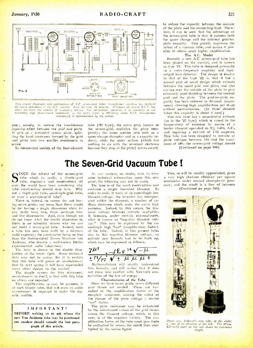
January, 1930 RADIO-CRAFT 321
AO 0
FEG.3
t IDO
llfYLal MEPTECc`-TE é`- (IM«aOE F.
(PTHOUE
SCPftuPp xnCm .tTEP !OTTO,. at BeSE (or.E[ 0N5
This circuit illustrates two applications of .4.C. screen-grid tubes: transformer nplig has replaced the tuned impedance hi the K.F. coupler. Note the type '24 detector, (Primary of second K.F.T. has about ogle -iI,ird the number of secondary turns.) For satisfactory operation it is necessary to use extremely high platy -eireu it impedance: in the audio input. a 500 -henry choke (.1,F, transformer
secondary) is recommended by the author.
pose; acnnelg, to reduce the troublesome capacity effect between the grid and plate. It acts as a grounded center plate, split- ting the fixed condenser formed by the grid and plate into two smaller condensers in series.
In commercial models of the four -element
tube ('22 type), the extra grid, known as the screen- grid, encircles the plate com- pletely; the inner section acts both as a
space -charge disrupter and as a capacity re- ducer, while the otter section (which has nothing to do with the screened electrons because they stop at the plate) serves merely
to reduce the capacity between the outside of the plate and the connecting lead. There- fore, it can be seen that the advantage of the screen -grid tube is that it reduces troth the space charge and the internal grid -to- plate capacity. 'Phis greatly improves the action of a vacuum tube, and uutkes it pos- sible to obtain much higher amplification.
The A.C. Model Rccenth a new A.C. screen -grid tube has
been placed on the market, and is known as type '24. This tube is designed primarily as a radio-frequency amplifier and high- output bias detector. The design is similar to that of the type '22, in that it has a second grid of novel design which extends between the usual grid and plate, and also carries over the outside of the plate to give extremely good shielding between the control grid and the plate 'l'he grid -to -plate ca- pacity has been reduced to .01 -nuuf. (maxi- mum) allowing high amplification per stage without neutralization. (In three element tubes this capacity is about 9 uunf.)
This new tube has a unipotential cathode (as in the '27 type) which is raised to the temperature of emission by means of a
heater filament operated on 21¡- volts, A.C., and requiring a current of 1.75 amperes. This tube has been designed to operate at plate voltages between 135 and the maxi- mum of 180; the screen -grid voltage should
(Continued on page 346)
The Seven -Grid Vacuum Tube !
S INCE the advent of the screen -grid Suite which is, really, a double -grid toot', engineers and constructors all
over the world have been wondering why tube constructing should stop Isere. Why not a triple -grid tube, quadruple -grid tube, or even a septuple -grid tithe?
There is, indeed, no reason for not hav- ing seven grids; any more than there would be for having a single dimension when we can really have two, three-perhaps four and five dimensions. And, even though we do not know what the fourth dimension is, there is no scientific reason why we can not build a seven -grid tube. Indeed, such n tube has now been I nilt by a German radio engineer; the constructor being no less titan the distinguished Baron Manfred von Ardenne, who directs a well -known Berlin exper' intal radio laboratory.
The tube is shown in the double illus- tration at the lower right. Some technical data may not be i. uiss; for it is certain that this tube will prove so revalut my that by next spring it will have superseded every other design on the market.
'l'he simple reason for this statement, revolutionary in itself. is that with this tube no a/hers are required.
The amplification, as may be guessed, is of such titanic ratio, that not even an audio transformer is required to make the sig- nals audible.
IMPORTANT! BEFORE writing us to ask where the new Von Ardenne tube may be purchased, our readers should consult the last para-
graph of this article.
. \, our renders, no doubt, wish to have some technical information upon this new giant, the following may not be amiss.
The tube is of the usual construction and contains a single thoritited filament. In order to snake it work at an exceedingly low filament- voltage, the inventor has incorpor- ated within the filament, a number of ra- dium electrons which make for extra high emission. Indeed, by this means, the fila- ment voltage becomes entirely negligible; it becomes, under certain circumstances, what is known its "negative filament volt- age." This may be explained by the ex- e((dingly high "ntu" ( amplification factor) of the tube. Indeed, in this present tube, due to this negative filament voltage, an entirely new formula had to be built up, [which may be expressed as follows:
Y7 7 -d'E 9. 14 .-µ
± 7'1/7'7 1 ± µ /u µ 6 Ma thema ticia ns trill readily understand
this formula. and will realize that it does not come into conflict with Newton's con- servation of the law of energy.
Characteristics of the Tube Since we have seven grids, seven different
grid biases are needed. These are fur- nished by the imiplificati,to factor of the complete resistance, making the ratios of the change of the plate voltage a double "nor" factor.
The plate resistance may he calculated by the ascertained values of the grid biases minus the filament voltage, which, in this case, is of the negative variety. The am- plification factor of the tube t ipso facto be Itiplied by seven; the result then mul- tiplied by tin' minus figure.
Phis, as will be readily appreciated, gives a very high electron efficiency per square centimeter tinder normal atmospheric pres- sure; and the result is a flow of between
(Continued on page 346)
Horan von .4rdeo,r'.s new tube, at the right; a tiro, of its elements at the left. The 50 -cm. (20 -inch) mark ou the rule shores its enormous
length.
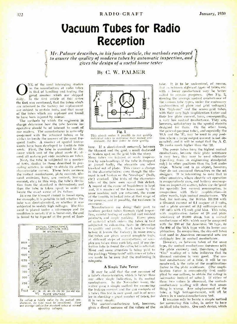
311 RADIO -CRAFT January, 1930
Vacuum Tubes for Radio Reception
Mr. Palmer describes, in his fourth article, the methods employed to assure the quality of modern tubes by automatic inspection, and
gives the design of a useful home tester
0 \L' of the most interesting studies in the manufacture of radio tubes is that of handling and testing the great number which are shipped
daily. ln the first article of this series the fact was mentioned, that the tubes which are returned to the factory for replacement are subject to certain tests, and that many of the tubes which are replaced are found to have been injured by misuse.
The methods by which the engineers in charge determine how the tube became in- operative should he of interest to most of our readers. The manufacturer is naturally concerned with the returned tubes; as he wishes to locate the sources of the most fre- quent faults. A number of special instru- ments have been developed to facilitate this work. First, the tube is examined to dis- cover which unit of the plant made it al- most all makers put code numbers on tubes.
Next, the tube is stili,jtuted to a number of tests, similar to those described in pre- ceding :alleles, in order to obtain its actual characteristic curves. These tests measure the mutual ii tducttuncc, plate current, fila- ment cuuiSsiUn, hum, gas content, leakage current, etc.; in this way, the tube's devia- tion from the standard is determined; and then the tube is token apart in order to locate the exact couse of its failure.
In case the filament circuit is found open, for example, it is possible to tell whether the tube was short -circuited, or whether il was subjected to unduly high voltages. The fila- ment is plowed under a microscope tutti its condition is noted; if it is burnt -out, the end is found to he to pored at the point of frac-
MUTUAL CONDUCTANCE or PECEIV NG TUBE TYPES
IN MICIIOMHOS
In rating a tube's value by its mutual con- ductance, its type raust be considered. Leere are average values for standard tubes at tormal
operating voltages.
By C. W. PALn1LR
Pig. 1
This circuit n:.: ,ible to test quickly Individual ¡abus r:Lnc their mutual coi -
ductatiee, the ben index to their quality.
turc. If a short -circuit occurred, between the filament and the grid, a small darkened or broken spat un the grid tells the story. Maury tubes :ne injured or tonde inopera- tive by mis- handling; if the tube is dropped or ,jarred badly. the elements :ne often knocked out of place. This causes a uiu utgc in the characteristics; oven though the fila- fluent is not broken or the "envelope" (bulb, ete.) (railed. 'flue tests of the character- istics of the tube soon reveal this defect. A record of the cause of breakdown is kept anti, if :I number of the tubes made by the same tu:chine unit :ne returned, the cause of the trouble is looked into at that stage of the process; and if passible, the weakness is Uyw rim n(.
Manufacturers :ne doing their part to produce perfect tubes through rigid inspec- tion, careful listing cif m :terial and finished products, and ample pocking. ]:very piece of material which enters the tubes is first subjected tu exhaustive tests to determine ils quality and purity. Each tube is tested before it leaves the factory; in soute cases, the tubes are given several complete tests, nt different steps of manufacture, or sam- ples are taken front each lot; and if une de- fective tube is found the entire lot is retested. More :nad more attention is being paid to the packing; "drop tests" with cases of tubes are made to be sure that the cushioning is adequate.
A Simple Tube Tester
It may be said that the one measure of a tube's characteristics, widrh i; better than any other single indication, is ils mutual cuuduclance. In the Nuteuibrr issue, the writer guise a simple method for measuring the leakage current and the gas contents of a tube; this test is verre good und is of serv- ice in checking a great number of tubes, for it is very simple.
The meulant- ronduetonee test, however, gives a direct measure of the values of the
tube. It is to he understood, of course, that as between deferent types of tubes, one with a lower conductance may be better suited to certain purposes. (See Fig. 2, showing the average mutual conductance of the c :tiiuus tube types, tattler the customary combinations of ',lade and grid voltages.) The "high -nit' and the screen -grid tubes, with their very high amplification factor and their low plate current, have, consequently, a very low mutual conductance. They are, however, sati.sfactury in the special circuits designed for them. (hi the tidier hand, the general -purpose tubes, and especially the '01A and the '27, may be used in any posi- tion where a large output current is not de- manded; and it will be noted that the A. C. '24 ranks much higher than the '22.
The power tubes have the highest mutual conductance, because their plate resistance is very low; they may he used efficiently (speaking from an engineering standpoint only) in other positions than the last audio stage. Where cost is an object, however, they do not commend themselves to the set designer. It is interesting to note that in other countries, wherc electric set operation is pa raticil- rate, and battery ectnsuntp- tiun an important matter, tubes are de: hgned for speci:illy line current consninpthuu, in comparison with their amplification -in other words, high mutual conductance. R'e find, for instance, the British 111 .210 with a filament current of 0.1 ampere at 2 colts, and a plate current of 3.2 milliamperes at 110 volts with 115 -volt grid bias. This tube, with :uuplitieution factor of 20 and plate resistance of 23,000 ohms, has a mutual conductance of 870; which may be compared with the 200 of the American '40 type, or the S00 of the 'OlA type with its lower am- plification. In comparison, the dry -cell tubes first used in American commercial sets are strikingly low in mutual conductance.
IIowevcr, as between tubes of the saute type, the mutual conductance increases with lute plate current; and, therefore, a high "Gm" reading of a tube indicates that its filament emission is very good. The mu- tual conductance of a tube, it will be re- membered, is the ratio of the amplification- factor to the plate resistance. ('l'hc ampli- fication fact or is conveniently first multi- plied by ono million, to obtain the rating in lair oroubus instead of mhos.) If either of these two values is al rural, the tual- eondncttuuc reacting will show that some- thing is wrong. .,1ny misplacement of the tube, a high leakage -current, will all be shown ht a mutual- conductance test.
It remains only to locate a simple method for measuring this value, in order to have an ideal tube tester. One such device, which
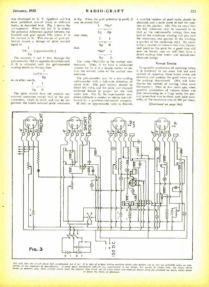
January, 1930
was developed by E. V. Appleton and has been published several times in different books, is described here. Fig. 1 shoes the arrangement. When the key K is closed, the potential difference applied between the filament and grid equals l'IR, where 1' is the current in lt. This change of grid po- tential causes a change of plate current equal to
I l'R- (approximately.) Eg
The currents I and I' flow through the galvanometer MA in opposite directions and, if It is adjusted until the galvanometer reading shows no change, then
I I =I'R-
Eg or, in other words,
I I
Eg The plate circuit does not contain any
external resistance except that of the gal- vanometer, which is small and can be ne- glected; the tube's internal plate resistance
RADIO-CRAFT 323
is Rp. When the grid potential is small, it may be stated that
I "Mu"
Eg Rp and, since,
then "Mu" 1
Itp R The value "Mai' /Itp is the mutual con-
ductance. Then, if we have a calibrated resistor for H, it is a simple matter to ob- tain the correct value of the mutual con- ductance.
The galvanometer may he a low -reading millia mmeter with a full -scale deflection of about 0 -10. The grid battery should be a a bout 41 volts, and the plate aml filament batteries should be proper for the tube under test. For R, the experimenter may either calibrate a resistor or obtain one cali- brated by a precision -instrument company.
If only an approximate value is desired,
a variable resistor of good make should be obtained, and a scale made to suit the posi- tion of the pointer. (By this we mean that the full resistance may be assumed to be that of the instrument's rating; then one half of the resistance winding will give half the resistance; one quarter of the winding, a quarter of the resistance, etc.) 11y meas- uring a number of tubes in this way, thecor- rect point on the scale for a good tube will soon be found; and we will then have a direct- reading tube tester and mutual -con- ductance bridge.
Manual Testing
In quantity production of receiving tubes, it is necessary to use some fast but sure method of rejecting those tubes which are defective and passing the good tubes on to the packing department. (We will later discuss the method of making tubes more thoroughly.) Four or five years ago, when quantity production of vacuum tubes was just commencing on a large scale, the gen- eral procedure was to check each tube man- ually, at the maximum rate of 225 per hour,
(Continued on page 346)
Not only dors the circuit above look complicated, but it is, It is that of a large testing machine which tube makers use to sort out defective. tubes on com- pletion of the processes of manufacture. A great many mechanical features arc incorporated in the design, but cannot be shown here; the relays (here shown as meters) close other circuits which work the ejectors that throw out all tubes whose test readings depart from the standard too much, either above or below the limits of tolerance.
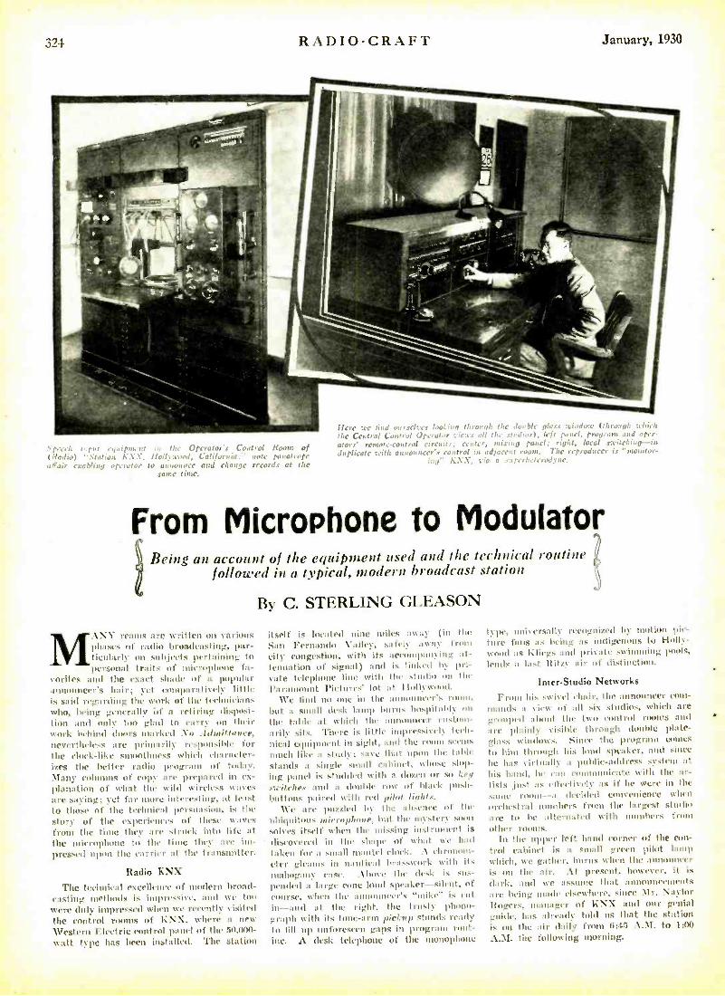
RADIO -CRAFT January, 1930
a t o p y ootrot Room of (Radio) -Station K X. i. Calif ..ru :a;' note po oatrope a6air enab ling operator t, c and change records at the
same time.
Here we find ourselves looting to rouoh the Jonh!r ola.cs ,eiIJ.W (through which the Central Cunt nd Operator views rs all tlrc studios), left panel, prnararn and oper-
ators' remote-control circuits: center, pane!; right, local switching-in. duplicate with announcer's control in adjanut room. The reproducer is "monitor-
ing" KXX, pia a e: perlrtermlwtr.
From Microphone to Modulator Being an account of the equipment used and the technical routine
followed in a typical, modern broadcast station
By C. STERLING GLEASON
MANY reams are written on various phases of radio broadcasting, par- ticularly on subjects pertaining to personal traits of microphone fa-
vorites and the exact shade of a popular announcer's hair; it eon(parativdy little is said regarding the work of the technicians who, being generally id a retiring disposi- tion and only too glad to carry on their work behind doors marked No .Idmillnace, nevertheless are primarily responsible for the clock-like smoothness which character- izes the better radio program of today. Many columns of copy are prepared in ex- planation of what the wild wireless waves are saving; yet far niore interesting. at least to those of the technical persuasion, is the story of the experiences of these waves from the time they are struck into lite at the microphone to the time they arc im- pressed upon the carrier at the transmitter.
Radio KNX
The technical excellence of modern broad- casting methods is impressive, and we too were duly impressed when we recently I kited the conirol rooms of XXX, where a new Western Electric control panel of the 50,000 - watt type has been installed. The station
itself is located nine miles away (in the Son Fernando Valley. safely away drone
city congestion, kith its accougnnning at- tenuation of signal) and is linker) by pri- vate telephone line Icitlt the studio on the Paramount Picture: lot at Ilnlllwood.
We lind no one in the announcer's room, but a small desk lamp burns ho.pitablc on
the table at which the announcer euslonr- :rrily sits. There is little impressively tech- nical equipment in sight. and the room seems
much like :r study: save that upon the table stands a single small cabinet, whose slop- ing panel is studded with a dozen or so keel
switches and a (limbic row of block push- buttons paired with red pilot lights.
\Ce are puzzled by the absence of the ubiquitous microphone, bat the mystery soon sub es itself when the missing instrument is
discovered in the shape of what we hall taken for a small (uautel clock. .1 chronom- eter gleams in nautienl brnsswork with its nudmgauy ease. .lboye the desk is sus- pended a large cone loud speaker -silent, of course, when the announcer's "mike' is cut in-and at the right, the trusty phono- graph with its tone -arm pickup stands ready to till up nnforesren gaps in program rout- ine. A desk telephone of the monophone
type, universally recognized by notion Irie-
ture fans :rs being as indigenous to Ilolly- wuo(1 as kIiegs and private swimming pools, lends a last Ritzy air of distinction.
Inter -Studio Networks
From his swivel chair, the announcer com- mands a view of all six studios, which are grouped about the two control rooms and are plainly cisihtc through double plate - glass windows. Sine(' the progrnor eones to hint through his loud .speaker, and since
the has yirtuallv n public- address system at
his hams). he ran communicate with the ar- tists just as effectively :rs if he «ere in the sane moor --a decided convenience when orchestral numbers from the largest studio are to be alternated with numbers from other rooms.
In the upper left hand corner of the con- trol cabinet is a small green pilot lamp which, Ice gather, burns when the announcer is on the air. At present, however, it is
dark, and we assume that announeenents are being wadi elsewhere, since \I r. Naylor lingers, manager of l XX and our genial guide, has already told us that the station is on the air daily from 6 :45 A.M. to 1:00
A. \I. the following morning.
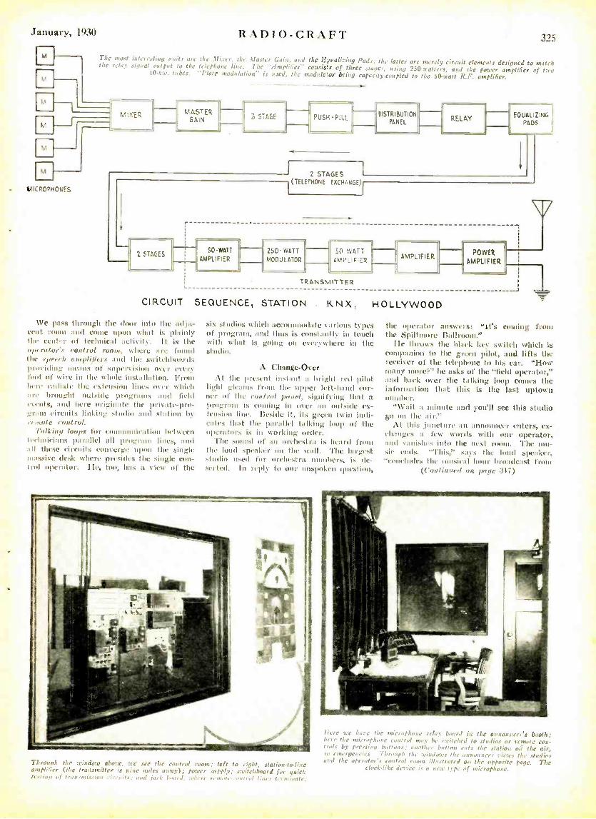
January, 1930 RADIO-CRAFT 325
The most iutrre,liuq auits ara the Mixer. the .Master Gaia, aril the L uali_ing Pad.; the latter are merely circuit elements designed to match the relay signal output to the telephone line. The "Amplifier- consists of three stapes, using 250 swatters, and the power amplifier of two 141-lite. tubes. "Plate nwd,,laliou' is used, the modeletor bring capacity-coupled to the 50 -satt X.F. amplifier.
VICROAHOSES
MIXER MASTER GAIN 3 STAGE
2 STAGES
r
PUSH-PULL
2 STAGES 1
((TELEPHONE ENCHASGE)I
DISTRIBUTION PANEL
RELAY EQUALIZING 1
PADS
SO-WATT
AMPLIFIER 250- WATT
MODULATOR
50 WATT AMPLIFIER
TRANSMITTER
CIRCUIT SEQUENCE, STATION
We pass through the door into the adja- cent room and conic upon what is plainly the cent'r of technical activity. It is the opt rit fur's coot rot rusty, (toue our found the veeeh omplifiers :old the switchboards providing beans of sop. ision us`,,' ,try foot of wire in the whole instullatinn. Frouu litre radiate the r,ten,i"n lines over which are brought outside programs and field events, and here originate the private-pro- gram circuits linking studio :nul station by it:wile eon -tru!.
Palkintl tool's for communication between teelnirimis parallel all program lines, and all these circuits converge upon the single massive desk where presides the single con - trol operator. IIe, too, has a view of the
KNX.
AMPLIFIER
HOLLYWOOD
six studios which accommodate various types of program. and thus is constantly in touch with what is going on everywhere in the studio.
A Change -Over At the present instant a bright red pilot
light _Ic :nos from the upper lett -band or- ner of the control gaud, .signifying that a program is cooling in over nil outside ex- tension line. Reside it, its green twin indi- cates that the parallel talking loop of the operators is in working order.
'file sound of an orchestra is heard front the loud speaker on the wall. 'l'he largest studio used for orchestra numbers, is de- serted. In reply to our unspoken Juestiun,
POWER
AMPLIFIER.
the operator answers: "it's coaling from the Spiltmore Ballroom.
Ile throws the black key switch which is companion to the green pilot, and lifts the receiver of the telephone to his ear. "I -Iow many nu,re'c" he asks of the "field operator," and haek over the talking loop comes the information that this is the last uptown number.
"Wait a minute and you'll see this studio go on the air."
At this ,juncture an announcer enters, ex- eta] iges n few words with oar operator, and vanishes into the nusl rooiu. The nu i,- sic ends. "'l'bi." sans nu' laud speaker, -concludes the musical hour broadcast front
((noun std nn ',ante 317)
Through the ttindow above, tee sec flic control root,; left fo right, station -lo -tint amplifier (the transmitter is aine miles array); ponter supply; switchboard for quirk lesfiug of fro: n.onir.cian , n, nits; and jack b.n,nt, nhere r, ,,,,.l, , u end tarir.. Lr,nivar,.
here ere hure the microphone relay board in the awot,Jurer's booth; hey the mie-, phone ewli cu) may be switched to studios or rende cou- rrais by pressing buffons; another button ruts the station o.ï the air, in emergencies. Through the windows the elliliMeileer views the studios and the operator's control room ill,,strutet1 on floc opposite page. The
clock-like device is a u,.r type of rnirrophonr.
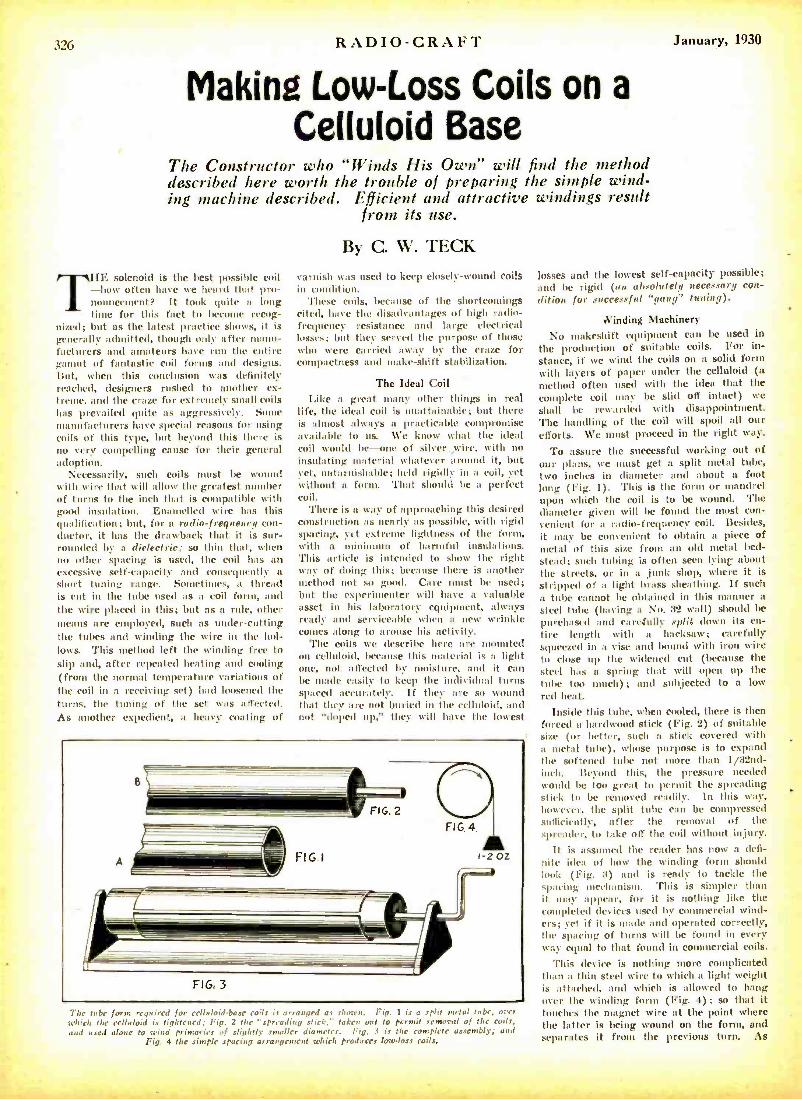
RADIO-CRAFT u:-y, 1930
Making Low -Loss Coils on a
Celluloid Base The Constructor who "Winds His Own" will find the method described here worth the trouble of preparing the simple wind- ing machine described. Efficient and attractive windings result
from its use.
T HE solenoid is the best possible coil how often have we heard that pro-
nouncement? It took quite a long time for this fact to become recog-
nized; but as the latest practice shows, it is generally admitted, though only after manu- facturers and amateurs have run the entire gamut of fantastic coil forms and designs. But, when this conclusion was definitely reached, designers rushed to another ex- troue, and the craze for extremely small coils has prevailed quite as aggressively. S manufacturers have special reasons for using coils of this type, but beyond this there is no very compelling cause for their general adoption.
Necessarily, such coils must be wound with wire that will allow the greatest number of turns to the inch that is compatible with good insulation. Enamelled wire has this qualification; but, for a radio -frequency con- ductor, it has the drawback that it is sur- rounded by a dielectric; so thin that, when no other spacing is mused, the coil has an excessive self -capacity and consequently a short tuning range. Sometimes, a thread is cut in the tube used as a coil form, and the wire placed in this; but as a rule, other means are employed, such as under- cutting the tubes and winding the wire in the hol- lows. This method left the winding free to slip and, after repeated heating and cooling (from the normal temperature variations of the coil in a receiving set) had loosened the turns, the tuning of the set was affected. As another expedient, a heavy coating of
By C. W. TECK
varnish was used to keep closely -wound coils in condition.
These coils, because of the shortcomings cited, have the disadvantages of high radio - frequency resistance and large electrical losses; but they served the purpose of those who were carried away by the craze for compactness and make -shift stabilization.
The Ideal Coil Like a great many other timings in real
life, the ideal coil is unattainable; but there is almost always a practicable compromise available to us. We know what the ideal coil would be-one of silver Hire, with no insulating material whatever around it, but yet, untarnishable; held rigidly in a coil, yet without a form. That should be a perfect coil.
There is a way of approaching this desired construction as nearly as possible, with rigid spacing, yet extreme lightness of the form, with a mini muum of harmful insulations. This article is intended to show the right way of doing this; because there is another method not so good. Care must be used; but the experimenter will have a valuable asset in his laboratory equipment, always ready and serviceable when a new wrinkle comes along to arouse his activity.
The coils we describe here are mounted on celluloid, because this material is a light one, not affected by moisture, and it can be made easily to keep the individual turns spaced accurately. If they are so wound that they are not buried in the celluloid, and not "doped up," they will have the lowest
The tube form required for celluleid'hase coils is arranged as shown. Fig. 1 a split metal tube, which the celluloid is tightened; Fig. 2 the "spreading stick, taken out to permit removal of the coils, and used alone to wind primaries of slightly smaller diameter. Fig. .4 is the complete assembly; and
Fig. 4 the simple spacing arrangement which produces low -loss coils.
losses and the lowest self -capacity possible; and be rigid (an absolutely necessary con- dition for successful "gang" tuning).
Winding Machinery
No makeshift equipment can be used in the production of suitable coils. For in- stance, if we wind time coils on a solid form with layers of paper under the celluloid (a method often used with time idea that the complete coil may be slid off intact) we
shall be rewarded with disappointment. The handling of the coil will spoil all our efforts. We must proceed in the right way.
To assure the successful working out of our plans, we must get a split metal tube, two inches in diameter and about a foot long (Fig. 1). This is the forum or mandrel upon which the coil is to be wound. The diameter given will be found the most con- venient for a radio- frequency coil. Besicles, it may be convenient to obtain n piece of metal of this size from an old metal bed- stead; such tubing is often seen lyint about the streets, or in a junk shop, where it is stripped of a light brass sheathing. If such a tube cannot he obtained in this manner a steel tube (having a NO. 32 wall) should be purchased and care.fully split clown its en- tire length with a hacksaw; carefully squeezed in a vise and hound with iron wire to close up the widened cut (because the steel has a spring that will open up the tithe too much); and subjected to a low red heat.
Inside this tube, when cooled, there is then forced a hardwood stick (Fig. 2) of suitable .ize (or better, such a stick covered with n metal tube), whose purpose is to expand the softened tube not more than I /32nd- inch. Beyond this, time pressure needed mcould be too great to permit the spreading .tick to be removed readily. In this way, however, the split tube can be compressed nftìcientl-, after the removal of time
',1mueaulcr, to take off the coil without injury.
It is assumed the reader has now a defl- nitc idea of how the winding foram should look (Fig. 3) and is ready to tackle the .pacing iimechaanism. This is simpler than it. may appear, for it is nothing like the completed devices used by commercial wind- ers; yet if it is made and operated correctly, the spacing of turns will be found in every way- equal to that found in commercial coils.
This device is nothing more complicated than a thin steel wire to which a light weight is attached, and which is allowed to hang over the winding form (Fig. 4) ; so that it touches the magnet wire at the point where the latter is being wound on the form, and separates it from the previous turn. As
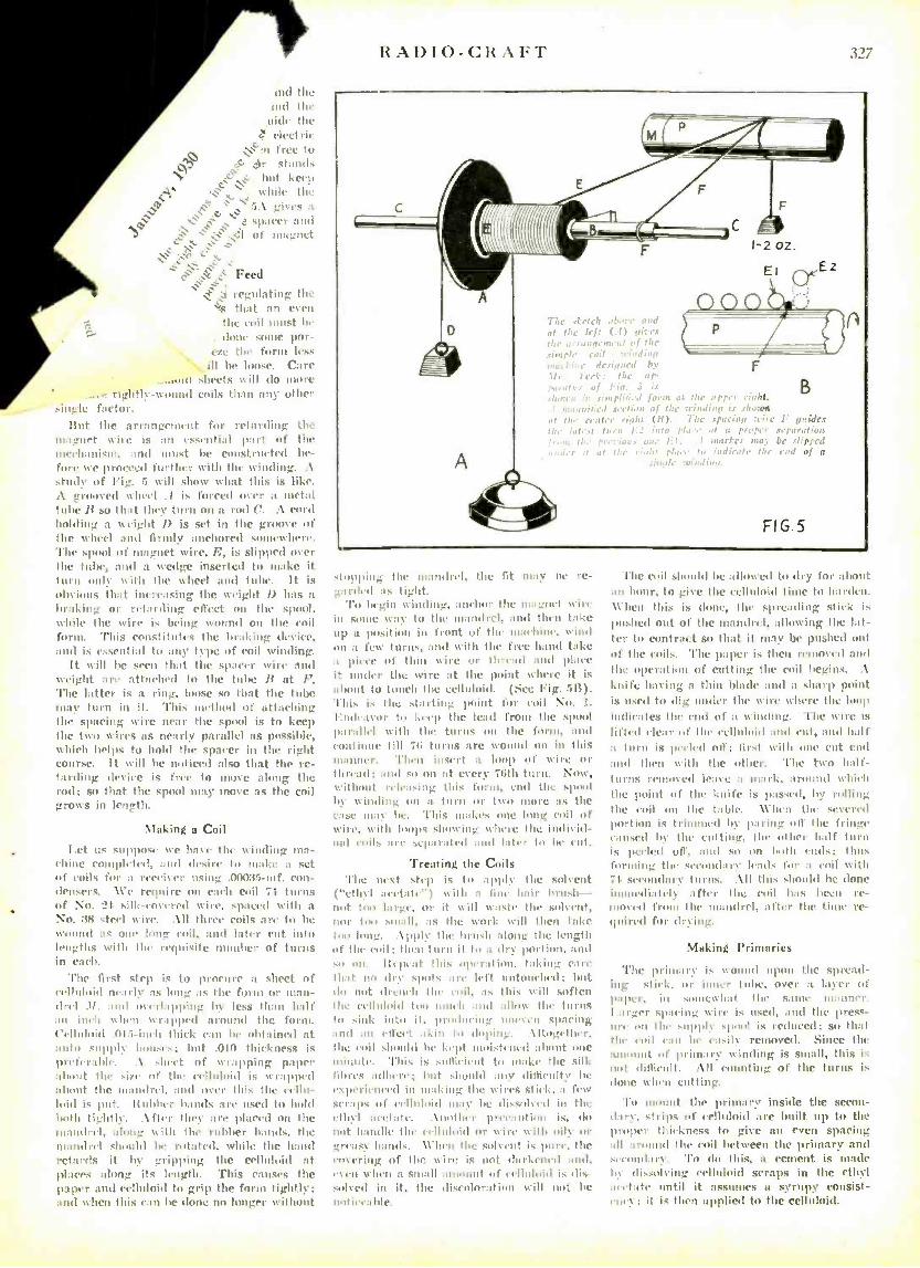
and the and the
wide the electric
r'n free to ;1r stands
1, c "`: but keep . , wwhdc two J ~ ' \ : i.1 giy CS a
' sparer and
ßìl of magnet
e`er ;is Feed
regulating the ks that an even
the roil roust be
, done songe iior- czr the form less
ill be loose. Care -.mat 1 sheets will do more
. tightly -wound coils than any other single factor.
Ilut the arrangement fuir retarding the magnet wire is an essential part of the mechanism, and must be ronstrueted be- fore we proceed further with the winding. A stripy of Fig. :ï will show what this is like. .1 grooved wheel .t is forced over a metal tube B so that they turn on a. rod C. A cord holding a weight I) is set in the groove of the %vbeel and firmly anchored somewhere. The spool of magnet t wire, F,, is slipped over the tube, and a wedge inserted to make it turn only %with the wheel and tube. It is obvious that increasing the weight I) has a braking or retarding effect on the spool, while the wire is being wound on the coil form. This constitutes the braking mking device, and is essential to any type of coil winding.
It will be seen that the spacer wire and weight are attached to the tube 13 at F. The latter is a ring, loose so that the tube may turn in it. This method of attaching the spacing wire near the spool is to keep the two wires as nearly parallel as possible, which helps to hold the spacer in the right course. it will be noticed also that the re- tarding device is free to move along the rod; so that the spool may move as the coil grows in length.
Making a Coil
T,et its suppose we have the winding ma- chine completed, and desire to make a set of coils for a recri%er using .00035 -nif. con- densers. \Ve require on each coil 71 turns of \o. t. silk -covered wire, spaced with a
NO. 38 steel wire. .111 three coils are to he wyound as our lung roil. and later cut into lengths with the requisite number of turns in each.
The first step is to procure a sheet of celluloid nearly as lung as the form or man- drel 1f, and overlapping by less than half nn inch when wvrapprd around the form. Celluloid .t115-inch thick can be obtained at auto supply houses; hut .Oln thickness is preferable. .1 sheet of wrapping paper shunt the size of the celluloid is wrapped about the mandrel, and over this the cellu- loid is put. 'Rubber bands ;tre used to hold both tightly. After they are placed on the mandrel, along with the rubber bands, the mandrel should he rotated, while the hand retards it by gripping the celluloid at places along its length. This causes the paper and celluloid to grip the form tightly; and when this can be done no longer without
RADIO -CRAFT 327
The ,feleh ab,n- and at the left t.I t sic es tie i reo,.. ;. Inc.' of the simple ,'.1 . udin,t "%I», ;1.. .:noa by ii the ap.
F
B .. r'eJ ,e,!ti,.0 of Ile ; hiding i.r .Phaarit at ,,., eure, ,lab? (1t). The ..paeiup ¡cire F .mides
, h_ :ah! t!ia co proper L.
vepnratiuu . r I. .I nwiler mai be .dipped
... ,.,6t pt to died t Mr end of a
FIG.5
slopping the mandrel, the fit uuty tie re- garded as tight.
To begin winding, antiwar the magnet wire in saute way to the mandrel, and then take up a position in front of the üaehine, wind on a few- turns, and with the free hand take a piece of thin wire or thread and place it under the wire at the paint where it is about to touch the celluloid. (tire big. fill). This is the starting point for coil No. 1.
I:ntlea%or to keep the leach from the spool parallel with the turns on the frerny :and
C011 inue till 71; turns are wound on in this manner. Then insert a loop of wire or thread; and so on at every 76th turn. NOW, without releasing this form, end the spool by winding on a turn or two more as the case nutty be. 'Phis makes one long coil of wire, with loops showing %where the indiyid-
nal rails are separated and Inter to be cat.
Treating the Coils The next stop is to apply- the solvent
( ''ethyl acetate-) %with a lino hair brush- not too large. or it will waste the solvent, nor too small, as the work will then take ¡oolong. .\pply the hrnsh along the length of the rail; then turn it to a dry portion, and
rem. lteprat this operation, taking care that no dry spots are left untouehrd; hit do not drench the rail, as this will soften the celluloid tun nitwit and allow the turns to sink into it, producing tmrwrn sparing and an etl'eet akin to eloping. \Ilogether, the coil .should be kept moistened ahuut one minute. This is ',Mikhail to hake the silk fibres adhere; but should :nn lilhirtdtV be experienced in making the wires slick. a. few scraps of celluloid nuay be dissolved in the ethyl acetate. \nothrr precaution is, do not handle the relhluil or wire with oily or greasy hands. \Churn the solvent is pure, the covering of the wire is not darkened and, even wheel a small amount of celluloid is lis- solyrd in it, the discoloration will neat be mot tumble.
The coil .should be allowed to dry for about :m hoar, to give the eellidoid time to harden. When this is done, the spreading stick k pushed out of the mandrel, :alloying the hit- ter to contract so that it may be pushed nit of the coils. The paper is then roomed and the operation of culling the coil begins. .1
knife having a thin blade and a sharp point is used to dig under the wire where the luup indicates the end of a %winding. 'flue wire is
lifted dear of the celluloid and cut, and half a turn is peeled off; first with one cut col and then with the other. 'Pave two half - turns removed kale a nunk, around which the point of the knife is passed, by rolling the coil on the table. \ \'hen the severed portion is trimmed by paring of the fringe caused by the cutting. the other half turn is peeled off, and so on bn11i cots; thus forming the secondary leads for a toil with 71 sreundar turns. .111 this should be done immediately after the coil has been re- mined from the tan drel, ¡%tier the time re- quired for drying..
Making Primaries
'l'he primary is wound upon the spread- ing stick, or inner tube, over a layer of paper, ill somewhat the same it:nnicr. Larger sparing wire is used, and the press - ure on two supply spend is reduced; so that the coil can In easily removed. Since the amount of primary %winding is small, this is
not difficult. .111 counting of the turns is lone %churn cutting.
To mount the primary inside the secon- d:ny, .strips of celluloid are built up to the proper thickness to give an even spacing
ll arnutd the coil between the primary and weoudari'. 'l'o do this, a cernent is trade by dissolving celluloid scraps in the ethyl aeet:dr until it assumes a syrupy consist- ency: it is then applied to the celluloid.
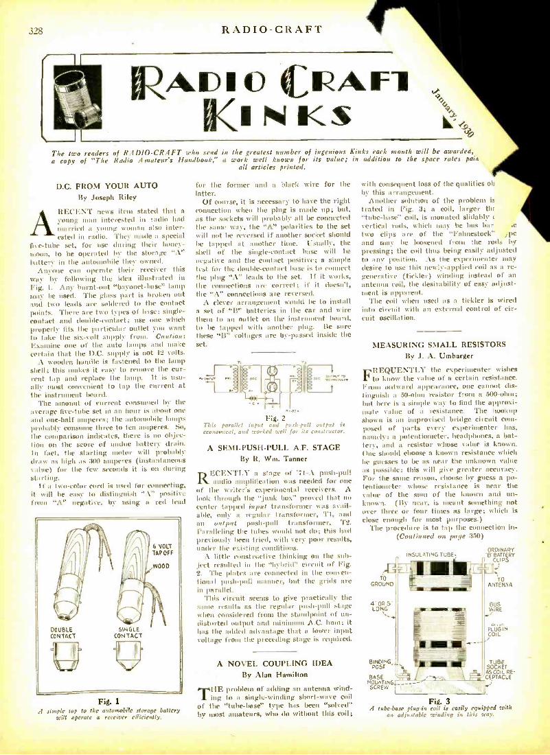
328 RADIO-CRAFT
A (CIAF1 (INKS r
The two readers of RADIO -CRAFT who send in the greatest number of ingenious Kinks each month will be awarded, a copy of "The Radio Amateur's Handbook," a work well known for its value; in addition to the space rates paia
all articles printed.
D.C. FROM YOUR AUTO
By Joseph Riley
ARECENT news item stated that a
young mutt interested in radio had married a young woman also inter- ested in radio. They made a special
five -tube set, for use during their honey- moon, to he operated by the storage "A" battery in the automobile they owned.
Anyone can operate their receiver this way by following the idea illustrated in Fig. I. Any burnt -out "hnyonet -base" lamp may be used. The glass part is broken out and two leads are soldered to the contact points. 'There are two types Of Iase; single - contact and double- eontaet; use one which properly fits the particular outlet you want to take the six -volt supply from. Caution: Examine MC of the auto lamps and make certain that the D.C. supply is not 12 volts.
A wooden handle is fastened to the lamp shell; this makes it easy to remove the cur- rent tap and replace the lamp. It is usu- ally most convenient to tap the current at the instr nt Ward.
The amount of current consumed by the average five -tube set in an I is about one and one -half amperes; the autonohile lamps probably consume three to ten amperes. So, the comparison indicates, there is no objec- tion on the score of undue battery drain. In fact, the starting motor will probably draw as high as 300 amperes (instantaneous value) for the few seconds it is on during starting.
If a two -color cord is used for connecting, it will be easy to distinguish A" positive from "A" negative. by using a red lead
6 VOLT TAP OFF
WOOD
DOUBLE CONTACT
SINGLE CONTACT
Fig. 1
A simple tap to the automobile storage battery will operate a receiver efficiently.
for the former and a black wire for the latter.
Of course, it is necessary to have the right connection when the plug is mode up; but, as the sockets will probable ;III he connected the same way, the "A" polarities to the set w ill not he reversed if another socket should be tapped at another time. Usually, the shell of the single- contact Irise will be
negative and the contact positive; a simple test for the diable- contact base is to connect the plug "A" leads to the set. If it works, the connections are correct; if it doesn't, the "A" connections are reversed.
A clever arrangement would he to install a set of "B" batteries in the car and wire them to an outlet on the instruisent hoard, to be tapped with :mother plug. Be sure these `B" voltages are by- passed inside the set.
INPUT OWN
Fig. 2 TI,is parallel input and push -pull output is economical, and worked reel for its constructor.
A SEMI- PUSH -PULL A.F. STAGE By R. Wm. Tanner
ECEN'l'LY a stage of 'Ti -A push -pull audio amplification was needed for one
of the writer's experimental receivers. A hick through the "junk box" prayed that no center tapped input transformer was avail- able, only a regular transformer, 'l'I, and an oett put push -pull transformer, '1'2.
Paralleling the tubes world not do; this had previously been tried, with very poor results, under the existing conditions.
A little constructive thinking on the sub- ject resulted in the "hybrid" circuit of Fig. 2. The plates are connected in the conven- Iion:ll push -pull manor, but the grids are in parallel.
This circuit seems to give practically the saute risulls :IS the regular push -pull stage when (insidcred from the standpoint if un- distorted output and iiininnun .N.('. bun; it h:.s the added advantage that a lower input v.ltage from the preceding stage is required.
A NOVEL COUPLING IDEA By Alan Hamilton
THE problem of adding an antenna wind - ing to it single -winding short -wave coil
of the "tube -base" type has been "solved" by most amateurs, who do without this coil;
with consequent loss of the qualities ob by this arrangement.
Another solution of the problem is
trated in Fig. 3; a coil, larger tht "tube -base" coil, is mounted slidably vertical rods, which may be Tats bar ,e
two clips are of the "Fahnestock" ,pe
and muq' be loosened front the rods by pressing; the coil thus being easily adjusted to any position. As the experimenter may desire to use this newly- -applied coil as a re- generative (tickler) winding instead of an
antenna coil, the desirability of easy adjust- ment is apparent.
The coil when used as a tickler is wired into circuit with an external control of cir- cuit oscillation.
MEASURING SMALL RESISTORS By J. A. Umbarger
FREQUENTLY the experimenter wishes to know the value of a certain resistance.
From outwan1 appearance, one cannot dis- tinguish a 50 -olui resistor from a 500-ohm; but here is it simple way- to find the approxi- mate value of It resistance. The hookup shown is an improvised bridge circuit com- posed of parts every experimenter has,
namely: a potentiometer, headphones, a bat- tery, and a resistor whose value is known, One should choose a known resistance which he guesses to be as near the unknown value as possible; this will give greater accuracy. For the same reason, choose by guess a po- tentiometer whose resistance is near the volute of the snot of the known and un- known. (By near, is meant something not over three or four times as large; which is close enough for most purposes.)
'l'he procedure is to tap the connection in- (Continued on page 351))
TO
7..
GROUND
4OR5' LONG
INSULATING TUBE, ORDINARY
B n BATTERY
TO ANTENNA
WIRÉ
PLUG IN COIL
BInDInG-, TUBE POST SOCKET
á,,ASCOiL RE
ÓUñTING / -- ^ ' \ T I
CEPTACLE
SCREW ,------
r Fig. 3
A tube -base plug -in coil is easily equipped with an adjustable winding in this way.
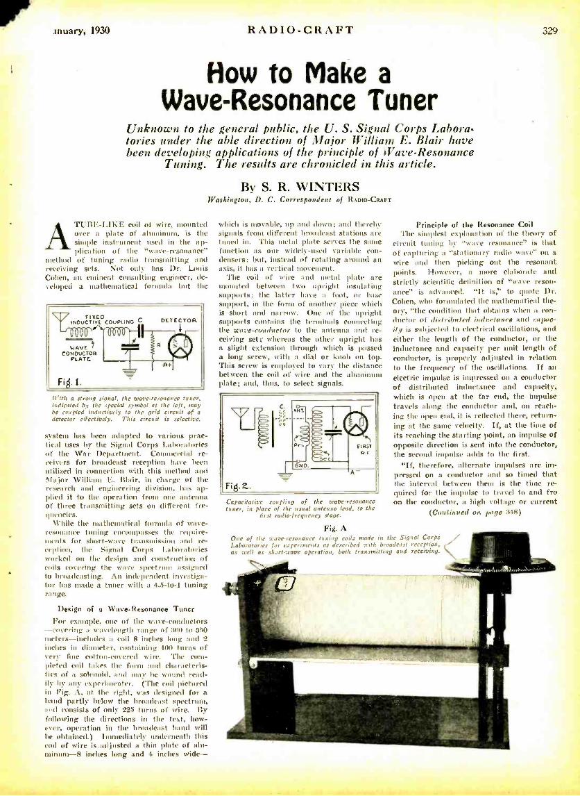
lnuary, 1930 RADIO -CRAFT
How to Make a Wave -Resonance Tuner
Unknown to the general public, the U. S. Signal Corps Labora- tories under the able direction of Major William E. Blair have been developing applications of the principle of Wave- Resonance
Tuning. The results are chronicled in this article.
By S. R. WINTERS Washington, D. C. Correspondent of RADIOCRAFT
ATUBE -LIKE coil of wire. mounted over a plate of alunninunt, is the simple instrument used in the ap- plication of the "wave-resonance"
method of tuning radio transmitting and receiving sets. Not only has Dr. Louis Cohen, an eminent consulting engineer, de- veloped a mathematical formula but the
FIXED INDUCTIVE COUPLING C
L0000' 1111
WAVE 1 CONDUCTOI
PLATE
Fikl.1.
DETECTOR
11'ith a strong sign!, the wave- resonance honer, indicated by the special symbol at the left, may be coupled inductively to the grid circuit of a detector effectively. This circuit is selective.
system has been adapted to various prac- tical uses by the Signal Corps Laboratories of the War Department. Commercial re- ceivers for broadcast reception have been utilized in connection with this method and Major William E. Blair, in charge of the research and engineering division, has ap- plied it to the operation from one antenna of three transmitting sets on different fre- quencies.
While the mathematical formula of wave - resunanec tuning en passes the require- ments for short -wave transmission and re- ception, the Signal Corps Laboratories worked on the design and construction of coils covering the wave spectrum assigned to broadcasting. An independent investiga- tor has made a tuner with a 4.5 -to-1 tuning range.
Design of a Wave - Resonance Tuner For example, one of the wave- conductors
-- covering a wavelength range of :310 to 550 meters -includes a coil 8 inches long and 2 inches in diameter, containing 400 turns of very fine cotton -covered wire. 'T'he com- pleted coil takes the form and characteris- tics of a solenoid, and may he wound read- ily- by any experimenter. (The coil pictured in Fig. A, at the right, was designed for a band partly below the broadcast spectrum, amyl consists of only 225 turns of wire. 13y
following the directions in the text, how- ever, operation in the broadcast hand will he obtained.) Tuntediatel- underneath this cod of wire is.adjnsted a thin plate of alu- minum-8 inches long and 4 inches wide-
which is movable, up and down; and therein. signals from different broadcast stations arc tuned in. This metal ¡date serves the same function as our widely -used variable con- densers; but, instead of rotating around an axis, it has a vertical movement.
The coil of wire and metal plate are mounted between two upright insulating supports; the latter have a foot, or base support, in the form of another piece which is short and narrow. One of the upright supports contains the terminals connecting the wore- conductor to the antenna and re- ceiving set; whereas the other upright has a slight extension through which is passed a long screw, with a dial or knob on top. This screw is employed to vary the dist;once between the coil of wire and the aluminum plate; and, thus, to select signals.
Capacitative coupling of the ware. resonance tuner, in place of the usual antenna lead, to the
first radio -frequency stage.
Fig. A One of the ware -resonance tuning roils made in the Signal Corps Laboratories for experiments as described with broadcast reception, as well as short .rare operation, both transmitting and receiving.
l
Principle of the Resonance Coil The simplest exphmation of the theory of
circuit tuning by "wave resonance' is that of capturing a "stationary radio wave" on a wire ;Intl then picking out the resonant points. I-Iowever, a more elaborate and strictly scientific definition of "wave reson- ance" is advanced. "It is," to quote 1)r. Cohen, calao formulated the mathematical the- ory, "the condition that obtains when a con- ductor of distributed inductance and capac- ity is subjected to electrical oscillations, and either the length of the conductor, or the inductance and capacity per unit length of conductor, is properly adjusted in relation to the frequency of the oscillations. If an electric impulse is impressed on a conductor of distributed inductance and capacity, which is open at the far end, the impulse travels along the conductor and, on reach- ing the open end, it is reflected there, return- ing at the same velocity. If, at the time of its reaching the starting point, an impulse of opposite direction is sent into the conductor, the second impulse adds to the first.
"If, therefore, alternate impulses are im- pressed on a conductor and so timed that the interval between them is the time re- quired for the impulse to travel to and fro on the conductor, a high voltage or current
(Continued on page :348)
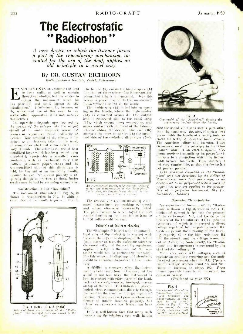
R. \1)10 -CRAFT
The Electrostatic "Radiophon "
A new device in which the listener forms a part of the reproducing mechanism, in- vented for the use of the deaf, applies an
old principle in a novel way
By DR. GUSTAV EICHHORN Radio Technical Institute, Zurich, .Switzerland
in castling the deaf to hem' radio, as well as certain theoretical studies, led the writer to design the instillment which he
has patented and made known as the "It:ttliuphon." (hltfortmatel, treatise of the widespread use of this word to de- scribe other apparatus, it is not suitably distinctive.)
Its operation depends npuu connecting the p, cxon. of the listener into the output circuit of an audio amplifier, titer. the phones or reproducer would ordinarily he located. Onr terminal of the circuit is at- tached to an electrode taken in the hand, or 5111111 Othrr tIret rirai IbIn11Y'ti011 to the body is made. The other is connected to a
metallized Myer which has been coated upon a dielectric (preferably a so- called semi- conductor, such as parchuunt, very thin leather, parchment paper, etc.); and the nun -metallized side of this diaphragm is
held, by the aid of an insulating handle, against the ear. No special polarity is re- quired; though hi pra,(uIe, at times, better results may be had by reversing connections.
Construction of the "Radiophon" l'he instrument. illustrated in Fig. A. is
shown in cross -section in Fig. 1; while a front tirw of the handle is given in Fig. 2.
Fig. I (left) Fig. 2 (right) .Side and front cras.r.rectimu of the "Radin - ¡l oi, The principal parts are named in the
text.
l'hr handle (3) encloses a hollow space (4) like that of the c: l -pirtr of an European tele- phone, but this is not essential. Over this l'eccss is placed the "dielectric membrane," its torbolli:ed sit le (í) on the inside.
The double wire (12) k It'd into an 011111-
jug in the handle, where the high- resistor (15) is connected across it. One output lead k connected also to the metal .strip (17), which covers these connections and makes contact with the hand of the listener, who is holding the device. 'l'br wire (18) connects the tither output lead to the utetal- ized side of the dielectric diaphragm (5-8).
OSC. / VC ArT.
SW RADIODNbN
A/
FIC.3 RI
220 V.
6 LISTENER
.h, experimental circuit, with controls de, :onnf test thc characteristics of the "RndLopli n.
b 1, exact, the listener is one pla1, ,.i the con. deuer, as nee/i as a ,,..L,tr.
The resistor (of say 100,O00 ohms) elimi- nates unsteadiness or breaking of speech and music, otherwise occasionally noted. The plate snllage tu he employed for hest results drprnds mn the tube; but at least 70 lu lull volts should he usai.
Principle of Indirect Hearing
The '1fadiophun" is held with the unmetal- lized side of 1114. dielectric in contact with the ear; the dryer the diaphragm, the better (as a matter of fart, the dielectric might he dispensed with, and the metallic lrenthr :tnc applied directly to the ear; but the sen- sation would not be particularly pleasant). For this reason, the diaphragm, if absorbent, should be varnished to prutcet it from mois- ture.
Audibility is strongest when the instru- ment is held very close to the car; but the sound is not lost when the instilment is held in contact with other parts of the head, such as the cheek, tel fu urhea tl, or is en on lop of the head. 'Phis indicates a phcsio- logical effect coannunit :ted directly through the head to the sensitive interior organs of hearing. Thus, churn deaf persons whose ear- drums no longer function properly, but :dome Nerve - ,vvflrrs are ¡Wort, call hear radio.
It is a well-known fact that many such persons use the telephone very- well; in this
January, 1930
Fig. A Onc model of the "Radiophoa." shnadrg the
reproducing surface above the habdle.
case the sound vibrations seek a it other than the usual one. So, also, if such a deaf person holds the handle of a tuning fork tie - tween his teeth, he hears the sound clearly. The American editor and inventor, Hugo Gernsback, used this principle in his "Oso- phone"; which is an electromagnetic tele- phone receiver transmitting its powerful vi- brations to a projection which the listener holds between his teeth. This, however, is not very comfortable, so that the device has not proven popular.
(The principle embodied in the "Radio - phon" was also described by the Editor of It.tuto-('a.ttr, some four dears ayo, as an experiment to be performed with a sheet of paper: bu woe not applied to the produc- tion of a perfected instrument, like Dr. liichhori's.- Editor.)
Operating Characteristics
An experimental hook -up of the "Radio - 11i, ' is shown in Fig. :3, wherein the A. F. modulated current is fed into the primary of the variocouplcr 'VC, and thence to the primary of the transformer AFT; upon the secondary of which is impressed a direct voltage regulated by the potentiometer Itl. Switches permit the
the of the (dock-
ing capacity C or the high resistance 112
into the circuit; and the voltage across the uutpul . \ -I; (and, consequently, the "It:olio- Ihon" and its operator) is measured by the ei.etrostatie voltmeter V.
With eery w'rak A.C. voltages, such as oper:t4' tin ordinary receiving set, the audi- ble effect commences when the D.C. ("polar - izing') voltage reaches about 70, and con- tinues to increase to about 150. From Ihtnee upwards there is no important in- crease in volume.
(Continued on page 350)
Fig. 4 77:r characteristics of the "Radiophon" under dif- ferent polarir,iup and signal voltages, as fleas.
red by the cirerait shown in pin. 3. To some estent, thc sen- sitivity increases with the D.C. voltage applied.
1
January, 1930 It.AI)IO-Clt.AP"I' 3
The Radio Craftsman's Own Paffe In these columns will be found letters of RADIO -CRAFT readers from every quarter of the globe. Here old friends will
renew acquaintances of long standing.
SHORT -WAVE "SKEDS" Editor, RADIO -CRAFT:
I can give some of the information asked for in your last issue. The Mexican station is XD.\ at Chapultepec on about 15.85 meters. \'PD at Suva works on 20.795 and 31.3, and is owned by Amalgamated \Vireless of Australasia.
The Siamese do not seem to be working on the schedule given by Mr. .\scutachinta and the . \. 14. R. L.; they are heard here most any day from 1 p. m. on. They work I M;W, Natters, mostly; very little English is used, though they have been heard greeting the United States.
VK2ME on 15.5 meters is working GBX, Eng- land. on 18.56 and 24.5; VK3\IE has been tem- porarily discontinued.
The Swedish chain programs are being beard near 50 meters at 11 p. m. The German station working X11:\ is DM; the sane transmitter as DG\\-, but on 15.02. The Zeesen station is com- ing in fine on 31.38 and I am informed that this is the station which will be used for the exchange of programs with the N. B. C. Their schedule is now 8 -9 a. m. and 2 -4:30 p. m.
IIKCJ at Manizales. Colombia, is on 35 meters. KIM( at Manila, P. I.. on 24.5 meters has come through here twice and gives promises of reaching the eastern U. S. fairly well this winter.
Perhaps the most consistent station, at the be- ginning of November. is VRY, Georgetown, British Guiana, on 43.86, Wednesdays and Sundays. They generally sign off at 9 or 9:15 p. m., not 10:15 as your letter states.
Saigon, Indo- China. will be operating on 18.75 in December; the address is Boite Postale 238, Saigon. G2NM, Caterham, England. is expecting a permit to work on 20 meters soon. SRI!, Heredia, ('osta Rica, will have 150 watts instead of his former 7 yi.
KIO, Kahuhu, Hawaii, sends a verification; they are on 25.68 meters with 1 kw. power; they work telephony with KES 28.80 and KOJ 16.61, Bolinas, Calif.
It may interest some of your readers that there is a Short- Wave Club of short -wave fans in the United States. For information, they may write me.
ARTHUR J. GREEN, 700 Alpha Street.
Kioudyke, Ohio.
SUCCESS IS COMPARATIVE Editor, RADIO -CRAFT:
In your November issue you ask for experiences with short -wave adapters. I have not been success. ital. but will give you my experiences. I pur- chased one of the short -wave adapters and gave it a trial, but had poor success. I then took it down, practically, went over all contacts and thoroughly cleaned and tightened them. Then it worked reasonably well.
I am using an RC.\ "41." with an inside 42- foot aerial of No. 18 nubbcr- covered wire just stapled to the rafters in the attic, and the usual g d.
I have received on the loud speaker, in the last two weeks, the following:
\\'ND, Deal, N. J.. (and floulton, Maine), work- ing (MS, Rugby, England. Transatlantic phone on several wavelengths; \V( )O. I b-al. N. J.. test- ing with \VSCU; \ \'2N K, \V2X. \I), \V2X. \F, W2XO, Schenectady; \VSX K. W8 X.\Y, Pitts.. burgh ; \W2XE, Richmond Hill. N. V.; \\'9X F. I low ners Grove, Ill.; W9N. \. \ W9 EL Chicago; \V9N.\E, M. ajolis; W('K. I)otroit Police De- partment; Radio -Vitus, Paris, calling New York.
I don't know whether this is D
t tv or not; but l
use over my '27 detector tube a small shield, grounded to the frame of the chassis. I first throw the tube into full oscillation, and then tune in all stations and pass such as show code, or other than phone or broadcasting. I then drop back below oscillation and pick up those stations that are other than code. I like to read about others' achievements.
C. M. McFATRIDGE, Moravia, Iowa.
(Some of our readers would like to swap their success for Mr. McFatridgé s lack of success. - Editor.)
HAM DOPE WANTED Editor, RADIO- CR.IFT:
I have built the "Sun" short-wave tuner dc- scribed in your September issue, and have had very tine results with it. On Sept. 2 I received \\'2N A sery loud, and on September 3, 1.1'0 on 19 meters. I have always received distant "hunts."
I think of RADIO -CRAFT as the best magazine that can be had; but I do think it would be much better if you published more short-wave receivers and transmitting dope and diagrams for the hams.
A "near " -in -the- future ham, JOHN F. S\IITIt,
2705 So. Avers Avenue, Chicago, Illinois.
(With its enlarged size, RADIOCRAFT trusts to be able to give every subscriber more of the material that interests him most, personally. We shall wel- come all readers letters -even though it will be impossible to find room for most of them. unless they give information valuable to others -because expressions of preference are what the editor relics upon as a guide when allotting the amount of space to be devoted to each department.-Editor.)
THE letters of encouragement and praise which our readers have been
showering on us have been very welcome to the Editors of RADIO -CRAFT, and they take this opportunity of acknowledg- ing the great number to which it has been impossible to reply personally, much as they would have liked to do so. This is YOUR magazine, and it will welcome every letter which expresses a definite wish for a certain line of editorial in- formation.
We trust to make this Craftsman's page the stamping ground of those who like to follow out their own ideas and do some- thing a little different. What have you found out for yourself that will help along other experimenters? Write to the Editor of RADIO -CRAFT and tell your story in your own words.
A SOURCE OF THRILLS Editor, R:IDIO- CR:IFT:
Speaking of thrills in short -wave reception, I received one the evening of October 8 that I won't forget very soon.
I am using an improved ID.T short -wave receiver, which I constructed myself, and have been getting very good results from it. On this particular ev ' g, mentioned above. I was outing around on the 25 -to-50 -meter band, and picked up some phone station calling \VOO. These signals came in quite loud and clear and I presently heard the voice say: "This is \WSBN culling WOO." I then hooked up these call letters and found, to my great surprise, them to be those of the S.S. Leviathan. It was 11:18 p. m., when I picked the ship tip, and I was able to understand everything; despite the fact that weather conditions were not good and there was quite a good deal of static. 'Phis came in on about 42 meters.
I have been unable, however, to find out where station WOO is located, although I have listened to that station a number of times. Signals from station WOO come in very- good, I being able to receive them on loud speaker at any time.
Would appreciate it very much if you would give me this information and oblige.
HOWARD S. 111NM.AN, 461 N. 6th St..
Chillicothe, Illinois. (The broadcast station WOO, Philadelphia, was
given up more than a year ago, and the call has been assigned to a station erected by the A. T. & T. Co. at Deal. N. J. It is a 20 -kw. transmitter oper- ating on 3,124, 4,116, 6,515 and 8,630 -kc., 20 -kw.- Editor.)
INFORMATION TO EXCHANGE Editor, RADIO-CRAFT:
I am a short -wave fan with three years' experi- ence. I would like to communicate with other S -W enthusiasts, and especially with those who have built the "Space- Charge Autodyne." I should like to hear of their results, as I contemplate build- ing one of those receivers. With my present set, which is an improvement on the "Junk- Box," I have heard G5S \W, F\\-3, í'C6, 1'111, PC L, W6XN, CJRX, D11C, NRII, I'CJ and PLF.
CHARLES ZEL.\ITES, P. 0. Box 165,
Lincoln, N. II
31
Editor, RADIO -CRAFT: I am a double subscriber (i.e., two copies for
scrap -book tiling) to RADIO- CRAFT; it fills a need for the unattached, sideline builders and experi- menters not found in other publications. We spend a lot of money for parts, and we are sorely in need of such a magazine. Mr. Gernsback, we salute you.
I am building Mr. Fitch's band selector and, since Acme transformers are hard to obtain here, I tried rolling my own. Results were unsatisfactory. I want to get in touch with someone who has tried the choke -and -leak or "T. A. T." system; perhaps we may benefit by exchange of ideas. Mr. Fitch's "1930" electric, battery -operated, should make an excellent car set. I invite experimenters to write or phone me.
RAYMOND CORDER, "Skyline 9978,"
362!, Eleventh Ave., San Francisco, Calif
HOME -WOUND COILS Editor, RADIO- CR.IFT:
Your magazine is apparently making itself felt in the radio profession. Each month's issue seems better than ever. Congratulations!
I was interested in Mr. Sutton's article on three - circuit tuners, in the August issue; his last sentence gives much room for thought. Why is it that much of the high -priced and widely -advertised ap- paratus fails miserably on actual test, compared with crudely designed and home -made contraptions?
(king in need of a good all -round three -circuit tuner, for use in small sets for battery operation in a rural district, I tried several well -known makes. In each case the results were disappoint- ing. In disgust, I decided to wind my oven coils. using any old cardboard tube, having no regard for low -loss construction, and (I must confess) being none too fussy as to general appearance. The results, however. were most encouraging and far ahead of any of the commercial tuners for which so much is claimed by the manufacturers.
My chief trouble with the latter had been lack of sensitivity, which I think I overcame in my own coils by increasing the amount of wire in primary and ticklers.
I have always had the greatest respect for the output of the laboratory, being by no means an advocate of rule -of -thumb methods against scientific research; but my confidence has been rudely shaken by these comparisons. Are the advantages claimed for low -loss construction. space- winding, air dielec- trics, etc., grossly overrated after all?
SYDNEY E. THORNE, Thorne & Clinton, Radiotricians,
Springfield, N. B., Canada,
(The commercial coil, like the commercial re- ceiver, has been designed with the paramount idea of meeting conditions in cities and towns, where there is radio congestion and sensitivity is a curse, unless accompanied by the highest selectivity. Mr. Thorne's home -built coils would probably be of doubtful utility in Chicago or New York, though far superior for use in his own community. - Editor.)
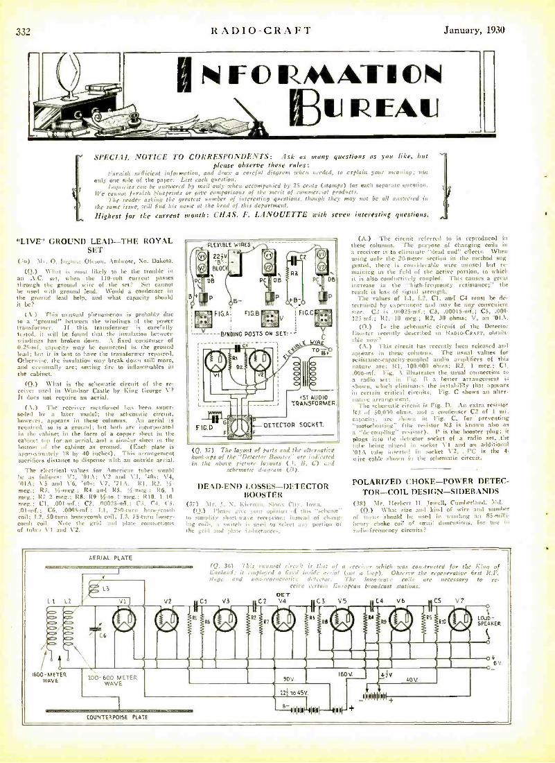
33_' RADIO -CRAFT January, 1930
N F O RACAL-11C% ILI REM.]
SPECIAL NOTICE TO CORRESPONDENTS: Ask as gunny questions as you like, but please observe these rules:
Furnish .ur ITiclent information, and Jr.,;,' a careful diagram when needed, to explain your meaning; Luse
only one side of the paper. List each question. Inquiries ran be unr Bred by mail only when accompanied by 25 cents (stamps) for each separate question.
Ile cannot furnish blueprints or give comparisons of the merit of commercial products. 77he reader asking the greatest number of interesting questions, though they may not be all answered in
the same issue, will find his name at the head of this department.
Highest for the current month: CHAS. F. LANOUETTE with seven interesting questions.
"LIVE" GROUND LEAD -THE ROYAL SET
0o) Mr. I Ingmar (0. sun, Ambrose, No. Dakota.
(Q.) \ \-hat is must likely to he the trouble in an A.C. set, when the 110 -colt current passes through the ground wire of the set? Set cannot be used with ground lead. Would a condenser in the ground lead help, and what capacity should it be?
(.\.) This unusual phenomenon is probably due to a "ground" between the windings of the power transformer. If this transformer is carefully tested, it will he found that the insulation between windings has broken down. :\ fixed condenser of 0.25 -ntf. capacity may be connected in the ground lead; but it is best to have the transformer repaired. Otherwise. the insulation may break down still more, and eventually arc; setting lire to inflammables in the cabinet.
(Q.) What is the schematic circuit of the re- ceiver used in Windsor Castle by King George V? It does not require an aerial.
(.\.) The receiver mentioned has been super-: sale! by a later model; the schematic circuit, however, appears in these columns. An aerial is required, so is a ground; but both are incorporated in the cabinet in the form of a copper sheet in the cabinet top for an aerial, and a similar sheet in the lento,,, of the cabinet as ground. (Each plate is approximately IS by 40 inches). This arrangement sacrifices distance to dispense with an outside aerial.
The electrical values for American tubes would he as follows: VI, '01A; \'2 amp V3, '40s; V4, 'OIA; V5 and Ve, '40x; \7, '71A. Rl, R2, !i- meg.; R3, '4-meg.: R4 and 125, í -mega; It ,. 1
mega; R7 2 meg.; RS, R9 "',-to 1 meg.: R1'I, 1 10. nteg.: Cl. .001 -mf.: C2, .00025 -mf.: C3. Cl, C>. .Ol,nf.: ('fi, .0005 -mf.: T.1, 2511-turn honeycomb coil; 1.2. 50 -turn honeycomb coil; 1.3. 73-turn honey- comb coil. Note the grid and plate connections of tubes VI :,,.d V2.
.-FLEI(IBLE WIRES'
W
2
PC
B
22íV. B'-
BLOC
s-
DB
p
+ -.
B-
PC ; DB
IIP
1
P
Râ
+B
ó FICA cIGB V
BINDING POSTS ON SET--
L _
FIG D
F
C2
pC'^OB
FIGC
C f WIRE TO 4,
(ST AUDIO TRANSFORMER.
- DETECTOR SOCKET.
(Q. 37) The layout of parts and the alternative hooka, rs of the "Deler'r li,ast, r" are indicated in the above picture lat,mte- f.l, !f, L) and
schematic din,un (fl).
DEAD -END LOSSES-I)ETECTOR BOOSTER
(37) -Alt. T. N. Kiernan, Sinux ("it), To Al.. (Q.) Please gin opinion of this "scheme.'
to simplify short ,n " reception: instead o1 chang- ing coils. a switch .i' user tu -'ilea :my portion of the gril and
switch inductances.
(A.) The circuit ref, 7, 1 to is reproduced in these columns. The puns.se of changing coils in a receiver is to eliminate "dead end" effects. \Allen using only the 20 -meter section in the method sug- gested, there is considerable wire unused but re- maining in the field of the active portion, to which it is also conductively coupled. This causes a great increase in the "high -frequency resistance;" the result is loss of signal strength.
The values of LI. 1.2, Cl, and C4 must be de- termined by experiment and may be any convenient size. (72 is .00025 -mi,; C3, .00015mf,; CS, 000 - 123 -of.; Rl, 10 mug.; 122, 30 ohms; V, an '01:1.
(Q.) is the schematic circuit of the Detector Iluushr recently described in ItAoto- CRAFT, obtain- able non'
(A.) This circuit has recently been released and appears in these columns. The usual values for resistance- rapacity -coupled audio amplifiers of this nature are: R1, 100.000 ohms; R2, 1 meg.; Cl. .006 -mf. Fig. .\ illustrates the usual connection to a radio set; in Fig, It a better arrangement is shorn, which eliminates the instability that appears in certain critical circuits. Fig. C shows an alter. native arrattgvment.
"Fhe schematic circuit k Fig. D. :\n extra resistor 123 of 50,0)1 ohms, and a cg mdenscr ('2 of I nut. capacity", are shown in Fig" C, for 'preventing "motorbo:ttiug" fthe resistor R3 is known also as a ".le-coupling" resistor). P is the booster. plug; it plugs into the detector socket of a radio set, the tube being placed in socket \'I and an additional '01:\ tube inserted in socket V2. . I'C is the 4-
wire cable shown in the schematic circuit.
POLARIZED CHOKE -POWER DETEC- TOR -COIL DESIGN -SIDEBANDS
(3S) Mr. Tlerbert 1T. Jewell, Cumberland, Md. (f).) What size and kind of wire :uu! number
of turns should be used in winding an 55- milli- hrnry choke coil of -'mail dimensions. for use in
radio frequency circuits?
AERIAL PLATE
L3
L 1 L2 v1
(Q. 36) 1 his unusual eimait is that if a .ec,,;,-r whirl, ;cas constructed for the K6,q of Englund: it co,plrrrrd a fixed inside aerial (ouf a Inapt. O bscr ; the regenerative first R.F. suant turd unnrepeaerati ;r detector. 7 br lone-wan roil, arc necessary to re-
c,ire n r.,..,: European broadcast stations. DE T
V2 Cl V3 C2 V4 C3 V5 C4 V6 CS V7
LOUD - SPEAKER
C6
1600-METER WAVE 200-600 MFTf:
WAVE
I80V. 4ÌV 40 V.
22 To 45V.
COUNTERPOISE PLATE ITU I'III --II'U
1 I fl!IEIEhI
+
4 6 v.
January, 1930 RADIO -CRAFT
LET RCA INSTITUTES START YOU ON THE ROAD TO.... SUCCE S S IN RADIO
Radio needs you ... That's why the entire Radio industry is calling for trained men ... That's why thousands of men who answered these advertisements are now earning from $2,000 and up a year. Radio is thrilling work ... easy hours, too, vacations with pay and a chance to see the world. Manufacturers and broadcasting stations are now eagerly seeking trained RCA men ... Aviation and
radio in the movies also provide innumer- able opportunities ... Millions of sets need servicing ... thousands of ships require ex- perienced operators ... Never before was there an opportunity like this.
This is the Only Course Sponsored by Radio Corporation of America
RCA sets the standards for the entire Radio industry ... The RCA Institutes' Home Laboratory Training Course enables you to quickly learn all the secrets of Radio ... In your spare time, in only an hour or so a day, you can obtain a thorough, practical educa- tion in Radio ... You get the inside info', mation, too, because you study right at the source of all the latest, up-to-the-minute developments. RCA, the world's largest Radio organization sponsors every single detail in this course. You learn Radio by actual experience with the remarkable outlay of apparatus given to every student. You learn the "How" as well as the "Why" of every Radio problem, such as repairing, installing and servicing fine sets. That's why every graduate of RCA Institutes has the experience. the ability and the con- fidence to hold a big -money Radio job.
Raclin Mechanic and Inspector $1800 to $4000 a Year.
1),oudeast 11.1 non Meth -
$180010 $3600
Land Station Operaror$1800 to$4000aYcar.
1i, oo.lcost Ohcr- woes $1800 to $4800 a Year.
For the added convenience of students who prefer a Resident Study Course, RCA Institutes, Inc.. has established Resident Schools in the following cities:
New York 326 Broadway Boston, Mass. . . . 599 Boylston St. Philadelphia, Pa. . Chestnut St. Baltimore, Md. . 1215 North Charles St. Newark, N. J. 560 Broad St.
Graduates of both the Home Laboratory Training Course and the Resident Schools receive exactly the same training and enjoy the same privileges so fat as jobs and salaries are concerned. And every Home Study graduate Tilly also attend any one of our resident schools for post -graduate instruction at no extra charge.
Graduates of RCA Institutes Find It Easier to Get Good Jobs
They arc closest to the source of Radio's greatest achievements because the progress of Radio is measured by the accomplishments of the great engineers in the huge research laboratories of the Radio Corporation of America.
Students of RCA Institutes get first -hand knowledge, get it quickly and get it complete. Success in Radio depends upon training and that's the training you get with RCA Insti- tutes. That's why every graduate who de- sired a position has been able to get one ... That's why graduates are always in big demand.
Study Radio at the Oldest and Largest Commercial Training Organization in
the World
Send for our Free Book . or step in at one of our resident schools and see how thousands of men are already on the road to success in Radio. Remember that you, too, can be successful ... can speed up your earning capacity . . . can earn more money in Radio than you ever earned before. The man who trains today will hold down the big -money Radio job of the future. Come in and get our free book or send for it by mail. Everything you want to know about Radio. 40 fascinating pages, packed with pictures and descriptions of the brilliant opportunities in this gigantic, world -wide money- making profession.
See for yourself why graduates of RCA In- stitutes now occupy thousands of well -paid positions. These positions are usually avail- able in from 3 to 10 days after graduation for men who can qualify. RCA Institutes will back you up to the limit. Our catalogue is yours free ... SEND FOR IT TODAY!
Clip this Coupon NOW!
rS.ossosru r
RCA INSTITUTES, INC. Formerly Radio Ittditlite of America
RCA INSTITUTES. Inc. Dept. RC -I. 326 Broadway. N. Y.
Gentlemen: Please send me your FREE 40 -page book which illustrates the brilliant opportunities in Radin and describes your laboratory - method of instruction at home!
Name
Address
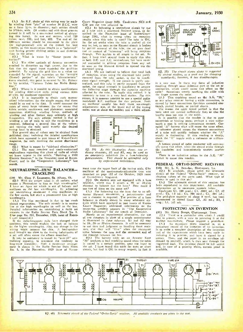
334 RADIOCRAFT January, 1930
(A.) An R,F. choke of this rating may be made by winding three "pies" of number 34 S.C.C. wire on a form A -in. in diameter; each section should be 3 /16 -in. wide. (A wooden rod with three grooves turned in it will be a convenient method of obtain- ing this form). In one end section, wind 750 turns; next, 700; and last, 800. The end of the 800 -turn section should be connected to the plate (or high -potential) side of the circuit for best results; as this construction results in a "polarized"
having greater choking action in one direction than in the other.
(Q.) %That is mean by "linear power de- tection?"
(A.) The older methods of detector connection resulted in distortion on high power, due to the fact that the signal input exceeded the grid -bias potential. By raising the grid bias to a value not exceeded by the signal, operation on the "straight (linear) portion" of the tube's "characteristic"
curve resulted; this point is covered by Mr. Palmer in his articles, "Vacuum Tubes for Radio Recep- tion."
(Q.) Where is it possible to obtain specifications for winding short -wave coils, using various sizes of wire, for condenser capacities?
(A.) It is impossible to obtain such system- atized information; for the simple reason that there would be no end to the data. It would consume the space of many large volumes; for the reason that tabes, aerials, condensers, coil placement, associated apparatus, shielding, winding forms, methods of winding and other factors vary critically at high frequencies. The only reliable method is that of winding a set of coils to suit the conditions in a receiver, following a general idea of the values; and varying the coils until exactly the desired tuning band is obtained.
This general idea of values may be obtained from published data; including the detailed specifications which have appeared in past issues of RADIO -CRAFT magazine, for coils covering the entire short -wave range.
(Q.) What is meant by "sidehand elimination?" (A.) The most complete and easily -understood
explanations regarding this phase of radio of which we know appear in the article, "Building a 1930 Electric Receiver." in the November issue of RDIO CRAFT, and in the "Cooperative Laboratory" last month.
NEUTRALIZING -HUM BALANCER - CRACKLING
(39) Mr. Chas. F. Lanouette, St. Albans, Vt. (Q.) With the proper tubes in all sockets, what
causes a Neutrodyne to hiss on high wavelengths? I have an Apex set which is out of balance and oscillates on the low wavelengths. By adjusting the neutralizing condenser I stop oscillation on the low waves, but start a pronounced hiss at high wavelengths.
(A.) The hiss mentioned is due to too much circuit regeneration. The only remedy is to neutra- lize at the high wavelengths as well as the low. ]retailed information on neutralizing a radio set appears in the Radio Service Data Sheet No. 8. (See page No. 251, December, 1929, issue of RADIO-
RAFT magazine.) If the radio -frequency coils have changed their
positions, this would explain the lack of balance on the higher wavelengths. Also, any change in the wiring might account for this. A loud- speaker curd brought too close to the tuning inductances of a set will often cause the effects described.
It may be necessary to install an "over -all" neu- tralizing capacity, to overcome the tendency to long -wave instability. Such a condenser arrange- ment is shown in the Radio Service Data Sheet No. 5, in the November, 1929 issue of RAoto-
CRAFT Magazine (page 208). Condensers NC3 and C20 are the two referred to.
(Q.) In balancing a neutrodyne circuit by use of a tube with a shortened filament prong, as de- scribed in the November issue of RADIO -CRAFT (page 239), what is wrong when no reception results when this tube is used? The tube is OK, for the set works when the tube is pushed all the way in; but, as soon as the filament circuit is broken by partial removal of the tube, the set goes dead and no amount of "trimming" will bring reception through. This applies to all stages in the set. In fact, I have tried several times to apply this idea in both D.C. and A.C. neutrolynes, but have never yet succeeded in getting reception from any set as soon as the filament circuit is opened via the shortened prong.
(A.) We are inclined to believe that total lack of reception, when using the shortened tube partly removed from the tube socket, is due to insuffi- cient signal strength. If the circuit is partly neu- tralized, and this tube is partly removed from the socket. the signal strength is insufficient to actuate the following stage through the capacity coupling afforded by the tube. To apply this method, it is necessary to tune in a very loud station. For this reason, it is common practice to use a special audio- modulated R.R. oscillator for this purpose. Such an oscillator usually has only three wavelength adjustments: one, at the lower end of the tuning scale; one at about the middle; and a third adjust-
W
Zh U
(Q. 39) As this illustration shows. two or- dinary rheostats, R1 and R2, may be used as an emergency substitute for a hum-balancing potentiometer. This should be attempted only
by experienced technicians,
ment near the upper limit of the tuning scale. (An oscillator of the continuously- adjustable type was described on page 152 of the October, 1929 issue of RADIO-CRAFT Magazine.
(Q.) On electric sets not equipped with a hum adjuster, where can I attach a 20- or 30-ohm rheostat to balance out the hum? How could I use two of them on the same set?
(A.) For balancing out the hum due to an off - center filament connection, a potentiometer and not a rheostat is required. The position of a hum balancer is clearly shown in many schematic cir- cuits which have appeared in past issues of RADIO - CRAFT Magazine; additional information on the center -tap problem appears in "The Cooperative Radio Laboratory" for the month of December.
Merely as an experimental alternative, the use of two rheostats in place of a single potentiometer is illustrated in these columns. RI and R2 may be 10 -, 20 or 30 -ohm rheostats. It will be necessary to use care and judgement in handling these resis tors, else they will "blow" when the resistance value between the arm and the connected. end of the rheostat becomes too low,
(Q.) The battery cable on an Atwater Kent "30" produces a loud crackling sound when the cable is moved in a certain position, near the input to the set. I have tested this cable for open or short circuit, but find it OK in every respect; in fact it
(Q. 37) The circuit shown above is suggested by several readers, as a good one for changing
wavebands; however, it has disadvantages.
is a new one. Is there any form of inductive coupling, through some defective part in the set or accessories, which would cause this effect on the cable? Sometimes merely touching the cable with the finger causes the noise.
(A.) This crackling sound on the A.K. "30," or any other receiver having a cable connection, is caused by loose connections (perhaps corroded con- tacts), partial breaks, or partial shorts.
The reason the cable tested perfect is that the tests were not carried sufficiently far; or else the trouble sloes not rest in the cable.
It is possible that the trouble is due to poor connection at binding posts; perhaps a wire under- neath a post is making intermittent contact. Cor- roded "A" battery clips will cause the same effect. A voltmeter placed across the filament connections of a tube will quickly indicate whether the "A" supply is fluctuating. If this reading is steady, check the '-11" supply with a voltmeter or milliam- meter.
.A broken strand of cable conductor will occasion- ally cause this effect, when the strand sticks through the insulation and intermittently touches another lead.
There is no inductive action in the A.K. "30" circuit to cause this trouble,
FEDERAL ORTHO -SONIC RECEIVER (40) Mr. L. K. Brandon, Shreveport, I -a.
((r -) If acailahlc, please print the schematic circuit of the Federal "Ortho- Sonic" receiver, in- dicating values of the parts used. What type of circuit is used in this set?
(A.) The schematic circuit of this receiver has been reproduced in this department. All available information as to constants appears below.
Condenser Cl, 100 mmf.; C3, .0005 mf.; C2, 42 mmf.; C6, 1.0 mf.; C'4, 200 mmf.; CS, .001 mf.; The grid -plate capacity of about 9 mmf, has been represented in dotted lines: C7, .05 mf.; Rl, 1
meg.; Ll, 165 mh.
PROTECTING AN INVENTION (41) Mr. harry Stoops, Chattanooga, Tenn.
(l).) 'there is a particular idea which I would like to protect, with a view to patenting it at the earliest convenience. Please suggest a procedure.
(A.) An expedient often resorted to, as a temporary record of the inception of an invention, is to write a complete description of the invention and of the experiments which have been made in reducing it to practice, and have it signed by a notary. Then, seal the paper in an envelope ad- dressed to yourself, which is then sent through the registered mail. The envelope should be left sealed and, in case of a priority claim, certain proof is available.
CI
-b T CZ
Lt
VI VZ V4
TYPE 65A
1 T2
iii
v5
7- C6 vaLUt'tE:
7
L.5j
b`BtPWR.
RHE0.1 O'B+ 9aV ' B+' DET
A+" frC-9A B-
V
`C-44V"
SW
(Q. 40) Schematic circuit of the Federal "Ortho- Sonic" receiver. All available constants are given in Une text.
January, 1930 RADIOCRAFT
A.C. SHORT -R'AV'E RADIO PILOT SUPER -WASP
Wrif this short -wave outfit uu pick up programs 10,000
Guiles away! You listen to the biggest thrills in radio-- entertt t broadcast front foreign countries -new, dif- ferent, exciting airventures! Available in easy -to- assemble kit form, in A.C. or battery types. Designed by 3 famous short -wave engineers -David Grimes, John Geloso and lobt. S. Kruse.
Pilot Power Packs K -111 for 171-A Tubes
Thorough filtration makes hum inaudible. Very e part. Output 220 yoles. Recommended for A.C. `u per -Rasp. Complete- le ;i.- eulbled and wired
K -112 for 245 Tubes Emily handles two 2.15's in push- mill plus five or siv 227 and 221
t i11-. Output 300 (fits. UItra- mopaet. Contplele .; ll
enlbled and y, irel~l9:.)
e,wAX,.... NA."
Kit K -115 (A.C. Operated)
$345o l't1O - tat i'.tt'K E\TR.%
'Pilot K -ill ree led)
Krr K-110 (Battery operated) 2950 J 50
PILOTItONS Endorsed by ¡'rolessionals
When radio engineer., pros tessioaul set-builders, and lid* aimed experimenters demanded it tube of vast - l) superior 111111Iilirs. Pilot resiondrd )vit h Pilot rois. Their enthusiastic: recep- 1 by radio's fussiest folks proles that turre at last is a line of tubes malle tu professional standard. l'or example. Pilot roi '! it as Psi/PtialIY dose' 'd by Pilot engineers for loth regular broadcast stets and for the A.C. Super-Wasp Short Wave receiver -und is the only .A.C. Tube suitable for short -wave art eet ion.
DO YOU IjELO11; The Radio International Guild invites you to join its international n_:niir.utioa of radin eulhusiust s. Itetlirn Un ,'0011011 now With
and neeiv,' membership pin. eertltieate :11.1 carrent issue Itesien." You Ivill also reeelve :t additional quarterly
of "Itadiu Itesign'- -the Guild's 1lilteinl Organ.
RADIO I\TEtiVATIO\.1. GUILD, 108 Broadway. Brooklyn, N. W. linrloxer! ,,Iena,' find !ilt for n'birlf kindly e roll ow as a regalnr
member kalio faler)tdtlnatal flttild fell i,d, net ad, fontr quarterly xaftra of Radio /Irxi!nt an. un html, ¡p pin, ,rlili,vlc and irlerNifita- ,unt rord.
N ,d let r .....
.1 d,brsx ._. . _..
PILOT RADIO (,-TUBE CORP. R O R l n'. LARGEST R:1 11 I O PARTS P I. 1\'r -- 1, S'r :1 6 L I B H E D 19 0 8
3.23 BERRY STREET Prices quoted
are for Custom. Set-tluilders in U. S. A.
71:,11: yL11t1t
BROOKLYN, N.Y.,U.S.A.
Get Latest Catalog from nearest Authorised Dealer or Direct
from Factory.
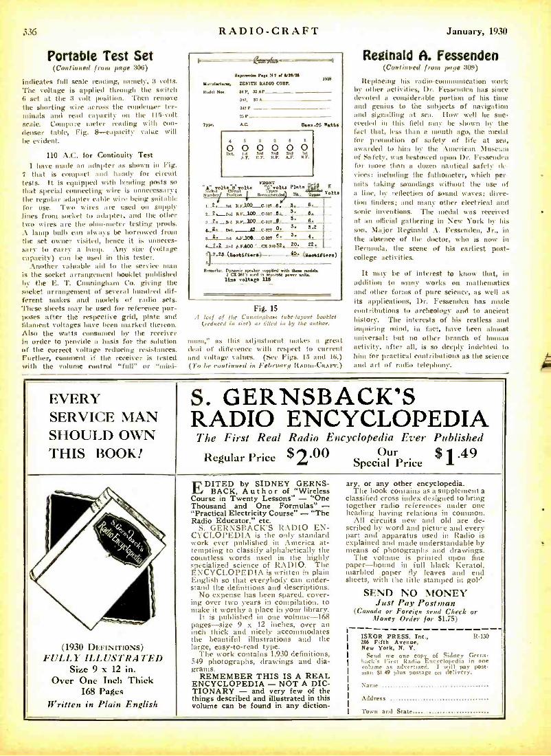
Portable Test Set (Continued from page :306)
indicates full scale reading, namely, 3 volts. The voltage is applied through the switch /i set at the 3 volt position. Then remove the shorting wire across the condenser ter- minals and read capacity on the 115 -volt scale. Compare meter reading with con- denser table, Fig. 8- capacity value will be evident.
110 A.C. for Continuity Test I have made an adapter as shown in Fig.
î that is compact and handy for circuit tests. It is equipped with binding posts so that special connecting wire is unnecessary; the regular adapter cable wire being suit:d,i, for use. Two wires are used on supply lines from socket to adapter, and the other two wires are the ohm-meter testing prods. A lamp bulb can always be borrowed from the set owner visited, hence it is unneces- sary to carry a hump. Any size (voltage capacity) can be used in this tester.
Another valuable aid to the service man is the socket arrangement booklet published by the E. T. Cunningham Co. giving the socket arrangement of several hundred dif- ferent makes and models of radio sets. These sheets may be used for reference pur- poses after the respective grid, plate and filament voltages have been marked thereon. Also the watts consumed by the receiver in order to provide a basis for the solution of the correct voltage reducing resistances. Further, comment if the receiver is tested with the volume control "full" or "niini-
RADIO -CRAFT
R.4er.ede. P.s. N 1 at V1Ú26
Nanufaet.rw. ZENITH RADIO CORP.
Model Not 34 P. 36 AP
342. 37 A._ 342P
3' P
Tra. Uses -96 Watts
6 3 3 Y 6 I
0 0 0 0 0 0
FRONT
Wad t r,Lì olts 31t6 Plate Number PoMtbn Recommended W.
R
Volta
,._2.- Iet R.F.100___ C3n_6. - A. - 6_. 2._ 2._ ßW 6' _ 6. 3. _3rd R.R.__100_c4r7 __s'
_ E.-
4..2...- Dd. _.!2_-cur 0 S._ sg s_2-Iñ A.R.306-_c321_e_ S_4_ 4.-T.2__2,d A.F100'-_cx-3Io6S. 20.
+-7.2.5-(a«tsaers)------os-lssssa.F.) IJ
Remarks: Dynamic PuR supplied sodas. 2 C7-3n'.ä It wpm.% l.vn a.ttt
lime voltage 116
Fig. 15 .1 leaf of the Cunningham tube -layout booklet
(reduced in size3 as tilled in by the author.
mum." as this adjustment makes at great dead of difference with respect to current and voltage values. (See Figs. 15 and 16.) (7'o he continued in February ltAmo- CR Arr. )
January, 1930
Reginald A. Fessenden (Coitioued front page 304)
Replacing his radio-communication work by other activities, Dr. Fessenden has since devoted a considerable portion of his time and genius to the subjects of navigation and signalling at sea. How well he suc- ceeded ill this field ntay he shown by the fact that, less than a mouth ago, the medal for promotion of safety of life at scat, awarded to him by the American Museum of Safety, was bestowed upon Dr. Fessenden for more than a dozen nautical safety dc. vices: including the fathonteter, which per nuits taking soundings without the use of a line, by reflection of sound waves; direc- tion finders; and many other electrical and sonic inventions. The medal was received at an official gathering in New York by his son, Major Reginald A. Fessenden, Jr., in the absence of the doctor, who is now in Bermuda, the scene of his earliest post - college activities.
It may be of interest to know that, in addition to utanv works on mathematics anti other fumes of pure science, as well as its applications, Dr. Fessenden has made contributions to archeology and to ancient history. The interests of his restless and inquiring mind, in fact, have been almost universal; but no other branch of human activity, after all, is so deeply indebted to him for practical contributions as the science and art of radio telephony.
EVERY SERVICE MAN SHOULD OWN THIS BOOK!
S. GERNSBACK'S RADIO ENCYCLOPEDIA
7710 First Real Radio Encyclopedia Ever Published
Regular Price .00 Our $ 1.49 2 Special Price
- o r \ r y s'
1); ,
(1930 DEFINITIONS) FULLY ILLUSTRATED
Size 9 x 12 in. Over One Inch Thick
168 Pages Written in Plain English
EDITED by SIDNEY GERNS- BACK, A u t h o r of "Wireless
Course in Twenty Lessons" - "One Thousand and One Formulas" - 1ePractical Electricity Course" - "The Radio Educator," etc.
GERNSBACK'S RADIO EN- CYCLOPEDIA is the only standard work ever published in America at- tempting to classify alphabetically the countless words used in the highly specialized science of RADIO. The ENCYCLOPEDIA is written in plain English so that everybody can under- stand the definitions and descriptions.
No expense has been spared, cover- ing over two years in compilation, to make it worthy a place in your library.
It is published in one volume -168 pages -size 9 x 12 inches, over an inch thick and nicely accommodates the beautiful illustrations and flue
g easy -to -read type. large, The work contains 1.930 definitions,
549 photographs, drawings and dia- grams.
REMEMBER THIS IS A REAL ENCYCLOPEDIA - NOT A DIC- TIONARY - and very few of the things described and illustrated in this volume can be found in any diction -
together
scribed
explained
sheets,
I
ary, or any other encyclopedia. The book contains as a supplement a
classified cross index designed to bring radio references under one
heading having relations in common. All circuits new and old are de-
by word and picture and every part and apparatus used in Radio is
and made understandable by means of photographs and drawings.
The volume is printed upon fine paper -bound in full black Keratol. marbled paper fly leaves and end
with the title stamped in gol"
SEND NO MONEY Just Pay Postman
(Canada or Foreign send Check or Money Order for E1.75)
- ISE'OR PRESS, Inc., R -130 286 Fifth Avenue, New York, N. Y.
Send me one copy of Sidney Gerns- hack's First Radin Fncvclola dim in one volume as advertised. I will pay post - mall $1.49 plus postage on delivery.
;'same
Address
Town and State
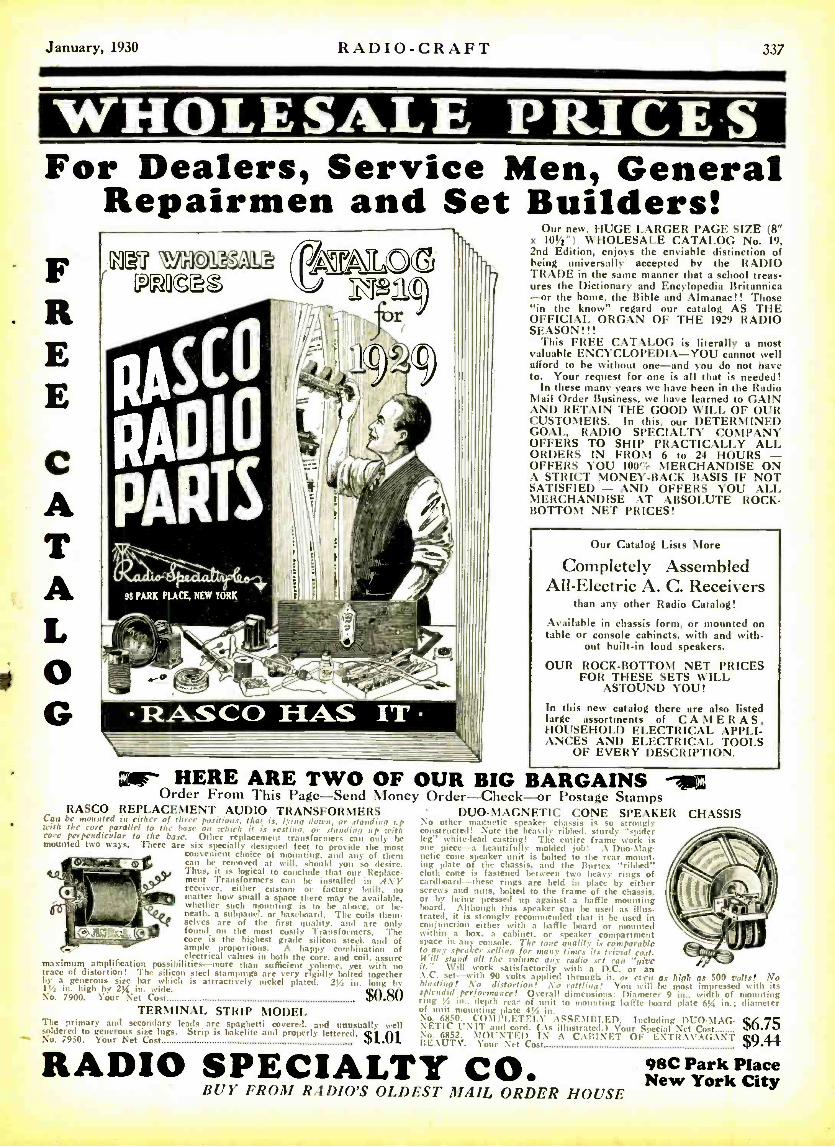
January, 1930 RADIO -CRAFT ,137
WHOLESALE PRICE For Dealers, Service Men, General
Repairmen and Set Builders! F R E E
C A T A L o G
L
ÍtCú WHO ESAL e e PG°30tGt
j II p.
'
OS Lo .
RAO I
I !`, .'r.Tn . %
98 PARK PLACE, NEW YOR
_. [ \
ILK - (11:t9 /
-- - r\c - _- +i
.. ' G/
ilS2,9
t,
4
f
-r
r r'
f.- . , >)
fJ tr
_
aeC-1-.- %' ¡ .i - -
RASCO HAS IT
Our new, HUGE LARGER PAGE SIZE (8 x 101/= ") WHOLESALE CATALOG No. 19, 2nd Edition, enjoys the enviable distinction of being universally accepted by the RADIO TRADE in the same manner that a school treas- ures the Dictionary and Encylopedia Britannica -or the home, the Bible and Almanac!! Those "in the know" regard our catalog AS THE OFFICIAL ORGAN OF THE 1929 RADIO SEASON!!!
This FREE CATALOG is literally a most valuable ENCYCLOPEDIA -YOU cannot well afford to be without one -and you do not have to. Your request for one is all that is needed!
In these many years we have been in the Radio Mail Order Business, we have learned to GAIN AND RETAIN THE GOOD WILL OF OUR CUSTOMERS. In this, our DETERMINED GOAL, RADIO SPECIALTY COMPANY OFFERS TO SHIP PRACTICALLY ALL ORDERS IN FROM 6 to 24 HOURS - OFFERS YOU 100' MERCHANDISE ON A STRICT MONEY -BACK BASIS IF NOT SATISFIED - AND OFFERS YOU ALL MERCHANDISE AT ABSOLUTE ROCK - BOTTOM NET PRICES!
Our Catalog Lists More
Completely Assembled All- Electric A. C. Receivers
than any other Radio Catalog!
Available in chassis form, or mounted on table or console cabinets, with and with.
out built -in loud speakers.
OUR ROCK -BOTTOM NET PRICES FOR THESE SETS WILL
ASTOUND YOU!
In this new catalog there are also listed large assortments of CAMERAS, HOUSEHOLD ELECTRICAL APPLI- ANCES AND ELECTRICAL TOOLS
OF EVERY DESCRIPTION.
gir HERE ARE TWO OF OUR BIG BARGAINS -ijsc Order From This Page -Send Money Order -Check -or Postage Stamps
RASCO REPLACEMENT AUDIO TRANSFORMERS Can be mounted in either of three positions, that is, lying dtnrn, or standing t. with the core parallel to the hase on tehir!, it is resting or standing up with core perpendicular to the base. Other replacement transformers can only he mounted two ways. There are six specially designed feet to provide the most
convenient choice of mounting, and any of them can be removed at will. should you so desire. Thus, it is logical to conclude that our Replace- ment Transformers can be installed in :LYE receiver, either custom or factory built, no matter how small a space there may ae available, whether such mounting is to he above. or be- neath. a subpanel, or baseboard. The coils them- selves are of the first quality, and are only found on the most costly Transformers. 'l'he core is the highest grade silicon steel, and of ample proportions. A happy combination of electrical values in both the core. and coil, assure maximum amplification possi'tilities -more than sufficient ,volume yet with no trace of distortion! The silicon steel stampings are very rigidly bolted together
by a generous size bar which is attractively nickel plated. 2Y., in. long by 11/4 in. high by 2% in. wide.
Soso No. 7900. Your Net Cost .Vpt111
TERMINAL STRIP MODEL The primary and secondary leads are spaghetti covered, and unusually well soldered to generous size lugs. Strip is Bakelite and properly lettered, $1.01 No. 7950. Tour Net Cost
DUO -MAGNETIC CONE SPEAKER No other magnetic speaker chassis is so strongly constructed! Note the heavily ribbed, sturdy "spider leg" white -lead casting! The entire frame work is one piece -a beautifully molded job; .\ Duo-Mag- netic cone speaker unit is bolted to the rear mount- ing plate of the chassis, and the Burtex "ribbed" cloth cone is fastened between two heavy rings of cardboard -these rings are held in place by either screws and nuts, bolted to the frame of the chassis, or by being pressed up against a bathe mounting board. Although this speaker can be used as illus- trated, it is strongly recommended that it be used in conjunction either with a bale hoard or mounted within a box, a cabinet. or speaker compartment space in any console. The tone quality is comparable to any speaker selling for ma my times its trivial cost. 11'ill stand all the Volume any radio set can "give it." Will work satisfactorily' with a D.C. or an A.C. set -with 90 volts applied through it. or even as high as 500 molts! No blasting! No distortion! No rattling! You will he most impressed with its splendid performance! Overall dimensions: Diameter 9 in., width of mounting ring !6 in., depth rear of 't to mounting baffle board plate 6% in.; diameter f unit mounting plate 41 in.
No. 6850. COMPLETELY ASSEMBLED. including DUO -MAG- $6.75 N ETIC UNIT and cord. (.\s illustrated.) Your Special Net Cost v+ No. 6852. MOUNTED IN .\ CABINET OF EXTR. \\'.V;.\NT $944 I:F.. \UT '. Your Net Cost `p
CHASSIS
RADIO SPECIALTY CO. 98C Park Place New York City BUY FROM RADIO'S OLDEST MAIL ORDER HOUSE
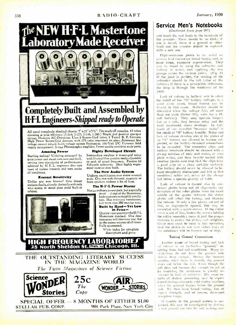
338 RADIO -CRAFT
Ihe L aboEatoryMade Kecelver
Completely Built and Assembled by 11 F-L Engineers -Shipped ready to Operate
All metal completely shielded chassis: 7 "x21 "x7tí " Fits nearly all consoles. 11 tubes operating at peak efficiency [5-224; 3 -227; 2.245; 1 -280.] Single dial positive one -spot tuning; Humless AC Operation; Uses 5 Screen -Grid tubes, 5 Tuned R. F. Circuits; High Power Screen -Grid detector, with 175 volts impressed on plate; Automatic line voltage control inbuilt holds voltage against fluctuating; 100 -Volt DC Dynamic field
supply incorporated; 3 stage Phonographic amplifier, Finest quality precision made parts.
Amazing Power Highly Developed Circuit Intermediate employs 4 screen -grid tubes with 5 tuned filter circuits, easily adjustable to peak of tuned frequency. Positive 10 Kilocycle selectivity. Most highly engin- eered receiver ever built.
The New Audio System Uniform amplification over entire musical scale. Operates with dynamic, magnetic or horn speakers without a bit of hum.
Startling realism! Unfailing accuracy! Its great power and sweet tone awe and thrill, setting new standards of performance achieved by H. F. L. engineers after two years of tireless research and tests under all conditions.
Keenest Sensitivity Unlike any ever known! Gets distant stations clearly, sharply, distinctly with only wire screen or metal plate aerial built in cabinet.
The H -r -L Power Master Not art ordinary power pack, but a specially
devel- d unit of the Mastertone, built separately to simplify installa- tion. Has oversized transformer, full wave type 280 rectifier tube. Built by Hand -Yet Low
in Price - Quality-not quantity -theH -F -L Mastertone standard. One dem- onstration will convince you that its the master receiver of all times. Fully guaranteed.
V /rite today for complete description and price.
HIGH FREQUENCY IABORATORIEf 28 North Sheldon St. Chicago, Ill.
THE OUTSTANDING LITERARY SUCCESS IN THE MAGAZINE WORLD
The Twin Magazines of
Science
WO Stories
25c The
Copy
Science Fiction
SPECIAL OFFER - 8 MONTHS OF EITHER R $1.00 STELLAR PUB. CORP. 98R Park Place, New York City
January, 1930
SerVlce Men's Notebooks (Continued front. page 297)
and touch the test leads to the terminals of the arrestor. There should be no click; if one is heard, there is a ground or t tl'r fault and the arrestor should be replaced with a new one.
High-resistance ,joints in an aerial or ground lead ontuurage broad tuning and, in
some cases, excessive regeneration. They may he found by using the voltmeter tint h;attcry in series, and applying Ile test !songs across the various joint s. (Fig. 2) If the ,joint is perfect, the reading of the tolttuetcr should be the ftdl cadre of the battery; if there is a perceptible difference, the drop is through the resistance of the .joint.
Lack of vuhnn in battery sets is often the result of loco "1I" battery voltage; in a good litany eases, broad tuning can be traced to this valise. Batteries should be discarded when the voltage falls oti more than one sixth (blow 371/.. volts for a 4:r-
volt battery). They rung operate longer; but as a rule, they become noisy and the fault mentioned above develops. In fact. much of our so- called "summer static" is the result of "It" battery trouble. Noise and lack of vol (Iccclop also if the plates of an ".1" battery are allowed to hceou' sul- phated, or the battery -terminal con elt tItins to he corroded. The connector clips :nut battery terminals should be cleaned with a
string solution of soda and wader, or et cu
plain water, and then heavily coasted with vaseline (make sure first that the clips have it good grip on a clean metallic ,surface). l'ho battery should never be allowed tit be- come completely discharged and left in that condition; better yet, never let the charge fill below a specific gravity of 1.200.
Lack of volume is caused also by con- denser plates being out of alignment; any deviation of the rotor plates front the exact middle of the spaces between the stator plates will affect the tuning, and likewise the volume. If only a few plates :tre out of line, or improperly spaced, titis may be corrected with a screw-driver. If the entire rotor is out of line, loosen the strews holding the entire assembly prove it just the proper distance to center the plates, and retigltlen. Great care must be used ill this optratiou, Ilnit the plates do not turn either way; or the condenser will be titrowu out of step.
Testing Ground Connections
.1nother cause of Inroad Inning and lack of volume is an ineticclive "ground," re- sulting from had soil conditions. \l:tny in- -t allalions do out have the ground rods driti n deep enough. During the summer months. when there is droulli. the ground tbii -s out below the roil. i. vii though the soil clues not become dry enough to act as an insulator, the resistance is greatly in-
vreascd he tack of moisture. 'the sau' re- sults of shallow grounding may he exper- ienced during extremely cold winter weather, \then the ground freezes below the ground rod. We then have broad tuning, loss of shoal strength, and of course, decreased reception range.
If trouble iu the ground system is sus- pected, this may be investigated by driving t test ground ¡titi into IIu soil, mucking sure
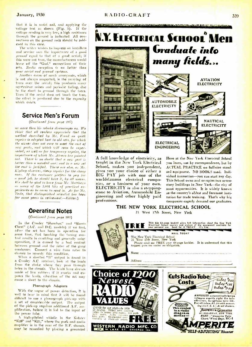
January, 1930 RADIO- CRAFT 339
that it is in moist soil, and applying the Voltage test as shown (Fig. 3). If the voltage reading is very low, a high resistance through the ground is indicated. All con- nections on the ground rods should be sold- ered in this case.
The writer wkhes to impress on installers and service men the importance of a good ground equal to that of a good aerial; if this were not true, the manufacturers would leave off the "Gild." connections of their sets. Radio rereplion is no better than your aerial and ground . gxtems.
Another cause of much annoyance, which is not always suspected, is the swaying of trees over the aerial; this produces many mysterious noises and periodic fading, due to the short to ground through the trees. Even if the aerial does not touch the tree, the effect i. produced due to the capacity Which cxiI
Service Men's Forum (Continued from page 297)
os more than his rebuke discourages ax. Il-e Viii I, that all readers appreciate that the method described by Mr. Freed On quirk repairs is adapted best to old sets, for Ichirh the owner does not care to meet the roast of new prn'lx, and which will 80011 be super- seded; ax well as for temporary repairs, the importance of which Mr. Alcorn has p,intr,t onl. There is no doubt that a new part is better than a mended one: and in a new s,J the cost ix .justified. 7'bere are also, as M,'. /Kipling observes, cheap repairs for the rheas ones. If the customer prefers to pall for a good job, he should have it, by all means. ll'e shall be glad to bare from Mr..11olfhews as many of the 1,1101 bits of practical ex- periences as he cares to send in. As for Mr. Texts, that distinguished .scientist has been for some fears in retirement.- Editor.)
Operating Notes (Continued from page 3113)
In the Crosley "Showbox' and "Show - Chest" (A.C. and D.C. model..) if Nye find, after the set has been in operation for some time, that touching the tuning con- trol results in crackling and generally noisy Operation, it is caused by a bad contact between ground and the rotor of the gang condenser. Connect a wire from rotor to chassis to remedy this condition.
When a .sharlcd "Il" output is found in a Crosley A.C. receiver, look at the leads from the choke where they pass through holes in the chassis. The leads halve sleeve, stade of live rubber; if it cracks and ex- poses the leads, vibration of the set may cause a short to the chassis.
Phonograph Adapters With the vogue of power detection, it i.
well to bear in mind that it Will be found difficult to use a phonograph pick -up with a set of considerable output. The output of the pick -up requires additional A.F. am- plification, before it is led to the input of the power tube.
A high -pitched whistle in the Kolster "K20" and "K21," where the pack and midi. amplifier is in the rear of the R.F. chassis, may be remedied by placing a grounded j
-^r
lILY. muumuu Scnooi Men Graduate info many fields...
AVIATION ELECTRICITY
NAUTICAL ELECTRICITY
ELECTRICAL ENGINEERING
A full knowledge of electricity, as taught in the New York Electrical School, makes you independent, gives you your choice of either a BIG PAY job with one of the world -famous electrical compa- nies, or a business of your own. ELECTRICITY is also a stepping- stone to Aviation, Automobile En- gineering and other highly paid professions.
Here at the New York Electrical School you learn, not by correspondence, but by ACTUAL PRACTICE on full -size stand- ard equipment. NO BOOKS used. Indi- vidual instruction -you can start any day. This School owns and occupies two seven - story buildings in New York -the city of most opportunities. It is widely known as the country's oldest and foremost insti- tution for trade training. That's why big companies eagerly demand our graduates.
THE NEW YORK ELECTRICAL SCHOOL 21 West 17th Street, New York
Thls bIg 64paae booklet giver full Inlermation bout the New York Electrical School courser and picture f the equipment available for
your personal use seed for it TO DAY. It's free.
MAIL TODAY The New York Ele,trical School 21 Vest 17th Street, New York
Please send me FREE your 64 -page booklet. It is understood that this request puts me under no obligation.
Name
Address
c cxI) for sir wholes:le 19 7.1
salues in gscreenllggildsvradl,..1... Iii puh 01,11 :nulle. radin kits, parts. Guaranteed , I.u.li at uhuiraalc prices.
WESTERN RADIO MFG. CO. I w. LAKE ST. CHICAGO ILL.
!Cuts RadioTube _- Costs
/
AMPERITE automatically keep voltages exactly right for tube e1R,-irncv. Lengthens tube life. For all tubes. 81 l a with mount -
`
na (in I ..5. A. ) At all dealer.. This symbol 4 AM radio !r^ PERITB ó ratlos diagram 661 BROADWAY. NEW YORK means - FREE-- "Amperite Tuba
Chart. "Write Dept. RC -1
ERITE `SELF ADJUsTIxG- Rh,artor
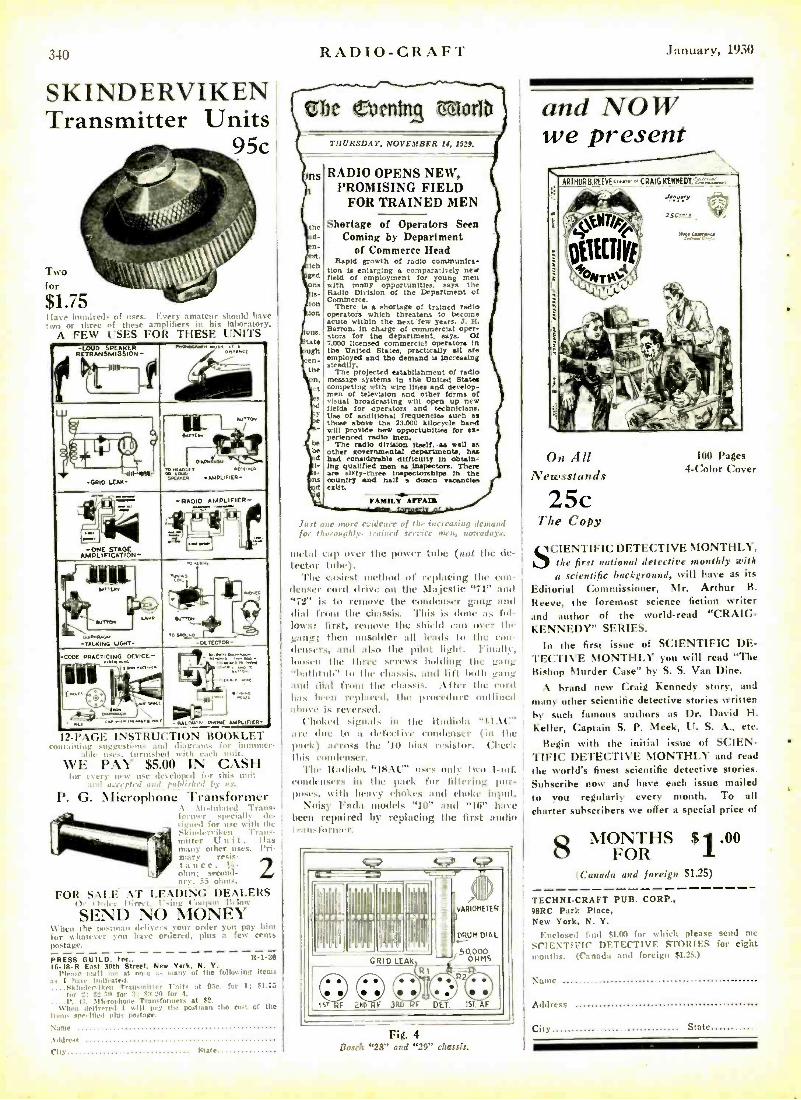
SKINDERVIKEN Transmitter Units
95c
Two for
$1.75 ds of uses. Every amateur should have
of these amplifiers in his laboratory. t I I \ USES FOR THESE UNITS
-WOG WEARER RETRANSMISSION..
rrwsw- F/ra .
-MO LUX-
-ONE STAGE AMPLIFICATION-
-CODE PRACTICING 0EV,CC-
:..w.,.,...ar.. PS f -Nlsw.o weed ANeuncR-
12 -1' \ INSTkt-(; Fl(IN BOOKLET - - - for intlntller-
i -iu ! - Ti nuit. \VI-: l' :\l $5.00 IN CASH
11'< unit
l'. (;. \ het-of-Alone Transformer \ Undulated Traits - fol n -r specially de-
t1I frrr it,., with the - i . ,i.2.-r' ikeu Trans. /Hitter ('nit. Has moly other uses. Pri- mary resis- tance,
S ohm: secmpl- ary. 55 ohms.
FOR SALE AT LEADING DEALERS Or (trder I lirict, 1'-ing Coupon Below
SEND NO MONEY \Vhcu the pu -linan delivers your order you pay him for whatever lote have ordered, plus a few cents postage.
PRESS GUILD. Inc.. 1t -1 -30 16 -18 -R East 30th Street. New York, N. Y.
l'ira,' mail ale at on..e many of the follow in^ Items .1. I hase hull,- ate,l.
....Hkinden iken Tnursrn tiler i-nit: at Oc. for I; FI.T5
for tit 8'1311 for a; 1.2,1 for f. P. C. Si tiroitlone Trandornter. at $2.
\ \Ten delivered I will hay the poet man the not of the item: spe,dded plu,
Name
Addrers
City State
RADIO -CRAFT
THURSDAY, NOVEMBER 14, 1929.
ns RADIO OPENS NEW, PROMISING FIELD
FOR TRAINED MEN
Shortage of Operators Seen d- Coming by Department
ee of Commerce Head
den Rapid growth of radio tommvnica-
g Lion Is enlarging comparatively n field of employment for young men
on. with many opportunities, aa)a the y- Radio Division of the Department of
ion Commerce. There is a shortage of trained radio
ion operators which threatens to become acute within the next few years, J. H.
om Barton, in charge of commercial oper- ta .
atom for the department. says. Cat 7,000 licensed commercial operators in
ugh the tinned Stated. practicay alt are en- employed and the demand la increasing
steadily. the The projected establishment of radio n, measage systems In the tinned States ct competing with wire lines and develop -
men of television and other forms of s Visual broadcasting will open up new
W fields for operators and technicians. , Use of additional frequencies such as e those above the 73.000 kilocycle band - will provide new opportunities for es.
perlenced radio men. be The radio division Itself. as wen /a be other governmental department.. has d had considerable difficulty in obt.tn- I' Mg qualified men all Inspectors. There
are ISty-tlres lnepectorsbtps in the n couhtry and half a dorm fancies d CRUt,
FAMILY ARAR
Just I tee morve eririeil, of tiri' increasing demand for ti urnundly- trained service mru, nenvadays.
nulnl .ap over the power tube (not the de- tector t
easiest method of replacing the eon - dcustr turd drive on the Majestic "71" and '72 is to remove the comltnser gang and dial from the chassis. 'l'Iris iv donc as fol- lows: first. remove the shield ran over titi' gant; then unsolder all leads to the con- densers. and also the pilot light. hinallc, loosen the three sereins holding the g:rlg h :ithtuli' lu the rit :I..is, and lift both gam: and dial front the chassis. .\ftir (he nord has been replaced. the procedure outlined above is reversed.
Choked signals in the ltndinla "11. \l "' are abri, to a dcfeetiwe rundrnser (in the amok) nerds the '10 bias resistor. ('.heel: this condenser.
The Ifndioln '18:\('" uses only two 1 -utf. rondeu.,rs in the pack for filtering pur- pose.. with henv 0ml:es nn(1 choke input.
Noisy 1 °naira models "I(i" and "Ili" have been repaired by replacing the first :Wolin I i nu.fnruier.
°---= ;
VARIOMETER I
DRUM DIAL
S°4 Iilgllhg
I
I
''
"" I Ng,
= _ i
GRID LEAN 50.000
OHMS
® ® ® : IsT F END F .3RD F DET. ISTi F
Fig. 4 Bosch "28" and "29" chassis.
January, 1930
and NOW we present
ARTHURB.REEVEr,''CRAIGKEINEDI.
dff-"I
2sr..r..e r.
On All Newsstands
25c The Copy
100 Pages 4 -Color Cover
'I CIENTIFIC DETECTIVE MONTHLY, the first national detective monthly with a scientific background, will have as its
Editorial Commissioner, Mr. Arthur R.
Reeve, the foremost science fiction writer and author of the world -read "CRAIG- KENNEDY" SERIES.
In the first issue of SCIENTIFIC DE- TECTIVE MONTHLY you will read "The Bishop Murder Case" by S. S. Van Dine.
A brand new Craig Kennedy story, and
many other scientific detective stories written by such famous authors as Dr. David H. Keller, Captain S. P. Meek, U. S. A., etc.
Begin with the initial issue of SCIEN. TIFIC DETECTIVE MONTHLY and read the world's finest scientific detective stories.
Subscribe now and have each issue mailed
to you regularly every month. To all charter subscribers we offer a special price of
E; MONTHS $1.00
(Canada and foreign $1.25)
TECHNI -CRAFT PUB. CORP., D8RC Park Place, New York, N. Y.
Enclosed lind $1.(10 for wit ich please send nie
SCIENTIFIC DETECTIVE STORIES for eight mmmths. (Canada and foreign $1.25.)
Name
Address
City State
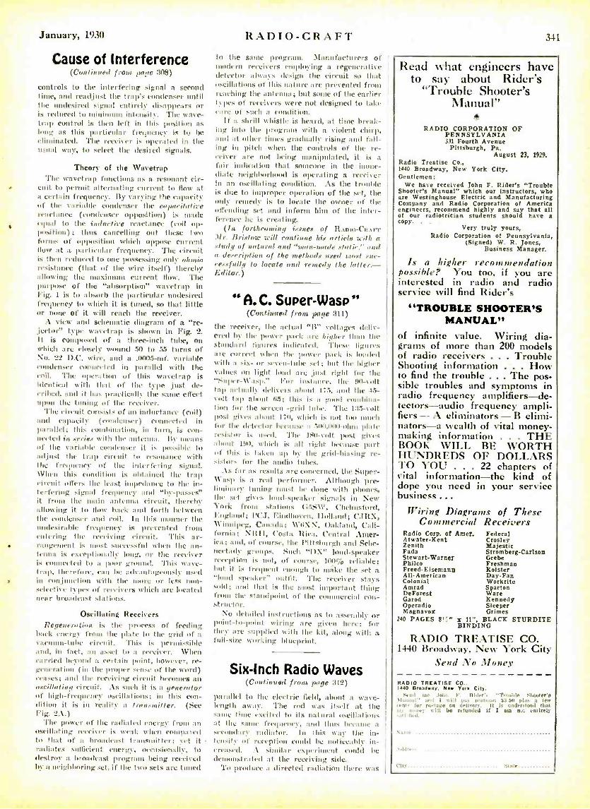
January, 1930 RADIO -CRAFT 3.11
Cause of Interference (Continued from ¡cage 308)
controls to the interfering signal a second time, and readjust the trap's condenser until the undesired signal entirely disappears or is reduced to minimum intensity. The wave- trap control is then left in this position as long as this particular frequency is to be eliminated. The receiver is operated in the usual wary, to select the desired signals.
Theory of the Wavetrep The wavetrep functions as a resonant cir-
cuit to permit alternating current to flow- at a certain frequency. By varying the capacity of the variable condenser the capacifofire reactance (condenser opposition) is made equal to the inductive reactance (coil op- position); thus cancelling out these two forms of opposition which oppose current flow at a particular frequency. The circuit k then reduced to one possessing only olunie resistance (that of the wire itself) thereby allowing the maximum current flow. The purpose of the "allsorpthIn" wavetrap in Fig. 1 is to absorb the particular undesired frequency to which it is tuned, so that little or none of it will reach the receiver.
A view and schematic diagram of a "re- jector" type wanetrap is shown in Fig. 2. It is c posed of a three -inch tube, on which are closely wound 50 to 55 turns of No. 22 D.C. wire, and a .0005 -mf. variable condenser connected in parallel with the coil. The operation of this vvavetrap is identical yvitIi that of the type ,just de- (Tilted. and it has practically the same effect upon the tuning of the receiver.
The circuit consists of an inductance (coil) and capacity ( condenser) connected in parallel; this cumhin:etiou, in turn, is con- nected in .series with the antenna. liy means of the variable condenser it is possible to adjust the trap circuit to resonance with the frequency of the interfering signal. \Chen this condition is obtained the trap circuit offers the least impedance to the in- terfering signal frequency and "by- passes" it from the train antenna circuit, thereby allowing it to flow hack and forth between. the evmulensel- and coil. Ili this manner the undesirable frequency is prevented from entering the receiving circuit. This ar- rangement is moist successful when the an- tenna is excepli.iiially long, or the receiver is el nnccly(1 to a poor ground. This wave - trap, therefore, can be advantageously used in ronjunctiou with the more or less non - seleetive types of receivers which are located near broadcast stations.
Oscillating Receivers Regeueraf;OR is the process of feeding
hack energy from the plate to the grid of a vacuum-tube circuit. This is permissible and, in fact, an asset to a receiver. When carried beyond a certain paint, however, re- generatiun t in the proper sense of the word) ceases; and the receiving circuit becomes an axcillating circuit. : \s such it is a generator of high- frequency usciIl:ttionS; in this con- dition it is in reality a fran.su:ilfer. (See Fig. 2:\.)
The power of the radiated energy front an oscillating recriver is weak when compared to that of :t broadcast transmitter; vet it radiates sufficient energy, occasinnutliv, to destroy a broadcast program being received by a neighboring set, if the two sets are tuned
to the same programs. Manufacturers of modern receivers employing a regenerative detector always design the c'irc'uit so that useillaIiiuns of this nature are prevented from reaching the antenna; but some of the earlier types of receivers were not designed to take e:ne of such a condition.
If a shrill whistle is heard, at time break- ing into the program with a violent chirp, and at other times gradually rising and fall- ing in pitch when the controls of the re- ceiver are not being manipulated, it is a
fair indication that someone in the imme- diate neighborhood is operating a receiver in an oscillating condition. As the trituhle is clue to improper operation of the set, the only remedy is to locate the owner of the i ffrnding set and inform him of the inter- ference he is creating.
(In forthcoming issues of Ramo-Ca .trr .)!r. Bristow will continue his article with e study of natural and "man -made static.- and a description of the methods used most nae- cessfullg to locate and remedy the hotter. - Editor.)
"A.C. Super -Wasp (Continued fram ¡rage 311)
the receiver, the actual "B" voltages deliv- ered by the power pack are higher than the standard ligures indicated. These ligures are correct %Own the power pack is loaded with a six- or seven -tube set; but the higher values on light load are just right for the "Super -Wasp." l'or instance, the 941 -volt tap actually delivers ::bout 1 15, and the 45- volt tap about 1i5; this is a good combina- tion for the screen -grid tube. The 135-volt post gives about 1 ;11, which is not ton much for the detector because a 500,0X141 -ohnt plate resistor i. used. The lso -,-alt post gis is about uts:, which is all right because part of this is taken up In the grid -biasing re- sistor. fur the audio tubes.
\, tarais results are concerned, the Super - \Cn.l' is n read performer. Although pre- liminary tuning must be done with phones, the .set gives land -.speaker signals in New York front stations (i55 \l ", Chelmsford, England; l'('J, Eindhooven, IIolluind; C1IIX, \Cinnipcg, (7anada; \C4iNoN, Oakland, Cali- fornia; N1111. ('usta Rica. Central :\mer - ica; :nul, of course, the Pittsburgh and Sche- tiretaily groups. Such "1)X" loud- speaker reception is not, of cousu., 100¡ reliable; but it is frequent enough to m:íkc the set a "tonal speaker" (outfit. 'rite receiver stays sold; nad that is the must important thing from the standpoint of the cunu11ereial con- structor.
No detailed iulstructittlls as to assembly or point -tu -point wiring are given here; for they are supplied with the kit, along with a full -size working blueprint.
Six -Inch Radio Waves (C'onlinned from page 312)
parallel to the electric field, uhout a wave- length away. The rod was itself at the saute time excited to its natural oscillations al the 5:11114 frequency, and lies became a secondary- radiator. In this way the in- tensity of re'ceplion could he not ireahie in- creased. .\ similar experiment could be deuunistrutted ut t the receiving side.
To product. a directed radiation there was
Read what engineers have to say about Rider's
"Trouble Shooter's Manual"
a
RADIO CORPORATION OF PENNSYLVANIA 331 Fourth Avenue
Pittsburgh, Pa. August 23, 1929.
Radio Treatise Co., 1440 Broadway, New York City. Gentlemen:
We have received John F. Rider's "Trouble Shooter's Manual" which our instructors, who Are Westinghouse Electric and Manufacturing Company and Radio Corporation of America engineers, recommend highly and say that all of our radiotrician students should have a copy. .
Very truly yours, Radio Corporation of Pennsylvania,
(Signed) W. R. Jones, Business Manager.
Is a higher recommendation possible? You too, if you are interested in radio and radio service Is ill find Rider's
"TROUBLE SHOOTER'S MANUAL"
of infinite value. Wiring dia- grams of more than 200 models of radio receivers ... Trouble Shooting information How to find the trouble ... The pos- sible troubles and symptoms in radio frequency amplifiers -de- tectors -audio frequency ampli- fiers -A eliminators -B elimi- nators-a wealth of vital money- making information . THE BOOK WILL BE WORTH HUNDREDS OF DOLLARS TO YOU . 22 chapters of vital information -the kind of dope you need in your service business ...
Wiring Diagrams of These Commercial Receivers
Radio Corp. of Amer. Federal Atwater -Kent Crosley Zenith Majestic Fada Stromberg- Carlson Stewart -Warner Grebe Philco Freshman Freed- Eisemanit Kolster All -American Day -Fan Colonial Workrite Amrad Sparton DeForest Ware Garod Kennedy Operadio Sleeper Magnavox Grimes
240 PAGES 8'S" x 11 ", BLACK STTIRDITE BINDING
RADIO TREATISE CO. 1.10 Broadway, New York City
Send No .Money
RADIO TREATISE CO.. 1440 Broadway. New York City.
Send me .loin F. lti ler' 'T"..,I ie Sload er's ua,. ue ant I ,.m pay load man $3.e0 nais are ,end+ tar teetare on deli,ery. It Is unlertond that
mane]. n 111 bo refunded it 1 am suc entirely ,J I, iiil.
cat, Stet,
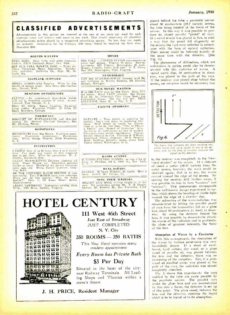
342 RADIO -CRAFT
CLASSIFIED ADVERTISEMENTS Advertisements in this section are inserted at the cost of ten cents per word for each
insertion -name and address each count as one word. ('ash should accompany all classified advertisements unless placed by a recognized advertising agency. No less than ten words are accepted. Advertising for the February 1930 issue, should be received not later than
December 10th.
AGENTS WANTED
FREE BOOK. Start little mail order business. lladwil, 27A -74 Cortlandt Street, New York. GET OUR FREE SAMPLE CASE - Toilet Ar- ticles, Flavorings, Soaps. Specialties. Wonder- fully profitable. LaDerma Co., Dept. SC, St. Louis, Mo.
AIRPLANE SUPPLIES
MODEL AEROPLANE Supplies. Write for free bundle of sample stock. Aero Shup, 3050 Hurlbut Ave., Detroit, Mich.
BUSINESS OPPORTUNITY
CAPITAL -An experienced dependable broker will aid in financing projects of merit. Amster Leonard, East Orange, N. J. SELL BY MAIL. Books, Novelties, Bargains! Large profits. Particular FREE! I). Elfco, 521 South Dearborn, Chicago.
CHEMICALS BOOKLET OF EXPERIMENTS and chemical catalog. 15e. General Chemical Company, Box 397, Reading, Penna.
DETECTIVES
DETECTIVES Earn Big Money. Excellent oppor- tunity. Experience unnecessary. Particulars Free. Write, George Wagner, 21908 Broadway, N. Y.
INSTRUCTION
JIONEY
FOR SALE - UNITED STATES commemorative silver half dollars. Pilgrim, 90 cents. Monroe, Lexington, 1921 Pilgrim. Bennington, $1 each. Oregon, Lincoln, Grant, $1.25 each. G. T. Davis, Box 1791, Huntington, West Virginia.
NUMEROLOGY FUR 1930 NUMEROLOGICAL forecast send 7.0. and birthdate to Martha Sanchez, 824 IIoward, Detroit, Michigan.
OLD MONEY WANTED $5 to $500 EACH paid for Old Coins. Keep ALI. old money. Many VERY valuable. Get Posted. Send 10c. for illustrated Coin Value Book, 4x6. Guaranteed Prices. We buy and sell. COIN EXCHANGE, Room 10. I.e Roy, N. Y.
PATENT ATTORNEY
PATENTS - Time counts in applying for ptents. Don't risk delay in protecting your ideas. Send sketch of model for instruc- tions or write for free book, "flow to Obtain a Patent" and "Record of Invention" form. No charge for information on how to proceed. Communications strictly confidential. Prompt, careful, efficient service. Clarence A. O'Brien, Registered latent Attorney. 343 -A Security Bank Building (directly across street from Patent Office), Washington, D. C.
I CATCH from 45 to 50 foxes from 4 to 5 weeks' time. Can teach any reader of this magazine how to get them. Write for particulars. W. A. RADIO STAMPS !!alley,_ Stanstead Oue. - - -
LEARN MARBLEIZING Concrete ¡products all 15 1t:\Ütl) s'A'IIt1N STAMPS. uo two alike $1.
kind. \Void, Metals. etc. Resembles polished Chas. A. I'hildius, 510 E. 120th St., New York,
marble or onyx. Wonderful for garden furniture, N. \'
table tops, etc. Write, Cowell Institute, Gray- ling. Mich. BE THE LICENSED RADIO DOCTñR of your community. Earn $7.00 -$10.00 spare time evenings. Write now for free booklet, "Why the Radio Doctor ?" Dept. C. 131 Essex Street, Salem, Massachusetts.
REAL ESTATE OZARKS. 40 Acres Missouri. $5 month. Own a hone. Jarrell. Mt. Vernon, Ill.
SONG POEM WRITERS POETRY AND SONG writing taught in 1? les -
LEARN TATTOOING. Instruction catalog, dime. . For particulars enclose IOc. R. D. Iliggin- Miller, X431 Main, Norfolk. Virginia. Iwthaum, 263 Bartlett St., San Francisco. Calif.
HOTEL CENTURY
EE .ir SC
if EE Ei
EEEEßtEfEç IEEE a_ WEE. ß6E9EG56E9
111 West 46th Street Just East of Broadway JUST COMPLETED
N. Y. City
350 ROOMS - 350 BATHS This New Hotel contains every
modern appointment
Every Room has Private Bath
$3 Per Day Situated in the heart of the city: near Railway Terminals. All Lead- ing Shops and Theatres within a
stone's throw.
J. H. PRICE, Resident Manager
January, 1930
placed behind the tube a parabolic mirror about 50 centimeters (19.7 inches) across, the tube being located at the focus of the mirror. In this way it was possible to pro- duce an almost parallel "pencil" of rays. If a metal screen was placed in this, in such a way that the pencil fell diagonally on the screen, the rays were reflected in accord- ance with the laws of optical reflection. '!'heir course could be followed exactly at the same time with the dctecttor. (See Fig. 3.)
The phenomena of diffraction, which are well -known in optics, could also be demon- strated with this radiation of waves. A round metal disc, 50 centimeters in diam- eter, was placed in the path of the rays. If the receiver was placed close behind this screen, no reception could be obtained; that
F'
F,g. 6. 17 L.daw line indicates the short coupling rod,
;, 6 iri ;could pick nt a signal in one of its sec-
tions; and. by the floe of current. transfer the signal to the detector.
is, the receiver was completely in the "elec- trical shadow" of the screen. . \t a distance of about it meter (39.37 inches) from the metal screen, however, the wave could be
received again; that is to say, the wines curved around the edge of the screen. By
moving the receiver still further away, it was possible to find in turn "maxima" and "minima "! This phenomenon corresponds to the well -known Arugu experiment in op- tics; which shows the bending of visible light around the edge of it circular disc.
'l'he refraction of the wave-radiation was demotistrated by letting the parallel pencil of rays from the transmitter fill on a glass lens about 30 centimeters (a fix)t) in diam- eter. By using the detector behind the lens, it was possible to demonstrate clearly the course of the radiation and in particular the plate of greatest intensity, the focus of the lens.
Absorption of Waves by a Conductor \ \.ilh this arrangement, the absorption of
the waves by various substances was very beautifully shown. If a sheet of card- board, hard rubber, dry wood, or a glass vessel of paraffin oil, was placed between the kris and the detector, there was no weakening of the reception. But, if a glass vessel of distilled water was placed in the path of the rays, the radiation was almost ( pletely absorbed.
Fig. I shows this experiment: the rays emitted by the tube are made parallel by the parabolic mirror. The parallel rays strike the glass lens and are concentrated by this into a focus; the detector is set up at this point. The glass vessel, between the lens and the detector, contains the liquid which is to be tested as to its absorption.
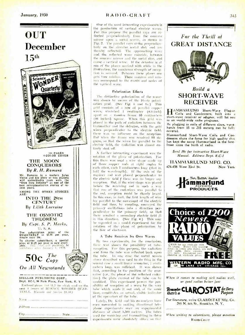
January, 1930
2:
OUT December 115"1
Sr
144 PAGES 4-COLOR COVER
THE MOON CONQUERORS By R. H. Romans
Mr. Romans is a modern Jules Verne and his story of two planets will undoubtedly rank with the "Shot Into Inanity" as one of the best interplanetarian stories of re- cent years.
AMONG THE OTHER STORIES ARE:
INTO THE 28TH CENTURY
By Lilith Lorraine
THE OSMOTIC THEOREM
By Capt, S. I'. Meeks, U. S. A.
The subscription price of the QUARTERLY is $1.75 per year, single copy 50c.
To charter subscribers, a special price of $1.25 per year is now avail- able rive/ v Fc
I. Ito 10.
5 The *-1 k, Copy
' A O.ViS84c
bvp,),g/l// t ,zt4 40,0. ' .4..,
On All Newsstands
STELLAR PUBLISHING CORP., Dept. RC-I, 98 Park Place, New York, N. Y.
Enelescd pit at, iti,1 $1.25 fer which send tne the next 4 issues of SCIENCE NVONDER QUAR- TERIX. (Ca (tad., it ((or1(1 $1.:4(t.)
Name
Address
City State
RADIO-CRAFT 343
One of the most interesting txIitmiulients is the podurtion ot vertical electric wa%es. For tlmis purposy Ihe parallel ras are re- fleeted perpendicularly front t In (.0I1C11% It
mirror upon a !octal sercen, ft, shown in Fig. 2. parallel rays strike perliemulicu- larly on the circular metal disk mold are therelw reflected. The approaching mate and the reflected wave coincide, between the emmeae mirror and 1114. metal disc, and cause a %ertical Wa VC. If the delector is at one of the pia CCs marked with white in the illustration, the maxi iiii strength of recep- tion is secured. Between these plaies one gets tone minima. l'hese maxima and mitin- i t111 correspond to the crests and nodes of the vertical wave.
Polarization Effects
The distinethe polarization of the NV.11%
this :damn by means of the Hertz polari- zation grid. (See Fig. I. and 4a.) This grid consists of a row of parallel copper %tires. stretched I centimeter (0.1-ilich) apart on a Nomomlen frame to cciitiiiii.iers ( Iii iuirlmis) stpiarc. When this grid was placed in the path of radiation lief %% Cell the transmitter and the detector, with the grid
:wires perpentlieuslerr io the elm.etric field, there \VaS iii) influence on the reception. But %%Alen the frame Will: revolved 90 de- gress, sit t hat the wires lav parallel to the electric field, the radiation. was a Ina ist en- tirely shut off.
.1 further interesting. experiment seas the rotation of the plant. of polarization. For this there was used ;t ivire shape made up of three copper nab: at right ;mmigles to cavil oilier, each 7 centimeters long. (that is, hall the walelength). If the axis of the receiver rod wtts placed perpendicular to the electric field f there was no longer any reeeption. But, if the wire shape SS :IS
bcOrl litt rt.t.t.il inf.; rod in sudi a way that one of the end-wires was parallel to the nod, reeeption could he clearly heard. In titis ease, in fact, the first length of wire lay parallel to the movement of tue electric Toil I :Old limits, by coupling, emot.Yed the prillla I'S OSViliatiOlIS bit° a direction per- pentlieular to the primary field; So that
u tImen. reslted a see lary. electric field fl in this direction. (See Fig. 6.) This may lie regarded as a imiodel experiment for the i-t it ¡it itiil of the plane of polarization by the fbmw of eleetrons.
A Tube Receives Its Own Waves
Ity t W41 uNIWri1111-111 s, for the conclusifin, Ilium-i' teas shotin the possihility of tube- reception. l'or this purpose, the radiation sent front the lulu. was reflected back upon the tithe. In one case the metal screen :Wm,. (11,110441 St :I. USIA TO 110 this; ill Hitt sttolill east. li SI !la II ilmmiti t. rismitia him-, ; i- 1 rs long, lias smitlicient. It was shown I hat, according to the position of the reso- nator (;.c.. the /dots, of the reflected radia- tion) the plate current of the tube can he Mtn lified. This experiment proves the pos- sihility of reception of a wave by the very tube whielm semis it out and, at . the saine thin.. constitutes an actual, of the operation of the tula..
Lately. Dr. 14,111 and his co-Nvorkers hare even succeeded in making i limit t itontil tele- phone experiments OS er an experimental distance tit' Await 1,5(10 meters. The tutu's itsItti for reef-it ing and transmitting in these experiments were absoltitely alike; SO I ha 1
For the Thrill of
GREAT DISTANCE
1
Build a SHORT-WAVE
RECEIVER
H AMMARLUND Short-Wave Plug-in 1 1 Coils and Condensers, built into ii
short-wave receiver or adapter, will let you in on world-wide radio programs. By plugging in coils of different sizes, wave- hands from 15 to 215 meters can be full covered. Hammarlund Short-Wave Coils and Con- densers share the fame for high quality that has kept the name Hammarlund in the fore- front since the birth of radio.
Send 10c for instructive Short-Wave Manual. Address Dept. R.C-1
HAMMARLUND MFG. CO. 424-438 West 33rd St. New York
R50,,sLtwiactaby ammarlund
PRODUCTS
C END for ..11r ,h.oi. I
ntelng. Fill, d with :I.. values in screen grid radb-. 7.,T1 :MI audio, nnllo kit,. nails. Gun rlinteed chandige at imlede..1 prl, ts.
124 ERN RADIO MFG. CO of. LAKE ST. CHICAGO ILL.
When it comes to making sick radios well, or good radios better just
trikA,,c1AROSTAT44,2 For literature, write CLAROSTAT Mfg. Co.
295 N. 6th Si., Brooklyn. N. Y.
When writing to advertisers, please merinos RADIO-CRAFT
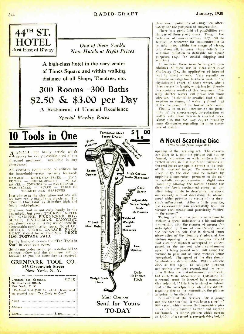
344
44TH ST. HOTEL
Just East of B'way
RADIO -CRAFT January, 1930
One of New York's New Hotels at Right Prices
A high -class hotel in the very center of Times Square and within walking distance of all Shops, Theatres, etc.
300 Rooms -300 Baths $2.50 & $3.00 per Day
A Restaurant of Unusual Excellence
Special Weekly Rates
10 Tools in One
ASMALL but handy article which serves for every possible need of the
all -round mechanic. Invaluable in any emergency. An excellent combination of utilities for the household -every necessity featured: 1L MIMER - KNIFE -SHARPENER - NAIL - PULLER - BOTTLE-OPENER - SCREW- DRIVER - CORK- SCREW - CAN- OPENER - WEIGH-SCALE - RULER - TABLE OF
WEIGHTS AND MEASURES
Just glance at the illustration and you will see how really useful this article is. The "Ten in One Tool" is 10 inches high and finely nickel -plated. The new tool is not only handy in the household, but every TOURIST, AUTO- 1ST, CAMPER, PICKNICKER, BOY - SCOUT, FISHERMAN, CANOEIST, etc., should carry in his bag one of these in- dispensable combination tools. No SHOP, OFFICE, STORE, GARAGE, FARM, BOAT, should be without one. PRICE S1.00, POSTAGE PAID. Be the first one to own the "Ten Tools in One" in your own town. Send your order today, pin a dollar bill to coupon below and the shipment will go forward to you the saute day as received.
GRENPARK TOOL CO. 245 Greenwich Street
New York, N. Y.
Grenpark Tool Company, R.C.-130 245 Greenwich Street, New York, N. Y.
Enclosed find $1a0 for which please send me prepaid your "Ten Tools in One."
Name
Address
Town State
steel N,°'°'
Tempered Steel .p 1
00 Screw Driver
%it.= á - IAe <,*e eo
Bottle Opener High Carbon
Knife Sharpener
5' Inch Steel Rule
Cork Screw
Adjustable Screw Weigh
Scale 15 Pounds
Table of Weights
and M
Weigh Scale Hook
Can Opener
Only 10 Inches
High
Mail Coupon
Send for Yours TO -DAY
there was a possibility of using them alter- nately for the purposes of conversation.
There is a great field of possibilities for the use of these short waves. Thus, in the technique of communication, they will be serviceable wherever the communication is to take place within the range of vision, but, above all, in cases where definite di- rectional radiation is desirable for signal purposes (e.g., for coastal shipping and aviation).
In medicine there seem to be great pos- sibilities of their use in ultra- short -wave diathermy (i.e., the application of internal heat by short waves). Very recently an intensive investigation has been made of the physiological effect of short waves, about three meters in length, which has led already to surprising results at this frequency. Pos- sibly shorter waves will prove still more effective. It should be recalled that an ab- sorption maximum of water is found just at the frequency of the 14- centimeter wave.
Finally, let us call attention to the possi- bility of the spectroscopic investigation of matter with these four -inch spectral lines. Along this line we may expect probably many discoveries regarding the inner struc- ture of matter.
A Novel Scanning Disc (Continued from page 31 -t)
opening of the receiving set. The chances are 2,307 to 1, that the picture will not be framed, but askew, or with portions in in- verted order; so that the outer portions of the sent image are apt to appear in the body of the received image. To overcome this irregularity, the disc mast be braked by applying a momentary pressure on the mo- tor spindle, or perhaps -for a slight mis- frame -by blowing the breath against the disc; tue feeble mechanical energy so ap- plied being ample to decelerate the speed momentarily without disturbing the normal speed which prevails by virtue of the rheo- stat's adjustment. After a little practice, the experimenter can successfully hold his picture rock -steady and practically "nailed to the screen."
'frying to tune in a picture or silhouette without a speed indicator is a hit -and -miss proposition, with the chances of success far outweighed by those of uncertainty; since the technician's sole clue is derived from observation of the blending shadows at the picture opening. A brief analysis reveals that even the slightest overspeed or under - speed, at the moment when synchronous speed is being passed over, will cause the picture to pass out of view without being recognized. 'l'he speed of the disc should he absolutely determinable. With a 48 -hole disc, at 9(10 r.p.m., 15 complete pictures are corning over each second, and the neon - tube flashes are instantaneously prodced; but each flash-occurring in 1/34,560th of a second -must be located by a scanning - disc hole and, if this hole is ahead or behind that of the corresponding hole of the distant scanning disc at the transmitter, the picture is going to be distorted.
Suppose that the receiver disc is going one per rent too fast; it will have a speed of 909 r.p.m., which means that successive pic- tures are progressively farther and farther misframed. A single picture which occurs in 1 /15th of a second is recognizable; but, if
January, 1930 RADIO -CRAFT 345
this has superimposed upon it, 115th- second
later, another picture substantially identical with the first, but overlapping it by one
per cent, it is apparent that the sharpness of outline is destroyed. If a continual suc-
cession of such progressively- overlapped pictures are being defined by the small opening of the television receiver, nothing but a cloudy surface of pinkish light ap- pears; although each and every picture, in- dividually, is perfect. Under conditions of one per cent off speed, the accurately framed pictures appear only once for every 100
pictures registering ón the disc; so it is easy to see why synchronism is the key to television.
Persistance of Vision Applies Also to Reading Speed
The speed indicator is of the familiar centrifugal type. A spring is opposed to a sliding speed-pointer which, being a (lull black, contrasts with the buffed background of the whirling disc; so that, as the disc speeds up, and the pointer moves farther and farther away front the axis of rotation -because of centrifugal force -a black cir- cle of constantly -increasing size appears on
the face of the disc. Through the persist - ance of vision, just as when a spark is
twirled around at the end of a string, the circle appears stall' ary at any fixed speed.
On the face iof the (lise is scribed n circle, which registers with the whirling- pointer circle when the speed is 900 revolutions.
Television in Colors (Col, in a / from pa or :H;)
same manner in which vthicc frequencies are controlled; that is, by It nipulation of "gain" and "fader" circuits (Fig. E).
For color television, the three images must be received in their appropriate colors, and viewed simultaneously and in superposition. 'l'he first problem was to find light sources which, like the neon lamp previously used, would respond with the requisite fidelity to the high -frequency signals of television, and at the sanie time give red, green, and blue light. With such lamps available, a decision would have to be made as to how the three colors could best be combined to form a single image.
Several methods of reception are possible. For displaying the transmitted image to a
large audience a big, zig -zag grid could be
employed; but it would consist of three parallel tubes, instead of a single one used in earlier television demonstrations in one
color. Tints far the television images have been
received in a manner similar essentially to the method for monochromatic television. The surface of a disc similar to that used
at the sending end is viewed, and the light from the receiving Iamp is focused on the pupil of the observer's eye by suitable lenses.
To combine the light of the three lamps, they are placed at some distance behind the scanning disc and two send-transparent mir- rors are set up. at right angles to each other, but at 45 deg. to the line of sight (as shown in the upper right of cabinet, Fig. II). One lamp can be viewed directly through both mirrors, and one lamp is seen by reflec- tion from each, as illustrated by the schem- atic diagram (Fig. G).
Obtaining Blue and Green
The matter of suitable lamps to provide the red, green, and blue light has required a great deal of study. There is no diffi- culty about the red light; because the neon
glow -lamp which has been used previously in television can be transformed into a suit- able red light by interposing a red filter. For the sources of green and blue light, however, nothing approaching the efficiency of the neon lamp was available. 'l'he de-
cision finally Intone was to use another one
of the "noble gases " -orgon -which has a
very considerable number of emission lines in the blue and green region of the spec-
trum. Two argon lamps are employed; one
with a blue filler to transmit the blue lines, and one with a green filter transparent to the green lines of its spectrum.
These argon lamps, unfortunately. are not nearly so bright as neon lamps and it was,
therefore, necessary to use various expedi- ents to increase their effective brilliancy. To work at high current intensities, special lamps were constructed with long narrow cathodes, made hollow so Moot streams of cold water could cool them. The cathode is
viewed end -on; this greatly foreshortens the
thin layer of glowing gas and thus increases
its apparent brightness. Even so, it is neces-
sary to operate these lamps from a special output amplifier to obtain currents as high as 200 milliamperes.
The Receiver
The receiving apparatus, at present, con-
sists of one of the 16 -inch television discs
used in earlier experimental work. Behind it are the three special lamps and a lens
system which focuses the light into at small
aperture in front of the disc. The observer, looking into this aperture, receives (through each hole of the disc as it passes by) light front the three lamps-each controlled by its appropriate signal front the sending end.
When the intensities of the three images
are properly adjusted, he sees a combined image in its true colors, and with the gen-
eral appearance of a small colored motion picture.
Technical Difficulties
Satisfactory television in colors is a far more difficult task than monochromatic tele- vision. Errors of quality which would pass
unnoticed in an image of only one color may be fatal to true color reproduction, where three such images are superimposed and viewed simultaneously. In three -color television, any deviations from correct tone rendering destroy' the balance of the colors; so that, while the three images might be
adjusted to give certain colors properly, others would suffer front an excess or (le-
ftciency of certain of the constituents. A further source of erroneous color exists at
the scanning end; if the light front the
object is not distributed equally to all the
cells, the object will appear as though il- luminated by lights of different colors shin-
ing on it from different directions.
Color television constitutes a definite fur- ther step in the solution of the many prob- lems presented in the electrical communica- tion of images. It is, however, obviously more expensive, as well as more difficult, than the earlier monochromatic form; for it involves the use of extra communication channels as well as additional apparatus.
his Free Book shows
how you can get into
AVIATION
Walter Hinton
First to pilot a plane across the Atlantic. arse to fly front North to South . \merles. first to use the plano In exploration. first world-famous flyer to
Rire hone -.study stu- dents the cream of his knowledge. Get Walter Iflnton's owo message to you. his Free (took, "wings of Opportunity."
HERE'S the book that tells
lust iv here your chances :ire
In Aviation today. It River defi- nite answers to the questions you're been asking yourself- What does At lotion offer me t' -"What must 1 do to get Into Aviation t" - "What job can I hob]?" It explains how Lieu- tenant Walter Hinton, through a remarkable per,onalized home - study course can give you - ltIG11T AT /JONI e: - the ground- work employers demand. This IN end h e home -study urse In Aviation Is getting cash results for if inlnu'.r graduates in all Parts of the country. Ile also hacks you up with an active em- ployment service when you are ready for a job. If you rant to take rep flight instruction. he arranges for special reduced rates at an accredited flying school.
Send for this book today. Tho time you now spend thinking that Aviation could be spent in raining.
Walter Hinton, President 301 -C
Aviation Institute of U. S. A. 1115 Connecticut Ave., Washington, D. C.
Please senil nie your Free stook showing how I can train right at home for a place In As I at Ion.
Name Age (mu .t he Is)
.\ddress
ety State
---- _J
LIFE -TIME DX AERIAL
Guaranteed Double Volume and
Dl :s('RIPTION Or LIFETIME Dr AERIAL No. 30- LENGTH 30 FEET: Assembled ready to string up. Brings in volume of 150 -ft. wire but retains the selectivity of a 30 -ft. aerial. Rings are heavy gauge solid zinc. Duplicates in design and non -corrosive materials the aerials used by most of largest Broadcasting Stations. Design permits using this powerful aerial in 30 -ft space (preferably outside). Sharpens tuning of any re- ceiving set because of short length but has enor- mous pick -up because 150 ft. of No. 14 enamelled wire is used. Made for owners of fine radio sets who want great volume on distance without de- stroying sharp tuning. (Also used by many owners of short -wave outfits.) "Makes a good radio set better."
510.00
No. 60- LENGTH 60 FEET: Assembled ready to string tip. "li Ili lit)Y" Size (same description as above except that 30) ft. of wire is used, making this the most efficient and powerful aerial possible to manufacture).
PRICE 512.50
3fannfarfurrd by TIIOROLA RADIO PRODUCTS
1014 So. Michigan lilcd. C'hieogo, Illinois
RADIO BARGAI10f5 Brand new 7 -tube A. C. chassis, guaranteed S29.75 Short wave 1 -tube sets 4.75 rsed 5 -tube radios. table models. Require
minor adjustment 6.90 Poster Transformers and Condenser (mocks at extremely low prices, Send for bargain list of gets, accessories and parts.
CHAS. H00DWIN CO. 4240 Lincoln Ave. Dept. A.15. Chichi
DEALERS IN BANKRI;I°r RADIO STOCKS
34h RADIO -CRAFT
CanYou Outguess O.Henry e. I in look alit ad in :. . Ilanet story aunt see the one. port, tit
rr, oncost. the strange twists of plot, the breathtaking finish? Try it? If tam succeed can can out-think the host Minds in the world, for the genius of O. Henry sets the wits of the brilliant people of all lands working at top -peed- -' nd still he amazed them all! Ile is the supreme muster of the "trick" ending, luring you into sudden laughter while a lump still lingers in our throat - making pia gasp by a sudden livid Hash of horror in the midst of a >ntuothk flowing tale.
Stories of Wit and Pathos Gentle 1: O. Holly. ant manly strength glut, in t tr tirite sett- tone; n,e; trader ttt,i,' suffering: lter kind to the under dos; chuck- ing tttth fin light beamed -
miraning In p s from his unplumbed depths of motet stitching the park - ling crystal of sincerity. .t great wilier. . t the mu entertaining
lid tit, til st
ing roe panl,nt. Heading hl: stiles i< lit Il.tcldng to u
The Master Story
Teller
((I
,a
tore br111lant tare- teller than eat r knew. Ills stork tu tea.urably mer
t ich the hailed library. , and grave the shelves of the most rrnnded.
53 BEST STORIES Less than 4 cents each $1.97 l'uu are new attar, ed for the first
tittle 3engnnt -icrg. doing. selected
awl durably bound In leatherette, At:111044i nilh god. Sal page:, all tar tir mire of only ono ordinary shun motel.
Why 1)0 YOU READ?
P o r -ntrrtaln- n tape
ram l'
daily t tirth- l'or re-
Inant :e.. d,enttt re. thrill : TO sharpen -our tä19
e sour rnuWr.'. w'i,at- ter >
o. our 1111,0.1. xomo
a limll'--eye on ,s, ry gelid.
- - - - CUT PRICE COUPON - - - - -f
GRENPARK COMPANY. Dept. R.C.130. 1245 Greenwich St., New York, N. Y.
Please send me O. lirnry 's hest Soule, at the Cut I I r 'rite of ELn7. 1 enclose stamps, Ott it or 31. EL
r r the amount. (check u
I Natue
%dd. -,s
rally and state 1.
PATENTS TRADE -MARKS
DON'T LOSE YOUR RIGHTS TO PATENT PROTECTION
Before di- eining s mur invention to anyone st lid (tor Li :ark farm "h:e1- 1,r.N11. to CO, e e r r tux" to be igncd .und ti in,r.t tt.
LANCASTER S. ALLWINE Registered paient sanrrt>r
475 Ouray Bldg., Washington. D. C. Originates of ternis "Et Ilene of Conception"
SONG WRITERS! ~ e+. Substantial Advance Royalties w ' ít tti are paid on work found acceptable for pub-
.- Anyone wishing to write nth, -- the word. or music for nonge may submit
work for free examination and advice. Past rsperienee unreeesaary.New demand created by 'Talking Pictures ". fully de- oeribrd in our free book. Write for it Today- Newcomer Associates 51 Earle Building, New York. N. T.
Screen -Grid Tubes (f oaliatterl /runt palle 321)
not exceed ;5. The control grit) is brought out at the top of the bulb, as in the '22 type.
As a Radio-Frequency Amplifier In order to obtain stable operation in
circuits desig ied to give normal gain per stage, it is necessary to use shielding to separate the input and output circuits. The internal shielding of the tube makes neu- tralization unnecessary. provided extraneous external couplings are eliminated by means of shielding. Suitable ventilation, however, nnist be prodded through the shielding to present excesise tube temptratures. Ra- dio- frequency filters should he used in cir- cuits employing more than two stages. and also in circuits which are desigucd to give the UM xiIn uu amplification per stage. The high plate circuit impedance necessary for obtaining the normal ;11110 fic:it' may be obtained either with eh»uily- coupled R.F. transformers or by means of the tuned - platc- itiipcl :once method.
As a Detector
The '21 is an excellent bias detector, with either small or high signal input. 'Pitt' screen -grid voltage' and control -grid bias should he so chosen that the roah'nl grid tau, .. oaf xi:ing It) a pouf where grid rrn- orel fa dr,r.'is. For small 111'. signals, when a. first audio stage is used, it is hest to operate the screen grill at :13 or 15 volts, and the control grid at 3.5 or 4.5 volts, (negative) respectively.
Fig. 3 is a typical schematic diagram Of a circuit in whid i the A.('. screen -grid tube is ounployell both as a radio - frequency am- plifier and as a detector. f)ni' method of shielding the circuit is suggested by the dotted line; ;it the bottom are shown the connections In the base and socket of the tube.
The 7 -Grid Tube (c',,,rl;ir'If i front page 0321)
thirty-two and sixty milliamperes, under the eurrrat In:n'uiettic pressures. The tube, however, being enclosed in the usual glass vessel, and the air exhausted, the barof nettle lnssuro. so far :is the grid biases are con - crned, may be left out of our calculations for the present. The rcasnn is that the mu- tual eouuduet:uee gives a rather undistorted output at normal plate current.
Result
From this rather technical description, it may be gathered trim simple it is to now calculate the final result, which gist's us the tut:d amplification factor: and which shows also the reason why the tube' works better at sin level rather than at high alti - tudes. The calculation for the amplification factor is as follows:
Due to the fact that a negative filament voltage is used and that, consequently, the flow in amperes is minus two, this, multi- plied by the thirty milliamperes mn the other side is again Inultiplietl into the normal plate voltage of 250. This product, multi- plied by the electrn omission of 2,658,999, gives a mutual conduct ;utce of approximately eight' -three billion. Again multiplying this by the "mu" factors of 7, we arrive at the
January, 1930
Staggering total of a net amplification factor of forty -eight trillion, which gives us the REAi. Iuuplifieation factor of this tube.
From which it may be gathered that, if we use this tube, no other instruments of any kind are necessary and, by simply hook - ing the tube to an aerial and ground, and using nothing but a loud speaker, we should get the most wonderful inu.ie with ear- splitting intensities.
The fact, however, is that nothing of the sort happens, for the good and sufficient reason that (if you have survived thus far, you may have guessed it!) the beautiful seven -grid tube is nothing but an excellent April First ,joke constructed by Baron von Ardenne for the amusement of his friends.
Tube Testing (Continued from pane :323)
for a number of characteristics. These in- eluded the filament current, the filament emission, plate current, "gas current," elec- trical leakage, amplification constant, plate resistance and nnitual conduction. In some of the smaller factories, tubes are still tested by hand; but it is not possible to use this Method in the largest plants, as too great a ltitaber of hand -test machines would be nee - ess:n'y, with a corresponding number of operators.
It must he realized that it was very diffi- cult to maintain each of the test units so that each would keep the same degree of accur- acy. In other words, if a battery setting Wert. wrong, a meter off calibration, or a circuit did not always tnake perfect con- tact, some time might pass before the ma- chine operator would discover the discrep- ancy : and this would cause the rejection of a nnnther of good tubes or, what is worse, a
number of poor tubes might be passed on. tisu, flu` operators of the hand machines
were not infallible and some poor tubes were always passed on.
Machine Testing
Under the spur of a real need for test cquiptiunt fintetioning with super -human speed and accuracy, it machine has hew made which automatically sorts the tunes into grumps -Ihuse with broken filaments; those with lots' emission, or "gassy" ones, as well :is those with high leakage between the elements; those with rharactcristies out- side of the specified range of plate current; and fourth. the good tubes. Ity classifica- tion of the defects in this way, it is possible for the engineers to trace hack the sources of trouble and make the necessary correc- tions. ('Phis single fact alone means a great benefit to the tube user, in the foram of a dependable product).
The machine consists of an electrical con- trol- hoard. ,joined by mans of a cable to the mechanical apparatus which connects the tubes in siuecssinn to the carious test cir- cuits. An automatic loading device with moving belts hoes, ys the good and the de- fective tubes separately away front the machine.
The fundamental idea of the tester is that tubes the automatically placed in it socket and. by uuans of a rotating dis,' equipped with rontart rings and brushes, they are suceessicely eonntct,wl into electrical cir- cuits specially designed to test for the de-
sired characteristics. The circuits are also
T
January, 1930
designed so that they operate an ejector which will throw out a tube which is defec- tive in any test. A control relay with a sensitivity of .05 -tea. (each control relay is nothing hut a meter; a contact anii being substituted for the indicating vane) releases the ejector relays, so that tubes which pass each test satisfactorily are permitted to travel on to the next. The arrangement of the contacts is such that the test circuits allow the meters to conic to a fixed position before the ejector circuit is connected.
The ejector consists of a solenoid which pushes the defective tube into the entrance of a chute; and a good tube must pass three of these chutes before it is finally delivered as O. K. by the machine. 'The diagram of the test unit is shown in *Fig. 3, so that interested technicians can get an idea of the arrangement.
Four Rejections
The first circuit is designed to eject tubes with defective filaments; this classification in- cludes open filaments, short -circuits between the filament and the plate, and short -circuits between the grid and plate. The circuit con- sists of two telephone relays, a protective resistor, and a power- control relay which operates the solenoid. The second circuit removes tubes classed as- gassy, leaky (with leaks between filament and plate or between grid and plate), or with low filament emis- sion. The automatic tube tester also makes a double check on the first test, by the sec- ond circuit's also rejecting the tubes under that class. The third circuit rejects tubes with either low plate current or high plate current. The diagram will give some indi- cation as to just how these tests are made -at a speed of 8,000 tubes per hour.
The information for this test unit is token from a paper published by the "12adio Club of America," r,Mcb may be obtained from Mr. L. G. Parent, Chairman of the committee, 91 Seventh Avenue, New York City.
From Microphone to Modulator
(Continiu-d imam I,aye 325)
the Spiltntore Ballroom through KNX -" A relay clicks minutely in the large speech-
amplifier panel behind us, and a red light suddenly flashes in the right -hand corner of the switchboard.
` -the Paramount Pictures -Evening Ex- press Station, Ilollywootl, California. The next number will be u violin solo entitled `Caprice Viennois,' by Kreisler, played by Cahoon Luboviski'
The red pilot goes out and at the same time another flashes just below. The studio at our left, which has been softly illumi- nated by indirect lights concealed near the ceiling, suddenly brightens, and through the plate glass window we see I.uboviski lift- ing his how to the strings of his violin.' With a yawn the operator picks up the telephone, depresses the black talking key, and mur- murs, "Well, so long, Bill"
IIe throws the red switch, and the pair of extension -circuit pilot lights go out. "Thus endeth the Spiltnrore hour," he com- ments.
"Well," we inquire, puzzled by this per- formance, "what happened ?"
"You have seen," replied the operator, "what is known to the trade as a 'split-
RA1)IO- CRAFT
sentence change -over. As the announcer waS on duty hi the next room, I let him manipulate the eontrols, although they are in duplicate so that I can announce from this desk if desired. The instant the announcer uptown pronounced the words `KNX; our announcer next door pushed a couple of buttons on his control cabinet and cut over from the extension line to his own mike, finishing the sentence.
"'live upper red light shows that the an- nouncer is on the air. The one just below is a microphone pilot, placed in series with the tube filaments of the audio amplifiers that are part of the condenser- type Micro- phones. If a tube burns out, we know it.
"The announcement goes out over the public -address system that reaches every room in the studio, :utul wherever Mr. I.u- boviski goes, he is pursued by a I 1
speaker, so he cannot help knowing when it is his turn to play. Furthermore, when the announcer 'cuts over' to the studio after making his announcement, the remaining. half of the lights in that room go on. half of them are already burning, hit the bright- ening of the room warns the artist that the microphone is `:dive,' preventing any slips."
IIe fingers one of the group of knobs in the north central part of the switchboard. "'Phis is the microphone mixing panel, and these knobs do the mixing. Any or all of the six studios can be put on the air at the snore time. Local programs can be broad- cast simultaneously with field events, or as nanny as eight separate programs can be superinlposel upon one another -if any - body wants to listen to then. They can be 'faded-in' to one another and Mixed in any desired proportion.
The "Monitoring" "The loud speaker you sec is not oper-
ated from the same publie-address system as the others. We arc more exclusive in this department; our program comes, not from the common source, but from a super- heterodyne tuned to KNX's wave; so that we hear our own programs just as they sound outside. It is therefore unnecessary, when a cockroach gets into the microphone or a modulator has a fit of the collywobbles, for all the listeners within an airline radius of fifty miles to call us on the telephone and tell us about it. It sounds even worse here to us than it does to them. 'l'hat is no joke, however, about the number of calls. Not long ago, when some one deliberately interfered with a certain speech broadcast through n local station, so mean' calls cane in that the battery of the nearby I- inlly- wood telephone exchange was run down!
"These two big knobs are the master gain controls, by means of which we keep the sound level within reasonable l' -ts. The speech currents are mixed, amplified twice, and then sent through the `equalizing pads' over the telephone wires, amplified again in the telephone exchange, and yet again at the station before entering the modulator. 'l'he `monitoring' is done here, and the needle of the meter is not allowed to swing past the red mark on either side of zero. All equipment is, of course, in duplicate, as an emergency measure. Accidents are rare; but here is something that in sudh emer- gencies does more than any other thing to save technicians from the padded cell."
He turned to the large speech amplifier panel and indicated a square switchboard section, set just beneath time long black
347
LIGHTNING ARRESTER
Also Ejects Static Charges Improving Reception
The Corwico Vulcan Lightning Arrester Is manufactured in accordance with a new engineering principle that protects your radio against damage from light- ning and also dissipates accumulated static charges. Buy one today for light- ning protection and better reception.
AT YOUR DEALER'S OR DIRECT UPON RECEIPT OF PRICE
CORNISH WIRE CO. 36 CHURCH ST., NEW YORK CITY
MAKERS OF THE FAMOUS
Aluminum Box Shields Beautiful silver dip finish, 5 "x9 "x6 "- $1.75, We make any size to order in 24 hours,
Muter miniature S.P.D.T, Switch 19c.
Yaxley switches always in stock.
All types of adapters. Full stock of Weston,
Jewell and Readrite meters.
Full stock of Amertran, Pilot and Odo -Coil forms and coil shields.
Genuine Baldwin Type "C" phones, a necessity for short -wave recep tion, $3.65 a pair.
Brach TEST -O -LITE fits your vest pocket, $1.50 . postage prepaid.
Rider's Trouble Shooter's Manual- $3.50. Rider's Treatise on Testing Units -$1.00.
BLAN THE RADIO MAN, Inc. Est. 1923
89D CORTLANDT ST. NEW YORE]
fi
TRI -STATE HEADQUARTERS Pennsylvania- Ohio -West Va.
WHOLESALE RADIO To DEALERS and SET BUILDERS we offer
the must prompt :old emrlenl er. i, we *v handle only ale bed merchandise, and Cive MAXIMUM DISCOUNTS.
GET OUR CATALOG * AMFRADIO 430 WOOD ST. at O:amo+.ae sr.
PITTSSV1fZOH PA. II-hen writing to advertisers, pdeaxc
mention 1t ADIO-CR AFT.
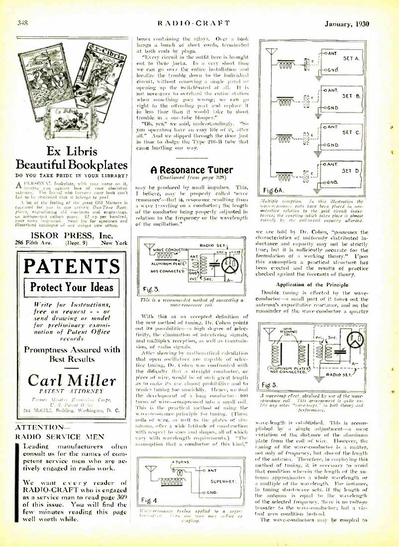
3-18
Ex Libris Beautiful Bookplates DO YOU TAKE PRIDE IN YOUR LIBRARY?
Al'ERse1N. \f. bookplate. with your name on it,
insures you against loss of your cherished volumes, The friend who borrows your book can't fail to be reminded that it belongs to you!
.\ bit of the feeling of the great Old Masters is raptured for you in our artistic Duo-Toler Book- plates, reproducing old woodcuts and engravings, on :unique -tint vellum paper. S2 up per hundred, .our )maw imprinted. Send Ise for specimen and illustrated catal,.gne of our unique new series.
ISKOR PRESS, Inc. 286 Fifth Ave. (Dept. 9) New York
PATENTS Protect Your Ideas
Write for Instructions, free on request - - or send drawing or model for preliminary exami- nation of Patent Office
records
Promptness Assured with Best Results
Carl Miller IJ.4TEA'T ATTORNEY
F.rnur 31er11r,n l:.ron:húatt Corps, r. S. littwt O:
265 \icl;I1.1. Building, Washington, D. C.
ATTENTION- RADIO SERVICE MEN
Leading manufacturers often consult us for the names of com- petent service men who are ac- tively engaged in radio work.
We want every reader of RADIO -CRAFT who is engaged as a service man to read page 309 of this issue. You will find the few minutes reading this page \veil worth while.
RADIO -CRAFT January, 1930
boxes containing the relays. Over a hook hangs a bunch of short curds, terminated at birth ends by plugs.
"Every circuit in the outfit here is brought out to these jacks. In a very short time we can go over the entire installation and localize the trouble down to the individual circuit, without removing a single panel or opening up the switchboard at :ill. It is not necessary to overhaul the entire station when sraridhing goes wrong; we van go right to the offending part and replace it in less time than it world take to shoot trouble inn one -tube blooper"
"Oh, yes," we said, understandingly. "So you operators have an easy life of it, after till." Arid we slipped through the floor ,just in time to dodge the Type 216 -B tube that came hurtling our tt,iy.
A Resonance Tuner (Continued from page 329)
may be produced by small impulses. This, I believe, may be prupeiiy called `wave resonance' -that is, resonance resulting from it wave traveling on a conductor; the length of the conductor being properly adjusted in relation to the frequency or the wavelength of the oscillation."
This is a recommended method of connecting o trave -resonance coil.
With this as an accepted definition of the new method of tuning, 1)r. Cohen points out its possibilities- a high degree of selec- tivity, the elimination of interfering signals, and multiplex reception. as well as transmis- sion, of radio signals.
.1fter showing by mathematical calculation that open oscillator. ;nee eapalrlr of mice- live tuning, I)r. Cohen tuts eontlonted with the ditlìrulte that a straight rontlnctnr, or piece of wire, %multi be of such great length as to make its use almost pruhil,itise and to render tuning too unwieIdly. I lane[. we find the dcichgnnent of it long conductor loo turns n1' ,ire-- compressed into a small coil. This is the practical method of using the tt .n e- resonant' principle for t (These arils of wire, as well as the plates of alu- miuum offer a wide latitude of construction \Vitt) respect to sizes and shapes, :dl of which \ :11'y with wavelength requirements.) "The ,sutnption that it conductor of Ibis kind;'
I I'o'n ratona r ce tu u iuo applied to a soper- i,el,r.,,l'v.e. I 71'11 or taira mage or ft'icc as
coupling.
111
I 11
11 1
-
fl;l c
i)J
e:
-o ANT.
G ND.
SET B.
o ANT.
GN D.
SET C.
O ANT.
GND.
SET
Multiple reception. In this illustration the mare -resonance coils have been placed in nou- inductive relation to the grid circuit induc- tances; the coupling which fakes place is almost entirely by the coil -to -roil capacity afforded.
we are tolet by Dr. Cohen, "possesses the characteristics of uniformh' distributed in- ductance and capacity may not be strictly truc; but it is sufficiently accurate for the formulation of a working theory." Upon this assumption a practical structure has been erected and the results of practice checked against the forecasts of theory.
Application of the Principle Double tuning is effected by the wave -
conductor -a small part of it tunes out the antenna's capacitative reactance, and on the remainder of the wane- conductor a quarter
arS VONNCE CaiS
r----
sec.
ALUMINUM MATEO NOT CONNECTED.
Fig. 5.
RADIO SET.) 1
A Ceara -trap effect, obtained by use of the ware - resonance coil. This arrangement is quite un- like any other a-ore traps, in both theory and
performance.
wave- length is established. This is accom- plished by a single adjustment-a mere variation of the distance of the al plate from the coil of wire. Iíowever, the tuning of the wave- conducbir is a matter, not only of frequency, but also of the length of the antenna. 'l'bcrefure, in employing this method of tuning, it is necessary to avoid that condition wherein the length of the an- tenna approximates a whole wavelength or a multiple of the wavelength. For instance, in tuning short -wave sets, if the length of the antenna is equal to the wavelength of the selectee( frequency. there is no voltage transfer to the wave -conductor; but a vir- tual zero condition instead.
The wave- conductors may be coupled to
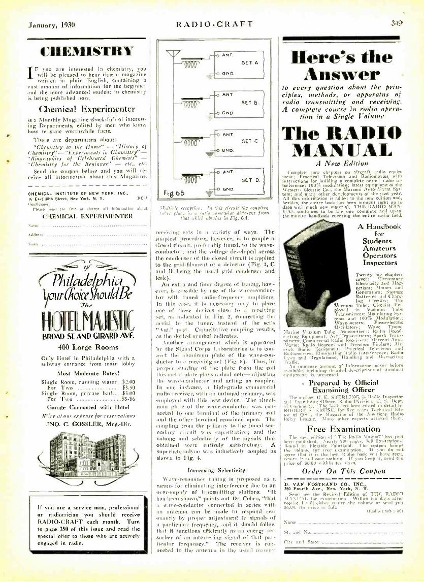
January, 1930
CHEMISTRY IF you are interested in chemistry, you
will be pleased to hear that a magazine written in plain English, containing a
vast amount of information for the beginner and the more advanced student in chemistry is being published now.
Chemical Experimenter is a Monthly Magazine chock -full of interest- ing Departments, edited by men who know how to state worthwhile facts.
There are departments about: "Chemistry in the /tome" -"history of
Chemistry " - "Experiments in Chemistry" - "Biographies of Celebrated Chemists" - "Chemistry for the Beginner" - rte., etc.
Send the coupon below and you will re- ceive all information about this Magasine.
CHEMICAL INSTITUTE I6 East 30th Street, New
tient leine,,: l'lea.,o send me free
CHEMICAL
OF NEW YORK. INC., York, N. Y. 11C -1
of charge all luLmuat dun about
EXPERIMENTER vane
.t ddre ..
Town
PtitladelpAia 1o1 rr aoiee Sh ould 13e
7/te
1
BROAD SI AND GIPARD AVE.
400 Large Rooms Only Hotel in Philadelphia with a subway entrance from main lobby
Most Moderate Rates! Single Room, running water $2.00
For Two $3.50 Single Room, private bath $3.00
For Two $5 -$6
Garage Connected with Hotel Aire at our expense for reservations
JNO. C. GOSSLER, Mng: Dir.
If you are a service man, professional or radiotrician you should receive RADIO -CRAFT each month. Turn to page 350 of this issue and read the special offer to those who are actively engaged in radio.
RADIO -CRAFT 34)
If:fit:He reception. In this circuit the coupling tai., ¡!ace in a ratio 'omrtdtat different from
that trhfc1 obtains in Fig. 6.4.
retie lying leis in a variety of ways. The simplest procedure, however, is to couple a r!used circuit, prfcrnbly tuned, to the wave- conductor; and the voltage developed across the condenser of the dosed circuit is applied to the grid- lihiulent of a detector (Fig. 1, C and It dieing the usual grid condenser and leak).
An extra and finer degree of tuning, how- ever, is possible by use of the w :tvc- condue- tor with tuned radi- fregneney amplifiers. In this ease, it is ueeess:ny only to place one of these devices close to a receiving set, as indicated in Fig. 2. connecting the aerial to the tuner, instead of the set's ".\nt." post. Capacitative coupling results, as the dotted symbol indicates.
Another arrangement which is approved by the Sigurd Corps Laboratories is to con- nect the aluminum dilate of the wave-con- ductor to a receiving set (Fig. 3). 'thus, by proper spacing of the plate from the coil this metal plate plays a dual note -adjusting the wake- conductor and acting as coupler. In rue instance, a high -grade commercial radio receiver, with an untuned primary, was engduyed with this new device. The alumi- num plate of the wave -conductor tias Con- nected to one terminal of the primary coil and the tither terminal remained open. The coupling from the primary to the tuned sec- ondary eireuit WauS cnpaeittdive; and the volume and selectivity of the signals thus obtained were entirely satisfactory. A superheterudyi Was inductively coupled as shown in Fig. 4.
Increasing Selectivity Wave- resonance tuning is proposed as a
means for eliminating interference due to an over -supply of transmitting stations. "It has been shown," points out 1)r. Cohen, "that a wave- conductor connected in series with an antenna can be made to respond res- onantly by proper adjustment to signals of a particular frequency, and it should follow that it functions efficiently as an energy ab- sorber of an interfering signal of that par- ticular frequency." 'l'he receiver is con- nected to the antenna in the usual manner
Here's the Answer
to every question about Nie prin- ciples, methods, or apparatus of radio transmitting and receiving. A complete course in radio opera-
tion in a Single Volume
The RADIO MANUAL
A New Edition Complete new ch -pters on aircraft radio equip-
ment; Practical Television and Radiomovies with instructions for building a complete outfit; radio in- terference; 100% modulation; latest equipment of the \\'entern Electric Co.; the Marconi Auto -Alarm Sys- tem; and many other developments of the past year. All this information is added to the new edition and, besides, the entire book has bcen brought right up to date with much new material. TIIE RADIO MAN- UAL continues to be the one complete and up -to- the- minute handbook covering the entire radio held.
A Handbook for
Students Amateurs Operators Inspectors
Twenty big chapters cover: Elementary Electricity and Mag- netism; Motors and Generators; Storage Batteries and l barg- ing Circuits: The
Vacuum Tube; Circuit; Em- ployed in Vacuum Tube l'ransmitters; Modulating .y,-
tents and 100`b Modulation; Wave-meters; Piero-electric Oscillators; Wave Traps;
Marine Vacuum Tube Transmitter'; ]radin Broad- casting Equipment; Arc 'transmitters; Spark Trans- mitters; Cununcrcial Radin Receivers; Marconi Ant,- Alarm: Radio Beacons azul Direction Finders; Air- craft Radio Equipment; Practical Television awl It:uliumovies: Eliminating Itadin Interference; Radio I.:, ais : Handling Regulations; andling :unl .\bst ravi i,g 'lyre lije.
An immense amount of information never before available, including detailed descriptions of standard equipment, is presented.
Prepared by Official Examining Officer
The Author, G. E. STERT.TXi:, is Radin Inspector awl Examining Officer, Radio Division, C. S. Dept. Of Commerce. The book has been edited in detail by ROBERT S. KRUSE. for five .gars 'Technical Edi- tor of OST, the \l:tgazine of the .\ weric:ut Radio Relay Teague. Many other r its them.
Free Examination Thr new edition of "The Radio Manual" has jest
been published, Nearly 9u0 ages, 3o9 ilhutrations. Itound in Flexible Fahrikoi,I. The coupon brings the yohtme for free examination. If you do not agree that it is the hest Radio hook you have seen, return it and owe nothing. It yon keep it, send the price of $6.00 within ten days.
Order On This Coupon
D. VAN NOSTRAND CO., INC., 250 Fourth Ave., New York, N. Y.
Fend nie the Revised Edition of TETE RADIO \I: \ \t -. \I. for eNamination. Within ten das after receipt I will cith, -r re torn the volume or send gnu $6.M, the price in full.
11ladlo -cran t -S l
Nance ..
St. and Nn.
City and State
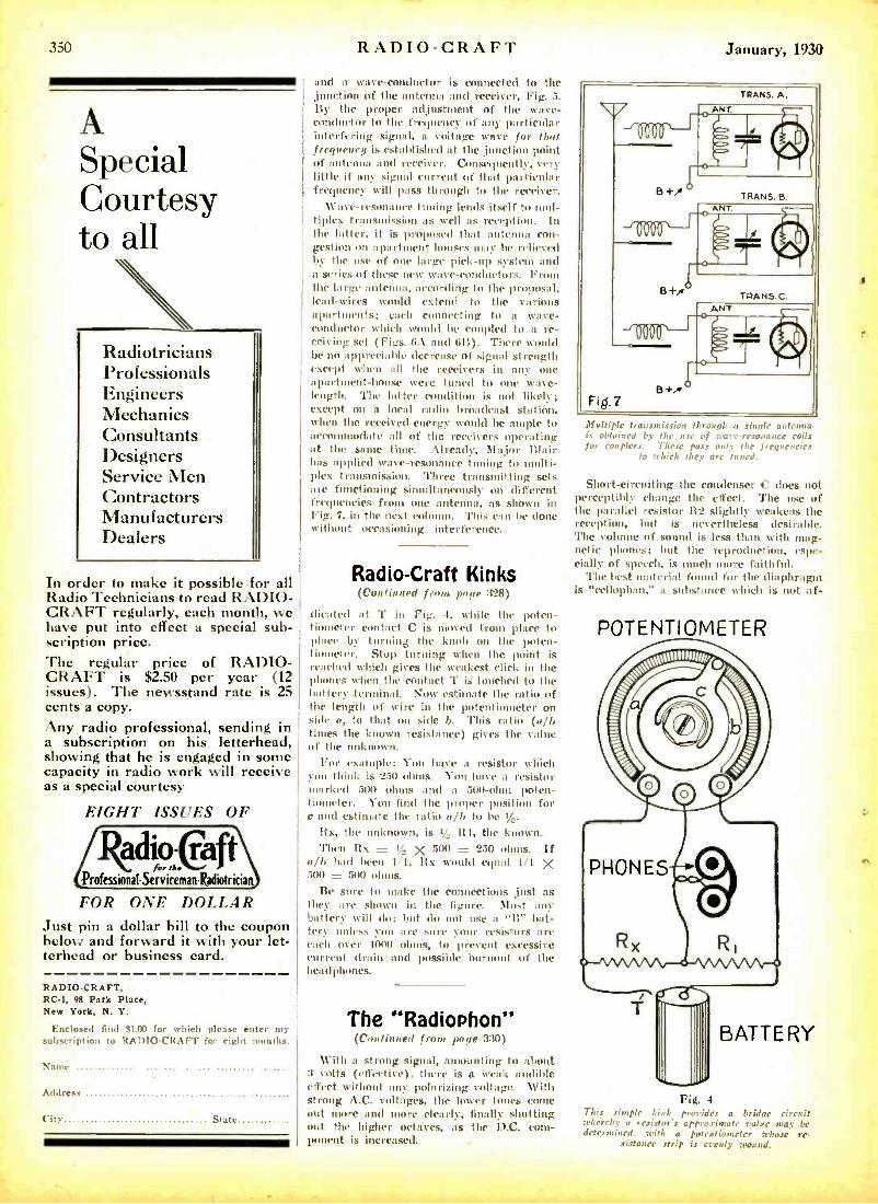
350 RADIO -CRAFT January, 1930
8
A Special Courtesy to all
Radiotricians Professionals Engineers Mechanics Consultants Designers Service Men Contractors Manufacturers Dealers
In order to make it possible for all Radio Technicians to read RADIO - CRAFT regularly, each month, we have put into effect a special sub- scription price. The regular price of RADIO - CRAFT is $2.50 per year (12 issues). The newsstand rate is 25 cents a copy. Any radio professional, sending in a subscription on his letterhead, showing that he is engaged in some capacity in radio work will receive as a special courtesy
EIGHT ISSUES OF
adio -Caf t for tit.
Professional -Serviceman lodiotrician
FOR ONE DOLLAR Just pin a dollar bill to the coupon below and forward it with your let- terhead or business card.
RADIO- CRAFT, RC -1, 98 Park Place, New York, N. Y.
Enclosed find $1.00 for which please enter my- subscription to RADIO -CRAFT for eight months.
Name
Mareue
City State
and a wave- conductor is connected to the junction of the antenna and receiver, Fig. 5. By the proper adjustment of the wave - conductor to the frequency of any particular interfering signal, a voltage wave for that frequency is established at the ,junction point of antenna and receiver. Consequently, very little if any signal current of that particular frequency will pass through to the receiver.
Wave-resonance tuning lends itself to mul- tiplex transmission as well as reception. In the latter, it is proposed that antenna con- gestion on apartment houses may he relieved by the use of one large pick -up system and a series of these new wave -conductors. From the large anteutta, ace,irding to the proposal, lead -wires would extend to the various apartments; each connecting to a wave - conductor which would he coupled to a re- ceiving set (Figs. bA and 611). There would be no appreciable decrease of signal strength except when all the receivers in any one apartment -house were tuned to one wave- length. The latter condition is not likely; except on a local radio broadcast station, when the received energy would be ample to accommodate all of the receivers operating at the same time. Already, Major Blair has applied wave- resonance tuning to multi- plex transmission. Three transmitting sets arc functioning simultaneously on different frequencies front one antenna, as shown in Fig. 7, in the next col . This can be done without occasioning interference.
Radio -Craft Kinks (Continued from palle 328)
;Heated at 'l' in Fig. 4, while the poten- tiometer contact C is moved from place to place by turning the knob on the poten- tiometer. Stop turning when the point is reached which gives the weakest click in the phones when the contact 'l' is touched to the battery- terminal. Now estimate the ratio of the length of wire in the potentiometer on side a, to that on side b. This ratio (gib tintes the known resistance) gives the value of the unknown.
For example: You have a resistor which you think is 250 ohms. You have a resistor marked 500 ohms and a 500-ohm poten- tiometer. You find the proper position for e and estimate the ratio alb to he t /,.
Ilx, the unknown, is }.. R1, the known. Then Bx = ! <, X 500 = 250 ohms. If
alb had been 1/1, Bx would equal 1/1 X 500= 500ohms.
Be sure to make the connections just as they are shown in the figure. Most any - battery- will do; but do not use a "It" bat- tery unless you are sure your resistors are each over 1000 ohms, to prevent excessive current drain and possible burnout of the headphones.
The "Radiophon" (Continued from page 330)
With a strong signal, amounting to about 3 volts (effective), there is a weak audible effect without any polarizing voltage. with strong A.C. voltages, the lower tones come out more and more clearly, finally shutting out the higher octaves, as the D.C. com- ponent is increased.
Multiple transmission through a single a tenma is obtained by the use of Tying..- resonance roils for couplers. These pass only the frequencies
to which they are tuned.
Short- circuiting the condenser C does not perceptibly change the effect. The use of the parallel resistor lt2 slightly weakens the reception, hut is nevertheless desirable. The volume of sound is less than with mag- netic phones; hut the reproduction, espe- cially of speech, is much more faithful.
The best material found for the diaphragm is "ecllophan.' a substance which is not af-
POTENTIOMETER
BATTERY
This simple /.ink pro-ides a bridge circuit whereby a resistor's approximate value may be determined, with a potentiometer Trhosc re-
sistance strip is only wound.
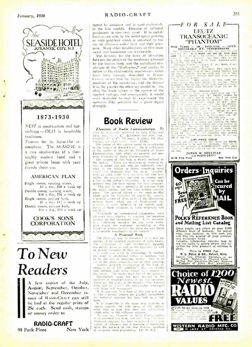
i
January, 1930
/le
SEASIDE HOTEL ATLANTIC CITY, NJ.
r ir
, , ,
'
/1,-1 ., . . ,
r PPf r
_'"E,. _ f.-t " f t+,
.lïl'l,>r1.Wgtltspr
1873.1930 NEW in construction and fur- nishings - OLD in hospitable traditions. Famous for its Inane -like at- mosphere. The SEASIDE is
a rare combination of a thor- oughly modern hotel and a
great private home with your friends about you.
AMERICAN PLAN Single rooms, running water,
$5 a day, $30 a week up
Double rooms, running water, $10 a day, $56 a week up
Single rooms, private bath, $7 a day, $42 a week up
Double rooms, private bath, ßi14 a day, $70 a week up
COOK'S SONS CORPORATION
To New Readers
\ few copies of the July, August, September, October, November and December is- sues of RAoto- CR:V'T can still he had at the regular price of 25c each. Send cash, stamps or money order to
RADIO -CRAFT QS Park race New York
RADIO -CRAFT 351
feeted be moisture and i. used eaehlsi'rl in the late models. Genuine or artificial parchment is ais,, very good. It is metal- lized on une side, h - the niet.il -spray process,
or with gold-leaf which is attached by the
use of albumen under heat and hide pres- sure. many other combinations of thin sheet
metal and insulators are serviceable. 'flic formula for the force of alIii,iion
between the plates of the condenser (Billed by the human body and the metallized dia- phragm of the "Itadiophnn," and similar in
action to the electrostatic reproducers which have liven recently described in It tun
t11) .loo\s that the higher the (Hided ri. Constant of the membrane, and the thinner it is, the treater the efficiency should he. tit, also, the force \;fries :Is lite xyun1'1 of the
applied von:i_(% and consequently it Ayoub! .,col desirable to hind by experiment the
optimum IL(. potenli:ll I.n' a given signal rt 1ength.
Book Review fìl era u'uh ui Radio CumurnuSntiON. Y
: rotl'li.rGrd Wiley and . C. (Chapman a+;d lfa/1, l.td.,
. .. 271) panes, b tables, 170 ilLts
The author of this cuhune needs uo introduction to the readers of Ito ut et.11 er r. Ile is troll -known as the :ouhnr of the classic, l'riuciples of lindi.. COMM, ll ¡Cal hill., with which we compare and con- trast Glnnculs of Radio Canm, a itatinn.
The purpose of this book is clearly outlined in the preface: "Tht re are thousands of students to- day, in school anti out, who are sufficiently inter -
c-ted in the subject to desire s -thing more .rod and thorough than the many -popular" .Is nu radio which have appeared, lot ho has
e -ilher the preparation nor lime to attempt such a test a, the author's Principles. It is for these students that the later col has been prepared.
"This test is not a collertinu of excerpts from the larger sulume, hot has I well written cutirl ly anew. The general scheme is the sank as that which
` t the /'iiueiplrs its popularity, haul. ly,
a g ad rt view of those parts of the alternating- current theory which are of fundamental inr- portaurr ill radio, followed by the specific :ygdi- cation of these principles to radio telegraphy and icl. rb,
"I'ru't irai ly no mat hrmat ical preparation, more aeb :nurI than algebra, is required for complete eta -tery of this elementary teat. It is, net critic- lo -nfìciently cumplcte fur any radio olahn- siast except the engineers spacial izing in this branch of cunununiratiou: for these the tost forms a reasonable introduction to the snhjcet."
A Practical Book TIM rt,- Hi'at.r may be con.id,'red a a text eN-
positir,n of the practical application of nadie theory, The derivations of each fundamental equation are clearly given as Hell a, the equation; as well as specific examples of their use.
\, each new point in terminology is reached, the n ord
'
is emphasized eitht r in lsddface type or by the Ilse of quotation marks. This is an aid to the ready rumprth, n.ion of their mt :wing.
. \unthtI' dl- irntde arrangement of the Is .uk itt- ctndrs a stf of 117 "problems- : tin y are Ili,; led into sections, each Indio; rlate.l to a chapter in the sohune. The reader must furnish the answers.
Considerable space has beau uttcultd to the prublrn,s of hruadea.t- station design and operation. 'there :or 150 p:lges in the chapter, "The \ acuunl Tube and its l's, -: ; the nmpupnlar sereeu -grid lithe being well represented.
It is net-ts,ary ire a (look of this size and style to lake a certain amount for granted; ncvtrthless the technical accuracy has born field to a high In't'el.
it is impossible in the space here available to picture prod oily the wide SCope of this volume., other than to stale that there arc solo-ho.lding which reft-r to 165 di iÏcreuu snharrts.
Tin sum np, Elements of Rob/ Coon nIol :..lie is :m rsctlleut 14X1 Io.ok, and " Technical scourge," has been maintained ` on Variety of snbjrcls; and it contains ill con'.. .
form the answers to the less abstruse of ever' -day radio engineering. (It. U. \V.) ,1
FOR S A L E - LEUTZ
rl'RANSOCEANIC "PHANTOM"
NINE TUBES - 100'. SHIELDING - INT FIt. CHANGEABLE R.F. TRANSFORMERS
,,.. i i t' . losa . I3 that I.. .
Ilt I brand new and has never b' I - .. 111 The 0 t or 1".
bcco lo.e.1 ort ti,-- i 1 I- an Licensed under
In.; depth. S (rt.; l i.. 1ont ul t r p.mrl Pire rhumb ro
II Il n 1 them ganged together mal I,. oo he flan Only, I a I really unh nw of Ili,.:
I I wl,ala ma't Idea SI age Wain, I 1 1 I
-1'u t ttl un. H for four r 11 f +
oy All511_ nie eti.. i- ,ovni, nor de te Im, r tort Oat. tor I ha tr.tilol ra.lio frequency
r0111111 I liroilenry .tags and u.
smolt. which gites Van "A"
- 'It " batter' reading b) en, o eight. No. 1 on
rit Boat of soli agit delect Or; NO-
,ll) - :1 n lita n.'m -ii ace on 1t.P. Nu itch gis - 0,11 '1' big al dr No t not cI' , Ida: on ILI'. No. win lI :. ',It" collage On .I u
N.O. nII I It" silage It I
016,5: No. 7 u -nit. ghrr ton It" cottage 11-; So. s m
luiiiii girr< )uu "1t' u.ltage pyt er t o r I uil01111 :
`
10 tube only. yt rrrr: Tito alt. seer oi, 7; mll,r n to 170. In naag No s in -tutu )uu molt Illy the upper
,rant n,,,ing by G t, loi. il bring; the vale reading a-
In Ton leu. The -r1 Inv four , taget of tuned radie I r,n r.. try. a dru,o.r. .,i four of audio fre- .IIll'... >. 'nier enemy binding I iuA' lin the ha4 lr
of -et for ' '.\. "rr'it," I'' haiieuirs, loin,, goba. and -ria key. 'l'nr, ltr.nnlonded: Stsflu 'Ill .\ .al -.\, one .111.
LIST PRICE 5250.00 1 ni II -ill chia -ri Io the tir -' I inner tor $50.00:
Irau- nortailon to he paid il purchaser. This set i
the Preoebto et ItAl /10- l'It.\FT, a'ldrh alone r hon.! br uni. tar eon o.. ola: Ihr .iloar -tawmen, alt. true.
JAMES W. SULLIVAN t,e RADIO -CRAFT
96.95 Park Place New York City
Orders-Inquiries Can be !cured
by 1AI L
POLK' REFERENCE BOOK and Mailing List Catalog Gives counts and prices on over 8.000 different lines of business. No matter what your business, in this book you will find the number of your prospec- tive customers listed. Valuable information showing how to use the mails to secure orders and In- quiries for your products or services is given.
Write for FREE Copy R. L. POLK & CO.. Detroit, Mich.
Largest City Directory Publishers to the World. Brunchee in Prinrlwl lilies
liftillimr List ` a t Statistic' Producers of Direct i Advertising
Choice of I,OO.;;:: Newest.. wK
R4DIOh. VALUES í./
N[)TfR g .í 1' rar our n ' e 1910
Fit:, I anazin 215 CUSS
1..'I n
..,` FREE WESTERN RADIO MFG. CO. ® w. LAKE ST. CHICAGO ILL.
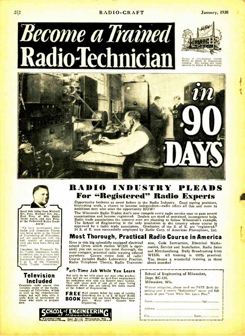
352 RADIOCRAFT
Become a Trained RadioTechnician
January, 1930
Towers of Broadcast hog Station WISN on S. hoot of Engineering Lulldhng. This station now being operated by School of Engineering.
Read this letter from Michael Ert, Pres. Michael Ert, Inc., Past Pres. of Wis. Radio Trade Ass'n, and now Pres. of the Federated Radio Trade
Ass'n: -We have investigated your Radio and Broadcast Course
rww being given at the School
á Engineering of Milwaukee, and are acquainted with the high quality of educational work you have been doing for years.
Therefore, the Wisconsin Ra- h. Trades Association hereby
authorizes you to prepareen la receive Radio Serviceman's Registration Card., elasses I: or C. of the Wisconsin Radio Trades Assi ciat iron."
1 r Television Included
Complete radio course also includes study of the funda- mentals of Television, which is still in the experimental stage, but will soon offer a wide field of usefulness to those who start to prepare now.
RADIO INDUSTRY PLEADS For "Registered" Radio Experts
Opportunity beckons as never before in the Radio Industry. Good paying positions, interesting work, a chance to become independent -radio offers all this and more to ambitious men who seize the opportunity NOW! The Wisconsin Radio Trades Ass'n now compels every radio service man to pass severe examinations and become registered. Dealers are tired of untrained, incompetent help. Radio trade associations the country over are planning to follow Wisconsin's example. The School of Engineering is the only institution in the country whose course is approved by a radio trade association. Graduates of the S. of E. are "registered." 14 S. of E. men successfully employed by Radio Corp. of American Photophone, Inc.
Most Thorough, Practical Radio Course in America Here in this big splendidly equipped electrical school (from which station WISN is oper- ated) you can secure the most thorough, the most compact, practical radio training offered anywhere. Covers entire field of radio! Course includes Radio Laboratory Practice, Radio Telephone Theory, Radio Transmis-
Part -Time Job While You Learn Not only do we help place our men after gradua- tion, but we can arrange for part -time employment for ambitious men who can finance their tuition. This will cover part if not all of your living expenses while you are taking the radio course at the School of Engineering.
FREE Mail coupon today for copy of catalog describing the S. of E. 90 days' Radio Course and our Earn -While- You -Learn plan. Write now! Classes Now Organizing,
BOOK
IFund^d 190 1 77FIC130 M11w , Wls.
Sion, Code Instruction, Electrical Mathe- matics, Service and Installation, Radio Sales and Merchandising. Daily Broadcasting from WISN. All training is 100% practical. You secure a wonderful training in three short months!
School of Engineering of Milwaukee, Dept. RC -130, Milwaukee, Wis. Without obligation, please send me FREE Book de- scribing your 3 months "Radiotrician" course and full details of your "Earn While You Learn Plan."
Name Age.... ........
Address
gate J
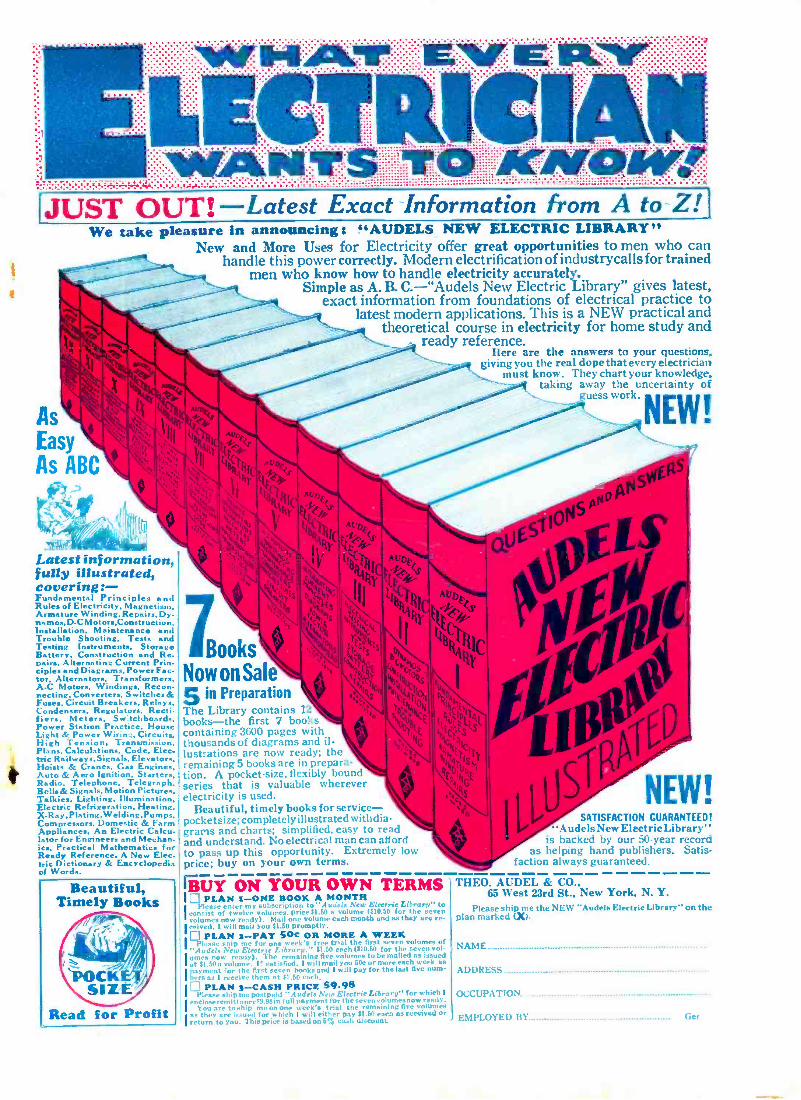
¡JUST OUT! -Latest Exact Information from A to-Z! l We take pleasure in announcing: "AUDELS NEW ELECTRIC LIBRARY"
New and More Uses for Electricity offer great opportunities to men who can handle this power correctly. Modern electrification of industrycalls for trained
men who know how to handle electricity accurately. Simple as A. B. C.-"Audels New Electric ibrary" gives latest,
exact information from foundations of electrical practice to latest modern applications. This is a NEW practical and
theoretical course in electricity for home study and ready reference.
Here are the answers to your questions, giving you the real dope that every electrician
must know. They chart your knowledge, taking away the uncertainty of
As Easy As ABC
uess work,
.. NSWER
Latest information, fully illustrated, covering: - Fundamental Principles nd Rules of Electricity. Magnetism, Armature Winding, Repairs. Dy. namo., D.0 Mot on,Construction, Installation. Maintenance nd Trouble Shooting. Tests and Testing Instruments, Storage Battery. Construction and Re- pairs, Alternating Current Prin. ciples and Diagrams. Power Fac- tor. Alternators. Transformers, A -C Motors. Winding.. Recon- necting, Converter.. Switches & Fuses, Circuit Breakers, Relay.. Cond . Regulator.. Recti- fiers. Meters. Sw:tchboards, Power Station Practice. House Light & Power Wirinz. Circuits, High Tension. Transmission. Plans. Calculations. Code. Elec. tric Railways, Signals. Elevators, Hoists & Cranes. Gas Engines, Auto & Aero Ignition. Starters. Radio. Telephone. Telegraph. Bells &Signals, Motion Pictures, Talkie.. Lighting, Illumination. Electric Refrigeration. Heating, X -Ray. Plating. W elding. Pum ps, Compressors. Domestic & Farm Appliances. An Electric Calcu- lator for Engineers and Mechan- ics. Practical Mathematics for Ready Reference. A New Elec.
'c Dictionary & Encyclopedia of Words.
Books Now on Sale 5 in Preparation The Library contains lz
books -the first 7 books containing 3600 pages with thousands of diagrams and il- lustrations are now ready; the remaining 5 books are in prepara- tion. A pocket -size, flexibly boon, series that is valuable wherever electricity is used.
Beautiful, timely books for service-- pocketsize; completely illustrated with ti. grams and charts; simplified, easy to rea,'. and understand. No electrical man can a(ol to pass up this opportunity. Extremely low price; buy on your own terms.
,,ATISFACTION GUARANTEED! AudelsNew Electric Library
is backed by our 50 -year record as helping hand publishers. Satis-
faction always guaranteed.
iñ ON YOUR OWN TERMS I LÌ PLAN : -ONE BOOK A MONTH Iconsist
Please enter rlm volumes, susubscription
to "Augcis New Electric Library" price $1.50 a volume 1E10.50 for the Be
volumes now ready). Mad one volume each month and as they are re- ceived, I will mail you $1.50 promptly.
PLAN s -PAY 50c OR MORE A WEER Pl. ase snip me for one week's free trial the first seven volumes of
"Audeis New Electric Library." $1.50 each ($10.50 for the seven vol- umes Ilow remaining
I.. l
volumes or more each
as issued as
payment fur ' - 1 ,:'.I pay for the last five num-
bers as I r PLAN 3 -CASH PRICE $9.98
Plea.- I' -A r.. Is T " Electric Library" for which ch. "]alt payment for thesevenvolumesnowready- eny
o U week's trial the remaining five volumes as they ;, .i 1.ßr ,, óieh I will either pay 51 .50 esch as received or return to you. This price is based on 51; cash discount
THEO. AUDEL & CO., 65 West 23rd St., New York, N. Y.
Please ship me the NEW "Audela Electric Library" on the plan marked (X).
NAME
ADDRESS
OCCUPATION
EMPLOYED BY Ger
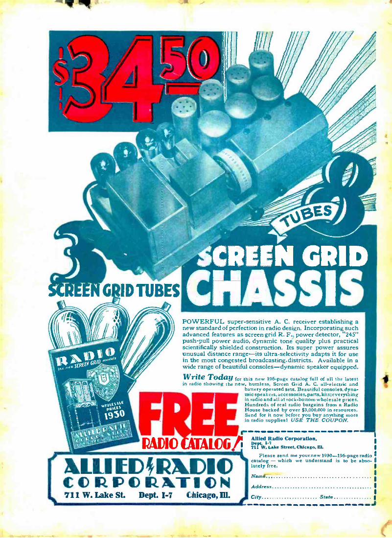
/71(7
SCREEN G
POWERFUL super- sensitive A. C. receiver establishing a new standard of perfection in radio design. Incorporating such advanced features as screen grid R. F., power detector, "245" push -pull power audio, dynamic tone quality plus practical scientifically shielded construction. Its super power assures unusual distance range -its ultra -selectivity adapts it for use in the most congested broadcasting- districts. Available in a wide range of beautiful consoles- dynamic speaker equipped.
Write Today for this new 196 -page catalog full of all the latest in radio showing the new, humless, Screen Grid A. C. all- electric and
battery operated sets. Beautiful consoles, dyna- mic speakers, accessories, parts, kits; everything in radio and all at rock -bottom wholesale prices. Hundreds of real radio bargains from a Radio House backed by over $3,000,000 in resources. Send for it now before you buy anything more in radio supplies! USE THE COUPON. F
RADIO - ,
Radio Corporation, De t. 1 -7 71 W. Lake Street, Chicago, DL
&LLI LLI%CIC CO RDO RATION 711 W. Lake St. Dept. I -7 Chicago, Ill.
Please send me your new 1930 -196 -page radio catalog - which we understand is to be abso- lutely free.
Name
Address
City State J