Embed Size (px)
Citation preview
A Control System for Bionic Shoes
Xunjie Zhang
CMU-RI-TR-17-39
July 2017
School of Computer ScienceCarnegie Mellon University
Pittsburgh, PA 15213
Thesis Committee:Randy Sargent, Chair
Chris AtkesonJennifer Cross
Submitted in partial fulfillment of the requirementsfor the degree of Master of Science in Robotics.
Copyright © 2017 Xunjie Zhang


AbstractThe fact that many residences and businesses lay beyond an easy walking dis-
tance to a public transit stop is known as the ”last mile problem”, and is a barrierto better utilization of a rapid transit network. Alternative modes of transportationincluding bicycles, Segway, scooters, and motorcycles all promise to fill this gap, butnone of them have really solved this problem due to their risky nature or difficulty touse. In this thesis, we present the development of a control system of a pair of bionicshoes that enable average pedestrians to walk twice as fast. The experience is similarto walking on the moving walkway - shoes adapt to your gait thereby making thema natural extension of your legs. In this thesis, we described an interdisciplinary ap-proach through customer development, design thinking and addressing key bipedalwalking challenges.

iv
AcknowledgmentsI would like to thank my advisor Randy Sargent for his advice, constant sup-
port and encouragement. I would like to thank Professor Chris Atkeson and JenniferCross for their inspiration and feedback. I would like to thank my family for theirfinancial and mental support. I would also like to thank Professor Dave Mawhin-ney from Swartz Center for Entrepreneurship for his business advice. I would thankAnand Kapdia from Electrical and Computer Engineering Department for helpingme on firmware and circuits design. I would like to thank Brian Chan, Zulay Olivofrom Tepper school of business and Yubing Zhang from Integrated Innovation Insti-tute on helping to conduct customer discovery and user study. At last, I would thankall of my colleagues at CREATE lab for their support and collaboration.

vi

Contents
1 Introduction 1
2 Customer development 32.1 Hypotheses . . . . . . . . . . . . . . . . . . . . . . . . . . . . . . . . . . . . . 32.2 Customer empathy map . . . . . . . . . . . . . . . . . . . . . . . . . . . . . . . 32.3 User persona . . . . . . . . . . . . . . . . . . . . . . . . . . . . . . . . . . . . 5
2.3.1 A day in the life - before . . . . . . . . . . . . . . . . . . . . . . . . . . 52.3.2 A day in the life - after . . . . . . . . . . . . . . . . . . . . . . . . . . . 5
2.4 Conclusion . . . . . . . . . . . . . . . . . . . . . . . . . . . . . . . . . . . . . 6
3 User centered design 73.1 Key activities . . . . . . . . . . . . . . . . . . . . . . . . . . . . . . . . . . . . 7
3.1.1 Experience description . . . . . . . . . . . . . . . . . . . . . . . . . . . 73.1.2 Expectation description . . . . . . . . . . . . . . . . . . . . . . . . . . . 83.1.3 Usability test . . . . . . . . . . . . . . . . . . . . . . . . . . . . . . . . 9
3.2 System requirements . . . . . . . . . . . . . . . . . . . . . . . . . . . . . . . . 10
4 Physical Hardware 114.1 Related products . . . . . . . . . . . . . . . . . . . . . . . . . . . . . . . . . . 114.2 Design iteration . . . . . . . . . . . . . . . . . . . . . . . . . . . . . . . . . . . 12
5 Gait detection 155.1 Bipedal walking challenge . . . . . . . . . . . . . . . . . . . . . . . . . . . . . 155.2 Gait detection - VMC . . . . . . . . . . . . . . . . . . . . . . . . . . . . . . . . 17
5.2.1 Model . . . . . . . . . . . . . . . . . . . . . . . . . . . . . . . . . . . . 175.2.2 Results . . . . . . . . . . . . . . . . . . . . . . . . . . . . . . . . . . . 185.2.3 Conclusion . . . . . . . . . . . . . . . . . . . . . . . . . . . . . . . . . 19
5.3 Gait detection - SVM . . . . . . . . . . . . . . . . . . . . . . . . . . . . . . . . 205.3.1 Related work . . . . . . . . . . . . . . . . . . . . . . . . . . . . . . . . 205.3.2 Data collection . . . . . . . . . . . . . . . . . . . . . . . . . . . . . . . 205.3.3 Algorithm . . . . . . . . . . . . . . . . . . . . . . . . . . . . . . . . . . 215.3.4 Results . . . . . . . . . . . . . . . . . . . . . . . . . . . . . . . . . . . 22
vii

6 Motor control 256.1 Related work . . . . . . . . . . . . . . . . . . . . . . . . . . . . . . . . . . . . 256.2 Algorithm . . . . . . . . . . . . . . . . . . . . . . . . . . . . . . . . . . . . . . 25
6.2.1 BLDC parameter estimation . . . . . . . . . . . . . . . . . . . . . . . . 266.2.2 Disturbance rejection . . . . . . . . . . . . . . . . . . . . . . . . . . . . 26
6.3 Results . . . . . . . . . . . . . . . . . . . . . . . . . . . . . . . . . . . . . . . . 27
7 Conclusion 31
Bibliography 33
viii

List of Figures
1.1 First/Last mile problem . . . . . . . . . . . . . . . . . . . . . . . . . . . . . . . 11.2 Commuting time vs Rental cost in New York . . . . . . . . . . . . . . . . . . . 11.3 The original prototype . . . . . . . . . . . . . . . . . . . . . . . . . . . . . . . 2
2.1 Nimbus customer empathy map . . . . . . . . . . . . . . . . . . . . . . . . . . 4
3.1 Expectation description . . . . . . . . . . . . . . . . . . . . . . . . . . . . . . . 8
4.1 Rollkers . . . . . . . . . . . . . . . . . . . . . . . . . . . . . . . . . . . . . . . 114.2 Acton Rocket Skates . . . . . . . . . . . . . . . . . . . . . . . . . . . . . . . . 124.3 Prototype Iterations . . . . . . . . . . . . . . . . . . . . . . . . . . . . . . . . . 12
5.1 Gait Cycle and its corresponding GRFs . . . . . . . . . . . . . . . . . . . . . . 155.2 Body COM and COP during walking . . . . . . . . . . . . . . . . . . . . . . . . 165.3 VMC Implementation . . . . . . . . . . . . . . . . . . . . . . . . . . . . . . . . 175.4 State machine used in gait simulation . . . . . . . . . . . . . . . . . . . . . . . 185.5 Simulation results - body pitch angle . . . . . . . . . . . . . . . . . . . . . . . . 185.6 Simulation results - horizontal velocity . . . . . . . . . . . . . . . . . . . . . . . 195.7 Simulation results - body height . . . . . . . . . . . . . . . . . . . . . . . . . . 195.8 Simulation results - vertical ground reaction force . . . . . . . . . . . . . . . . . 195.9 The data collection hardware setting . . . . . . . . . . . . . . . . . . . . . . . . 215.10 Test result of SVM . . . . . . . . . . . . . . . . . . . . . . . . . . . . . . . . . 225.11 Adaboost error plot . . . . . . . . . . . . . . . . . . . . . . . . . . . . . . . . . 23
6.1 Combined feedforward and feedback control scheme . . . . . . . . . . . . . . . 276.2 Measured vs estimated output voltages . . . . . . . . . . . . . . . . . . . . . . . 286.3 Disturbance rejection without feed-forward control . . . . . . . . . . . . . . . . 286.4 Disturbance rejection with feed-forward control . . . . . . . . . . . . . . . . . . 296.5 Swing body induced disturbance . . . . . . . . . . . . . . . . . . . . . . . . . . 29
ix

x

List of Tables
3.1 Commute experience based on modes of transportation . . . . . . . . . . . . . . 8
4.1 Design rationale for each iteration . . . . . . . . . . . . . . . . . . . . . . . . . 13
xi

xii

Chapter 1: Introduction
Approximately 17.5 million daily commuters walk or take public transit in the US, according toMcKenzie [17]. Unfortunately commuting around metro areas is frustrating, slow and expensive.In spite of public transportation being the most time-efficient and affordable choice for mostcommuters, getting to and from the nearest transit stop is still a major barrier for mass commutersto leverage mass transit. The average new yorkers spend over 48 minutes walking as part of theircommute everyday, which is equivalent to 131 hours annually, as show in fig. 1.1. This issue isknown as the first/last mile.
Figure 1.1: First/Last mile problem
One natural solution to the first/last problem is to live closer by the transit stop. However,this solution introduces additional cost on commuters’ rental cost. For instance, commuters inNew York city pays $56 per month more for every minute closer by subway, based on Bialik [3].
Figure 1.2: Commuting time vs Rental cost in New York
1
Alternative modes of transportation including bicycles, Segways, scooters, and motorcyclesall have the potential to help fill this gap, but none of them have really solved the problem wellenough for the average commuters. Bikes are legally required to share roads with vehicles,putting riders in dangerous situation. They are also too large to bring onto most mass transit orcars. Segways do not fit well on sidewalks and also are too large to bring on mass transit orcars. Skateboards and roller skates are unsafe to be on street, and cannot be used on high-densitysidewalks. None of the above can go onto stairs and all have a very steep learning curve.
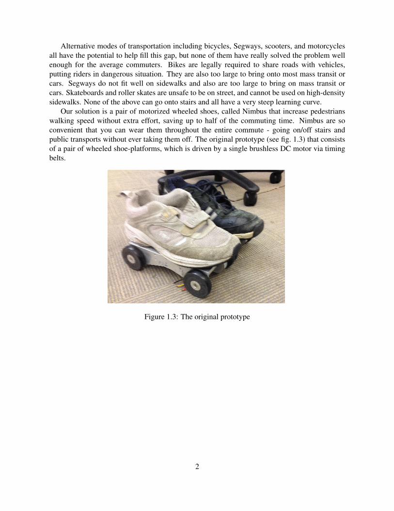
Our solution is a pair of motorized wheeled shoes, called Nimbus that increase pedestrianswalking speed without extra effort, saving up to half of the commuting time. Nimbus are soconvenient that you can wear them throughout the entire commute - going on/off stairs andpublic transports without ever taking them off. The original prototype (see fig. 1.3) that consistsof a pair of wheeled shoe-platforms, which is driven by a single brushless DC motor via timingbelts.
Figure 1.3: The original prototype
2

Chapter 2: Customer development
A lot of developers often fall into the trap of starting with a product idea that they think peoplewant and spend months or even years perfecting the product without understanding customers’needs, which could ultimately lead to a product that no one cares. Therefore, in order to build aproduct that people want, we focus on building a product through validated learning, a conceptfirst described in Ries [23]. The learning process includes validating the first/last mile problemthrough customer discovery, determining and prioritizing the core features to develop throughdesign thinking, and learning from target customers through rapidly shipping engineering itera-tions on a regular interval.
“Should the motorized shoes ever be built?” - This is the most fundamental question that weask ourselves. Moreover, who are our target customers and what is their pain point1? With thosequestions in mind, We worked with MBA students from Tepper School of Business to carry outsurveys on 97 potential users with various commute modes(driving, biking, walking and publictransit), ages between 18 and 35, and annual income ranges between $50K and $150K. We askthem about their preferred commute method, distance and cost of commute, frustration points,which has allowed us to propose and validate a set of hypothesis around customers and their painpoints.
2.1 HypothesesWe came up with three fundamental hypotheses around customers, problem and solution.
• Customers: Cyclists, skateboarder, segway riders, and roller-skate users who commute ona daily basis (for work and recreation).
• Problem: Commuting is time consuming, dangerous, and expensive. The current alterna-tives are difficult to master, not intuitive for first time users, or too bulky to store.
• Solution: Nimbus are incredibly easy to use and enable you to walk twice as fast, arrive atyour destination in less time while costing a fraction of your commute.
2.2 Customer empathy mapWe validated the above hypotheses by conducting structured interviews among a group of 97commuters living in various US cities including Boston, Pittsburgh, New York and San Fran-
1A conceived or real problem that entrepreneurs aim to solve
3
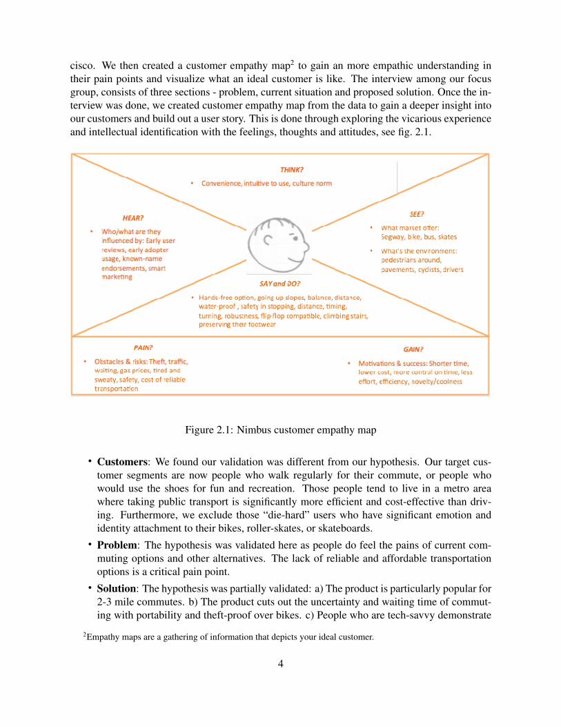
cisco. We then created a customer empathy map2 to gain an more empathic understanding intheir pain points and visualize what an ideal customer is like. The interview among our focusgroup, consists of three sections - problem, current situation and proposed solution. Once the in-terview was done, we created customer empathy map from the data to gain a deeper insight intoour customers and build out a user story. This is done through exploring the vicarious experienceand intellectual identification with the feelings, thoughts and attitudes, see fig. 2.1.
Figure 2.1: Nimbus customer empathy map
• Customers: We found our validation was different from our hypothesis. Our target cus-tomer segments are now people who walk regularly for their commute, or people whowould use the shoes for fun and recreation. Those people tend to live in a metro areawhere taking public transport is significantly more efficient and cost-effective than driv-ing. Furthermore, we exclude those “die-hard” users who have significant emotion andidentity attachment to their bikes, roller-skates, or skateboards.
• Problem: The hypothesis was validated here as people do feel the pains of current com-muting options and other alternatives. The lack of reliable and affordable transportationoptions is a critical pain point.
• Solution: The hypothesis was partially validated: a) The product is particularly popular for2-3 mile commutes. b) The product cuts out the uncertainty and waiting time of commut-ing with portability and theft-proof over bikes. c) People who are tech-savvy demonstrate
2Empathy maps are a gathering of information that depicts your ideal customer.
4

tremendous interests and curiosity towards the product and are willing to invest in a per-sonal robotic technology. d) Many compared it to smart phone and bikes for a price point.e) Those ”die-hard” users were unwilling to see the value proposition over their bikes orskateboards as the augmented walking reduces their exercise and the sense of achievementover mastering a challenging activity. f) An affordable price is also an important factor oncustomers’ purchasing decision.
2.3 User persona
Based on the survey results, we developed a persona to evaluate our solution. Kevin Chan, ayoung software engineer and a city commuters working in the downtown Boston. He starts hiscommute by walking for 20 min to the nearest subway stop, then spends another 10 min on thesubway and completes his commute with another 20 min walk to his office.
2.3.1 A day in the life - before
• Desired outcome Kevin wants to find an alternative to reduce the walking part of hiscommute. As a software developer, he rarely get any exercises during the day. But hevalues staying active and healthy, enjoys being outdoor when the weather is good so thathe can unplug. At the same time, he also want to minimize commuting logistics such aswalking to public transit, need for showering, and changing shoes.
• Attempted approach: He has looked into several alternatives: a) Driving and parking istime-consuming and expensive, b) Biking is possible but vulnerable to theft which is equalto high cost. Biking is also too sweaty and is only allowed on subways during off-peakhours. c) He did a lot of skating when he was a teenager but unfortunately skating involvestoo much physical exertion and is too risky on the busy road.
• Consequence: He has not committed into any of the alternatives and is not happy with thecurrent situation.
2.3.2 A day in the life - after
• New approach: By walking in the motorized shoes to the bus stop, Kevin is able to speedup his walking without extra effort.
• Reward: He now can commute reliably for only 30 minute in total. Not only he can saverecurring bus/subway fee during good weather, but also choose to start commuting withoutworrying about bus schedules and traffic. He loves being outside when the weather is goodand does not worry about theft as the shoes can be easily stored in a backpack or under anoffice desk.
5

2.4 ConclusionThrough customer discovery, we have identified the target customers of Nimbus shoes, validatedthe problem space of first last mile and learned the unique scenarios to apply Nimbus technology.
6

Chapter 3: User centered design
Following the completion of the customer discovery and creation of persona, we next create aset of product requirements that can be translated into a set of engineering specifications. Weconducted a series of co-design activities with the perspective users over three months periodand analyzed their interaction with the original prototype, see fig. 1.3.
A total of 9 interview subjects were chosen from Tepper School of Business as all of themhave worked in large metro areas for at least 6 months. Their demographics include:
• 7 males and 2 females• Ages from 25 to 30• Commuting distance from 1 to 10 miles• Transport modes from driving, walking and bus taking• Income from $75k to $150k
The sample is slightly biased, in that a) all subjects are studying business and are in the sameschool; b) although subjects have lived and commuted in different metropolitan areas in the US,they all only commute to the business school at the time of interview; c) all the subjects havelived in the US all their life.
3.1 Key activities
We have conducted design interviews on two groups of subjects and each interview consistsof three activities - experience description, expectation description and usability tests. Bothinterviews take place in the first three months of the project.
3.1.1 Experience description
In this exercise, each user is asked to describe their commute experience from their home to theworkplace in great details, which include their positive and negative emotions, transportationmode and any particular events or objects of interests.
The following table summarizes users’ commute experience on different modes of transporta-tion. The number in bracket shows the number of interviews responded. Note one subject canrespond with multiple choices. In addition to the cost of transportation, predictability is rankedmore important than cost of time. This is probably because a predictable and reliable commute
7
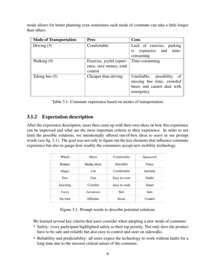
mode allows for better planning even sometimes such mode of commute can take a little longerthan others.
Mode of Transportation Pros ConsDriving (3) Comfortable Lack of exercise, parking
is expensive and time-consuming
Walking (9) Exercise, joyful experi-ence, save money, totalcontrol
Time-consuming
Taking bus (5) Cheaper than driving Unreliable, possibility ofmissing bus time, crowdedbuses and cannot deal withemergency
Table 3.1: Commute experience based on modes of transportation
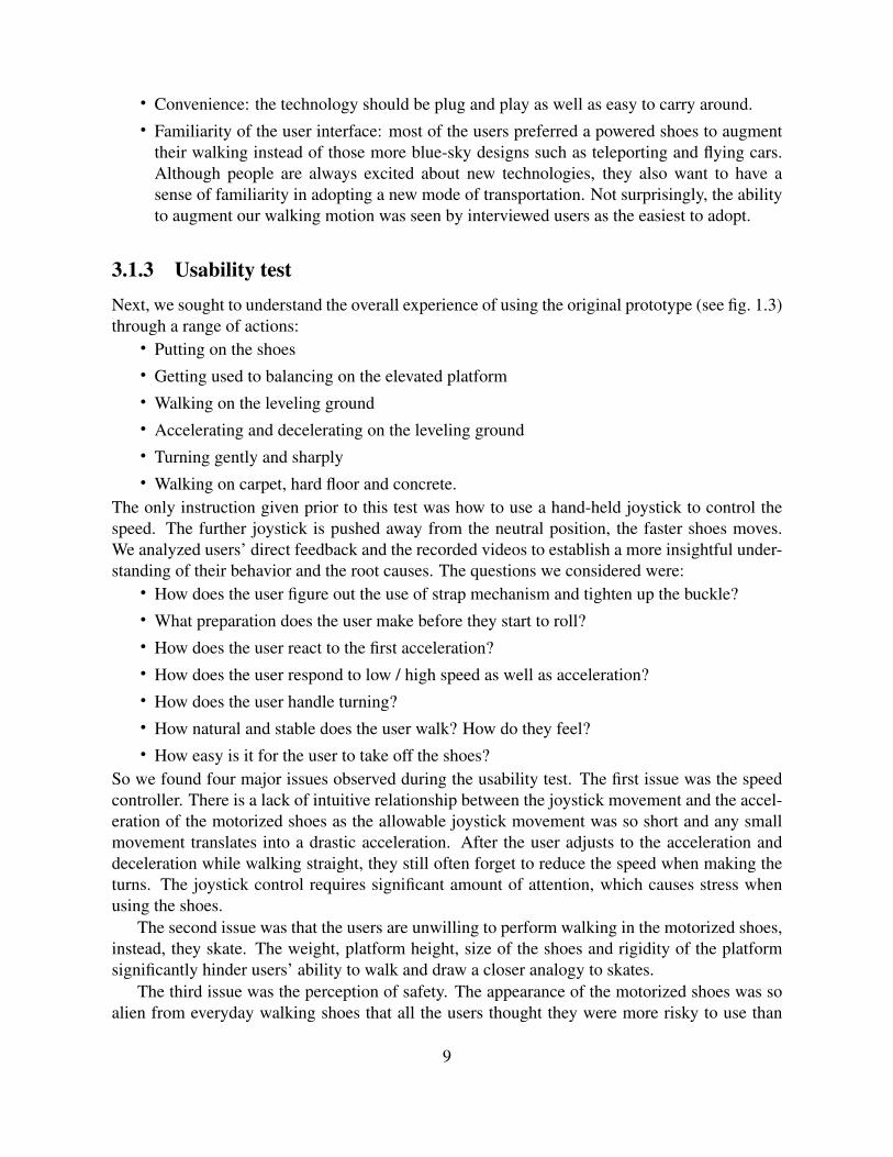
3.1.2 Expectation descriptionAfter the experience description, users then came up with their own ideas on how this experiencecan be improved and what are the most important criteria to their experience. In order to notlimit the possible solutions, we intentionally offered out-of-box ideas to users in our promptwords (see fig. 3.1). The goal was not only to figure out the key elements that influence commuteexperience but also to gauge how readily the consumers accept new mobility technology.
Figure 3.1: Prompt words to describe potential solutions
We learned several key criteria that users consider when adopting a new mode of commute:• Safety: every participant highlighted safety as their top priority. Not only does the product
have to be safe and reliable but also easy to control and steer on sidewalks.• Reliability and predictability: all users expect the technology to work without faults for a
long time due to the mission critical nature of the commute.
8
• Convenience: the technology should be plug and play as well as easy to carry around.• Familiarity of the user interface: most of the users preferred a powered shoes to augment
their walking instead of those more blue-sky designs such as teleporting and flying cars.Although people are always excited about new technologies, they also want to have asense of familiarity in adopting a new mode of transportation. Not surprisingly, the abilityto augment our walking motion was seen by interviewed users as the easiest to adopt.
3.1.3 Usability testNext, we sought to understand the overall experience of using the original prototype (see fig. 1.3)through a range of actions:
• Putting on the shoes• Getting used to balancing on the elevated platform• Walking on the leveling ground• Accelerating and decelerating on the leveling ground• Turning gently and sharply• Walking on carpet, hard floor and concrete.
The only instruction given prior to this test was how to use a hand-held joystick to control thespeed. The further joystick is pushed away from the neutral position, the faster shoes moves.We analyzed users’ direct feedback and the recorded videos to establish a more insightful under-standing of their behavior and the root causes. The questions we considered were:
• How does the user figure out the use of strap mechanism and tighten up the buckle?• What preparation does the user make before they start to roll?• How does the user react to the first acceleration?• How does the user respond to low / high speed as well as acceleration?• How does the user handle turning?• How natural and stable does the user walk? How do they feel?• How easy is it for the user to take off the shoes?
So we found four major issues observed during the usability test. The first issue was the speedcontroller. There is a lack of intuitive relationship between the joystick movement and the accel-eration of the motorized shoes as the allowable joystick movement was so short and any smallmovement translates into a drastic acceleration. After the user adjusts to the acceleration anddeceleration while walking straight, they still often forget to reduce the speed when making theturns. The joystick control requires significant amount of attention, which causes stress whenusing the shoes.
The second issue was that the users are unwilling to perform walking in the motorized shoes,instead, they skate. The weight, platform height, size of the shoes and rigidity of the platformsignificantly hinder users’ ability to walk and draw a closer analogy to skates.
The third issue was the perception of safety. The appearance of the motorized shoes was soalien from everyday walking shoes that all the users thought they were more risky to use than
9

they actually are. There also seem to be a lack of clear instruction to get through the learningcurve as quickly as possible. Many users fail to start walking with the shoes held stationarybefore accelerating the shoes, causing them to lose their balance. This negatively impacts onusers’ initial confidence and experience in adopting to the shoes.
The last issue was about perceiving the device as shoe attachment over actual shoe. It wasclear that users see the device more as a mode of commuting rather than a permanent wearablesthat you have them on all the time. Not only are shoes more personal and cultural but peoplewear shoes to identify themselves. Positioning our device as shoes takes away those benefits.
3.2 System requirementsThrough user centered design, we have seen an opportunity to design beyond motorized shoes.We decided to create a pair of bionic shoes which offer more organic, intuitive and smoothexperience to the users. This will requires a more ergonomic and flexible mechanical design,with an intelligent controller that matches the movement of the device with human motions.Here are the functional and non-functional requirements.
Operational Requirement• The device shall enable the user to walk twice as fast in the most intuitive and natural
fashion.Functional Requirements• The device shall move at a wide range of speeds. (Rationale: the bionic shoes have to be
sufficiently slow for users to adapt initially and fast enough to save up meaningful amountof commute time)
• The device shall provide a set of mechanical structure that allow users to walk naturally.(Rationale: to satisfy safety and convenience expectation)
• The device shall allow users to walk up and down the stairs without taking it off. (Rationa:to satisfy convenience expectation)
• The device shall provide an intuitive means of control that minimize the learning curve.(Ration: to satisfy the expectation of familiar user interface)
Non-functional Requirements• Each shoe should weigh no more than 1kg in total.• The device should be able to fit into an average backpack.
10

Chapter 4: Physical Hardware
4.1 Related products
Chavand [6] developed a walkings device that consists of an upper plate mounted on a chassisresting on a set of four wheels in contact with the ground. The lateral articulation to allownatural movements of the heels with respect to the toes during normal walking. There is also ainterconnected spring mechanism at both the front and rear such that the front extends and therear compresses during the heel-strike and vice versa during the push-off phase. A set of largerwheels on each side of the shoe attempt to provide lateral stability. The pressure sensor underthe front plate is directly proportional to the acceleration which is only activated when the heelis lift off. A small dc motor coupled with a flywheel and a gearbox is used to maintain a setspeed. There are a few issues with this design: a) large wheels on the side of mid-foot areado not provide sufficient stability during push off stage as the most of ground reaction force isconcentrated around ball area; b) accelerating the shoe during the single stance phase means amuch smaller base Of support (BOS) causes walking instability; c) the height of the shoes furtherexacerbate walking instability for walking; d) the flywheel has little use in speed control but onlyadds extra weight.
Figure 4.1: Rollkers
Acton Rocket Skates developed by Treadway et al. [26] are a pair of motorized skates thatuse tilt signal to control the motion. Only the primary skate is installed with a tilting sensor whilethe second skate takes instructions from the primary one. To use the skates, user has to place thesecond skate in front of the primary one and lean back slightly to trigger the tilting sensor. This
11

control method is fundamentally flawed in the way that center of mass (COM) frequently movesahead of base of support (BOS) during bipedal walking motion.
Figure 4.2: Acton Rocket Skates
4.2 Design iterationOur design and manufacture partner helped us to design and construct four major iterations(fromMK1 to MK3), as shown in Figure 4.3 to achieve an optimal trade-off among flexibility, stability,ground clearance and weight. As the focus of this thesis is on the development of the controlsystem, the physical hardware is shown here for context but not described in detail.
Figure 4.3: Prototype Iterations
Table 4.1 explains the major improvement points and drawbacks of each prototype iteration.
12
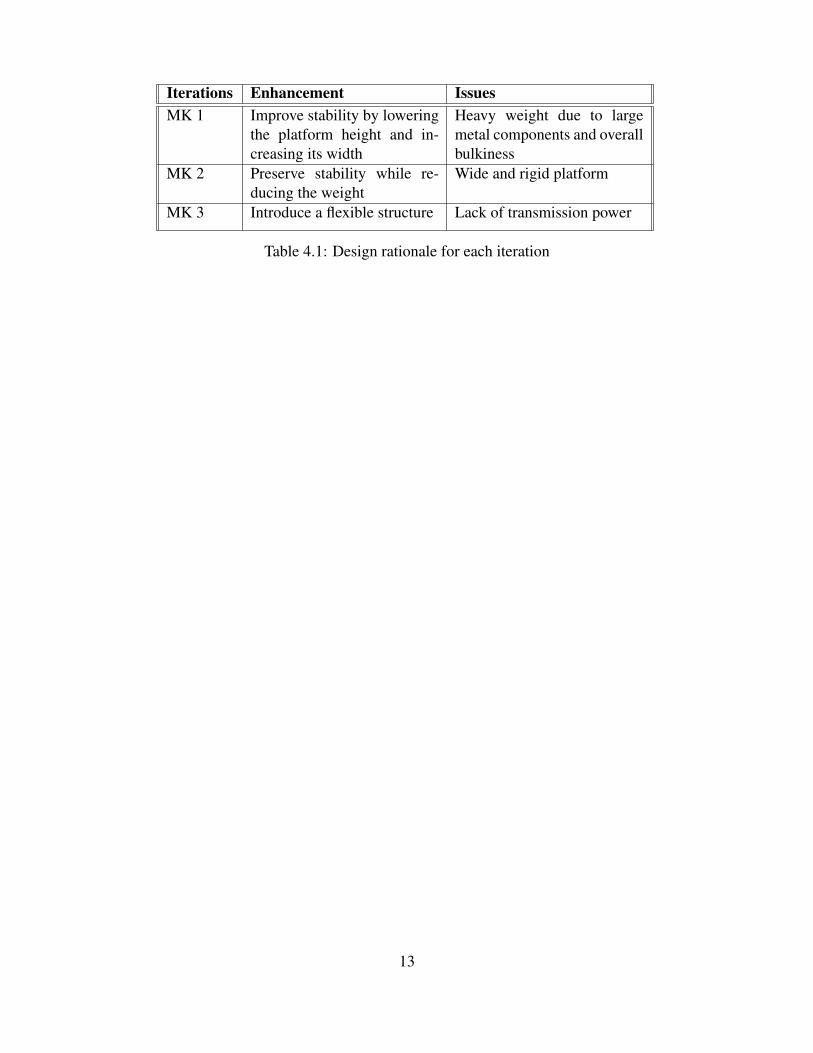
Iterations Enhancement IssuesMK 1 Improve stability by lowering
the platform height and in-creasing its width
Heavy weight due to largemetal components and overallbulkiness
MK 2 Preserve stability while re-ducing the weight
Wide and rigid platform
MK 3 Introduce a flexible structure Lack of transmission power
Table 4.1: Design rationale for each iteration
13

14

Chapter 5: Gait detection
5.1 Bipedal walking challengeUnderstanding the gait dynamics is critical to sizing power system and controller design. A gaitcycle consists of two phases: stance (60% of gait cycle) and swing phase (40% of gait cycle).Stance phase starts with the heel strike - this is the moment both vertical and horizontal groundreaction forces (GRF) will start rising to their peak values. The vertical peak GRF gives the maximpact load that the chassis has to withstand without significant distortion, while the negativehorizontal GRF must be less than the max force that the power system can output such that usersdo not slip forward. In the midstance phase, the body begins to move from force absorption atimpact to force propulsion forward, according to Shultz et al. [24]. Push-off phase occurs beforetransitioning into swing phase, resulting in another peak of vertical GRF and a positive horizontalGRF, both of which are the design points of power system as well.
Figure 5.1: Gait Cycle and its corresponding GRFs2(solid line is vertical GRF, dotted line ishorizontal GRF)
There are three main challenges associated with walking balance, as suggested in Winter[28]. The first challenge is to restablize the body center of gravity (COG) when it is far beyondBOS. In order to accelerate our body in a forward direction, the body has to accelerate the COGahead of BOS, while during the heel strike phase, COG must return within the base of support.As seen in fig. 5.2, since COG is so far off from the support base during acceleration, both hip
2Image Courtesy of Cuccurullo [8]
15
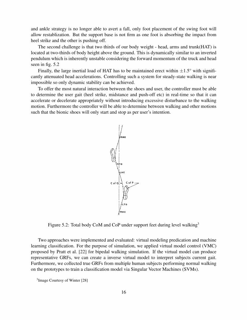
and ankle strategy is no longer able to avert a fall, only foot placement of the swing foot willallow restablization. But the support base is not firm as one foot is absorbing the impact fromheel strike and the other is pushing off.
The second challenge is that two thirds of our body weight - head, arms and trunk(HAT) islocated at two-thirds of body height above the ground. This is dynamically similar to an invertedpendulum which is inherently unstable considering the forward momentum of the truck and headseen in fig. 5.2
Finally, the large inertial load of HAT has to be maintained erect within ±1.5° with signifi-cantly attenuated head accelerations. Controlling such a system for steady-state walking is nearimpossible so only dynamic stability can be achieved.
To offer the most natural interaction between the shoes and user, the controller must be ableto determine the user gait (heel strike, midstance and push-off etc) in real-time so that it canaccelerate or decelerate appropriately without introducing excessive disturbance to the walkingmotion. Furthermore the controller will be able to determine between walking and other motionssuch that the bionic shoes will only start and stop as per user’s intention.
Figure 5.2: Total body CoM and CoP under support feet during level walking3
Two approaches were implemented and evaluated: virtual modeling predication and machinelearning classification. For the purpose of simulation, we applied virtual model control (VMC)proposed by Pratt et al. [22] for bipedal walking simulation. If the virtual model can producerepresentative GRFs, we can create a inverse virtual model to interpret subjects current gait.Furthermore, we collected true GRFs from multiple human subjects performing normal walkingon the prototypes to train a classification model via Singular Vector Machines (SVMs).
3Image Courtesy of Winter [28]
16

5.2 Gait detection - VMC
Virtual Spring-damper components are attached to the robot in three axes (Z,X,theta). Each com-ponent is responsible for stabilization task in height, pitch or forward velocity using PD control.The term virtual means the calculated torques create the same effects as if the physical compo-nents are connected with the real robot, as shown in fig. 5.3. The component forces are calculatedand converted to joint torques by Jacobian relation. Virtual Spring-damper components are at-tached to the robot in three axes (Z,X,theta), controling the height, pitch and forward velocity asindicated by Hu et al. [11].
Figure 5.3: VMC Implementation 4
5.2.1 Model
The model is separated into three parts: mechanics, controllers and state machine. The walkingmechanics has a trunk with two legs located at the same hip joint location. The ankle joint wasconnected to the planar ground interaction model since we assume the foot as a point (no feetmodel used). Parameters like position, angle, velocity and joint torques are transferred betweenwalking mechanics and controllers. The state machine decides which controller to enable andcorrectly apply torques to actuate joints. There are two single support states and one double sup-port state in this model. Double support is enabled when both legs are contacted with the ground.Single support is enabled when one stance leg is on ground and another leg is in swinging.
Height and pitch control are applied in all states. Velocity control is implemented during thedouble support. Swing leg control is based on the mirror law, which means the angle of swingleg should always duplicate the angle of stance leg. The angle is measured between the lineconnecting ankle to hip and the vertical line. During the entire swing phase the knee is bent tonot drag on the ground. The knee joint’s torque is set to zero when body’s position becomesfurther than a preset distance from the support foot instead of when reach a nominal stride lengthwrote in the paper.
4Image Courtesy of Hu et al. [11]
17
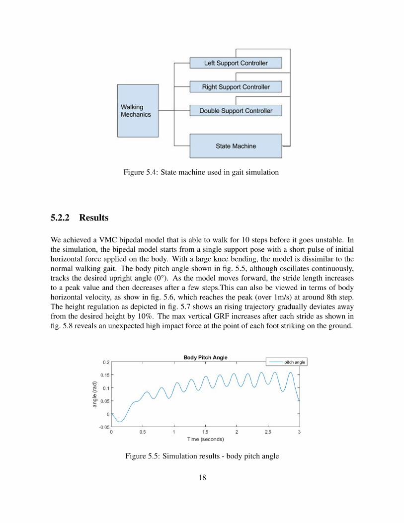
Figure 5.4: State machine used in gait simulation
5.2.2 Results
We achieved a VMC bipedal model that is able to walk for 10 steps before it goes unstable. Inthe simulation, the bipedal model starts from a single support pose with a short pulse of initialhorizontal force applied on the body. With a large knee bending, the model is dissimilar to thenormal walking gait. The body pitch angle shown in fig. 5.5, although oscillates continuously,tracks the desired upright angle (0°). As the model moves forward, the stride length increasesto a peak value and then decreases after a few steps.This can also be viewed in terms of bodyhorizontal velocity, as show in fig. 5.6, which reaches the peak (over 1m/s) at around 8th step.The height regulation as depicted in fig. 5.7 shows an rising trajectory gradually deviates awayfrom the desired height by 10%. The max vertical GRF increases after each stride as shown infig. 5.8 reveals an unexpected high impact force at the point of each foot striking on the ground.
Figure 5.5: Simulation results - body pitch angle
18
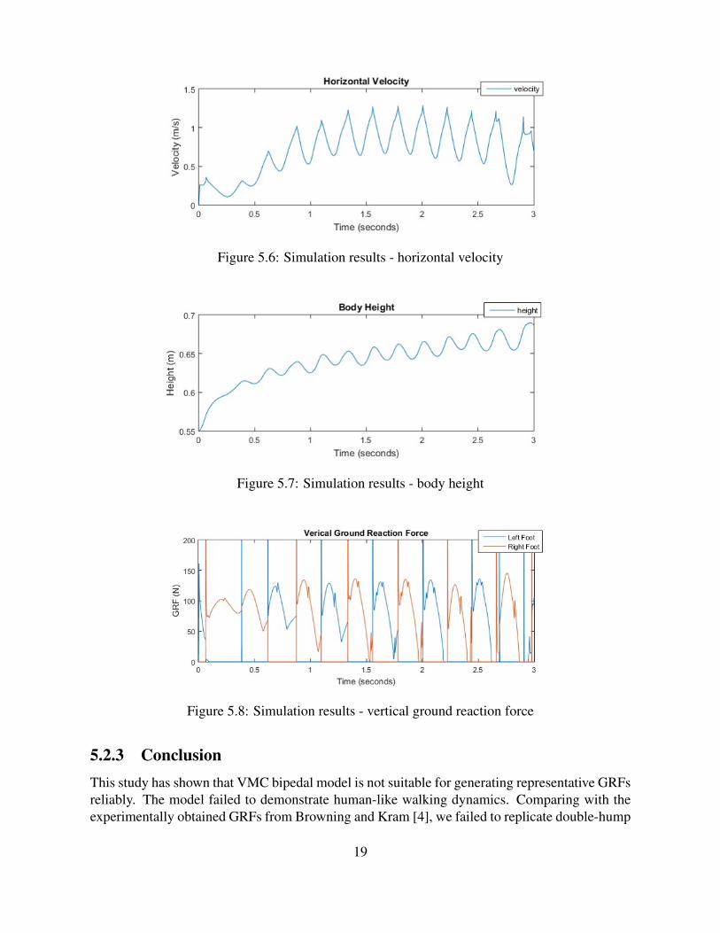
Figure 5.6: Simulation results - horizontal velocity
Figure 5.7: Simulation results - body height
Figure 5.8: Simulation results - vertical ground reaction force
5.2.3 ConclusionThis study has shown that VMC bipedal model is not suitable for generating representative GRFsreliably. The model failed to demonstrate human-like walking dynamics. Comparing with theexperimentally obtained GRFs from Browning and Kram [4], we failed to replicate double-hump
19
pattern of a typical GRF curves. This could have be caused by the incorrect model parameters andgains. However the difficulties of tuning a set of parameters renders the model generated GRFsapproach is less likely to generalize. The high impact force during the initial landing is alsounavoidable due to the rigid segment components. In the future, other models such as adaptiveVMC with flexible parameters and muscle reflex model could be attempted to avoid high impactloss caused by rigid segments. Though the model based approach work for a specific set ofconfigurations, it is not clear if it will be able to model all types of gaits. So we decided to notpursue with the model-based method further.
5.3 Gait detection - SVM
5.3.1 Related workThere are extensive work on gait analysis from clinical literature. Temporal and spatial gaitparameters are obtained and analyzed using machine learning techniques. Zhang et al. [30]use Bayesian classifier to identify healthy walking gait from those with spastic diplegia. Theyused stride length and cadence data collected from children walking experiments. Hundza et al.[12] distinguished people with Parkinson’s disease using gait cycle data measured by InertiaMeasurement Unit (IMU), and achieved 100% accuracy on 13 test subjects. Also, gait cycledetection is done using manually defined heuristic rules. Lee and Grimson [15] use SVM onhuman walking video data to classify individuals.
In robotics community, GRF serves as a key indicator of bipedal walking stability. Vukobra-tovic and Borovac [27] proposed a walking balance criterion based on GRF distribution. Onepopular application in bipedal walking is done by Kajita et al. [13]. In human experiments,Popovic et al. [21], and Cavanagh and Lafortune [5] also shows the correspondence betweenground reaction force and human walking/running state.
To use GRF in gait analysis, Muniz and Nadal [19] applied Principle Component Analysis(PCA) on complete stride GRF data to identify unhealthy gaits. Each sample was the GRF profileof a 10s continuous walking data. Moustakidis et al. [18] pre-processed the GRF data withwavelet packet (WP) for feature selection, then trained a Support Vector Machine (SVM) to dosubject recognition. Muniz et al. [20] evaluate the effectiveness of Parkinson disease treatmentusing typical classifiers including probabilistic neural network, SVM and logistic regression.Alaqtash et al. [1] used artificial neural network and nearest neighbor classifier on 6-axis GRFdata, and achieve 95% accuracy in pathological gait pattern detection.
There are fewer works on real-time gait prediction/classification. Cutler and Davis [9] usedvision data and computer vision technique to detect human walking gait on a treadmill. Skellyand Chizeck [25] used four in-sole force sensitive sensors (FSR) in each shoe with a Fuzzy-logicclassification rule, achieved 86% accuracy on heel-strike/push-off prediction.
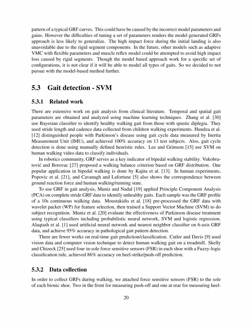
5.3.2 Data collectionIn order to collect GRFs during walking, we attached force sensitive sensors (FSR) to the soleof each bionic shoe. Two in the front for measuring push-off and one at rear for measuring heel-
20
strike. This is illustrated in fig. 5.9. The FSRs are slightly higher than the sole plane, so as tocapture most of the normal contact force. During data collection, the user use a remote controllerto signal his/her intention of walking, which is used as the data label.
Figure 5.9: The data collection hardware setting
5.3.3 Algorithm
A Support Vector Machine is a discriminative classifier with linear decision boundary in thehyperplane. Since the training set is unlikely to be linear, we used th Radius Bias Filter (RBF)kernel to project the training data into hyperplane where linear decision boundary can be drawn.
We took a Fast Fourier Transformation (FFT) on each sensor dataset to obtain the dominantfrequency and the magnitude at the dominant frequency. To express the temporal interdepen-dency between front and back sensors, we subtracted the front sensors from back sensor readingsthen take the magnitude and the phase shift between the peak and trough of each subtractions.
We train the classifier based on both the fast and normal walking gait data, and test theclassifier on varying-speed gait data. F-measure, a measure of testing accuracy, was used toassess the classifiers performance which will be discussed in the Result section.
We used Adaboost (or Ensemble) method has been used on the SVM in attempt to achievean enhanced test performance. The idea is that instead of using a single strong SVM classifier,multiple weak SVM classifiers which are good at different parts of the input space will be trained.We start with a uniformly distributed weights for each training example. Then for each iterationt, we increase the probabilistic weights of each misclassified training example so that the nextlearned classifier can specifically target those points. At the same time, we record the strengthfor each classifier αt. Finally, each weak classifier with their corresponding strength is addedtogether to create a final classifier
H(X) = sign(∑
αtht(X))
21

5.3.4 Results
The result of a single SVM classifier is shown in fig. 5.10, where the first and second subplotsshow all sensory readings on both shoes, while the last subplot shows the correctly predictedlabels (area in green) and incorrectly predicted labels (area in red). This single baseline classifierhas achieved 91.32% accuracy on the test set with 93.43% precision and 89.50% recall, as shownin fig. 5.11. However, the false negative rate is as high as 10.5%, which implies that the classifieris not good at detecting users intention to stop as detecting user start.
Figure 5.10: Test result of SVM
When combining SVM with Adaboost, the test error stagnates at around 9% over 30 iterationswhile the training error shows a marginal improvement as it drops from 0.3% to 0.16%. This islikely due to limitation of window slicing method and SVM classifier incapable of learning thecomplex decision boundary. Overall, SVM has demonstrated an excellent performance for real-time gait classification.
22

Figure 5.11: Adaboost error plot
23

24

Chapter 6: Motor control
It is a challenging task to fit motor, control electronics and transmission system just under thearea of a shoe plus significantly high torque and efficiency requirements. Despite its low costand simple control, a traditional DC motor has insufficient power density and efficiency due toincreasing brush friction at higher speed. In order to address the above issues while keeping thecost low, a hobbyist grade brushless DC (BLDC) motor with a custom control electronics is usedin this project.
Both heel strike and push off phases exert significant disturbance to the BLDC motor whichis controlled at constant speed, causing a significant speed reduction, which is undesirable. Inaddition to the trapezoidal BLDC control, this thesis modifies and implements a disturbance-observer-based control method that was previously used on large permanent-magnet synchronousmotors.
6.1 Related work
In order to reject disturbance for motor control, a feed-forward compensation part could be in-troduced Back and Shim [2], Wu [29]. However, since usually it is impossible to measure thedisturbance directly, it has to be estimated and varied methods have been proposed, such asdisturbance-observer-based (DOB) control method (Chen et al. [7], Ko and Han [14]), and ex-tended state observer (ESO) method (Han [10], Li and Liu [16]). For instance, Chen et al. [7]developed a nonlinear disturbance observer for two link robotic manipulators, Li and Liu [16]used ESO to estimate both states and lumped disturbances simultaneously, and Han [10] pro-posed an active disturbance rejection control by employing a feed-forward compensation basedon ESO.
6.2 Algorithm
Although the low-level computation control using zero-crossing method has shown a satisfactoryresult, the top level speed regulation via PI control is still susceptible to varying load. So thegoal of new motor controller design is to improve its disturbance rejection performance whilemaintaining a relatively low control input. We decided to use a combination of feed-forward andfeedback control to achieve this goal.
25

6.2.1 BLDC parameter estimation
In order to build a feed-forward controller, we first estimate motor parameters. We adopt DCmotor parameter identification based on dynamic parametrization of the motor speed responseunder a constant voltage input. It is more practical and cost effective since it requires only asensorless speed controller which samples motor speed and supplying voltage. The curve fittingperformed by minimizing the sum of the square error via gradient descent.
Consider the following state space representation of DC motor,
d
dt
[θ
i
]=
[− b
JKb
J
−Kt
L −RL
] [θi
]+
[01L
]V
y =[
1 0] [ θ
i
] (6.1)
Where L is the inductivity, i is the winding current, R is the terminal resistance, kb is theback-EMF constant, w is the motor speed, J is the moment of inertia, V is the motor terminalvoltage, b is the rotational damping coefficient, kt is the torque constant, which is an inverse ofkb.
Given terminal voltage and target output, we can derive a gradient descent algorithm (algo-rithm 1) to minimize the sum of the square error between target output and simulated output,#»w ←− argminw
∑l
(yl − f(vl))2, where the threshold is set to be 0.001 between the last and
current iteration error result or 100 iterations.
Algorithm 1 Gradient Descent for updating motor parameters1: l = lth sampled voltage and motor speed2: #»w = [l, R, kb, J, b]
3: while Not Satisfied do4: ∇E = [∂E∂L ,
∂E∂R ,
∂kb∂R ,
∂J∂R ,
∂b∂R ]
5: #»w = #»w − η∇E[ #»w]
6: end while
The combined scheme adds two feed-forward terms in addition to the initial PI controller asshown in fig. 6.1 . The goal is to reduce the overshoot induced by feedback term and improvedisturbance rejection performance.
The inverse BLDC dynamics is approximated as a DC gain which is the ratio of the steadystate velocity of the BLDC motor to its constant voltage input.
DCG = lims→0
G(s) (6.2)
6.2.2 Disturbance rejection
For motor speed regulation applications, especially at the steady state, the periodical disturbancetorque that is caused by foot push-off can cause the speed ripples. If the disturbance can be quan-tified, a voltage can be applied to the motor to counteract the disturbance torque and minimizes
26

Figure 6.1: Combined feedforward and feedback control scheme
the speed ripples as mentioned in Wu [29]. To accomplish this, an on-line estimation of the dis-turbance and a feed-forward control law that generates the counteracting voltage is constructed.The speed response in the Laplace domain is:
w =1kb
tetms2 + tms+ 1(V + Vff )−
tmteJ s+ tm
J
tetms2 + tms+ 1Td (6.3)
Where te = LR
is the electrical time constant and te = RJkbkt
is the mechanical time constant. Herewe will choose Vff to cancel the effect of Td on w which means:
Vff (s) = (L
kts+
R
kt)Td(s) (6.4)
This is then implemented on the hardware in discrete form:
Vff (k) = (L
kt∆t+R
kt)Td(k)− L
kt∆tTd(k − 1) (6.5)
Substitute Td with kt ∗ i (we ignore the inertia term as the moment of inertia is very small and theacceleration signal is extremely noisy and unusable), thus, we can use the following equation tocompute Vff :
Vff (k) = (L
∆t+R)i(k)− L
∆ti(k − 1) (6.6)
6.3 Results
The top plot of Figure 6.2 shows the measured output voltage vs estimated output after gradientdescent while the bottom plot shows the input voltage based on the commanded duty cycle.Several initial conditions have been experimented and the figure represents the smallest sum ofthe squared error.
27

Figure 6.2: The top plot shows the measured output voltage vs estimated output after gradientdescent while the bottom plot shows the input voltage based on the commanded duty cycle
Next we compare the controllers performance by commanding the motor to stabilize 600rpm and observing measured current which is proportional to the disturbance torque that motorexperienced. In 6.3 and 6.4, when both motors are experienced with similar disturbance torque,the conventional PI controller exhibits much larger speed ripples with near 100 percent maxovershoot, while the combined control scheme maintains a much more constant speed with only±16 percent oscillation around the steady state velocity.
Figure 6.3: Disturbance rejection without feed-forward control
28

Figure 6.4: Disturbance rejection with feed-forward control
In order to compare the controllers performance on actual prototype, the combined controlscheme was implemented on the actual shoes. A series of body swinging motions were per-formed to introduce a cyclic disturbance load, as shown in figure 6.5 (note that current is scaledup in the figure to be visualized with speed ripples all together). The combined control schemeis able to maintain a much more stable speed with significantly smaller speed ripples and over-shoots, when compared with the conventional PI controller.
Figure 6.5: Swing body induced disturbance
29

Based on the BLDC motor parameter estimation, we have computed disturbance torque frommeasured current and derived control laws to reject the disturbance. Experimental results in bothbench and prototype tests show that the combined scheme has a superior disturbance rejection,stability and system responsiveness than the conventional PI controller.
30

Chapter 7: Conclusion
In this paper, we have identified the first-last mile challenge as the major barrier to the use ofpublic transport and addressed this challenge by designing a control system of a personal mobilitydevice that enables average pedestrians to double their walking speed. We focused on identifyingthe target customers and their pain point when commuting, breaking down the user pain pointsinto product requirements. Most importantly, by recognizing the technical challenge of bipedalwalking control, we have identified gait predication as the key research question and attemptedtwo approaches: VMC based gait prediction and machine learning based gait classification. Thelatter approach was selected for its performance and ability to generalize in various gaits. Dueto the challenging space constraints and high power throughput requirements, a disturbance-observer-based controller is used to control a BLDC motor as a single power system for eachbionic shoe. In the future, I plan to develop more rigorous customer research to further capturethe user experience and improve upon the technology that addresses those pain points.
31

32
Bibliography
[1] Murad Alaqtash, Thompson Sarkodie-Gyan, Huiying Yu, Olac Fuentes, Richard Brower,and Amr Abdelgawad. Automatic classification of pathological gait patterns using groundreaction forces and machine learning algorithms. In Engineering in Medicine and BiologySociety, EMBC, 2011 Annual International Conference of the IEEE, pages 453–457. IEEE,2011. 5.3.1
[2] Juhoon Back and Hyungbo Shim. Adding robustness to nominal output-feedback con-trollers for uncertain nonlinear systems: A nonlinear version of disturbance observer. Au-tomatica, 44(10):2528–2537, 2008. 6.1
[3] Carl Bialik. New yorkers will pay 56 a month to trim a minute off theircommute. https://fivethirtyeight.com/features/new-yorkers-will-pay-56-a-month-to-trim-a-minute-off-their-commute/, August 2016. 1
[4] Raymond C Browning and Rodger Kram. Effects of obesity on the biomechanics of walk-ing at different speeds. Medicine and Science in Sports and Exercise, 39(9):1632, 2007.5.2.3
[5] Peter R Cavanagh and Mario A Lafortune. Ground reaction forces in distance running.Journal of biomechanics, 13(5):397–406, 1980. 5.3.1
[6] Paul Chavand. Wheeled shoes or undersoles enabling fast walking, May 12 2015. USPatent 9,027,690. 4.1
[7] Wen-Hua Chen, Donald J Ballance, Peter J Gawthrop, Jeremy J Gribble, and John O Reilly.A nonlinear disturbance observer for two link robotic manipulators. In Decision and Con-trol, 1999. Proceedings of the 38th IEEE Conference on, volume 4, pages 3410–3415.IEEE, 1999. 6.1
[8] Sara J Cuccurullo. Physical medicine and rehabilitation board review. Demos MedicalPublishing, 2014. 2
[9] Ross Cutler and Larry S Davis. Robust real-time periodic motion detection, analysis, andapplications. Pattern Analysis and Machine Intelligence, IEEE Transactions on, 22(8):781–796, 2000. 5.3.1
[10] Jingqing Han. From pid to active disturbance rejection control. Industrial Electronics,IEEE transactions on, 56(3):900–906, 2009. 6.1
[11] Jianjuen J Hu, Jerry E Pratt, Chee-Meng Chew, Hugh M Herr, and Gill A Pratt. Virtualmodel based adaptive dynamic control of a biped walking robot. International Journal on
33

Artificial Intelligence Tools, 8(03):337–348, 1999. 5.2, 4
[12] Sandra R Hundza, William R Hook, Christopher R Harris, Sunny V Mahajan, Paul A Leslie,Carl A Spani, Leonhard G Spalteholz, Benjamin J Birch, Drew T Commandeur, and Nigel JLivingston. Accurate and reliable gait cycle detection in parkinson’s disease. Neural Sys-tems and Rehabilitation Engineering, IEEE Transactions on, 22(1):127–137, 2014. 5.3.1
[13] Shuuji Kajita, Fumio Kanehiro, Kenji Kaneko, Kiyoshi Fujiwara, Kensuke Harada,Kazuhito Yokoi, and Hirohisa Hirukawa. Biped walking pattern generation by using pre-view control of zero-moment point. In Robotics and Automation, 2003. Proceedings.ICRA’03. IEEE International Conference on, volume 2, pages 1620–1626. IEEE, 2003.5.3.1
[14] Jong-Sun Ko and Byung-Moon Han. Precision position control of pmsm using neuralnetwork disturbance observer on forced nominal plant. In Mechatronics, 2006 IEEE Inter-national Conference on, pages 316–320. IEEE, 2006. 6.1
[15] Lily Lee and W Eric L Grimson. Gait analysis for recognition and classification. In Auto-matic Face and Gesture Recognition, 2002. Proceedings. Fifth IEEE International Confer-ence on, pages 148–155. IEEE, 2002. 5.3.1
[16] Shihua Li and Zhigang Liu. Adaptive speed control for permanent-magnet synchronousmotor system with variations of load inertia. Industrial Electronics, IEEE Transactions on,56(8):3050–3059, 2009. 6.1
[17] Brian McKenzie. Modes less traveledbicycling and walking to work in the united states:2008–2012. US Census Bureau, New York, 2014. 1
[18] Serafeim P Moustakidis, John B Theocharis, and Giannis Giakas. Subject recognition basedon ground reaction force measurements of gait signals. Systems, Man, and Cybernetics,Part B: Cybernetics, IEEE Transactions on, 38(6):1476–1485, 2008. 5.3.1
[19] AMS Muniz and J Nadal. Application of principal component analysis in vertical groundreaction force to discriminate normal and abnormal gait. Gait & posture, 29(1):31–35,2009. 5.3.1
[20] AMS Muniz, H Liu, KE Lyons, R Pahwa, W Liu, FF Nobre, and J Nadal. Comparisonamong probabilistic neural network, support vector machine and logistic regression forevaluating the effect of subthalamic stimulation in parkinson disease on ground reactionforce during gait. Journal of Biomechanics, 43(4):720–726, 2010. 5.3.1
[21] Marko B Popovic, Ambarish Goswami, and Hugh Herr. Ground reference points in leggedlocomotion: Definitions, biological trajectories and control implications. The InternationalJournal of Robotics Research, 24(12):1013–1032, 2005. 5.3.1
[22] Jerry Pratt, Chee-Meng Chew, Ann Torres, Peter Dilworth, and Gill Pratt. Virtual modelcontrol: An intuitive approach for bipedal locomotion. The International Journal ofRobotics Research, 20(2):129–143, 2001. 5.1
[23] Eric Ries. The lean startup: How today’s entrepreneurs use continuous innovation to createradically successful businesses. Crown Business, 2011. 2
[24] Sandra Shultz, Peggy Houglum, and David Perrin. Examination of Musculoskeletal Injuries
34

with Web Resource. Human Kinetics, 2015. 5.1
[25] Margaret M Skelly and Howard Jay Chizeck. Real-time gait event detection for paraplegicfes walking. Neural Systems and Rehabilitation Engineering, IEEE Transactions on, 9(1):59–68, 2001. 5.3.1
[26] Peter Treadway, Janelle Wang Treadway, and Hang Zheng. Wearable personal transporta-tion system, June 10 2015. US Patent App. 14/736,064. 4.1
[27] Miomir Vukobratovic and Branislav Borovac. Zero-moment pointthirty five years of itslife. International Journal of Humanoid Robotics, 1(01):157–173, 2004. 5.3.1
[28] David A Winter. Human balance and posture control during standing and walking. Gait &posture, 3(4):193–214, 1995. 5.1, 3
[29] Wei Wu. Disturbance compensation for dc motor mechanism low speed regulation: Afeedforward and feedback implementation. In Decision and Control and European ControlConference (CDC-ECC), 2011 50th IEEE Conference on, pages 1614–1619. IEEE, 2011.6.1, 6.2.2
[30] Bai-ling Zhang, Yanchun Zhang, and Rezaul K Begg. Gait classification in children withcerebral palsy by bayesian approach. Pattern Recognition, 42(4):581–586, 2009. 5.3.1
35