Embed Size (px)
Citation preview
International Research Journal of Engineering and Technology (IRJET) e-ISSN: 2395 -0056
Volume: 02 Issue: 05 | Aug-2015 www.irjet.net p-ISSN: 2395-0072
© 2015, IRJET ISO 9001:2008 Certified Journal Page 987
A Control Scheme for Dual Unified Power Quality Conditioner to
Improve Power Quality
K.Karthik1, SK.Mohammad Sadiq2
1 PG Scholar, Department of EEE, JNTU Anantapur, Andhra Pradesh, India 2 PG Scholar, Department of EEE, JNTU Anantapur, Andhra Pradesh, India
---------------------------------------------------------------------***---------------------------------------------------------------------
Abstract- This paper presents a dual three-phase topology of a unified power quality conditioner—iUPQC. The iUPQC is composed of two active filters, a series active filter and a shunt active filter (parallel active filter), used to eliminate harmonics and unbalances. Different from a conventional UPQC, the iUPQC has the series filter controlled as a sinusoidal current source and the shunt filter controlled as a sinusoidal voltage source. Therefore, the pulse width modulation (PWM) controls of the iUPQC deal with a well-known frequency spectrum, since it is controlled using voltage and current sinusoidal references, different from the conventional UPQC that is controlled using non sinusoidal references with the help of fuzzy and PID controller.
Key words—Active filters, control design, fuzzy logic control, power line conditioning, unified power quality conditioner (UPQC).
I. INTRODUCTION
The Usage of power quality conditioners in the distribution system network has increased during the past years due to the steady increase of nonlinear loads connected to the Electrical grid. The current drained by nonlinear loads has a high harmonic content, distorting the voltage at the utility grid and consequently affecting the operation of critical loads. By using a unified power quality conditioner (UPQC) it is possible to ensure a regulated voltage for the loads, balanced and with low harmonic distortion and at the same time draining undistorted currents from the utility grid, even if the grid voltage and the load current have harmonic contents. The UPQC consists of two active filters, the series active filter (SAF) and the shunt or parallel active filter (PAF). The PAF is usually controlled as a non sinusoidal current
source, which is responsible for compensating the
harmonic current of the load, while the SAF is controlled
as a non sinusoidal voltage source, which is responsible
for compensating the grid voltage. Both of them have a
control reference with harmonic contents, and usually,
these references might be obtained through complex
methods. The line conditioner consists of two single-
phase current source inverters where the SAF is
controlled by a current loop and the PAF is controlled by
a voltage loop. In this way, both grid current and load
voltage are sinusoidal, and therefore, their references
are also sinusoidal. The aim of this is to propose dual
three-phase four wire unified power quality conditioner
(iUPQC) by using fuzzy logic in shunt active filter. It is to
be used in the utility grid connection.
Fuzzy logic control methodology has been demonstrated to allow solving uncertain and vague problems. In this paper fuzzy logic controller is used for generation of switching pulses for PWM controllers. The advantages of using fuzzy system are simplicity, ease of application, flexibility, speed and ability to deal with imprecision and uncertainties. Due to absorbing and supplying of active and reactive power in active filter, the capacitance voltage is not maintained constant. In literature many controllers are used for capacitance balancing, such as PI, PID, and fuzzy logic controller. In this paper, fuzzy control algorithm is used to balance the dc voltage of capacitance in order to improve the performance of controller. The proposed method is evaluated and tested under non sinusoidal source voltage conditions using Mat lab/Simulink software. The performance of UPQC depends on the characteristic of the active filters. The fuzzy logic controller is used in almost all sectors of industry and power systems and science and one among them is harmonic current and reactive power compensation.
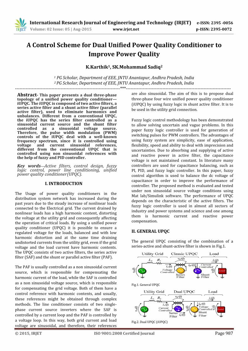
II. GENERAL UPQC The general UPQC consisting of the combination of a series-active and shunt-active filter is shown in Fig.1.
Fig.1. General UPQC
Fig.2. Dual UPQC (iUPQC)
International Research Journal of Engineering and Technology (IRJET) e-ISSN: 2395 -0056
Volume: 02 Issue: 05 | Aug-2015 www.irjet.net p-ISSN: 2395-0072
© 2015, IRJET ISO 9001:2008 Certified Journal Page 988
The general UPQC will be installed at substations by electric power utilities in the near future. The main purpose of the series-active filter is harmonic isolation between a sub transmission system and a distribution system. In addition, the series-active filter has the capability of voltage flicker/imbalance compensation as well as voltage regulation and harmonic compensation at the utility-consumer point of common coupling (PCC). The main purpose of the shunt active filter is to absorb current harmonics, compensate for reactive power and negative-sequence current, and regulate the dc-link voltage between both active filters .In this paper, the integration of the series-active and shunt active filters is called the UPQC.
III. DUAL UPQC WITH FUZZY LOGIC CONTROLLER
The conventional UPQC structure is composed of a SAF and a PAF, as shown in Fig.1. In this configuration, the SAF works as a voltage source in order to compensate the grid distortion, unbalances, and disturbances like sags, swells, and flicker. Therefore, the voltage compensated by the SAF is composed of a fundamental content and the harmonics. The PAF works as a current source and it is responsible for compensating the unbalances, displacement, and harmonics of the load current, ensuring a sinusoidal grid current. The series filter connection to the utility grid is made through a transformer, while the shunt filter is usually connected directly to the load, mainly in low-voltage grid applications. The conventional UPQC has the following drawbacks: complex harmonic extraction of the grid voltage and the load involving complex calculations, voltage and current references with harmonic contents requiring a high bandwidth control, and the leakage inductance of the series connection transformer affecting the voltage compensation generated by the series filter. In order to minimize these drawbacks, the iUPQC is
investigated in this paper, and its scheme is shown in Fig.
2. The scheme of the iUPQC is very similar to the
conventional UPQC, using an association of the SAF and
PAF, diverging only from the way the series and shunt
filters are controlled. In the iUPQC, the SAF works as a
current source, which imposes a sinusoidal input current
synchronized with the grid voltage. The PAF works as a
voltage source imposing sinusoidal load voltage
synchronized with the grid voltage. The SAF acts as high
impedance for the current harmonics and indirectly
compensates the harmonics, unbalances, and
disturbances of the grid voltage since the connection
transformer voltages are equal to the difference between
the grid voltage and the load voltage. In the same way,
the PAF indirectly compensates the unbalances,
displacement, and harmonics of the grid current,
providing a low-impedance path for the harmonic load
current.
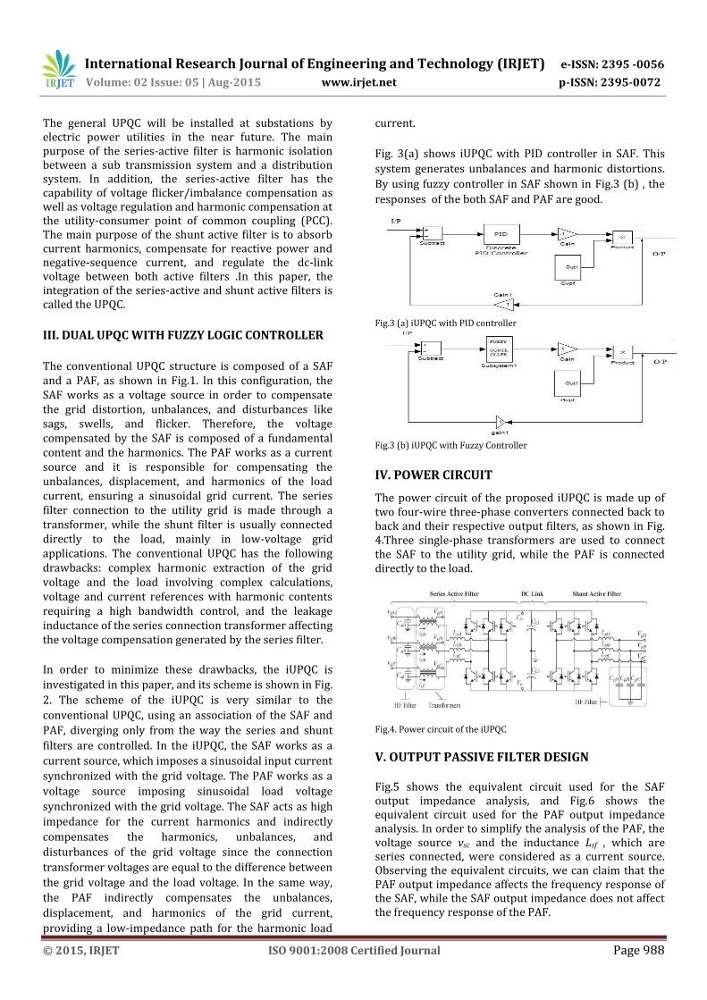
Fig. 3(a) shows iUPQC with PID controller in SAF. This
system generates unbalances and harmonic distortions.
By using fuzzy controller in SAF shown in Fig.3 (b) , the
responses of the both SAF and PAF are good.
Fig.3 (a) iUPQC with PID controller
Fig.3 (b) iUPQC with Fuzzy Controller
IV. POWER CIRCUIT The power circuit of the proposed iUPQC is made up of two four-wire three-phase converters connected back to back and their respective output filters, as shown in Fig. 4.Three single-phase transformers are used to connect the SAF to the utility grid, while the PAF is connected directly to the load.
Fig.4. Power circuit of the iUPQC
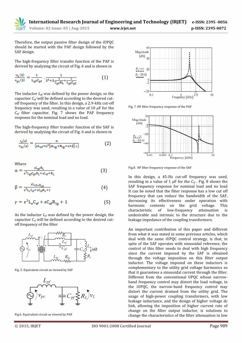
V. OUTPUT PASSIVE FILTER DESIGN Fig.5 shows the equivalent circuit used for the SAF output impedance analysis, and Fig.6 shows the equivalent circuit used for the PAF output impedance analysis. In order to simplify the analysis of the PAF, the voltage source vsc and the inductance Lsf , which are series connected, were considered as a current source. Observing the equivalent circuits, we can claim that the PAF output impedance affects the frequency response of the SAF, while the SAF output impedance does not affect the frequency response of the PAF.
International Research Journal of Engineering and Technology (IRJET) e-ISSN: 2395 -0056
Volume: 02 Issue: 05 | Aug-2015 www.irjet.net p-ISSN: 2395-0072
© 2015, IRJET ISO 9001:2008 Certified Journal Page 989
Therefore, the output passive filter design of the iUPQC should be started with the PAF design followed by the SAF design.
The high-frequency filter transfer function of the PAF is derived by analyzing the circuit of Fig. 6 and is shown in
(1)
The inductor Lpf was defined by the power design, so the capacitor Cpf will be defined according to the desired cut-off frequency of the filter. In this design, a 2.9-kHz cut-off frequency was used, resulting in a value of 10 μF for the Cpf filter capacitor. Fig. 7 shows the PAF frequency response for the nominal load and no load. The high-frequency filter transfer function of the SAF is derived by analyzing the circuit of Fig. 6 and is shown in
(2)
Where
(3)
(4)
(5)
As the inductor Lsf was defined by the power design, the capacitor Csf will be defined according to the desired cut-off frequency of the filter
Fig .5. Equivalent circuit as viewed by SAF
Fig.6. Equivalent circuit as viewed by PAF
Fig. 7. HF filter frequency response of the PAF
Fig.8. HF filter frequency response of the SAF
In this design, a 45-Hz cut-off frequency was used, resulting in a value of 1 μF for the Csf . Fig. 8 shows the SAF frequency response for nominal load and no load It can be noted that the filter response has a low cut off frequency that can reduce the bandwidth of the SAF, decreasing its effectiveness under operation with harmonic contents on the grid voltage. This characteristic of low-frequency attenuation is undesirable and intrinsic to the structure due to the leakage impedance of the coupling transformers. An important contribution of this paper and different from what it was stated in some previous articles, which deal with the same iUPQC control strategy, is that, in spite of the SAF operates with sinusoidal reference, the control of this filter needs to deal with high frequency since the current imposed by the SAF is obtained through the voltage imposition on this filter output inductor. The voltage imposed on these inductors is complementary to the utility grid voltage harmonics so that it guarantees a sinusoidal current through the filter. Different from the conventional UPQC whose narrow-band frequency control may distort the load voltage, in the iUPQC, the narrow-band frequency control may distort the current drained from the utility grid. The usage of high-power coupling transformers, with low leakage inductance, and the design of higher voltage dc link, allowing the imposition of higher current rate of change on the filter output inductor, is solutions to change the characteristics of the filter attenuation in low
International Research Journal of Engineering and Technology (IRJET) e-ISSN: 2395 -0056
Volume: 02 Issue: 05 | Aug-2015 www.irjet.net p-ISSN: 2395-0072
© 2015, IRJET ISO 9001:2008 Certified Journal Page 990
frequencies.
VII. PROPOSED CONTROL SCHEME In the proposed control scheme, the power calculation and harmonic extraction are not needed since the harmonics, unbalances, disturbances, and displacement should be compensated. The SAF has a current loop in order to ensure a sinusoidal grid current synchronized with the grid voltage. The PAF has a voltage loop in order to ensure a balanced regulated load voltage with low harmonic distortion. These control loops are independent from each other since they act independently in each active filter.
A. SAF Control
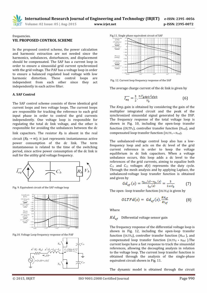
The SAF control scheme consists of three identical grid current loops and two voltage loops. The current loops are responsible for tracking the reference to each grid input phase in order to control the grid currents independently. One voltage loop is responsible for regulating the total dc link voltage, and the other is responsible for avoiding the unbalances between the dc
link capacitors. The resistor Rb is absent in the real
circuit (Rb → ∞); it just represents instantaneous active
power consumption of the dc link. The term instantaneous is related to the time of the switching period, since active power consumption of the dc link is null for the utility grid voltage frequency.
Fig. 9. Equivalent circuit of the SAF voltage loop
Fig.10. Voltage Loop frequency response of the PAF
Fig.11. Single phase equivalent circuit of SAF
Fig. 12. Current loop frequency response of the SAF
The average charge current of the dc link is given by
(6)
The Kmfs gain is obtained by considering the gain of the
multiplier integrated circuit and the peak of the synchronized sinusoidal signal generated by the DSP. The frequency response of the total voltage loop is shown in Fig. 10, including the open-loop transfer
function (OLTFv), controller transfer function (Hvsf), and
compensated loop transfer function (OLTFv + Hvsf). The unbalanced-voltage control loop also has a low-frequency loop and acts on the dc level of the grid current reference in order to keep the voltage equilibrium in dc link capacitors. When a voltage unbalance occurs, this loop adds a dc level to the references of the grid currents, aiming to equalize both CL1 and CL2 voltages d(t) represents the duty cycle. Through the mesh analysis and by applying Laplace, the unbalanced-voltage loop transfer function is obtained and given by
(7)
The open -loop transfer function (OLTFd) is given by
(8)
Where
Differential voltage sensor gain
The frequency response of the differential voltage loop is shown in Fig. 12, including the open-loop transfer
function (OLTFd), controller transfer function (Hdsf ), and
compensated loop transfer function (OLTFd + Hdsf ).The current loops have a fast response to track the sinusoidal references, allowing the decoupling analysis in relation to the voltage loop. The current loop transfer function is obtained through the analysis of the single-phase equivalent circuit shown in Fig. 11.
The dynamic model is obtained through the circuit
International Research Journal of Engineering and Technology (IRJET) e-ISSN: 2395 -0056
Volume: 02 Issue: 05 | Aug-2015 www.irjet.net p-ISSN: 2395-0072
© 2015, IRJET ISO 9001:2008 Certified Journal Page 991
analysis using average values related to the switching period. Under these conditions, the voltages vs(t) and vL(t) are constants. The open loop transfer function ( )
(9)
Where
Kpwmsf is the series filter pulse width modulation
(PWM) modulator gain.
The Kpwmsf gain is equal to the inverse peak value of
the triangular carrier. The frequency response of the
current loop is shown in Fig. 12, including the open-loop
transfer function (OLTFi), controller transfer function
(Hisf), and compensated loop transfer function (OLTFi +
Hisf ).
B. PAF Control The PAF control scheme is formed by three identical load
voltage feedback loops, except for the 120◦ phase
displacements from the references of each other.
The dynamic model is obtained through the circuit analysis
using average values related to the switching period.
Through small signal analysis and by using Laplace, the
voltage loop transfer function is given by
(10)
Where =
The open-loop transfer function ( ) is given by
(11)
Where Kpwmpf is the shunt filter PWM modulator gain.
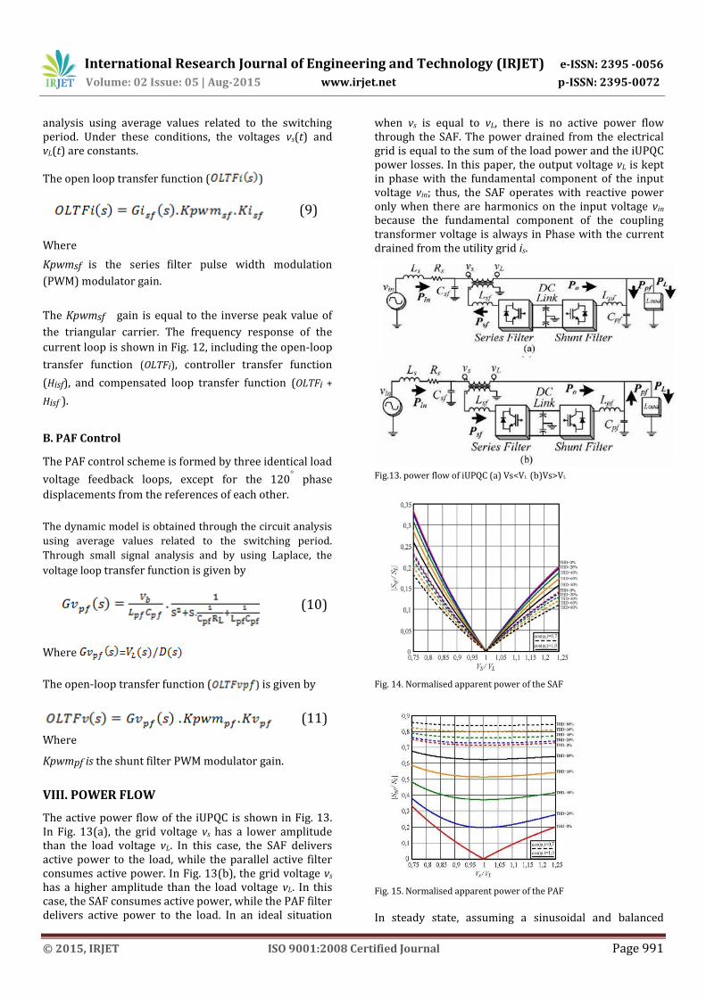
VIII. POWER FLOW The active power flow of the iUPQC is shown in Fig. 13. In Fig. 13(a), the grid voltage vs has a lower amplitude than the load voltage vL. In this case, the SAF delivers active power to the load, while the parallel active filter consumes active power. In Fig. 13(b), the grid voltage vs has a higher amplitude than the load voltage vL. In this case, the SAF consumes active power, while the PAF filter delivers active power to the load. In an ideal situation
when vs is equal to vL, there is no active power flow through the SAF. The power drained from the electrical grid is equal to the sum of the load power and the iUPQC power losses. In this paper, the output voltage vL is kept in phase with the fundamental component of the input voltage vin; thus, the SAF operates with reactive power only when there are harmonics on the input voltage vin because the fundamental component of the coupling transformer voltage is always in Phase with the current drained from the utility grid is.
Fig.13. power flow of iUPQC (a) Vs<VL (b)Vs>VL
Fig. 14. Normalised apparent power of the SAF
Fig. 15. Normalised apparent power of the PAF
In steady state, assuming a sinusoidal and balanced
International Research Journal of Engineering and Technology (IRJET) e-ISSN: 2395 -0056
Volume: 02 Issue: 05 | Aug-2015 www.irjet.net p-ISSN: 2395-0072
© 2015, IRJET ISO 9001:2008 Certified Journal Page 992
utility grid voltage and disregarding the dual UPQC losses, the apparent power of SAF Ssf and PAF Spf normalized in relation to the apparent power of the load respectively, are represented in Figs. 15 and 16.
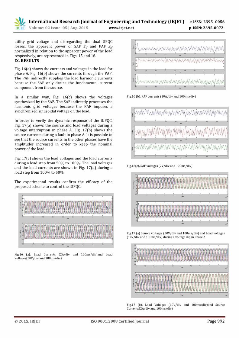
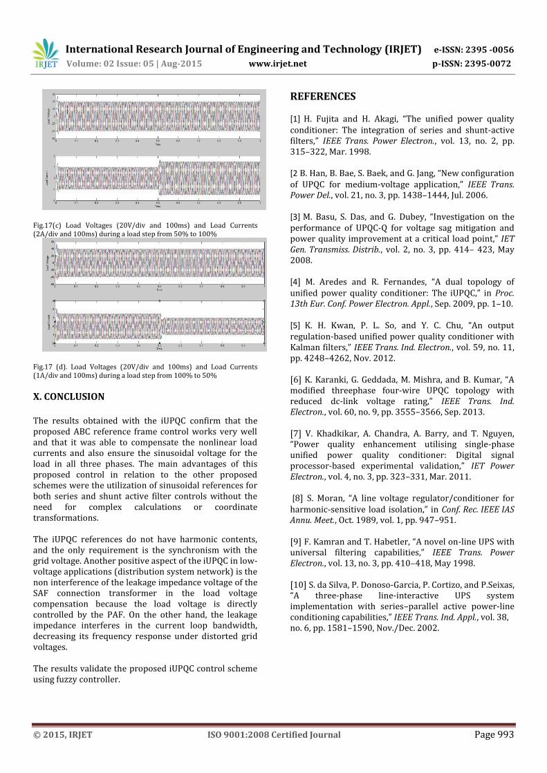
IX. RESULTS Fig. 16(a) shows the currents and voltages in the load for phase A. Fig. 16(b) shows the currents through the PAF. The PAF indirectly supplies the load harmonic currents because the SAF only drains the fundamental current component from the source. In a similar way, Fig. 16(c) shows the voltages synthesized by the SAF. The SAF indirectly processes the harmonic grid voltages because the PAF imposes a synchronized sinusoidal voltage on the load. In order to verify the dynamic response of the iUPQC, Fig. 17(a) shows the source and load voltages during a voltage interruption in phase A. Fig. 17(b) shows the source currents during a fault in phase A. It is possible to see that the source currents in the other phases have the amplitudes increased in order to keep the nominal power of the load. Fig. 17(c) shows the load voltages and the load currents during a load step from 50% to 100%. The load voltages and the load currents are shown in Fig. 17(d) during a load step from 100% to 50%. The experimental results confirm the efficacy of the proposed scheme to control the iUPQC.
Fig.16 (a). Load Currents (2A/div and 100ms/div)and Load Voltages(20V/div and 100ms/div)
Fig.16 (b). PAF currents (10A/div and 100ms/div)
Fig.16(c). SAF voltages (2V/div and 100ms/div)
Fig.17 (a) Source voltages (50V/div and 100ms/div) and Load voltages (10V/div and 100ms/div) during a voltage dip in Phase A
Fig.17 (b). Load Voltages (10V/div and 100ms/div)and Source Currents(2A/div and 100ms/div)
International Research Journal of Engineering and Technology (IRJET) e-ISSN: 2395 -0056
Volume: 02 Issue: 05 | Aug-2015 www.irjet.net p-ISSN: 2395-0072
© 2015, IRJET ISO 9001:2008 Certified Journal Page 993
Fig.17(c) Load Voltages (20V/div and 100ms) and Load Currents (2A/div and 100ms) during a load step from 50% to 100%
Fig.17 (d). Load Voltages (20V/div and 100ms) and Load Currents (1A/div and 100ms) during a load step from 100% to 50%
X. CONCLUSION
The results obtained with the iUPQC confirm that the proposed ABC reference frame control works very well and that it was able to compensate the nonlinear load currents and also ensure the sinusoidal voltage for the load in all three phases. The main advantages of this proposed control in relation to the other proposed schemes were the utilization of sinusoidal references for both series and shunt active filter controls without the need for complex calculations or coordinate transformations. The iUPQC references do not have harmonic contents, and the only requirement is the synchronism with the grid voltage. Another positive aspect of the iUPQC in low-voltage applications (distribution system network) is the non interference of the leakage impedance voltage of the SAF connection transformer in the load voltage compensation because the load voltage is directly controlled by the PAF. On the other hand, the leakage impedance interferes in the current loop bandwidth, decreasing its frequency response under distorted grid voltages. The results validate the proposed iUPQC control scheme using fuzzy controller.
REFERENCES [1] H. Fujita and H. Akagi, “The unified power quality conditioner: The integration of series and shunt-active filters,” IEEE Trans. Power Electron., vol. 13, no. 2, pp. 315–322, Mar. 1998. [2 B. Han, B. Bae, S. Baek, and G. Jang, “New configuration of UPQC for medium-voltage application,” IEEE Trans. Power Del., vol. 21, no. 3, pp. 1438–1444, Jul. 2006. [3] M. Basu, S. Das, and G. Dubey, “Investigation on the performance of UPQC-Q for voltage sag mitigation and power quality improvement at a critical load point,” IET Gen. Transmiss. Distrib., vol. 2, no. 3, pp. 414– 423, May 2008. [4] M. Aredes and R. Fernandes, “A dual topology of unified power quality conditioner: The iUPQC,” in Proc. 13th Eur. Conf. Power Electron. Appl., Sep. 2009, pp. 1–10. [5] K. H. Kwan, P. L. So, and Y. C. Chu, “An output regulation-based unified power quality conditioner with Kalman filters,” IEEE Trans. Ind. Electron., vol. 59, no. 11, pp. 4248–4262, Nov. 2012. [6] K. Karanki, G. Geddada, M. Mishra, and B. Kumar, “A modified threephase four-wire UPQC topology with reduced dc-link voltage rating,” IEEE Trans. Ind. Electron., vol. 60, no. 9, pp. 3555–3566, Sep. 2013. [7] V. Khadkikar, A. Chandra, A. Barry, and T. Nguyen, “Power quality enhancement utilising single-phase unified power quality conditioner: Digital signal processor-based experimental validation,” IET Power Electron., vol. 4, no. 3, pp. 323–331, Mar. 2011. [8] S. Moran, “A line voltage regulator/conditioner for harmonic-sensitive load isolation,” in Conf. Rec. IEEE IAS Annu. Meet., Oct. 1989, vol. 1, pp. 947–951. [9] F. Kamran and T. Habetler, “A novel on-line UPS with universal filtering capabilities,” IEEE Trans. Power Electron., vol. 13, no. 3, pp. 410–418, May 1998. [10] S. da Silva, P. Donoso-Garcia, P. Cortizo, and P.Seixas, “A three-phase line-interactive UPS system implementation with series–parallel active power-line conditioning capabilities,” IEEE Trans. Ind. Appl., vol. 38, no. 6, pp. 1581–1590, Nov./Dec. 2002.

International Research Journal of Engineering and Technology (IRJET) e-ISSN: 2395 -0056
Volume: 02 Issue: 05 | Aug-2015 www.irjet.net p-ISSN: 2395-0072
© 2015, IRJET ISO 9001:2008 Certified Journal Page 994
BIOGRAPHIES
K.KarthiK is currently pursuing his M.Tech Degree in Electrical and Electronics Engineering with the specialization in Control Systems From Jawaharlal Nehru Technological University Anantapur, India. He did his B.tech Degree in Electronics and Communication Engineering from Audisankara college of Engineering and Technology Gudur, India.2012
SK. Mohammad Sadiq is currently pursuing his M.Tech Degree in Electrical and Electronics Engineering with the specialization in Control Systems From Jawaharlal Nehru Technological University Anantapur, India. He did his B.tech Degree in Electrical and Electronics Engineering from Jawaharlal Nehru Technological University, pulivendula, India.2013