Embed Size (px)
Citation preview
A Configurable Reference Modelling Language1
M. Rosemanna, W.M.P. van der Aalstb,a a Centre for Information Technology Innovation, Faculty of Information Technology, Queensland
University of Technology, 126 Margaret Street, Brisbane Qld 4000, Australia, phone: +61 7 3864 9473, fax +61 7 3864 9390, [email protected]
b Faculty of Technology and Management, Eindhoven University of Technology, P.O. Box 513, NL-5600 MB, Eindhoven, The Netherlands, [email protected]
Abstract
Enterprise Systems (ES) are comprehensive off-the-shelf packages that have to be
configured to suit the requirements of an organization. Most ES solutions provide
reference models that describe the functionality and structure of the system. However,
these models do not capture the potential configuration alternatives. This paper discusses
the shortcomings of current reference modelling languages using Event-Driven Process
Chains (EPCs) as an example. We propose Configurable Event-Driven Process Chains
as an extended reference modelling language which allows capturing the core
configuration patterns. A formalization of this language as well as examples for typical
configurations are provided. A program of further research including the identification of
a comprehensive list of configuration patterns, deriving possible notations for reference
model configurations and testing the quality of these proposed extensions in experiments
and focus groups is presented.
Keywords
Reference Model, Enterprise Systems, Configuration, Event-Driven Process Chains
1 This research project is financially supported by SAP Research.
- 2 -
1 Introduction
Enterprise Systems (ES) offer business solutions for typical functional areas such as
procurement, materials management, production, sales and distribution, financial
accounting and human resource management [24, 32]. These functions are typically
individualised for countries and industries, e.g. automotive, retailing, high-tech. Such off-
the-shelf-solutions require configuration before they can be used in the individual context
of an organization.
As an approach to improve the understandability of these systems and to stress the
process-oriented nature of their solutions, ES vendors have developed application
reference models which describe the processes and structure of the system. Enterprise
Systems reference models exist in the form of function, data, system organization, object
and business process models, although the latter are by far the most popular type.
Current reference models, however, are based on conventional modelling languages that
have been developed for the design of enterprise-individual models. Thus, they are not
able to adequately depict possible system configurations. Even further, they don’t provide
decision support regarding the selection of relevant variants. Current application
reference models “just” depict the sum of all possible system capabilities and cannot
sufficiently deal with the requirement of optionality.
This paper contributes to this area by extending an existing process modelling language
used in the by far most successful Enterprise System (SAP) with configurable elements.
Thus, it becomes possible to clearly highlight the required decisions which have to be
made at build-time, i.e. during the individualisation of the generic models.

- 3 -
While our selection of the process modelling language has been driven by its popularity
in the relevant Enterprise Systems modelling practice, the proposed extensions can be
easily adapted to other modelling techniques (e.g. UML or Petri-Nets). Furthermore, we
contribute to the area of Enterprise Systems modelling by providing a comprehensive list
of criteria, which have to be satisfied by configurable process modelling languages.
This paper is structured as follows. The next section provides an overview about the
characteristics of application reference models and gives an example for such a model
(the so-called EPC model) and its current shortcomings. The third section outlines the
research problem and the research methodology. Section four lists the requirements for a
configurable reference modelling technique. Section 5 first formalizes the notion of
Event-Driven Process Chains (EPCs), followed by a presentation of Configurable EPCs
(C-EPCs). This paper ends with a section on related work, a brief summary and a
discussion of the future work.
2 Reference Models
Reference models are generic conceptual models that formalize recommended practices
for a certain domain [16,18]. Often labelled with the term 'best practice' reference models
claim to capture reusable state-of-the-art practices [39,40]. The depicted domains can be
very different and range from selected functional areas such as financial accounting or
Customer Relationship Management to the scope of an entire industry sector, e.g. higher
education.
The main objective of reference models is to streamline the design of enterprise-
individual (particular) models by providing a generic solution. The application of
reference models is motivated by the ‘Design by Reuse’ paradigm. Reference models
- 4 -
accelerate the modelling process by providing a repository of potentially relevant
business processes and structures. These ideally ‘plug and play’ models are also called
Partial Enterprise Models in the terminology of the Generalised Enterprise Reference
Architecture and Methodology (GERAM) [7].
Reference models can be differentiated along the following main criteria
• scope of the model (e.g., functional areas covered)
• granularity of the model (e.g., number of levels of decomposition detail)
• views (e.g., process, data, objects, organization) that are depicted in the model
• degree of integration between the views
• purposes supported
• user groups addressed
• internal or external (commercial) use
• availability of the model (e.g., paper, tool-based, Web-based)
• availability of further textual explanation of the model
• explicit inclusion of alternative business scenarios
• existence of guidelines on how to use these models
• availability of relevant quantitative benchmarking data
A further and more comprehensive differentiation based upon the domain that underlies
the reference model can be found in [6 and 34].
The term reference model is also used for models describing the structure and
functionality of business applications including Enterprise Systems [11]. In these cases, a
reference model can be interpreted as a structured semi-formal description of a particular
application. Application reference models correspond to an existing off-the-shelf-solution
that supports the functionality and structure described in the model. They can be used for
a better understanding and evaluation of the appropriateness of the software.
- 5 -
Furthermore, they aim to facilitate the implementation of the software and can be used for
related end user training [6,20,33].
One of the most comprehensive models is the SAP reference model [11]. Its data model
includes more than 4000 entity types and the reference process models cover more than
1000 business processes and inter-organizational business scenarios. Most of the other
market leading ES vendors have an approach towards such reference models. An
overview of the Baan reference model, for example, is provided in [43]. See also [17] for
reference models in Intentia.
Foundational conceptual work for the SAP reference model had been conducted by
SAP AG and the IDS Scheer AG in a collaborative research project in the years 1990-
1992 [23]. The outcome of this project was the process modelling language Event-Driven
Process Chains (EPCs) [23, 38], which has been used for the design of the reference
process models in SAP. EPCs also became the core modelling language in the
Architecture of Integrated Information Systems (ARIS) [38]. It is now one of the most
popular reference modelling languages and has also been used for the design of many
SAP-independent reference models (e.g., ARIS-based reference model for Siebel CRM or
industry models for banking, retail, insurance, telecommunication, etc.).
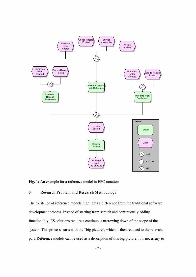
EPCs are directed graphs, which visualise the control flow and consist of events,
functions and connectors. Each EPC starts with at least one event and ends with at least
one event [1, 3, 11, 23, 29, 36, 38]. An event triggers a function, which leads to a new
event. Three types of connectors (AND, Exclusive OR, OR) can be used to model splits
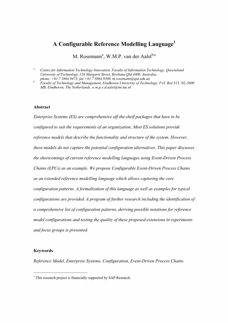
and joins. Figure 1 shows an example for an EPC as it potentially can be found as part of
the SAP reference model. This model shows a part of the invoice verification process.

- 6 -
The EPC contains 10 events, 4 functions, and 4 connectors. The events can be seen as
pre- and/or post-conditions of functions. For example, function Release invoice can be
executed if event Invoice posted is received and the completion of this function will
trigger the event Payment must be effected. There are three functions triggering event
Invoice posted. The exclusive OR connector in the centre of the diagram shows that there
is no need to synchronize these three functions, e.g., the completion of Evaluated Receipt
Settlement directly triggers event Invoice posted. The three other connectors are AND
connectors. Hence, both input events need to be triggered in order to enable function
Evaluated Receipt Settlement.
Figure 1 shows a classical EPC which does not contain any configuration information.
Therefore, valuable information is lacking. For example, it is not shown that Evaluated
Receipt Settlement, i.e. the scenario in which payment for goods is triggered through
goods issue, is only of interest for a subset of all SAP customers. This implies that the
exclusive OR connector may be a choice made at design time for the whole process rather
than at run-time for an individual process instance. It also does not show that Invoicing
Plan Settlement is only relevant, if Evaluated Receipt Settlement is conducted. Note that
because of the exclusive OR connector only one of them is executed but it does not make
any sense to allow for Invoicing Plan Settlement if Evaluated Receipt Settlement is not
allowed. Moreover, the model does not give any insights into the necessity or criticality
of the possible configurations. Thus, the model expressive power is limited and does not
address the possible configurations of the corresponding Enterprise System.
- 7 -
Fig. 1: An example for a reference model in EPC-notation
3 Research Problem and Research Methodology
The existence of reference models highlights a difference from the traditional software
development process. Instead of starting from scratch and continuously adding
functionality, ES solutions require a continuous narrowing down of the scope of the
system. This process starts with the “big picture”, which is then reduced to the relevant
part. Reference models can be used as a description of this big picture. It is necessary to
Goods ReceiptPosted
Serviceis accepted
Invoicereceived
ReleaseInvoice
Invoice Processingwith Reference
Purchaseorder
created
EvaluatedReceipt
Settlement
Invoicing PlanSettlement
Paymentmust
be effected
Goods ReceiptPosted
Purchaseorder
created Goods ReceiptPosted
Purchaseorder
created
Invoiceposted Function
Event
Excl. OR AND
OR
Legend

- 8 -
select the necessary functions and to decide during the configuration process between
alternatives (e.g., reporting in financial accounting or controlling).
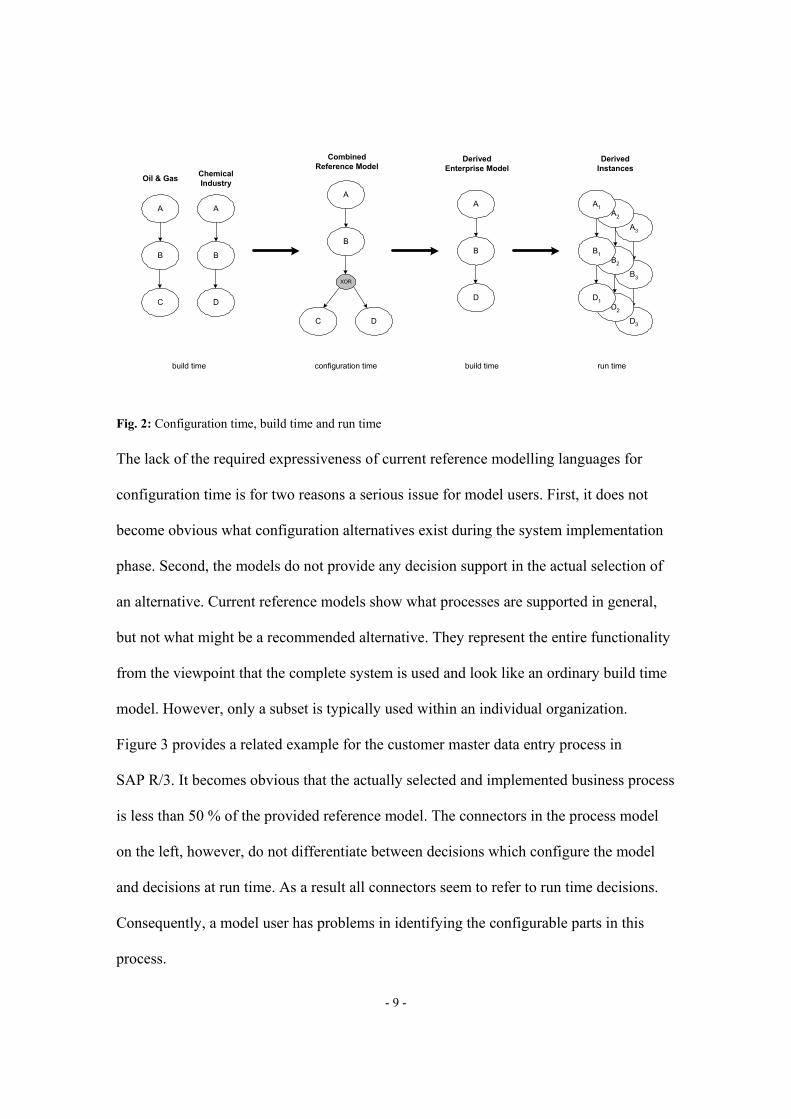
The reference model lifecycle is initiated by the reference model designers, i.e. the
Enterprise Systems vendor. During the design phase available individual conceptual
models are evaluated, selected and consolidated.2 Such a reference model will typically
not only include one proposed alternative, but a range of often mutually exclusive
alternatives. This might be because the depicted scenarios cover different industries or
different countries. At this stage, for example, SAP maintains 27 alternative industry
solutions. However, the current use of traditional modelling languages does not support a
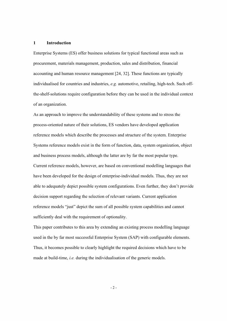
consolidation of these models. Figure 2 demonstrates this problem in a simple example. It
shows the consolidation of corresponding reference models from two different industries.
The XOR split (second from the left) in this case represents a decision point that is of
relevance during the so-called configuration time. A model in this phase cannot
necessarily be executed. It rather captures different alternatives for a domain and has to
be configured before it can serve as the actual build time model for individual process
instances.
2 An organization might also declare the internal best practice in one subsidiary etc. as the internal
benchmark. Thus, an existing conceptual model can have the status of a reference model. This practice can,
for example, be observed in global organizations that roll-out the business blueprint of one location to all
their subsidiaries worldwide. These models are also called prototypical models [7]. They do not require
configurations and are not within the scope of this paper.
- 9 -
Fig. 2: Configuration time, build time and run time
The lack of the required expressiveness of current reference modelling languages for
configuration time is for two reasons a serious issue for model users. First, it does not
become obvious what configuration alternatives exist during the system implementation
phase. Second, the models do not provide any decision support in the actual selection of
an alternative. Current reference models show what processes are supported in general,
but not what might be a recommended alternative. They represent the entire functionality
from the viewpoint that the complete system is used and look like an ordinary build time
model. However, only a subset is typically used within an individual organization.
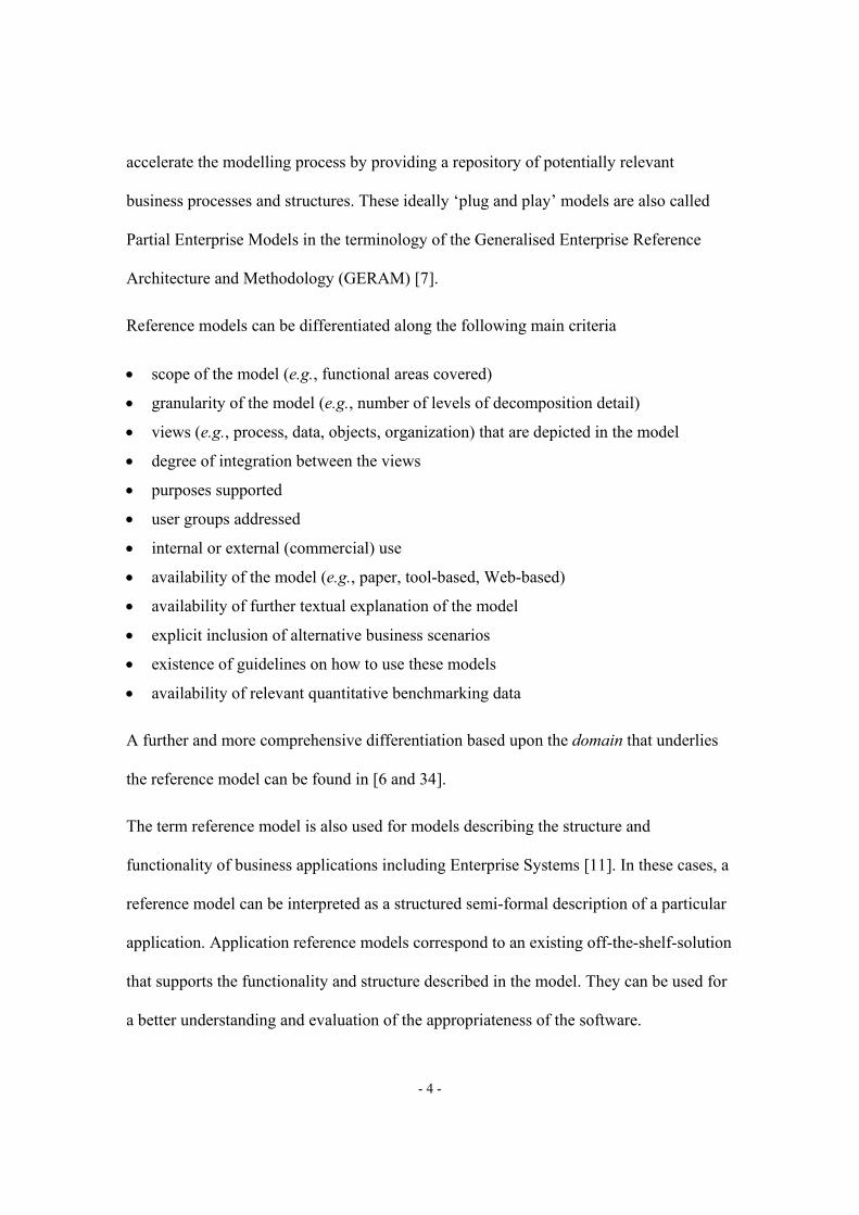
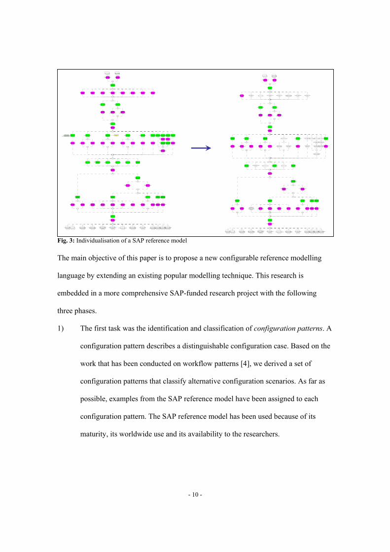
Figure 3 provides a related example for the customer master data entry process in
SAP R/3. It becomes obvious that the actually selected and implemented business process
is less than 50 % of the provided reference model. The connectors in the process model
on the left, however, do not differentiate between decisions which configure the model
and decisions at run time. As a result all connectors seem to refer to run time decisions.
Consequently, a model user has problems in identifying the configurable parts in this
process.
A
B
C
Oil & Gas
A
B
D
ChemicalIndustry
A
B
C D
XOR
CombinedReference Model
A
B
D
A3
B3
D3
A2
B2
D2
A1
B1
D1
DerivedEnterprise Model
DerivedInstances
configuration time build time run timebuild time
- 10 -
Fig. 3: Individualisation of a SAP reference model
The main objective of this paper is to propose a new configurable reference modelling
language by extending an existing popular modelling technique. This research is
embedded in a more comprehensive SAP-funded research project with the following
three phases.
1) The first task was the identification and classification of configuration patterns. A
configuration pattern describes a distinguishable configuration case. Based on the
work that has been conducted on workflow patterns [4], we derived a set of
configuration patterns that classify alternative configuration scenarios. As far as
possible, examples from the SAP reference model have been assigned to each
configuration pattern. The SAP reference model has been used because of its
maturity, its worldwide use and its availability to the researchers.
Conditions processing(Purchasing)
Specify address ofcustomer
Address is specified
Interest calculation isspecified
Plant processing
Maintain accountinginformation
Sold-to party to becreated
Customer is also vendor
Planning group isspecified
Customer-material-infoprocessing [standard]
Maintain account control
Maintain sales data
Ship-to party to becreated
Trading partner isspecified
Clearing betweencustomer/vendor
specified for automaticpayments
Basic data processing forlegal controls [standard]
Management of physicalsamples
Payer to be created
Specify company code
Company code isspecified
Bank details arespecified
Possible paymentmethods are specified
Customer volume rebateagreement processing
[normal]
Customer master recordis to be created
Specify paymenttransaction data
Manual sample release
Determine customerfunction
Invoice recipient is to becreated
Account group withinternal number
assignment determined
Define customer number
Customer number isdetermined
Payment card data ismaintained
Sales area data aremaintained
Maintain paymentinformation
Alternative payerspecific to company
code specified
Create customer
Customer master recordis created
Material listing/exclusion[standard]
Sales personnel isprocessed
Specify account group
Maintain control data
Sample receiver to becreated
Account group withexternal number
assignment determined
Alternative payer forcustomer specified
Line item settlement isspecified
Product allocation [standard]
Specify alternative payer
Maintain messages
Decentralized processingrequired
Customer to be createdfor statistical purposes
Alternative payer foritem allowed
Payment block isspecified
Basic data processing forlegal controls [standard]
Maintain partnerfunctions
Check if decentralizedhandling is desired
Customer is assortmentcustomer
Maintain marketing data
Marketing data aremaintained
Dunning procedure isspecified
Sales deal processing[standard]
Decentralized processingnot required
Maintain dunning data
Customer is one-timecustomer
Determine foreign tradedata
Foreign trade datadetermined
Dunning block isspecified
Customer hierarchyprocessing [standard]
Create unloading point
Maintaincorrespondence
Correspondence ismaintained
Sales summaryprocessing [standard]
Create receiving point
Receiving point has beencreated
Assign receiving point toan unloading point
Customer unloading pntshave been maintained
Maintain creditmanagement data
Credit management datadetermined
Batch search strategyprocessing [standard]
Create department
Department has beencreated
Assign department to areceiving point
Classification [classificationsystem] [standard]
Maintain contactpersons
Contact person data aremaintained
Plant processing Sales Personnelmaster processing
(Tacit) depends onfamiliarity with customers
and interaction with customers
Payment cardSetup
Conditions processing(Purchasing)
Specify address ofcustomer
Address is specified
Interest calculation isspecified
Plant processing
Maintain accountinginformation
Sold-to party to becreated
Customer is also vendor
Planning group isspecified
Customer-material-infoprocessing [standard]
Maintain account control
Maintain sales data
Ship-to party to becreated
Trading partner isspecified
Clearing betweencustomer/vendor
specified for automaticpayments
Basic data processing forlegal controls [standard]
Management of physicalsamples
Payer to be created
Specify company code
Company code isspecified
Bank details arespecified
Possible paymentmethods are specified
Customer volume rebateagreement processing
[normal]
Customer master recordis to be created
Specify paymenttransaction data
Manual sample release
Determine customerfunction
Invoice recipient is to becreated
Account group withinternal number
assignment determined
Define customer number
Customer number isdetermined
Payment card data ismaintained
Sales area data aremaintained
Maintain paymentinformation
Alternative payerspecific to company
code specified
Create customer
Customer master recordis created
Material listing/exclusion[standard]
Sales personnel isprocessed
Specify account group
Maintain control data
Sample receiver to becreated
Account group withexternal number
assignment determined
Alternative payer forcustomer specified
Line item settlement isspecified
Product allocation [standard]
Specify alternative payer
Maintain messages
Decentralized processingrequired
Customer to be createdfor statistical purposes
Alternative payer foritem allowed
Payment block isspecified
Basic data processing forlegal controls [standard]
Maintain partnerfunctions
Check if decentralizedhandling is desired
Customer is assortmentcustomer
Maintain marketing data
Marketing data aremaintained
Dunning procedure isspecified
Sales deal processing[standard]
Decentralized processingnot required
Maintain dunning data
Customer is one-timecustomer
Determine foreign tradedata
Foreign trade datadetermined
Dunning block isspecified
Customer hierarchyprocessing [standard]
Create unloading point
Maintaincorrespondence
Correspondence ismaintained
Sales summaryprocessing [standard]
Create receiving point
Receiving point has beencreated
Assign receiving point toan unloading point
Customer unloading pntshave been maintained
Maintain creditmanagement data
Credit management datadetermined
Batch search strategyprocessing [standard]
Create department
Department has beencreated
Assign department to areceiving point
Classification [classificationsystem] [standard]
Maintain contactpersons
Contact person data aremaintained
Plant processing Sales Personnelmaster processing
- 11 -
2) The next step has been the development and formalization of a new and dedicated
reference modelling language, which supports the specification of these
configuration patterns. This task has been constrained by the desire to rather
extend current reference modelling languages than to develop an entire new
language. This has been motivated by the significant development efforts that
have been invested in reference models already. We selected EPCs as the starting
point for our research due to the popularity of this language for the design of
reference models.
3) The proposed configurable reference modelling language and the corresponding
notation will be rigorously tested in two ways. First, experiments with
experienced business process analysts will be conducted. The selected group of
analysts will be familiar with SAP, process modelling and reference modelling.
These studies will examine the quality and time of comprehension using a
configurable EPC in comparison with current process models. Second, focus
groups with SAP application consultants who are using the SAP reference model
in their consulting practice will be conducted in order to further explore issues
related to the acceptance of the proposed new modelling techniques.
This paper reports on the second phase, i.e. the proposed configurable reference
modelling language. This language is only focused on the so called essential
configurations, i.e. the system variability as it is visible and relevant to the project team,
and not the technical configurations, which subsume aspects related to the technical
realisation [21].

- 12 -
4 Requirements for a configurable reference modelling technique
Reference modelling languages have to be configurable. A configurable modelling
language is characterised by its capability to support decisions at build time, i.e. the
model user can individualise the model by selecting from alternative options before
instances will be derived from it. This means that they should not only capture decisions
on an instance level, but also on a type level. Unlike decisions on an instance level, i.e. at
runtime, decisions on a type level, i.e. at build time, have an impact on the model and its
actual structure. Such configuration decisions have to be clearly differentiated from
runtime decisions and can be highlighted as variation points in a model [21]. A variation
point captures a decision point together with the related possible choices. Furthermore, a
configurable reference modelling language has to consider the following requirements.
a) The language has to support configurations regarding entire processes, functions,
control flow and data.
b) It should be possible to differentiate configuration decisions into mandatory and
optional decisions. Mandatory decisions have to be made before the very first
instance can be derived from this model. The decision could be not to use a
certain variant. Optional decisions can initially be neglected. It should be possible
to maintain defaults for optional configuration decisions. This allows the
instantiation of the model even without explicitly making all possible decisions.
c) Configuration should be differentiated into global and local decisions. Global
decisions are based on the general context and can be made without studying the
individual process model. Such context information includes industry, country,
size etc. The relevant context factors have to be maintained for every variation

- 13 -
point. As soon as information regarding the relevant context has been provided, a
first (hidden or background) configuration of the reference model can take place.
Local configurations require an explicit study of the relevant process model. In
these cases the decision maker has to consider the available individual choices
and make a trade-off decision.
d) Configuration decisions should also be differentiated into critical and non-critical
decisions. Critical decisions have significant impact on the use of the system, can
often not be re-done and should be made by the project team. Non-critical
decisions are of minor importance, can be changed over time and can be made by
individual team members.
e) Configuration decisions can have interrelationships. Any pre-requisites for a
configuration decision should be clearly highlighted. This can include other
decisions, which have to be made before. Moreover, any impact of one decision
on other decisions has to be depicted. This means, a logical order between
configuration decisions has to be considered. This includes interrelationships
within one model, between two process models but also interrelationships
between a reference process model and a related reference data model [35].
f) Configuration decisions can be made on different levels. For example, a first
configuration of the SAP reference model might be an individualization for an
entire global organization. The next level of configuration can be made for a
certain country or business unit.
- 14 -
g) Variation points should refer to further related information within the Enterprise
System. This can include the system online help and the system configuration
module, i.e. in SAP the Implementation Guide. Such information can provide
valuable support for the decision maker.
h) The entire configuration process should also be guided by recommendations or
configuration guidelines. Such information could come as benchmarking data
from the outside of the system if a critical mass of system users is willing to
provide the required data. It can include information such as the processing time
of a given process path, the number of times a decision has been made in the same
industry or the required investments and implementation time for a certain
configuration.
i) Enterprise System reference models are already very comprehensive. Any further
extension of these modelling languages has to carefully consider the impact on the
perceived model complexity.
The following section introduces configurable EPCs as an approach to capture variation
points in a reference process model. At the end of the next section we will reflect on the
requirements identified.
- 15 -
5 Configurable Event-Driven Process Chains (C-EPCs)
Before introducing Configurable EPCs (C-EPCs), we first formalize the notion of the
classical EPC. Then C-EPCs are introduced and formalized followed by a definition of
their semantics and a discussion on partially configured C-EPCs. The section is
concluded by some reflections on the requirements stated in the previous section.
5.1 Formalization of EPCs
In this section, we give a formal definition of an EPC. This definition is based on the
restrictions described in [23] and imposed by tools such as ARIS and SAP R/3 and allows
us to specify the requirements an EPC should satisfy. Note that we need to provide a
formal definition of EPCs to be able to precisely define the notion of configuration we are
after.
Definition 1 [EPC (1)] An Event-Driven Process Chain is a five-tuple (E,F,C,l,A):
- E is a finite (non-empty) set of events, - F is a finite (non-empty) set of functions, - C is a finite set of logical connectors, - l ∈ C → { ∧, XOR, ∨} is a function which maps each connector onto a connector type, - A ⊆ (E ×F) ∪(F ×E) ∪(E ×C) ∪(C ×E) ∪(F ×C) ∪(C ×F) ∪(C ×C) is a set of arcs.
An EPC is composed of three types of nodes: events (E), functions (F) and connectors
(C). Figure 1 shows an EPC containing 10 events, 4 functions and 4 connectors. The type
of each connector is given by the function l: l(c) is the type (∧, XOR, or ∨) of a connector
c ∈ C. Relation A specifies the set of arcs connecting functions, events and connectors.
Definition 1 shows that it is not allowed to have an arc connecting two functions or two
events. There are many more requirements an EPC should satisfy, e.g., only connectors

- 16 -
are allowed to branch, there is at least one start event, there is at least one final event, and
there are several limitations with respect to the use of connectors. To formalize these
requirements we need to define some additional concepts and introduce some notations.
Definition 2 [Directed path, elementary path] Let EPC be an Event-Driven Process Chain. A directed path p from a node n1 to a node nk is a sequence ⟨n1, n2, …, nk ⟩ such that ⟨ni,ni+1 ⟩ ∈ A for 1 ≤ i ≤ k−1.
The definition of directed path will be used to limit the set of routing constructs that may
be used. It also allows for the definition of CEF (the set of connectors on a path from an
event to a function) and CFE (the set of connectors on a path from a function to an event).
CEF and CFE partition the set of connectors C. Based on the function l we also partition C
into C∧, C∨, and CXOR. The sets CJ and CS are used to classify connectors into join
connectors and split connectors.
Definition 3 [N, C∧, C∨, CXOR, •, CJ, CS, CEF, CFE] Let EPC=(E, F, C , l, A) be an Event-Driven Process Chain.
- N = E ∪F ∪C is the set of nodes of EPC. - C∧ = { c ∈ C | l(c) = ∧} - C∨ = { c ∈ C | l(c) = ∨} - CXOR = { c ∈ C | l(c) = XOR } - For n ∈ N: •n = { m | (m,n) ∈ A } is the set of input nodes, and n • = { m | (n,m) ∈ A } is the set of output nodes. - CJ = { c ∈ C | |•c| ≥ 2 } is the set of join connectors. - CS = { c ∈ C | |c•| ≥ 2 } is the set of split connectors. - CEF ⊆ C such that c ∈ CEF if and only if there is a path p = ⟨n1, n2, …, nk−1, nk ⟩ such that n1 ∈ E, n2, …,nk−1 ∈ C, nk ∈ F, and c ∈ { n2, …, nk−1 }. - CFE ⊆ C such that c ∈ CFE if and only if there is a path p = ⟨n1, n2, …, nk−1, nk ⟩ such that n1 ∈ F, n2, …,nk−1 ∈ C, nk ∈ E, and c ∈ { n2, …, nk−1 }. - CEE ⊆ C such that c ∈ CEE if and only if there is a path p = ⟨n1, n2, …, nk−1, nk ⟩ such that n1 ∈ E, n2, …,nk−1 ∈ C, nk ∈ E, and c ∈ { n2, …, nk−1 }. - CFF ⊆ C such that c ∈ CFF if and only if there is a path p = ⟨n1, n2, …, nk−1, nk ⟩ such that n1 ∈ F, n2, …,nk−1 ∈ C, nk ∈ F, and c ∈ { n2, …, nk−1 }.

- 17 -
These notations allow for the definition of syntactical correctness for EPCs.
Definition 4 [EPC (2)] An Event-Driven Process Chain EPC = (E,F,C,l,A) is syntactically correct if and only if the following requirements are satisfied:
- The sets E, F, and C are pairwise disjoint, i.e., E ∩F = ∅, E ∩C = ∅, and F ∩C = ∅. - For each e ∈ E: |•e| ≤ 1 and |e•| ≤ 1. - There is at least one event e ∈ E such that |•e| = 0 (i.e. a start event). - There is at least one event e ∈ E such that |e•| = 0 (i.e. a final event). - For each f ∈ F: |•f| = 1 and |f•| = 1. - For each c ∈ C: |•c| ≥ 1 and |c•| ≥ 1. - CJ and CS partition C, i.e., CJ ∩CS = ∅ and CJ ∪CS = C. - CEE and CFF are empty, i.e., CEE = ∅ are CFF = ∅. - CEF and CFE partition C, i.e., CEF ∩CFE = ∅ and CEF ∪CFE = C.
The first requirement states that each component has a unique identifier (name). Note that
connector names are omitted in the diagram of an EPC. The other requirements
correspond to restrictions on the relation A. Events cannot have multiple input arcs and
there is at least one start event and one final event. Each function has exactly one input
arc and one output arc. A connector c is either a join connector (|c•| = 1 and |•c| ≥ 2) or a
split connector (|•c| = 1 and |c•| ≥ 2). The last requirement states that a connector c is
either on a path from an event to a function or on a path from a function to an event.
Clearly, the EPC shown in Figure 1 satisfies the requirements and is therefore
syntactically correct. In the remainder of this paper we assume all EPCs to be
syntactically correct.
Note that {CJ, CS}, {CEF, CFE}, and {C∧, CXOR, C∨} partition C, i.e., CJ and CS are disjoint
and C = CJ ∪CS, CEF and CFE are disjoint and C = CEF ∪CFE, and C∧, CXOR and C∨ are
pair-wise disjoint and C = C∧ ∪CXOR ∪C∨. In principle there are 2 × 2 × 3 = 12 kinds of
connectors! In the original definition of EPCs [23] two of these 12 constructs are not

- 18 -
allowed: a split connector of type CEF cannot be of type XOR or ∨, i.e., CS ∩CEF ∩CXOR =
∅ and CS ∩CEF ∩C∨ = ∅. As a result of this restriction, there are no choices between
functions sharing the same input event. A choice is resolved after the execution of a
function, not before. In the formalization of EPCs, we will not impose this restriction and
consider CS ∩CEF ∩CXOR = ∅ and CS ∩CEF ∩C∨ = ∅ as a guideline rather than a
requirement.
5.2 On the semantics of EPCs
Definition 4 only provides syntactical requirements and does not make any statements
about the behaviour of the corresponding EPC. For example, one could easily construct
an EPC which contains a deadlock, e.g., in a model an XOR-split connector could split
two flows which are joined using and AND-join connector thus resulting in a deadlock at
runtime. In this paper, we do not consider issues related to the verification of the dynamic
behaviour of EPCs. This is outside the scope of the paper and there is no general
consensus on the semantics of EPCs. When we turn to configurable EPCs we will also
only consider their syntactical correctness and not issues related to their dynamic
behaviour. Nevertheless, we briefly discuss some related work. Since their original
definition in 1992 [23], the semantics of EPCs have often been debated in literature
[1,3,14,25,29,36]. In the original article [23] but also in later work of the authors only an
informal definition of the semantics was given. This triggered many questions. For
example, EPCs allow for OR-joins. Although, the intent of an OR-join connector can
often be derived from the context, its semantics is not clear. Note that an OR-join may
synchronize or not, i.e., it may continue after the first input or wait for more to come. In
fact, in [3] it is shown that no suitable semantics exists for the OR join. These problems
- 19 -
triggered two types of approaches: (1) approaches that provide formal semantics by
mapping EPCs onto a language with formal semantics (e.g., Petri nets) [1,25,29,36] and
(2) approaches that provide a way to refine a given EPC into a model with formal
semantics (e.g., by a designer selecting the desirable behaviour) [14]. In this paper, we
assume only an informal semantics. In fact, we express the semantics of configurable
EPCs in terms of ordinary EPCs. This makes our approach independent of the particular
semantics chosen for EPCs. In other words, any of the formalization approaches
mentioned [1,3,14,25,29,36] can be used as a semantical foundation.
5.3 Configurable EPCs
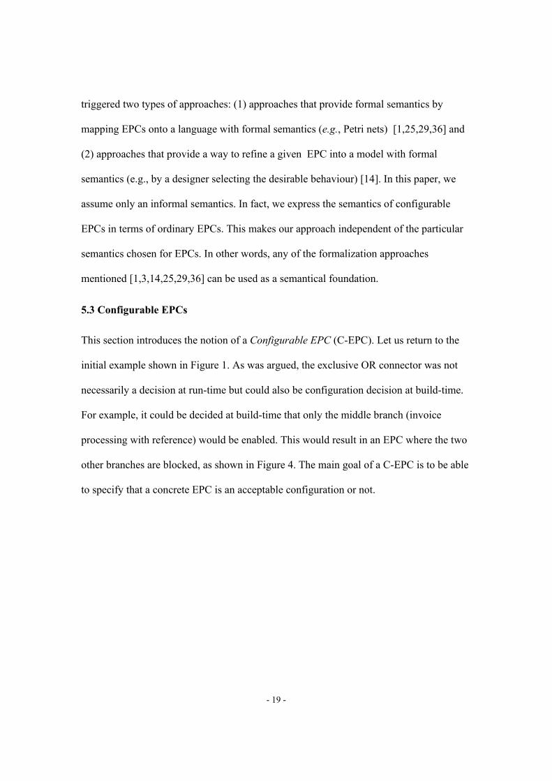
This section introduces the notion of a Configurable EPC (C-EPC). Let us return to the
initial example shown in Figure 1. As was argued, the exclusive OR connector was not
necessarily a decision at run-time but could also be configuration decision at build-time.
For example, it could be decided at build-time that only the middle branch (invoice
processing with reference) would be enabled. This would result in an EPC where the two
other branches are blocked, as shown in Figure 4. The main goal of a C-EPC is to be able
to specify that a concrete EPC is an acceptable configuration or not.
- 20 -
Fig. 4: Example for a model derived from the initial example (Figure 1)
In a C-EPC functions and connectors can be configurable. Configurable functions may be
included (ON), skipped (OFF) or conditionally skipped (OPT). Configurable connectors
may be restricted at build-time time, e.g., a configurable connector of type ∨ may be
mapped onto an ∧ connector. Local configuration choices like skipping a function may be
limited by configuration requirements. For example, if one configurable connector c of
type ∨ is mapped onto an ∧ connector, then another configurable function f needs to be
included. This configuration requirement may be denoted by the logical expression
c=∧⇒ f=ON. To guide the configuration process there is also a partial order suggesting
Goods ReceiptPosted
Serviceis accepted
Invoicereceived
ReleaseInvoice
Invoice Processingwith Reference
Purchaseorder
created
Invoiceposted
EvaluatedReceipt
Settlement
Goods ReceiptPosted
Purchaseorder
created
Invoicing PlanSettlement
Goods ReceiptPosted
Purchaseorder
created
Goods ReceiptPosted
Serviceis accepted
Invoicereceived
ReleaseInvoice
Invoice Processingwith Reference
Purchaseorder
created
Invoiceposted
EvaluatedReceipt
Settlement
Goods ReceiptPosted
Purchaseorder
created
Invoicing PlanSettlement
Goods ReceiptPosted
Purchaseorder
created

- 21 -
the order of configuration. Moreover, besides the configuration requirements there may
also be configuration guidelines. One can think of configuration requirements as hard
constraints and interpret configuration guidelines as soft constraints.
Definition 5 [Configurable EPC] A Configurable EPC (C-EPC) is a ten-tuple (E,F,C,l,A,FC,CC,OC,RC,GC):
- E, F, C, l, and A are as specified in Definition 1 satisfying the constraints mentioned in Definition 4, - FC ⊆ F is the set of configurable functions, - CC ⊆ C is the set of configurable connectors, - OC ⊆ (FC ∪CC) ×(FC ∪CC) is a partial order over the configurable nodes suggesting the order of configuration, - RC is a set of configuration requirements, and - GC is a set of configuration guidelines.
Both RC and GC are sets of logical expressions where the atomic statements bind the configurable nodes to concrete values, e.g., "c=XOR" and "f=ON" where c is a configurable connector and f is a configurable function.
Configurable nodes are denoted by thick circles (for configurable connectors) or thick
rectangles (for configurable functions). Configuration requirements are denoted by dotted
lines connecting the configurable nodes the logical expression refers to and configuration
guidelines are denoted by dashed lines connecting the configurable nodes the logical
expression refers to (see Figure 5). The partial order of configurable nodes OC is not
shown in the example of Figure 5.
A configurable function may be configured as included (ON), skipped (OFF) or
conditionally skipped (OPT). Configurable connectors are mapped onto a concrete choice
for the split or join considered. Clearly, a configurable connector of type ∧ may not be
mapped onto a concrete connector of type ∨. The concrete connector should always
represent a behaviour allowed by the configurable connector, i.e., the configuration
process only restricts the possible execution sequences. In case of a configurable

- 22 -
connector of type XOR or ∨, also only one of the options may be selected, e.g., if a split
connector c has an output function f, then c=SEQf denotes that function f is always
selected.
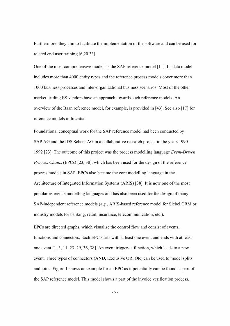
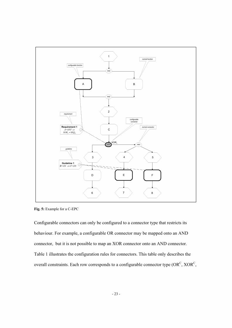
In Figure 5 there are three configurable functions: A, E, and F. Each of these three
functions can be configured as included (ON), skipped (OFF) or conditionally skipped
(OPT). The other three functions cannot be configured, i.e., are always “ON”. There are
four connectors and only the XOR connector is configurable. The configurable XOR
connector can be set to XOR (i.e., a choice at runtime), or select one of the two paths
(i.e., at configuration time the left-hand side or right-hand side is selected). Figure 5 also
shows a requirement and a guideline. The requirement states that if A is configured as
OFF, the path starting with event 3 should no be selected. The guideline states that if E is
configured as ON, then F should also be configured as ON (and visa versa).
- 23 -
Fig. 5: Example for a C-EPC
Configurable connectors can only be configured to a connector type that restricts its
behaviour. For example, a configurable OR connector may be mapped onto an AND
connector, but it is not possible to map an XOR connector onto an AND connector.
Table 1 illustrates the configuration rules for connectors. This table only describes the
overall constraints. Each row corresponds to a configurable connector type (ORC, XORC,
1
A
XOR
3
D
4
E
6 7
5
F
8
AND
B
AND
2
AND
CRequirement 1
A=OFF ⇒XOR1 ≠ SEQ3
XOR1
Guideline 1E=ON ⇔ F=ON
normal connector
configurableconnector
normal function
configurable function
requirement
guideline

- 24 -
ANDC), e.g., an ORC may be mapped onto an OR (∨), XOR, AND (∧), or SEQ (SEQn for
some node n).
OR XOR AND SEQ
ORC X X X X
XORC X X
ANDC X
Table 1: Constraints for the configuration of connectors
To formalize the constraints shown in Table 1 we defined a partial order ≤ C. This partial
order is used to specify which concrete connector type may be used for a given connector
type, i.e., x ≤ C y if and only if a connector of type y may be configured to x (e.g., ∧ ≤ C ∨
but not ∨ ≤ C ∧).
Definition 6 [ ≤ C, CT, CTS] ≤ C defines a partial order on CT = { ∧, XOR, ∨} ∪CTS where CTS={ SEQn | n ∈ E ∪F ∪C}. ≤ C = { (∧,∧), (XOR,XOR), (∨,∨), (XOR,∨), (∧,∨) } ∪{ (n,XOR) | n ∈ CTS} ∪{ (n,∨) | n ∈ CTS} ∪{ (n,n) | n ∈ CTS}.
Note that ≤ C = { (n,n) | n ∈ CT} ∪ (XOR,∨)∪ (∧,∨) ∪ { (n1,n2) | n1 ∈ CTS ∧ n2 ∈ {XOR,∨}}. Recall that this partial order is motivated by the fact that the configurable connector has to subsume the
behaviour of the concrete connector.A configuration maps all configurable nodes onto concrete
values like ON, OFF, and OPT for functions and ∧, XOR, ∨, and SEQn for connectors.
Definition 7 [Configuration] Let CEPC=(E,F,C,l,A,FC,CC,OC,RC,GC) be a C-EPC. lC ∈ (FC → { ON, OFF, OPT }) ∪ (CC → CT) is a configuration of CEPC if for each c ∈ CC:
- lC(c) ≤ C l(c) - if lC(c) ∈ CTS and c ∈ CJ, then there exists an n ∈ •c such that lC(c) = SEQn, - if lC(c) ∈ CTS and c ∈ CS, then there exists an n ∈ c• such that lC(c) = SEQn,
Function lC maps configurable functions onto values like ON, OFF, and OPT, i.e., lC(f) ∈
{ON, OFF, OPT} for f∈ FC. Configurable connectors are mapped onto the set CT, i.e.,

- 25 -
lC(c) ∈ CT for c∈ CC. Clearly this mapping should be consistent with Table 1 and the
partial order ≤ C. Moreover, if lC(c) = SEQn, then n should be in the preset (for a join
connector) or postset (for a split connector) of c.
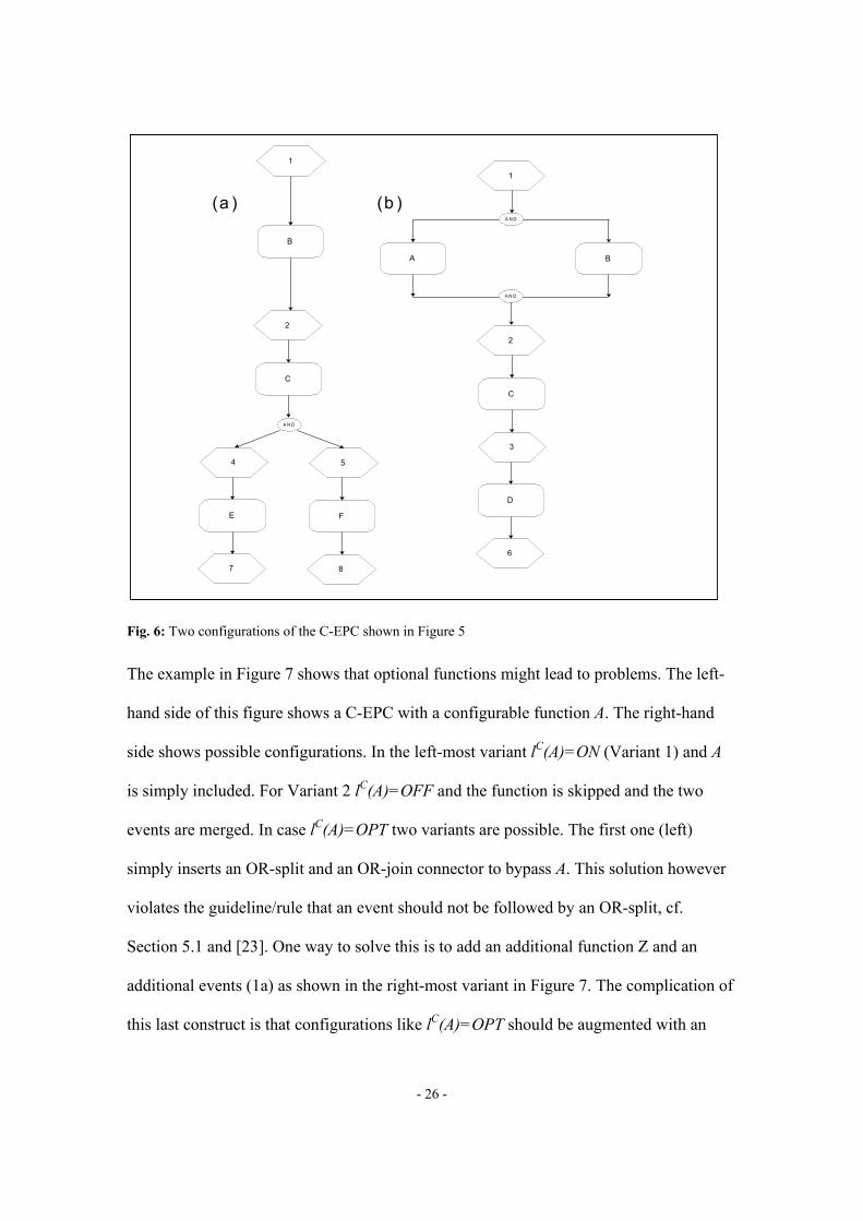
Figure 6 shows two EPCs resulting from a configuration. Consider the EPC shown in
Figure 6(a), i.e., the EPC in the left hand side. If we use the configuration
{(A,OFF),(XOR1,SEQAND3),(E,ON),(F,ON)}, we obtain this EPC. Note that because
function A is not needed, the AND-split and AND-join also were removed. Functions E
and F are both ON thus satisfying the guideline. The requirement shown in Figure 5 is
also satisfied. Since A is skipped, the configurable XOR-split XOR1 could not be set to
SEQ3 without violating this requirement. Figure 6(b), i.e., the EPC in the right hand side,
results from the configuration {(A,ON),(XOR1,SEQ3),(E,OFF),(F,OFF)}. This
configuration specifies that function A is always used and the configurable XOR-split is
set to take only the left path involving function D. The setting of the two remaining
configurable functions (E and F) is not relevant since they are not reachable because of
the configuration of the XOR-split.
- 26 -
Fig. 6: Two configurations of the C-EPC shown in Figure 5
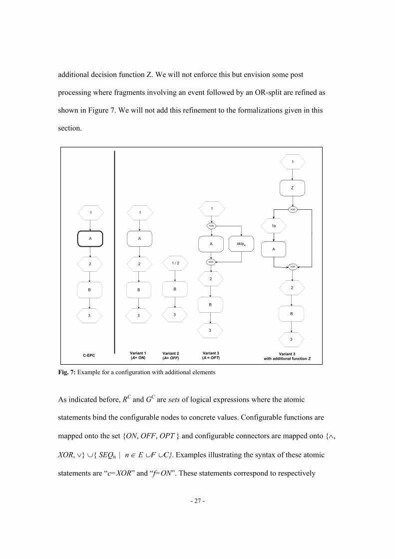
The example in Figure 7 shows that optional functions might lead to problems. The left-
hand side of this figure shows a C-EPC with a configurable function A. The right-hand
side shows possible configurations. In the left-most variant lC(A)=ON (Variant 1) and A
is simply included. For Variant 2 lC(A)=OFF and the function is skipped and the two
events are merged. In case lC(A)=OPT two variants are possible. The first one (left)
simply inserts an OR-split and an OR-join connector to bypass A. This solution however
violates the guideline/rule that an event should not be followed by an OR-split, cf.
Section 5.1 and [23]. One way to solve this is to add an additional function Z and an
additional events (1a) as shown in the right-most variant in Figure 7. The complication of
this last construct is that configurations like lC(A)=OPT should be augmented with an
1
4
E
7
5
F
8
B
2
A N D
C
1
A
3
D
6
A N D
B
A N D
2
C
(a ) (b )
- 27 -
additional decision function Z. We will not enforce this but envision some post
processing where fragments involving an event followed by an OR-split are refined as
shown in Figure 7. We will not add this refinement to the formalizations given in this
section.
Fig. 7: Example for a configuration with additional elements
As indicated before, RC and GC are sets of logical expressions where the atomic
statements bind the configurable nodes to concrete values. Configurable functions are
mapped onto the set {ON, OFF, OPT } and configurable connectors are mapped onto {∧,
XOR, ∨} ∪{ SEQn | n ∈ E ∪F ∪C}. Examples illustrating the syntax of these atomic
statements are “c=XOR” and “f=ON”. These statements correspond to respectively
1
A
2
B
3
XOR
C-EPC Variant 1(A= ON)
Variant 2(A= OFF)
Variant 3with additional function Z
1
A
2
B
3
1 / 2
B
3
1
A
2
B
3
XOR
1a
Z
1
A
2
B
3
XOR
XOR
Variant 3(A = OPT)
skipA

- 28 -
lC(c)=XOR and lC(f)=ON for some configurable connector c and some configurable
function f. Suppose that c1,c2 ∈ CC and f1,f2 ∈ FC. Examples of hard/soft constraints (i.e.,
requirements in RC or guidelines in GC) are: (1) c1=∧⇔ f1=ON ∧f2=ON, (2) f1=ON
∨f2=ON, and (3) c1=∧⇒ c2=∧. Note that in Figure 5 already a requirement (A=OFF⇒
XOR1 ≠ SEQ1) and a guideline (E=ON ⇔ F=ON) have been given.
Configurations may have guidelines and/or requirements that are conflicting, e.g., in
Figure 5 we can add the following two requirements A=OFF ⇔ E=ON and A=OFF
⇔ F=OFF. Clearly there requirements are conflicting with the original guideline. If there
are no conflicting requirements the model is valid. If, in addition, the guidelines are not
conflicting, the configuration is suitable.
Definition 8 [Valid/suitable configuration] Let CEPC=(E,F,C,l,A,FC,CC, OC,RC,GC) be a C-EPC and lC a configuration of CEPC. lC is a valid configuration if it satisfies all configuration requirements, i.e., it satisfies all logical expressions in RC. lC is a suitable configuration if it is valid and it satisfies all configuration guidelines, i.e., it satisfies all logical expressions in RC and GC.
- 29 -
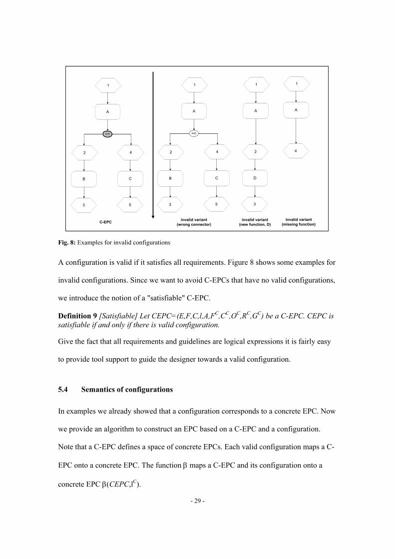
Fig. 8: Examples for invalid configurations
A configuration is valid if it satisfies all requirements. Figure 8 shows some examples for
invalid configurations. Since we want to avoid C-EPCs that have no valid configurations,
we introduce the notion of a "satisfiable" C-EPC.
Definition 9 [Satisfiable] Let CEPC=(E,F,C,l,A,FC,CC,OC,RC,GC) be a C-EPC. CEPC is satisfiable if and only if there is valid configuration.
Give the fact that all requirements and guidelines are logical expressions it is fairly easy
to provide tool support to guide the designer towards a valid configuration.
5.4 Semantics of configurations
In examples we already showed that a configuration corresponds to a concrete EPC. Now
we provide an algorithm to construct an EPC based on a C-EPC and a configuration.
Note that a C-EPC defines a space of concrete EPCs. Each valid configuration maps a C-
EPC onto a concrete EPC. The function β maps a C-EPC and its configuration onto a
concrete EPC β(CEPC,lC).
1
A
XOR
2
B
4
C
3 5
1
A
AND
2
B
4
C
3 5
1
A
2
D
3
1
A
4
C-EPC invalid variant(wrong connector)
invalid variant(new function, D)
invalid variant(missing function)

- 30 -
Definition 10 [β] Let CEPC=(E,F,C,l,A,FC,CC,OC,RC,GC) be a C-EPC and lC a configuration of CEPC. The corresponding EPC β(CEPC,lC) is constructed as follows:
1. EPC1=(E,F,C,l1,A1) with l1 = {(c,l(c)) | c ∈ C\CC} ∪{(c,lC(c)) | c ∈ CC} and A1 = A
\({(c,n) ∈ CS × c• | ∃n′ ∈ c• lC(c)=SEQn′ ∧n ≠ n′} ∪{(n,c) ∈ •c ×CJ | ∃n′ ∈ •c
lC(c)=SEQn′ ∧n ≠ n′}) is the EPC obtained by mapping the configurable connectors
onto their concrete type and removing arcs not involving the selected sequence.3
2. For each f ∈ FC such that lC(f) = OFF, rename the function to skipf to reflect that the
corresponding function is not executed. If •f ∪f• ⊆ E, then merge input and output
event into one, i.e., EPC2=(E2,F2,C,l1,A2) with E2 = (E ∪{e}) \(•f ∪f•), F2 = F\{f},
and A2 = { (n1,n2) ∈ A | {n1,n2}∩(•f ∪f•)=∅} ∪{ (n1,e) | (e1 ∈ •f) ∧(n1,e1) ∈ A} ∪{
(e,n2) | (e2 ∈ f•) ∧(e2,n2) ∈ A} where e is the new connector (no name clashes, i.e., e
∉ N) merging the old input and output connector. Repeat this for each f of this type
and let EPC2 be the resulting EPC.4
3. For each f ∈ FC such that lC(f) = OPT, add function skipf , a split connector splitf, and
a join connector joinf making f optional, i.e., EPC3=(E2,F3,C3,l3,A3) with F3
=F2∪{skipf}, C3 = C∪{splitf,joinf}, l3=l1∪{ (splitf,XOR),(joinf,XOR) }, A3 = { (n1,n2)
∈ A2 | f ∉ {n1,n2}} ∪{(splitf,f),(splitf,skipf),(skipf,joinf),(f,joinf)} ∪{ (n,splitf) | (n,f) ∈
A2} ∪{ (joinf,n) | (f,n) ∈ A2}. Repeat this for each f of this type and let EPC3 be the
resulting EPC.
3 Note that such an EPC may not satisfy all the requirements stated in Definition 4.
4 Note that it is not always possible to remove functions that are connected to a connector since connectors are either on a path from an event to a function or vice versa.

- 31 -
4. Remove all connectors with just one input and one output node, i.e.,
EPC4=(E2,F3,C4,l4,A4) with C4 = {c ∈ C3 | |c•| > 1 ∨ |•c| > 1}, l4 = {(c,x) ∈ l3 | c ∈
C4}, and A4 = { (n1,n2) ∈ A3 | {n1,n2}∩(C3\C4) = ∅} ∪{(n1,n2) | ∃c ∈ C3\C4
{(n1,c),(c,n2)} ∈ A3}.
5. Remove all isolated nodes, i.e., nodes without input and output arcs.
6. Re-apply Step 2 of the algorithm, i.e., try to remove the remaining functions labelled
“skipf”.
7. Remove all nodes not on some path from a start event to a final event. Consider only
start and final events also present in original EPC, i.e., not the new start/final events
that may have been introduced in e.g. Step 1.
8. Re-apply Step 4 of the algorithm, i.e., remove connectors with just one input and one
output node that may have been introduced in Step 7. The resulting EPC is
β(CEPC,lC).
It is easy to verify that the examples given thus far are indeed consistent with the
algorithm. Although Definition 10 suggests that β(CEPC,lC) is indeed an EPC satisfying
the requirements mentioned before, this remains to be proven.
Theorem 1 [β(CEPC,lC) is an EPC] Let CEPC=(E,F,C,l,A,FC,CC,OC,RC,GC) be a C-EPC and lC a configuration of CEPC. β(CEPC,lC) is an EPC satisfying all requirements stated in Definition 4.
Proof.
EPC0=(E,F,C,l,A) satisfies all requirements by definition. Next we check how the
requirements are affected by the seven steps.
- 32 -
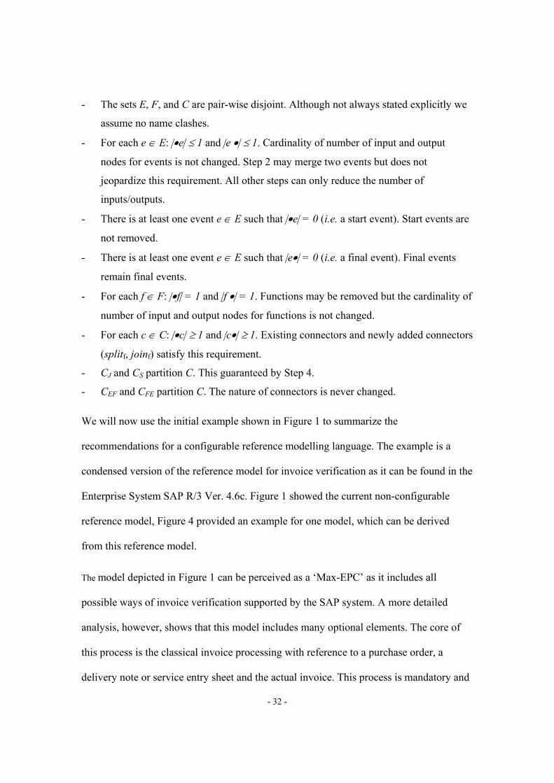
- The sets E, F, and C are pair-wise disjoint. Although not always stated explicitly we
assume no name clashes.
- For each e ∈ E: |•e| ≤ 1 and |e •| ≤ 1. Cardinality of number of input and output
nodes for events is not changed. Step 2 may merge two events but does not
jeopardize this requirement. All other steps can only reduce the number of
inputs/outputs.
- There is at least one event e ∈ E such that |•e| = 0 (i.e. a start event). Start events are
not removed.
- There is at least one event e ∈ E such that |e•| = 0 (i.e. a final event). Final events
remain final events.
- For each f ∈ F: |•f| = 1 and |f •| = 1. Functions may be removed but the cardinality of
number of input and output nodes for functions is not changed.
- For each c ∈ C: |•c| ≥ 1 and |c•| ≥ 1. Existing connectors and newly added connectors
(splitf, joinf) satisfy this requirement.
- CJ and CS partition C. This guaranteed by Step 4.
- CEF and CFE partition C. The nature of connectors is never changed.
We will now use the initial example shown in Figure 1 to summarize the
recommendations for a configurable reference modelling language. The example is a
condensed version of the reference model for invoice verification as it can be found in the
Enterprise System SAP R/3 Ver. 4.6c. Figure 1 showed the current non-configurable
reference model, Figure 4 provided an example for one model, which can be derived
from this reference model.
The model depicted in Figure 1 can be perceived as a ‘Max-EPC’ as it includes all
possible ways of invoice verification supported by the SAP system. A more detailed
analysis, however, shows that this model includes many optional elements. The core of
this process is the classical invoice processing with reference to a purchase order, a
delivery note or service entry sheet and the actual invoice. This process is mandatory and

- 33 -
all elements have to be configured. Evaluated receipt settlement (ERS) is an option that
allows bypassing the entire classical invoice verification process. Based on long term
contracts and a clear specification of the goods, invoices are posted and released based on
the arrival of goods which conform in quantity and quality to the specifications of the
purchase order or contract. Thus, ERS is typically only a relevant option, if the company
is of significant size and the business relationship is based on a highly repetitive
purchasing process based on a long-term contract with a clear specification of the
payment details. In a similar way, invoice plan settlement is an optional function. In this
case, invoices are consolidated in an invoice plan and scheduled over a series of future
dates independently of individual procurement transactions and the actual receipt of
goods and services. This is relevant for regularly recurring procurement transactions (e.g.
car leasing, subscriptions) (so called periodic invoicing plan) and transactions that are
subject to stage payments (e.g. a building project) (so called partial invoicing plan).
Invoicing plan settlement facilitates the automatic creation and payment of invoices and
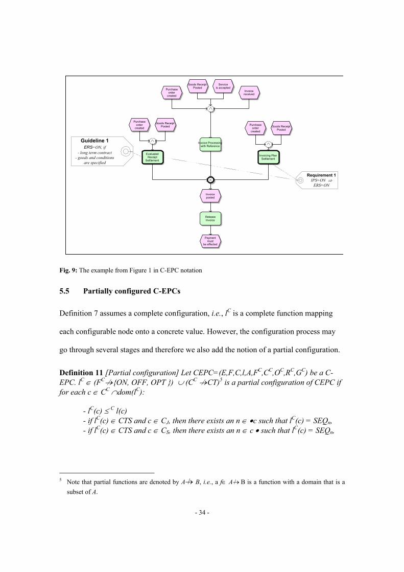
uses functionality of the evaluated receipt settlement solution [37]. Figure 9 shows the
reference model in C-EPC notation that can be derived from this description.
- 34 -
Fig. 9: The example from Figure 1 in C-EPC notation
5.5 Partially configured C-EPCs
Definition 7 assumes a complete configuration, i.e., lC is a complete function mapping
each configurable node onto a concrete value. However, the configuration process may
go through several stages and therefore we also add the notion of a partial configuration.
Definition 11 [Partial configuration] Let CEPC=(E,F,C,l,A,FC,CC,OC,RC,GC) be a C-EPC. lC ∈ (FC→/ {ON, OFF, OPT }) ∪ (CC →/ CT)5 is a partial configuration of CEPC if for each c ∈ CC ∩dom(lC):
- lC(c) ≤ C l(c) - if lC(c) ∈ CTS and c ∈ CJ, then there exists an n ∈ •c such that lC(c) = SEQn, - if lC(c) ∈ CTS and c ∈ CS, then there exists an n ∈ c • such that lC(c) = SEQn,
5 Note that partial functions are denoted by A→/ B, i.e., a f∈ A→/ B is a function with a domain that is a
subset of A.
Goods ReceiptPosted
Serviceis accepted
Invoicereceived
ReleaseInvoice
Invoice Processingwith Reference
Purchaseorder
created
EvaluatedReceipt
Settlement
Invoicing PlanSettlement
Paymentmust
be effected
Goods ReceiptPosted
Purchaseorder
created Goods ReceiptPosted
Purchaseorder
created
Invoiceposted
Guideline 1ERS=ON, if
- long term contract- goods and conditions
are specified
Requirement 1IPS=ON ⇒
ERS=ON
- 35 -
One can think of a C-EPC with a partial configuration as another C-EPC. Using an
algorithm similar to the one described in Definition 10, one can transform C-EPC with a
partial configuration into a new C-EPC. We omit details, but it is straightforward to
realize this using Definition 10. Simply consider the configurable nodes that are not
configured as unconfigurable nodes when applying the algorithm. Let β′ be the modified
algorithm which transforms a C-EPC with a partial configuration into a new C-EPC.
Without proof we give the following theorem.
Theorem 2 [β(CEPC,lC) is an EPC] Let CEPC1 be a C-EPC and lC a partial configuration of CEPC. CEPC2=β′(CEPC1,lC) is the corresponding C-EPC.
- If CEPC2 is satisfiable, then CEPC1 is also satisfiable. - If lC
2 is a valid (suitable) configuration of CEPC2, then lC2 is also a valid
(suitable) configuration of CEPC1
The above allows us to indicate whether a partial configuration of a C-EPC is satisfiable.
The concept of partial configured C-EPC opens up interesting possibilities. Consider for
example a configurable Enterprise System like SAP. There could be a top-level C-EPC
which indicates all possible configurations of SAP with respect to a given process. This
C-EPC could be partially configured per industry. (Recall that SAP has 27 alternative
industry solutions, as indicated in Section 3.) In other words, for each industry there are
partial configured C-EPCs. Such partial configured C-EPCs can be used as a starting
point within a given organization. For large organizations there may be different versions
of the same process, e.g., per country or per region. However, at the same time the
organization may want to enforce some unification. Therefore, the industry specific C-
EPC may be partially configured into an organization-specific C-EPC. The latter C-EPC
may be configured within specific parts of the organization (e.g., per region). This
- 36 -
example shows that it may be worthwhile to have (partially configured) C-EPCs at
different levels where at each level the lower level is a (partial) configuration of the upper
level. For example, there may be a C-EPC at the level of SAP (What can the system do?),
at the level of an industry (What configurations of SAP make sense for the automotive
industry?), and at the level of one organization (What configurations do we allow within
our organization?). Only the C-EPC at the organizational level is configured completely
to support a concrete process within some part of the organization (How do we do this
process within the Eindhoven branch of our organization?).
Apart from configuration at various levels there can always be the need for customization
(i.e., support processes that do not fit into the C-EPC). The latter should be avoided (if
possible) since it is risky and costly. If customization is unavoidable, it may be interesting
to use the notions of inheritance described in [2,5]. These notions of inheritance can
easily be applied to EPCs and C-EPCs. The topic of customization is however out of the
scope of this paper.
5.5 Extensions
To conclude this section we reflect on the requirements given in Section 4 in the context
of the C-EPC language just defined.
a) The C-EPC language defined in this section mainly focuses on the process and
control-flow aspects. The data aspect and function aspect have not been addressed
explicitly. Note that functions can be configured but this only refers to their
presence rather than the functionality of these functions.
b) C-EPCs do not distinguish between mandatory and optional decisions. However,
it is fairly easy to add this functionality. It could be defined as an extension of the

- 37 -
partial order OC. It is also possible to extend the language with defaults for
optional configuration decisions.
c) C-EPCs do not differentiate between global and local decisions. Again it is fairly
easy to add this as an attribute to all configurable nodes. However, the real
challenge is to get this information.
d) Similarly remarks hold for the difference between critical and non-critical
decisions.
e) Configuration decisions can have interrelationships. This is partly covered by the
requirements (RC) and guidelines (GC) in a C-EPC. However, these are restricted
to interrelationships within one model and not for e.g. interrelationships between
two process models and interrelationships between a reference process model and
a related reference data model.
f) Configuration decisions can be made on different levels. This can be supported by
the partially configurable C-EPCs as discussed in the previous subsection.
g) In a C-EPC variation points do not refer to further related information within the
Enterprise System. However, this can be added easily.
h) The entire configuration process should also be guided by recommendations or
configuration guidelines. This is supported by the guidelines (GC) and the partial
order OC.
i) The last requirement refers to the impact of configuration extensions on the
perceived model complexity. The C-EPC is a natural extension of the standard
EPC and should not cause any problems for the typical user of a reference model.
The most complex parts are the interrelationships defined in the requirements (RC)
- 38 -
and guidelines (GC) in a C-EPC since these are expressed in logical expressions. It
may be worthwhile to think of more graphical notations for modelling typical
requirements like for example dependency constraints.
As indicated the C-EPC language defined in this paper covers many of the requirements
but not all. The language reported in this paper focuses on the core functionality of a
configurable reference modelling language based on EPCs.
6 Related Work
This area of research can be divided into requirements engineering for the development of
Enterprise Systems [10,12] and requirements engineering for the configuration of
Enterprise Systems. The latter one is the focus of this paper. Academic contributions in
this field are still the exception.
Soffer et al.’s [41] suggestions on ERP modelling can be regarded as the closest to our
proposed ideas. The goal of their paper is to determine what language is most appropriate
for representing ERP system capabilities. Following the concept of scenario-based
requirements engineering, Soffer et al. evaluate the Object-Process Modelling
Methodology. The so-called argumentation facet, related to the ability of a modelling
language to express optionality-related information, is just one of many of their criteria.
The paper does not comprehensively analyse requirements related to modelling
Enterprise Systems configurability and evaluates an existing technique rather than
developing a new and more appropriate technique.

- 39 -
A number of papers have contributed to the area of goal modelling and the
interrelationships of goal models to other model types and requirement specifications. As
an example, Rolland and Prakesh [31] suggest a map including ERP goals and objectives
for the identification and evaluation of user needs. In [30], Rolland links goals and
strategies in so called maps. She applies this idea to processes from SAP’s Material
Management (MM) solution. This interesting work stays on the rather high level of goals
and strategies, does not utilise techniques and contents of existing reference models and
is very brief regarding configurability of goals and related processes.
Further work on goal modelling has been conducted by Soffer and Wand [42], who
propose a generic theory-based process modelling framework based on Bunge’s ontology
for a goal-driven analysis of process model validity. Giorgini et al. [19] present a formal
framework for reasoning with goal models. All these papers do not consider the
configurability of models and do not study modelling techniques which are widely
utilised in practice.
Gulla and Brasethvik [20] introduce three process modelling tiers to manage the
complexity of process modelling in comprehensive ERP Systems projects. Their
functional tier dimension deals with the functionality of the Enterprise System. However,
they do not study how reference models fit into in this tier. Brehm et al. [9] discuss
alternative ways of configuring Enterprise Systems. Their taxonomy for ERP
configuration and customising is widely cited. However, they do not demonstrate how
this work can be linked to reference models of Enterprise Systems.

- 40 -
Related work has also been conducted in the area of variability management in software
families. Halmans and Pohl [21] discuss issues related to the communication of the
variability of a software-product family. They propose an extension to use case diagrams
based on cardinalities in order to explicitly depict variation points. They do not support
dependencies between variation points. Moreover, use case diagrams have not widely
been used for reference models. Halmans and Pohl [21] have been influenced by previous
work on representing variability in use case diagrams by Bertolino et al. [8], von der
Massen and Lichter [27], and John and Mutig [22]. Software product families have also
been investigated in from an architectural viewpoint. In fact, there have been several
workshops on software architectures for product families, cf. [26]. As an example
consider the work of Dolan et al. [15] on the role of the various stakeholders when it
comes to software product families. All these publications do not relate to large
Enterprise Systems solutions and process modelling techniques which are used in this
context.
7 Conclusion and Outlook
Reference models have been defined in this paper as reusable conceptual models that
depict recommended structures and processes. One main class of reference models are
application reference models that document the functionality of off-the-shelf-solutions.
Reference modelling languages face specific requirements regarding the configuration of
these models. However, current models such as the SAP reference models (and other
Enterprise Systems reference models) are designed using modelling languages that do not
cater for the needs of configuration. Thus, only limited opportunities exist to specify valid
configurations. This paper proposed a new dedicated reference modelling language that
- 41 -
allows exactly this explicit specification of configurations in reference process models.
This language has been called Configurable EPCs and has been derived from the popular
EPCs.
The current focus of our research is on developing a list of configuration patterns and
exploring alternative ways of modelling these patterns. The quality of our proposed
reference modelling language as well as its notations will be tested in experiments and
focus groups. This project is funded by SAP Corporate Research and it is the explicit aim
to develop an applicable language. As part of this research project, a related SAP-funded
empirical study on the actual modelling practice in Australia is currently conducted. This
study will give important insights into the problems with the existing reference models.
Furthermore, it is planned to extend this work to configurable collaborative business
scenario diagrams.
Another interesting question is: "Given a C-EPC and a partial configuration, is the partial
configuration satisfiable?". Related questions are: "If not satisfiable, why not?" or "If
satisfiable, which configurations are still possible?". Since the number of configurations
is finite, it is easy to provide automated support for addressing these questions. Moreover,
it would be interesting to link these questions to the dynamics of the resulting EPCs. It
may be the case that a partial configuration satisfiable in terms of the configuration
requirements but that the resulting EPCs will always deadlock.
A further area of research will be the inclusion of evidence-based research. This could
include access to relevant benchmarking information or typical configuration decisions
made in one industry sector. This could be visualised in the reference models using the
proposed configuration guidelines and would provide valuable guidance for the required

- 42 -
decisions. Clearly this is also linked to the topic of process mining (cf.
www.processmining.org), i.e., extracting knowledge from event logs. By analysing the
logs of SAP and other Enterprise Systems one can link certain performance metrics to
configuration decisions.
8 References
[1] W.M.P. van der Aalst, Formalization and Verification of Event-Driven Process Chains, Information and Software Technology 41(10) (1999) 639-650. [2] W.M.P. van der Aalst, T. Basten, Inheritance of Workflows: An Approach to Tackling Problems Related to Change, Theoretical Computer Science, 270(1-2) (2002) 125-203. [3] W.M.P. van der Aalst, J. Desel, E. Kindler, On the Semantics of EPCs: A Vicious Circle. In M. Nüttgens and F.J. Rump, editors, Proceedings of the EPK 2002: Business Process Management using EPCs, Trier, Germany, November 2002. Gesellschaft für Informatik, Bonn, 71-80. [4] W.M.P. van der Aalst, A.H.M. ter Hofstede, B. Kiepuszewski, A.P. Barros, Workflow Patterns, Distributed and Parallel Databases 14(3) (2003) 5-51. [5] T. Basten, W.M.P. van der Aalst, Inheritance of Behavior. Journal of Logic and Algebraic Programming, 47(2) (2001) 47-145. [6] J. Becker, M. Kugeler, M. Rosemann, eds., Process Management, Berlin et al., 2003. [7] P. Bernus, GERAM: Generalised Enterprise Reference Architecture and Methodology, version 1.6.3, March 1999. [8] A. Bertolino, A. Mantechi, S. Gnesi, G. Lamir, A. Maccari, Use Case Description of Requirements for Product Lines. Proceedings of the International Workshop on Requirements Engineering for Product Lines 2002 - REPL ’02. Technical Report: ALR-2002-033, AVAYA labs. 2002. [9] L. Brehm, A. Heinzl, M.L. Markus, 2000, Tailoring ERP Systems: A Spectrum of Choices and their Implications, Proceedings of the 34th Hawaii International Conference on System Sciences. Maui, Hawaii, 3-6 January 2000. [10] S. Brinkkemper, Requirements Engineering for ERP: Requirements Management for the Development of Packaged Software, Proceedings of the 4th International Symposium on Requirements Engineering. Limerick, Ireland, 7-11 June 1999. [11] T. Curran, G. Keller, SAP R/3 Business Blueprint: Understanding the Business Process Reference Model, Upper Saddle River, 1997. [12] M. Daneva, Practical Reuse Measurement in ERP Requirements Engineering, Proceedings of the 12th International Conference CAiSE 2000, eds., B. Wangler and L. Bergman. Stockholm, Sweden, June 5-9, Lecture Notes in Computer Science 1789, 2000, 309-324.

- 43 -
[14] J. Dehnert, P. Rittgen, Relaxed Soundness of Business Processes, In K.R. Dittrich, A. Geppert, and M.C. Norrie, editors, Proceedings of the 13th International Conference on Advanced Information Systems Engineering (CAiSE 2001), volume 2068 of Lecture Notes in Computer Science, Springer-Verlag, Berlin, 2001, 157-170. [15] T. Dolan, R. Weterings, J.C. Wortmann, Stakeholder-Centric Assessment of Product Family Architecture: Practical Guidelines for Information System Interoperability and Extensibility, In International Workshop on Software Architectures for Product Families (IW-SAPF-3), volume 1951 of Lecture Notes in Computer Science, Springer Verlag, 2000, 225-245. [16] P. Fettke, P. Loos, Classification of reference models - a methodology and its application. Information Systems and e-Business Management, 2003, 1(1) 35-53. [17] T. Forsberg, G. Roenne, J. Vikstroem, Process Modeling in ERP Projects – a discussion of potential benefits. Intentia R&D 2002. [18] U. Frank, Conceptual Modelling as the Core of the Information Systems Discipline - Perspectives and Epistemological Challenges, Proceedings of the America Conference on Information Systems – AMCIS ’99, Milwaukee, 1999, 695-698. [19] P. Giorgini, J. Mylopoulos, E. Nicchiarelli, R. Sabastiani: Formal Reasoning Techniques for Goal Models. Journal on Data Semantics, 2004, 1(1), 1-20. [20] J. A. Gulla, T. Brasethvik, On the Challenges of Business Modeling in Large Scale Reengineering Projects,. Proceedings of the 4th International Conference on Requirements Engineering, Schaumburg, Ill., 19-23 June 2000, 17-26. [21] G. Halmans, K. Pohl, Communicating the variability of a software-product family to customers. Software and Systems Modeling, 2(1) 2003 15-36. [22] I. John, D. Mutig, Tailoring Use Cases for Product Line Modeling. Proceedings of the International Workshop on Requirements Engineering for Product Lines 2002 - REPL ’02. Technical Report: ALR-2002-033, AVAYA labs 2002. [23] G. Keller, M. Nüttgens, A.W. Scheer, Semantische Processmodellierung auf der Grundlage Ereignisgesteuerter Prozessketten (EPK), Veröffentlichungen des Instituts für Wirtschaftsinformatik, Heft 89 (in German), University of Saarland, Saarbrücken, 1992. [24] H. Klaus, M. Rosemann, G.G. Gable, What is ERP?, Information System Frontiers (2000) 2 (2) 141-162. [25] P. Langner, C. Schneider, J. Wehler, Petri Net Based Certification of Event driven Process Chains. In J. Desel and M. Silva, editors, Application and Theory of Petri Nets 1998, volume 1420 of Lecture Notes in Computer Science, Springer-Verlag, Berlin, 1998, 286-305. [26] F. van der Linden, eds., International Workshop on Software Architectures for Product Families, volume 1951 of Lecture Notes in Computer Science, Berlin 2000. [27] T. von der Massen, H. Lichter, Modeling Variability by UML Use Case Diagrams. Proceedings of the International Workshop on Requirements Engineering for Product Lines 2002 - REPL ’02. Technical Report: ALR-2002-033, AVAYA labs. 2002. [28] V.B. Misic, J.L. Zhao, Evaluating the Quality of Reference Models, in A.H.F. Laender, S.W. Liddle, V.C.Storey, eds., in Proceedings of the 19th International

- 44 -
Conference on Conceptual Modeling. Salt Lake CIt, Utah, USA, 9-12 October 2000. Lecture Notes in Computer Science 1920, 484-498. [29] P. Rittgen, Modified EPCs and their Formal Semantics. Technical Report 99/19, University of Koblenz-Landau, Koblenz, Germany, 1999. [30] C. Rolland: Aligning Business and System Functionality Models. Proceedings of the 3rd Pre-ICIS Workshop on Process Management and Information Systems. Eds.: J. Akoka, I. Comyn-Wattiau and M. Favier. Washington D.C., 12 December 2004, 1-10. [31] C. Rolland, N. Prakash, Bridging the Gap between Organisational Needs and ERP Functionality, Requirements Engineering, 5 (3) (2000) 180-193. [32] M. Rosemann, ERP software: characteristics and consequences, in J. Pries-Heje et al., eds., in Proceedings of the 7th European Conference on Information Systems, 23-25 June 1999, Copenhagen. [33] M. Rosemann, Using Reference Models within the Enterprise Resource Planning Lifecycle. Australian Accounting Review, 10(3) 2000 19-30. [34] M. Rosemann, Application Reference Models and Building Blocks for Management and Control (ERP Systems). in: Handbook on Enterprise Architecture. P. Bernus, L. Nemes, G. Schmidt, eds., Springer-Verlag: Berlin et al., 2003, 595-616. [35] M. Rosemann, G. Shanks, Extension and Configuration of Reference Models for Enterprise Resource Planning Systems. Proceedings of the 12th Australasian Conference on Information Systems - ACIS 2001, G. Finnie, D. Cecez-Kecmanovic, B. Lo, eds., Coffs Harbour, 4-7 December 2001, 537-546. [36] F. Rump, Geschäftsprozessmanagement auf der Basis Ereignisgesteuerter Prozessketten. Reihe Wirtschaftsinformatik, Teubner Verlag, Germany, 1999. [37] Online Documentation mySAP ERP, SAP AG, (help.sap.com)., 2005. [38] A.-W. Scheer, ARIS – Business Process Modelling. 3rd ed., Berlin et al., 2000. [39] L. Silverston, The Data Model Resource Book, Volume 1, A Library of Universal Data Models for All Enterprises, revised edition, 2001. [40] L. Silverston, The Data Model Resource Book, Volume 2, A Library of Data Models for Specific Industries, revised edition, 2001. [41] P. Soffer, B. Golany, D. Dori: ERP modelling – a comprehensive approach. Information Systems, 28 (2003), 673-690. [42] P. Soffer, Y. Wand: Goal-Driven Analysis of Process Model Validity. In: Advanced Information Systems Engineering. Proceedings of the 16th International Conference (CAiSE 2004). Eds.: A. Persson, J. Stirna. Riga, Latvia, June 2004, 521-535. [43] M. Verbeek, On Tools & Models, in: Dynamic Enterprise Innovation. Establishing Continuous Improvement in Business. 3rd ed., R. van Es, ed., 1998.


![MPC8548E Configurable Development System … Configurable Development System Reference Manual, ... [4:0] ... MPC8548E Configurable Development System Reference Manual,](https://img.pdfslide.us/doc/110x75/5af028337f8b9ac62b8e4c0e/mpc8548e-configurable-development-system-configurable-development-system-reference.jpg)