Embed Size (px)
Citation preview
R 710 Philips Res. Repts 24, 559-571,1969
A COMPUTATION OF THE HIGH-FREQUENCY NOISEQUANTITIES OF A MOS-FET
by F. M. KLAASSEN *)
AbstractBy adding a thermal-noise source to the transport equations the fourhigh-frequency noise quantities of the MOS-FET have been computedas a series of the normalized angular frequency. In addition the substratedepletion charge has been taken into account. Numerical results aregiven for the dependency of the noise quantities on the substrate doping.With these results it is possible to express the minimum noise factorin simple terms of the frequency and the gain-bandwidth product.Moreover the results support the validity of approximate simple expres-sions obtained by means of the equivalent circuit.
1. Introduetion
By introducing thermal-noise sources to all resistive parts of the equivalentcircuit the high-frequency noise quantities of a MOS-FET may be convenientlycomputed 1.2). For the minimum noise factor (Fmin) a very practical expres-sion has been obtained in this way 2). However, this expression is only a goodapproximation because one has to use a rather unknown value for the corre-lation factor between gate and drain noise current. Nevertheless, comparisonof the theoretical results with experimental values has led to reasonable agree-ment.
A more complicated but more accurate way of computing the noise of thedevice makes use of the transport equations, to which a thermal-noise sourcehas to be added. For that purpose the channel is split into small infinitesimalparts and it is assumed that all these parts act as independent noise sources.Computations on these lines have been published both for the junction-gateFET and for the MOS-FET 3-6). Unfortunately, none of these papers givesan expression for the minimum noise factor, which is valid for frequenciesnear the limit of operation. To a great extent this is due to the fact that mostauthors have neglected the real part ofthe correlation factor between the equiv-alent noise voltage and the equivalent noise current. It is the aim of this paperto obtain values for Fm1n which are also valid for frequencies beyond the cut-offfrequency of the device. Moreover, the results support the validity of theapproximate simple expressions 2) obtained by means of the equivalent circuit.
*) Temporarily at Northern Electric Research and Development Laboratories, Ottawa,Canada.
dl d= WCox-/(Vg, V),
dt
(1)
560 F. M. KLAASSEN
Generally the method used is the following. With the aid of the modifiedtransport equations an equivalent input noise voltage and noise current havebeen computed, which make the noise output of the device zero. Due to thecomplexity of the equations these quantities have been obtained as a series ofthe angular frequency co.Finally, with the equivalent input quantities, the noiseresistance, the noise conductance, the correlation factor and the minimumnoise factor have been computed.
2. The basic equations
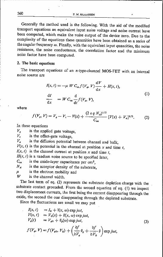
The transport equations of an n-type-channel MOS-FET with an internalnoise source are
dVlex, t) = -p, WCoJ (Vg, V) - + H(x, t),
dx
dxwhere
(2 e N )1/2I(Vg, V) = Vg - Vt - Vex) + q A [Vex) + VaF/2. (2)
CoxIn these equationsVg is the applied gate voltage,Vt is the offset-gate voltage,Va is the diffusion potential between channel and bulk,Vex, t) is the potential in the channel at position x and time t,lex, t) is the channel current at position x and time t,H(x, t) is a random noise source to be specified later,Cox is the oxide-layer capacitance per cm",NA is the acceptor density of the substrate,p, is the electron mobility andW is the channel width.The last term of eq. (2) represents the substrate depletion charge with the
substrate contact grounded. From the second equation of eq. (1) we inspecttwo displacement currents, the first being the current disappearing through theoxide, the second the one disappearing through the depleted substrate.Since the fluctuations are small we may put
= 10 + i(x, co)exp jon,= Vo(x) + vex, co)exp jon,= VgO+ vg(co) expjcot,
( "fJI "fJ/)I (Vg, V) =I (Voo, Vo) + - Vg+-- V exp joit,"fJVg "fJVo
lex, t)vex, t)Vg(t) (3)
di ( dj )- = j (1) W Cox -- V + Vg .dx dVo
Applying a sufficiently large a.c. gate voltage Vg under the condition that thedrain is short-circuited for a.c. voltages (Vd = 0) the noise source H(x) maybe neglected in eq. (5) and the value of the transconductance is obtained.Integrating eq. (5) over x = 0 --)0- I we easily compute for the low-frequency
(6)
HIGH-FREQUENCY NOISE QUANTITIES OF A MOS-FET-------
561
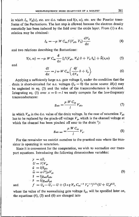
in which 10, Vo(x), etc. are d.c. values and i(x, (1)), etc. are the Fourier trans-forms of the fluctuations. The last step is allowed because the electron densityessentially has been induced by the field over the oxide layer. From (1) a d.c.relation may be obtained:
(4)
and two relations describing the fluctuations:d _
i(x, (1)) = -p, W Cox - [f(Voo, Vo) V + Vo Vg] + h(x,(1)) (5)dx
and
transcond uctance:
(7)
in which VdO is the d.c. value of the drain voltage. In the case of saturation VdO
has to be replaced by the pinch-off voltage Vp, which is the channel voltage atwhich the channel has been pinched off near to the drain 7):
p,WCOK
gmO sat = Vp•I
(8)
For the remainder we restrict ourselves to the practical case where the tran-sistor is operating in saturation.Since it is convenient for the computation, we wish to normalize our trans-
port equations. Introducing the following dimensionless variables:
y = x/I,u= V/Vp,
il = iJfvgo,W = (1) f2/p,Vp,
s = i/grnovgo,r = ii/gmovgo
and f =Uo-Ut-U+(2eqNACox-2Vp-l)1/2(U+Ua)1/2,
where the value of the normalizing gate voltage VOO will be specified later on,the equations (4), (5) and (6) are changed into
(9)
562 F. M. KLAASSEN
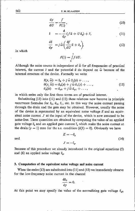
dy fdU -;- F(l) ,
(10)
d=-- (fti + UUg) + r,
dy
• A (df _ + _)dy =JW dUll Ug,
(11)
ds(12)
in whichI
F(I) = JfdU.o
Although the noise source is independent of m for all frequencies of practicalinterest, the current s and the potential u do depend on m because of theinternal structure of the device. Formally we write
s(y, m) = So + j W SI(Y) + ... ,fi(y, m) = uo(y) + j m fil(y) + ... ,fig(m) = figo + j m tigl + ... ,
(13)
in which series only the first three terms are of practical interest.Substituting (13) into (11) and (12) these relations now become in principle
recurrence formulae for So, fio, S1> etc. In this way the noise current passingthrough the drain and the gate may be obtained. However, usually the noiseof the device is represented by an equivalent noise voltage E and an equiv-alent noise current J at the input of the device, which is now assumed to benoise-free. These quantities are obtained by computing the value of an appliedgate voltage Vg and an applied gate current Ig which make the noise current atthe drain (y = 1) zero for the S.C. condition (u(l) = 0). Obviously we have
and (14)J = -ig.
Because of this procedure we already introduced in the original equations (5)and (6) an applied noise voltage Vg.
3. Computation of the equivalent noise voltage and noise current
When the series (13) are substituted into (11) and (12) we immediately observefor the low-frequency noise current in the channel
dso-=0.dy
At this point we may specify the value of the normalizing gate voltage Voo
HIGH-FREQUENCY NOISE QUANTITIES OF A MOS-FET 563
already introduced in (9). We chose VgO such that the low-frequency noisecurrent at the drain becomes zero:
SdO = so(l) = O.
Integrating eq. (11) over y = 0 ---+ 1 we obtain1
UgO =Jrdy.o
(15)
Moreover, integrating over y = 0 ---+ y' the expression for the low-frequencyfluctuating channel potential uo(y) is given by
(16)
This last relation can be used to compute the next term of the series (13).Using again the conditions Sl(1) = 0 we obtain from (12)
(17)
Since we have from (11)1
Ug1 =- J SI dyo
we finally obtain for the induced gate voltage
(18)
Of course, the applied voltage Ug1 alone cannot make the device to be noise-free.We also have to apply an extra gate current Sgl such that
(19)
in which s(O) is the channel noise current at the source.Since we also want to know higher-order terms, we need an expression for
the fluctuating channel potential ul(y). This quantity may be obtained by inte-grating (11) over y = 0 ---+ y'. The result is given by
U 1 y
ul(Y) = -7U9l - j / Sl(Y) dy. (20)
564 F. M. KLAASSEN
Finally by analogy to the formulae (18) and (19) the expressions for the second-order terms ug2 and Sg2 read
1 dfUg2 = J (dUU1 +Uo1)YdY
o(21)
and
(22)
Although higher-order terms may be easily derived, we will not give themhere, because it can be shown that their contribution to the noise characteristicscan be neglected for frequencies of practical interest. At frequencies three timesthe gain-bandwidth product (a, = 3) this contribution is only a few per cent.With formulae (14), (15), (18), (19), (21) and (22) the equivalent noise volt-
age E and the equivalent noise current J are known in principle.Usually four quantities are used to characterize the noise of a device:
the noise resistance<EE*)
R=--n 4kT'
<JJ*)G=--r 4kT'
<EJ*)CP=~+j",=--,
2kT(25)
(23)
the noise conductance (24)
and the correlation
in which E*, etc. are the complex conjugates and the correlation factor is acomplex number. Except for low frequencies also the minimum noise factor isan important practical quantity:
Fm1n =~+ (4 R; G, - ",2)1/2 + 1. (26)
In order to elaborate these defined expressions we need to specify the internalnoise source. Restricting ourselves to high frequencies and to room temperatureor higher, so that no other noise sources are important B), our noise source isof thermal origin and given by Nyquist's formula as modified by (9):
4 k T fl W Cox Vpf c5(x- x')<feY) f(y')*) = (p, C W /-1 V)2 - 2
ox p VoOor
. 4 k Tfc5(y ') .<feY) r(y')*) = - Y ,
- 2glllo VOO(27)
where the delta function represents the mutual independenee of the noisesources. Using (27) together with (14), (15), (18), (19), (21) and (22) the expres-
HIGH-FREQUENCY NOISE QUANTITIES OF A MOS-FET
sions for the noise quantities (23) to (26) can be further elaborated. In this caseit is convenient, after 'taking into account the effect of the delta function, tochange variables by means of formula (10). When the integration of (10) hasbeen carried out we have
u
l/dU F(U)y = -1 _.- = F(I) .
JldUo
The result of all elaborations will be given in the next section.
4. A procedure for the computation of the noise quantities
When the expressions (23) to (26) have been elaborated with the aid of (10),(14), (15), (18), (19), (21), (22), (27) and (28), the noise quantities may be com-puted with the following program:
Rno gmO
Grgmo-1
Rn1 s.«g
_ ~ 2- VgO ,
= W2 ig12,= W2 (Vg12 - 2 VooV02),= 2 w2 (Vgl iOl - voo ï02),= -2 W (vooio1),= ~+ (4 Rn G, - ,,2)1/2 + 1,
in which the voltages voo, etc. are given by
1
Vo02 = [F(1)]-1 J j2 dU,o111
voo VOl = [F(1)]-3 J j2 dU J g F dU' - Vo02 tF(I)]-Z J (U g - I) F dU,o u o1 1
VgOZ9l = [F(1)]-2 JI2dU JgdU'-vgo2 [F(1)]-1 J(Ug-/)dU,o u o1 1
Vg/ = [F(l)]-S J I? dU [f g FdU']2 + Vg02 [F(I)]-4 [f (U g- I) FdU]2 +
o u o1 1
-2 [F(l)]-s Jj2 «u JgFdU' J(Ug-f) FdU,o u 0
1 1 1
ï012 = [F(I)]-3 J j2 dU [f g dUF + Vo02 [F(l)]-Z [f (U g- f) dU]2 +o U 0
1 1
-2 [F(1)]-3 J j2 dU J g dU' J (U g- f) dU,o u 0
565
(28)
566 F. M. KLAASSEN
1 1 1
VOl iOl = [F(1)]-4 lP dU I g F dU' I g dU" + ;o U U
1 1 1
-[F(1)]-4 IPdU IgdU' I(Ug-f)FdU+o U 0
1 1 1
-[F(1)]-4 lP dU I gFdU' I(U g-f) dU +o U 0
1 1
+ voo2 [F(1)]-3 I (U g -f) dU I (U g - f) F dU,o 0
1 1 U' 1 1 1
VOO V02= [F(l)]-S {fP dU I g dU' I gF2 dU" +lP dU I gF dU' I gFdU" +o U 0 0 U u'
1 1 . 1
- lP dU I g FdU' I g U FdU} +o U 0
1 1 1 1
+ voo2 [F(1)]-4 {f gU FdU I (Ug-f)FdU- IgF2dU l(gU'-f)dU+o 0 0 U
1 U'
- I g F dU I (g U' -f) F dU'} + 1- VOO VOl>o 0
1 1 U' 1 1 1
VOO i02 = [F(1)]-4 {fP dU I g dU' I gFdU" + I f2 dU I gFdU' I g dU" +o U 0 0 U U'
1 1
- lP dUI gF dU 1Ug dU} +o U 0
1 1
+ vo02 [F(1)]-3 {fg UdU I(Ug-f)FdU +o 0
1 1 U
- IgFdU lss U'-f)dU- IgdU I(g U'-f)FdU'} + VOO Vgl.o U 0 0
In these equations the following basic functions are used: the pinch-off voltageis given by 7)
a2 aV = V +- - - (a2 + 4 V + 4 V )1/2•
PO 2 2 9.D
where(2 esl q NA)1/2
a=
HIGH-FREQUENCY NOISE QUANTITIES OF A MOS-FET 567
V a ( V)1/2jCU)=_!!_-U--- U+~ ,Vp Vp
1/2 Vp
V Ct [( V)3/2 (V)3/2JFCU)= ~ U- t U2 - t --1-/2 U+ ~ - ~ .~ ~ ~ ~
a ( V)-1/2gCU)=-I--- U+~ .
2 V//2 Vp
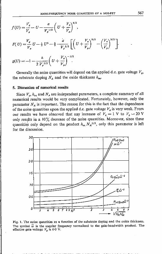
Generally the noise quantities will depend on the applied d.c. gate voltage Vg,the substrate doping NA and the oxide thickness hox-
5. Discussion of numerical results
Since Vg, hOK and NA are independent parameters, a complete summary of allnumerical results would be very complicated. Fortunately, however, only theparameter NA is important. The reason for this is the fact that the dependenceof the noise quantities upon the applied d.c. gate voltage Vg is very weak. Fromour results we have observed that any increase of Vg = 1 V to Vg = 20 Vonly results in a 10% decrease of the noise quantities. Moreover, since thesequantities only depend on the product hox NA1/2, only this parameter is 'leftfor the discussion.
Ok;;3£;;;4~~5~6~7~8~9jm~4==~~~2~~=t3===4~-5~~6~7- VNAhgx'
RnlgmoW-2
Fig. 1. The noise quantities as a function of the substrate doping and the oxide thickness.The symbol ~ is the angular frequency normalized to the gain-bandwidth product. Theeffective gate voltage Vg is 6,0 V.
568 F. M. KLAASSEN
In fig. 1 we plotted the numerical results obtained from the program men-tioned above with the normalized frequency w as a parameter. From the defini-tion of w it can be seen that the normalizing frequency is in fact the well-known gain-bandwidth product of the transistor. Practically only the fre-quencies w :::;;;3·0 are interesting, since for higher frequencies the power gainof the device will be too low.
From the plot we observe a steady increase of all quantities to be consideredwith the substrate doping and also by analogy with the oxide thickness. For thelow-frequency noise resistance Rno this behaviour already has been observedearlier 9). The main reason for this increase is the fact that devices with a highsubstrate doping, but with a transconductance and consequently a pinch-offvoltage equal to those of transistors with a low substrate doping, need a muchhigher applied gate voltage 7). This larger gate voltage then results in an increaseof the f function, in particular near the source (U = 0) and consequently inan increase of all integrals of the program.
From the figure one may conclude that the increase with frequency of thenoise resistance is not important for the practical frequency range. Althoughfor the lower frequencies also the real part of the correlation factor is small andmay be neglected compared with the other quantities, this is no longer the casefor higher frequencies (w ~ 1). In fact for w = 1, ~ contributes as much tothe value of the minimum noise factor as the other three quantities, becausetheir difference is of the same order of magnitude.
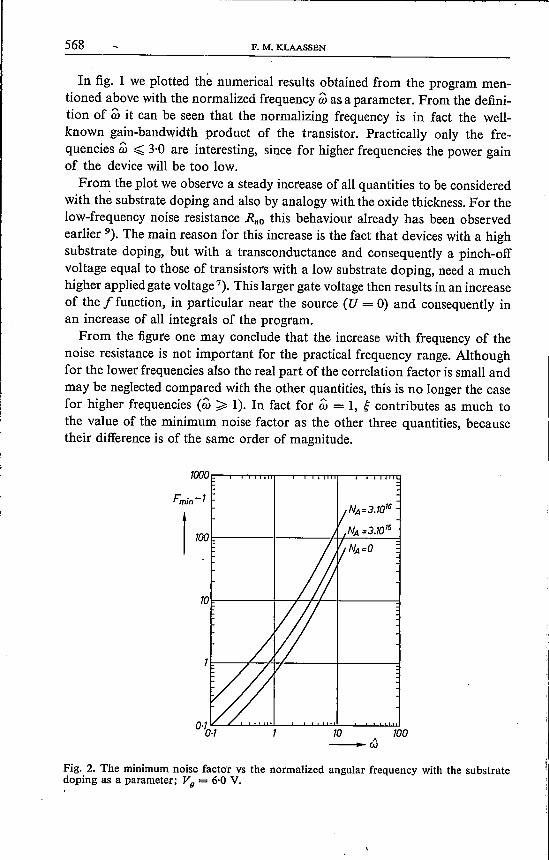
"-w
Fig. 2. The minimum noise factor vs the normalized angular frequency with the substratedoping as a parameter; Vg = 6·0 V.
HIGH-FREQUENCY NOISE QUANTITIES OF A MOS-FET
Since the limits of the noise quantities for NA = 0 could not be indicatedin the figure, we give these limits here. For NA ~ 0
Rno gmO ->-
o, gmo-1 W-2-+~ W-2 -+
0,667,0,267,0'151,
-+-0'667,-+ 0·0353.
Using the numerical values of fig. 1 we plotted in fig. 2 the value of theminimum noise factor as a function of the normalized angular frequency wwith the substrate doping as a parameter. In this plot we also observe for allfrequencies a steady increase of Frn1n with the substrate doping. For w < 1,(Frn1n - 1) increases linearly with the frequency, whereas for w» 1, (Frn1n - 1)increases with &2. Such a behaviour has been observed already from measure-ments of the noise factor of high-frequency MOS transistors 2).Finally, introducing the parameter IX = Rno gmO it is possible to represent
the numerical results with some simple formulae:
Rn ~ Rno (1+ 0·050 w2),
Gr ~ 0·40 IXglllo &2,
~ ~ 0·22 IX w2,A
U ~~IXW,
Frn1n ~ 1 + 0·80 IX w + 0·22 IX &2.
These formulae agree rather well with the results which have been obtainedby making use of the equivalent circuit of the transistor 2). From this agree-ment we may conclude that the complicated calculations presented here sup-port the validity of the simple calculation by means of the equivalent circuit.
Acknowledgement
The author is indebted to Mr D. Dijkstra for carefully programming theintegrals.
Ottawa, July 1969
List of symbols
(2 esl q NA)1/2jCox
oxide-layer capacitance per unit areaequivalent input noise voltageminimum noise factorfunction, representing the carrier density in the channelindefinite integral of f(V)
Frn1n
f(V)F(V)
569
.----------------------~-_._.~---- -
570 F. M. KLAASSEN
g(V)g",o
Gr
hoxH(x, t)'leX, w)lex, t)i(x, w)t,Jk1NAqRnRnorstTUi1Vex, t)VaVdVgVp
Vt
Wxy
wA
W
derivative of I(V)low-frequency transconductanceequivalent noise conductanceoxide thicknessrandom noise sourceFourier transform of H(x, t)channel currentFourier transform of lex, t)applied input noise currentequivalent input noise currentBoltzmann's constantchannel lengthacceptor density of the substrateelectron chargenoise resistancelow-frequency noise resistancenormalized noise source iïnormalized noise current in the channeltimetemperaturenormalized channel potentialnormalized Fourier transform of noise voltage ijchannel potentialdiffusion potential between channel and bulkd.c. value of applied drain voltaged.c. value of applied gate voltagepinch-off voltageoff-set gate voltagechannel widthposition in channelnormalized position in channeldielectric constant of the oxidedielectric constant of siliconreal part of correlation factorimaginary part of correlation factormobility of electronsnoise correlation factorangular frequencynormalized angular frequency
-\
HIGH-FREQUENCY NOISE QUANTITIES OF A MOS-FET 571
REFERENCES1) A. Leupp and M. J. O. Strutt, Electronics Letters 4, 313, 1968.2) F. M. Klaassen and J. Prins, IEEE Trans. EI. Dev. 16, November, 1969.3) A. van der Ziel, Proc. IEEE 51, 461-467, 1963.4) F. M. Klaassen, IEEE Trans. EI. Dev. 14, 368-373, 1967.5) P. S. Rao, Solid St. Electr. 12, 549-556, 1969.6) R. Paul, Nachrichten Technik 12, 458-466, 1967.7) J. A. van Nielen and O. W. Memelink, Philips Res. Repts 22, 55-7!, 1967.8) A. van der Ziel and K. Tagaki, Solid St. Electr., to be published.9) F. M. Klaassen and J. Prins, Philips Res. Repts 22, 505-514, 1967.