Embed Size (px)
Citation preview
CHEMICAL ENGINEERING DEPT.
FLUID FLOW UNIVERSITY OF AL-
MUTHANNA
Fluid Mechanics: Fundamentals and Applications,
2nd EditionYunus A. Cengel, John M.
CimbalaMcGraw-Hill, 2010
Lecture slides by
T.A Hayder K. Sakran
T.A Hayder Sakran
Chemical Engineering Dept. Fluid Flow University of AL-Muthanna 2013/2014
1
Chapter 1
INTRODUCTION AND BASIC CONCEPTS
Objectives
1. Understand the basic concepts of Fluid Mechanics.
2. Application Areas of Fluid Mechanics.
3. The No-Slip Condition.
4. Classification of Fluid Flows.
Viscous versus Inviscid Regions of Flow
Internal versus External Flow
Compressible versus Incompressible Flow
Laminar versus Turbulent Flow
Natural (or Unforced) versus Forced Flow
Steady versus Unsteady Flow
One-, Two-, and Three-Dimensional Flows
5. System and Control Volume.
6. Importance of Dimensions and Units.
7. Dimensional homogeneity.
T.A Hayder Sakran
Chemical Engineering Dept. Fluid Flow University of AL-Muthanna 2013/2014
2
1. INTRODUCTION:
Mechanics: The oldest physical science that deals with both stationary and moving bodies
under the influence of forces.
Statics: The branch of mechanics that deals with bodies at rest.
Dynamics: The branch that deals with bodies in motion.
Fluid mechanics: The science that deals with the behavior of fluids at rest (fluid statics) or
in motion (fluid dynamics) and the interaction of fluids with solids or other fluids at the
boundaries.
Fluid dynamics: Fluid mechanics is also referred to as fluid dynamics by considering fluids
at rest as a special case of motion with zero velocity.
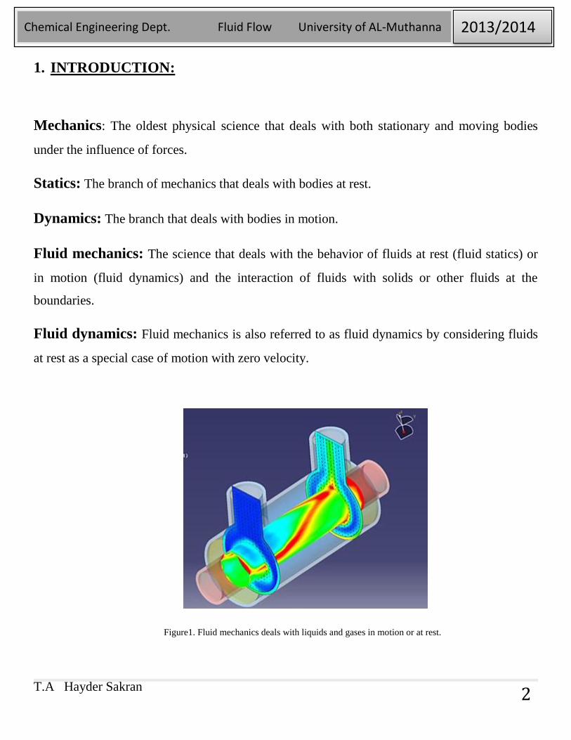
Figure1. Fluid mechanics deals with liquids and gases in motion or at rest.
T.A Hayder Sakran
Chemical Engineering Dept. Fluid Flow University of AL-Muthanna 2013/2014
3
Hydrodynamics: The study of the motion of fluids that can be approximated as
incompressible (such as liquids, especially water, and gases at low speeds).
Hydraulics: A subcategory of hydrodynamics, which deals with liquid flows in pipes and
open channels.
Gas dynamics: Deals with the flow of fluids that undergo significant density changes, such
as the flow of gases through nozzles at high speeds.
Aerodynamics: Deals with the flow of gases (especially air) over bodies such as aircraft,
rockets, and automobiles at high or low speeds.
Meteorology, oceanography, and hydrology: Deal with naturally occurring flows.
2. Application Areas of Fluid Mechanics:
Fluid Mechanics is increasingly performed in many engineering applications that can be applied
in:
1- Airplanes (aerospace engineering)
2- Motor vehicles (automotive engineering)
3- Breathing and blood flow(biomedical engineering)
4- Fluid flow through pumps and pipes(chemical engineering)
5- Rivers and pollutants (civil and environmental engineering)
6- Turbines and furnaces (power engineering)
7- Swimming and golf (sport engineering)
T.A Hayder Sakran
Chemical Engineering Dept. Fluid Flow University of AL-Muthanna 2013/2014
4
What Is a Fluid?
Fluid: A substance in the liquid or gas phase. A solid can resist an applied shear stress
by deforming. A fluid deforms continuously under the influence of a shear stress, no
matter how small. In solids, stress is proportional to strain, but in fluids, stress is
proportional to strain rate. When a constant shear force is applied, a solid eventually stops
deforming at some fixed strain angle, whereas a fluid never stops deforming and
approaches a constant rate of strain.
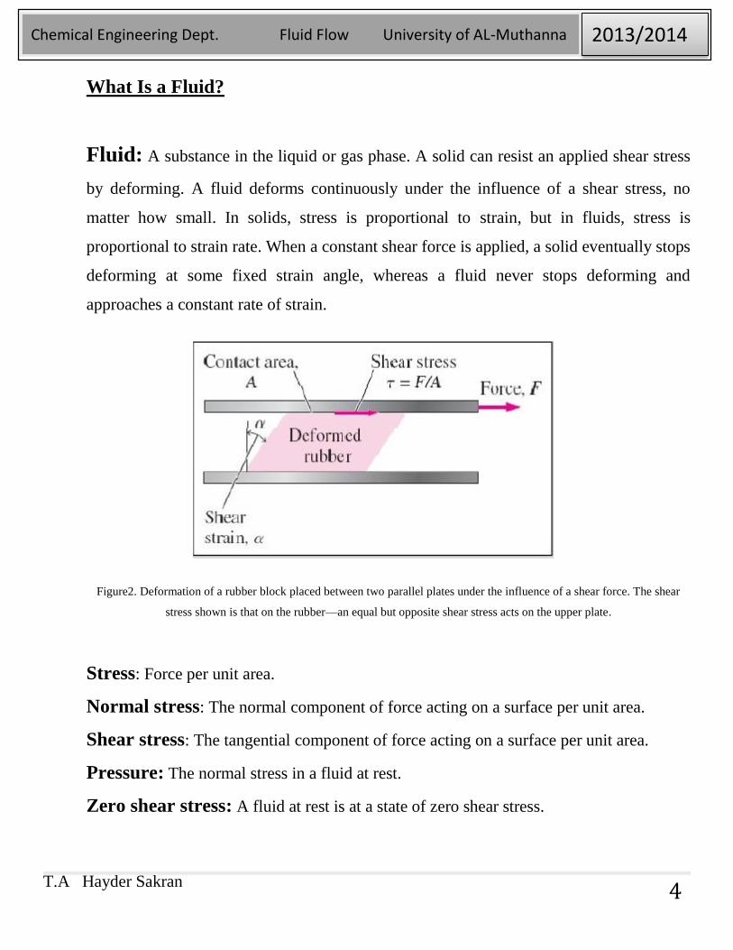
Figure2. Deformation of a rubber block placed between two parallel plates under the influence of a shear force. The shear
stress shown is that on the rubber—an equal but opposite shear stress acts on the upper plate.
Stress: Force per unit area.
Normal stress: The normal component of force acting on a surface per unit area.
Shear stress: The tangential component of force acting on a surface per unit area.
Pressure: The normal stress in a fluid at rest.
Zero shear stress: A fluid at rest is at a state of zero shear stress.
T.A Hayder Sakran
Chemical Engineering Dept. Fluid Flow University of AL-Muthanna 2013/2014
5
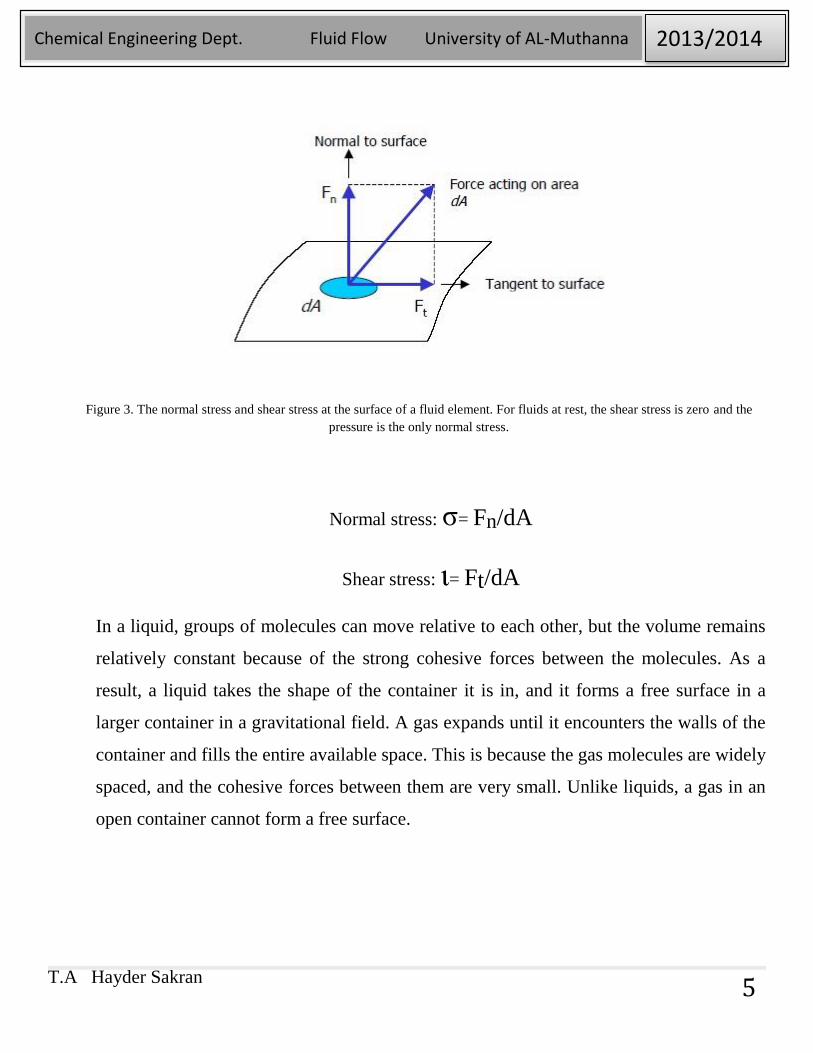
Figure 3. The normal stress and shear stress at the surface of a fluid element. For fluids at rest, the shear stress is zero and the
pressure is the only normal stress.
Normal stress: σ= Fn/dA
Shear stress: ι= Ft/dA
In a liquid, groups of molecules can move relative to each other, but the volume remains
relatively constant because of the strong cohesive forces between the molecules. As a
result, a liquid takes the shape of the container it is in, and it forms a free surface in a
larger container in a gravitational field. A gas expands until it encounters the walls of the
container and fills the entire available space. This is because the gas molecules are widely
spaced, and the cohesive forces between them are very small. Unlike liquids, a gas in an
open container cannot form a free surface.
T.A Hayder Sakran
Chemical Engineering Dept. Fluid Flow University of AL-Muthanna 2013/2014
6
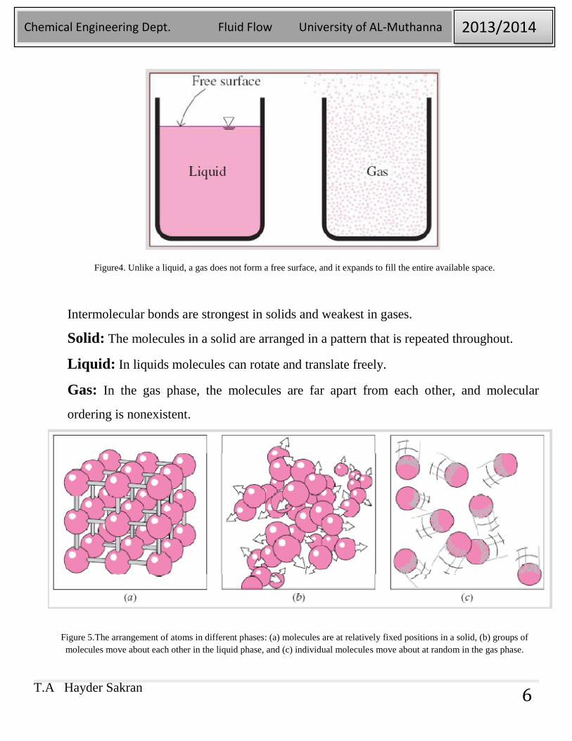
Figure4. Unlike a liquid, a gas does not form a free surface, and it expands to fill the entire available space.
Intermolecular bonds are strongest in solids and weakest in gases.
Solid: The molecules in a solid are arranged in a pattern that is repeated throughout.
Liquid: In liquids molecules can rotate and translate freely.
Gas: In the gas phase, the molecules are far apart from each other, and molecular
ordering is nonexistent.
Figure 5.The arrangement of atoms in different phases: (a) molecules are at relatively fixed positions in a solid, (b) groups of
molecules move about each other in the liquid phase, and (c) individual molecules move about at random in the gas phase.
T.A Hayder Sakran
Chemical Engineering Dept. Fluid Flow University of AL-Muthanna 2013/2014
7
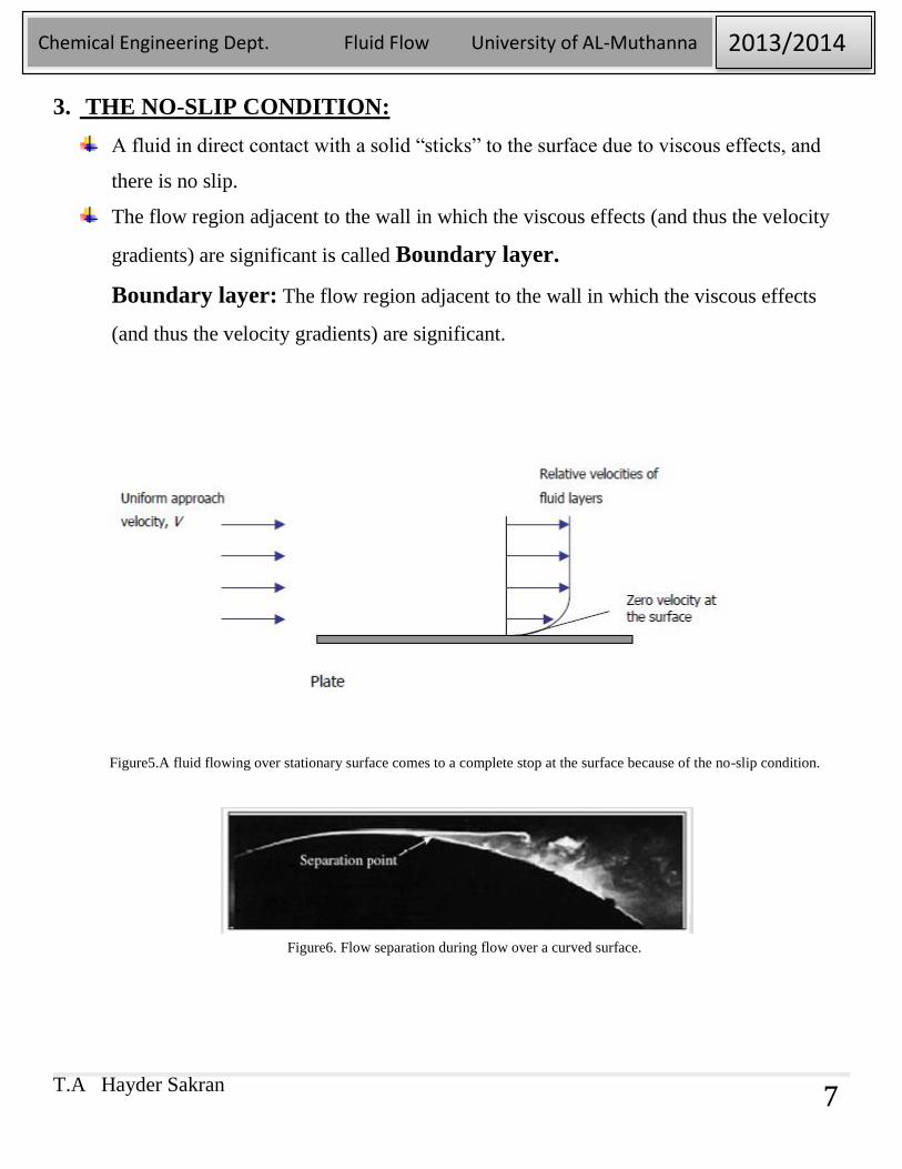
3. THE NO-SLIP CONDITION:
A fluid in direct contact with a solid “sticks” to the surface due to viscous effects, and
there is no slip.
The flow region adjacent to the wall in which the viscous effects (and thus the velocity
gradients) are significant is called Boundary layer.
Boundary layer: The flow region adjacent to the wall in which the viscous effects
(and thus the velocity gradients) are significant.
Figure5.A fluid flowing over stationary surface comes to a complete stop at the surface because of the no-slip condition.
Figure6. Flow separation during flow over a curved surface.
T.A Hayder Sakran
Chemical Engineering Dept. Fluid Flow University of AL-Muthanna 2013/2014
8
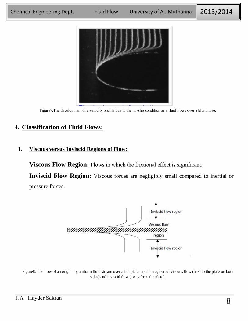
Figure7.The development of a velocity profile due to the no-slip condition as a fluid flows over a blunt nose.
4. Classification of Fluid Flows:
I. Viscous versus Inviscid Regions of Flow:
Viscous Flow Region: Flows in which the frictional effect is significant.
Inviscid Flow Region: Viscous forces are negligibly small compared to inertial or
pressure forces.
Figure8. The flow of an originally uniform fluid stream over a flat plate, and the regions of viscous flow (next to the plate on both
sides) and inviscid flow (away from the plate).

T.A Hayder Sakran
Chemical Engineering Dept. Fluid Flow University of AL-Muthanna 2013/2014
9
II. Internal versus External Flow
External flow: Flows in which the fluid is completely unbounded by solid surface.
e.g. flow over a plate, a wire, or a pipe..
Dominated by the influence of viscosity throughout the flow field
Internal flow: Flows in which the fluid is completely bounded by solid surface.
e.g. flow in a pipe or duct
Viscous effects are limited to boundary layers near solid surfaces and to wake regions
downstream of bodies
Open-channel flow: The flow of liquids in a duct in which the liquid is partially filled
and there is a free surface.
e.g. rivers, irrigation channels
Figure9. External flow over a tennis ball, and the turbulent wake region behind.
T.A Hayder Sakran
Chemical Engineering Dept. Fluid Flow University of AL-Muthanna 2013/2014
10
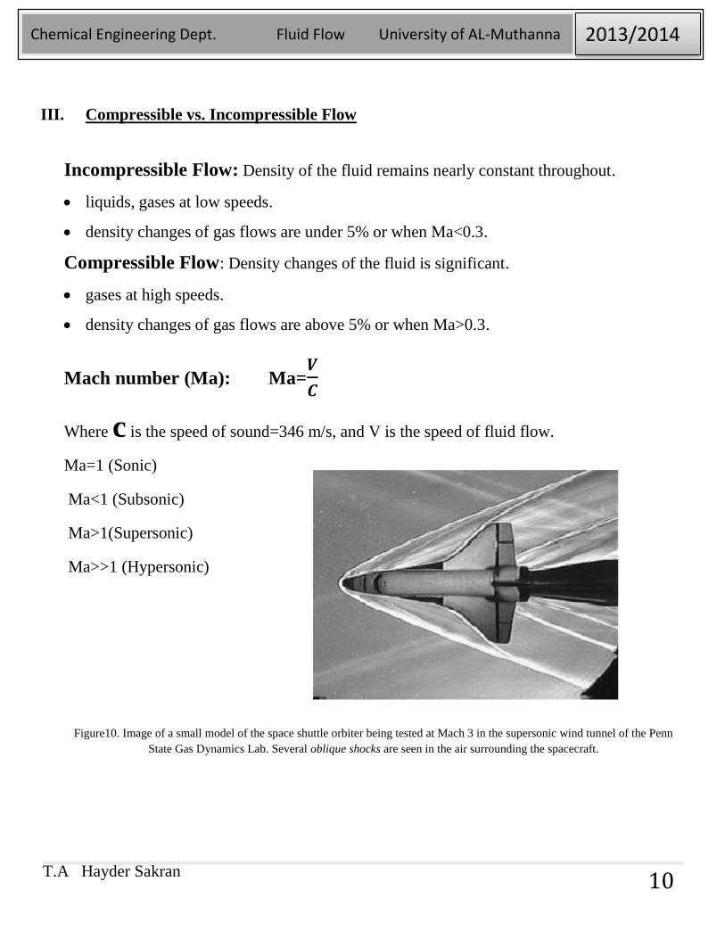
III. Compressible vs. Incompressible Flow
Incompressible Flow: Density of the fluid remains nearly constant throughout.
liquids, gases at low speeds.
density changes of gas flows are under 5% or when Ma<0.3.
Compressible Flow: Density changes of the fluid is significant.
gases at high speeds.
density changes of gas flows are above 5% or when Ma>0.3.
Mach number (Ma): Ma=𝑽
𝑪
Where c is the speed of sound=346 m/s, and V is the speed of fluid flow.
Ma=1 (Sonic)
Ma<1 (Subsonic)
Ma>1(Supersonic)
Ma>>1 (Hypersonic)
Figure10. Image of a small model of the space shuttle orbiter being tested at Mach 3 in the supersonic wind tunnel of the Penn
State Gas Dynamics Lab. Several oblique shocks are seen in the air surrounding the spacecraft.
T.A Hayder Sakran
Chemical Engineering Dept. Fluid Flow University of AL-Muthanna 2013/2014
11
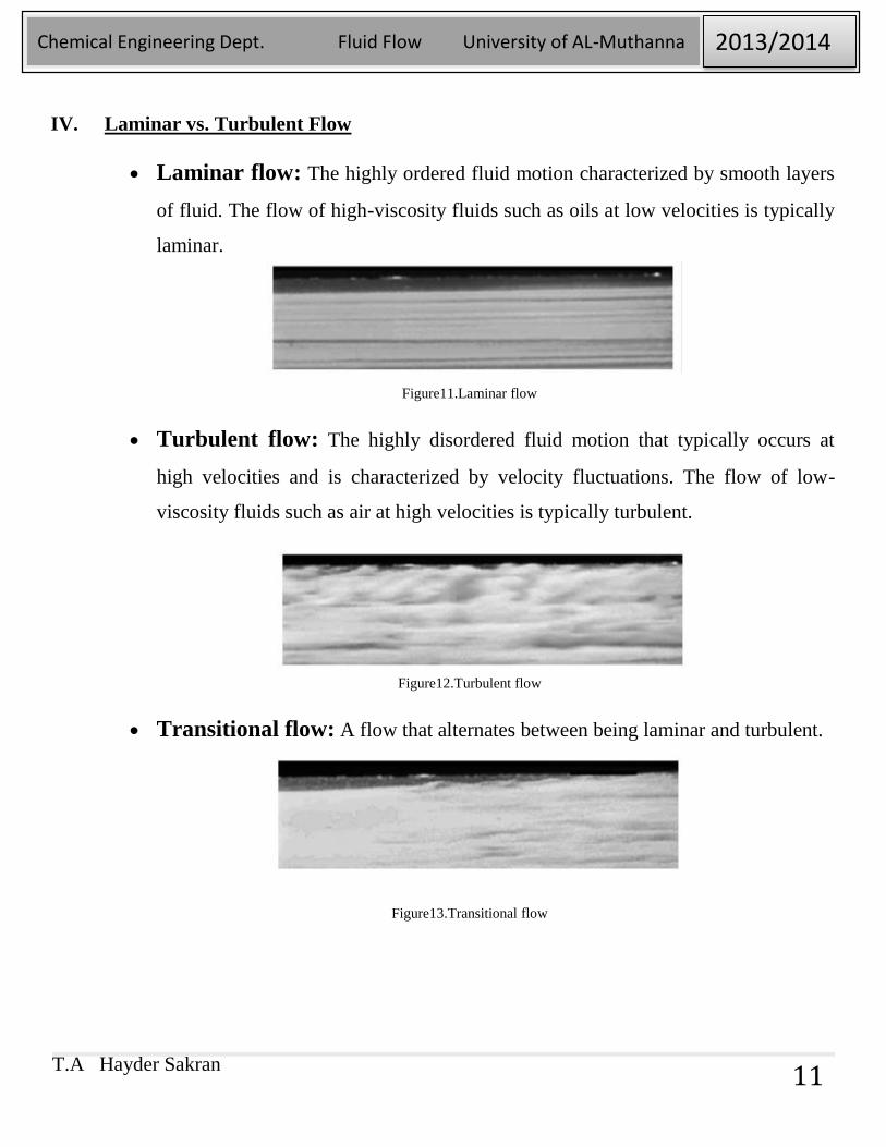
IV. Laminar vs. Turbulent Flow
Laminar flow: The highly ordered fluid motion characterized by smooth layers
of fluid. The flow of high-viscosity fluids such as oils at low velocities is typically
laminar.
Figure11.Laminar flow
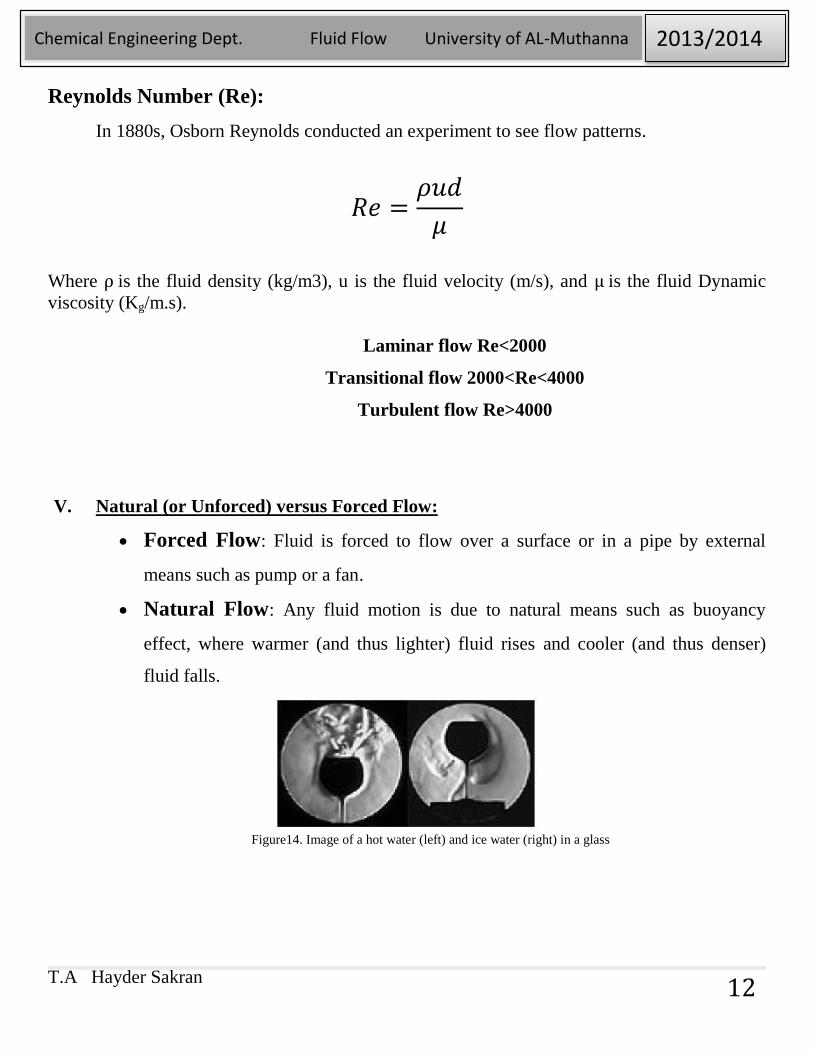
Turbulent flow: The highly disordered fluid motion that typically occurs at
high velocities and is characterized by velocity fluctuations. The flow of low-
viscosity fluids such as air at high velocities is typically turbulent.
Figure12.Turbulent flow
Transitional flow: A flow that alternates between being laminar and turbulent.
Figure13.Transitional flow
T.A Hayder Sakran
Chemical Engineering Dept. Fluid Flow University of AL-Muthanna 2013/2014
12
Reynolds Number (Re):
In 1880s, Osborn Reynolds conducted an experiment to see flow patterns.
𝑅𝑒 =𝜌𝑢𝑑
𝜇
Where ρ is the fluid density (kg/m3), u is the fluid velocity (m/s), and μ is the fluid Dynamic
viscosity (Kg/m.s).
Laminar flow Re<2000
Transitional flow 2000<Re<4000
Turbulent flow Re>4000
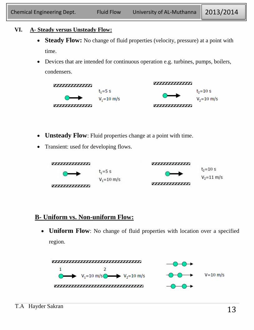
V. Natural (or Unforced) versus Forced Flow:
Forced Flow: Fluid is forced to flow over a surface or in a pipe by external
means such as pump or a fan.
Natural Flow: Any fluid motion is due to natural means such as buoyancy
effect, where warmer (and thus lighter) fluid rises and cooler (and thus denser)
fluid falls.
Figure14. Image of a hot water (left) and ice water (right) in a glass
T.A Hayder Sakran
Chemical Engineering Dept. Fluid Flow University of AL-Muthanna 2013/2014
13
VI. A- Steady versus Unsteady Flow:
Steady Flow: No change of fluid properties (velocity, pressure) at a point with
time.
Devices that are intended for continuous operation e.g. turbines, pumps, boilers,
condensers.
Unsteady Flow: Fluid properties change at a point with time.
Transient: used for developing flows.
B- Uniform vs. Non-uniform Flow:
Uniform Flow: No change of fluid properties with location over a specified
region.
T.A Hayder Sakran
Chemical Engineering Dept. Fluid Flow University of AL-Muthanna 2013/2014
14
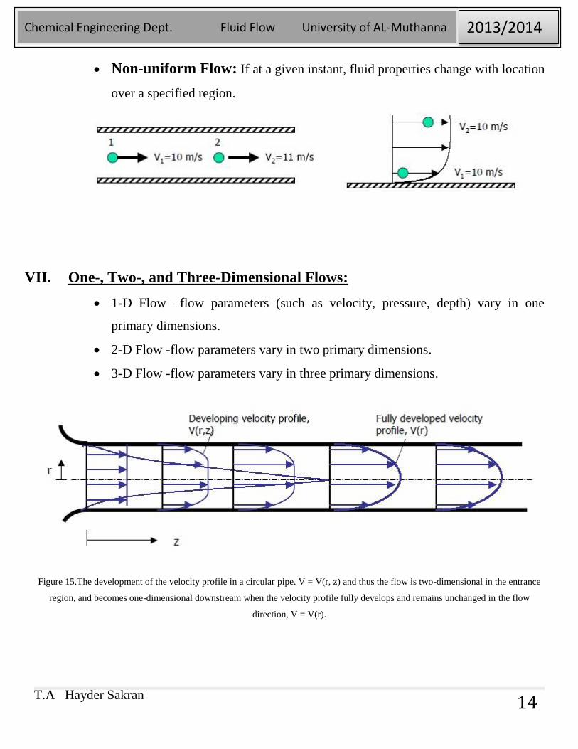
Non-uniform Flow: If at a given instant, fluid properties change with location
over a specified region.
VII. One-, Two-, and Three-Dimensional Flows:
1-D Flow –flow parameters (such as velocity, pressure, depth) vary in one
primary dimensions.
2-D Flow -flow parameters vary in two primary dimensions.
3-D Flow -flow parameters vary in three primary dimensions.
Figure 15.The development of the velocity profile in a circular pipe. V = V(r, z) and thus the flow is two-dimensional in the entrance
region, and becomes one-dimensional downstream when the velocity profile fully develops and remains unchanged in the flow
direction, V = V(r).
T.A Hayder Sakran
Chemical Engineering Dept. Fluid Flow University of AL-Muthanna 2013/2014
15
5. SYSTEM AND CONTROL VOLUME:
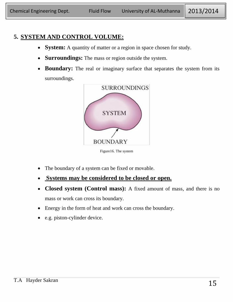
System: A quantity of matter or a region in space chosen for study.
Surroundings: The mass or region outside the system.
Boundary: The real or imaginary surface that separates the system from its
surroundings.
Figure16. The system
The boundary of a system can be fixed or movable.
Systems may be considered to be closed or open.
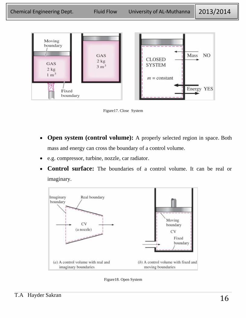
Closed system (Control mass): A fixed amount of mass, and there is no
mass or work can cross its boundary.
Energy in the form of heat and work can cross the boundary.
e.g. piston-cylinder device.
T.A Hayder Sakran
Chemical Engineering Dept. Fluid Flow University of AL-Muthanna 2013/2014
16
Figure17. Close System
Open system (control volume): A properly selected region in space. Both
mass and energy can cross the boundary of a control volume.
e.g. compressor, turbine, nozzle, car radiator.
Control surface: The boundaries of a control volume. It can be real or
imaginary.
Figure18. Open System
T.A Hayder Sakran
Chemical Engineering Dept. Fluid Flow University of AL-Muthanna 2013/2014
17
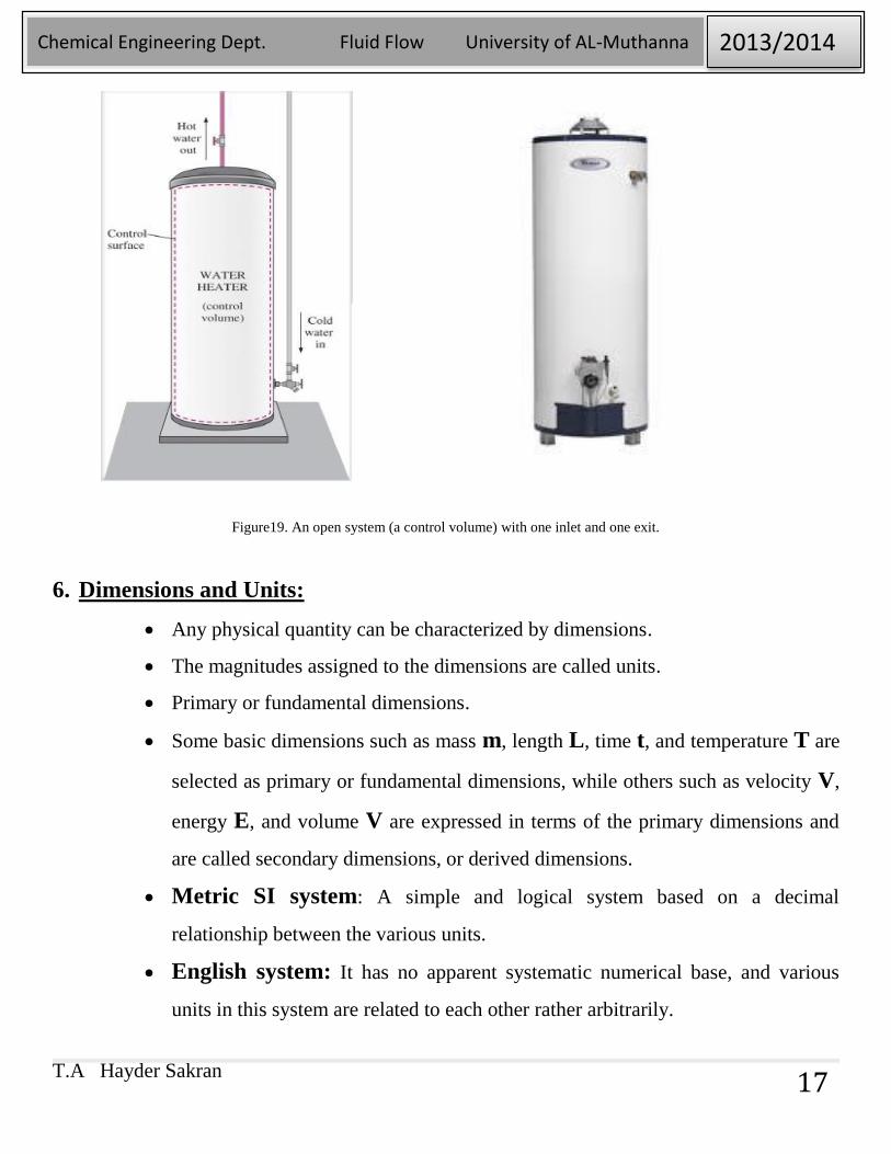
Figure19. An open system (a control volume) with one inlet and one exit.
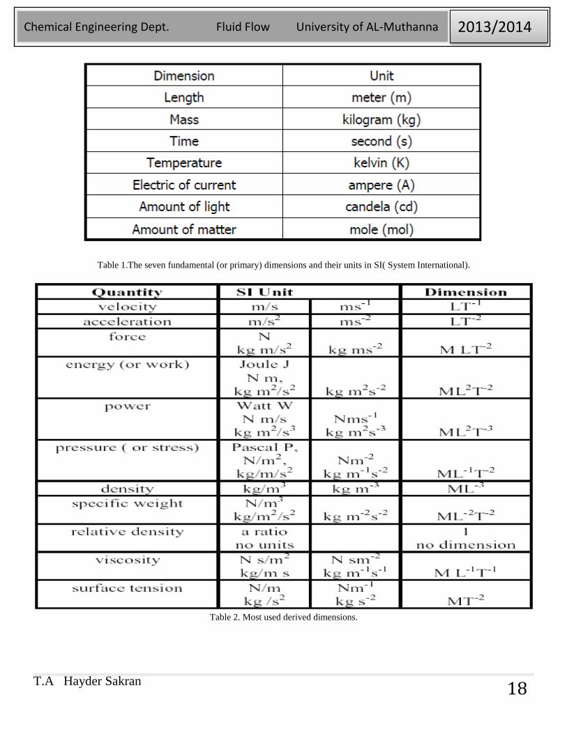
6. Dimensions and Units:
Any physical quantity can be characterized by dimensions.
The magnitudes assigned to the dimensions are called units.
Primary or fundamental dimensions.
Some basic dimensions such as mass m, length L, time t, and temperature T are
selected as primary or fundamental dimensions, while others such as velocity V,
energy E, and volume V are expressed in terms of the primary dimensions and
are called secondary dimensions, or derived dimensions.
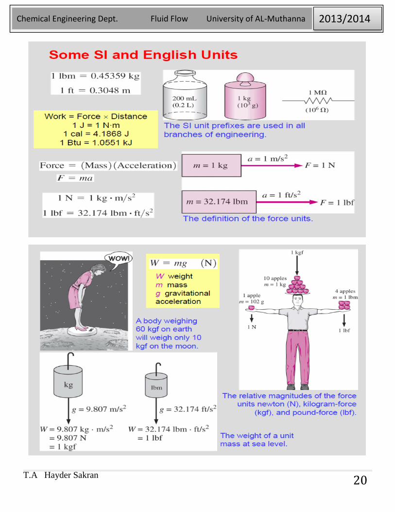
Metric SI system: A simple and logical system based on a decimal
relationship between the various units.
English system: It has no apparent systematic numerical base, and various
units in this system are related to each other rather arbitrarily.
T.A Hayder Sakran
Chemical Engineering Dept. Fluid Flow University of AL-Muthanna 2013/2014
18
Table 1.The seven fundamental (or primary) dimensions and their units in SI( System International).
Table 2. Most used derived dimensions.

T.A Hayder Sakran
Chemical Engineering Dept. Fluid Flow University of AL-Muthanna 2013/2014
19
Table 3. Standard Prefix in SI Units.
T.A Hayder Sakran
Chemical Engineering Dept. Fluid Flow University of AL-Muthanna 2013/2014
20
T.A Hayder Sakran
Chemical Engineering Dept. Fluid Flow University of AL-Muthanna 2013/2014
21
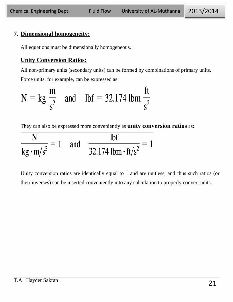
7. Dimensional homogeneity:
All equations must be dimensionally homogeneous.
Unity Conversion Ratios:
All non-primary units (secondary units) can be formed by combinations of primary units.
Force units, for example, can be expressed as:
They can also be expressed more conveniently as unity conversion ratios as:
Unity conversion ratios are identically equal to 1 and are unitless, and thus such ratios (or
their inverses) can be inserted conveniently into any calculation to properly convert units.
T.A Hayder Sakran
Chemical Engineering Dept. Fluid Flow University of AL-Muthanna 2013/2014
22
Problems
1-1. Define internal, external, and open-channel flows.
1-2. Define incompressible and compressible flow.
1-3. Define the no-slip condition.
1-4. Define forced flow and discuss the difference between forced and natural flow.
1-5. Define the boundary layer.
1-6. Define system, surroundings, and boundary.
T.A Hayder Sakran
Chemical Engineering Dept. Fluid Flow University of AL-Muthanna 2013/2014
23
Chapter 2
PROPERTIES OF FLUIDS
Objectives
2-1. Introduction
2-2. Density and Specific Gravity
Density of Ideal Gases
2-3. Viscosity
Viscosity measurement
2-4. Surface Tension and Capillary Effect
T.A Hayder Sakran
Chemical Engineering Dept. Fluid Flow University of AL-Muthanna 2013/2014
24
1- INTRODUCTION:
• Property: Any characteristic of a system.
• Some familiar properties are pressure P, temperature T, volume V and mass m
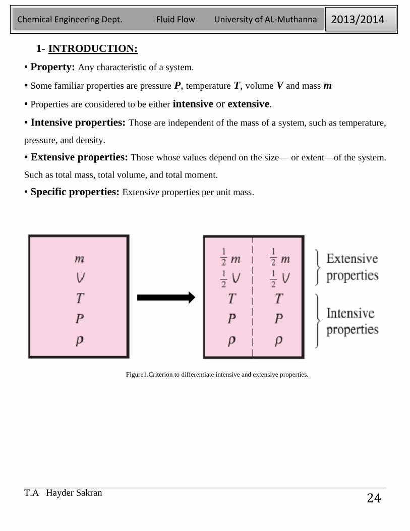
• Properties are considered to be either intensive or extensive.
• Intensive properties: Those are independent of the mass of a system, such as temperature,
pressure, and density.
• Extensive properties: Those whose values depend on the size— or extent—of the system.
Such as total mass, total volume, and total moment.
• Specific properties: Extensive properties per unit mass.
Figure1.Criterion to differentiate intensive and extensive properties.
T.A Hayder Sakran
Chemical Engineering Dept. Fluid Flow University of AL-Muthanna 2013/2014
25
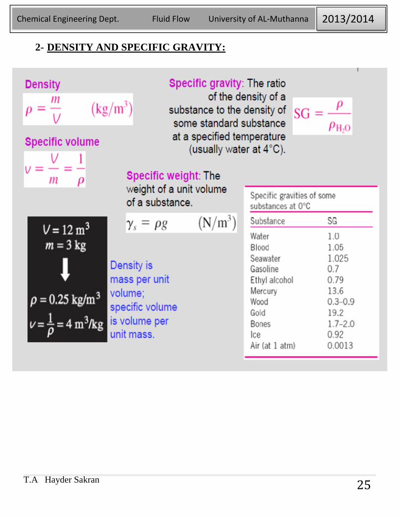
2- DENSITY AND SPECIFIC GRAVITY:
T.A Hayder Sakran
Chemical Engineering Dept. Fluid Flow University of AL-Muthanna 2013/2014
26
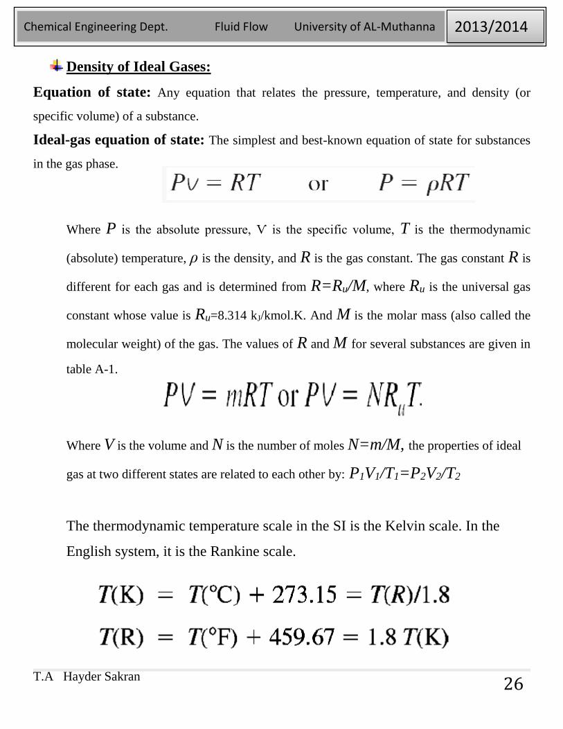
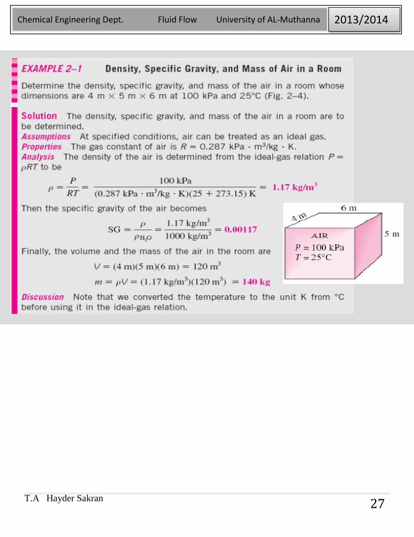
Density of Ideal Gases:
Equation of state: Any equation that relates the pressure, temperature, and density (or
specific volume) of a substance.
Ideal-gas equation of state: The simplest and best-known equation of state for substances
in the gas phase.
Where P is the absolute pressure, Ѵ is the specific volume, T is the thermodynamic
(absolute) temperature, ρ is the density, and R is the gas constant. The gas constant R is
different for each gas and is determined from R=Ru/M, where Ru is the universal gas
constant whose value is Ru=8.314 kJ/kmol.K. And M is the molar mass (also called the
molecular weight) of the gas. The values of R and M for several substances are given in
table A-1.
Where V is the volume and N is the number of moles N=m/M, the properties of ideal
gas at two different states are related to each other by: P1V1/T1=P2V2/T2
The thermodynamic temperature scale in the SI is the Kelvin scale. In the
English system, it is the Rankine scale.
T.A Hayder Sakran
Chemical Engineering Dept. Fluid Flow University of AL-Muthanna 2013/2014
27
T.A Hayder Sakran
Chemical Engineering Dept. Fluid Flow University of AL-Muthanna 2013/2014
28
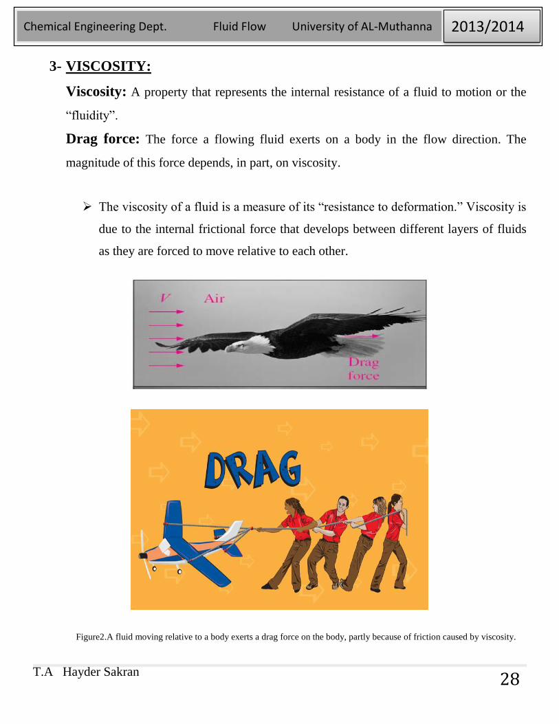
3- VISCOSITY:
Viscosity: A property that represents the internal resistance of a fluid to motion or the
“fluidity”.
Drag force: The force a flowing fluid exerts on a body in the flow direction. The
magnitude of this force depends, in part, on viscosity.
The viscosity of a fluid is a measure of its “resistance to deformation.” Viscosity is
due to the internal frictional force that develops between different layers of fluids
as they are forced to move relative to each other.
Figure2.A fluid moving relative to a body exerts a drag force on the body, partly because of friction caused by viscosity.
T.A Hayder Sakran
Chemical Engineering Dept. Fluid Flow University of AL-Muthanna 2013/2014
29
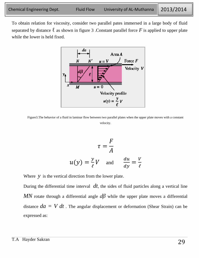
To obtain relation for viscosity, consider two parallel pates immersed in a large body of fluid
separated by distance ℓ as shown in figure 3 .Constant parallel force F is applied to upper plate
while the lower is held fixed.
Figure3.The behavior of a fluid in laminar flow between two parallel plates when the upper plate moves with a constant
velocity.
𝜏 =𝐹
𝐴
𝑢(𝑦) =𝑦
ℓ𝑉 and
𝑑𝑢
𝑑𝑦=
𝑉
ℓ
Where y is the vertical direction from the lower plate.
During the differential time interval dt, the sides of fluid particles along a vertical line
MN rotate through a differential angle dβ while the upper plate moves a differential
distance da = V dt . The angular displacement or deformation (Shear Strain) can be
expressed as:
T.A Hayder Sakran
Chemical Engineering Dept. Fluid Flow University of AL-Muthanna 2013/2014
30
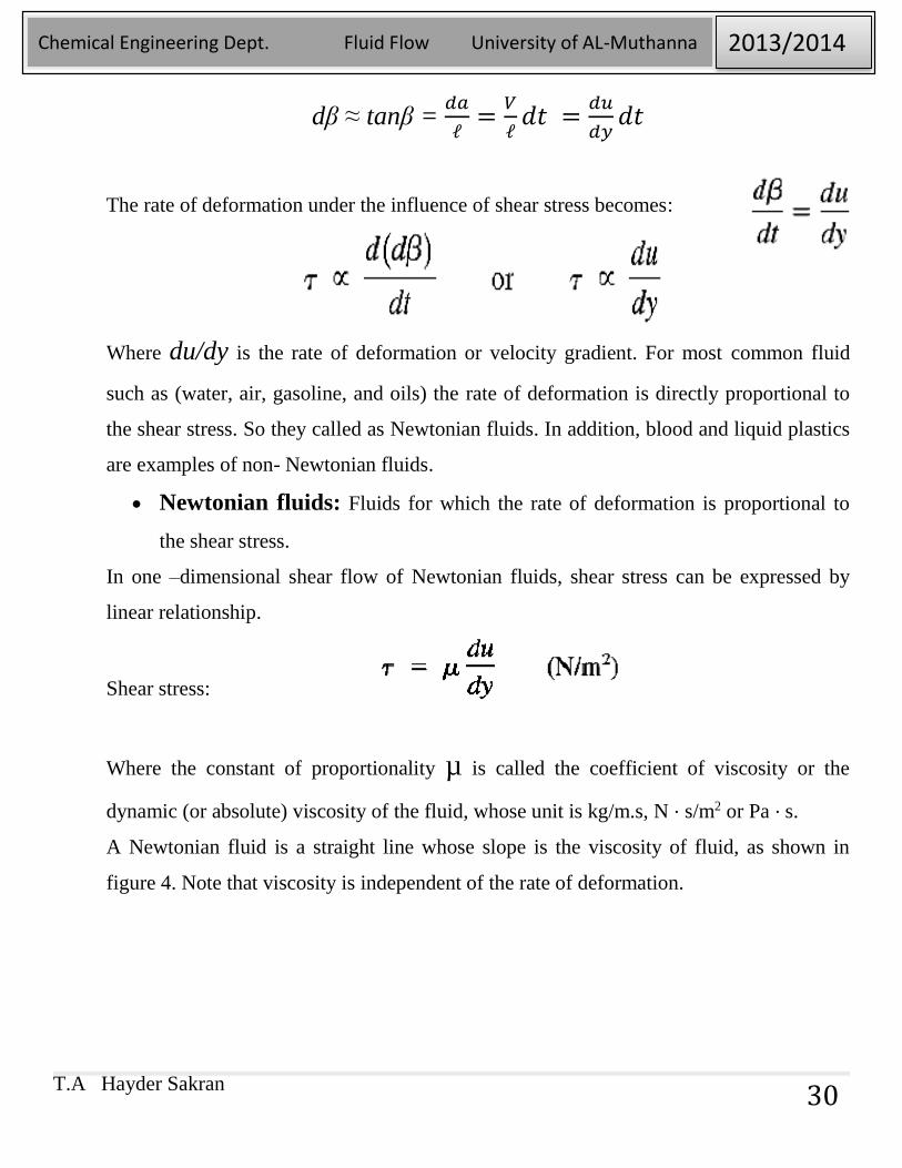
dβ ≈ tanβ = 𝑑𝑎
ℓ=
𝑉
ℓ𝑑𝑡 =
𝑑𝑢
𝑑𝑦𝑑𝑡
The rate of deformation under the influence of shear stress becomes:
Where du/dy is the rate of deformation or velocity gradient. For most common fluid
such as (water, air, gasoline, and oils) the rate of deformation is directly proportional to
the shear stress. So they called as Newtonian fluids. In addition, blood and liquid plastics
are examples of non- Newtonian fluids.
Newtonian fluids: Fluids for which the rate of deformation is proportional to
the shear stress.
In one –dimensional shear flow of Newtonian fluids, shear stress can be expressed by
linear relationship.
Shear stress:
Where the constant of proportionality µ is called the coefficient of viscosity or the
dynamic (or absolute) viscosity of the fluid, whose unit is kg/m.s, N ⋅ s/m2 or Pa ⋅ s.
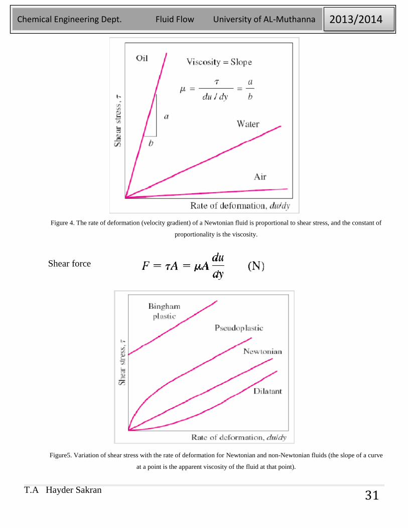
A Newtonian fluid is a straight line whose slope is the viscosity of fluid, as shown in
figure 4. Note that viscosity is independent of the rate of deformation.
T.A Hayder Sakran
Chemical Engineering Dept. Fluid Flow University of AL-Muthanna 2013/2014
31
Figure 4. The rate of deformation (velocity gradient) of a Newtonian fluid is proportional to shear stress, and the constant of
proportionality is the viscosity.
Shear force
Figure5. Variation of shear stress with the rate of deformation for Newtonian and non-Newtonian fluids (the slope of a curve
at a point is the apparent viscosity of the fluid at that point).
T.A Hayder Sakran
Chemical Engineering Dept. Fluid Flow University of AL-Muthanna 2013/2014
32
In fluid mechanics and heat transfer, the ratio of dynamic viscosity to density appears
frequently. This ratio is given the name Kinematic viscosity ν and is expressed as:
ν = µ/ρ and its unit is m2/s or stoke1 stoke = 1 cm2/s.
In general, the viscosity of a fluid depends on both temperature and pressure, although
the dependence on pressure is rather weak.
For liquids, both the dynamic and kinematic viscosities are practically
independent of pressure, and any small variation with pressure is usually
disregarded, except at extremely high pressures.
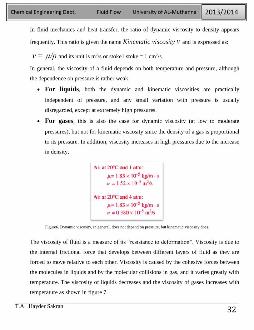
For gases, this is also the case for dynamic viscosity (at low to moderate
pressures), but not for kinematic viscosity since the density of a gas is proportional
to its pressure. In addition, viscosity increases in high pressures due to the increase
in density.
Figure6. Dynamic viscosity, in general, does not depend on pressure, but kinematic viscosity does.
The viscosity of fluid is a measure of its “resistance to deformation”. Viscosity is due to
the internal frictional force that develops between different layers of fluid as they are
forced to move relative to each other. Viscosity is caused by the cohesive forces between
the molecules in liquids and by the molecular collisions in gas, and it varies greatly with
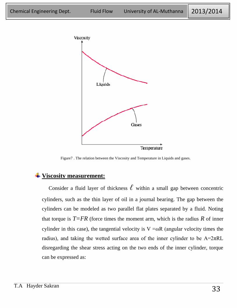
temperature. The viscosity of liquids decreases and the viscosity of gases increases with
temperature as shown in figure 7.
T.A Hayder Sakran
Chemical Engineering Dept. Fluid Flow University of AL-Muthanna 2013/2014
33
Figure7 . The relation between the Viscosity and Temperature in Liquids and gases.
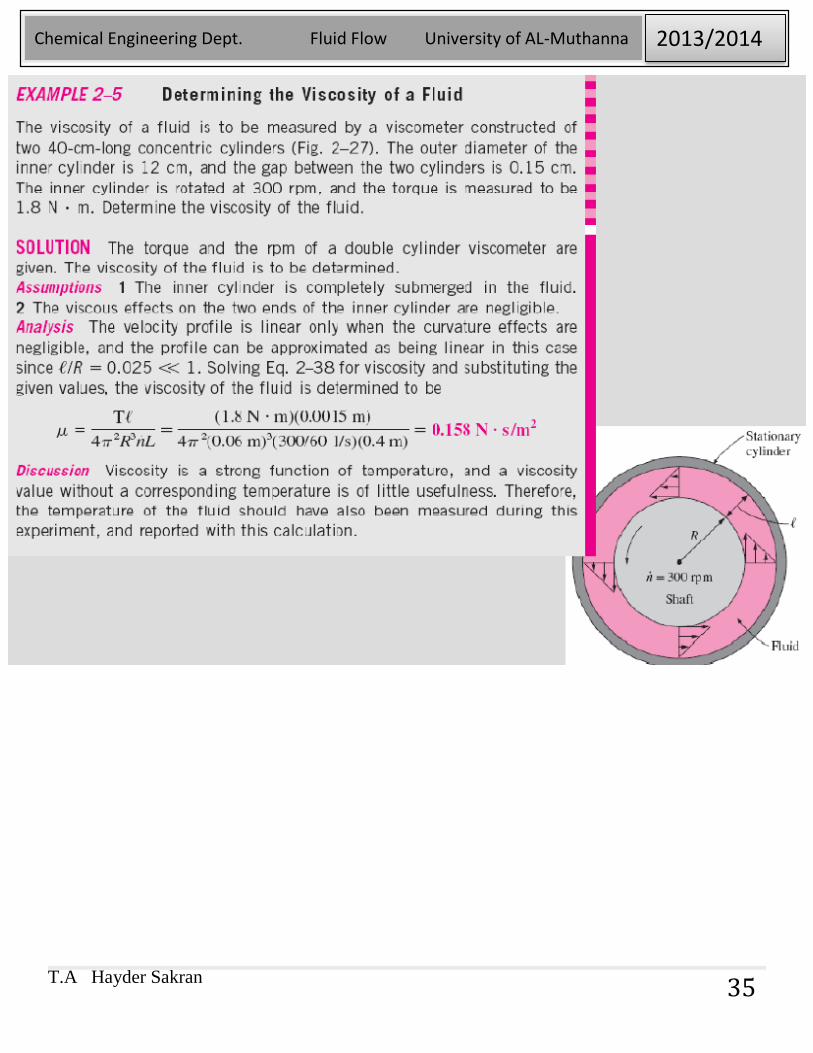
Viscosity measurement:
Consider a fluid layer of thickness ℓ within a small gap between concentric
cylinders, such as the thin layer of oil in a journal bearing. The gap between the
cylinders can be modeled as two parallel flat plates separated by a fluid. Noting
that torque is T=FR (force times the moment arm, which is the radius R of inner
cylinder in this case), the tangential velocity is V =ωR (angular velocity times the
radius), and taking the wetted surface area of the inner cylinder to be A=2πRL
disregarding the shear stress acting on the two ends of the inner cylinder, torque
can be expressed as:
T.A Hayder Sakran
Chemical Engineering Dept. Fluid Flow University of AL-Muthanna 2013/2014
34
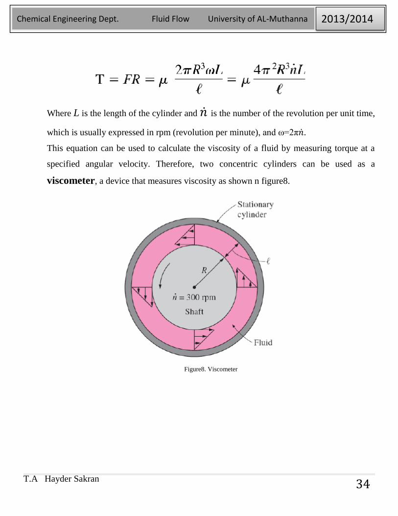
Where L is the length of the cylinder and �̇� is the number of the revolution per unit time,
which is usually expressed in rpm (revolution per minute), and ω=2π�̇�.
This equation can be used to calculate the viscosity of a fluid by measuring torque at a
specified angular velocity. Therefore, two concentric cylinders can be used as a
viscometer, a device that measures viscosity as shown n figure8.
Figure8. Viscometer
T.A Hayder Sakran
Chemical Engineering Dept. Fluid Flow University of AL-Muthanna 2013/2014
35
T.A Hayder Sakran
Chemical Engineering Dept. Fluid Flow University of AL-Muthanna 2013/2014
36
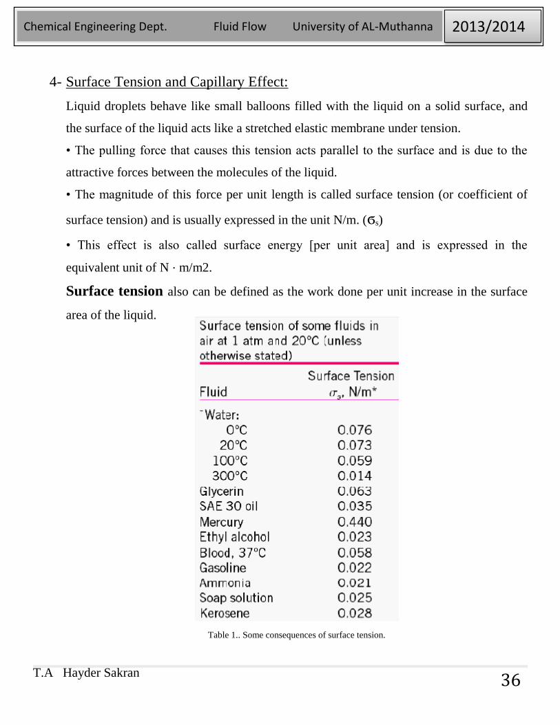
4- Surface Tension and Capillary Effect:
Liquid droplets behave like small balloons filled with the liquid on a solid surface, and
the surface of the liquid acts like a stretched elastic membrane under tension.
• The pulling force that causes this tension acts parallel to the surface and is due to the
attractive forces between the molecules of the liquid.
• The magnitude of this force per unit length is called surface tension (or coefficient of
surface tension) and is usually expressed in the unit N/m. (ϭs)
• This effect is also called surface energy [per unit area] and is expressed in the
equivalent unit of N ⋅ m/m2.
Surface tension also can be defined as the work done per unit increase in the surface
area of the liquid.
Table 1.. Some consequences of surface tension.
T.A Hayder Sakran
Chemical Engineering Dept. Fluid Flow University of AL-Muthanna 2013/2014
37
Capillary Effect:
Capillary effect: The rise or fall of a liquid in a small-diameter tube inserted into the
liquid.
Capillaries: Such narrow tubes or confined flow channels. The capillary effect is
partially responsible for the rise of water to the top of tall trees.
Meniscus: The curved free surface of a liquid in a capillary tube.
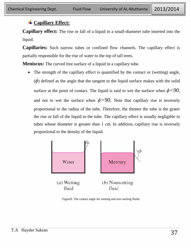
The strength of the capillary effect is quantified by the contact or (wetting) angle,
(ϕ) defined as the angle that the tangent to the liquid surface makes with the solid
surface at the point of contact. The liquid is said to wet the surface when ϕ<90,
and not to wet the surface when ϕ>90. Note that capillary rise is inversely
proportional to the radius of the tube. Therefore, the thinner the tube is the grater
the rise or fall of the liquid in the tube. The capillary effect is usually negligible in
tubes whose diameter is greater than 1 cm. In addition, capillary rise is inversely
proportional to the density of the liquid.
Figure9. The contact angle for wetting and non-wetting fluids.
T.A Hayder Sakran
Chemical Engineering Dept. Fluid Flow University of AL-Muthanna 2013/2014
38
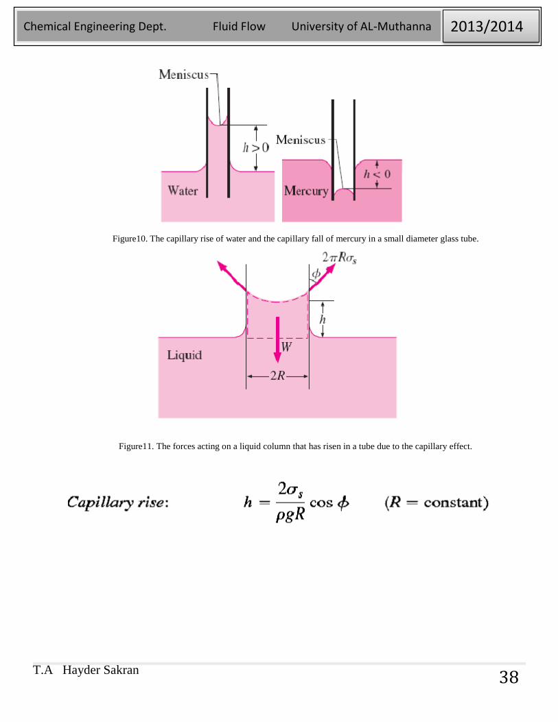
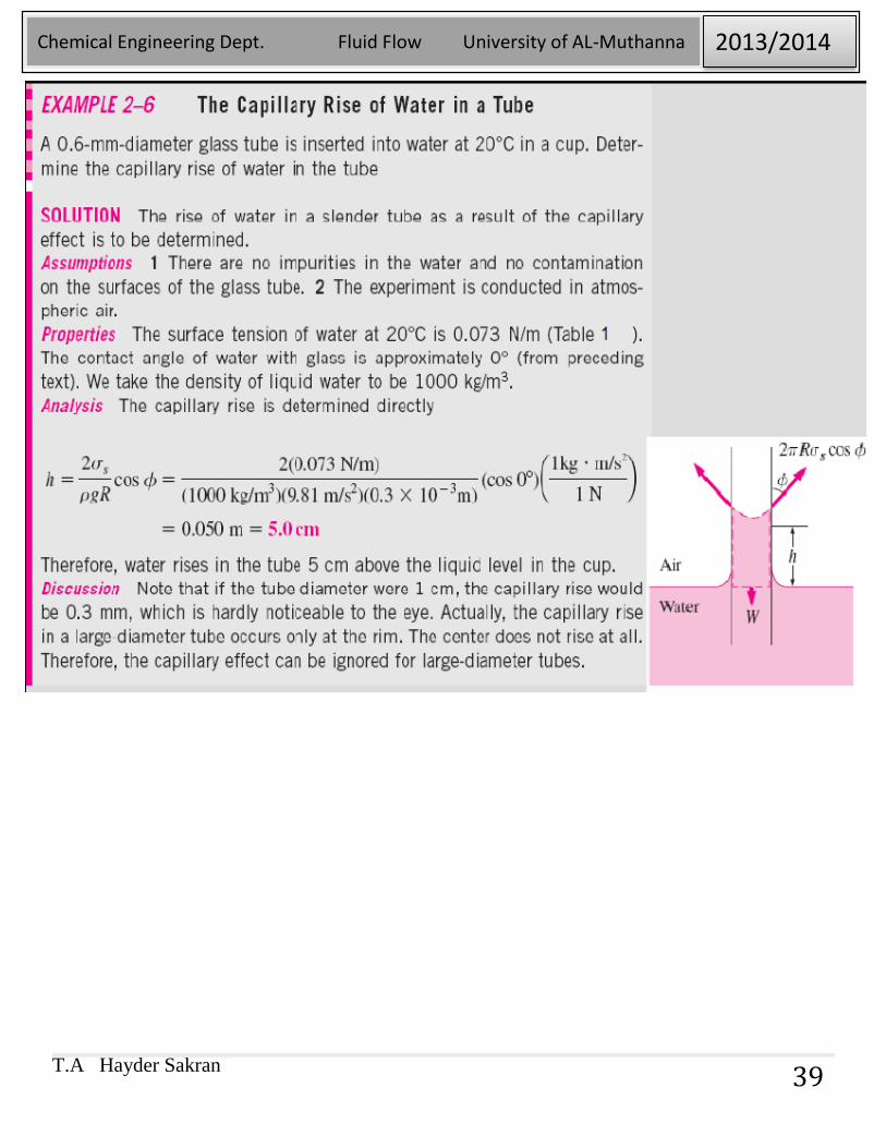
Figure10. The capillary rise of water and the capillary fall of mercury in a small diameter glass tube.
Figure11. The forces acting on a liquid column that has risen in a tube due to the capillary effect.
T.A Hayder Sakran
Chemical Engineering Dept. Fluid Flow University of AL-Muthanna 2013/2014
39
T.A Hayder Sakran
Chemical Engineering Dept. Fluid Flow University of AL-Muthanna 2013/2014
40
Chapter 3
PRESSURE AND FLUID STATICS
Objectives
Pressure
Pressure Measurement Devices
Introduction to Fluid Statics
T.A Hayder Sakran
Chemical Engineering Dept. Fluid Flow University of AL-Muthanna 2013/2014
41
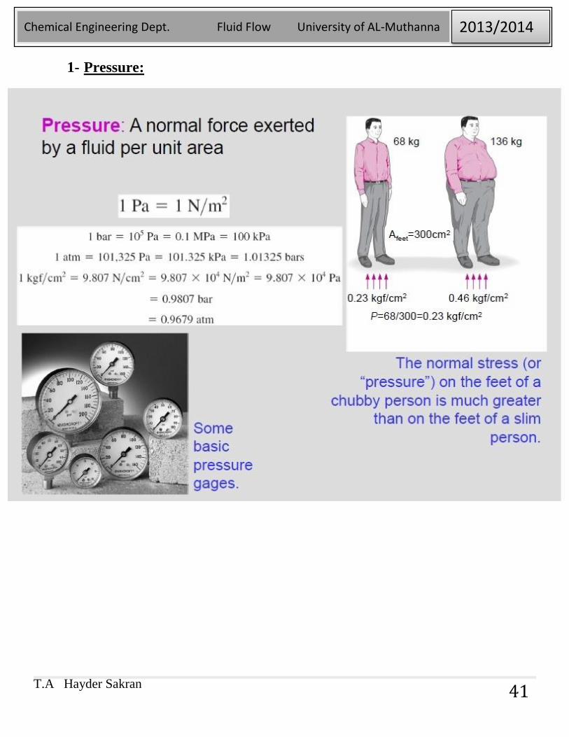
1- Pressure:
T.A Hayder Sakran
Chemical Engineering Dept. Fluid Flow University of AL-Muthanna 2013/2014
42
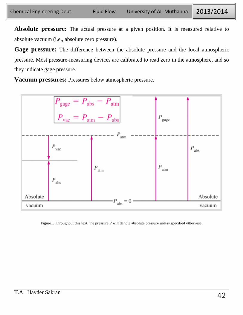
Absolute pressure: The actual pressure at a given position. It is measured relative to
absolute vacuum (i.e., absolute zero pressure).
Gage pressure: The difference between the absolute pressure and the local atmospheric
pressure. Most pressure-measuring devices are calibrated to read zero in the atmosphere, and so
they indicate gage pressure.
Vacuum pressures: Pressures below atmospheric pressure.
Figure1. Throughout this text, the pressure P will denote absolute pressure unless specified otherwise.
T.A Hayder Sakran
Chemical Engineering Dept. Fluid Flow University of AL-Muthanna 2013/2014
43
1-1. Pressure at a Point:
Pressure is the compressive force per unit area but it is not a vector. Pressure at any
point in a fluid is the same in all directions. Pressure has magnitude but not a
specific direction, and thus it is a scalar quantity.
Pressure is a scalar quantity, not a vector; the pressure at a point in a fluid is the
same in all directions.
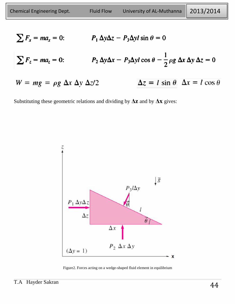
This can be domenstrated by considering a small wedge-shaped fluid element of
unit length as shown in figure 2. The mean pressures at the three surfaces are
P1,P2, and P3, and the force acting on asurface is the product of mean pressure
and the surface area. From Newton’s second law, a force balance in the x- and z-
directions gives:
Newton’s second law:The acceleration of a body is proportional to the net force acting on it
and is inversely proportional to its mass.
T.A Hayder Sakran
Chemical Engineering Dept. Fluid Flow University of AL-Muthanna 2013/2014
44
Substituting these geometric relations and dividing by Δz and by Δx gives:
Figure2. Forces acting on a wedge-shaped fluid element in equilibrium
T.A Hayder Sakran
Chemical Engineering Dept. Fluid Flow University of AL-Muthanna 2013/2014
45
Because of Δz → zero the wedge becomes infinitesimal, and thus the fluid element
shrinks to a point.
We can repeat the analysis for an element in the yz-palne and obtain a similar result.
Thus we conclude that Pressure at any point in a fluid is the same in all directions.
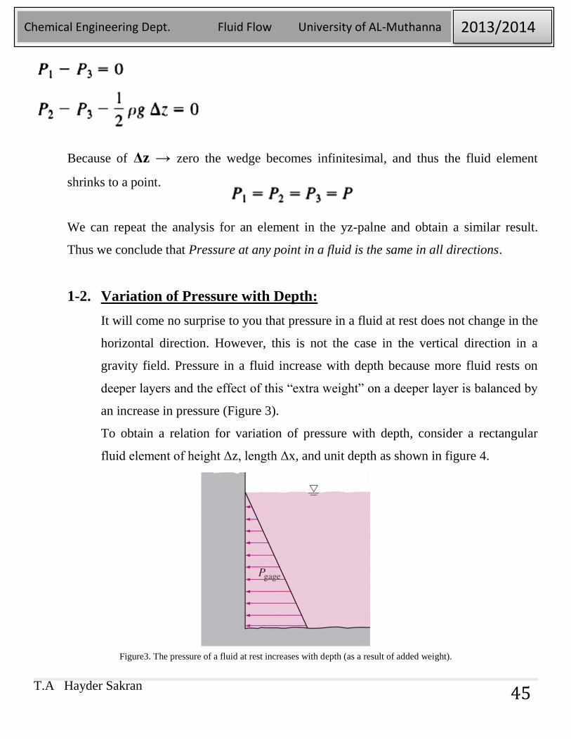
1-2. Variation of Pressure with Depth:
It will come no surprise to you that pressure in a fluid at rest does not change in the
horizontal direction. However, this is not the case in the vertical direction in a
gravity field. Pressure in a fluid increase with depth because more fluid rests on
deeper layers and the effect of this “extra weight” on a deeper layer is balanced by
an increase in pressure (Figure 3).
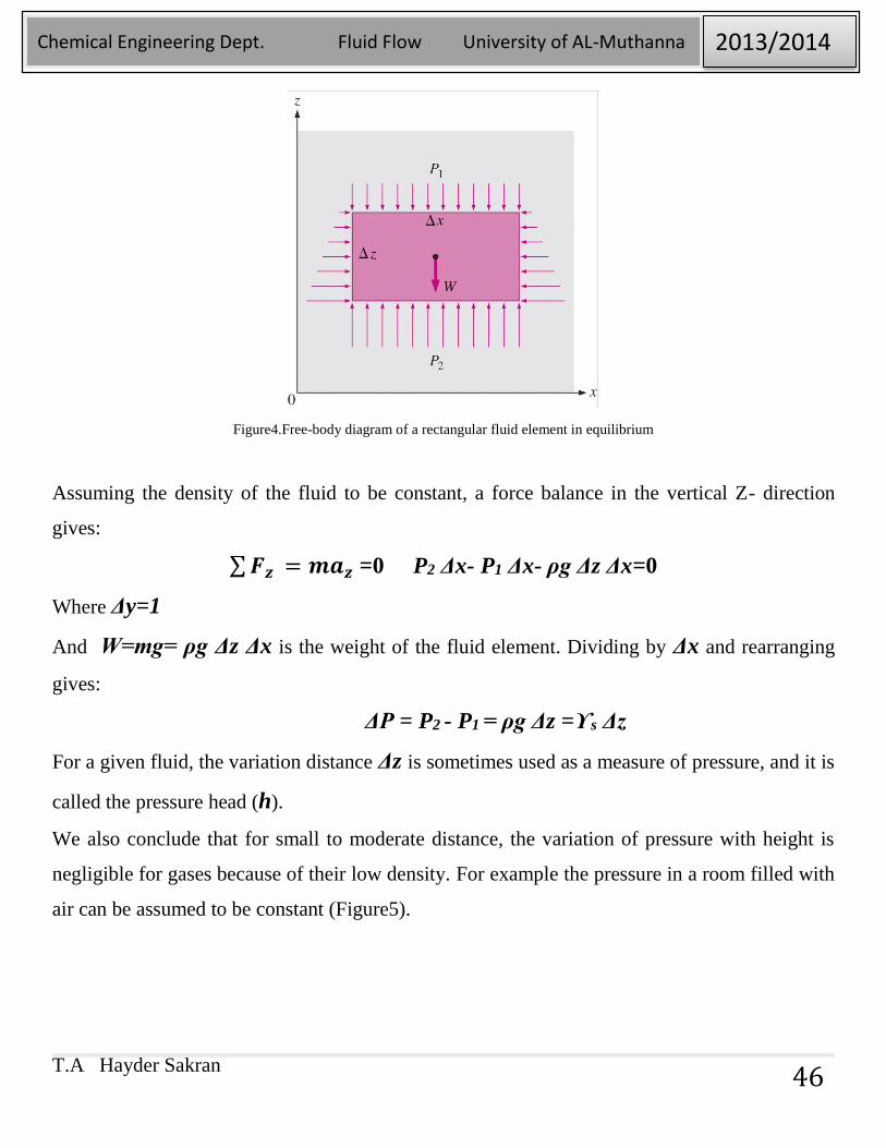
To obtain a relation for variation of pressure with depth, consider a rectangular
fluid element of height Δz, length Δx, and unit depth as shown in figure 4.
Figure3. The pressure of a fluid at rest increases with depth (as a result of added weight).
T.A Hayder Sakran
Chemical Engineering Dept. Fluid Flow University of AL-Muthanna 2013/2014
46
Figure4.Free-body diagram of a rectangular fluid element in equilibrium
Assuming the density of the fluid to be constant, a force balance in the vertical Z- direction
gives:
∑𝑭𝒛 = 𝒎𝒂𝒛 =0 P2 Δx- P1 Δx- ρg Δz Δx=0
Where Δy=1
And W=mg= ρg Δz Δx is the weight of the fluid element. Dividing by Δx and rearranging
gives:
ΔP = P2 - P1 = ρg Δz =ϒs Δz
For a given fluid, the variation distance Δz is sometimes used as a measure of pressure, and it is
called the pressure head (h).
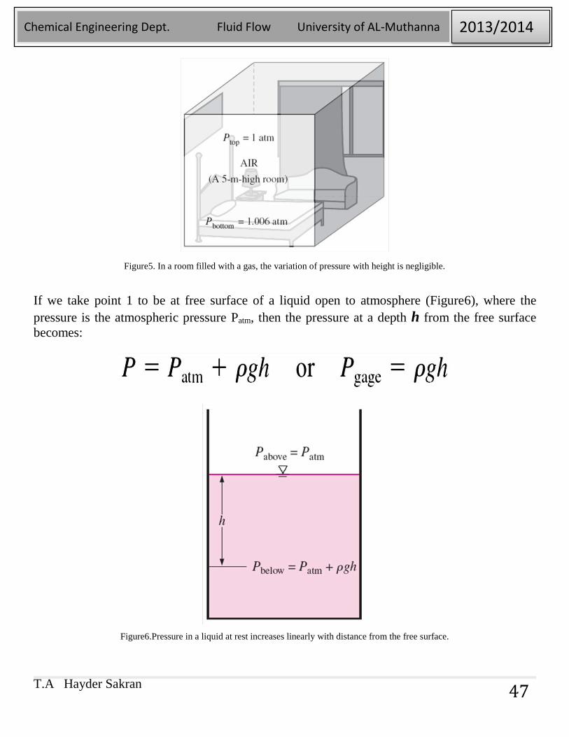
We also conclude that for small to moderate distance, the variation of pressure with height is
negligible for gases because of their low density. For example the pressure in a room filled with
air can be assumed to be constant (Figure5).
T.A Hayder Sakran
Chemical Engineering Dept. Fluid Flow University of AL-Muthanna 2013/2014
47
Figure5. In a room filled with a gas, the variation of pressure with height is negligible.
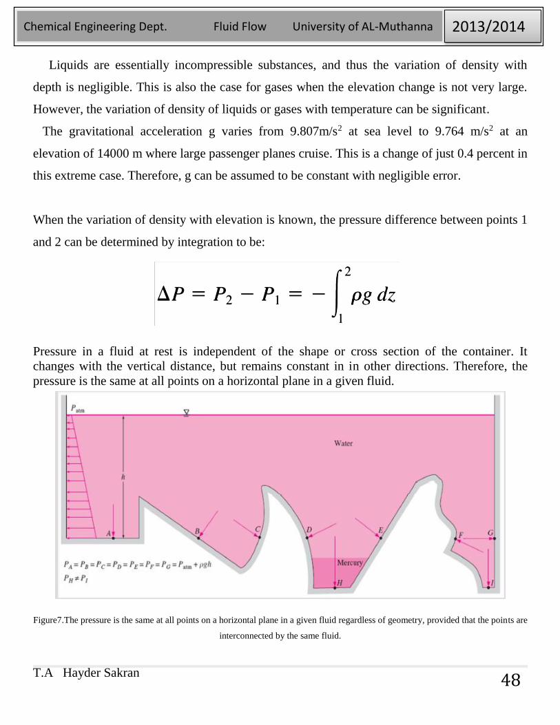
If we take point 1 to be at free surface of a liquid open to atmosphere (Figure6), where the
pressure is the atmospheric pressure Patm, then the pressure at a depth h from the free surface
becomes:
Figure6.Pressure in a liquid at rest increases linearly with distance from the free surface.
T.A Hayder Sakran
Chemical Engineering Dept. Fluid Flow University of AL-Muthanna 2013/2014
48
Liquids are essentially incompressible substances, and thus the variation of density with
depth is negligible. This is also the case for gases when the elevation change is not very large.
However, the variation of density of liquids or gases with temperature can be significant.
The gravitational acceleration g varies from 9.807m/s2 at sea level to 9.764 m/s2 at an
elevation of 14000 m where large passenger planes cruise. This is a change of just 0.4 percent in
this extreme case. Therefore, g can be assumed to be constant with negligible error.
When the variation of density with elevation is known, the pressure difference between points 1
and 2 can be determined by integration to be:
Pressure in a fluid at rest is independent of the shape or cross section of the container. It
changes with the vertical distance, but remains constant in in other directions. Therefore, the
pressure is the same at all points on a horizontal plane in a given fluid.
Figure7.The pressure is the same at all points on a horizontal plane in a given fluid regardless of geometry, provided that the points are
interconnected by the same fluid.
T.A Hayder Sakran
Chemical Engineering Dept. Fluid Flow University of AL-Muthanna 2013/2014
49
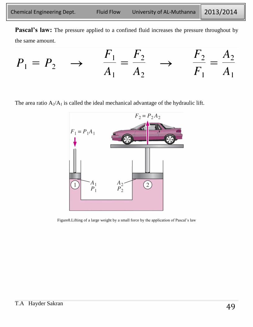
Pascal’s law: The pressure applied to a confined fluid increases the pressure throughout by
the same amount.
The area ratio A2/A1 is called the ideal mechanical advantage of the hydraulic lift.
Figure8.Lifting of a large weight by a small force by the application of Pascal’s law
T.A Hayder Sakran
Chemical Engineering Dept. Fluid Flow University of AL-Muthanna 2013/2014
50
2- PRESSURE MEASUREMENT DEVICES
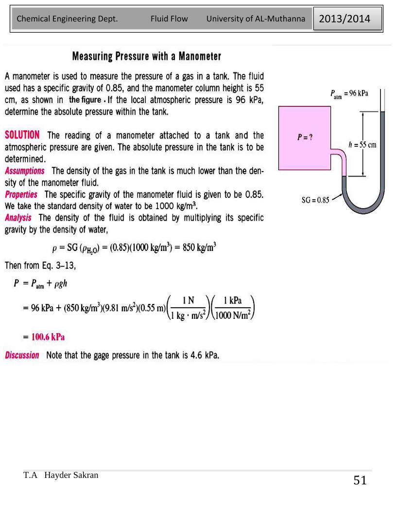
2-1. The Manometer:
It is commonly used to measure small and moderate pressure differences. A
manometer contains one or more fluids such as mercury, water, alcohol, or oil.
Fluid column can be used to measure pressure differences. To keep the size of the
manometer to a manageable level, heavy fluids such as mercury are used if large
pressure differences are anticipated.
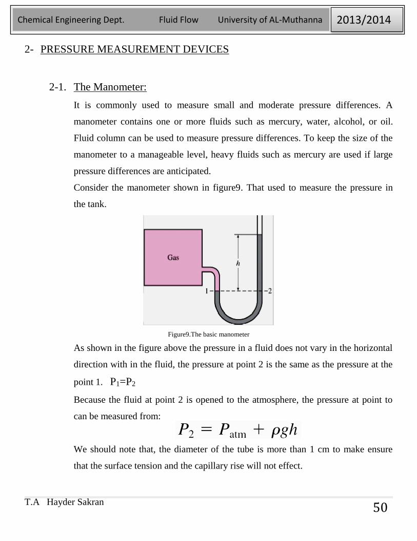
Consider the manometer shown in figure9. That used to measure the pressure in
the tank.
Figure9.The basic manometer
As shown in the figure above the pressure in a fluid does not vary in the horizontal
direction with in the fluid, the pressure at point 2 is the same as the pressure at the
point 1. P1=P2
Because the fluid at point 2 is opened to the atmosphere, the pressure at point to
can be measured from:
We should note that, the diameter of the tube is more than 1 cm to make ensure
that the surface tension and the capillary rise will not effect.
T.A Hayder Sakran
Chemical Engineering Dept. Fluid Flow University of AL-Muthanna 2013/2014
51
T.A Hayder Sakran
Chemical Engineering Dept. Fluid Flow University of AL-Muthanna 2013/2014
52
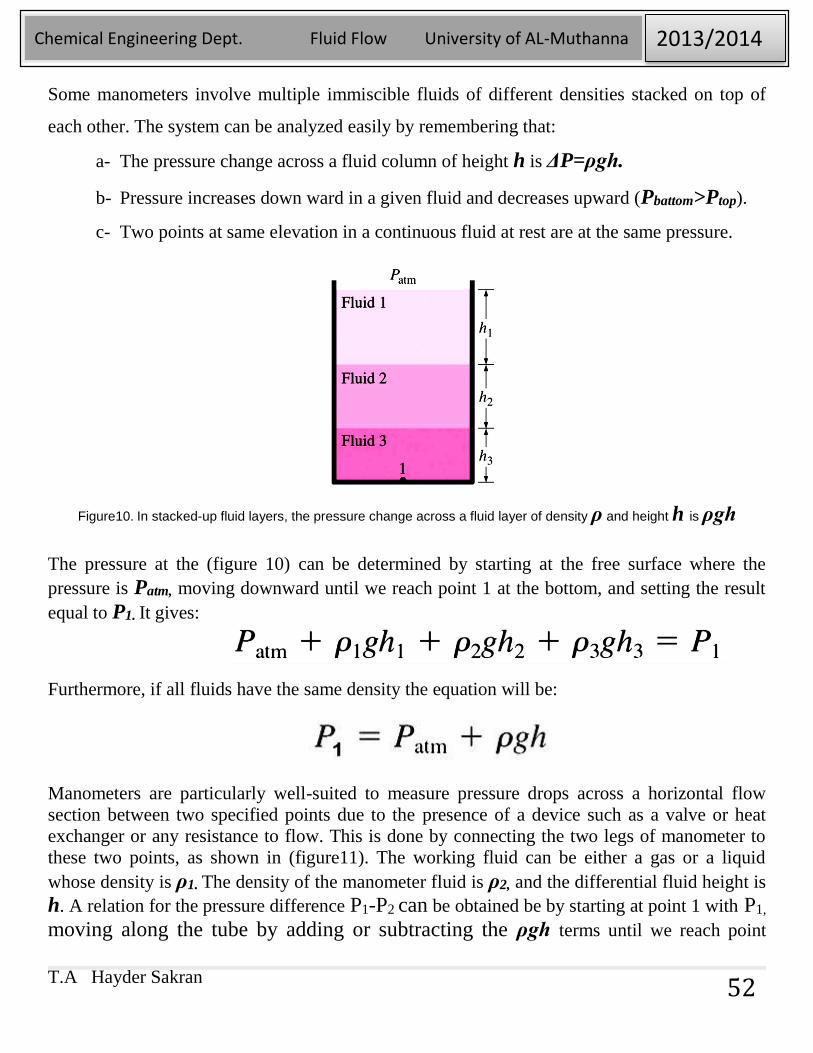
Some manometers involve multiple immiscible fluids of different densities stacked on top of
each other. The system can be analyzed easily by remembering that:
a- The pressure change across a fluid column of height h is ΔP=ρgh.
b- Pressure increases down ward in a given fluid and decreases upward (Pbattom>Ptop).
c- Two points at same elevation in a continuous fluid at rest are at the same pressure.
Figure10. In stacked-up fluid layers, the pressure change across a fluid layer of density ρ and height h is ρgh
The pressure at the (figure 10) can be determined by starting at the free surface where the
pressure is Patm, moving downward until we reach point 1 at the bottom, and setting the result
equal to P1. It gives:
Furthermore, if all fluids have the same density the equation will be:
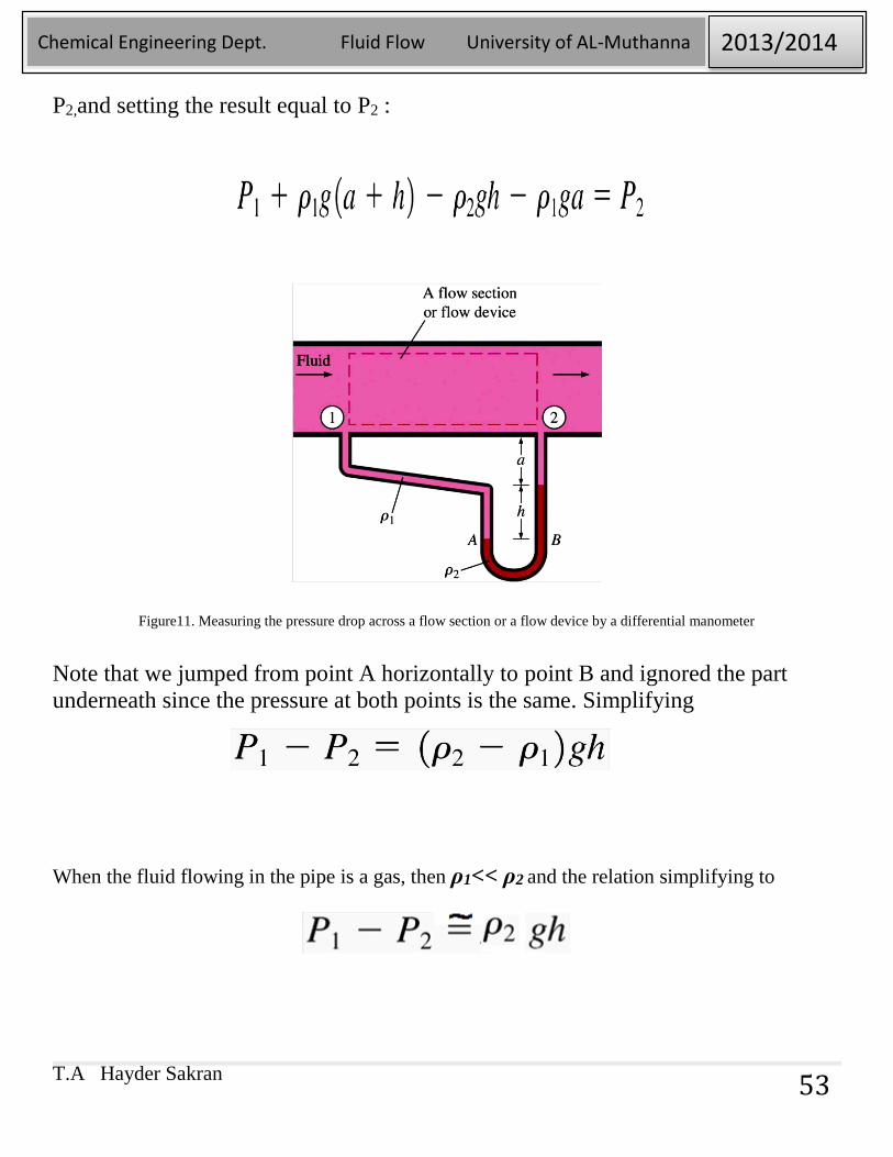
Manometers are particularly well-suited to measure pressure drops across a horizontal flow
section between two specified points due to the presence of a device such as a valve or heat
exchanger or any resistance to flow. This is done by connecting the two legs of manometer to
these two points, as shown in (figure11). The working fluid can be either a gas or a liquid
whose density is ρ1. The density of the manometer fluid is ρ2, and the differential fluid height is
h. A relation for the pressure difference P1-P2 can be obtained be by starting at point 1 with P1,
moving along the tube by adding or subtracting the ρgh terms until we reach point
T.A Hayder Sakran
Chemical Engineering Dept. Fluid Flow University of AL-Muthanna 2013/2014
53
P2,and setting the result equal to P2 :
Figure11. Measuring the pressure drop across a flow section or a flow device by a differential manometer
Note that we jumped from point A horizontally to point B and ignored the part
underneath since the pressure at both points is the same. Simplifying
When the fluid flowing in the pipe is a gas, then ρ1<< ρ2 and the relation simplifying to
T.A Hayder Sakran
Chemical Engineering Dept. Fluid Flow University of AL-Muthanna 2013/2014
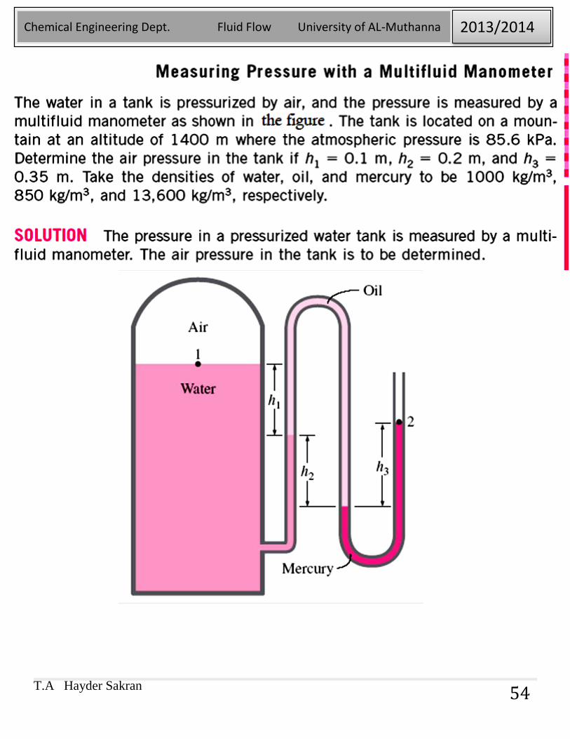
54
T.A Hayder Sakran
Chemical Engineering Dept. Fluid Flow University of AL-Muthanna 2013/2014
55
T.A Hayder Sakran
Chemical Engineering Dept. Fluid Flow University of AL-Muthanna 2013/2014
56
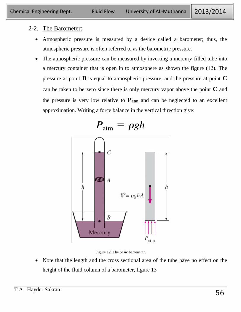
2-2. The Barometer:
Atmospheric pressure is measured by a device called a barometer; thus, the
atmospheric pressure is often referred to as the barometric pressure.
The atmospheric pressure can be measured by inverting a mercury-filled tube into
a mercury container that is open in to atmosphere as shown the figure (12). The
pressure at point B is equal to atmospheric pressure, and the pressure at point C
can be taken to be zero since there is only mercury vapor above the point C and
the pressure is very low relative to Patm and can be neglected to an excellent
approximation. Writing a force balance in the vertical direction give:
Figure 12. The basic barometer.
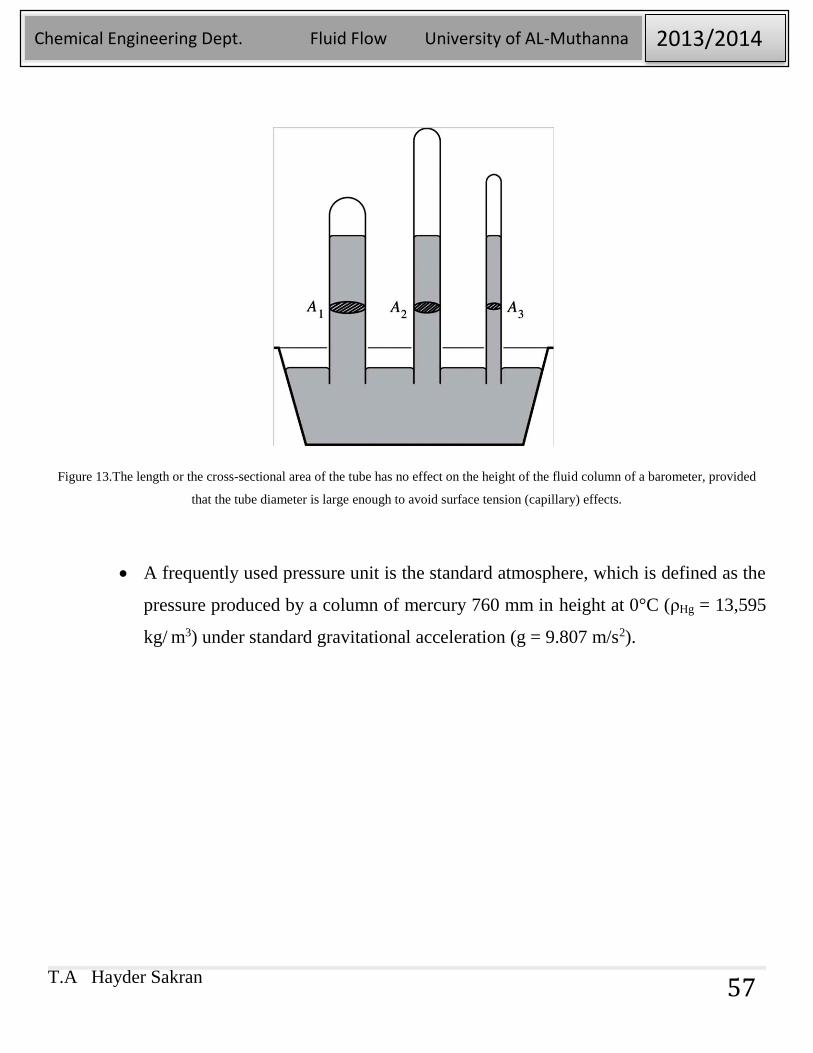
Note that the length and the cross sectional area of the tube have no effect on the
height of the fluid column of a barometer, figure 13
T.A Hayder Sakran
Chemical Engineering Dept. Fluid Flow University of AL-Muthanna 2013/2014
57
Figure 13.The length or the cross-sectional area of the tube has no effect on the height of the fluid column of a barometer, provided
that the tube diameter is large enough to avoid surface tension (capillary) effects.
A frequently used pressure unit is the standard atmosphere, which is defined as the
pressure produced by a column of mercury 760 mm in height at 0°C (ρHg = 13,595
kg/ m3) under standard gravitational acceleration (g = 9.807 m/s2).
T.A Hayder Sakran
Chemical Engineering Dept. Fluid Flow University of AL-Muthanna 2013/2014
58
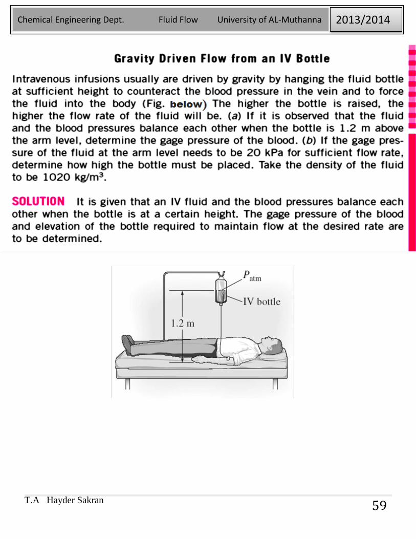
T.A Hayder Sakran
Chemical Engineering Dept. Fluid Flow University of AL-Muthanna 2013/2014
59
T.A Hayder Sakran
Chemical Engineering Dept. Fluid Flow University of AL-Muthanna 2013/2014
60
T.A Hayder Sakran
Chemical Engineering Dept. Fluid Flow University of AL-Muthanna 2013/2014
61
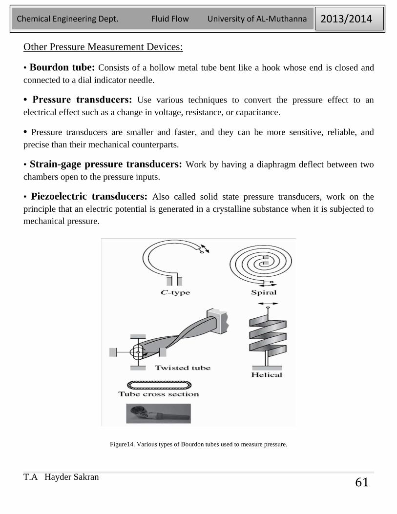
Other Pressure Measurement Devices:
• Bourdon tube: Consists of a hollow metal tube bent like a hook whose end is closed and
connected to a dial indicator needle.
• Pressure transducers: Use various techniques to convert the pressure effect to an
electrical effect such as a change in voltage, resistance, or capacitance.
• Pressure transducers are smaller and faster, and they can be more sensitive, reliable, and
precise than their mechanical counterparts.
• Strain-gage pressure transducers: Work by having a diaphragm deflect between two
chambers open to the pressure inputs.
• Piezoelectric transducers: Also called solid state pressure transducers, work on the
principle that an electric potential is generated in a crystalline substance when it is subjected to
mechanical pressure.
Figure14. Various types of Bourdon tubes used to measure pressure.
T.A Hayder Sakran
Chemical Engineering Dept. Fluid Flow University of AL-Muthanna 2013/2014
62
3- BUOYANCY:
Buoyant force: The upward force a fluid exerts on a body immersed in it. The buoyant
force is caused by the increase of pressure with depth in a fluid.
The buoyant force acting on the plate is equal to the weight of the liquid displaced by the
plate. For a fluid with constant density, the buoyant force is independent of the distance of
the body from the free surface. It is also independent of the density of the solid body.
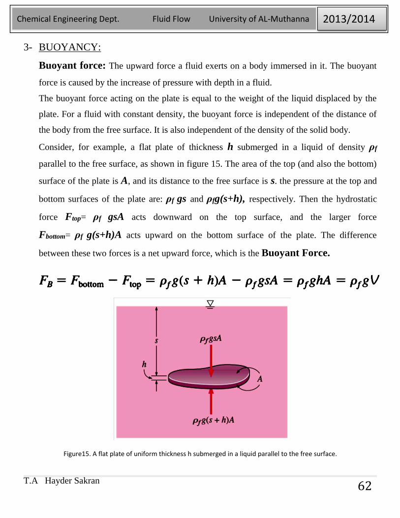
Consider, for example, a flat plate of thickness h submerged in a liquid of density ρf
parallel to the free surface, as shown in figure 15. The area of the top (and also the bottom)
surface of the plate is A, and its distance to the free surface is s. the pressure at the top and
bottom surfaces of the plate are: ρf gs and ρfg(s+h), respectively. Then the hydrostatic
force Ftop= ρf gsA acts downward on the top surface, and the larger force
Fbottom= ρf g(s+h)A acts upward on the bottom surface of the plate. The difference
between these two forces is a net upward force, which is the Buoyant Force.
Figure15. A flat plate of uniform thickness h submerged in a liquid parallel to the free surface.
T.A Hayder Sakran
Chemical Engineering Dept. Fluid Flow University of AL-Muthanna 2013/2014
63
Where V=hA is the volume of the plate. But the relation ρf gV is simply the weight of the
liquid whose volume is equal to the volume of the plate.
Buoyant force acting on the plate is equal to the weight of the liquid displaced by the plate.
Note that: the buoyant force is independent of the distance of the body from the free surface. It
is also independent of the density of the solid body.
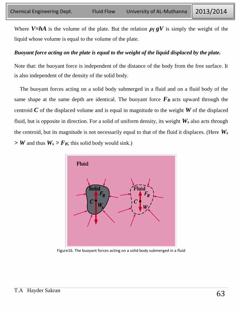
The buoyant forces acting on a solid body submerged in a fluid and on a fluid body of the
same shape at the same depth are identical. The buoyant force FB acts upward through the
centroid C of the displaced volume and is equal in magnitude to the weight W of the displaced
fluid, but is opposite in direction. For a solid of uniform density, its weight Ws also acts through
the centroid, but its magnitude is not necessarily equal to that of the fluid it displaces. (Here Ws
> W and thus Ws > FB; this solid body would sink.)
Figure16. The buoyant forces acting on a solid body submerged in a fluid
T.A Hayder Sakran
Chemical Engineering Dept. Fluid Flow University of AL-Muthanna 2013/2014
64
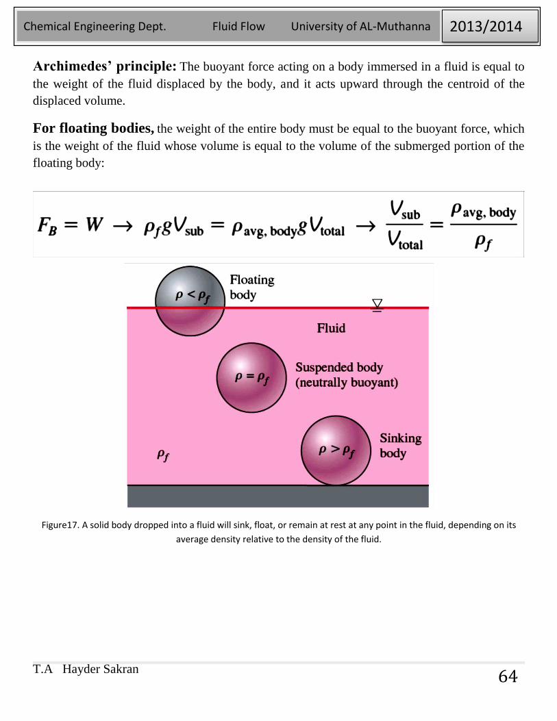
Archimedes’ principle: The buoyant force acting on a body immersed in a fluid is equal to
the weight of the fluid displaced by the body, and it acts upward through the centroid of the
displaced volume.
For floating bodies, the weight of the entire body must be equal to the buoyant force, which
is the weight of the fluid whose volume is equal to the volume of the submerged portion of the
floating body:
Figure17. A solid body dropped into a fluid will sink, float, or remain at rest at any point in the fluid, depending on its
average density relative to the density of the fluid.
T.A Hayder Sakran
Chemical Engineering Dept. Fluid Flow University of AL-Muthanna 2013/2014
65
The body immerged in fluid is:
1- Remains at rest at any point in the fluid when its density is equal to the density of the
fluid.
2- Sinks to the bottom when its density is greater than the density of the fluid.
3- Rises to the surface of the fluid and float when the density of the body is less than the
density of the fluid.
As shown in the figure17.
Buoyant force is proportional to the density of the fluid, and thus we might think that the
buoyant force exerted by gases such as air is negligible.
However, buoyant forces in gases dominate some important natural phenomena such as the rise
of worm air in a cooler environment.
T.A Hayder Sakran
Chemical Engineering Dept. Fluid Flow University of AL-Muthanna 2013/2014
66
T.A Hayder Sakran
Chemical Engineering Dept. Fluid Flow University of AL-Muthanna 2013/2014
67
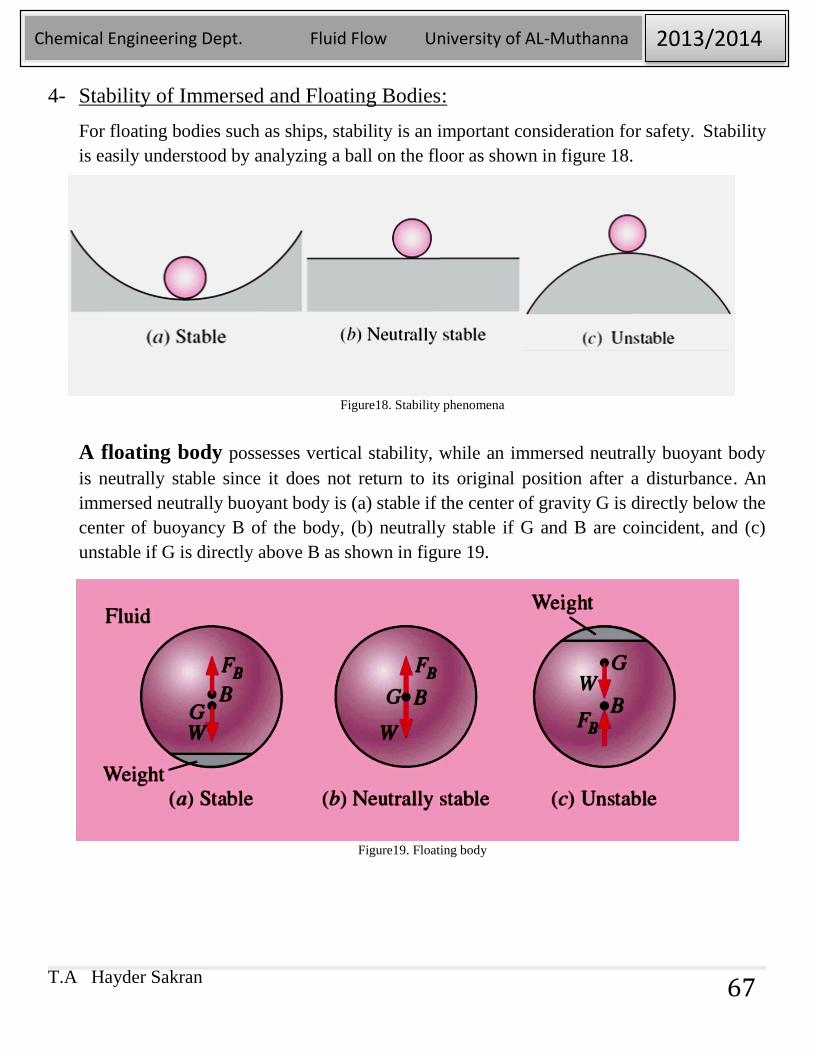
4- Stability of Immersed and Floating Bodies:
For floating bodies such as ships, stability is an important consideration for safety. Stability
is easily understood by analyzing a ball on the floor as shown in figure 18.
Figure18. Stability phenomena
A floating body possesses vertical stability, while an immersed neutrally buoyant body
is neutrally stable since it does not return to its original position after a disturbance. An
immersed neutrally buoyant body is (a) stable if the center of gravity G is directly below the
center of buoyancy B of the body, (b) neutrally stable if G and B are coincident, and (c)
unstable if G is directly above B as shown in figure 19.
Figure19. Floating body
T.A Hayder Sakran
Chemical Engineering Dept. Fluid Flow University of AL-Muthanna 2013/2014
68
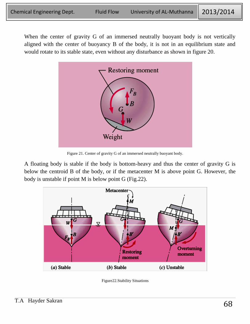
When the center of gravity G of an immersed neutrally buoyant body is not vertically
aligned with the center of buoyancy B of the body, it is not in an equilibrium state and
would rotate to its stable state, even without any disturbance as shown in figure 20.
Figure 21. Center of gravity G of an immersed neutrally buoyant body.
A floating body is stable if the body is bottom-heavy and thus the center of gravity G is
below the centroid B of the body, or if the metacenter M is above point G. However, the
body is unstable if point M is below point G (Fig.22).
Figure22.Stability Situations
T.A Hayder Sakran
Chemical Engineering Dept. Fluid Flow University of AL-Muthanna 2013/2014
69
Metacentric height GM: The distance between the center of gravity G and the
metacenter M—the intersection point of the lines of action of the buoyant force through the
body before and after rotation. The length of the metacentric height GM above G is a
measure of the stability: the larger it is, the more stable is the floating body.
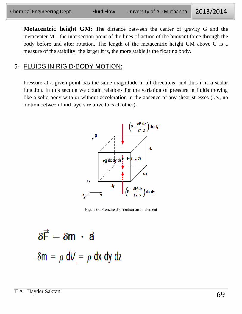
5- FLUIDS IN RIGID-BODY MOTION:
Pressure at a given point has the same magnitude in all directions, and thus it is a scalar
function. In this section we obtain relations for the variation of pressure in fluids moving
like a solid body with or without acceleration in the absence of any shear stresses (i.e., no
motion between fluid layers relative to each other).
Figure23. Pressure distribution on an element
T.A Hayder Sakran
Chemical Engineering Dept. Fluid Flow University of AL-Muthanna 2013/2014
70
T.A Hayder Sakran
Chemical Engineering Dept. Fluid Flow University of AL-Muthanna 2013/2014
71
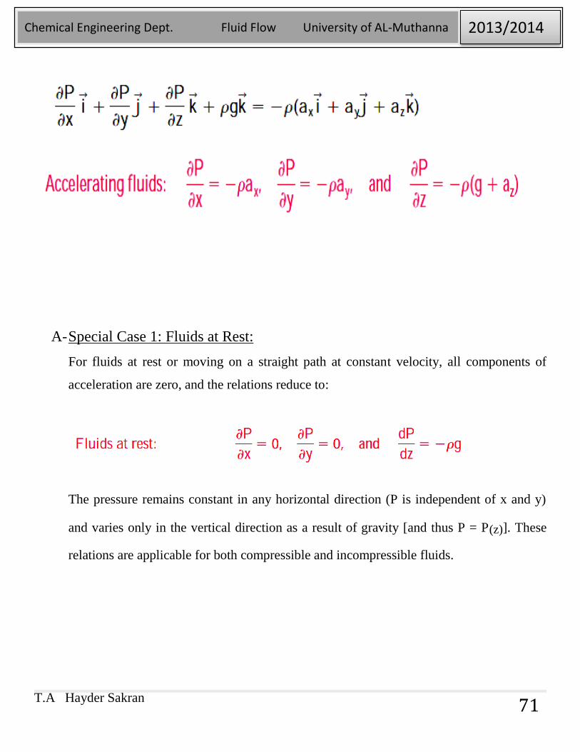
A- Special Case 1: Fluids at Rest:
For fluids at rest or moving on a straight path at constant velocity, all components of
acceleration are zero, and the relations reduce to:
The pressure remains constant in any horizontal direction (P is independent of x and y)
and varies only in the vertical direction as a result of gravity [and thus P = P(z)]. These
relations are applicable for both compressible and incompressible fluids.
T.A Hayder Sakran
Chemical Engineering Dept. Fluid Flow University of AL-Muthanna 2013/2014
72
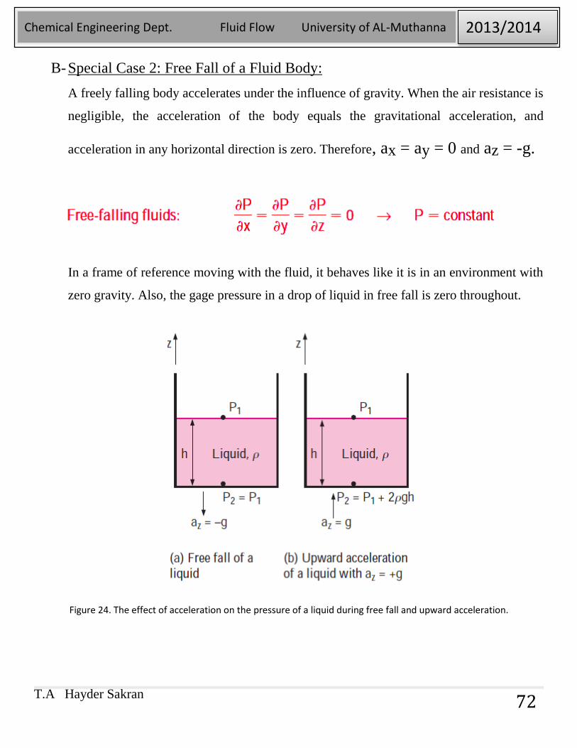
B- Special Case 2: Free Fall of a Fluid Body:
A freely falling body accelerates under the influence of gravity. When the air resistance is
negligible, the acceleration of the body equals the gravitational acceleration, and
acceleration in any horizontal direction is zero. Therefore, ax = ay = 0 and az = -g.
In a frame of reference moving with the fluid, it behaves like it is in an environment with
zero gravity. Also, the gage pressure in a drop of liquid in free fall is zero throughout.
Figure 24. The effect of acceleration on the pressure of a liquid during free fall and upward acceleration.
T.A Hayder Sakran
Chemical Engineering Dept. Fluid Flow University of AL-Muthanna 2013/2014
73
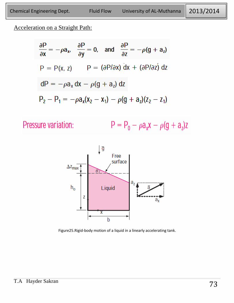
Acceleration on a Straight Path:
Figure25.Rigid-body motion of a liquid in a linearly accelerating tank.
T.A Hayder Sakran
Chemical Engineering Dept. Fluid Flow University of AL-Muthanna 2013/2014
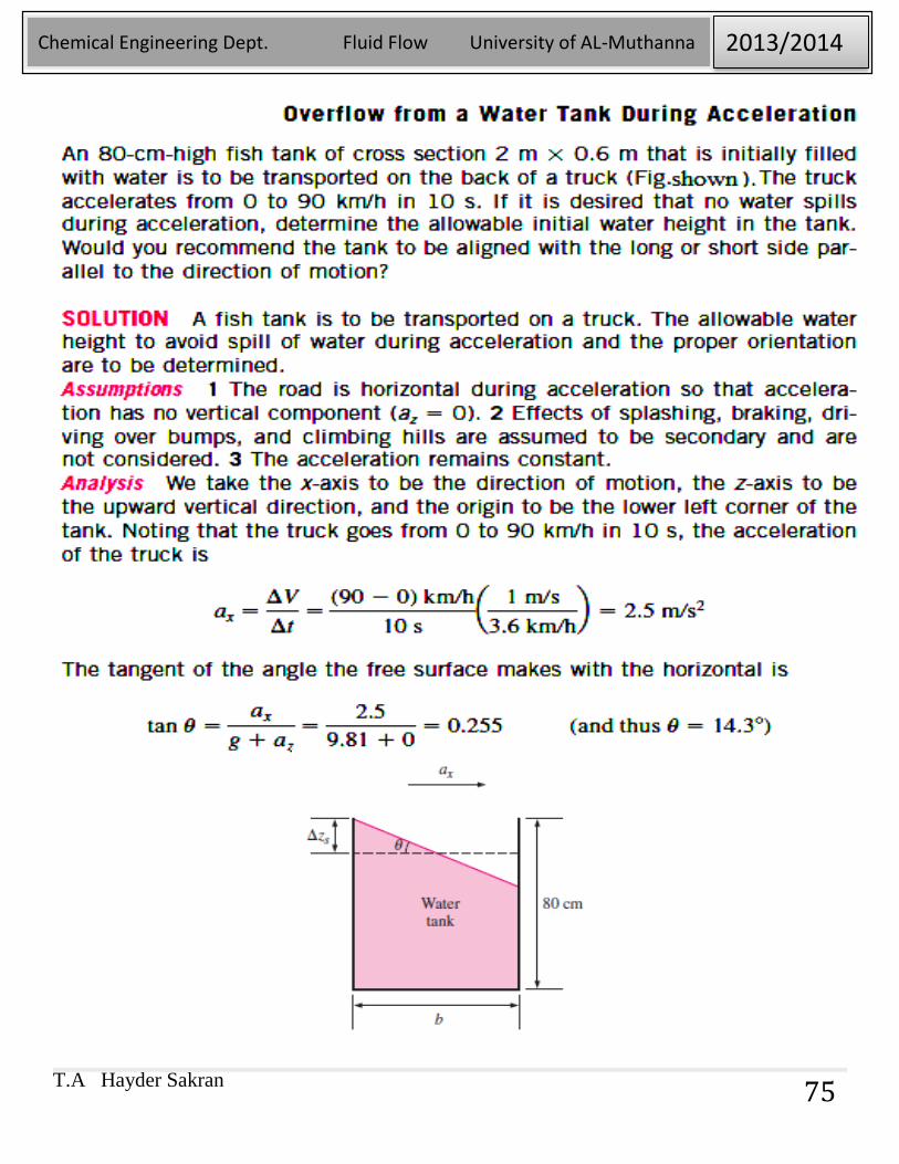
74
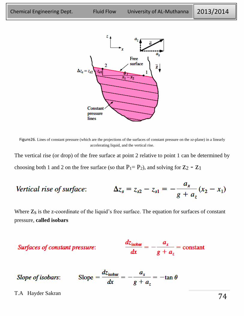
Figure26. Lines of constant pressure (which are the projections of the surfaces of constant pressure on the xz-plane) in a linearly
accelerating liquid, and the vertical rise.
The vertical rise (or drop) of the free surface at point 2 relative to point 1 can be determined by
choosing both 1 and 2 on the free surface (so that P1= P2), and solving for z2 - z1
Where zs is the z-coordinate of the liquid’s free surface. The equation for surfaces of constant
pressure, called isobars
T.A Hayder Sakran
Chemical Engineering Dept. Fluid Flow University of AL-Muthanna 2013/2014
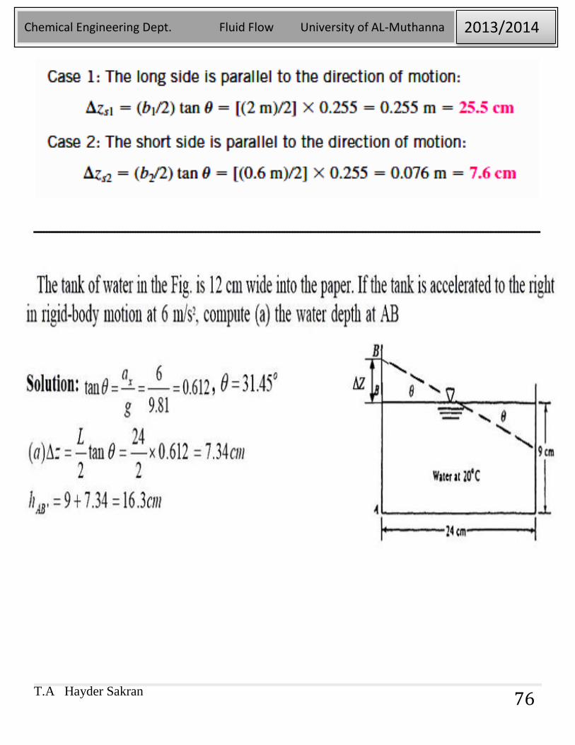
75
T.A Hayder Sakran
Chemical Engineering Dept. Fluid Flow University of AL-Muthanna 2013/2014
76
ــــــــــــــــــــــــــــــــــــــــــــــــــــــــــــــــــــــــــــــــــــــــــــــــــــــــــــــــــــــــــــــــــــــــــــــــــــــــــــــــــــــــــــــــــــــــــــــــــ
T.A Hayder Sakran
Chemical Engineering Dept. Fluid Flow University of AL-Muthanna 2013/2014
77
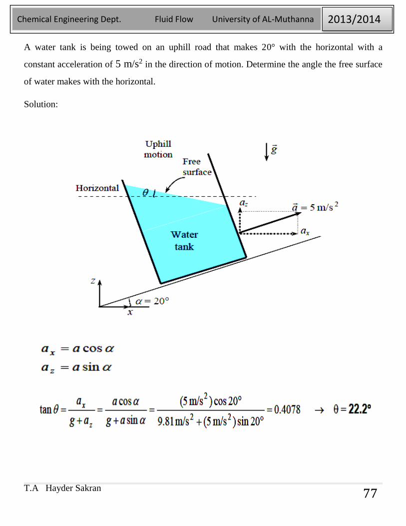
A water tank is being towed on an uphill road that makes 20° with the horizontal with a
constant acceleration of 5 m/s2 in the direction of motion. Determine the angle the free surface
of water makes with the horizontal.
Solution:
T.A Hayder Sakran
Chemical Engineering Dept. Fluid Flow University of AL-Muthanna 2013/2014
78
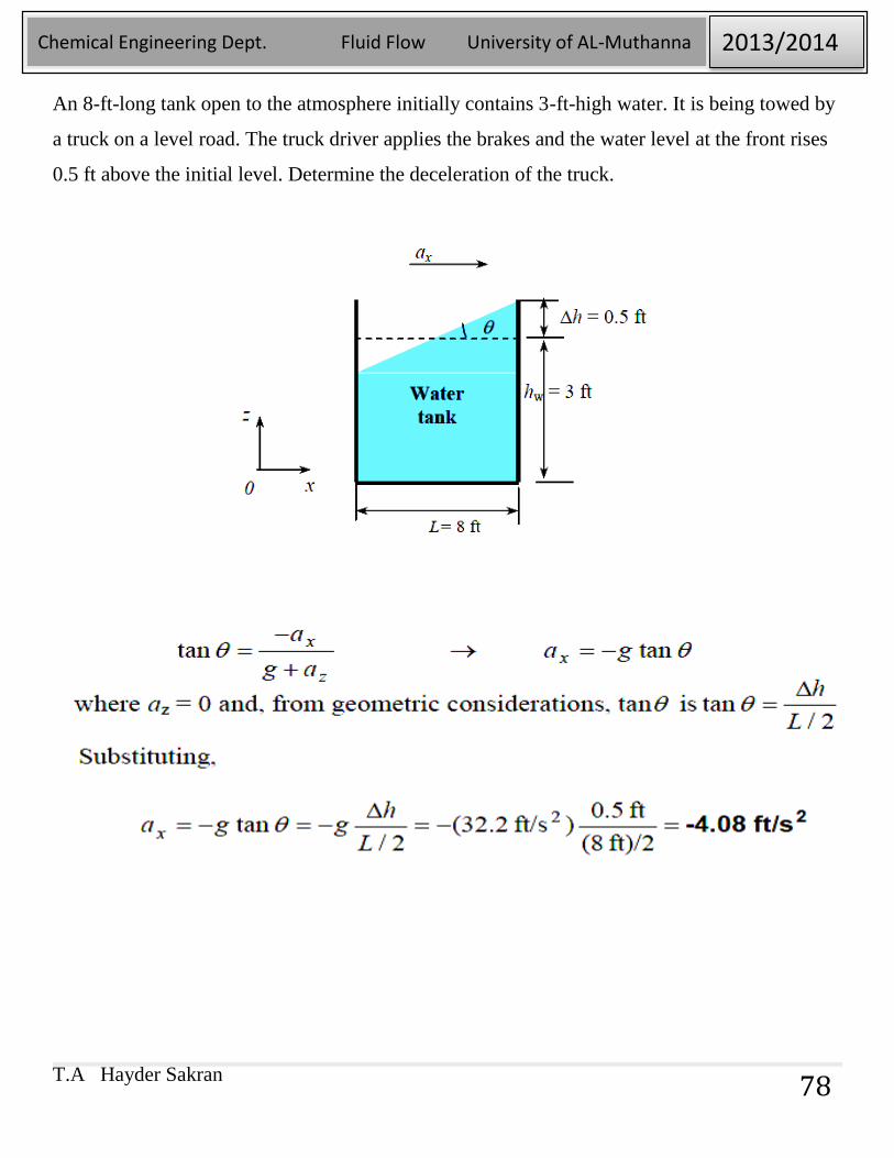
An 8-ft-long tank open to the atmosphere initially contains 3-ft-high water. It is being towed by
a truck on a level road. The truck driver applies the brakes and the water level at the front rises
0.5 ft above the initial level. Determine the deceleration of the truck.
T.A Hayder Sakran
Chemical Engineering Dept. Fluid Flow University of AL-Muthanna 2013/2014
79
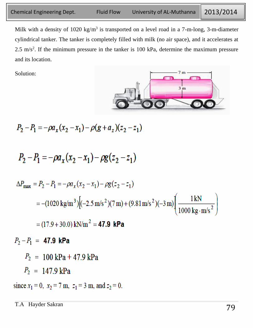
Milk with a density of 1020 kg/m3 is transported on a level road in a 7-m-long, 3-m-diameter
cylindrical tanker. The tanker is completely filled with milk (no air space), and it accelerates at
2.5 m/s2. If the minimum pressure in the tanker is 100 kPa, determine the maximum pressure
and its location.
Solution:
T.A Hayder Sakran
Chemical Engineering Dept. Fluid Flow University of AL-Muthanna 2013/2014
80
Chapter 4
FLUID KINEMATICS
T.A Hayder Sakran
Chemical Engineering Dept. Fluid Flow University of AL-Muthanna 2013/2014
81
4-1. LAGRANGIAN AND EULERIAN DESCRIPTIONS:
Fluid kinematics deals with describing the motion of fluids without necessarily considering
the forces and moments that cause the motion. The subject called kinematics concerns the study
of motion. In fluid dynamics, fluid kinematics is the study of how fluids flow and how to
describe fluid motion. There are two distinct ways to describe motion which are Lagrangian
and Eulerian.
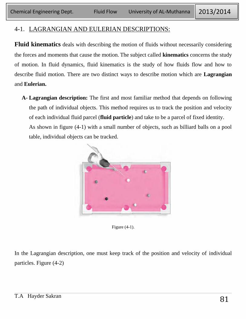
A- Lagrangian description: The first and most familiar method that depends on following
the path of individual objects. This method requires us to track the position and velocity
of each individual fluid parcel (fluid particle) and take to be a parcel of fixed identity.
As shown in figure (4-1) with a small number of objects, such as billiard balls on a pool
table, individual objects can be tracked.
Figure (4-1).
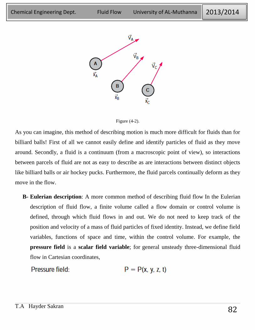
In the Lagrangian description, one must keep track of the position and velocity of individual
particles. Figure (4-2)
T.A Hayder Sakran
Chemical Engineering Dept. Fluid Flow University of AL-Muthanna 2013/2014
82
Figure (4-2).
As you can imagine, this method of describing motion is much more difficult for fluids than for
billiard balls! First of all we cannot easily define and identify particles of fluid as they move
around. Secondly, a fluid is a continuum (from a macroscopic point of view), so interactions
between parcels of fluid are not as easy to describe as are interactions between distinct objects
like billiard balls or air hockey pucks. Furthermore, the fluid parcels continually deform as they
move in the flow.
B- Eulerian description: A more common method of describing fluid flow In the Eulerian
description of fluid flow, a finite volume called a flow domain or control volume is
defined, through which fluid flows in and out. We do not need to keep track of the
position and velocity of a mass of fluid particles of fixed identity. Instead, we define field
variables, functions of space and time, within the control volume. For example, the
pressure field is a scalar field variable; for general unsteady three-dimensional fluid
flow in Cartesian coordinates,
T.A Hayder Sakran
Chemical Engineering Dept. Fluid Flow University of AL-Muthanna 2013/2014
83
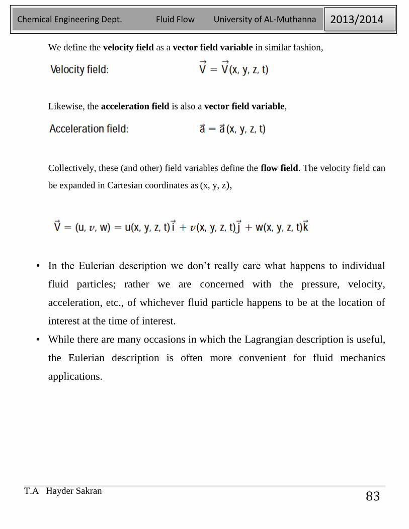
We define the velocity field as a vector field variable in similar fashion,
Likewise, the acceleration field is also a vector field variable,
Collectively, these (and other) field variables define the flow field. The velocity field can
be expanded in Cartesian coordinates as (x, y, z),
• In the Eulerian description we don’t really care what happens to individual
fluid particles; rather we are concerned with the pressure, velocity,
acceleration, etc., of whichever fluid particle happens to be at the location of
interest at the time of interest.
• While there are many occasions in which the Lagrangian description is useful,
the Eulerian description is often more convenient for fluid mechanics
applications.
T.A Hayder Sakran
Chemical Engineering Dept. Fluid Flow University of AL-Muthanna 2013/2014
84
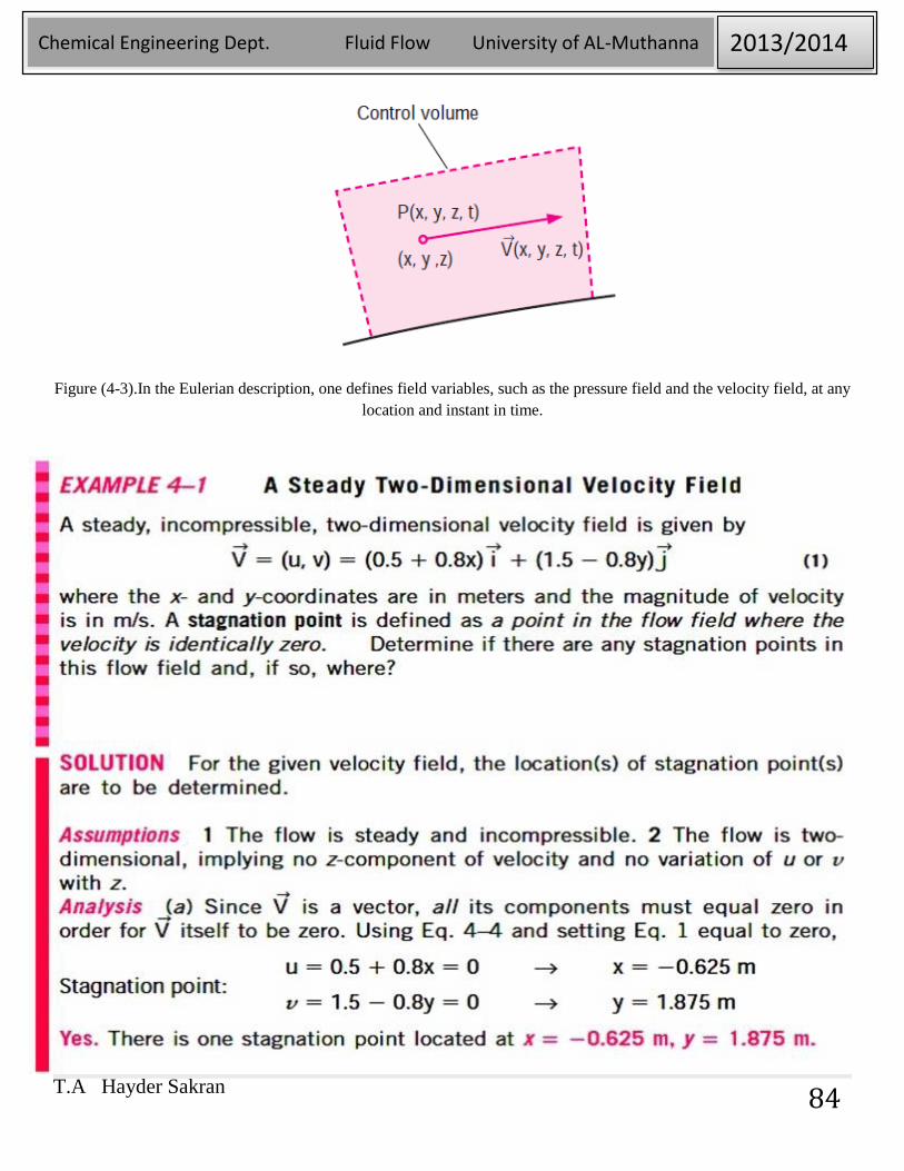
Figure (4-3).In the Eulerian description, one defines field variables, such as the pressure field and the velocity field, at any
location and instant in time.
T.A Hayder Sakran
Chemical Engineering Dept. Fluid Flow University of AL-Muthanna 2013/2014
85
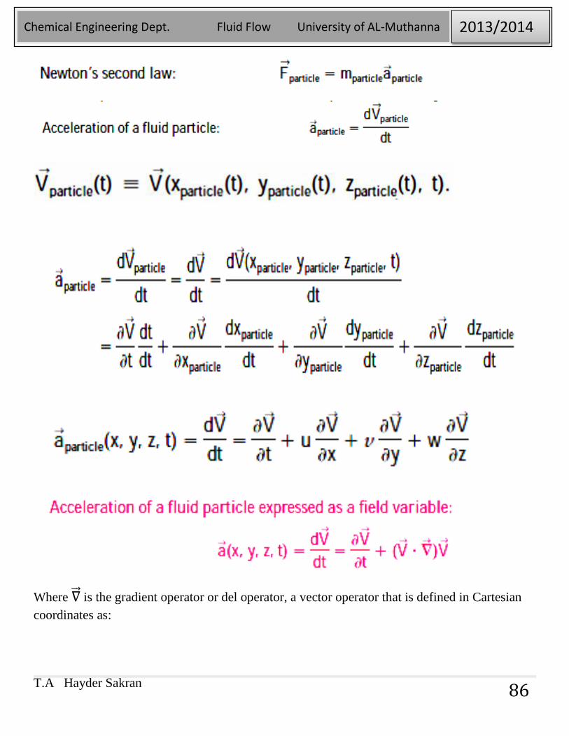
4-2. Acceleration Field:
The equations of motion for fluid flow (such as Newton’s second law) are written for a
fluid particle, which we also call a material particle. If we were to follow a particular fluid
particle as it moves around in the flow, we would be employing the Lagrangian description,
and the equations of motion would be directly applicable. For example, we would define
the particle’s location in space in terms of a material position vector (xparticle (t),
yparticle (t), zparticle (t)).
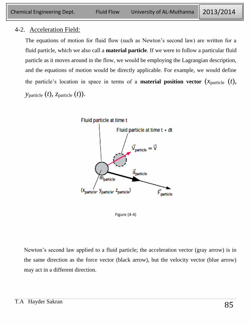
Figure (4-4)
Newton’s second law applied to a fluid particle; the acceleration vector (gray arrow) is in
the same direction as the force vector (black arrow), but the velocity vector (blue arrow)
may act in a different direction.
T.A Hayder Sakran
Chemical Engineering Dept. Fluid Flow University of AL-Muthanna 2013/2014
86
Where ∇⃗⃗ is the gradient operator or del operator, a vector operator that is defined in Cartesian
coordinates as:
T.A Hayder Sakran
Chemical Engineering Dept. Fluid Flow University of AL-Muthanna 2013/2014
87
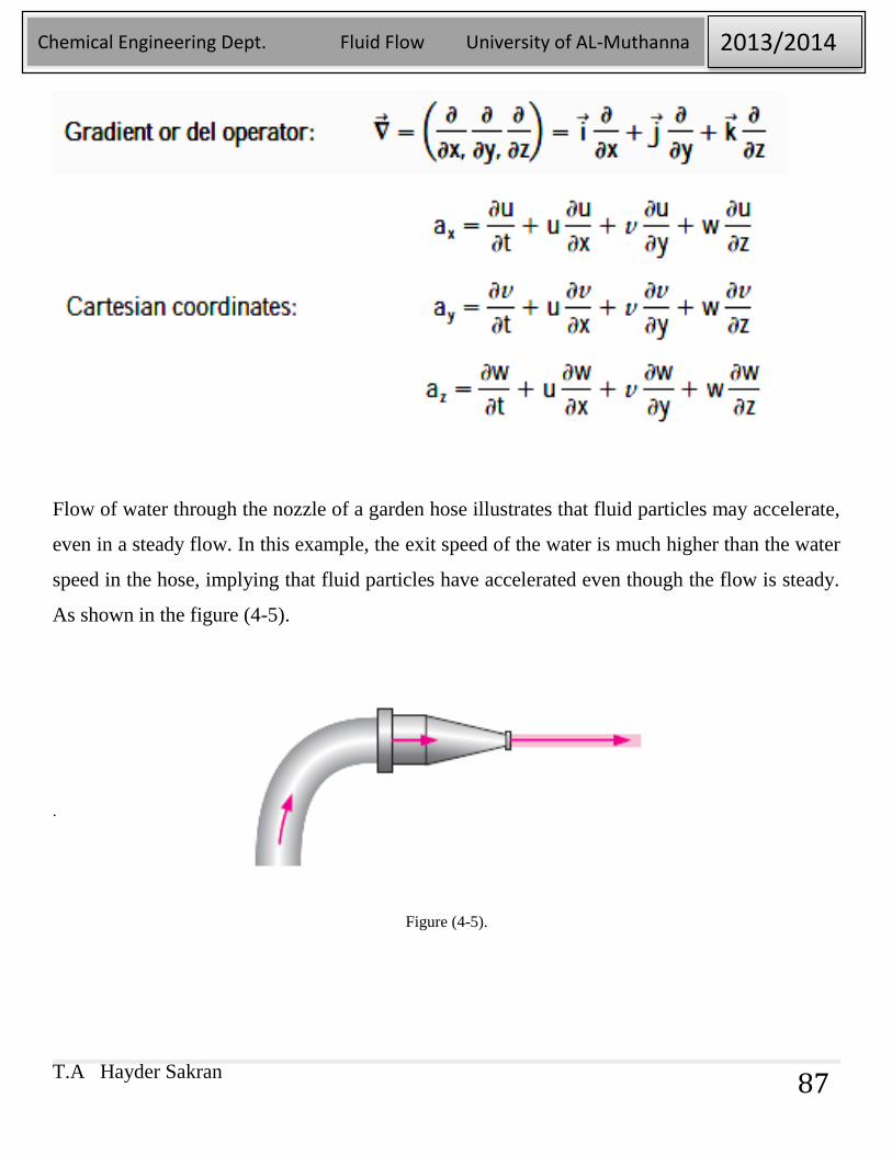
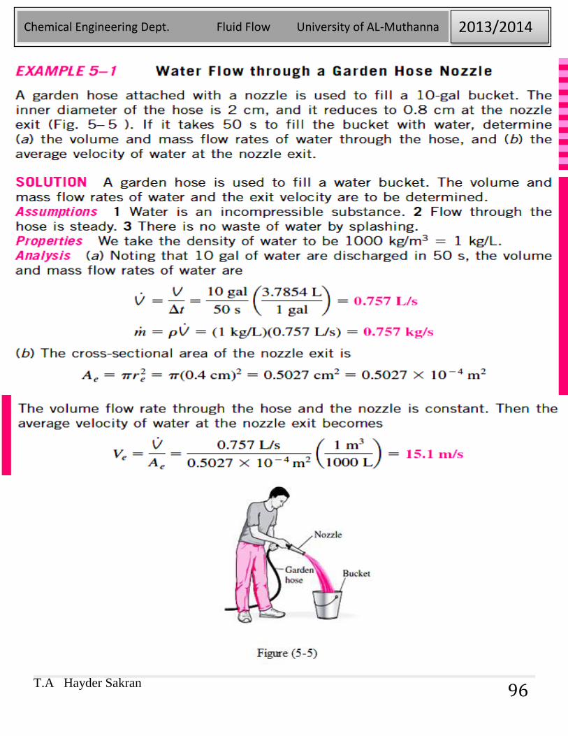
Flow of water through the nozzle of a garden hose illustrates that fluid particles may accelerate,
even in a steady flow. In this example, the exit speed of the water is much higher than the water
speed in the hose, implying that fluid particles have accelerated even though the flow is steady.
As shown in the figure (4-5).
.
Figure (4-5).
T.A Hayder Sakran
Chemical Engineering Dept. Fluid Flow University of AL-Muthanna 2013/2014
88
T.A Hayder Sakran
Chemical Engineering Dept. Fluid Flow University of AL-Muthanna 2013/2014
89
Chapter5
MASS, BERNOULLI, AND ENERGY EQUATIONS
5-1. Introduction:
This chapter deals with three equations commonly used in fluid mechanics: the mass,
Bernoulli, and energy equations. The mass equation is an expression of the conservation
of mass principle. The Bernoulli equation is concerned with the conservation of kinetic,
potential, and flow energies of a fluid stream and their conversion to each other in regions
of flow where net viscous forces are negligible and where other restrictive conditions
apply.
Historically, the conservation laws are first applied to a fixed quantity of matter called a
closed system or just a system, and then extended to regions in space called control
volumes. The conservation relations are also called balance equations since any
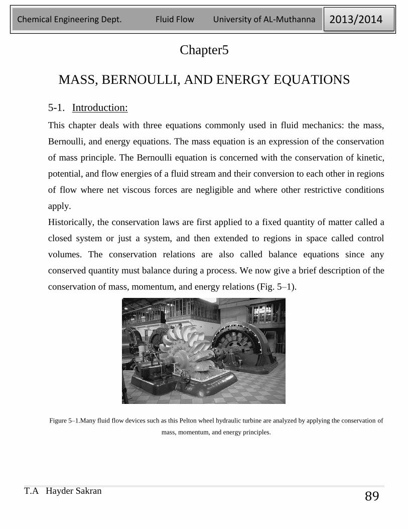
conserved quantity must balance during a process. We now give a brief description of the
conservation of mass, momentum, and energy relations (Fig. 5–1).
Figure 5–1.Many fluid flow devices such as this Pelton wheel hydraulic turbine are analyzed by applying the conservation of
mass, momentum, and energy principles.
T.A Hayder Sakran
Chemical Engineering Dept. Fluid Flow University of AL-Muthanna 2013/2014
90
5-2. Conservation of Mass:
The conservation of mass relation for a closed system undergoing a change is expressed
as msys = constant or dmsys/dt = 0, which is a statement of the obvious that the mass of the
system remains constant during a process. For a control volume (CV), mass balance is
expressed in the rate form as:
Conservation of mass:
Where 𝑚.𝑖𝑛 and 𝑚.
𝑜𝑢𝑡 are the total rates of mass flow into and out of the control
volume, respectively, and dmCV/dt is the rate of change of mass within the control volume
boundaries. In fluid mechanics, the conservation of mass relation written for a differential
control volume is usually called the continuity equation.
Conservation of mass: Mass, like energy, is a conserved property, and it cannot be
created or destroyed during a process.
Closed systems, Control mass: The mass of the system remain constant during a
process.
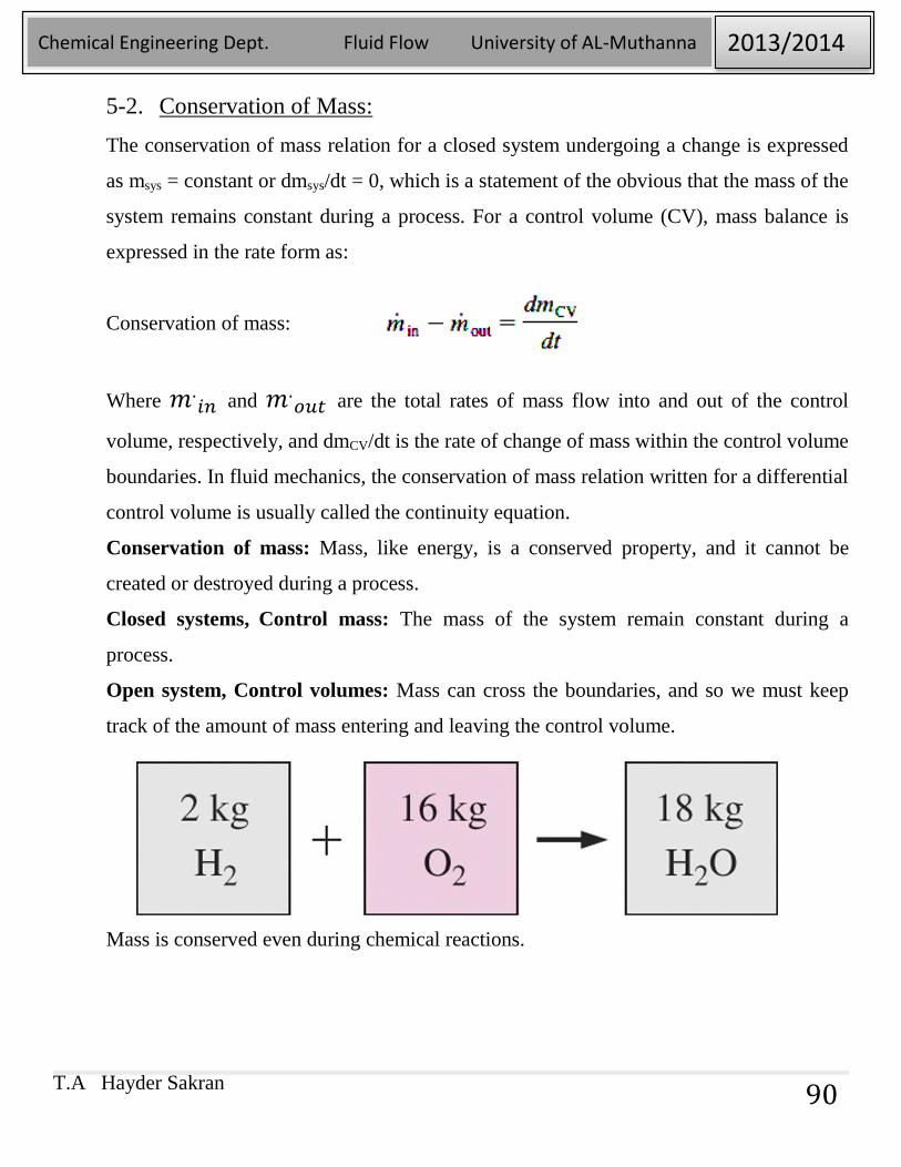
Open system, Control volumes: Mass can cross the boundaries, and so we must keep
track of the amount of mass entering and leaving the control volume.
Mass is conserved even during chemical reactions.
T.A Hayder Sakran
Chemical Engineering Dept. Fluid Flow University of AL-Muthanna 2013/2014
91
5-3. Mass and Volume Flow Rates:
The amount of mass flowing through a cross section per unit time is called the
mass flow rate and is denoted by m∙ .The dot over a symbol is used to indicate
time rate of change.
The volume of the fluid flowing through a cross section per unit time is called the
volume flow rate V∙
The mass and volume flow rates are related by:
.
T.A Hayder Sakran
Chemical Engineering Dept. Fluid Flow University of AL-Muthanna 2013/2014
92
5-4. Conservation of Mass Principle:
The conservation of mass principle for a control volume can be expressed as: The
net mass transfer to or from a control volume during a time interval Δt
is equal to the net change (increase or decrease) in the total mass within
the control volume during Δt. That is,
Where ΔmCV = mfinal – minitial is the change in the mass of the control volume
during the process (Fig. 5–2). It can also be expressed in rate form as
Where 𝑚.𝑖𝑛 and 𝑚.
𝑜𝑢𝑡 are the total rates of mass flow into and out of the
control volume, and dmCV/dt is the rate of change of mass within the control
volume boundaries.
T.A Hayder Sakran
Chemical Engineering Dept. Fluid Flow University of AL-Muthanna 2013/2014
93
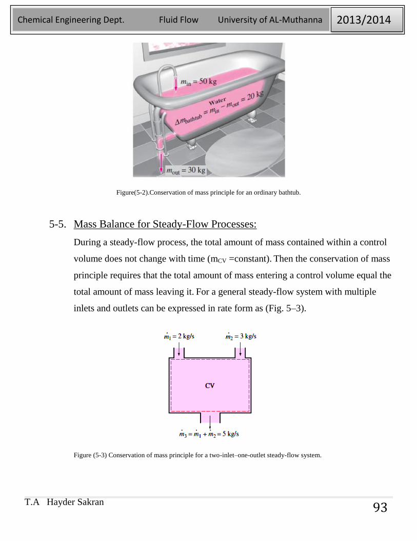
Figure(5-2).Conservation of mass principle for an ordinary bathtub.
5-5. Mass Balance for Steady-Flow Processes:
During a steady-flow process, the total amount of mass contained within a control
volume does not change with time (mCV =constant). Then the conservation of mass
principle requires that the total amount of mass entering a control volume equal the
total amount of mass leaving it. For a general steady-flow system with multiple
inlets and outlets can be expressed in rate form as (Fig. 5–3).
Figure (5-3) Conservation of mass principle for a two-inlet–one-outlet steady-flow system.
T.A Hayder Sakran
Chemical Engineering Dept. Fluid Flow University of AL-Muthanna 2013/2014
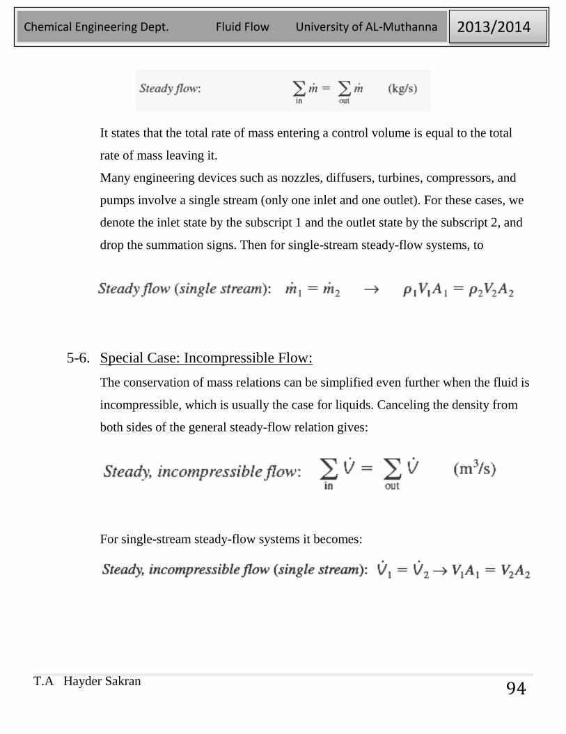
94
It states that the total rate of mass entering a control volume is equal to the total
rate of mass leaving it.
Many engineering devices such as nozzles, diffusers, turbines, compressors, and
pumps involve a single stream (only one inlet and one outlet). For these cases, we
denote the inlet state by the subscript 1 and the outlet state by the subscript 2, and
drop the summation signs. Then for single-stream steady-flow systems, to
5-6. Special Case: Incompressible Flow:
The conservation of mass relations can be simplified even further when the fluid is
incompressible, which is usually the case for liquids. Canceling the density from
both sides of the general steady-flow relation gives:
For single-stream steady-flow systems it becomes:
T.A Hayder Sakran
Chemical Engineering Dept. Fluid Flow University of AL-Muthanna 2013/2014
95
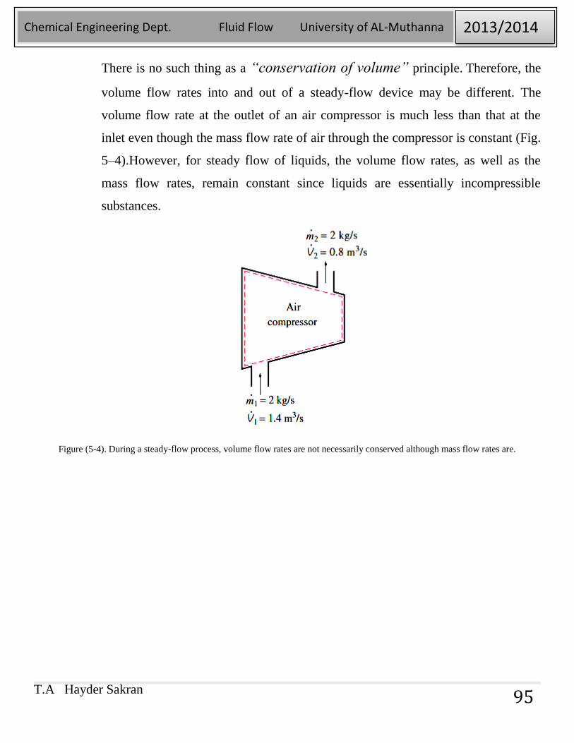
There is no such thing as a “conservation of volume” principle. Therefore, the
volume flow rates into and out of a steady-flow device may be different. The
volume flow rate at the outlet of an air compressor is much less than that at the
inlet even though the mass flow rate of air through the compressor is constant (Fig.
5–4).However, for steady flow of liquids, the volume flow rates, as well as the
mass flow rates, remain constant since liquids are essentially incompressible
substances.
Figure (5-4). During a steady-flow process, volume flow rates are not necessarily conserved although mass flow rates are.
T.A Hayder Sakran
Chemical Engineering Dept. Fluid Flow University of AL-Muthanna 2013/2014
96
T.A Hayder Sakran
Chemical Engineering Dept. Fluid Flow University of AL-Muthanna 2013/2014
97
Problems:
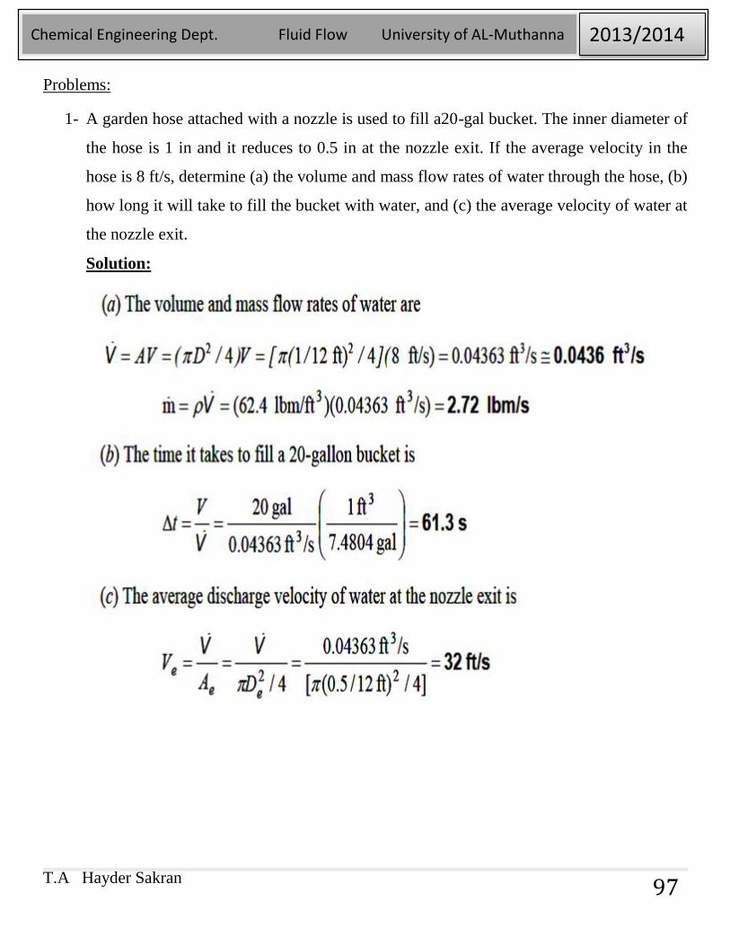
1- A garden hose attached with a nozzle is used to fill a20-gal bucket. The inner diameter of
the hose is 1 in and it reduces to 0.5 in at the nozzle exit. If the average velocity in the
hose is 8 ft/s, determine (a) the volume and mass flow rates of water through the hose, (b)
how long it will take to fill the bucket with water, and (c) the average velocity of water at
the nozzle exit.
Solution:
T.A Hayder Sakran
Chemical Engineering Dept. Fluid Flow University of AL-Muthanna 2013/2014
98
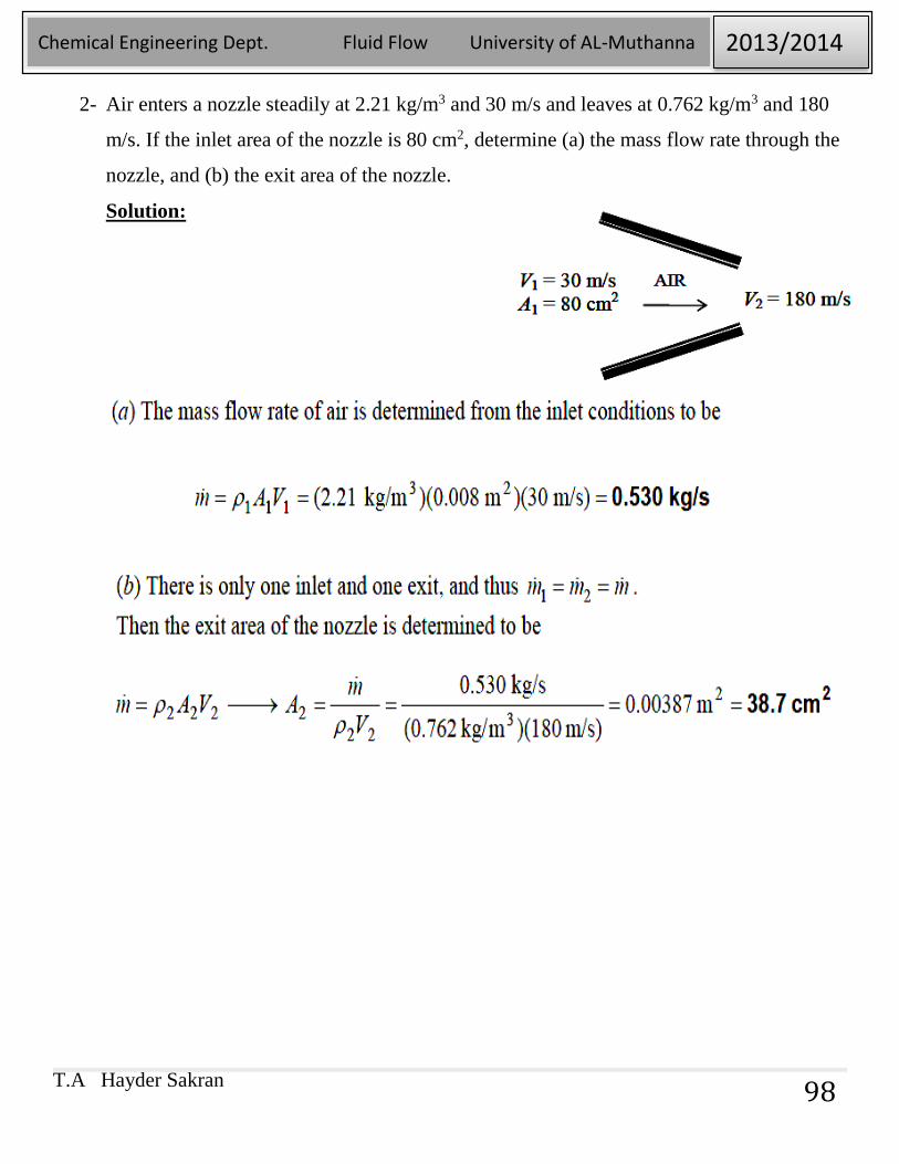
2- Air enters a nozzle steadily at 2.21 kg/m3 and 30 m/s and leaves at 0.762 kg/m3 and 180
m/s. If the inlet area of the nozzle is 80 cm2, determine (a) the mass flow rate through the
nozzle, and (b) the exit area of the nozzle.
Solution:
T.A Hayder Sakran
Chemical Engineering Dept. Fluid Flow University of AL-Muthanna 2013/2014
99
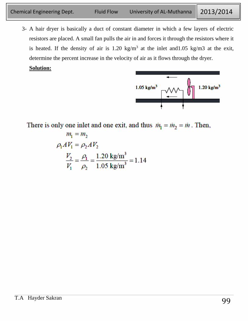
3- A hair dryer is basically a duct of constant diameter in which a few layers of electric
resistors are placed. A small fan pulls the air in and forces it through the resistors where it
is heated. If the density of air is 1.20 kg/m3 at the inlet and1.05 kg/m3 at the exit,
determine the percent increase in the velocity of air as it flows through the dryer.
Solution:
T.A Hayder Sakran
Chemical Engineering Dept. Fluid Flow University of AL-Muthanna 2013/2014
100
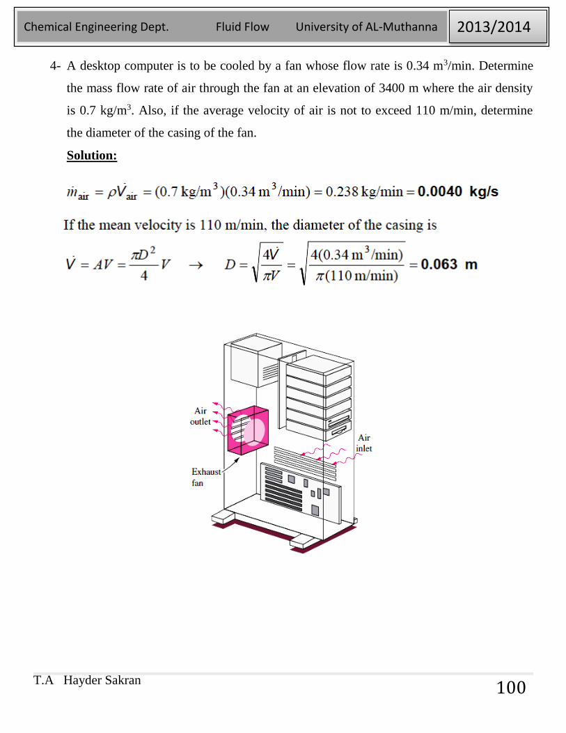
4- A desktop computer is to be cooled by a fan whose flow rate is 0.34 m3/min. Determine
the mass flow rate of air through the fan at an elevation of 3400 m where the air density
is 0.7 kg/m3. Also, if the average velocity of air is not to exceed 110 m/min, determine
the diameter of the casing of the fan.
Solution:
T.A Hayder Sakran
Chemical Engineering Dept. Fluid Flow University of AL-Muthanna 2013/2014
101
5-7. Conservation of Energy:
Energy can be transferred to or from a closed system by heat or work, and the
conservation of energy principle requires that the net energy transfer to or from a
system during a process be equal to the change in the energy content of the system.
Control volumes involve energy transfer via mass flow also, and the conservation
of energy principle, also called the energy balance, is expressed as:
Where �̇�𝑖𝑛 and �̇�𝑜𝑢𝑡 are the total rates of energy transfer into and out of the
control volume, respectively, and dECV/dt is the rate of change of energy within
the control volume boundaries.
5-8. MECHANICAL ENERGY AND EFFICIENCY:
Energy can exist in numerous forms such as thermal, mechanical, kinetic,
potential, electrical, magnetic, chemical, and nuclear, and their sum constitutes the
total energy E (or e on a unit mass) of a system. (J/kg)
The total energy of a fluid in motion consists of the following components: -
1- Internal Energy (U): The forms of energy related to the molecular structure of
a system and the degree of the molecular activity are referred to as the
microscopic energy. The sum of all microscopic forms of energy is called the
internal energy of a system, and is denoted by U (or u on a unit mass).Internal
energy is a function of temperature.
T.A Hayder Sakran
Chemical Engineering Dept. Fluid Flow University of AL-Muthanna 2013/2014
102
2- Potential Energy (PE) : The energy that a system possesses as a result of its
elevation in a gravitational field is called potential energy and is expressed on a
per-unit mass basis as pe = gz where g is the gravitational acceleration and z
is the elevation of the center of gravity of a system relative to some arbitrarily
selected reference plane.
3- Kinetic Energy (KE): The macroscopic energy of a system is related to motion
and the influence of some external effects such as gravity, magnetism,
electricity, and surface tension. The energy that a system possesses as a result of
its motion relative to some reference frame is called kinetic energy. When all
parts of a system move with the same velocity, the kinetic energy per unit mass
is expressed as ke = V2/2 where V denotes the velocity of the system relative
to some fixed reference frame.
4- Flow energy: The pressure force that acting on a fluid through a distance
produces work, called flow work, in the amount of P/ρ per unit mass. Flow
work is expressed in terms of fluid properties, and it is convenient to view it as
part of the energy of a flowing fluid and call it flow energy.
Therefore, the mechanical energy of a flowing fluid can be expressed on a unit-
mass as:
𝑒 = 𝑢 +𝑉2
2+ 𝑔𝑧 +
𝑃
𝜌
Where P/ρ is the flow energy, V2/2 is the kinetic energy, and gz is the potential
energy of the fluid, all per unit mass. Then the mechanical energy change of a
fluid during incompressible flow becomes:
𝛥𝑒𝑚𝑒𝑐ℎ = (𝑢2 − 𝑢1) +𝑉2
2−𝑉21
2+ 𝑔(𝑧2 − 𝑧1) +
𝑃2 − 𝑃1
𝜌
T.A Hayder Sakran
Chemical Engineering Dept. Fluid Flow University of AL-Muthanna 2013/2014
103
Since we consider no change in temperature:
𝑢2 = 𝑢1
𝛥𝑒𝑚𝑒𝑐ℎ =𝑉2
2−𝑉21
2+ 𝑔(𝑧2 − 𝑧1) +
𝑃2 − 𝑃1
𝜌
Therefore, the mechanical energy of a fluid does not change during flow if its
pressure, density, velocity, and elevation remain constant. In the absence of any
losses, the mechanical energy change represents the mechanical work supplied to
the fluid (if Δemech > 0) or extracted from the fluid (if Δemech < 0).
The transfer of mechanical energy is usually accomplished by a rotating shaft, and
thus mechanical work is often referred to as shaft work. A pump or a fan receives
shaft work (usually from an electric motor) and transfers it to the fluid as
mechanical energy (less frictional losses). A turbine, on the other hand, converts
the mechanical energy of a fluid to shaft work.
In fluid systems, we are usually interested in increasing the pressure, velocity,
and/or elevation of a fluid. This is done by supplying mechanical energy to the
fluid by a pump, a fan, or a compressor (we will refer to all of them as pumps). Or
we are interested in the reverse process of extracting mechanical energy from a
fluid by a turbine and producing mechanical power in the form of a rotating shaft
that can drive a generator or any other rotary device. The degree of perfection of
the conversion process between the mechanical work supplied or extracted and the
mechanical energy of the fluid is expressed by the pump efficiency and turbine
T.A Hayder Sakran
Chemical Engineering Dept. Fluid Flow University of AL-Muthanna 2013/2014
104
efficiency, defined as
Where Δ�̇�𝑚𝑒𝑐ℎ,𝑓𝑙𝑢𝑖𝑑 = �̇�𝑚𝑒𝑐ℎ,𝑜𝑢𝑡 − �̇�𝑚𝑒𝑐ℎ,𝑖𝑛 is the rate of increase in
the mechanical energy of the fluid, which is equivalent to the useful pumping
power �̇�𝑝𝑢𝑚𝑝,𝑢 supplied to the fluid, and
where |Δ�̇�𝑚𝑒𝑐ℎ,𝑓𝑙𝑢𝑖𝑑| =�̇�𝑚𝑒𝑐ℎ,𝑖𝑛 − �̇�𝑚𝑒𝑐ℎ,𝑜𝑢𝑡 is the rate of decrease in
the mechanical energy of the fluid, which is equivalent to the mechanical power
extracted from the fluid by the turbine �̇�𝑡𝑢𝑟𝑏𝑖𝑛𝑒,𝑒 , and we use the absolute
value sign to avoid negative values for efficiencies.
The mechanical efficiency should not be confused with the motor efficiency and
the generator efficiency, which are defined as:
T.A Hayder Sakran
Chemical Engineering Dept. Fluid Flow University of AL-Muthanna 2013/2014
105
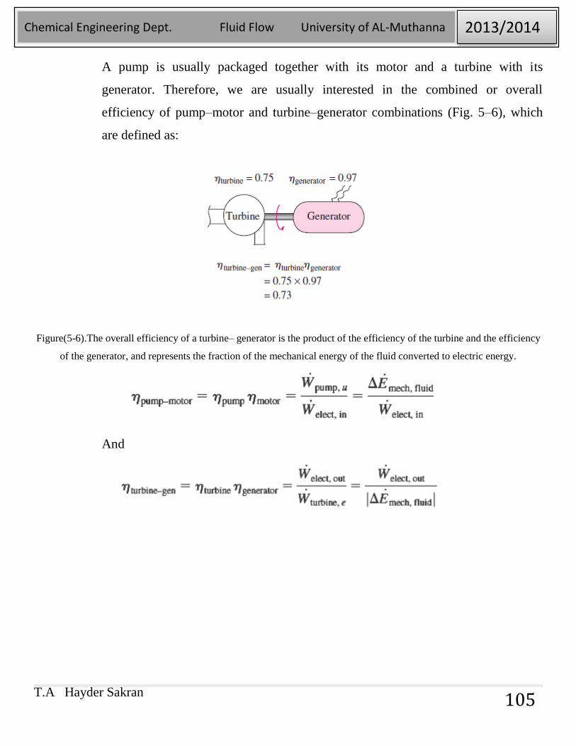
A pump is usually packaged together with its motor and a turbine with its
generator. Therefore, we are usually interested in the combined or overall
efficiency of pump–motor and turbine–generator combinations (Fig. 5–6), which
are defined as:
Figure(5-6).The overall efficiency of a turbine– generator is the product of the efficiency of the turbine and the efficiency
of the generator, and represents the fraction of the mechanical energy of the fluid converted to electric energy.
And
T.A Hayder Sakran
Chemical Engineering Dept. Fluid Flow University of AL-Muthanna 2013/2014
106
T.A Hayder Sakran
Chemical Engineering Dept. Fluid Flow University of AL-Muthanna 2013/2014
107
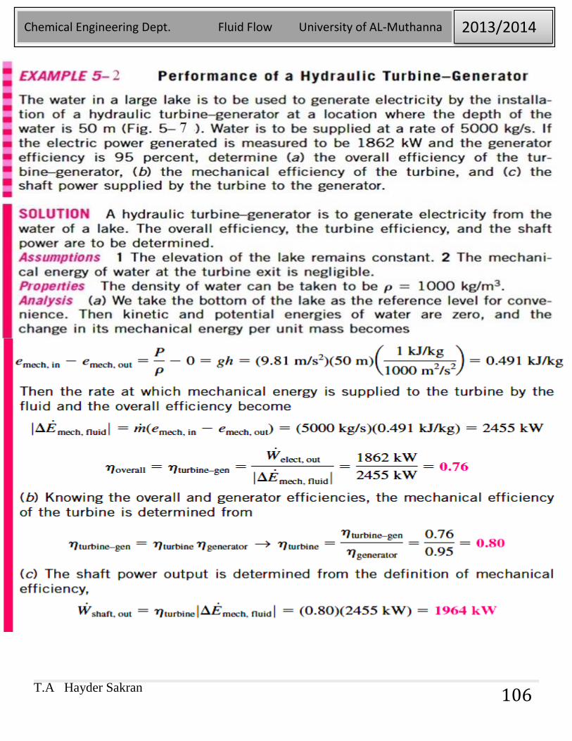
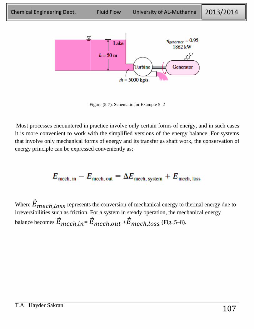
Figure (5-7). Schematic for Example 5–2
Most processes encountered in practice involve only certain forms of energy, and in such cases
it is more convenient to work with the simplified versions of the energy balance. For systems
that involve only mechanical forms of energy and its transfer as shaft work, the conservation of
energy principle can be expressed conveniently as:
Where �̇�𝑚𝑒𝑐ℎ,𝑙𝑜𝑠𝑠 represents the conversion of mechanical energy to thermal energy due to
irreversibilities such as friction. For a system in steady operation, the mechanical energy
balance becomes �̇�𝑚𝑒𝑐ℎ,𝑖𝑛= �̇�𝑚𝑒𝑐ℎ,𝑜𝑢𝑡 +�̇�𝑚𝑒𝑐ℎ,𝑙𝑜𝑠𝑠 (Fig. 5–8).
T.A Hayder Sakran
Chemical Engineering Dept. Fluid Flow University of AL-Muthanna 2013/2014
108
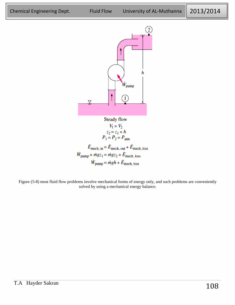
Figure (5-8) most fluid flow problems involve mechanical forms of energy only, and such problems are conveniently
solved by using a mechanical energy balance.
T.A Hayder Sakran
Chemical Engineering Dept. Fluid Flow University of AL-Muthanna 2013/2014
109
5-9. Some cases that we need during our work:
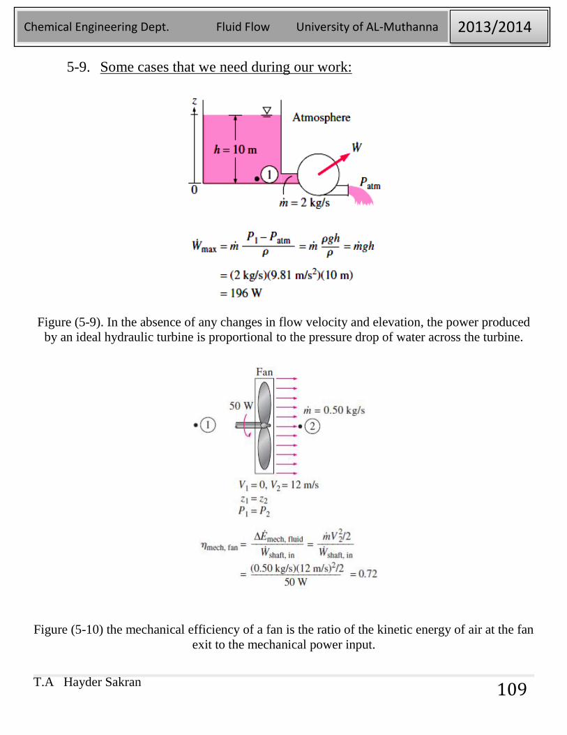
Figure (5-9). In the absence of any changes in flow velocity and elevation, the power produced
by an ideal hydraulic turbine is proportional to the pressure drop of water across the turbine.
Figure (5-10) the mechanical efficiency of a fan is the ratio of the kinetic energy of air at the fan
exit to the mechanical power input.
T.A Hayder Sakran
Chemical Engineering Dept. Fluid Flow University of AL-Muthanna 2013/2014
110
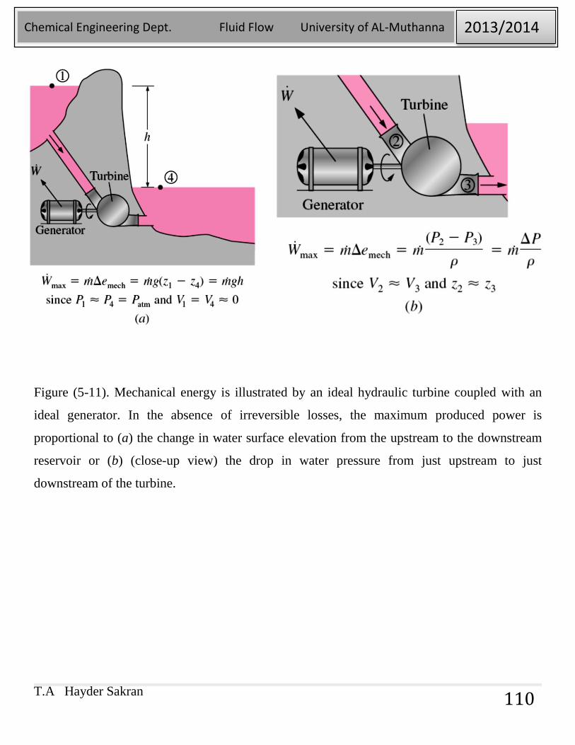
Figure (5-11). Mechanical energy is illustrated by an ideal hydraulic turbine coupled with an
ideal generator. In the absence of irreversible losses, the maximum produced power is
proportional to (a) the change in water surface elevation from the upstream to the downstream
reservoir or (b) (close-up view) the drop in water pressure from just upstream to just
downstream of the turbine.
T.A Hayder Sakran
Chemical Engineering Dept. Fluid Flow University of AL-Muthanna 2013/2014
111
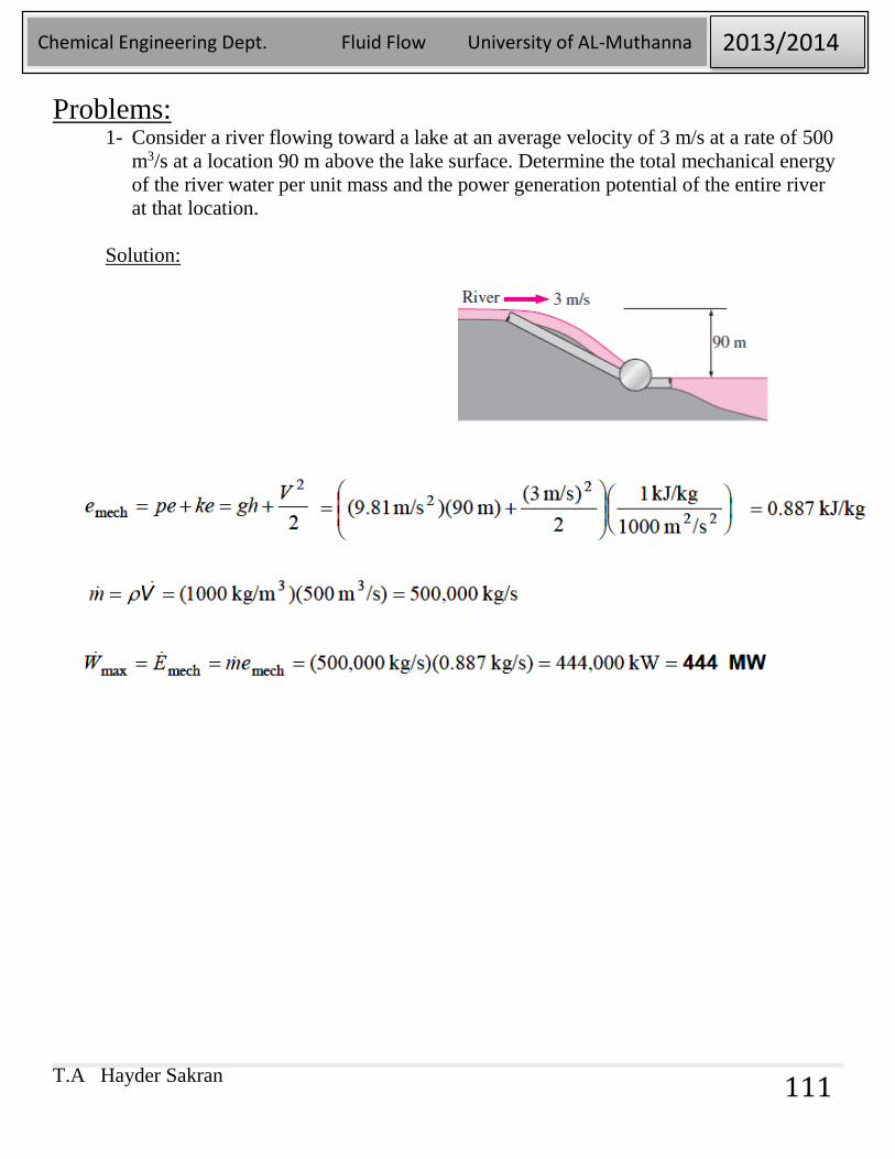
Problems: 1- Consider a river flowing toward a lake at an average velocity of 3 m/s at a rate of 500
m3/s at a location 90 m above the lake surface. Determine the total mechanical energy
of the river water per unit mass and the power generation potential of the entire river
at that location.
Solution:
T.A Hayder Sakran
Chemical Engineering Dept. Fluid Flow University of AL-Muthanna 2013/2014
112
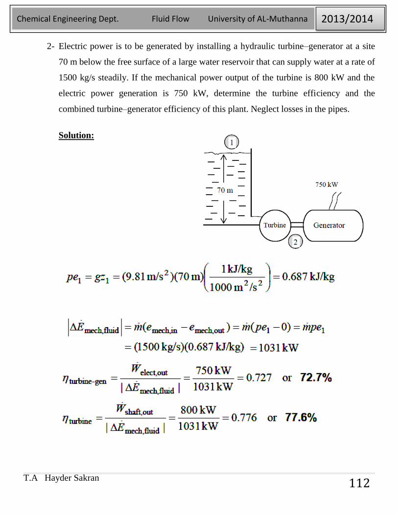
2- Electric power is to be generated by installing a hydraulic turbine–generator at a site
70 m below the free surface of a large water reservoir that can supply water at a rate of
1500 kg/s steadily. If the mechanical power output of the turbine is 800 kW and the
electric power generation is 750 kW, determine the turbine efficiency and the
combined turbine–generator efficiency of this plant. Neglect losses in the pipes.
Solution:
T.A Hayder Sakran
Chemical Engineering Dept. Fluid Flow University of AL-Muthanna 2013/2014
113
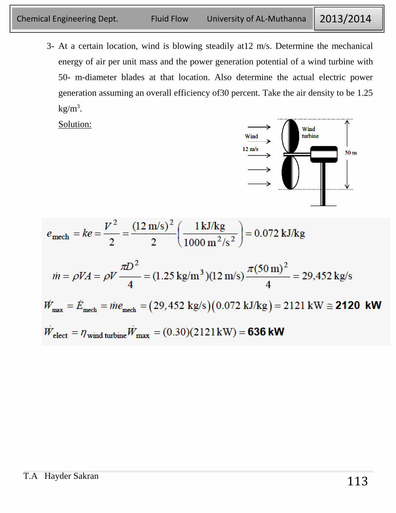
3- At a certain location, wind is blowing steadily at12 m/s. Determine the mechanical
energy of air per unit mass and the power generation potential of a wind turbine with
50- m-diameter blades at that location. Also determine the actual electric power
generation assuming an overall efficiency of30 percent. Take the air density to be 1.25
kg/m3.
Solution: