Embed Size (px)
Citation preview
ENGINEERING GRAPHICS:
Tools for the Mind
A Comprehensive Set of Engineering Graphics Tools
Hand Sketching ♦ Audio/Video Presentation
Lettering Sketching
Orthographic Projection
Isometric Drawings
Oblique Drawings
Auxiliary Views
Sections
Dimensioning
Bryan Graham
University of Alabama
Digital Book
Technical Sketching Orthographic Projection Pictorial Drawings Sections and Conventions Dimensions and Tolerances Dimensioning for Production
Fastening, Joining and Standard Parts Production Drawings Three-Dimensional Geometry Concepts 3-D Geometry Applications Graphical Presentation of Data Design Process
SDC
Schroff Development Corporation
www.schroff.com
PUBLICATIONS
TECHNICAL GRAPHICS
Meyers, Croft, Miller, Demel & Enders Ohio State University
$47.50
Retail Price:
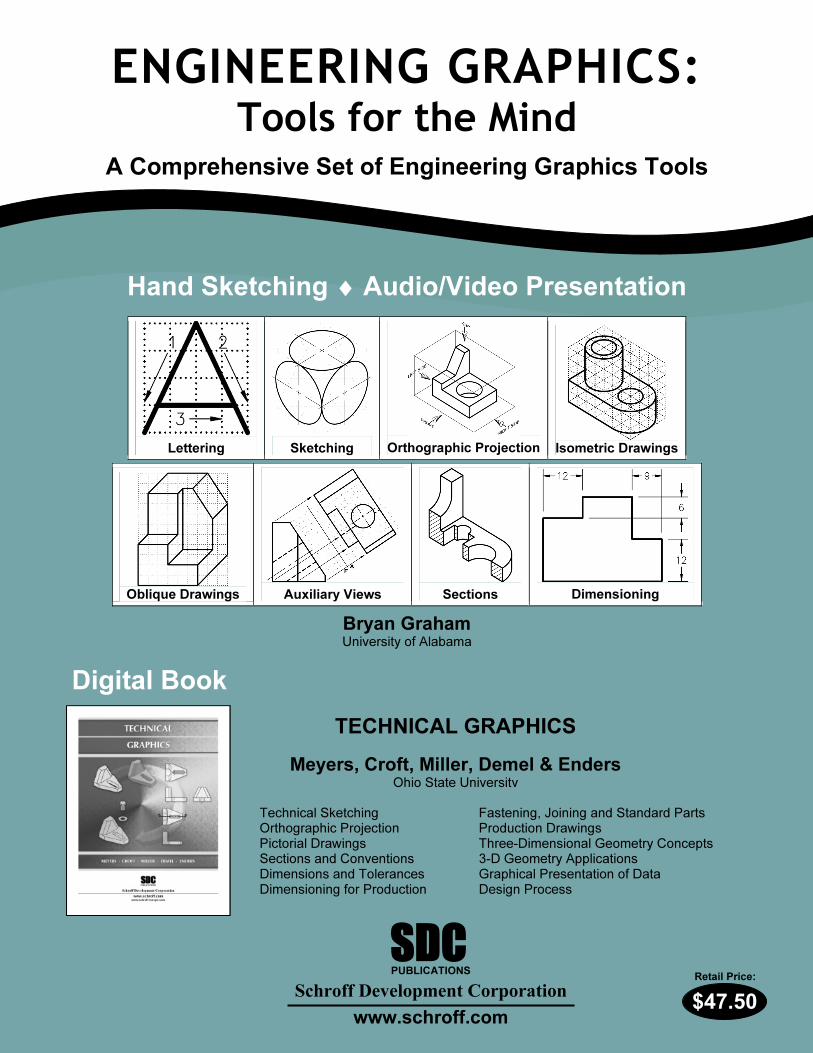
AAuuxxiilliiaarryy VViieewwss For most objects, two or three views drawn orthographically are sufficient to describe the object. However some objects, especially those having an inclined surface, require an additional view to show the inclined surface true size and shape. An auxiliary view is used to provide this true size and shape view. The inclined surface in Figure AUX-1 appears as an edge view in the front view.
In the top and right side views, this inclined surface appears rectangular but does not appear true size and shape. The auxiliary view incorporates the true length measurement of the edge view (found
in the front view) with the true length depth measurement from either the top or right side view and creates a true size and shape view of the inclined surface. A fold line is drawn between views. The distance from the fold line to the front edge of the top view and from the fold line to the front edge of the right side view will be the same measurement. These fold lines are perpendicular to one another and parallel to the edge of the views. Another fold line is drawn between the front view and the auxiliary view. This fold line is drawn parallel to the edge view of the inclined surface in the front view.
FRONT
TOP
RSFRIGHT SIDE
F
T
Figure AUX-1 – The inclined surface appears as an edge in the front view. The surface is foreshortened in the top and right side views.
When drawing orthographically, projections between views are made perpendicular to the fold lines between views. This technique of projecting perpendicular to the fold line is continued when projecting measurements from the front view to the
AUXILIARY VIEWS - 1
Engineering Graphics: Tools for the Mind
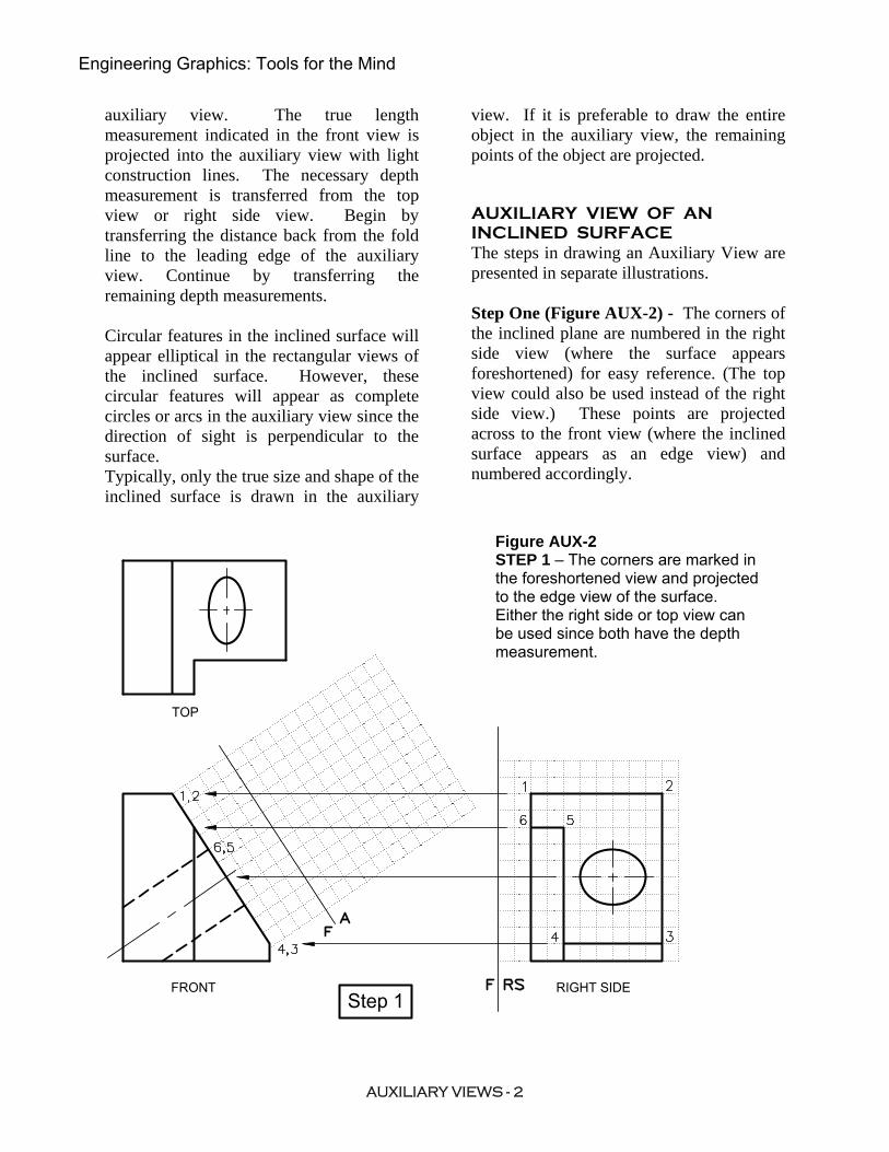
auxiliary view. The true length measurement indicated in the front view is projected into the auxiliary view with light construction lines. The necessary depth measurement is transferred from the top view or right side view. Begin by transferring the distance back from the fold line to the leading edge of the auxiliary view. Continue by transferring the remaining depth measurements. Circular features in the inclined surface will appear elliptical in the rectangular views of the inclined surface. However, these circular features will appear as complete circles or arcs in the auxiliary view since the direction of sight is perpendicular to the surface. Typically, only the true size and shape of the inclined surface is drawn in the auxiliary
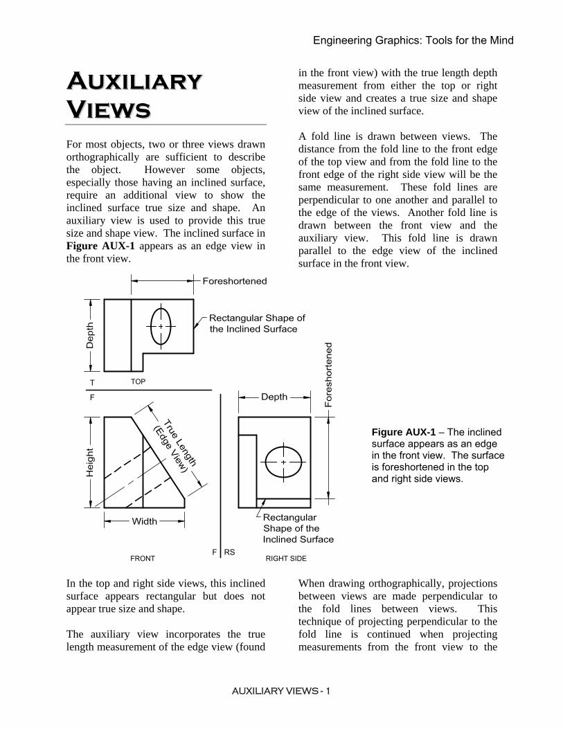
view. If it is preferable to draw the entire object in the auxiliary view, the remaining points of the object are projected. AUXILIARY VIEW OF AN INCLINED SURFACE The steps in drawing an Auxiliary View are presented in separate illustrations. Step One (Figure AUX-2) - The corners of the inclined plane are numbered in the right side view (where the surface appears foreshortened) for easy reference. (The top view could also be used instead of the right side view.) These points are projected across to the front view (where the inclined surface appears as an edge view) and numbered accordingly.
TOP
FRONT RIGHT SIDEStep 1
Figure AUX-2 STEP 1 – The corners are marked in the foreshortened view and projected to the edge view of the surface. Either the right side or top view can be used since both have the depth measurement.
AUXILIARY VIEWS - 2
Engineering Graphics: Tools for the Mind
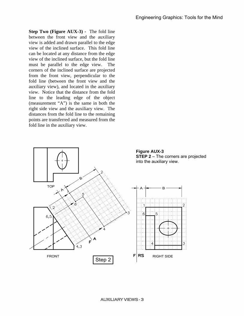
Step Two (Figure AUX-3) - The fold line between the front view and the auxiliary view is added and drawn parallel to the edge view of the inclined surface. This fold line can be located at any distance from the edge view of the inclined surface, but the fold line must be parallel to the edge view. The corners of the inclined surface are projected from the front view, perpendicular to the fold line (between the front view and the auxiliary view), and located in the auxiliary view. Notice that the distance from the fold line to the leading edge of the object (measurement “A”) is the same in both the right side view and the auxiliary view. The distances from the fold line to the remaining points are transferred and measured from the fold line in the auxiliary view.
Figure AUX-3 STEP 2 – The corners are projected into the auxiliary view.
RIGHT SIDEFRONT
TOP
Step 2
AUXILIARY VIEWS - 3
Engineering Graphics: Tools for the Mind
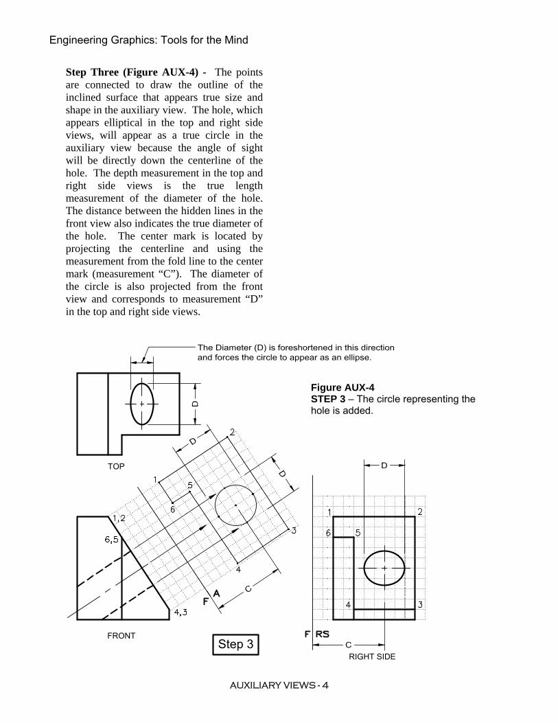
Step Three (Figure AUX-4) - The points are connected to draw the outline of the inclined surface that appears true size and shape in the auxiliary view. The hole, which appears elliptical in the top and right side views, will appear as a true circle in the auxiliary view because the angle of sight will be directly down the centerline of the hole. The depth measurement in the top and right side views is the true length measurement of the diameter of the hole. The distance between the hidden lines in the front view also indicates the true diameter of the hole. The center mark is located by projecting the centerline and using the measurement from the fold line to the center mark (measurement “C”). The diameter of the circle is also projected from the front view and corresponds to measurement “D” in the top and right side views.
Figure AUX-4 STEP 3 – The circle representing the hole is added.
TOP
FRONT
RIGHT SIDEStep 3
AUXILIARY VIEWS - 4
Engineering Graphics: Tools for the Mind
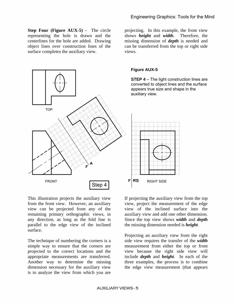
Step Four (Figure AUX-5) - The circle representing the hole is drawn and the centerlines for the hole are added. Drawing object lines over construction lines of the surface completes the auxiliary view.
This illustration projects the auxiliary view from the front view. However, an auxiliary view can be projected from any of the remaining primary orthographic views, in any direction, as long as the fold line is parallel to the edge view of the inclined surface. The technique of numbering the corners is a simple way to ensure that the corners are projected to the correct locations and the appropriate measurements are transferred. Another way to determine the missing dimension necessary for the auxiliary view is to analyze the view from which you are
projecting. In this example, the front view shows height and width. Therefore, the missing dimension of depth is needed and can be transferred from the top or right side views.
Figure AUX-5 STEP 4 – The light construction lines are converted to object lines and the surface appears true size and shape in the auxiliary view.
FRONT
TOP
RIGHT SIDEStep 4
If projecting the auxiliary view from the top view, project the measurement of the edge view of the inclined surface into the auxiliary view and add one other dimension. Since the top view shows width and depth the missing dimension needed is height. Projecting an auxiliary view from the right side view requires the transfer of the width measurement from either the top or front view because the right side view will include depth and height. In each of the three examples, the process is to combine the edge view measurement (that appears
AUXILIARY VIEWS - 5
Engineering Graphics: Tools for the Mind
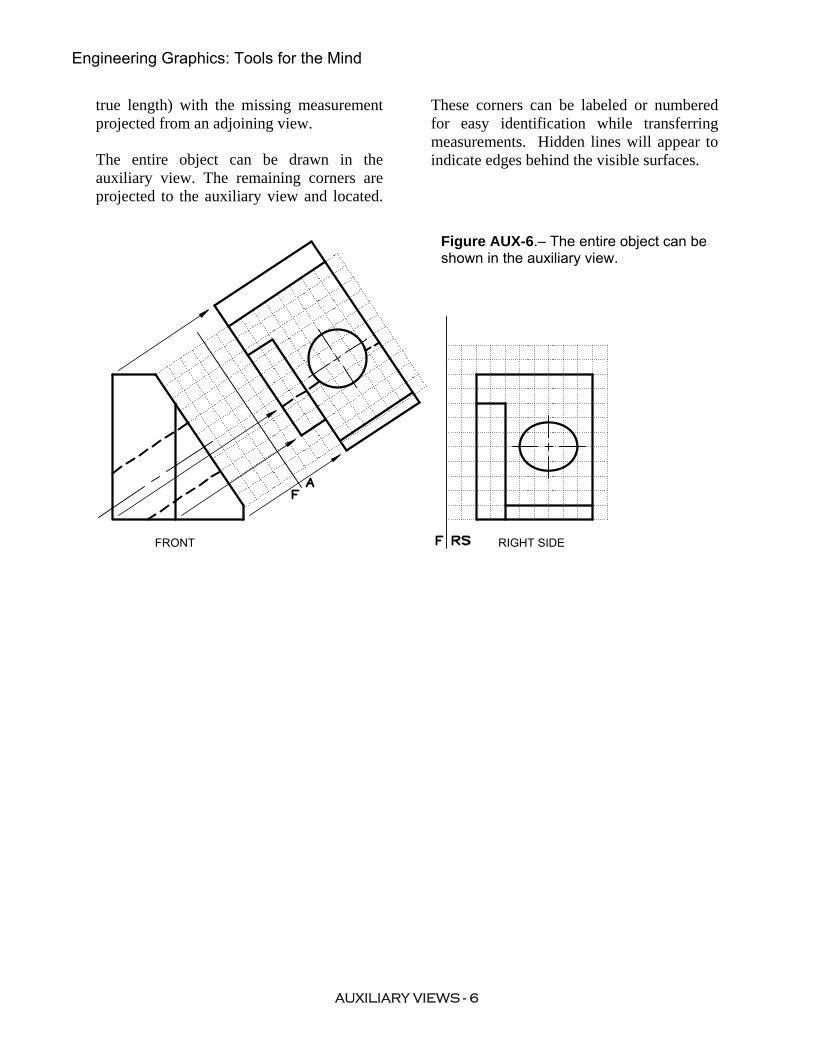
true length) with the missing measurement projected from an adjoining view. The entire object can be drawn in the auxiliary view. The remaining corners are projected to the auxiliary view and located.
These corners can be labeled or numbered for easy identification while transferring measurements. Hidden lines will appear to indicate edges behind the visible surfaces.
Figure AUX-6.– The entire object can be shown in the auxiliary view.
FRONT RIGHT SIDE
AUXILIARY VIEWS - 6
Engineering Graphics: Tools for the Mind
NAME:
FILE NO.: SECTION:
GRADE
ENGINEERING
G R A P H I C S AUX-1
AUXILIARIES
FRONT
4,3
F
A
F RS
4
5
21
6
3
RIGHT SIDE
TOP
F
A
FLS
LEFT SIDE FRONT
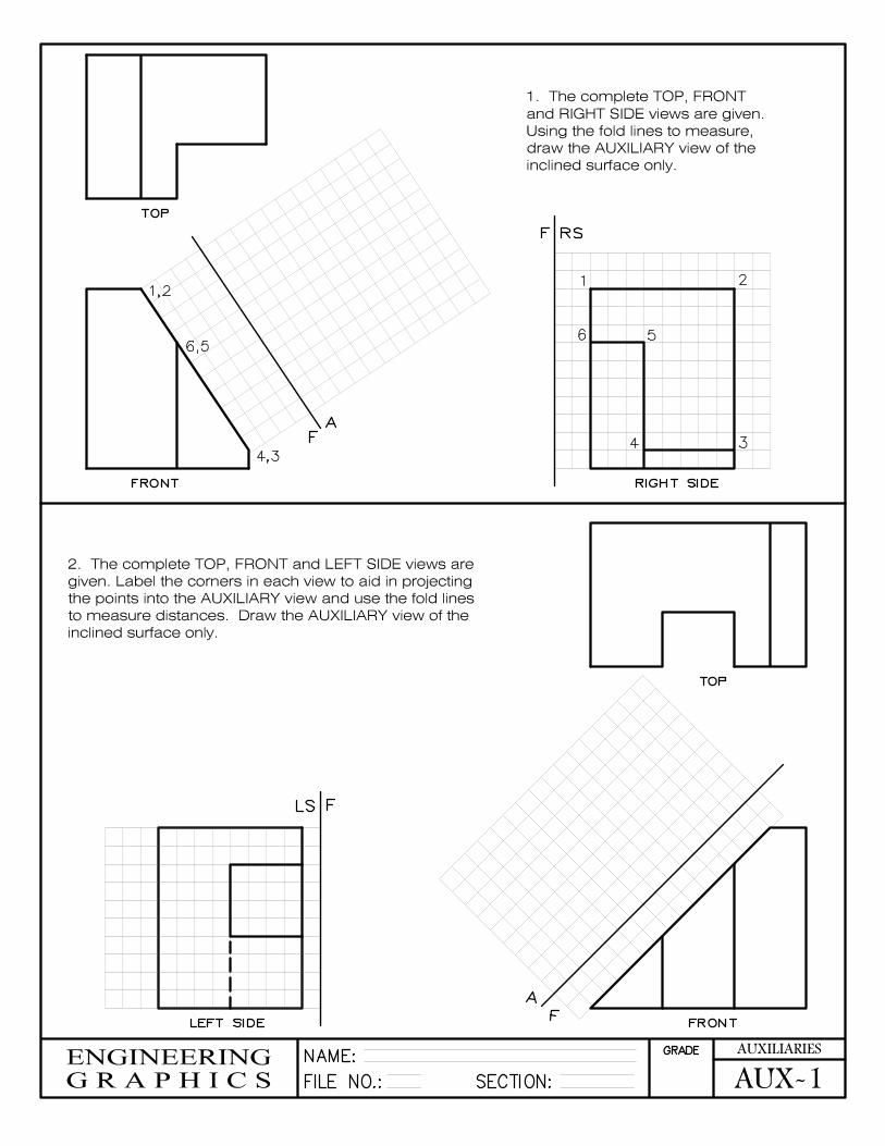
1. The complete TOP, FRONT
and RIGHT SIDE views are given.
Using the fold lines to measure, draw the AUXILIARY view of the
inclined surface only.
2. The complete TOP, FRONT and LEFT SIDE views are
given. Label the corners in each view to aid in projecting
the points into the AUXILIARY view and use the fold lines to measure distances. Draw the AUXILIARY view of the
inclined surface only.
1,2
6,5
TOP
NAME:
FILE NO.: SECTION:
GRADE
ENGINEERING
G R A P H I C S AUX-2
AUXILIARIES
FRONT
4,3
F
A
F RS
4
5
21
6
3
RIGHT SIDE
HORIZONTAL
RS
A
RSF
HORIZONTAL
FRONT RIGHT SIDE
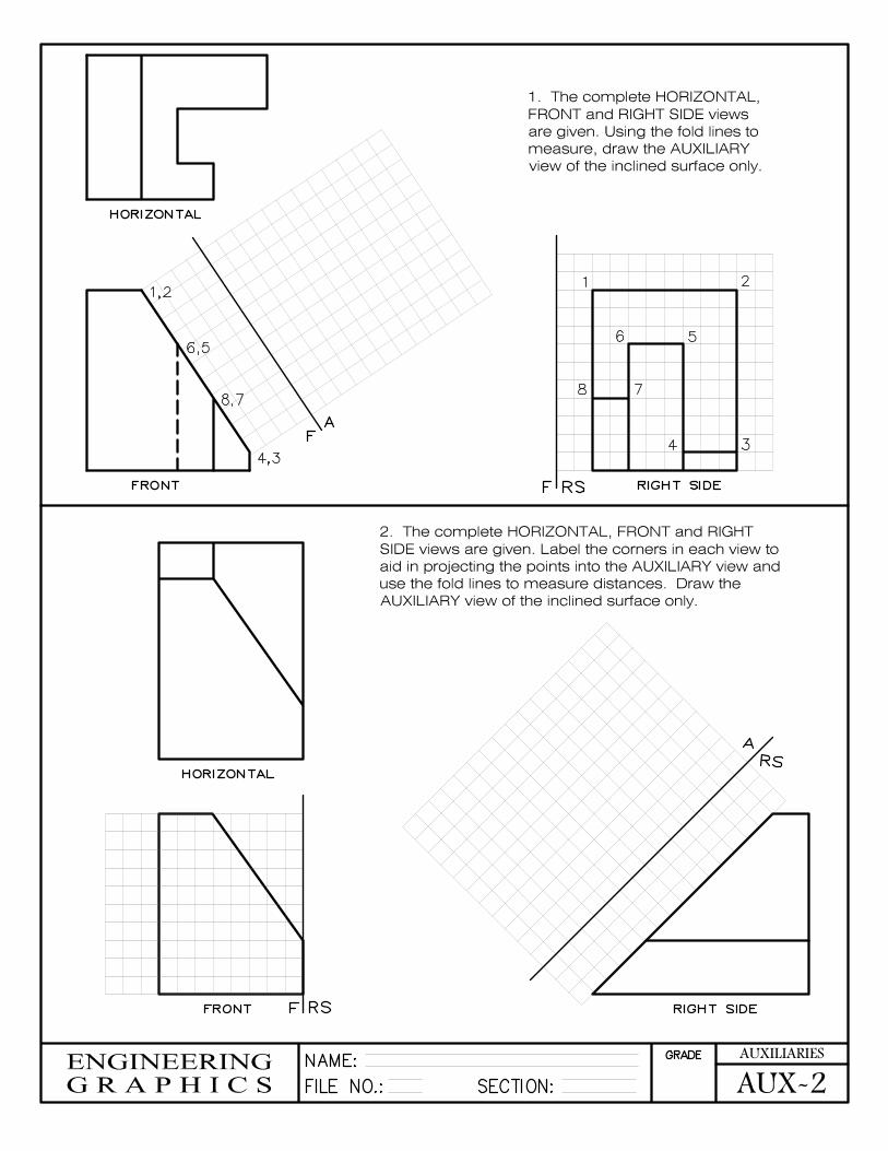
1. The complete HORIZONTAL, FRONT and RIGHT SIDE views
are given. Using the fold lines to
measure, draw the AUXILIARY
view of the inclined surface only.
2. The complete HORIZONTAL, FRONT and RIGHT
SIDE views are given. Label the corners in each view to
aid in projecting the points into the AUXILIARY view and use the fold lines to measure distances. Draw the
AUXILIARY view of the inclined surface only.
78
1,2
6,5
8,7
1,2
5,6
4,3
6
1 2
5
4 3
NAME:
FILE NO.: SECTION:
GRADE
ENGINEERING
G R A P H I C S AUX-3
AUXILIARIES
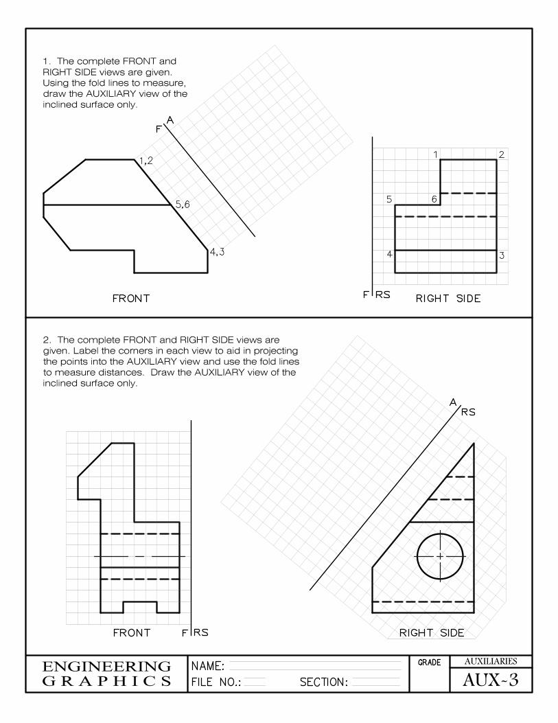
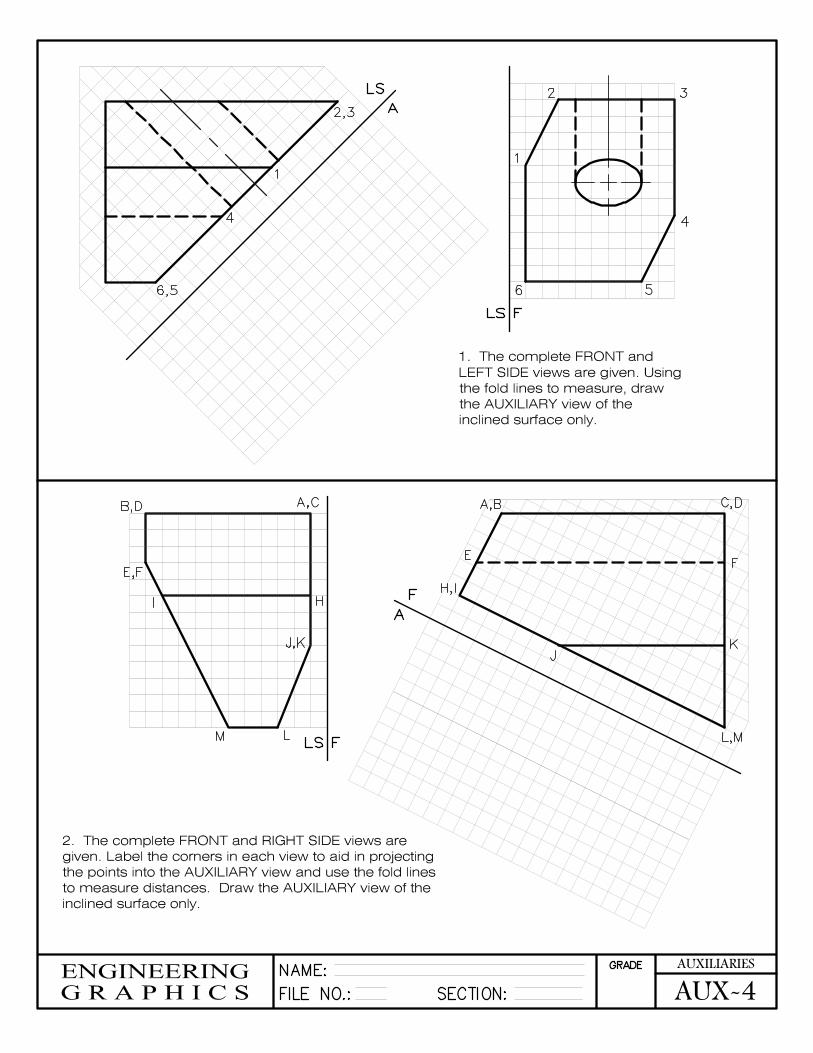
1. The complete FRONT and
RIGHT SIDE views are given.
Using the fold lines to measure, draw the AUXILIARY view of the
inclined surface only.
2. The complete FRONT and RIGHT SIDE views are
given. Label the corners in each view to aid in projecting
the points into the AUXILIARY view and use the fold lines to measure distances. Draw the AUXILIARY view of the
inclined surface only.
FRONT
RIGHT SIDEF RS
F
A
F RS
RS
A
RIGHT SIDE
FRONT
NAME:
FILE NO.: SECTION:
GRADE
ENGINEERING
G R A P H I C S AUX-4
AUXILIARIES
1. The complete FRONT and
LEFT SIDE views are given. Using
the fold lines to measure, draw the AUXILIARY view of the
inclined surface only.
2. The complete FRONT and RIGHT SIDE views are
given. Label the corners in each view to aid in projecting
the points into the AUXILIARY view and use the fold lines to measure distances. Draw the AUXILIARY view of the
inclined surface only.
FLS
LS
A
LS F
F
A
2
1
3
4
56
1
2,3
4
6,5
B,D A,C
E,F
I H
J,K
LM
A,B C,D
EF
H,I
J
K
L,M
NAME:
FILE NO.: SECTION:
GRADE
ENGINEERING
G R A P H I C S AUX-5
AUXILIARIES
F RSRIGHT SIDE
A
FRONT
H
F
F
A
RIGHT SIDERSF
A
F
H
F
A
H
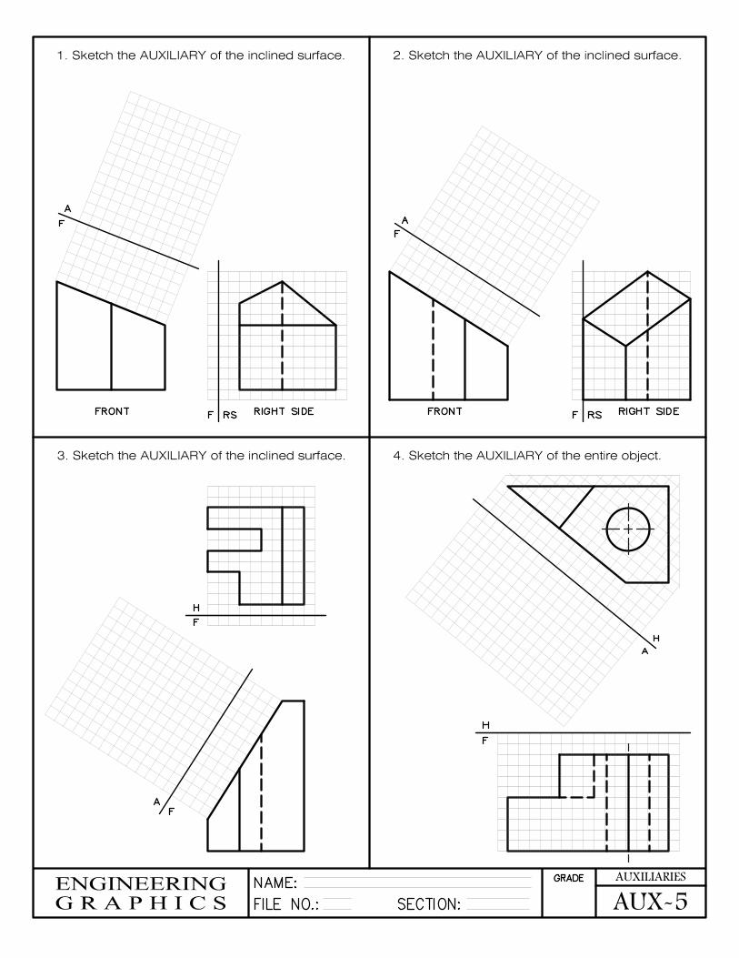
1. Sketch the AUXILIARY of the inclined surface. 2. Sketch the AUXILIARY of the inclined surface.
3. Sketch the AUXILIARY of the inclined surface. 4. Sketch the AUXILIARY of the entire object.
FRONT
F
NAME:
FILE NO.: SECTION:
GRADE
ENGINEERING
G R A P H I C S AUX-6
AUXILIARIES
F LS
LS F
FRONTLEFT SIDE
F
A
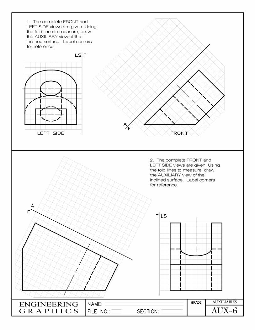
1. The complete FRONT and
LEFT SIDE views are given. Using
the fold lines to measure, draw the AUXILIARY view of the
inclined surface. Label corners
for reference.
F
A
2. The complete FRONT and
LEFT SIDE views are given. Using
the fold lines to measure, draw the AUXILIARY view of the
inclined surface. Label corners
for reference.